JP5629967B2 - Game machine - Google Patents
Game machine Download PDFInfo
- Publication number
- JP5629967B2 JP5629967B2 JP2008180640A JP2008180640A JP5629967B2 JP 5629967 B2 JP5629967 B2 JP 5629967B2 JP 2008180640 A JP2008180640 A JP 2008180640A JP 2008180640 A JP2008180640 A JP 2008180640A JP 5629967 B2 JP5629967 B2 JP 5629967B2
- Authority
- JP
- Japan
- Prior art keywords
- information
- time
- executed
- specific effect
- storage area
- Prior art date
- Legal status (The legal status is an assumption and is not a legal conclusion. Google has not performed a legal analysis and makes no representation as to the accuracy of the status listed.)
- Active
Links
Images


Landscapes
- Pinball Game Machines (AREA)
- Display Devices Of Pinball Game Machines (AREA)
Description
本発明は、遊技機に関するものである。 The present invention relates to a gaming machine.
パチンコ機等の遊技機の多くは、表示装置やスピーカ、ランプ等の演出装置を備えている。近年では、遊技機に電源が投入されてから経過した期間を計測し、経過した期間によって演出装置による特別な演出を行うものも提案されている(例えば特許文献1参照)。
上記従来技術を一歩進めて、遊技機にリアルタイムクロック(以下、RTCという)を備え、日時によって特別な演出を実行することも考えられる(例えば、所定時刻において特定演出を行う)。このようにすれば、予定通りの時刻に特別な演出を実行することができる。 It is conceivable that the above-described conventional technique is advanced one step, and the game machine is provided with a real-time clock (hereinafter referred to as RTC) and a special effect is executed according to the date and time (for example, a specific effect is performed at a predetermined time). In this way, a special effect can be executed at the scheduled time.
しかしながら、RTCを利用して時刻を把握するためには、RTCと制御装置との間で頻繁に信号の送受信を行う必要がある。これにより、時刻情報の入力処理のために要する期間が長くなったり、制御装置にかかる処理負荷が増大したりする等の問題が生じると考えられる。このような問題は、時刻管理を良好に行う阻害事由になると考えられる。 However, in order to grasp the time using the RTC, it is necessary to frequently transmit and receive signals between the RTC and the control device. As a result, problems such as an increase in the time required for the time information input process and an increase in the processing load on the control device may occur. Such a problem is considered to be an obstacle to good time management.
本発明は、上記例示した事情等に鑑みてなされたものであり、時刻管理を良好に行うことができる遊技機を提供することを目的とするものである。 The present invention has been made in view of the above-mentioned circumstances and the like, and an object thereof is to provide a gaming machine capable of performing time management satisfactorily.
以下、上記課題を解決するための手段について記載する。 Hereinafter, means for solving the above problems will be described.
請求項1記載の発明では、
電源が投入された場合に立ち上げ処理を実行する立ち上げ処理手段と、
前記立ち上げ処理の実行後に一定の割込み周期で割込み処理を実行する割込み処理手段と、
演出を実行する演出実行手段と、
演出を実行するよう前記演出実行手段を制御するものであり、当該制御のための所定処理を前記割込み処理手段による一定の割込み周期毎に実行する制御手段と、
前記割込み処理手段による一定の割込み周期毎に期間経過情報を更新する経過情報更新手段と、
識別情報が記憶される識別記憶手段と、
前記立ち上げ処理の場合にのみ暦情報を入力する暦情報入力手段と、
を備え、
前記制御手段は、前記更新された期間経過情報、前記入力された暦情報及び前記識別情報に基づいて予め定めた演出を実行するよう前記演出実行手段を制御することを特徴とする。
In invention of
A startup processing means for executing startup processing when the power is turned on;
Interrupt processing means for executing interrupt processing at a constant interrupt cycle after execution of the startup processing;
Production execution means for performing production,
Control means for controlling the effect execution means so as to execute an effect, and executing a predetermined process for the control at a certain interrupt cycle by the interrupt processing means ;
Progress information updating means for updating period elapsed information for each predetermined interrupt cycle by the interrupt processing means;
Identification storage means for storing identification information;
Calendar information input means for inputting calendar information only in the case of the startup process;
With
The control means controls the effect executing means to execute a predetermined effect based on the updated period elapsed information, the input calendar information, and the identification information.
本発明によれば、時刻管理を良好に行うことができる。 According to the present invention, time management can be performed satisfactorily.
<第1の実施形態>
以下、遊技機の一種であるパチンコ遊技機(以下、「パチンコ機」という)の一実施の形態を、図面に基づいて詳細に説明する。図1はパチンコ機10の正面図、図2はパチンコ機10の主要な構成を展開して示す斜視図、図3はパチンコ機10の背面図である。なお、図2では便宜上パチンコ機10の遊技領域内の構成を省略している。
<First Embodiment>
Hereinafter, an embodiment of a pachinko gaming machine (hereinafter referred to as “pachinko machine”), which is a type of gaming machine, will be described in detail with reference to the drawings. FIG. 1 is a front view of the
パチンコ機10は、当該パチンコ機10の外殻を形成する外枠11と、この外枠11に対して前方に回動可能に取り付けられた遊技機主部12とを有する。外枠11は木製又は合成樹脂製の板材を四辺に連結し構成されるものであって矩形枠状をなしている。パチンコ機10は、外枠11を島設備に取り付け固定することにより遊技ホールに設置される。
The
遊技機主部12は、ベース体としての本体枠13と、その本体枠13の前方に配置される前扉枠14と、本体枠13の後方に配置される裏パックユニット15とを備えている。遊技機主部12のうち本体枠13が外枠11に対して回動可能に支持されている。詳細には、正面視で左側を回動基端側とし右側を回動先端側として本体枠13が前方へ回動可能とされている。
The gaming machine
本体枠13には、前扉枠14と裏パックユニット15とがそれぞれ回動可能に支持されている。前扉枠14は、正面視で左側を回動基端側、右側を回動先端側として本体枠13に対して前方へ回動可能とされている。また、裏パックユニット15は、正面視で左側を回動基端側、右側を回動先端側として本体枠13に対して後方へ回動可能とされている。
A
前扉枠14は、本体枠13の前面側全体を覆うようにして設けられている。前扉枠14には、後述する遊技領域のほぼ全域を前方から視認することができるようにした窓部21が形成されている。窓部21は略楕円形状をなし、透明性を有するガラス22が嵌め込まれている。窓部21の周囲には、各種ランプ等の発光手段が設けられている。例えば、窓部21の周縁に沿ってLED等の発光手段を内蔵した環状電飾部23が設けられている。環状電飾部23では、大当たり時や所定のリーチ時等における遊技状態の変化に応じて点灯や点滅が行われる。また、環状電飾部23の中央であってパチンコ機10の最上部には所定のエラー時に点灯するエラー表示ランプ部24が設けられ、さらにその左右側方には賞球払出中に点灯する賞球ランプ部25が設けられている。また、左右の賞球ランプ部25に近接した位置には、遊技状態に応じた効果音などが出力されるスピーカ部26が設けられている。
The
前扉枠14における窓部21の下方には、手前側へ膨出することで上下2段に膨出部31,32(上側膨出部31、下側膨出部32)が設けられている。上側膨出部31には上方に開口した上皿33が設けられ、下側膨出部32には同じく上方に開口した下皿34が設けられている。上皿33は、後述する払出装置より払い出された遊技球を一旦貯留し、一列に整列させながら後述する遊技球発射装置側へ導くための機能を有する。また、下皿34は、上皿33内にて余剰となった遊技球を貯留する機能を有する。下側膨出部32の右方には、手前側へ突出するようにして遊技球発射ハンドル36が設けられている。遊技球発射ハンドル36が操作されることにより、後述する遊技球発射装置から遊技球が発射される。
Below the
前扉枠14の背面には、後述する払出装置により払い出される遊技球を上皿33と下皿34とに振り分けて流通させる通路形成ユニット37が取り付けられている。その他、前扉枠14の背面にはその回動先端側に、本体枠13に対する施錠機構を構成する鉤金具38が上下方向に複数設けられている。
A
本体枠13は、外形が外枠11とほぼ同一形状をなす樹脂ベース41を主体として構成されており、その回動先端側には、前扉枠14に設けられた鉤金具38を挿入するための挿入孔42が複数設けられている。鉤金具38が挿入孔42に挿入されることで、図示しない施錠装置が係止状態となり、前扉枠14が本体枠13に対して開放不能に施錠される。樹脂ベース41の右下隅部には、施錠装置の解錠操作を行うためのシリンダ錠43が設置されており、シリンダ錠43の鍵穴に差し込んだキーを右に回すと本体枠13に対する前扉枠14の施錠が解かれるようになっている。なお、シリンダ錠43の鍵穴に差し込んだキーを左に回すと外枠11に対する本体枠13の施錠が解かれるようになっている。
The
樹脂ベース41の中央部には略楕円形状の窓孔44が形成されている。樹脂ベース41には、窓孔44の下方に遊技球発射装置45が取り付けられている。遊技球発射装置45は、例えばソレノイド駆動式の発射機構を有しており、ソレノイドへの電気信号の入力により出力軸が伸縮方向に移動し、発射レール上の遊技球が遊技領域に向けて順次打ち出される。
A substantially
また、樹脂ベース41には遊技盤51が着脱可能に取り付けられている。遊技盤51は合板よりなり、遊技盤51の前面に形成された遊技領域が樹脂ベース41の窓孔44を通じて本体枠13の前面側に露出した状態となっている。
A
ここで、パチンコ機10の前方側における遊技盤51の構成を図4に基づいて説明する。遊技盤51には、ルータ加工が施されることによって前後方向に貫通する大小複数の開口部が形成されている。各開口部には一般入賞口52,可変入賞装置53,作動口54,スルーゲート55及び可変表示ユニット56等がそれぞれ設けられている。一般入賞口52、可変入賞装置53及び作動口54に遊技球が入ると、それが図示しない検知スイッチにより検知され、その検知結果に基づいて所定数の賞球の払い出しが実行される。その他に、遊技盤51の最下部にはアウト口57が設けられており、各種入賞口等に入らなかった遊技球はアウト口57を通って遊技領域から排出される。また、遊技盤51には、遊技球の落下方向を適宜分散、調整等するために多数の釘58が植設されているとともに、風車等の各種部材(役物)が配設されている。
Here, the configuration of the
可変表示ユニット56には、作動口54への入賞をトリガとして図柄を可変表示する図柄表示部61が設けられている。また、可変表示ユニット56には、図柄表示部61を囲むようにしてセンターフレーム62が配設されている。センターフレーム62の上部には、第1特定ランプ部63及び第2特定ランプ部64が設けられている。また、センターフレーム62の上部及び下部にはそれぞれ保留ランプ部65,66が設けられている。下側の保留ランプ部65は、図柄表示部61及び第1特定ランプ部63に対応しており、遊技球が作動口54を通過した回数は最大4回まで保留され保留ランプ部65の点灯によってその保留個数が表示されるようになっている。上側の保留ランプ部66は、第2特定ランプ部64に対応しており、遊技球がスルーゲート55を通過した回数は最大4回まで保留され保留ランプ部66の点灯によってその保留個数が表示されるようになっている。
The
第1特定ランプ部63では、作動口54への入賞をトリガとして所定の順序で発光色の切り替えが行われ、予め定められた色で停止表示された場合には大当たりが発生する。また、第2特定ランプ部64では、遊技球のスルーゲート55の通過をトリガとして所定の順序で発光色の切り替えが行われ、予め定められた色で停止表示された場合には作動口54に付随する電動役物が所定時間だけ開放状態となる。
In the first
可変入賞装置53は、通常は遊技球が入賞できない又は入賞し難い閉状態になっており、大当たりの際に遊技球が入賞しやすい所定の開放状態に切替えられるようになっている。可変入賞装置53の開放態様としては、所定時間(例えば30秒間)の経過又は所定個数(例えば10個)の入賞を1ラウンドとして、複数ラウンド(例えば15ラウンド)を上限として繰り返し開放されるものが一般的である。
The
遊技盤51には、内レール部67と外レール部68とが取り付けられており、これら各レール部67,68により誘導レールが構成され、遊技球発射装置45から発射された遊技球が遊技領域の上部に案内されるようになっている。
An
次に、遊技盤51の背面における構成を図5を用いて説明する。
Next, the configuration on the back surface of the
遊技盤51に取り付けられる可変表示ユニット56の背後には、音声ランプ制御装置70がその背後に設けられているとともに表示制御装置が搭載された制御ユニット71が取り付けられている。音声ランプ制御装置70は、後述する主制御装置からの指示に従い音声やランプ表示、及び表示制御装置の制御を司る音声ランプ制御基板を具備しており、音声ランプ制御基板が透明樹脂材料等よりなる基板ボックスに収容されて構成されている。
Behind the
また、遊技盤51の背面において、可変表示ユニット56や音声ランプ制御装置70の下方には主制御装置72が搭載されている。主制御装置72は、遊技の主たる制御を司る機能(主制御回路)と、電源を監視する機能(停電監視回路)とを有する主制御基板を具備しており、当該主制御基板が透明樹脂材料等よりなる基板ボックスに収容されて構成されている。制御ユニット71の側方に位置するようにしてID情報設定装置75が設けられており、ID情報設定装置75の上方に位置するようにして演出スイッチ76が設けられている。
A
次に、パチンコ機10の背面構成を図3を用いて説明する。
Next, the back configuration of the
図3において、裏パックユニット15は、透明性を有する合成樹脂により成形されてなる裏パック81を備えている。裏パック81は、樹脂ベース41とほぼ同じ外寸法を有しかつ略中央部に矩形状の開口部82aを有するベース部82と、パチンコ機10後方に突出するようにしてベース部82の開口部82aに設けられる保護カバー部83とを有する。保護カバー部83は左右側面及び上面が閉鎖されかつ下面のみが開放された略直方体形状をなし、少なくとも可変表示ユニット56を囲むのに十分な大きさを有する。
In FIG. 3, the
ベース部82には、その右上部に外部端子板84が設けられている。外部端子板84には各種の出力端子が設けられており、これらの出力端子を通じて遊技ホール側の管理制御装置に対して各種信号が出力される。
The
ベース部82には、保護カバー部83を迂回するようにして払出機構部が配設されている。すなわち、裏パック81の最上部には上方に開口したタンク86が設けられており、タンク86には遊技ホールの島設備から供給される遊技球が逐次補給される。タンク86の下方には、下流側に向けて緩やかに傾斜するタンクレール87が連結され、タンクレール87の下流側には上下方向に延びるケースレール88が連結されている。ケースレール88の最下流部には払出装置89が設けられている。払出装置89より払い出された遊技球は、払出装置89の下流側に設けられた払出通路や遊技球分配部を経由して上皿33や下皿34に供給される。
The
ベース部82において開口部82aの下方には、払出制御装置91と電源・発射制御装置92とが搭載されている。これら各制御装置91,92は、払出制御装置91がパチンコ機10後方となるように前後に重ねて配置されている。払出制御装置91は、払出装置を制御する払出制御基板が基板ボックス内に収容されて構成されている。電源・発射制御装置92は、電源・発射制御基板が基板ボックス内に収容されて構成されており、当該基板により、各種制御装置等で要する所定の電源が生成されて出力され、さらに遊技者による遊技球発射ハンドル36の操作に伴う遊技球の打ち出しの制御が行われる。
In the
次に、パチンコ機10の電気的構成について、図6のブロック図に基づいて説明する。なお、図6では、信号ラインを実線矢印で示す。
Next, the electrical configuration of the
主制御装置72は、停電監視回路100とCPU101とを備えている。CPU101には、当該CPU101により実行される各種の制御プログラムや固定値データを記憶したROMと、そのROM内に記憶される制御プログラムの実行に際して各種のデータ等を一時的に記憶するためのメモリであるRAMと、割込回路やタイマ回路、データ入出力回路などの各種回路とが内蔵されている。
The
一方、主制御装置72におけるCPU101の出力側には、払出制御装置91のCPU102と音声ランプ制御装置70のCPU103とが接続されている。詳細には、主制御装置72におけるCPU101と、音声ランプ制御装置70におけるCPU103とは、入出力ポート105を介して接続されている。CPU101は、払出制御装置91のCPU102に対して賞球コマンド等の各種コマンドを出力する一方、音声ランプ制御装置70のCPU103に対して演出コマンド等の各種コマンドを出力する。また、主制御装置72のCPU101には停電監視回路100を介して電源・発射制御装置92から電力が供給される。停電監視回路190は、CPU101に対して正常な電力量が供給されているか否かを監視している。
On the other hand, the
払出制御装置91は、払出装置89による賞球や貸し球の払出制御を行うものである。払出制御装置91におけるCPU102は、そのCPU102により実行される制御プログラムや固定値データ等を記憶したROMと、ワークメモリ等として使用されるRAMとを備えている。
The
電源・発射制御装置92は発射制御部を備えており、発射制御部は遊技者による遊技球発射ハンドル36の操作に従って遊技球発射装置45の発射制御を担うものであり、遊技球発射装置45は所定の発射条件が整っている場合に駆動される。
The power supply /
音声ランプ制御装置70におけるCPU103は、各種ランプ部23〜25やスピーカ部26、及び表示制御装置110を制御するものである。音声ランプ制御装置70におけるCPU103は、そのCPU103により実行される制御プログラムや固定値データ等を記憶したROM113と、ワークメモリ等として使用されるRAM115とを備えている。また、音声ランプ制御装置70には、年月日情報及び時刻情報を出力するRTC120(リアルタイムクロック)が設けられている。なお、RTC120は、バックアップ電源を備えている。これにより、パチンコ機10の電源遮断時においても時刻経過を管理できるようになっている。
The
RAM115は、RTC120から入力した年月日情報及び時刻情報を記憶する記憶手段としてのタイマカウンタ115aを備えている。音声ランプ制御装置70は、年月日情報を入力した場合、電源投入時にのみにタイマカウンタ115aに設けられた年月日情報を記憶する領域を書き替えるようになっている。また、音声ランプ制御装置70は、時刻情報を入力した場合、タイマカウンタ115aに設けられた時刻情報に対応した領域を書き替えるようになっている。時刻情報に対応した領域が一定周期毎に書き替えられることによって、現在の時刻をパチンコ機10にて把握可能となっている。音声ランプ制御装置70におけるCPU103とRTC120とはそれぞれ入出力ポート105を介して接続されている。
The
音声ランプ制御装置70におけるCPU103の入力側には主制御装置72におけるCPU101が入出力ポート105を介して接続されている。そして、CPU103は、主制御装置72側から入力した各種コマンドに基づいて各種ランプ部23〜25やスピーカ部26、及び表示制御装置110を制御する。
The
入出力ポート105には、ID情報を出力するID情報設定装置75と、特定演出を実行するか否かの決定に用いる演出スイッチ76と、が接続されている。ID情報設定装置75が出力するID情報は、パチンコ機10が設置される遊技ホール等における管理者にID情報設定装置75に設けられたスイッチが操作されることにより設定される。
The input /
表示制御装置110は、音声ランプ制御装置70から受信したコマンドに基づいて図柄表示装置130を表示制御する。図柄表示装置130に画像等が表示されることにより、図柄表示部61にて画像等が視認されることとなる。
The
次に、上記の如く構成されたパチンコ機10の動作について説明する。
Next, the operation of the
本実施の形態では、主制御装置72内のCPU101は、遊技に際し各種カウンタ情報を用いて、大当たり抽選等を行うこととしており、具体的には、図7に示すように、大当たりの抽選に使用する大当たり乱数カウンタC1と、大当たり種別の選択に使用する大当たり種別カウンタC2と、図柄表示装置130にて図柄の変動表示が外れ変動する際のリーチ抽選に使用するリーチ乱数カウンタC3と、大当たり乱数カウンタC1の初期値設定に使用する乱数初期値カウンタCINIと、図柄表示装置130の変動パターン選択に使用する変動種別カウンタCSとを用いることとしている。
In the present embodiment, the
このうち、カウンタC1〜C3,CINI,CSは、その更新の都度前回値に1が加算され、最大値に達した後0に戻るループカウンタとなっている。主制御装置72におけるRAMには、1つの実行エリアと4つの保留エリア(保留第1〜第4エリア)とからなる保留球格納エリアが設けられており、これらの各エリアには、作動口54への遊技球の入賞履歴に合わせて、大当たり乱数カウンタC1、大当たり図柄カウンタC2及びリーチ乱数カウンタC3の各値が時系列的に格納されるようになっている。
Among these counters, the counters C1 to C3, CINI, and CS are loop counters that add 1 to the previous value every time they are updated, and return to 0 after reaching the maximum value. The RAM in the
各カウンタについて詳しくは、大当たり乱数カウンタC1は、例えば0〜676の範囲内で順に1ずつ加算され、最大値(つまり676)に達した後0に戻る構成となっている。特に大当たり乱数カウンタC1が1周した場合、その時点の乱数初期値カウンタCINIの値が当該大当たり乱数カウンタC1の初期値として読み込まれる。なお、乱数初期値カウンタCINIは、大当たり乱数カウンタC1と同様のループカウンタであり(値=0〜676)、タイマ割込み毎に1回更新されるとともに通常処理の残余時間内で繰り返し更新される。大当たり乱数カウンタC1は定期的に(本実施の形態ではタイマ割込み毎に1回)更新され、遊技球が作動口54に入賞したタイミングでRAMの保留球格納エリアに格納される。大当たりとなる乱数の値の数は、通常状態と高確率状態とで2種類設定されており、通常時に大当たりとなる乱数の値の数は2で、その値は「337,673」であり、高確率時に大当たりとなる乱数の値の数は10で、その値は「67,131,199,269,337,401,463,523,601,661」である。
For details of each counter, the jackpot random number counter C1 is configured such that, for example, 1 is sequentially added within a range of 0 to 676, and after reaching the maximum value (that is, 676), it returns to 0. In particular, when the jackpot random number counter C1 makes one round, the value of the random number initial value counter CINI at that time is read as the initial value of the jackpot random number counter C1. The random number initial value counter CINI is a loop counter similar to the jackpot random number counter C1 (value = 0 to 676), and is updated once for each timer interrupt and is repeatedly updated within the remaining time of the normal processing. The jackpot random number counter C1 is updated periodically (once every timer interruption in the present embodiment), and stored in the reserved ball storage area of the RAM at the timing when the game ball wins the
大当たり図柄カウンタC2は、大当たりが終了した場合に高確率状態に移行する特定大当たりであるか、大当たりが終了した場合に通常状態に移行する非特定大当たりであるかを決定するものである。本実施の形態では、0〜49のカウンタ値が用意されており、すなわち、大当たり図柄カウンタC2は、0〜49の範囲内で順に1ずつ加算され、最大値(つまり49)に達した後0に戻る構成となっている。大当たり図柄カウンタC2は定期的に(本実施の形態ではタイマ割込み毎に1回)更新され、遊技球が作動口54に入賞したタイミングでRAMの保留球格納エリアに格納される。
The jackpot symbol counter C2 determines whether the jackpot is a specific jackpot that shifts to a high probability state when the jackpot ends or a non-special jackpot that shifts to a normal state when the jackpot ends. In the present embodiment, counter values from 0 to 49 are prepared, that is, the jackpot symbol counter C2 is incremented by 1 within the range from 0 to 49, and reaches 0 after reaching the maximum value (ie, 49). It is the composition which returns to. The jackpot symbol counter C2 is updated periodically (once every timer interruption in the present embodiment), and stored in the reserved ball storage area of the RAM at the timing when the game ball wins the
リーチ乱数カウンタC3は、例えば0〜299の範囲内で順に1ずつ加算され、最大値(つまり299)に達した後0に戻る構成となっている。本実施の形態では、リーチ乱数カウンタC3によって、リーチが発生した後最終停止図柄がリーチ図柄の前後に1つだけずれて停止する「前後外れリーチ」と、同じくリーチ発生した後最終停止図柄がリーチ図柄の前後以外で停止する「前後外れ以外リーチ」と、リーチ発生しない「完全外れ」とを抽選することとしており、例えば、C3=0が前後外れリーチに該当し、C3=1〜25が前後外れ以外リーチに該当し、C3=26〜299が完全外れに該当する。なお、リーチの抽選は、図柄表示装置130の抽選確率の状態や変動開始時の作動保留球数等に応じて各々個別に設定されるものであっても良い。リーチ乱数カウンタC3は定期的に(本実施の形態ではタイマ割込み毎に1回)更新され、遊技球が作動口54に入賞したタイミングでRAMの保留球格納エリアに格納される。
For example, the reach random number counter C3 is incremented by 1 within a range of 0 to 299, for example, and reaches a maximum value (that is, 299) and then returns to 0. In the present embodiment, the reach random number counter C3 causes the last stop symbol to stop after the reach has occurred by shifting the last stop symbol by one before and after the reach symbol. Similarly, after the reach has occurred, the final stop symbol is reached. “Reach other than front / rear off” that stops other than before and after the symbol and “completely out” that does not occur reach are selected by lottery. For example, C3 = 0 corresponds to front / rear reach, and C3 = 1-25 is front / rear. It corresponds to reach other than detachment, and C3 = 26 to 299 corresponds to complete detachment. Reach lottery may be set individually according to the lottery probability state of the symbol display device 130, the number of suspended balls at the start of change, and the like. The reach random number counter C3 is updated periodically (once every timer interruption in this embodiment), and stored in the reserved ball storage area of the RAM at the timing when the game ball wins the
変動種別カウンタCSは、例えば0〜198の範囲内で順に1ずつ加算され、最大値(つまり198)に達した後0に戻る構成となっている。変動種別カウンタCSによって、リーチ発生後に最終停止図柄(本実施の形態では中図柄)が停止するまでの経過時間(言い換えれば、変動図柄数)が決定される。また、変動種別カウンタCSは、後述する通常処理が1回実行される毎に1回更新され、当該通常処理内の残余時間内でも繰り返し更新される。そして、後述する変動パターン決定処理に際して変動種別カウンタCSのバッファ値が取得される。変動種別カウンタCSによって、いわゆるノーマルリーチ、スーパーリーチ等のリーチ種別やその他大まかな図柄変動態様が決定される。 For example, the variation type counter CS is incremented one by one within a range of 0 to 198, for example, and reaches a maximum value (that is, 198) and then returns to 0. The variation type counter CS determines the elapsed time (in other words, the number of variation symbols) until the final stop symbol (in this embodiment, the middle symbol) stops after the occurrence of reach. Further, the variation type counter CS is updated once every time a normal process to be described later is executed once, and is repeatedly updated within the remaining time in the normal process. Then, the buffer value of the variation type counter CS is acquired in the variation pattern determination process described later. The fluctuation type counter CS determines a reach type such as normal reach and super reach, and other rough symbol change modes.
なお、各カウンタの大きさや範囲は一例にすぎず任意に変更できる。但し、不規則性を重視すれば、大当たり乱数カウンタC1、リーチ乱数カウンタC3、変動種別カウンタCS,の大きさは何れも異なる数とし、いかなる場合にも同期しない数としておくのが望ましい。 In addition, the magnitude | size and range of each counter are only examples, and can be changed arbitrarily. However, if importance is attached to irregularity, it is desirable that the sizes of the jackpot random number counter C1, the reach random number counter C3, and the variation type counter CS are all different numbers and are not synchronized in any case.
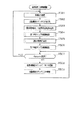
次いで、主制御装置72内のCPU101により実行される各制御処理を図8〜図15のフローチャートを参照しながら説明する。かかるCPU101の処理としては大別して、電源投入に伴い起動されるメイン処理と、定期的に(本実施の形態では2msec周期で)起動されるタイマ割込み処理と、NMI端子(ノンマスカブル端子)への停電信号の入力により起動されるNMI割込み処理とがあり、説明の便宜上、はじめにタイマ割込み処理とNMI割込み処理とを説明し、その後メイン処理を説明する。
Next, each control process executed by the
図8は、タイマ割込み処理を示すフローチャートであり、本処理は主制御装置72のCPU101により例えば2msec毎に実行される。
FIG. 8 is a flowchart showing the timer interrupt process. This process is executed by the
図8において、ステップS101では、各種入賞スイッチの読み込み処理を実行する。すなわち、主制御装置72に接続されている各種スイッチ(但し、上述した演出スイッチ76及び後述するRAM消去スイッチを除く)の状態を読み込むとともに、当該スイッチの状態を判定して検出情報(入賞検知情報)を保存する。
In FIG. 8, in step S101, various winning switch reading processes are executed. That is, the state of various switches connected to the main controller 72 (except for the
その後、ステップS102では、乱数初期値カウンタCINIの更新を実行する。具体的には、乱数初期値カウンタCINIを1インクリメントするとともに、そのカウンタ値が最大値(本実施の形態では676)に達した際0にクリアする。そして、乱数初期値カウンタCINIの更新値を、RAMの該当するバッファ領域に格納する。続くステップS103では、大当たり乱数カウンタC1、大当たり図柄カウンタC2及びリーチ乱数カウンタC3の更新を実行する。具体的には、大当たり乱数カウンタC1、大当たり図柄カウンタC2及びリーチ乱数カウンタC3をそれぞれ1インクリメントするとともに、それらのカウンタ値が最大値(本実施の形態ではそれぞれ、676,49,299)に達した際それぞれ0にクリアする。そして、各カウンタC1〜C3の更新値を、RAMの該当するバッファ領域に格納する。 Thereafter, in step S102, the random number initial value counter CINI is updated. Specifically, the random number initial value counter CINI is incremented by 1 and cleared to 0 when the counter value reaches the maximum value (676 in the present embodiment). Then, the update value of the random number initial value counter CINI is stored in the corresponding buffer area of the RAM. In the subsequent step S103, the big hit random number counter C1, the big hit symbol counter C2, and the reach random number counter C3 are updated. Specifically, the jackpot random number counter C1, the jackpot symbol counter C2 and the reach random number counter C3 are each incremented by 1, and their counter values reach the maximum values (in the present embodiment, 676, 49 and 299, respectively). Each time it is cleared to 0. Then, the updated values of the counters C1 to C3 are stored in the corresponding buffer area of the RAM.
その後、ステップS104では、作動口54への入賞に伴う始動入賞処理を実行する。この始動入賞処理を図9のフローチャートにより説明すると、ステップS201では、遊技球が作動口54に入賞(始動入賞)したか否かを作動口スイッチの検出情報により判別する。遊技球が作動口54に入賞したと判別されると、続くステップS202では、作動保留球数Nが上限値(本実施の形態では4)未満であるか否かを判別する。作動口54への入賞があり、且つ作動保留球数N<4であることを条件にステップS203に進み、作動保留球数Nを1インクリメントする。続くステップS204では、前記ステップS603で更新した大当たり乱数カウンタC1、大当たり図柄カウンタC2及びリーチ乱数カウンタC3の各値を、RAMの保留球格納エリアの空き記憶エリアのうち最初のエリアに格納する。そして、始動入賞処理の後、CPU101は本タイマ割込み処理を一旦終了する。
Thereafter, in step S104, a start winning process associated with winning in the
なお、遊技球が作動口54に入賞(始動入賞)した場合、それに伴い図柄表示装置130による図柄の変動表示が開始されることとなるが、始動入賞後、図柄が変動し図柄停止に至るまでには所定時間(例えば5秒)が経過していなければならないという制約がある。そこで、上記始動入賞処理では、始動入賞が確認された場合、各カウンタ値の格納処理(ステップS204)の後に、始動入賞後の経過時間を計るためのタイマをセットすることとしている。具体的には、上記始動入賞処理は2msec周期で実行されるため、例えば5秒の経過時間を計測するにはタイマに数値「2500」をセットし、始動入賞処理の都度、タイマ値を1ずつ減算する。このタイマ値は、その時々の各カウンタC1〜C3の値とともに、RAMの保留球格納エリアに格納され管理される。 When the game ball wins the operating opening 54 (start winning), the symbol display on the symbol display device 130 is started accordingly. However, after the start winning, the symbol changes until the symbol stops. There is a restriction that a predetermined time (for example, 5 seconds) must elapse. Therefore, in the start winning process, when the start winning is confirmed, a timer for measuring the elapsed time after the start winning is set after each counter value storing process (step S204). Specifically, since the start winning process is executed at a cycle of 2 msec, for example, in order to measure an elapsed time of 5 seconds, a numerical value “2500” is set in the timer, and the timer value is incremented by 1 for each start winning process. Subtract. This timer value is stored and managed in the reserved ball storage area of the RAM together with the values of the respective counters C1 to C3.
図10は、NMI割込み処理を示すフローチャートであり、本処理は、主制御装置72のCPU101により停電の発生等によるパチンコ機10の電源遮断時に実行される。このNMI割込みにより、電源遮断時の主制御装置72の状態がRAMのバックアップエリアに記憶される。すなわち、停電の発生等によりパチンコ機10の電源が遮断されると、停電信号SG1が停電監視回路100から主制御装置72内のCPU101のNMI端子に出力され、CPU101は実行中の制御を中断してNMI割込み処理を開始する。図10のNMI割込み処理プログラムは、主制御装置72のROMに記憶されている。停電信号SG1が出力された後所定時間は、主制御装置72の処理が実行可能となるように電源・発射制御装置92から電源供給がなされており、この所定時間内にNMI割込み処理が実行される。
FIG. 10 is a flowchart showing the NMI interrupt process. This process is executed by the
NMI割込み処理において、ステップS301では使用レジスタをRAMのバックアップエリアに退避し、続くステップS302ではスタックポインタの値を同バックアップエリアに記憶する。さらに、ステップS303では電源遮断の発生情報をバックアップエリアに設定し、ステップS304では電源が遮断されたことを示す電源遮断通知コマンドを他の制御装置に対して送信する。ステップS305ではRAM判定値を算出し、バックアップエリアに保存する。RAM判定値は、例えば、RAMの作業領域アドレスにおけるチェックサム値である。ステップS306では、RAMアクセスを禁止する。その後は、電源が完全に遮断して処理が実行できなくなるのに備え、無限ループに入る。 In the NMI interrupt processing, in step S301, the used register is saved in the RAM backup area, and in the subsequent step S302, the value of the stack pointer is stored in the backup area. Further, in step S303, information on the occurrence of power interruption is set in the backup area, and in step S304, a power interruption notification command indicating that the power has been interrupted is transmitted to another control device. In step S305, a RAM determination value is calculated and stored in the backup area. The RAM determination value is, for example, a checksum value at a RAM work area address. In step S306, RAM access is prohibited. After that, an infinite loop is entered in preparation for the case where the power supply is completely shut down and processing cannot be executed.
なお、上記のNMI割込み処理は払出制御装置91でも同様に実行され、かかるNMI割込みにより、停電の発生等による電源遮断時の払出制御装置91の状態がRAMのバックアップエリアに記憶される。停電信号SG1が出力された後所定時間は、払出制御装置91の処理が実行可能となるように電源・発射制御装置92から電源供給がなされるのも同様である。すなわち、停電の発生等によりパチンコ機10の電源が遮断されると、停電信号SG1が停電監視回路100から払出制御装置91内のCPU102のNMI端子に出力され、CPU102は実行中の制御を中断して図10のNMI割込み処理を開始する。その内容はステップS304の電源遮断通知コマンドの送信を行わない点を除き上記説明と同様である。
The NMI interrupt process is also executed in the
図11は、主制御装置72内のCPU101により実行されるメイン処理の一例を示すフローチャートであり、このメイン処理は電源投入時のリセットに伴い起動される。
FIG. 11 is a flowchart showing an example of a main process executed by the
メイン処理において、ステップS401では、電源投入に伴う初期設定処理を実行する。具体的には、スタックポインタに予め決められた所定値を設定するとともに、サブ側の制御装置(音声ランプ制御装置70、払出制御装置91等)が動作可能な状態になるのを待つために例えば1秒程度、ウェイト処理を実行する。ステップS402では、払出制御装置91に対して払出許可コマンドを送信し、続くステップS403では、RAMアクセスを許可する。
In the main process, in step S401, an initial setting process associated with power-on is executed. Specifically, in order to set a predetermined value in the stack pointer and wait for the sub-side control devices (such as the sound
その後、CPU102内のRAMに関してデータバックアップの処理を実行する。つまり、ステップS404では電源・発射制御装置92に設けたRAM消去スイッチが押されているか否かを判別し、続くステップS405ではRAMのバックアップエリアに電源遮断の発生情報が設定されているか否かを判別する。また、ステップS406ではRAM判定値を算出し、続くステップS407では、そのRAM判定値が電源遮断時に保存したRAM判定値と一致するか否か、すなわちバックアップの有効性を判別する。RAM判定値は、例えばRAMの作業領域アドレスにおけるチェックサム値である。なお、RAMの所定のエリアに書き込まれたキーワードが正しく保存されているか否かによりバックアップの有効性を判断することも可能である。
Thereafter, data backup processing is executed for the RAM in the
上述したように、本パチンコ機10では、例えばホールの営業開始時など、電源投入時にRAMデータを初期化する場合にはRAM消去スイッチを押しながら電源が投入される。従って、RAM消去スイッチが押されていれば、RAMの初期化処理(ステップS414〜S416)に移行する。また、電源遮断の発生情報が設定されていない場合や、RAM判定値(チェックサム値等)によりバックアップの異常が確認された場合も同様にRAMの初期化処理(ステップS414〜S416)に移行する。つまり、ステップS414ではRAMの使用領域を0にクリアし、続くステップS415ではRAMの初期化処理を実行する。また、ステップS416では割込み許可を設定し、後述する通常処理に移行する。
As described above, in the
一方、RAM消去スイッチが押されていない場合には、電源遮断の発生情報が設定されていること、及びRAM判定値(チェックサム値等)が正常であることを条件に、復電時の処理(電源遮断復旧時の処理)を実行する。つまり、ステップS408では電源遮断前のスタックポインタを復帰させ、ステップS409では電源遮断の発生情報をクリアする。ステップS410ではサブ側の制御装置を電源遮断時の遊技状態に復帰させるためのコマンドを送信し、ステップS411では使用レジスタをRAMのバックアップエリアから復帰させる。また、ステップS412,S413では、割込み許可/不許可を電源遮断前の状態に復帰させた後、電源遮断前の番地へ戻る。 On the other hand, if the RAM erasure switch is not pressed, processing at the time of power recovery is performed on condition that the information on occurrence of power shutdown is set and the RAM judgment value (checksum value etc.) is normal. (Processing when power is restored) is executed. That is, in step S408, the stack pointer before the power shutdown is restored, and in step S409, the information on the occurrence of power shutdown is cleared. In step S410, a command for returning the sub-side control device to the gaming state at the time of power-off is transmitted, and in step S411, the used register is returned from the RAM backup area. In steps S412 and S413, the interruption permission / non-permission is returned to the state before the power interruption, and then the address before the power interruption is returned.
次に、通常処理の流れを図12のフローチャートを参照しながら説明する。この通常処理では遊技の主要な処理が実行される。その概要として、ステップS501〜S506の処理が4msec周期の定期処理として実行され、その残余時間でステップS508,S509のカウンタ更新処理が実行される構成となっている。 Next, the flow of normal processing will be described with reference to the flowchart of FIG. In this normal process, the main process of the game is executed. As an outline, the processing of steps S501 to S506 is executed as a periodic processing with a period of 4 msec, and the counter update processing of steps S508 and S509 is executed with the remaining time.
通常処理において、ステップS501では、前回の処理で更新されたコマンド等の出力データをサブ側の各制御装置に送信する。具体的には、入賞検知情報の有無を判別し、入賞検知情報があれば払出制御装置91に対して獲得遊技球数に対応する賞球払出コマンドを送信する。賞球払出コマンドが主制御装置72から出力されたことに基づいて払出制御装置91は払出装置89を制御し、遊技球の払出が実行される。また、特定又は非特定大当たりに当選しているか否かの抽選結果、変動パターンコマンド等を音声ランプ制御装置70に対して送信する。さらに、音声ランプ制御装置70から表示制御装置110に対して、特定又は非特定大当たりに当選しているか否かの抽選結果、変動パターンコマンド等が送信されることによって図柄表示部61における図柄の変動表示が実行される。さらに、大当たり状態への移行に際しては状態移行コマンドを、可変入賞装置53の開閉に際しては開放コマンドや閉鎖コマンドを音声ランプ制御装置70に対して送信する。
In the normal process, in step S501, output data such as a command updated in the previous process is transmitted to each control device on the sub side. Specifically, the presence / absence of winning detection information is determined, and if there is winning detection information, a winning ball payout command corresponding to the number of acquired game balls is transmitted to the
次に、ステップS502では、変動種別カウンタCSの更新を実行する。具体的には、変動種別カウンタCSを1インクリメントするとともに、カウンタ値が最大値に達した際にはカウンタ値を0にクリアする。そして、変動種別カウンタCSの更新値を、RAMの該当するバッファ領域に格納する。続くステップS503では、払出制御装置91より受信した賞球計数信号や払出異常信号を読み込む。その後、ステップS504では、第1特定ランプ部63に表示される色の切り替えを行うための第1特定ランプ部制御処理を実行する。この第1特定ランプ部制御処理では、大当たり判定や図柄表示装置130による図柄の変動表示の設定、第1特定ランプ部63に配設されたLEDのスイッチのオンオフ制御などを行う。但し、第1特定ランプ部制御処理の詳細は後述する。
Next, in step S502, the variation type counter CS is updated. Specifically, the variation type counter CS is incremented by 1, and the counter value is cleared to 0 when the counter value reaches the maximum value. Then, the update value of the variation type counter CS is stored in the corresponding buffer area of the RAM. In the subsequent step S503, the prize ball counting signal and the payout abnormality signal received from the
その後、ステップS505では、遊技状態を移行させるための遊技状態移行処理を実行する。この遊技状態移行処理により、遊技状態が大当たり状態や高確率状態に移行する。 Thereafter, in step S505, a game state transition process for shifting the game state is executed. By this gaming state transition process, the gaming state transitions to a jackpot state or a high probability state.
ステップS506では、第2特定ランプ部64に表示される色の切り替え処理を行うための第2特定ランプ部制御処理を実行する。簡単に説明すると、第2特定ランプ部制御処理では、遊技球がスルーゲート55を通過したことを条件に、その都度の対応した乱数カウンタの値を取得するとともに第2特定ランプ部64に表示される色の切り替え処理を開始する。そして、取得した乱数カウンタの値により抽選を行い、当選であった場合には所定時間経過後に赤色を停止表示させるとともに、作動口54に付随する電動役物を所定時間開放する。
In step S506, a second specific lamp unit control process for switching the color displayed on the second
その後、ステップS507では、次の通常処理の実行タイミングに至ったか否か、すなわち前回の通常処理の開始から所定時間(本実施の形態では4msec)が経過したか否かを判別する。そして、次の通常処理の実行タイミングに至るまでの残余時間内において、乱数初期値カウンタCINI及び変動種別カウンタCSの更新を繰り返し実行する(ステップS508,S509)。つまり、ステップS508では、乱数初期値カウンタCINIの更新を実行する。具体的には、乱数初期値カウンタCINIを1インクリメントするとともに、そのカウンタ値が最大値に達した際0にクリアする。そして、乱数初期値カウンタCINIの更新値を、RAMの該当するバッファ領域に格納する。また、ステップS509では、変動種別カウンタCSの更新を実行する。具体的には、変動種別カウンタCSを1インクリメントするとともに、そのカウンタ値が最大値(本実施の形態では198)に達した際0にクリアする。そして、変動種別カウンタCSの更新値を、RAMの該当するバッファ領域に格納する。 Thereafter, in step S507, it is determined whether or not the execution timing of the next normal process has been reached, that is, whether or not a predetermined time (4 msec in the present embodiment) has elapsed since the start of the previous normal process. The random number initial value counter CINI and the variation type counter CS are repeatedly updated within the remaining time until the next normal processing execution timing (steps S508 and S509). That is, in step S508, the random number initial value counter CINI is updated. Specifically, the random number initial value counter CINI is incremented by 1 and cleared to 0 when the counter value reaches the maximum value. Then, the update value of the random number initial value counter CINI is stored in the corresponding buffer area of the RAM. In step S509, the variation type counter CS is updated. Specifically, the variation type counter CS is incremented by 1 and cleared to 0 when the counter value reaches the maximum value (198 in the present embodiment). Then, the update value of the variation type counter CS is stored in the corresponding buffer area of the RAM.
ここで、ステップS501〜S506の各処理の実行時間は遊技の状態に応じて変化するため、次の通常処理の実行タイミングに至るまでの残余時間は一定でなく変動する。故に、かかる残余時間を使用して乱数初期値カウンタCINIの更新を繰り返し実行することにより、乱数初期値カウンタCINI(すなわち、大当たり乱数カウンタC1の初期値)をランダムに更新することができ、同様に変動種別カウンタCSについてもランダムに更新することができる。 Here, since the execution time of each process of steps S501 to S506 changes according to the state of the game, the remaining time until the execution timing of the next normal process is not constant and varies. Therefore, by repeatedly updating the random number initial value counter CINI using the remaining time, the random number initial value counter CINI (that is, the initial value of the big hit random number counter C1) can be updated at random. Similarly, The variation type counter CS can also be updated at random.
次に、前記ステップS504の第1特定ランプ部制御処理を図13のフローチャートを参照して説明する。 Next, the first specific lamp unit control process of step S504 will be described with reference to the flowchart of FIG.
第1特定ランプ部制御処理において、ステップS601では、今現在の遊技状態が大当たり状態であるか否かを判別し、大当たり状態である場合にはそのまま本処理を終了する。大当たり状態でない場合には、ステップS602にて第1特定ランプ部63が切り替え表示中であるか否かを判別する。第1特定ランプ部63が切り替え表示中でない場合にはステップS603に進み、作動保留球数Nが0よりも大きいか否かを判別する。そして、作動保留球数Nが0である場合には、そのまま本処理を終了する。
In the first specific lamp unit control process, in step S601, it is determined whether or not the current gaming state is a jackpot state, and if it is a jackpot state, the process is terminated as it is. If it is not a big hit state, it is determined in step S602 whether or not the first
作動保留球数N>0であれば、ステップS604に進む。ステップS604では、作動保留球数Nを1減算する。ステップS605では、保留球格納エリアに格納されたデータをシフトさせる処理を実行する。このデータシフト処理は、保留球格納エリアの保留第1〜第4エリアに格納されているデータを実行エリア側に順にシフトさせる処理であって、保留第1エリア→実行エリア、保留第2エリア→保留第1エリア、保留第3エリア→保留第2エリア、保留第4エリア→保留第3エリアといった具合に各エリア内のデータがシフトされる。 If the number of active balls N> 0, the process proceeds to step S604. In step S604, 1 is subtracted from the number N of active suspension balls. In step S605, a process for shifting the data stored in the reserved ball storage area is executed. This data shift process is a process of sequentially shifting the data stored in the reserved first to fourth areas of the reserved ball storage area to the execution area side, and the reserved first area → execution area, reserved second area → The data in each area is shifted such as the first hold area, the third hold area → the second hold area, the fourth hold area → the third hold area.
ステップS606では、第1特定ランプ部63に表示される色の切り替えを開始する切り替え開始処理を実行する。具体的には、表示される色の切り替え時期を判断するためのタイマをリセットし、さらに第1特定ランプ部63に配設されたLEDのスイッチを全てオフ制御した上で、赤色光源のスイッチをオン制御する。これにより、第1特定ランプ部63には、赤色が表示される。ちなみに、大当たり状態の終了後以外であれば、切り替え表示開始前は青色光源のスイッチがオンとなっており、大当たり状態の終了後であれば、赤色光源又は緑色光源のスイッチがオンとなっている。そして、特定大当たりに移行することに当選している場合には、LEDの最終停止色が赤になるよう制御され、非特定大当たりに移行することに当選している場合には、LEDの最終停止色が緑になるよう制御される。また、いずれの大当たりに移行することにも当選していない場合には、LEDの最終停止色が青になるよう制御される。
In step S606, a switching start process for starting switching of the color displayed on the first
その後、ステップS607では、図柄表示部61による図柄の変動表示が実行される期間を決定するための変動パターンコマンド決定処理を実行する。
Thereafter, in step S607, a variation pattern command determination process for determining a period during which the symbol variation display by the
この変動パターンコマンド決定処理にて図柄の変動表示が開始されてからその図柄の変動表示が終了するまでの期間が決定される。パチンコ機10では、図柄の変動表示が開始されてから終了するまでを1遊技回としており、変動パターンコマンド決定処理では、1遊技回の期間を決定しているともいえる。なお、変動パターンコマンドは、その遊技回にて参照された各カウンタC1〜C3及び変動種別カウンタCSから決定されるものであり、この変動パターン決定処理にて決定された期間に亘りステップS606における切り替え処理が実行されることとなる。なお、各カウンタC1〜C3、変動種別カウンタCSの値と変動パターンとの関係は、図示しないテーブルにより予め規定されている。この変動パターンコマンドが音声ランプ制御装置70に出力され、当該コマンドが音声ランプ制御装置70から表示制御装置110に出力されることによって表示制御装置110は1遊技回の期間を把握することができる。例えば、変動種別カウンタCSの値がスーパーリーチを実行するものであった場合、変動パターンコマンド決定処理にてスーパーリーチを実行することが可能な期間が選択される。ここで決定された変動パターンコマンドは上述した通常処理におけるステップS501の外部出力処理にて音声ランプ制御装置70に出力される。この際、変動パターンコマンドに合わせて、大当たり乱数カウンタC1,大当たり種別カウンタC2の値に基づいた抽選結果も出力する。これにより、音声ランプ制御装置70では、大当たり抽選に当選したか否かを認識できるとともに、大当たり抽選に当選していた場合にその当選結果が特定大当たりであるか非特定大当たりであるかを認識できる。
In this variation pattern command determination process, the period from the start of the symbol variation display to the termination of the symbol variation display is determined. In the
一方、ステップS602がYESの場合、すなわち第1特定ランプ部63が切り替え表示中である場合にはステップS608に進み、先の変動パターン決定処理(ステップS607)にて決定された期間を経過したか否かを判別する。切り替え表示時間を経過していないと判別した場合には、ステップS609にて表示色切り替え処理を実行する。この表示色切り替え処理により、各光源のスイッチがオンオフ制御され、第1特定ランプ部63に表示される色が切り替えられる。
On the other hand, if step S602 is YES, that is, if the first
ステップS607にて決定された期間が経過したとステップS608において判定した場合には、ステップS610において切り替え終了処理を実行する。この切り替え終了処理は、最終表示させる色の光源をオン制御するための処理である。具体的には、まず現在オンとなっている光源のスイッチをオフ制御する。その後、先の変動開始処理においてセットした表示フラグを確認し、表示フラグと対応する光源のスイッチをオン制御する。すなわち、特定大当たりの場合には赤色光源のスイッチをオン制御し、非特定大当たりの場合には緑色光源のスイッチをオン制御し、外れの場合には青色光源のスイッチをオン制御する。これにより、大当たりの抽選結果に応じた表示色が第1特定ランプ部63に最終表示されることとなる。なお、ここで設定された表示色は、次回の切り替え開始処理まで維持される。この切り替え終了処理を行った後、S611では切り替え表示時間が経過したことを示す変動終了コマンドを設定し、本処理を終了する。
If it is determined in step S608 that the period determined in step S607 has elapsed, a switching end process is executed in step S610. This switching end process is a process for turning on the light source of the color to be finally displayed. Specifically, first, the switch of the light source that is currently turned on is turned off. Thereafter, the display flag set in the previous variation start process is confirmed, and the light source switch corresponding to the display flag is turned on. That is, the switch of the red light source is turned on in the case of a specific jackpot, the switch of the green light source is turned on in the case of a non-special jackpot, and the switch of the blue light source is turned on in the case of a failure. As a result, the display color corresponding to the lottery lottery result is finally displayed on the first
次に、前記ステップS505の遊技状態移行処理を図14のフローチャートを参照して説明する。 Next, the gaming state transition processing in step S505 will be described with reference to the flowchart of FIG.
先ず、ステップS701では、現在の遊技状態が大当たり状態か否かを判別する。大当たり状態でない場合にはステップS702に進み、大当たり図柄の組み合わせが最終停止表示される大当たり変動が終了したか否かを判別する。具体的には、保留球格納エリアの実行エリアに格納されている大当たり乱数カウンタC1の値と、変動パターン決定処理にて決定された期間の経過とに基づいて判別する。大当たり変動が終了していない場合にはそのまま本処理を終了し、大当たり変動が終了した場合には、ステップS703〜ステップS706に示す大当たり状態開始処理を行う。大当たり状態開始処理では、ステップS703において、RAMに設けられたラウンドカウンタRCに15をセットする。ラウンドカウンタRCは、可変入賞装置53が開放された回数をカウントするためのカウンタである。また、では可変入賞装置53を開閉させる開閉タイミングを計るためのタイマに5000(すなわち10秒)をセットし、さらにRAMに設けられた大当たりフラグ格納エリアに大当たりフラグをセットする。
First, in step S701, it is determined whether or not the current gaming state is a jackpot state. If it is not a jackpot state, the process proceeds to step S702, and it is determined whether or not the jackpot fluctuation in which the combination of jackpot symbols is finally stopped and displayed has ended. Specifically, the determination is made based on the value of the jackpot random number counter C1 stored in the execution area of the reserved ball storage area and the passage of the period determined by the variation pattern determination process. If the big hit variation has not ended, the processing is terminated as it is, and if the big hit variation has ended, the big hit state start processing shown in steps S703 to S706 is performed. In the big hit state starting process, in step S703, 15 is set to the round counter RC provided in the RAM. The round counter RC is a counter for counting the number of times the variable winning
続く、ステップS704にて特定大当たりか否かを判定する。この判定には大当たり種別カウンタC2を用いる。特定大当たりであった場合には、ステップS705に進み、RAMに設けられた特定フラグ格納エリアに特定フラグをセットする。 Subsequently, in step S704, it is determined whether or not a specific big hit has occurred. For this determination, a jackpot type counter C2 is used. If it is a special big hit, the process proceeds to step S705, and a specific flag is set in a specific flag storage area provided in the RAM.
ステップS704にて特定大当たりではないと判定された場合、又はステップS705にて特定フラグをセットした場合、ステップS706に進み、状態移行コマンドを設定して本処理を終了する。ここで、状態移行コマンドとは表示制御装置110に対して送信されるものである。表示制御装置110は、当該コマンドを受信することにより、大当たり状態に移行したことを認識するとともに、大当たり状態に移行したことを示すオープニング動画を図柄表示装置130に表示させるべく表示制御を開始する。なお、セットされたタイマ値は、タイマ割込み処理の都度、すなわち2msec周期で1ずつ減算される。
If it is determined in step S704 that it is not a special big hit, or if a specific flag is set in step S705, the process proceeds to step S706, a state transition command is set, and this process is terminated. Here, the state transition command is transmitted to the
一方、ステップS701において遊技状態が大当たり状態である場合には、ステップS707に進み、可変入賞装置53を開放又は閉鎖するための可変入賞装置開閉処理を行う。
On the other hand, if the gaming state is a jackpot state in step S701, the process proceeds to step S707, and variable winning device opening / closing processing for opening or closing the variable winning
可変入賞装置開閉処理では、図15のフローチャートに示す通り、先ずステップS801にて可変入賞装置53を開放中であるか否かを判定する。可変入賞装置53を開放中でない場合には、ステップS802にてラウンドカウンタRCの値が0か否かを判別するとともに、ステップS803にてタイマの値が0か否かを判別する。ラウンドカウンタRCの値が0である場合又はタイマの値が0でない場合には、そのまま本処理を終了する。一方、ラウンドカウンタRCの値が0でなく且つタイマの値が0である場合には、ステップS804に進み、可変入賞装置53を開放する。続くステップS805では、可変入賞装置53に入賞した遊技球の数を記憶するための入賞カウンタPCに0をセットする。その後、ステップS806ではタイマに14750(すなわち29.5秒)をセットするとともにステップS807にて開放コマンドをセットし、本処理を終了する。この結果、可変入賞装置53が最大29.5秒間開放されることとなる。ここで、開放コマンドは、音声ランプ制御装置70を介して表示制御装置110に対して送信されるものである。表示制御装置110は、当該コマンドを受信することにより、可変入賞装置53が開放されたことを認識し、可変入賞装置53が開放されている間に表示すべき動画を図柄表示装置130に表示させるべく表示制御を開始する。
In the variable winning device opening / closing process, as shown in the flowchart of FIG. 15, it is first determined in step S801 whether or not the variable winning
また、ステップS801にて可変入賞装置53が開放中である場合にはステップS808に進み、タイマの値が0か否かを判別する。タイマの値が0でない場合、ステップS809にて可変入賞装置53に遊技球が入賞したか否かを判別する。可変入賞装置53へ遊技球が入賞していない場合には、そのまま本可変入賞装置開閉処理を終了する。一方、可変入賞装置53へ遊技球が入賞した場合には、ステップS810にて入賞カウンタPCの値を1加算した後にステップS811にて入賞カウンタPCの値が10か否かを判別し、10でない場合にはそのまま本処理を終了する。
If the variable winning
ステップS808にてタイマの値が0の場合、又はステップS811にて入賞カウンタPCの値が10の場合には、可変入賞装置53の閉鎖条件が成立したことを意味する。かかる場合にはステップS812にて可変入賞装置53を閉鎖する。続くステップS813ではラウンドカウンタRCの値を1減算し、ステップS814にてラウンドカウンタRCの値が0か否かを判別する。ラウンドカウンタRCの値が0でない場合にはステップS815にてタイマに1000(すなわち2秒)をセットし、ラウンドカウンタRCの値が0である場合にはステップS816にてタイマに5000(すなわち10秒)をセットする。その後、ステップS817にて閉鎖コマンドをセットし、本処理を終了する。ここで、閉鎖コマンドとは、音声ランプ制御装置70を介して表示制御装置110に対して送信されるものである。表示制御装置110は、当該コマンドを受信することにより、1回のラウンドが終了したことを認識し、例えば次回のラウンド数等を教示する開放前動画や、大当たり状態が終了したことを示すエンディング動画を図柄表示装置130に表示させるべく表示制御を開始する。
If the timer value is 0 in step S808, or if the value of the winning counter PC is 10 in step S811, it means that the closing condition of the variable winning
可変入賞装置開閉処理の後、ステップS708ではラウンドカウンタRCの値が0か否かを判別するとともに、ステップS709にてタイマの値が0か否かを判別する。そして、ラウンドカウンタRC又はタイマの値の少なくとも一方が0でない場合には、そのまま本処理を終了する。一方、ラウンドカウンタRC及びタイマの値が0である場合には、ステップS710に進み、大当たり状態を終了させる大当たり状態終了処理として大当たりフラグ格納エリアにセットされた大当たりフラグをクリアする。従って、大当たり状態下では、ラウンドカウンタRCにセットされた回数(すなわち15回)の大入賞口の連続開放が許容される。 After the variable winning device opening / closing process, it is determined whether or not the value of the round counter RC is 0 in step S708, and whether or not the value of the timer is 0 in step S709. If at least one of the values of the round counter RC or the timer is not 0, this processing is terminated as it is. On the other hand, when the values of the round counter RC and the timer are 0, the process proceeds to step S710, and the jackpot flag set in the jackpot flag storage area is cleared as a jackpot state end process for ending the jackpot state. Therefore, under the big hit state, the consecutive opening of the big winning opening is allowed for the number of times set in the round counter RC (that is, 15 times).
大当たり状態終了処理を行った後、ステップS711〜ステップS715では状態移行処理を行う。すなわち、ステップS711では、特定フラグがセットされているか否かを判別する。特定フラグがセットされている場合には特定大当たりが発生したことを意味するため、ステップS712に進み、それ以降の遊技状態を高確率状態とする高確率状態移行処理を行う。そして、ステップS713に進み、特定フラグをクリアするとともに高確率状態移行コマンドセットし、本遊技状態移行処理を終了する。また、特定フラグがセットされていない場合には非特定大当たりが発生したことを意味するため、ステップS714にてそれ以降の遊技状態を通常状態とする通常状態移行処理を行う。そして、ステップS715に進み、通常状態移行コマンドをセットし、本遊技状態移行処理を終了する。高確率状態又は通常状態移行コマンドが出力されたことに基づいて、音声ランプ制御装置70及び表示制御装置110では、遊技状態が移行したことを認識する。
After the big hit state end process is performed, a state transition process is performed in steps S711 to S715. That is, in step S711, it is determined whether or not a specific flag is set. If the specific flag is set, it means that a specific jackpot has occurred, so the process proceeds to step S712, and a high probability state transition process is performed in which the gaming state thereafter is set to a high probability state. In step S713, the specific flag is cleared and a high probability state transition command is set, and the gaming state transition process is terminated. Further, when the specific flag is not set, it means that a non-specific big hit has occurred, and therefore, in step S714, normal state transition processing is performed in which the gaming state thereafter is set to the normal state. Then, the process proceeds to step S715, the normal state transition command is set, and the gaming state transition process is terminated. Based on the output of the high probability state or normal state transition command, the sound
次に、音声ランプ制御装置70にて実行される処理について説明する。先ず、パチンコ機10に電源が投入された場合に、音声ランプ制御装置70にて実行される立ち上げ処理について図16のフローチャートを用いて説明する。
Next, processing executed by the sound
ステップS901にて初期設定処理を実行する。この初期設定処理では、スタックポインタの初期設定を実行する。ステップS902では、停電処理フラグ(後述する音声ランプ制御装置70のメイン処理におけるステップS1011にてセットされるフラグ)が停電処理フラグ格納エリアにセットされているか否かを判定する。この処理により、今回の立ち上げ処理が通常の電源投入によって実行されているものなのか、或いは、瞬間的な電圧降下によって実行されているものなのかを判定できる。停電処理フラグがセットされていなかった場合、ステップS903に進み、RAM115のデータが破壊されているか否かを判定する。ステップS903にてRAM115のデータが破壊されていた場合、ステップS904に進みRAM115の初期化処理を実行する。
In step S901, an initial setting process is executed. In this initial setting process, the stack pointer is initialized. In step S902, it is determined whether or not a power failure processing flag (a flag set in step S1011 in the main processing of the sound
なお、RAM115におけるデータの破壊の有無は、所定領域に記憶されているデータをチェックし、そのデータが所定値であれば破壊がないと判定し、当該所定値でなかった場合にはデータの破壊ありと判定する。すなわち、その所定領域は、RAM115におけるデータ破壊の有無の判定に用いるための記憶領域として機能している。また、パチンコ機10の電源が完全に遮断されていた状態から電源が投入された場合、上記所定領域には所定値が入力されておらず(電源遮断によりRAM115の値は失われる)、ステップS903にてRAM115のデータの破壊ありと判定するようになっている。
Whether or not the data is destroyed in the
ステップS902にて停電処理フラグがセットされていた場合、又は、ステップS904にてRAM115の初期化を実行した場合、ステップS905に進み、RAM115が正常に値を記憶できるか否かを判定する。RAM115における一の領域に、例えば、「0100」を入力し、当該一の領域に記憶されている値を読み出し、その値が「0100」であるか否かを判定する。記憶されている値が「0100」であった場合にはRAM115が正常に値を記憶できると判定する。なお、RAM判定値(チェックサム値等)により記憶保持されたデータよりRAM115が正常に値を記憶できるかを判定するようにしてもよい。
If the power failure processing flag has been set in step S902, or if initialization of the
なお、上述した瞬間的な電圧降下の場合であっても、停電処理フラグがクリアされた後(音声ランプ制御装置70のメイン処理におけるステップS1013)に電源供給が復帰した場合にはステップS902にて否定判定される。この場合にRAM初期化処理を実行するとそれまでの処理が中止されてしまい遊技を進行する上で不具合が生じてしまう。ステップS903の処理は、瞬間的な電圧降下であって停電処理フラグがクリアされている場合にRAM初期化処理を実行させないための処理である。 Even in the case of the instantaneous voltage drop described above, if the power supply is restored after the power failure processing flag is cleared (step S1013 in the main processing of the sound lamp control device 70), in step S902 Negative determination is made. In this case, if the RAM initialization process is executed, the process up to that point is interrupted, causing a problem in progressing the game. The process of step S903 is a process for preventing the RAM initialization process from being executed when the voltage drop is instantaneous and the power failure process flag is cleared.
ステップS905にてRAM115が正常に値を記憶できないと判定した場合、ステップS906に進み、RAM115に異常が発生していることを報知するようランプ部23〜25及びスピーカ部26を制御して無限ループに突入する。
If it is determined in step S905 that the
ステップS903にてRAM115のデータが破壊されていなかった場合、又はステップS905にてRAM115が正常に値を記憶できると判定した場合、ステップS907に進みRAM初期設定処理を実行する。RAM初期設定処理では、特定演出フラグ設定処理とID情報設定処理とRTCタイマ設定処理とを実行する。それぞれの処理について説明する。
If it is determined in step S903 that the data in the
特定演出フラグ設定処理では、演出スイッチ76が操作されているか否かを判定する。演出スイッチ76が操作されている場合には、RAM115に設けられた演出不実行フラグ格納エリアに演出不実行フラグをセットする。
In the specific effect flag setting process, it is determined whether or not the
ID情報設定処理では、ID情報設定装置75に設定されているID情報を取得し、その取得したID情報をRAM115に設けられたID情報格納エリアに記憶する。本実施形態では、ID情報設定装置75にはID情報入力手段としてのID情報設定スイッチが設けられており、そのスイッチを切替えることによって設定されているID情報を変更することが可能となる。スイッチの切替によってID情報を設定できるため、パチンコ機10に電源を投入する毎にID情報設定装置75にID情報を設定する必要がない。
In the ID information setting process, ID information set in the ID
なお、ID情報設定スイッチに代えてID情報設定装置75にID情報を入力する入力キーが設けられており、入力キーの操作により入力されたID情報を設定する構成も考えられる。この場合、パチンコ機10の電断時において一度入力したID情報をID情報設定装置75が記憶可能にしておけば、パチンコ機10に電源が投入される毎にID情報をID情報設定装置75に入力する必要がなくなる。
Note that an input key for inputting ID information is provided in the ID
RTCタイマ設定処理では、RTC120より現在の年月日情報及び時刻情報を取得する年月日情報取得処理及び時刻情報取得処理を実行する。その取得した年月日情報及び時刻情報は、RAM115に設けられたタイマカウンタ115aにセットされる。
In the RTC timer setting process, a date information acquisition process and a time information acquisition process for acquiring current date information and time information from the
なお、演出不実行フラグ、ID情報、年月日情報及び時刻情報は後述する特定演出を実行するか否かに用いられるものであり、演出不実行フラグがセットされていた場合には特定演出が実行されない。このため、演出不実行フラグをセットした場合にはID情報、年月日情報及び時刻情報を取得しない構成としてもよい。 The effect non-execution flag, ID information, date information, and time information are used to determine whether or not to execute a specific effect described later. When the effect non-execution flag is set, the specific effect is displayed. Not executed. For this reason, when an effect non-execution flag is set, it is good also as a structure which does not acquire ID information, date information, and time information.
ステップS907にてRAM初期設定処理を実行した場合、ステップS908に進み、割込み許可を設定する。割込み許可を設定したら本立ち上げ処理を終了し、メイン処理へと移行する。割込み許可が設定されることにより、後述するタイマ割込み処理の実行が開始される。 When the RAM initial setting process is executed in step S907, the process proceeds to step S908, and interrupt permission is set. When interrupt permission is set, this start-up process is terminated and the process proceeds to the main process. When the interrupt permission is set, execution of a timer interrupt process described later is started.
音声ランプ制御装置70にて実行されるメイン処理について図17のフローチャートを用いて説明する。
The main process executed by the sound
先ず、ステップS1001にてメイン処理が開始されてから1msecが経過したか否かを判定する。1msecが経過していた場合、ステップS1002に進み、電源投入報知処理を行いその後にデモ画面表示処理を実行する。 First, in step S1001, it is determined whether 1 msec has elapsed since the start of the main process. If 1 msec has elapsed, the process proceeds to step S1002, where a power-on notification process is performed, and then a demonstration screen display process is performed.
電源投入報知処理は、パチンコ機10に電源が投入された場合に所定の期間(例えば、30秒)に亘り、電源が投入されたことの報知を行う処理である。その報知は、ランプ部23〜25及びスピーカ部26により行われる。電源投入報知処理では、報知を実行するようコマンドをセットする。当該コマンドは外部出力処理(本メイン処理におけるステップS1007)にて出力される。当該コマンドが出力されることにより、ランプ部23〜25及びスピーカ部26にてその報知が実行される。なお、図柄表示装置130を用いて電源投入時の報知を実行するようにしてもよい。また、電源投入時でなければ、電源投入報知処理を行うことなくデモ画面表示処理を実行する。
The power-on notification process is a process for notifying that the power has been turned on for a predetermined period (for example, 30 seconds) when the
デモ画面表示処理は、パチンコ機10が遊技されていない期間が所定期間となった場合に表示制御装置110に出力するコマンドをセットする処理である。当該コマンドは外部出力処理(本メイン処理におけるステップS1007)にて表示制御装置110に出力される。表示制御装置110は、当該コマンドを受信した場合に図柄表示装置130にてデモ画面を表示する。
The demonstration screen display process is a process of setting a command to be output to the
デモ画面表示処理を実行したらステップS1003に進み、演出実行管理処理を実行する。演出実行管理処理は、主制御装置72から出力される変動パターンコマンド等に基づいて演出態様を設定する処理である。演出実行管理処理では、当該変動パターンコマンド等に基づいた図柄表示装置130における図柄変動表示態様をコマンドとしてセットする。また、演出実行管理処理では、ランプ部23〜25の点灯態様及びスピーカ部26の音声出力態様を設定し、その設定内容をレジスタに記憶する。
When the demonstration screen display process is executed, the process advances to step S1003 to execute the effect execution management process. The effect execution management process is a process of setting an effect mode based on a variation pattern command or the like output from the
なお、演出実行管理処理では、図柄表示装置130の図柄変動表示態様、ランプ部23〜25の点灯態様及びスピーカ部26の音声出力態様を設定する場合(図柄変動表示態様はコマンドをセットする場合)にカウンタを用いる。そのカウンタは、後述するカウンタ更新処理(音声ランプ制御装置70のメイン処理におけるステップS1008)にて更新されるものである。そのカウンタに基づいて各態様を設定することにより、主制御装置72から変動パターンコマンドを受信した場合に実行される演出が一義的なものとなることを抑制し、変動パターンコマンドを受信した場合に実行される演出に不規則性を持たせることが可能となる。
In the effect execution management process, when the symbol variation display mode of the symbol display device 130, the lighting mode of the
ステップS1003にて演出実行管理処理を実行したらステップS1004に進み、特定演出フラグが特定演出フラグ格納エリアにセットされているか否かを判定する。特定演出フラグがセットされていた場合にはステップS1005に進み、特定演出実行管理処理を実行する。特定演出実行管理処理は、後述する特定演出フラグ(音声ランプ制御装置70によるタイマ割込み処理にて説明する)がRAM115に設けられた特定演出フラグ格納エリアにセットされている場合に、その特定演出フラグに基づいて演出態様を設定する処理である。特定演出実行管理処理では、当該特定演出フラグに基づいた図柄表示装置130における表示態様をコマンド(特定演出フラグコマンド)としてセットする。また、ランプ部23〜25の点灯態様及びスピーカ部26における音声出力の態様を設定し、その設定内容をレジスタに記憶する。
If the production execution management process is executed in step S1003, the process proceeds to step S1004, and it is determined whether or not the specific production flag is set in the specific production flag storage area. If the specific effect flag is set, the process proceeds to step S1005 to execute a specific effect execution management process. The specific effect execution management process is performed when a specific effect flag (described later in the timer interrupt process by the sound lamp control device 70) is set in the specific effect flag storage area provided in the
ステップS1004にて特定演出フラグが特定演出フラグ格納エリアにセットされていなかった場合、又はステップS1005にて特定演出実行管理処理を実行した場合、ステップS1006に進み、スピーカ部及びランプ部編集処理を実行する。スピーカ部及びランプ部編集処理では、ステップS1003の演出実行管理処理にて設定された音声出力態様及び点灯態様をレジスタから読込むとともに、ステップS1005の特定演出実行管理処理にて音声出力態様及び点灯態様が設定されていた場合にはその設定内容をレジスタから読込む。そして、その読込んだ設定内容を合成して実際にランプ部23〜25及びスピーカ部26におけるそれぞれの表示態様を決定し、それらをコマンドとしてセットする。
If the specific effect flag is not set in the specific effect flag storage area in step S1004, or if the specific effect execution management process is executed in step S1005, the process proceeds to step S1006 to execute the speaker unit and lamp unit editing process. To do. In the speaker unit and lamp unit editing process, the voice output mode and lighting mode set in the effect execution management process in step S1003 are read from the register, and the voice output mode and lighting mode are set in the specific effect execution management process in step S1005. If set, read the setting from the register. Then, the setting contents that have been read are combined to actually determine the respective display modes in the
なお、詳細な説明は省略するが、スピーカ部及びランプ部編集処理では、ステップS1003の演出実行管理処理にて設定された点灯態様及び音声出力態様よりも、ステップS1005の特定演出実行管理処理にて点灯態様及び音声出力態様が、実際のランプ部23〜25及びスピーカ部26における表示態様として優先して決定されるようになっている。すなわち、特定演出実行管理処理にて点灯態様及び音声出力態様が設定されている場合、その点灯態様及び音声出力態様を阻害しない場合に、演出実行管理処理にて設定された点灯態様及び音声出力態様が実際のランプ部23〜25及びスピーカ部26として決定されるようになっている。換言すると、特定演出実行管理処理にて設定された点灯態様及び音声出力態様に、演出管理実行処理にて設定された点灯態様及び音声出力態様を可能な限り追加しているともいえる。
In addition, although detailed description is omitted, in the speaker unit and lamp unit editing process, the specific effect execution management process in step S1005 is more effective than the lighting mode and sound output mode set in the effect execution management process in step S1003. The lighting mode and the sound output mode are preferentially determined as display modes in the
また、特定演出実行管理処理における点灯態様及び音声出力態様、表示制御装置110に出力するコマンドについては、音声ランプ制御装置70に設けられたROM113に複数種記憶されており、セットされた特定演出フラグに基づいた内容が参照される。特定演出フラグは、特定演出実行管理処理を実行した場合にクリアされるようになっている。
Further, the lighting mode and sound output mode in the specific effect execution management process, and the commands output to the
ステップS1006にてスピーカ部及びランプ部編集処理を実行した場合、ステップS1007に進み外部出力処理を実行する。外部出力処理では、ステップS1002〜ステップS1006にてセットされたコマンドを出力する。これにより、ステップS1002〜ステップS1006にて決定された内容がランプ部23〜25、スピーカ部26及び表示制御装置110にて反映される。
When the speaker unit and lamp unit editing process is executed in step S1006, the process proceeds to step S1007, and the external output process is executed. In the external output process, the command set in steps S1002 to S1006 is output. Accordingly, the contents determined in steps S1002 to S1006 are reflected in the
ステップS1001にて1msecが経過していないと判定した場合、又はステップS1007にて外部出力処理を実行した場合、ステップS1008に進みカウンタ更新処理を実行する。カウンタ更新処理では、音声ランプ制御装置70に設けられた複数のカウンタ(例えば、ステップS1003における演出実行管理処理におけるランプ部23〜25の点灯態様、スピーカ部26の音声出力態様の決定に用いるカウンタ)が更新される。ステップS1001にて否定判定された場合にもカウンタ更新処理を実行することにより、カウンタ更新処理を実行するタイミングに不規則性を持たせるとともに、短い周期にてカウンタ更新処理を実行することが可能となる。
If it is determined in step S1001 that 1 msec has not elapsed, or if an external output process is executed in step S1007, the process proceeds to step S1008 and a counter update process is executed. In the counter update process, a plurality of counters provided in the audio lamp control device 70 (for example, counters used for determining the lighting mode of the
カウンタ更新処理を実行したらステップS1009に進み、コマンド受信処理を実行する。コマンド受信処理にて主制御装置72からコマンドを受信した場合、音声ランプ制御装置70に対応したコマンドであれば当該コマンドに対応した処理を実行する(例えば、受信したコマンドが変動パターンコマンドであった場合には、ステップS1003にて変動表示態様を決定する)。また、そのコマンドが表示制御装置110に対応したものであれば当該コマンドをRAM115に記憶し、外部出力処理にて表示制御装置110に当該コマンドを出力する。
If the counter update process is executed, the process advances to step S1009 to execute a command reception process. When a command is received from the
コマンド受信処理を実行したらステップS1010に進み、RAM115に設けられた停電フラグ格納エリアに停電フラグがセットされているか否かを判定する。停電フラグは、ステップS1009のコマンド受信処理にて主制御装置72から停電コマンドを受信した場合にセットされるものである。停電フラグがセットされていなかった場合、ステップS1001に戻る。
When the command reception process is executed, the process advances to step S1010 to determine whether or not a power failure flag is set in the power failure flag storage area provided in the
一方、ステップS1010にて停電フラグがセットされていた場合、ステップS1011に進み、停電処理フラグをセットする。停電処理フラグをセットしたら、ステップS1012に進み、停電処理を実行する。停電処理については周知の構成のため説明を省略する(音声ランプ制御装置70によるスピーカ部26の処理の中止等を行う)。停電処理を実行したらステップS1013に進み停電処理フラグをクリアした後に無限ループに入る。
On the other hand, if the power failure flag is set in step S1010, the process proceeds to step S1011 and the power failure processing flag is set. If the power failure processing flag is set, the process proceeds to step S1012 to execute power failure processing. Description of the power failure processing is omitted because it is a known configuration (the processing of the
次に、音声ランプ制御装置70による立ち上げ処理のステップS908にて割込み許可が設定された場合に実行されるタイマ割込み処理について図18のフローチャートを用いて説明する。タイマ割込み処理は2msec毎にメイン処理に割り込んで実行される処理である。
Next, timer interrupt processing executed when interrupt permission is set in step S908 of the startup processing by the sound
ステップS1101では、演出不実行フラグ格納エリアに演出不実行フラグがセットされているか否かを判定する(音声ランプ制御装置70による立ち上げ処理のステップS907でセットされていたか否かを判定する)。演出不実行フラグがセットされていた場合、本タイマ割込み処理を終了する。 In step S1101, it is determined whether or not an effect non-execution flag is set in the effect non-execution flag storage area (determines whether or not it is set in step S907 of the startup process by the sound lamp control device 70). If the production non-execution flag is set, the timer interruption process is terminated.
ステップS1101にて演出不実行フラグセットされていなかった場合、ステップ1102におけるタイマカウンタ更新処理を実行する。タイマカウンタ更新処理について説明するに先立ち、本パチンコ機10におけるタイマカウンタ115aについて図19を用いて説明する。
If the performance non-execution flag has not been set in step S1101, the timer counter update process in
タイマカウンタ115aには、年情報、月情報、日情報、時情報、分情報及び秒情報格納エリア115b〜115gがそれぞれ設けられている。それぞれの格納エリアには第1情報格納エリアと第2情報格納エリアとが設けられており、この2種類の格納エリアを用いてそれぞれの情報を記憶している。第1,第2情報格納エリアには、それぞれ4ビットの記憶領域が設けられている。その4ビットの記憶領域に年,月,日,分情報がそれぞれ2進数にて記憶されている。そして、第1情報格納エリアは10進数の10の位を表し、第2情報格納エリアは10進数の1の位をそれぞれ表している。この場合、2進数の情報が記憶されている第1,第2情報格納エリアを、2桁の10進数として扱うことが可能となる。すなわち、タイマカウンタ115aは、複数種記憶されている2進数の値を10進数として表現できる2進化10進数機能を有しているといえる(所謂、BCDにて情報を記憶している)。
The
例えば、図19に示す年情報格納エリア115bの第1情報格納エリアには「0000」が格納されており、第2情報格納エリアには「1000」が格納されている。よって、年情報は「08」となる。これにより、現在の西暦が2008年であることが特定される。 For example, “0000” is stored in the first information storage area of the year information storage area 115b shown in FIG. 19, and “1000” is stored in the second information storage area. Therefore, the year information is “08”. Thereby, it is specified that the current year is 2008.
同様に図19に示す月情報格納エリア115cには、第1,第2情報格納エリアにそれぞれ「0000」、「0001」が格納されているため、月情報は「01」となる。これにより、現在の月が1月であることが特定される。日情報格納エリア115dも同様に、第1,第2情報格納エリアにはそれぞれ「0011」、「0001」が格納されており、日情報が「31」となり、日付が31日であることが特定される。時,分及び秒情報も同様に特定され、図19に示している数値の場合、現在の時刻が14時55分07秒であることが特定される。本実施形態の場合、年情報、月情報、日情報、時情報、分情報及び秒情報がそれぞれ異なる格納エリアに記憶されているため、処理に必要な情報のみを取得して年月日及び時間情報に対応した演出を行うことができる。また、タイマカウンタ115aには減算カウンタエリア115hが設けられており、この減算カウンタエリア115hを用いてタイマカウンタ更新処理を実行している。
Similarly, in the month information storage area 115c shown in FIG. 19, “0000” and “0001” are stored in the first and second information storage areas, respectively, so that the month information is “01”. Thereby, it is specified that the current month is January. Similarly, in the day information storage area 115d, “0011” and “0001” are stored in the first and second information storage areas, respectively, the day information is “31”, and the date is 31 days. Is done. The hour, minute, and second information is similarly specified. In the case of the numerical value shown in FIG. 19, it is specified that the current time is 14:55:07. In the case of this embodiment, year information, month information, day information, hour information, minute information and second information are stored in different storage areas. An effect corresponding to the information can be performed. The
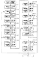
タイマ割込み処理におけるステップS1102のタイマカウンタ更新処理について図20のフローチャートを用いて説明する。 The timer counter update process in step S1102 in the timer interrupt process will be described with reference to the flowchart of FIG.
ステップS1201では減算カウンタエリア115hの値を1ディクリメントする。減算カウンタエリア115hの値を1ディクリメントしたらステップS1202に進み、減算カウンタエリア115hの値が0であるか否かを判定する。減算カウンタエリア115hの値が0でなかった場合、本タイマカウンタ更新処理を終了する。減算カウンタエリア115hの値が0であった場合、ステップS1203に進み、減算カウンタエリア115hに500をセットする(2進数で「111110100」)。 In step S1201, the value of the subtraction counter area 115h is decremented by 1. When the value of the subtraction counter area 115h is decremented by 1, the process proceeds to step S1202, and it is determined whether or not the value of the subtraction counter area 115h is 0. When the value of the subtraction counter area 115h is not 0, the timer counter update process is terminated. If the value of the subtraction counter area 115h is 0, the process proceeds to step S1203, and 500 is set in the subtraction counter area 115h (binary number “111110100”).
減算カウンタエリア115hは、500から数字が1ずつディクリメントされるため、ステップS1201の処理が500回実行された場合に、ステップS1202にて肯定判定する。タイマ割り込み処理が2msec周期にて実行されるため、タイマカウンタ更新処理も2msec周期にて実行される。ステップS1201の処理が2msec周期にて500回実行された場合にステップS1202にて肯定判定するため、ステップS1202の処理では1秒(500×0.002)周期にて肯定判定される。ステップS1201、ステップS1202の処理を実行することにより、1秒の経過を好適に計測できる。すなわち、秒情報格納エリア115gの第2情報の値は、1秒周期にてインクリメントされる(ステップS1204)こととなる。 Since the subtraction counter area 115h is decremented by 1 from 500, an affirmative determination is made in step S1202 when the process of step S1201 is executed 500 times. Since the timer interrupt process is executed at a cycle of 2 msec, the timer counter update process is also executed at a cycle of 2 msec. When the process of step S1201 is executed 500 times at a cycle of 2 msec, an affirmative determination is made at step S1202. Therefore, an affirmative determination is made at a cycle of 1 second (500 × 0.002) in the process of step S1202. By executing the processing of step S1201 and step S1202, the passage of 1 second can be suitably measured. That is, the value of the second information in the second information storage area 115g is incremented at a cycle of 1 second (step S1204).
減算カウンタエリア115hに値をセットしたらステップS1204に進み、秒情報格納エリア115gの第2情報格納エリアの値を1インクリメントする。ステップS1204の処理はステップS1204にて肯定判定した場合に実行されるため、1秒が経過した場合に秒情報格納エリア115gの値が加算される。秒情報格納エリア115gの第2情報格納エリアの値を1インクリメントしたらステップS1205に進み、秒情報格納エリア115gの第2情報格納エリアの値が「1010」か否かを判定する。その第2情報格納エリアの値が「1010」でなかった場合、本タイマカウンタ更新処理を終了する。秒情報格納エリア115gの第2情報の値が「1010」であるかとは、10進数で10であるか否かを判定しており、10進数に換算した場合に位があがるか否かを判定している。秒情報格納エリア115gの第2情報格納エリアの値は、1秒周期にてインクリメントされるため、10秒周期にてステップS1205では肯定判定される。 When a value is set in the subtraction counter area 115h, the process proceeds to step S1204, and the value of the second information storage area of the second information storage area 115g is incremented by one. Since the process of step S1204 is executed when an affirmative determination is made in step S1204, the value of the second information storage area 115g is added when one second has elapsed. When the value of the second information storage area of the second information storage area 115g is incremented by 1, the process proceeds to step S1205, and it is determined whether or not the value of the second information storage area of the second information storage area 115g is “1010”. If the value of the second information storage area is not “1010”, the timer counter update process is terminated. Whether or not the value of the second information in the second information storage area 115g is “1010” determines whether or not it is 10 in decimal number, and determines whether or not the rank increases when converted to decimal number. doing. Since the value of the second information storage area of the second information storage area 115g is incremented at a cycle of 1 second, an affirmative determination is made at step S1205 at a cycle of 10 seconds.
ステップS1205にて、秒情報格納エリア115gの第2情報格納エリアの値が「1010」であった場合、ステップS1206に進み、秒情報格納エリア115gの第2情報格納エリアの値に「0000」をセットし、秒情報格納エリア115gの第1情報格納エリアの値を1インクリメントする。ステップS1206の処理を実行したらステップS1207に進み、秒情報格納エリア115gの第1情報格納エリアの値が「0110」か否かを判定する。その第1情報格納エリアの値が「0110」でなかった場合、本タイマカウンタ更新処理を終了する。秒情報格納エリア115gの第1情報格納エリアの値が「0110」であるかとは、10進数で6であるか否かを判定している。秒情報格納エリア115gの第1情報の値は、10秒周期にてインクリメントされるため、60秒周期にてステップS1205にて肯定判定することとなる。ステップS1204〜ステップS1207の処理を実行することにより、秒情報格納エリア115gにて1分間の経過を好適に計測できる。 If the value of the second information storage area of the second information storage area 115g is “1010” in step S1205, the process proceeds to step S1206, and “0000” is set to the value of the second information storage area of the second information storage area 115g. Set, and increment the value of the first information storage area of the second information storage area 115g by one. If the process of step S1206 is executed, the process advances to step S1207 to determine whether or not the value of the first information storage area of the second information storage area 115g is “0110”. If the value of the first information storage area is not “0110”, the timer counter update process is terminated. Whether or not the value of the first information storage area of the second information storage area 115g is “0110” determines whether or not it is 6 in decimal. Since the value of the first information in the second information storage area 115g is incremented at a cycle of 10 seconds, an affirmative determination is made at step S1205 at a cycle of 60 seconds. By executing the processing from step S1204 to step S1207, the passage of one minute can be suitably measured in the second information storage area 115g.
ステップS1207にて、秒情報カウンタエリア115gの第1情報格納エリアの値が「0110」であった場合、ステップS1208に進み、秒情報格納エリア115gの第1情報格納エリアの値に「0000」をセットし、分情報格納エリア115fの第2情報格納エリアの値を1インクリメントする。ステップS1208の処理を実行したらステップS1209に進み、分情報格納エリア115fの第2情報格納エリアの値が「1010」か否かを判定する。その第2情報格納エリアの値が「1010」でなかった場合、本タイマカウンタ更新処理を終了する。分情報格納エリア115fの第2情報格納エリアの値が「1010」であるかとは、10進数で10であるか否かを判定しており、10進数に換算した場合に位があがるか否かを判定している。分情報格納エリア115fの第2情報格納エリアは1分周期にてインクリメントされるため、ステップS1209では10分周期にて肯定判定される。 If the value of the first information storage area of the second information counter area 115g is “0110” in step S1207, the process proceeds to step S1208, and “0000” is set to the value of the first information storage area of the second information storage area 115g. Set, and increment the value of the second information storage area of the minute information storage area 115f by one. If the process of step S1208 is executed, the process advances to step S1209 to determine whether or not the value of the second information storage area of the minute information storage area 115f is “1010”. If the value of the second information storage area is not “1010”, the timer counter update process is terminated. Whether or not the value of the second information storage area 115f of the minute information storage area 115f is “1010” determines whether or not it is 10 in decimal number, and whether or not the rank increases when converted to decimal number. Is judged. Since the second information storage area of the minute information storage area 115f is incremented at a cycle of 1 minute, an affirmative determination is made at a cycle of 10 minutes in step S1209.
ステップS1209にて、分情報格納エリア115fの第2情報格納エリアの値が「1010」であった場合、ステップS1210に進み、分情報格納エリア115fの第2情報格納エリアの値に「0000」をセットし、分情報格納エリア115fの第1情報格納エリアの値を1インクリメントする。ステップS1210の処理を実行したらステップS1211に進み、分情報格納エリア115fの第1情報格納エリアの値が「0110」か否かを判定する。その第1情報格納エリアの値が「0110」でなかった場合、本タイマカウンタ更新処理を終了する。分情報格納エリア115fの第1情報格納エリアの値が「0110」であるかとは、10進数で6であるか否かを判定している。分情報格納エリア115fの第1情報格納エリアの値は、10分周期にてインクリメントされるため、60分周期にてステップS1211にて肯定判定することとなる。ステップS1208〜ステップS1211の処理を実行することにより、分情報格納エリア115fにて1時間の経過を好適に計測できる。 If the value of the second information storage area of the minute information storage area 115f is “1010” in step S1209, the process proceeds to step S1210, and “0000” is set to the value of the second information storage area of the minute information storage area 115f. Set, and increment the value of the first information storage area of the minute information storage area 115f by one. If the process of step S1210 is performed, it will progress to step S1211 and will determine whether the value of the 1st information storage area of the minute information storage area 115f is "0110". If the value of the first information storage area is not “0110”, the timer counter update process is terminated. Whether the value of the first information storage area 115f of the minute information storage area 115f is “0110” or not is determined whether it is 6 in decimal. Since the value of the first information storage area of the minute information storage area 115f is incremented at a cycle of 10 minutes, an affirmative determination is made at step S1211 at a cycle of 60 minutes. By executing the processing of step S1208 to step S1211, the passage of one hour can be suitably measured in the minute information storage area 115f.
ステップS1211にて分情報格納エリア115fの第1情報格納エリアの値が「0110」であった場合、ステップS1212に進み、分情報格納エリア115fの第1情報格納エリアの値に「0000」をセットし、時情報格納エリア115eの第2情報格納エリアの値を1インクリメントする。ステップS1212の処理を実行したらステップS1213に進み、時情報格納エリア115eの第1,第2情報格納エリアの値がそれぞれ「0010」かつ「0100」であるか否かを判定する。時情報格納エリア115eの値がそれぞれ「0010」かつ「0100」であった場合、ステップS1214に進み、時情報格納エリア115eの第1,第2情報格納エリアの値に「0000」、「0000」をセットする。ステップS1214の処理を実行したら本タイマカウンタ更新処理を終了する。ステップS1213の時情報格納エリア115eの値が「0010」かつ「0100」であるかとは10進数で24であるか否かを判定しており、24時となったか(日付が変わったか)否かを判定している。 When the value of the first information storage area of the minute information storage area 115f is “0110” in step S1211, the process proceeds to step S1212 and “0000” is set to the value of the first information storage area of the minute information storage area 115f. Then, the value of the second information storage area of the hour information storage area 115e is incremented by one. If the process of step S1212 is executed, the process advances to step S1213 to determine whether or not the values of the first and second information storage areas of the hour information storage area 115e are “0010” and “0100”, respectively. If the value of the hour information storage area 115e is “0010” and “0100”, respectively, the process proceeds to step S1214, and the values of the first and second information storage areas of the hour information storage area 115e are “0000” and “0000”. Set. When the process of step S1214 is executed, the timer counter update process ends. Whether or not the value of the time information storage area 115e in step S1213 is “0010” and “0100” determines whether it is 24 in decimal, and whether or not it is 24 o'clock (date has changed) or not. Is judged.
本実施形態では、ステップS1213にて10進数における24となった(日付が変わった)と判定しても日情報格納エリア115dの値を1インクリメントしない構成となっている。これは、パチンコ機10を設置している遊技ホールの営業時間が終了した場合にパチンコ機10の電源が遮断されるため、パチンコ機10に電源が投入された状態で、日付けが変わることが少ないことが考えられるためである。これにより、年月日情報を更新する処理を行わない分、パチンコ機10にかかる処理負荷を軽減している。すなわち、年月日情報は、パチンコ機10に電源が投入された場合に入力され、パチンコ機10の電源が遮断されるまで更新されることはない。なお、パチンコ機10に電源が投入された状態にて年月日情報を更新してもよい。
In this embodiment, even if it is determined in step S1213 that the decimal number is 24 (date has changed), the value in the date information storage area 115d is not incremented by one. This is because the
一方、ステップS1213にて時情報格納エリア115eの各情報の値がそれぞれ「0010」かつ「0100」でなかった場合、ステップS1215に進み、時情報格納エリア115eの第2情報格納エリアの値が「1010」か否かを判定する。その第2情報格納エリアの値が「1010」でなかった場合、本タイマカウンタ更新処理を終了する。 On the other hand, if the value of each information in the hour information storage area 115e is not “0010” and “0100” in step S1213, the process proceeds to step S1215, and the value of the second information storage area in the hour information storage area 115e is “ 1010 ". If the value of the second information storage area is not “1010”, the timer counter update process is terminated.
時情報格納エリア115eの第2情報格納エリアの値が「1010」であった場合、ステップS1216に進み、時情報格納エリア115eの第2情報格納エリアの値に「0000」をセットし、時情報格納エリア115eの第1情報格納エリアの値を1インクリメントする。ステップS1216の処理を実行したら本タイマカウンタ更新処理を実行する。時情報格納エリア115eの第2情報格納エリアの値が「1010」であるかとは、10進数で10であるか否かを判定している。時情報格納エリア115eの第1情報の値は、10時間周期にてインクリメントされるため、10時間周期にてステップS1211にでは肯定判定される。ステップS1212〜ステップS1216の処理を実行することにより、時情報格納エリア115eにて1日の経過を好適に計測できる。 If the value of the second information storage area of the time information storage area 115e is “1010”, the process proceeds to step S1216, and the value of the second information storage area of the time information storage area 115e is set to “0000”. The value in the first information storage area of the storage area 115e is incremented by one. When the process of step S1216 is executed, the timer counter update process is executed. Whether or not the value of the second information storage area of the hour information storage area 115e is “1010” determines whether or not it is 10 in decimal. Since the value of the first information in the hour information storage area 115e is incremented in a 10-hour cycle, an affirmative determination is made in step S1211 in a 10-hour cycle. By executing the processing of steps S1212 to S1216, the passage of one day can be suitably measured in the hour information storage area 115e.
本タイマカウンタ更新処理を実行することによって、時,分,秒情報格納エリア115e〜115gにて4ビットの情報を記憶する構成において、10進数ように情報を更新しつつ、時刻経過を計測することが可能となる。 By executing this timer counter update process, the time, time, minute, and second information storage areas 115e to 115g are stored, and the passage of time is measured while updating the information in decimal numbers. Is possible.
また、本実施形態では、音声ランプ制御装置70によるタイマ割込み処理にてタイマカウンタ更新処理を実行している。音声ランプ制御装置70によるメイン処理は、外部出力処理等、遊技の進行を実行する処理を行うため、短い周期にて行うことが望ましい。タイマカウンタ更新処理は時刻の経過を計測するためのものであり、メイン処理ほど短い周期にて実行する必要がない(メイン処理が1msec周期にて実行されるのに対して音声ランプ制御装置70によるタイマ割込み処理は2msec周期)。また、ステップS1002〜ステップS1007の処理負荷が大きくなると1msec周期にて実行することが困難となる場合も考えられる。タイマカウンタ更新処理を音声ランプ制御装置70によるメイン処理と独立して行うことは、そのメイン処理における処理負荷を軽減するための工夫である。
In the present embodiment, the timer counter update process is executed by the timer interrupt process by the sound
タイマ割込み処理にてタイマカウンタ更新処理及び特定時刻か否かの判定のみを行うことにより、タイマ割込み処理における処理負荷を小さくし、タイマ割込み処理を確実に予め定められた周期(2msec周期)にて行うことが可能となる。さらに補足すると、タイマ割込み処理の処理負荷が大きい場合、タイマ割込み処理の実行に2msec以上の期間がかかってしまい、タイマ割込み処理が2msec周期にて実行できなくなることが考えられる。この点、本実施形態ではタイマ割込み処理の処理負荷を小さくすることにより、確実にタイマ割込み処理を2msec周期にて実行できる。これにより、タイマカウンタ更新処理を確実に予め定められた周期にて実行することが可能となり、パチンコ機10にて時刻管理を正確に行うことが可能となる。なお、タイマ割込み処理にてタイマカウンタ更新処理のみを実行するようにしてもよい。タイマ割込み処理にてタイマカウンタ更新処理のみを実行することにより、タイマ割込み処理の処理負荷を小さくし、パチンコ機10における時刻管理を一層良好に行うことが可能となる。この場合、特定時刻か否かの判定を音声ランプ制御装置70によるメイン処理にて実行すればよい。
Only the timer counter update process and the determination of whether or not it is a specific time are performed in the timer interrupt process, thereby reducing the processing load in the timer interrupt process and reliably performing the timer interrupt process at a predetermined cycle (2 msec cycle). Can be done. Further supplementally, when the processing load of the timer interrupt process is large, it is considered that the timer interrupt process takes a period of 2 msec or more and the timer interrupt process cannot be executed at a cycle of 2 msec. In this regard, in this embodiment, the timer interrupt process can be reliably executed at a cycle of 2 msec by reducing the processing load of the timer interrupt process. As a result, the timer counter update process can be reliably executed in a predetermined cycle, and the time management can be accurately performed in the
さて、タイマ割込み処理の説明に戻り、ステップS1102のタイマカウンタ更新処理を実行したらステップS1103に進み、タイマカウンタ115aに記憶されている値が特定演出を実行する特定時刻としての第1時刻に対応したものか否かを判定する。
Now, returning to the description of the timer interrupt process, if the timer counter update process of step S1102 is executed, the process proceeds to step S1103, and the value stored in the
本実施形態では、12時00分00秒が第1時刻として設定されており、ステップS1103の処理を実行する場合、タイマカウンタ115aにおける時情報格納エリア115eの第1情報格納エリア及び第2情報格納エリアがそれぞれ「0001」、「0010」であるか(10進数で第1情報格納エリアの値が1、第2情報格納エリアの値が2であるか)、分情報格納エリア115fの第1情報格納エリア及び第2情報格納エリアがそれぞれ「0000」、「0000」であるか(10進数で第1情報格納エリア及び第2情報格納エリアの値がそれぞれ0であるか)、秒情報格納エリア115gの第1情報格納エリア及び第2情報格納エリアがそれぞれ「0000」、「0000」であるか(10進数で第1情報格納エリア及び第2情報格納エリアの値がそれぞれ0であるか)、をそれぞれ判定する。第1時刻か否かの判定に用いる値はそれぞれROM113に記憶されている。本タイマ割込み処理では、ROM113に記憶されている値の読み出しを行い、その値との比較によりステップS1102の処理を実行する。全ての記憶領域(タイマカウンタ115aにおける時,分,秒情報格納エリアe〜f)における値が一致した場合に第1時刻であると判定する。
In the present embodiment, 12:00:00 is set as the first time, and when the process of step S1103 is executed, the first information storage area and the second information storage of the hour information storage area 115e in the
ステップS1103にて第1時刻であると判定した場合、ステップS1104に進み、第1特定演出フラグをRAM115に設けられた特定演出フラグ格納エリアにセットする。ステップS1103にて第1時刻と判定しなかった場合、又はステップS1104の処理を実行した場合、ステップS1105に進み月情報読み込み処理を実行する。月情報読み込み処理とは、月情報格納エリア115cに記憶されている値を読み出すことである。月情報読み込み処理を実行したらステップS1106に進み、月情報読み込み処理にて読み込んだ月情報に対応した時刻であるか否かを判定する。
If it is determined in step S1103 that it is the first time, the process proceeds to step S1104, and the first specific effect flag is set in the specific effect flag storage area provided in the
具体的には、ステップS1105にて読み込んだ月情報が、10進数で3〜5である場合には18時00分00秒が対応時刻となっており、10進数で6〜8の場合には18時30分00秒が対応時刻となっており、10進数で9〜11の場合には17時30分00秒が対応時刻となっており、10進数で、12,1,2の場合には17時00分00秒が特定時刻としての対応時刻となっている。なお、対応時刻であるか否かの判定方法はステップS1103にて説明した判定方法と同様であるため、説明を省略する。また、上述した第1時刻と同様、月情報に対応した対応時刻の値がROM113に記憶されており、その値と各情報格納エリア115b〜115gの値とを比較することにより、対応時刻であるか否かを判定している。対応時刻はそれぞれの月情報に対応付けて音声ランプ制御装置70のROM113に記憶されている。
Specifically, when the month information read in step S1105 is 3 to 5 in decimal, the corresponding time is 18:00:00, and in the case of 6 to 8 in decimal, 18:30:30 is the corresponding time. When the decimal number is 9 to 11, 17:30:30 is the corresponding time, and when the decimal number is 12, 1, 2. 17:00 is the corresponding time as the specific time. Note that the method for determining whether or not it is the corresponding time is the same as the determination method described in step S1103, and thus description thereof is omitted. Similarly to the first time described above, the value of the corresponding time corresponding to the month information is stored in the
ステップS1106にて対応時刻と判定した場合、ステップS1107に進み、第2特定演出フラグを特定演出フラグ格納エリアにセットし、ステップS1108に進む。ステップS1106にて対応時刻と判定されなかった場合、そのままステップS1108に進む。 If it is determined in step S1106 that the time is a corresponding time, the process proceeds to step S1107, the second specific effect flag is set in the specific effect flag storage area, and the process proceeds to step S1108. If it is not determined in step S1106 that the corresponding time is reached, the process directly proceeds to step S1108.
ステップS1108では、ID対応時刻読み込み処理を実行する。上述したように本実施形態では、ID情報設定装置75によってID情報を設定することが可能となっている(音声ランプ制御装置70による立ち上げ処理におけるステップS907にて設定)。そして、各ID情報に対応付けられた特定時刻としてのID対応時刻がROM113に記憶されている。本実施形態ではID情報として1,2,3・・・,98,99,100と、整数の値を設定可能となっており、ID情報設定装置75によってID情報としていずれかの整数が設定される。
In step S1108, ID corresponding time reading processing is executed. As described above, in this embodiment, ID information can be set by the ID information setting device 75 (set in step S907 in the start-up process by the sound lamp control device 70). And the ID corresponding | compatible time as specific time matched with each ID information is memorize | stored in ROM113. In the present embodiment, integer values such as 1, 2, 3,... 98, 99, 100 can be set as ID information, and any integer is set as ID information by the ID
本実施形態では、ID情報が1大きくなる度にID対応時刻が2秒遅くなるようになっている。具体的には、ID情報が1の場合には19時00分02秒がID対応時刻となっており、ID情報が2の場合には19時00分04秒がID対応時刻となっており、ID情報が3の場合には19時00分06秒がID対応時刻となっており、ID情報が20の場合には19時00分40秒がID対応時刻となっている。例えば、ID情報が1の場合におけるID対応時刻か否かを判定することは、時情報格納エリア115eの第1情報及び第2情報の値が「0001」かつ「1001」であるか、分情報格納エリア115fの第1情報及び第2情報の値が「0000」かつ「0000」であるか、秒情報格納エリア115gの値が「0000」かつ「0010」であるか否か、を判定することである。 In this embodiment, every time ID information is increased by 1, the ID corresponding time is delayed by 2 seconds. Specifically, when the ID information is 1, 19:00:02 is the ID corresponding time, and when the ID information is 2, 19:00:04 is the ID corresponding time. When the ID information is 3, 19:00:06 is the ID corresponding time, and when the ID information is 20, 19:00:40 is the ID corresponding time. For example, it is determined whether or not it is the ID corresponding time when the ID information is 1, whether the values of the first information and the second information in the hour information storage area 115e are “0001” and “1001” Determining whether the values of the first information and the second information in the storage area 115f are “0000” and “0000” or whether the value of the second information storage area 115g is “0000” and “0010” It is.
ID対応時刻読み込み処理を実行したらステップS1109に進み、ステップS1108にて読み込んだID対応時刻となっているか否かを判定する。ID対応時刻でなかった場合、本タイマ割込み処理を終了する。ID対応時刻であった場合、ステップS1110に進み、第3特定演出フラグを演出フラグ格納エリアにセットして本タイマ割込み処理を終了する。 When the ID corresponding time reading process is executed, the process advances to step S1109 to determine whether or not the ID corresponding time read in step S1108 is reached. If it is not the ID-corresponding time, this timer interrupt process is terminated. If it is the ID-corresponding time, the process proceeds to step S1110, the third specific effect flag is set in the effect flag storage area, and the timer interrupt process is terminated.
第1〜第3特定演出フラグがセットされていた場合、音声ランプ制御装置70による上述したメイン処理におけるステップS1004にて特定演出フラグありと判定され、ステップS1005における特定演出実行管理処理が実行されることとなる。特定演出実行管理処理の実行により第1〜第3特定演出フラグに対応した第1〜第3特定演出が実行される。特定演出実行管理処理にて対応した特定演出フラグコマンドがセットされ、そのコマンドが表示制御装置110に対して出力されることとなる。これにより、音声ランプ制御装置70が制御する各種ランプ部23〜25,スピーカ部26と、表示制御装置110が制御する図柄表示装置130と、が同期した特定演出を実行できる。また、第2特定演出が実行される場合、年月日情報を用いるため、音声ランプ制御装置による特定演出実行管理処理では、第2特定演出フラグコマンドをセットするとともに、年月日情報コマンドをセットする。年月日情報コマンドを受信することにより、表示制御装置110は現在の暦を把握することができる。
If the first to third specific effect flags are set, it is determined that there is a specific effect flag in step S1004 in the main process described above by the sound
本実施形態では、例えば、ステップS1103にて第1時刻と判定したとしても、対応時刻であるか(ステップS1106)及びID対応時刻であるか(ステップS1109)の判定を行う(すなわち、いずれかの時刻であることが判定され、対応した演出フラグをセットしたとしても、タイマ割込み処理を終了しない)。ステップS1103〜ステップS1109の時刻判定処理を連続して実行している。 In this embodiment, for example, even if it is determined as the first time in step S1103, it is determined whether it is a corresponding time (step S1106) and an ID corresponding time (step S1109) (that is, Even if it is determined that the time is reached and the corresponding production flag is set, the timer interrupt process is not terminated. The time determination process in steps S1103 to S1109 is continuously executed.
本実施形態では上述したように、第1時刻が12時、対応時刻が17時〜18時、ID対応時刻がおよそ19時となっている。各時刻が異なっているため、各時刻であると同時に判定することがない。すなわち、ステップS1103〜ステップS1110の処理では、ステップS1103、ステップS1106、ステップS1110のうち、一の処理にて肯定判定する又はいずれの処理でも肯定判定しないようになっている。 In the present embodiment, as described above, the first time is 12:00, the corresponding time is 17:00 to 18:00, and the ID corresponding time is approximately 19:00. Since each time is different, it is not determined at the same time as each time. That is, in the processing from step S1103 to step S1110, an affirmative determination is made in one of steps S1103, S1106, and S1110, or no positive determination is made in any processing.
なお、この場合、第1時刻、対応時刻、ID対応時刻を近い時刻にそれぞれ変更すれば、各特定演出が同時又は連続して発生するようにすることもできる。但し、各特定演出フラグを格納するフラグ格納エリアを個別に設けておくことが望ましい。 In this case, if the first time, the corresponding time, and the ID corresponding time are changed to close times, the specific effects can be generated simultaneously or continuously. However, it is desirable to provide a flag storage area for storing each specific effect flag individually.
この音声ランプ制御装置70によるタイマ割込み処理を実行することにより、特定時刻となった場合に、特定演出を実行するためのフラグをセットすることが可能となる。また、演出不実行フラグがセットされていた場合には、ステップS1102〜S1110の処理が実行されないために、各特定演出が実行されることがなくなる。既に説明したように、演出不実行フラグは、演出スイッチ76の操作によってセットされるものである。これにより、各特定演出を実行するか否かをパチンコ機10を設置している遊技ホール等にて決定することが可能となる。
By executing the timer interruption process by the sound
次に、表示制御装置110による表示メイン処理について図21のフローチャートを用いて説明する。この表示メイン処理は、パチンコ機10に電源が投入された場合に開始される。表示制御装置110にて制御が実行されることにより図柄表示装置130にて演出が実行される。
Next, the display main process by the
ステップS1301では、電源投入に伴う初期設定処理を実行する。この初期設定処理では表示制御装置110に設けられたRAMの初期化や表示制御装置110に設けられたROMに記憶されている圧縮情報の解凍等を実行する。
In step S1301, an initial setting process associated with power-on is executed. In this initial setting process, initialization of a RAM provided in the
初期設定処理が終了したらステップS1302に進み、音声ランプ制御装置70より第1特定演出コマンドを受信したか否かを判定する。第1特定演出コマンドを受信していた場合、ステップS1303に進み、第1特定演出表示処理を実行する。ステップS1302にて第1特定演出コマンドを受信していなかった場合、又はステップS1303の処理を実行した場合、ステップS1304に進む。
When the initial setting process is completed, the process proceeds to step S1302, and it is determined whether or not a first specific effect command has been received from the audio
ステップS1304では第2特定演出コマンドを受信したか否かを判定する。第2特定演出コマンドを受信していた場合、ステップS1305に進み、第2特定演出表示処理を実行する。ステップS1304にて第2特定演出コマンドを受信していなかった場合、又はステップS1305の処理を実行した場合、ステップS1306に進む。 In step S1304, it is determined whether a second specific effect command has been received. If the second specific effect command has been received, the process proceeds to step S1305 to execute the second specific effect display process. If the second specific effect command has not been received in step S1304, or if the process of step S1305 has been executed, the process proceeds to step S1306.
ステップS1306では第3特定演出コマンドを受信したか否かを判定する。第3特定演出コマンドを受信していた場合、ステップS1307に進み、第3特定演出表示処理を実行する。ステップS1306にて第3特定演出コマンドを受信していなかった場合、又はステップS1307の処理を実行した場合、ステップS1308に進む。上述したように、特定演出を実行するタイミングが異なっているため(設定されている時刻がずれているため)、複数の特定演出コマンドを同時に受信することはない。よって、ステップS1302〜ステップS1307の処理は、いずれかの特定演出コマンドを受信したか又はいずれの特定演出コマンドをも受信しなかったかを判定している。 In step S1306, it is determined whether a third specific effect command has been received. If the third specific effect command has been received, the process proceeds to step S1307 to execute the third specific effect display process. If the third specific effect command has not been received in step S1306, or if the process of step S1307 has been executed, the process proceeds to step S1308. As described above, since the timing for executing the specific effect is different (because the set time is shifted), a plurality of specific effect commands are not received simultaneously. Therefore, the process from step S1302 to step S1307 determines whether any specific effect command is received or any specific effect command is not received.
ステップS1308では変動パターンコマンドを受信したか否かを判定する。変動パターンコマンドを受信していた場合、ステップS1309に進み、その変動パターンコマンドに対応した変動表示を開始する。なお、表示制御装置110が受信する変動パターンコマンドとは、主制御装置72から音声ランプ制御装置70が変動パターンコマンドを受信した場合に、音声ランプ制御装置70にてその変動パターンコマンドを解析した解析結果を示すコマンドである(音声ランプ制御装置70のメイン処理におけるステップS1003にてセットされるコマンド)。
In step S1308, it is determined whether a variation pattern command has been received. If a variation pattern command has been received, the process advances to step S1309 to start variation display corresponding to the variation pattern command. The fluctuation pattern command received by the
ステップS1308にて変動パターンコマンドを受信していなかった場合、ステップS1309の処理を実行した場合、ステップS1310に進み、第1〜第3特定演出コマンド、変動パターンコマンド以外のコマンドを受信したか否かを判定する。コマンドを受信していた場合、ステップS1311に進み、そのコマンドに対応した処理を実行する。ステップS1310にてコマンドを受信していなかった場合、又はステップS1311の処理を実行した場合、ステップS1312に進む。 If the variation pattern command has not been received in step S1308, if the processing in step S1309 has been executed, the process proceeds to step S1310, and whether or not a command other than the first to third specific effect commands and the variation pattern command has been received. Determine. If a command has been received, the process advances to step S1311 to execute processing corresponding to the command. If a command has not been received in step S1310, or if the process of step S1311 has been executed, the process proceeds to step S1312.
ステップS1312では遊技状態が大当たり状態であるか否かを判定する。遊技状態が大当たり状態であった場合には大当たり演出表示処理を実行した後にステップS1302に戻る。ステップS1312にて大当たり状態でないと判定した場合、ステップS1302に戻る。なお、大当たり状態か否かの判定には表示用大当たり状態フラグがセットされているか否かによって判定しており、表示用大当たり状態フラグは主制御装置72よる遊技状態移行処理において状態移行コマンドが出力されたことに基づいてセットされるものである。
In step S1312, it is determined whether or not the gaming state is a jackpot state. If the gaming state is a jackpot state, the jackpot effect display process is executed and then the process returns to step S1302. If it is determined in step S1312 that the jackpot state is not reached, the process returns to step S1302. Whether or not the jackpot state is determined is determined by whether or not the display jackpot state flag is set. The display jackpot state flag is output by the state transition command in the game state transition process by the
本実施形態では、ステップS1302〜ステップS1307の処理と、ステップS1308〜ステップS1313と、の処理にてそれぞれ図柄表示装置130に図柄を表示するように決定されることがある。この場合、表示制御装置110は、それぞれの処理にて決定された図柄が合わせられたものを表示するよう図柄表示装置130を制御する。例えば、ステップS1308、ステップS1309の処理に基づいて図柄の変動表示が行われている場合に、第1特定演出コマンドを受信した場合、その図柄の変動表示に加え第1特定演出の表示が実行される。すなわち、ステップS1308〜ステップS1313の処理に基づく図柄表示装置130の表示内容によって、各特定演出に基づく表示が阻害されないようになっている。
In the present embodiment, it may be determined that the symbols are displayed on the symbol display device 130 by the processing of steps S1302 to S1307 and the processing of steps S1308 to S1313, respectively. In this case, the
また、本実施形態では、第1特定演出コマンドの受信が肯定判定された場合にも第2,第3特定演出コマンドを受信したか否かを判定する構成とした(ステップS1302にて肯定判定したとしても、ステップS1304,S1306の判定を行う)。換言すると、ステップS1302〜ステップS1307の特定演出コマンド受信処理を連続して行っている。なお、第1〜第3特定演出コマンドのいずれかを受信したか否かの判定を行い、各特定演出コマンドうちいずれかのコマンドを受信した場合には、その他の特定演出コマンドを受信したか否かの判定を行わなくともよい。 Further, in the present embodiment, it is configured to determine whether or not the second and third specific effect commands are received even when the reception of the first specific effect command is determined to be positive (determined positive in step S1302). Also, the determinations in steps S1304 and S1306 are performed). In other words, the specific effect command reception process in steps S1302 to S1307 is continuously performed. It is determined whether any one of the first to third specific effect commands has been received, and if any one of the specific effect commands is received, whether or not another specific effect command has been received. It is not necessary to make such a determination.
ここで、音声ランプ制御装置70にて第1〜第3特定演出フラグがセットされた場合に実行される演出の一実施の態様について図22を用いて説明する。音声ランプ制御装置70から表示制御装置110に対して第1〜第3特定演出コマンドが出力された場合(第1〜第3特定演出表示処理を実行する場合)、表示制御装置110は、表示制御装置110に設けられたROMに記憶されている特定演出からそれぞれの受信した特定演出コマンドに基づいた図柄やキャラクタの表示を実行するよう図柄表示装置130を制御する。
Here, an embodiment of an effect executed when the first to third specific effect flags are set in the sound
図22(a)は、特定演出が実行されていない場合における図柄表示装置130の表示態様を示す図である。図22(b)はタイミングt1(12時00分00秒)となり、第1特定演出が実行されている場合における図柄表示装置130の表示態様を示す図である。タイミングt1では、図柄表示装置130の左下方にキャラクタ(本実施形態では、木の妖精)が表示され、時間を教示するメッセージが表示される(本実施形態では、「正午!!」)。これにより、12時00分となったことを遊技者に教示することができる。 FIG. 22A is a diagram showing a display mode of the symbol display device 130 when the specific effect is not executed. FIG. 22B is a diagram showing a display mode of the symbol display device 130 when the first specific effect is being executed at the timing t1 (12:00:00). At timing t1, a character (a tree fairy in this embodiment) is displayed on the lower left of the symbol display device 130, and a message teaching time is displayed (in this embodiment, “noon!”). Thereby, the player can be informed that 12:00 has been reached.
次に、第2特定演出フラグがセットされている場合に実行される演出について説明する。なお、日付が1月31日の場合について説明する(17時00分00秒に特定演出が実行される)。図22(c)は、タイミングt2(17時00分00秒)となり、第2特定演出が実行されている場合における図柄表示装置130の表示態様を示す図である。タイミングt2では、図柄表示装置130の左下方に冬をイメージするキャラクタ(本実施形態では、雪だるま)が表示され、夕方になったことを教示するメッセージが表示される(本実施形態では、「夕方ですよ」)。 Next, an effect executed when the second specific effect flag is set will be described. A case where the date is January 31 will be described (a specific effect is executed at 17:00:00). FIG.22 (c) is a figure which shows the display mode of the symbol display apparatus 130 in case the 2nd specific production is performed at the timing t2 (17:00:00). At timing t2, a character (in the present embodiment, a snowman) imagining winter is displayed at the lower left of the symbol display device 130, and a message teaching that it is evening is displayed (in this embodiment, "evening" you know").
なお、表示されるキャラクタとして、月情報が「12,1,2」のいずれかの場合には冬をイメージするものが表示されるようになっている。同様に、月情報が「3〜5」の場合には春をイメージするキャラクタ、月情報が「6〜8」の場合には夏をイメージするキャラクタ、月情報が「9〜11」の場合には秋をイメージするキャラクタがそれぞれ表示されるようになっている。また、上述したように月情報によって特定演出(第2特定演出)の実行タイミングが異なっている。これは、冬季は日の暮れが早いのに対して夏季は日の暮れが遅いため、夕方になったことを教示するメッセージを表示する場合に、冬季と判断される暦情報の場合よりも夏季と判断される暦情報の場合を特定時刻が遅くなるようにしておけば、実際の夕暮れと演出上の夕暮れとをマッチさせることができるからである。 In addition, as a character to be displayed, if the month information is “12, 1, 2”, a character imagining winter is displayed. Similarly, when the month information is “3 to 5”, a character that images spring, when the month information is “6 to 8”, a character that images summer, and when the month information is “9 to 11” The characters that image autumn are displayed respectively. Further, as described above, the execution timing of the specific effect (second specific effect) differs depending on the month information. This is because the sunset in the winter is early, but the sunset in the summer is late. This is because if the calendar information that is determined to be specified is set so that the specific time is delayed, the actual dusk can be matched with the dusk on the stage.
音声ランプ制御装置70は、第2特定演出フラグコマンドを出力する場合、第2特定演出フラグコマンドに合わせて表示制御装置110に対して月情報に対応したコマンドを出力する。その月情報に対応したコマンドによって第2特定演出が実行される場合に表示されるキャラクタが決定される。
When outputting the second specific effect flag command, the sound
次に、第3特定演出フラグがセットされた場合に実行される演出について説明する。図22(d)は、タイミングt3(ID情報が3である場合、19時00分06秒)における図柄表示装置130の表示態様を示す図である。図22(d)の場合、図柄表示装置130の左下方にキャラクタ(本実施形態では、男の子)が表示され、遊技者を激励するメッセージが表示される(本実施形態では、「ラストスパート」)。なお、本実施形態では、各特定演出において一度上記キャラクタが表示された場合には、その表示が開始されてから1分間に亘り、その表示が維持されるようになっている。 Next, an effect executed when the third specific effect flag is set will be described. FIG. 22D is a diagram showing a display mode of the symbol display device 130 at timing t3 (when the ID information is 3, 19:00:06). In the case of FIG. 22D, a character (a boy in the present embodiment) is displayed at the lower left of the symbol display device 130, and a message for encouraging the player is displayed (in the present embodiment, “last spurt”). In the present embodiment, when the character is displayed once in each specific effect, the display is maintained for one minute after the display is started.
また、本実施形態では、第3特定演出が実行される場合、キャラクタが表示されると同時にスピーカ部26から効果音が3秒間に亘り出力される。
In the present embodiment, when the third specific effect is executed, a sound effect is output for 3 seconds from the
第3特定演出が実行される場合に出力される効果音について説明する。パチンコ機10が設置される遊技ホールには複数のパチンコ機10が並べて設置されることがある。ID情報を1ずらしたパチンコ機10が並べて設置された場合について説明する。図23は、ID情報が1,2,3,4,5と設定されたパチンコ機10が並べて設置された状態を示している。
The sound effect output when the third specific effect is executed will be described. A plurality of
先ず、タイミングt4(19時00分02秒)では、ID情報が1のパチンコ機10から効果音が出力される。その2秒後のタイミングt5(19時00分04秒)にてID情報が2のパチンコ機10から効果音が出力される。タイミングt5から1秒が経過したタイミングt6にてID情報が1のパチンコ機10からの効果音が停止される。その1秒後のタイミングt7(19時00分06秒)にてID情報が3のパチンコ機10から効果音が出力される。タイミングt7から1秒が経過したタイミングt8にてID情報が2のパチンコ機10からの効果音が停止される。以下同様に、タイミングt9(19時00分08秒)にてID情報が4のパチンコ機10から効果音が出力され、その1秒後であるタイミングt10にてID情報が3のパチンコ機10からの効果音の出力が停止される。そして、その1秒後であるタイミングt11(19時00分10秒)にてID情報が5のパチンコ機10から効果音の出力が開始され、その1秒後であるタイミングt12にてID情報が4のパチンコ機10からの効果音が停止される。そしてその2秒後のタイミングt13にてID情報が5のパチンコ機10からの効果音が停止される。複数のパチンコ機10から連続して効果音が出力されることにより、複数のパチンコ機10が連動した合同演出の実行が可能となる。なお、効果音としてどのような音声を出力してもよく、例えば、複数のパチンコ機10にて音楽が流れるようにしてもよい。この場合、ID情報に対応して出力される効果音が変化するようにすればよい。例えば、ID情報が1のパチンコ機10から出力された音楽の続きが、ID情報が2のパチンコ機10から出力されるものが考えられる。
First, at timing t4 (19:00:02), a sound effect is output from the
例えば、一のID情報が設定されたパチンコ機10と、そのID情報より1大きいID情報が設定されているパチンコ機10とが設けられている場合、そのID情報が1大きいパチンコ機10からの効果音の出力が開始された後にその一のパチンコ機10からの効果音の出力が停止される。すなわち、タイミングt5からタイミングt6までの期間、タイミングt7からタイミングt8までの期間、タイミングt9からタイミングt10までの期間及びタイミングt11からタイミングt12までの期間が、2機のパチンコ機10から効果音が出力されている重複期間Tとなっている。
For example, when a
また、本実施形態では上記特定時刻となった場合、遊技状態に関わらず特定演出が実行される。これは、効果音を出力する特定演出が実行される場合に、複数設置されているパチンコ機10のうち一のパチンコ機10から効果音が出力されなくなることを抑制するためである。また、特定演出が実行される場合に表示されるキャラクタは、図柄表示装置130にその他のキャラクタの表示や図柄の変動表示が実行されている場合にも表示される。すなわち、図柄表示装置130にて、特定演出としてのキャラクタ等の表示が、それ以外の演出としての表示に追加して表示される。換言すると、特定演出を実行する処理とその他の演出を実行する処理とを、同時に実行しているということもできる。例えば、主制御装置72による遊技状態移行処理におけるステップS706にて大当たり状態移行コマンドがセットされた場合、可変入賞装置開閉処理のステップS817にて閉鎖コマンドがセットされた場合、それぞれのコマンドに対応した図柄の表示が実行されるとともに、特定演出に対応した図柄の表示が実行される。
In the present embodiment, when the specific time comes, a specific effect is executed regardless of the gaming state. This is to prevent sound effects from being output from one
以上詳述した本実施の形態によれば、以下の優れた効果を奏する。 According to the embodiment described in detail above, the following excellent effects are obtained.
パチンコ機10に電源が投入された場合、音声ランプ制御装置70における立ち上げ処理において時刻情報が入力される。また、タイマカウンタ更新処理にて減算カウンタエリア115hの値が減算され、その減算結果から時,分,秒情報を更新することができる。よって、パチンコ機10において時刻管理を行うことができる。
When the power to the
仮に、一定周期毎に時刻情報を入力する構成においては、時刻情報を入力する処理が必要となる。このため、時刻情報の入力処理のために要する期間が長くなり処理負荷が増大することや、所定周期にて割込んで時刻情報を入力する構成においては割込み線が必要となり配線が複雑化すること等の問題が生じる。これに対して上記実施形態によれば、一度時刻情報を入力した場合、その時刻情報から現在の時刻を計測できるため、一定周期毎に時刻情報を入力する構成と比して、時刻情報の入力回数を少なくすることが可能となり、上記処理負荷が増大する問題や、配線が複雑化する問題が発生することを抑制できる。よって、パチンコ機10において時刻管理を良好に行うことが可能となる。
Temporarily, in the structure which inputs time information for every fixed period, the process which inputs time information is needed. For this reason, the time required for input processing of time information becomes longer and the processing load increases, and in the configuration in which time information is input by interrupting at a predetermined cycle, an interrupt line is required and wiring becomes complicated. Such problems arise. On the other hand, according to the above-described embodiment, when the time information is input once, the current time can be measured from the time information. It is possible to reduce the number of times, and it is possible to suppress the problem that the processing load increases and the problem that the wiring becomes complicated. Therefore, time management can be performed satisfactorily in the
また、時刻情報を入力するとともに年月日情報を入力する構成とした。これにより時刻に対応した演出だけでなく、年月日に対応した演出を実行させることが可能となる。 In addition, time information is input and date information is input. As a result, it is possible to execute not only the effect corresponding to the time but also the effect corresponding to the date.
一度パチンコ機10に電源が投入された場合、電源が遮断されるまで年月日情報を入力しない構成とした。一度パチンコ機10に電源が投入された場合、パチンコ機10の電源が遮断されるまでに年月日が変わることは少ないため、年月日情報を電源投入時のみに取得したとしても不都合が発生しにくい。よって、年月日情報が一定周期毎に入力される構成と比して、パチンコ機10にかかる処理負荷を抑制する効果が得られる。
Once the
予め定められた時刻となった場合に特別演出が実行される。これにより、予め定められたタイミングにて特定演出を実行させることができる。よって、複数のパチンコ機10が設置されている遊技ホールにおいては、複数のパチンコ機10による合同演出を実行することができる。具体的には、パチンコ機10毎にID情報を設定できる構成とした。これにより、パチンコ機10毎に特定演出が実行されるタイミング(効果音が出力されるタイミング)をパチンコ機10毎に異ならせることが可能となる。
A special effect is executed when a predetermined time is reached. Thereby, a specific effect can be performed at a predetermined timing. Therefore, in a game hall where a plurality of
例えば、合同演出を行う遊技機においては、合同演出を実行するタイミングを合わせるために、遊技機間において信号の送受信や遊技機が設置されている島設備との信号の送受信を行う構成が考えられる。これに対して、上記実施形態によれば、パチンコ機10自身にて処理負荷を最小限なものとしつつ時刻管理を行うことができるため、パチンコ機10同士やパチンコ機10と島設備との信号の送受信を行うことなく上記特定演出を実行できる。
For example, in a gaming machine that performs a joint effect, in order to synchronize the timing of executing the joint effect, a configuration in which signals are transmitted and received between gaming machines and an island facility in which the gaming machine is installed can be considered. . On the other hand, according to the above-described embodiment, the
年,月,日,時,分及び秒情報をそれぞれ個別に記憶している。これにより、現在の時刻が何時かによって制御を実行する場合には、時情報のみを参照すればよく、年月日情報を参照する必要がなくなる。よって、すべての情報が一の情報として記憶されている構成と比して、必要以上の情報を参照することなく、パチンコ機10にかかる処理負荷を低減できる。
Year, month, day, hour, minute, and second information is stored separately. As a result, when the control is executed depending on what time the current time is, it is only necessary to refer to the time information, and it is not necessary to refer to the date information. Therefore, the processing load on the
時,分及び秒情報は、それぞれ10の位に対応した情報を各格納エリア115d,115e,115fの第1情報格納エリアに、1の位に対応した情報を各格納エリア115d,115e,115fの第2情報格納エリアにそれぞれ記憶する。1,10の位にそれぞれ分けて情報を記憶するため、0〜9に対応した情報を記憶できればよく、一の記憶容量を4ビットに抑えることが可能となる。これにより、一の記憶領域に時情報又は分情報を記憶する構成と比して、一の記憶領域が膨大な容量となることを抑制できる。また、予め定められた時刻となったか否かの判定を、第1情報格納エリアと第2情報格納エリアとの値を比較するのみにて実行することができる。 For the hour, minute, and second information, information corresponding to the tenth place is stored in the first information storage area of each storage area 115d, 115e, 115f, and information corresponding to the first place is stored in each storage area 115d, 115e, 115f. Each is stored in the second information storage area. Since information is stored separately in the 1st and 10th places, it is only necessary to store information corresponding to 0 to 9, and one storage capacity can be suppressed to 4 bits. Thereby, compared with the structure which memorize | stores hour information or minute information in one storage area, it can suppress that one storage area becomes a huge capacity | capacitance. In addition, it is possible to determine whether or not the predetermined time has come by simply comparing the values of the first information storage area and the second information storage area.
タイマカウンタ更新処理にて減算カウンタエリア115hの値を更新し、減算カウンタエリア115hの値が所定値(500)になった場合に、秒,分及び時情報格納エリア115g,115f,115eの値を更新する構成とした。タイマ割込み処理におけるタイマカウンタ更新処理にて減算カウンタエリア115hの値を更新するのみにて、現在の時刻を良好に把握できる。 When the value of the subtraction counter area 115h is updated by the timer counter update processing and the value of the subtraction counter area 115h reaches a predetermined value (500), the values of the second, minute and hour information storage areas 115g, 115f, and 115e are changed. The configuration is to be updated. The current time can be satisfactorily grasped only by updating the value of the subtraction counter area 115h in the timer counter update process in the timer interrupt process.
パチンコ機10がRTC120を備える構成とした。これにより、パチンコ機10外部より特別な信号を入力することなく現在の時刻を良好に把握することができる。
The
<第2の実施形態>
本実施形態では上記第1の実施形態と音声ランプ制御装置70によるタイマ割込み処理にて実行される処理が異なっている。なお、パチンコ機10の基本構成は上記第1の実施形態と同じであるため、ここでは上記第1の実施形態との相違点を説明する。
<Second Embodiment>
In the present embodiment, the processing executed in the timer interrupt processing by the sound
本実施形態におけるタイマ割込み処理について図24のフローチャートを用いて説明する。なお、ステップS1401及びステップS1402については上記第1の実施形態におけるステップS1101及びステップS1102と同様であるため、説明を省略する。 The timer interrupt process in this embodiment will be described with reference to the flowchart of FIG. Steps S1401 and S1402 are the same as steps S1101 and S1102 in the first embodiment, and a description thereof is omitted.
ステップS1402のタイマカウンタ更新処理を実行したらステップS1403に進み、ID対応第1時刻読み込み処理を実行する。本実施形態では、上記第1の実施形態と異なり、設定されているID情報から対応時刻を算出するプログラムがROM113に記憶されている。ID対応第1時刻読込み処理では、12時00分00秒にID情報の数字に対応した秒数を加算したものを第1対応時刻とする。例えば、パチンコ機10に設定されているID情報が3である場合(ID情報が2進数で「0011」である場合)、秒情報格納エリア115gにおける第2の情報の値に3を加算する。これにより、時情報格納エリア115eの第1,第2情報の値がそれぞれ「0001」かつ「0010」であり、分情報格納エリア1115fの第1,第2情報の値がそれぞれ「0000」かつ「0000」であり、秒情報格納エリア115gの第1,第2情報の値がそれぞれ「0000」かつ「0011」である場合が第1対応時刻となる。この結果、12時00分03秒が第1対応時刻となる。
When the timer counter update process in step S1402 is executed, the process advances to step S1403 to execute the ID corresponding first time reading process. In the present embodiment, unlike the first embodiment, a program for calculating the corresponding time from the set ID information is stored in the
ステップS1403の処理を実行したらステップS1404に進み、現在の時刻がID情報に対応した第1対応時刻か否かを判定する。第1対応時刻であった場合にはステップS1405に進み第1特定演出フラグをセットして本タイマ割込み処理を終了する。 If the process of step S1403 is performed, it will progress to step S1404 and it will be determined whether the present time is the 1st corresponding | compatible time corresponding to ID information. If it is the first corresponding time, the process proceeds to step S1405, the first specific effect flag is set, and the timer interrupt process is terminated.
一方、ステップS1404にて第1対応時刻ではないと判定した場合、ステップS1406に進み、ID対応第2時刻読込み処理を実行する。ID対応第2時刻読込み処理では、15時00分00秒にID情報の数字に2をかけた秒数を加算したのものを第2対応時刻とする。例えば、パチンコ機10に設定されているID情報が3である場合には15時00分06秒が第2対応時刻となる。ステップS1406の処理を実行したらステップS1407に進み、現在の時刻が第2対応時刻か否かを判定する。第2対応時刻であった場合にはステップS1408に進み、第2特定演出フラグをセットして本タイマ割込み処理を終了する。
On the other hand, if it is determined in step S1404 that it is not the first corresponding time, the process proceeds to step S1406, and the ID corresponding second time reading process is executed. In the ID-corresponding second time reading process, the second corresponding time is obtained by adding the number of ID information multiplied by 2 to 15:00:00. For example, when the ID information set in the
一方、ステップS1407にて第2対応時刻ではないと判定した場合、ステップS1409に進み、ID対応第3時刻読込み処理を実行する。ID対応第3時刻読込み処理では、19時00分00秒にID情報の数字に4をかけた秒数を加算したものを第3対応時刻とする。例えば、パチンコ機10に設定されているID情報が4である場合には19時00分16秒が第3対応時刻となる。ステップS1409の処理を実行したらステップS1410に進み、現在の時刻が第3対応時刻か否かを判定する。第3対応時刻であった場合にはステップS1411に進み、第3特定演出フラグをセットして本タイマ割込み処理を終了する。また、ステップS1410にて第3対応時刻ではなかった場合、本タイマ割込み処理を終了する。
On the other hand, if it is determined in step S1407 that it is not the second corresponding time, the process proceeds to step S1409, and the ID corresponding third time reading process is executed. In the ID-corresponding third time reading process, the third corresponding time is obtained by adding the number of ID information multiplied by 4 to 19:00:00. For example, when the ID information set in the
本実施形態においても各対応時刻としてそれぞれ異なる時刻が設定されており、同時に複数の対応時刻となることがない。すなわち、音声ランプ制御装置70は、ステップS1402〜ステップS1411の処理を実行することにより、いずれかの特定演出フラグをセットするか又はいずれの特定演出フラグもセットしないかを判定している。そこで、ステップS1403〜1411の時刻判定処理において、ステップS1404又はS1407にて肯定判定された場合には、その判定にて否定判定された場合に実行される時刻判定処理を実行しない構成とした(例えば、ステップS1404にて肯定判定した場合、ステップS1406〜1409の処理を実行しない)。一の対応時刻であると判定した場合には、その他の対応時刻とはならないため、その他の特定時刻であるか否かの判定を行う必要がない。よって、第1〜第3対応時刻か否かの判定を常にそれぞれ行う構成と比して、パチンコ機10にかかる処理負荷を軽減できる。
Also in the present embodiment, different times are set as the corresponding times, and a plurality of corresponding times are not obtained at the same time. That is, the sound
なお、本実施形態では、タイマカウンタ115の値に関わらず、ステップS1403〜ステップS1411の処理を実行するものであったが、タイマカウンタ115の値を参照し、その値が所定の値であった場合にのみ各ID対応時刻読込処理を実行してもよい。すなわち、各ID対応時刻となる直前からID対応時刻読込処理を実行するようにしてもよい。例えば、ID対応第1時刻読込処理を実行する場合、時情報格納エリア115eの第1情報及び第2情報の値が「0001」かつ「0010」の場合にID対応第1時刻読込処理を実行するものが考えられえる。この場合、12時となった場合にID対応第1時刻読込処理が実行されるため、タイマ割込処理の度にID対応第1時刻読込処理を実行する必要がなくなる。また、本実施形態では、特定演出が一度実行された場合にはその特定演出が再び行われることがないため、特定演出が実行された場合にはその特定演出に対応したID対応時刻読込処理を実行しないようにしてもよい。
In this embodiment, the processing of steps S1403 to S1411 is executed regardless of the value of the
また、ID情報に対応したID対応時刻はパチンコ機10に電源が投入されたタイミングにて算出されるものであり、その算出結果をRAM115に記憶しておいてもよい。この場合、ID対応時刻読込処理では、RAM115に記憶されている値を参照する処理を実行すればよい。
Further, the ID corresponding time corresponding to the ID information is calculated at the timing when the
各特定演出フラグがセットされた場合に実行される特定演出の一実施の態様について図25を用いて説明する。本実施形態における各特定演出では、上記第1の実施形態における第3特定演出と同様の演出が実行される。但し、本実施形態における第1〜第3特定演出では、図25(b)〜(d)に示すように、第1特定演出が実行されるタイミングt14、第2特定演出が実行されるタイミングt15、第3特定演出が実行されるタイミングt16にてそれぞれ図柄表示装置130に表示されるメッセージが、上記第1の実施形態のものとは異なっている。本実施形態における第1〜第3特定演出が実行される場合、キャラクタ(例えば男の子)が表示されるとともに遊技者を激励するメッセージが表示される(例えば、「これから」)。なお、第1の実施形態と同様、特定演出が実行されていない場合には図25(a)に示すように図柄の変動表示が実行されている。 An embodiment of a specific effect executed when each specific effect flag is set will be described with reference to FIG. In each specific effect in the present embodiment, an effect similar to the third specific effect in the first embodiment is executed. However, in the first to third specific effects in the present embodiment, as shown in FIGS. 25B to 25D, timing t14 when the first specific effect is executed and timing t15 when the second specific effect is executed. The messages displayed on the symbol display device 130 at the timing t16 when the third specific effect is executed are different from those in the first embodiment. When the first to third specific effects in the present embodiment are executed, a character (for example, a boy) is displayed and a message for encouraging the player is displayed (for example, “from now on”). Note that, as in the first embodiment, when the specific effect is not executed, the variable display of the symbols is executed as shown in FIG.
また、本実施形態では、第1特定演出が実行される場合に出力される効果音の出力期間は1秒となっている。図26(a)を用いて説明すると、例えば、タイミングt17にてID情報が1のパチンコ機10から効果音が出力された場合、その1秒後であるタイミングt18にてそのパチンコ機10の効果音の出力が停止されるとともに、ID情報が2のパチンコ機10から効果音が出力される。そして、その1秒後のタイミングt19にて、そのパチンコ機10の効果音が停止されるとともに、ID情報が3のパチンコ機10から効果音が出力される。これにより、ID情報が1異なったパチンコ機10が複数台設置されている場合、1秒ずれた状態にて第1特定演出が実行されていくこととなる。よって、一のパチンコ機10から効果音が出力された場合、そのパチンコ機10の効果音が停止されると同時に次のID情報が設定されたパチンコ機10にて効果音の出力が開始されることとなる。このように第1特定演出が実行される場合、効果音の出力と停止とを連続した状態にて実行させることができる。
Moreover, in this embodiment, the output period of the sound effect output when the 1st specific production is performed is 1 second. Referring to FIG. 26A, for example, when a sound effect is output from the
第2,第3特定演出が実行される場合も効果音が1秒間に亘り出力される。第2特定演出が実行されるタイミングはID情報が1大きいと2秒遅くなり、第3特定演出が実行されるタイミングはID情報が1大きいと4秒遅くなる。 Even when the second and third specific effects are executed, the sound effect is output for one second. The timing at which the second specific effect is executed is delayed by 2 seconds when the ID information is large by 1, and the timing at which the third specific effect is executed is delayed by 4 seconds when the ID information is large by 1.
第2特定演出が実行される場合、タイミングt20にてID情報が1のパチンコ機10から効果音が出力され、その1秒後であるタイミングt21にてその効果音が停止される。タイミングt20から2秒後であるとともにタイミングt21から1秒後であるタイミングt22にて、ID情報が2のパチンコ機10から効果音が出力される。タイミング22の1秒後であるタイミングt23にてその効果音が停止される。そして、タイミング222から2秒後であるとともにタイミングt23から1秒後であるタイミングt24にて、ID情報が3のパチンコ機10から効果音が出力される。すなわち、一のパチンコ機10から効果音が出力された場合、その効果音が停止された後に次のID情報が設定されたパチンコ機10から効果音が出力されるため、いずれのパチンコ機10からも効果音が出力されていない停止期間T1(1秒)が設けられることとなる。すなわち、特定演出を断続的に行っているともいえる。
When the second specific effect is executed, a sound effect is output from the
また、第3特定演出が実行される場合及び第2特定演出が実行される場合には特定演出として効果音が出力される。具体的には、一のパチンコ機10から効果音が出力された場合、その効果音が停止された後に次のID情報が設定されたパチンコ機10から効果音が出力される。しかしながら、第2特定演出はID情報が1異なる場合には効果音の出力タイミングが2秒異なっているのに対して、第3特定演出はID情報が1異なる場合には効果音の出力タイミングが4秒異なっている。そのため、第3特定演出が実行される場合におけるいずれのパチンコ機10からも効果音が出力されていない停止期間T2(3秒)は、第2特定演出における停止期間T1よりも期間が長く設けられている。換言すると、ID情報が1異なる場合に第2特定演出が実行されるタイミングの差よりも、ID情報が1異なる場合に第3特定演出が実行されるタイミングの差の方が大きくなっている。
Further, when the third specific effect is executed and when the second specific effect is executed, a sound effect is output as the specific effect. Specifically, when a sound effect is output from one
本実施形態では、およそ12時、15時、19時のタイミングにて特定演出が実行される。また、12時、15時、19時と時間が遅くなると、ID情報が1異なる場合の特定演出の開始タイミングが遅くなっている。本実施形態では、パチンコ機毎に期間の経過を計測しているため、長期間が経過した場合には、パチンコ機毎の期間の計測に誤差が生じることがある。パチンコ機10は遊技ホールの開店時間に合わせて電源が投入されるため、午前中にパチンコ機10に電源が投入されることが考えられる。よって、15、19時と時間が経過した場合その誤差が大きくなる。そこで、15時、19時において特定演出が実行される場合(効果音が出力される場合)、一のパチンコ機10における効果音の停止と、次のID情報が設定されたパチンコ機10における効果音の出力とが同時に行われないようにした。パチンコ機10が期間の経過を計測する構成にしたとしても、計測誤差が停止期間内の場合には複数の遊技機が連動した特定演出を実行することが可能となる。
In the present embodiment, the specific effect is executed at approximately 12:00, 15:00, and 19:00. In addition, when the time is later than 12:00, 15:00, and 19:00, the start timing of the specific effect is delayed when the ID information is different by one. In this embodiment, since the passage of the period is measured for each pachinko machine, an error may occur in the measurement of the period for each pachinko machine when a long time has passed. Since the
また、第2特定演出が実行される場合よりも第3特定演出が実行される場合の方が、停止期間が長く設定されている。すなわち、15時に実行される特定演出よりも19時に実行される特定演出に対応した停止期間を長くすることにより、15時よりも19時に実行される特定演出の方が、計測誤差が生じた場合の許容範囲を大きくすることが可能となる。具体的には、複数のパチンコ機10によって第2特定演出が実行される場合、複数のパチンコ機10のうち一のパチンコ機10の計測誤差が1秒までの場合には、その誤差が停止期間Tに収まることにより、その誤差が複数のパチンコ機10による合同演出にさほど影響を与えない。また、複数のパチンコ機10によって第3特定演出が実行される場合、複数のパチンコ機10のうち一のパチンコ機10の計測誤差が3秒までの場合には、その誤差が停止期間Tに収まることにより、その誤差が複数のパチンコ機10による合同演出にさほど影響を与えない。よって、特定演出が実行される時刻が遅くなるにつれ、時間の計測誤差が生じやすくなっている場合にも、良好に複数のパチンコ機10が連動した演出を実行することができる。
In addition, the stop period is set longer when the third specific effect is executed than when the second specific effect is executed. That is, when a measurement error occurs in the specific effect executed at 19:00 rather than 15:00 by extending the stop period corresponding to the specific effect executed at 19:00 than the specific effect executed at 15:00. It is possible to increase the allowable range. Specifically, when the second specific effect is executed by a plurality of
なお、上記第1の実施形態における第3特定演出と同様に、本第2の実施形態においてもID情報が小さいパチンコ機10の第2,第3特定演出と、ID情報が大きいパチンコ機10の第2,第3特定演出とがそれぞれ重複して実行される重複期間が設けられていてもよい。この場合、効果音の出力期間を長くすればよい。但し、第2特定演出が実行される場合よりも、第3特定演出が実行される場合の方が、計測誤差が大きくなるため、第2特定演出よりも第3特定演出が実行される場合の方が上記重複期間が長くなるようにしておくのが望ましい。すなわち、上記停止期間及び上記重複期間は、計測誤差が生じた場合に各特定演出の実行に際して影響を与えない誤差許容範囲ともいえ、第2特定演出が実行される場合よりも第3特定演出が実行される場合の方が誤差許容範囲が大きく担保されている。
Note that, similarly to the third specific effect in the first embodiment, the second and third specific effects of the
特定演出を実行するタイミングはID情報から算出する構成とした。遊技ホール等においては複数のパチンコ機10を設置することがあり、それぞれ異なるID情報を記憶していると、ID情報の種類が多くなりID情報に対応した特定時刻を記憶するための記憶容量が大きくなってしまう。本実施形態によれば、ID情報から特定時刻を算出するため、ID情報に対応してそれぞれ特定時刻が記憶されている構成と比して、記憶容量を削減することが可能となる。
The timing for executing the specific effect is calculated from the ID information. In a game hall or the like, a plurality of
なお、上述した実施の形態の記載内容に限定されず例えば次のように実施してもよい。ちなみに、以下の各構成を個別に上記実施の形態に対して適用してもよく、一部又は全部を組み合わせて上記実施の形態に対して適用してもよい。 In addition, it is not limited to the description content of embodiment mentioned above, For example, you may implement as follows. Incidentally, each of the following configurations may be individually applied to the above-described embodiment, or a part or all of the configurations may be combined and applied to the above-described embodiment.
(1)上記各実施形態では、音声ランプ制御装置70に対してRTC120が設けられていたが、主制御装置72や表示制御装置110にRTC120が設けられていてもよい。この場合、音声ランプ制御装置70にRTC120が設けられていなくともよい。すなわち、遊技機に複数の制御装置が設けられている場合、それらの制御装置の全部又は一部にRTC120を設けてもよい。
(1) In each of the above embodiments, the
主制御装置72にRTC120が設けられている場合、日付や時間帯によって制御を変更することができる。この場合、年月日情報や時刻情報に基づいて遊技者に有利な特別遊技状態を発生させる確率を異ならせることができる。すなわち、日付や時間帯によってパチンコ機10の内部遊技状態を変化させることができる。例えば、9時00分00秒から10時00分00秒までの期間において、大当たりが発生する確率を高確率にするものが考えられる。また、所定時間内において演出が発生する頻度を異ならせるものが考えられる。さらに、主制御装置72にRTC120が設けられている場合、時刻情報に合わせて変動パターンコマンドを決定することができる。
When the
また、例えば、予め定められた時刻となったと同時に、他の時間帯とは異なる図柄の変動表示を開始させるものが考えられる。この場合、予め定められた期間において制御を変更しているといえる。 Further, for example, it is conceivable to start a variable display of symbols different from other time zones at the same time as a predetermined time. In this case, it can be said that the control is changed during a predetermined period.
また、パチンコ機10にRTC120が設けられておらず、パチンコ機10に電源投入された場合にパチンコ機10の外部より年月日情報及び時刻情報を入力してもよい。本構成を上記各実施形態に適用する場合、音声ランプ制御装置70による立ち上げ処理におけるステップS907の処理を実行する場合に年月日情報及び時刻情報を入力すればよい。この場合、パチンコ機10が設置されている遊技ホールにおける島設備等からパチンコ機10に対して年月日情報及び時刻情報を出力すれば、遊技ホールにおいてパチンコ機10が複数機設置されている場合にパチンコ機10ごとに時刻情報に誤差が生じることを抑制できる。なお、島設備等からパチンコ機10に年月日情報及び時刻情報を出力する場合、各情報を出力するタイミングは任意であり、パチンコ機10に電源が投入された場合に各情報を出力するもの以外に、パチンコ機10に電源が投入されてから予め定められた期間(例えば、10分)が経過した場合に各情報を出力するものが考えられる。
In addition, when the
(2)上記各実施形態では、パチンコ機10に電源が投入された場合に、年月日情報及び時刻情報を設定したが、特定演出が行われる時刻となる所定期間前にRTC120から再度時刻情報を入力してもよい。換言すると、予め定められた時刻情報となった場合に再度RTC120から時刻情報を入力している。例えば、特定演出が実行される1分前になった場合(例えば、第1の実施形態において11時59分00秒になった場合)にRTC120から時刻情報を入力することにより、パチンコ機10により期間の経過を計測することにより発生する誤差を小さくすることができる。
(2) In each of the above embodiments, when the
(3)RTC120から入力した時刻情報を記憶する場合、時情報、分情報、秒情報としてそれぞれ異なる記憶領域に記憶したが、一の記憶領域に時刻情報を記憶してもよい。この場合、タイマ割込み処理が発生した場合にその記憶領域に値を加算していき、その値が予め定められた値となった場合に特定演出を実行すればよい。予め定められた値は、パチンコ機10に電源が投入され時刻情報を入力した場合に決定すればよい。例えば、12時に特定演出が実行される構成においては、10時00分00秒にパチンコ機10に電源が投入された場合、0から加算を開始しその記憶領域の値が18000000となった場合に特定演出を実行すればよい。
(3) When the time information input from the
(4)タイマカウンタ115aの更新処理はタイマ割込み処理にて行ったが、音声ランプ制御装置70によるメイン処理にて行ってもよい。この場合、メイン処理にて所定周期毎に実行されるようにすればよい。例えば、音声ランプ制御装置70のメイン処理におけるステップS1002〜ステップS1007のいずれかにてそれら更新処理及び加算する処理を実行すればよい。
(4) The update process of the
(5)特定演出が実行される場合、図柄表示装置130にて特定演出以外の演出の表示が実行されるともに、その特定演出の表示が実行されたが、特定演出に関する表示が優先して行われるようにしてもよい。すなわち、特定演出が実行される場合、それまで実行されていたその他の演出の表示を中断又は終了して特定演出が実行されてもよい。 (5) When a specific effect is executed, an effect other than the specific effect is displayed on the symbol display device 130, and the display of the specific effect is executed. You may be made to be. That is, when the specific effect is executed, the display of the other effects that have been executed until then may be interrupted or terminated and the specific effect may be executed.
(6)予め定められた時刻となった場合に実行される特定演出は上記各実施形態のものに限られることはなく、例えば、予め定められた時刻となった場合に、図柄の変動表示が行われている場合、大当たり抽選に当選している期待度を教示する演出を実行してもよい。 (6) The specific effects that are executed when the predetermined time is reached are not limited to those of the above-described embodiments. For example, when the predetermined time is reached, the variable display of the symbol is displayed. If it is, an effect that teaches the degree of expectation that is won in the jackpot lottery may be executed.
また、年月日情報に対応したキャラクタや、時刻情報に対応したメッセージを変更してもよく、例えば、冬をイメージするキャラクタとして雪の結晶等を表示してもよい。さらには、上記各実施形態では、月情報が、「3〜5」、「6〜8」、「9〜11」、「12,1,2」の場合に、それぞれ季節をイメージする同じキャラクタが表示されるものであったがこれを変更してもよく、例えば、「1〜3」、「4〜6」、「7〜9」、「10〜12」の場合にそれぞれ同じキャラクタが表示されてもよい。さらには、上記各実施形態では、月情報に対応して季節をイメージするキャラクタが表示されたが、季節とは無関係なキャラクタが表示されてもよい。 Further, the character corresponding to the date information and the message corresponding to the time information may be changed. For example, a snow crystal or the like may be displayed as a character that images winter. Further, in each of the above embodiments, when the month information is “3-5”, “6-8”, “9-11”, “12, 1, 2”, the same character that imagines the season respectively Although it was displayed, it may be changed. For example, in the case of “1-3”, “4-6”, “7-9”, “10-12”, the same character is displayed respectively. May be. Furthermore, in each of the above embodiments, a character that images the season is displayed corresponding to the month information, but a character that is unrelated to the season may be displayed.
また、上記各実施形態における第3特定演出のようにID情報の設定によって複数のパチンコ機10が連動した演出が行われる必要はなく、それぞれのパチンコ機10が単独にて特定演出を実行するのみとしてもよい。この場合、パチンコ機10にそれぞれID情報設定装置75を設ける必要がなくなる。
Further, there is no need for an effect in which a plurality of
特定演出が実行される時刻は上記実施のものに限られることはなく、例えば、13時や16時に特定演出が行われてもよい。さらには、1日において特定演出が何回実行されてもよい。例えば、1日において特定演出が1回のみ実行されるものが考えられる。 The time at which the specific effect is executed is not limited to the one described above, and for example, the specific effect may be performed at 13:00 or 16:00. Furthermore, the specific effect may be executed several times in one day. For example, it is conceivable that a specific performance is executed only once in a day.
(7)パチンコ機10に電源が投入された場合に、演出スイッチ76が操作されていた場合には全ての特定演出が行われなくなったが、演出スイッチ76に代えて演出設定装置を設け、いずれかの特定演出のみを実行させないようにしてもよい。さらには、その演出設定装置を使用していずれのタイミングにて特定演出を実行するかを設定可能にしてもよい。
(7) When the
(8)予め定められた時刻となった場合に特定演出が実行されたが、予め定められた時刻となった場合に特定演出を行うか否かの特定抽選を行い、特定抽選に当選した場合に特定演出を実行するようにしてもよい。 (8) The specific effect is executed when the predetermined time is reached, but the specific lottery is performed to determine whether or not the specific effect is performed when the predetermined time is reached, and the specific lottery is won A specific effect may be executed.
(9)上記各実施形態では、パチンコ機10に設けられたID情報設定装置75を操作することによってID情報を設定したが、パチンコ機10の製造時にID情報が設定されており、そのID情報を遊技ホール等にて変更することができなくともよい。例えば、音声ランプ制御装置70におけるROM113にID情報を記憶させておくものが考えられる。
(9) In each of the above embodiments, the ID information is set by operating the ID
(10)上記各実施形態では、図柄表示装置130やスピーカ部26を用いて特定演出を実行したが、演出を実行するために動かされる装飾体がパチンコ機10に設けられており、その装飾体を用いて特定演出を実行してもよい。
(10) In each of the above embodiments, the specific effect is executed using the symbol display device 130 or the
(11)上記各実施形態では、年月日情報を用いて特定演出が行われる場合に表示するキャラクタを決定したが、年月日情報によって、図柄の変動表示に用いる図柄を変更してもよい。例えば、月情報が1〜6の場合には海に生息している生物を模した図柄によって変動表示を行い、月情報が7〜12の場合には犬を模した図柄によって変動表示を行うものが考えられる。すなわち、月情報によって図柄表示装置130に表示される表示情報が全て変更されてもよい。 (11) In each of the above embodiments, the character to be displayed when the specific effect is performed using the date information is determined. However, the symbol used for the variable display of the symbol may be changed according to the date information. . For example, when the month information is 1 to 6, the variable display is performed with a pattern imitating a living organism in the sea, and when the month information is 7 to 12, the variable display is performed with a pattern imitating a dog. Can be considered. That is, all the display information displayed on the symbol display device 130 may be changed by the month information.
(12)上記各実施形態では、図柄表示装置130の表示状態に関わらず、特定演出が実行されたが、予め定められた遊技状態や表示状態においては特定演出が実行されなくともよい。 (12) In each of the above embodiments, the specific effect is executed regardless of the display state of the symbol display device 130. However, the specific effect may not be executed in a predetermined gaming state or display state.
(13)上記各実施形態では、年月日情報と時刻情報とをタイマカウンタ115aに記憶するものであったが、時刻情報のみを記憶してもよい。この場合でも、予め定められた時刻となった場合に特定演出を実行することができる。
(13) In each of the above embodiments, the date information and the time information are stored in the
(14)上記各実施形態では、整数が設定されることによってパチンコ機10にID情報が設定されたが、整数以外を用いてパチンコ機10のID情報を設定してもよい。例えば、パチンコ機10のID情報として、A、B、C、D、Eというようにアルファベットを設定するものが考えられる。この場合、本構成を上記第1の実施形態に適用する場合、それぞれのアルファベットに対応した特定演出を実行する時刻を記憶しておけばよい。また、本構成を上記第2の実施形態に適用する場合、アルファベット等を数字に置き換えて特定演出を実行する時刻を算出すればよい。
(14) In each of the above-described embodiments, the ID information is set in the
また、パチンコ機10に設定可能なID情報の種類を変更してもよく(上記各実施形態では1〜100)、例えば、設定可能なID情報が1〜5までのものが考えられる。 Moreover, you may change the kind of ID information which can be set to the pachinko machine 10 (in the said each embodiment, 1-100), for example, the ID information which can be set is 1-5.
(15)上記各実施の形態では、主制御装置72から出力されるコマンドに基づいて、音声ランプ制御装置70により表示制御装置110が制御される構成としたが、これに代えて、主制御装置72から出力されるコマンドに基づいて、表示制御装置110が音声ランプ制御装置70を制御する構成としてもよい。また、音声ランプ制御装置70と表示制御装置110とが別々に設けられた構成に代えて、両制御装置70,110が一のサブ側の制御装置として設けられた構成としてもよい。また、音声ランプ制御装置70又は表示制御装置110の機能が主制御装置72に集約された構成としてもよく、音声ランプ制御装置70及び表示制御装置110の両方の機能が主制御装置72に集約された構成としてもよい。
(15) In each of the above embodiments, the
(16)上記各実施形態では、ID情報はパチンコ機10が設置される遊技ホール等における管理者によって設定されるものであったが、パチンコ機10にて遊技を実行する遊技者によってID情報が設定されてもよい。この場合、ID情報入力手段がパチンコ機10前方から操作可能な位置に設けられていればよい。この場合、遊技者が望むタイミングにて特定演出を実行させることが可能となる。但し、ID情報を遊技者が設定する場合、上記複数のパチンコ機10が連動した演出が実行されなくなることが考えられる。
(16) In each of the above embodiments, the ID information is set by an administrator in a game hall or the like where the
(17)上記第1,第2の実施形態では、RTCタイマ設定処理が音声ランプ制御装置70の立ち上げ処理にて実行されるものであったが、RTCタイマ設定処理が実行されるタイミングは限定しない。例えば、所定時刻なった場合に、RTC120から年月日情報及び時刻情報が出力されればよい。音声ランプ制御装置70は、当該年月日情報及び時刻情報を入力した場合にRTCタイマ設定処理を行えばよい。
(17) In the first and second embodiments, the RTC timer setting process is executed by the startup process of the sound
(18)RTCタイマ設定処理では、RTC120から時刻情報を入力するものであったが、時刻情報に代えておおよその時間帯を示す時間帯情報を入力してもよい。時間帯情報として、例えば、現在の時刻が9時〜12時であるといった時刻範囲を示すものや、「朝、昼、夕又は夜」や「朝、昼又は夜」や「午前又は午後」といったおおよその時間を示すものが考えられる。すなわち、RTC120から出力される情報に時間の幅が設定されていてもよい。午前を示す情報を入力した場合、その情報を入力してから例えば3時間が経過した場合に午後になったと判定すればよい。
(18) Although the time information is input from the
(19)年月日情報として曜日情報を入力するようにしてもよい。この場合、RTC120が日付に対応付けて曜日を記憶していてもよいし、RTC120が日付から曜日を算出するようにしてもよい。
(19) The day of the week information may be input as the date information. In this case, the
(20)上記各実施形態では、予め定められた特定時刻となった場合に、特定演出を実行するものであったが、予め定められた時間帯において特定演出を実行するようにしてもよい。この場合における一実施の形態について図27を用いて説明する。図27は、本構成における音声ランプ制御装置70によるタイマ割込み処理を示すものである。
(20) In each of the above embodiments, the specific effect is executed when the predetermined specific time is reached. However, the specific effect may be executed in a predetermined time zone. An embodiment in this case will be described with reference to FIG. FIG. 27 shows timer interrupt processing by the sound
ステップS1501及びステップS1502の処理は、上記第1の実施形態におけるステップS1101及びステップS1102と同様のため説明を省略する。 Since the processing in steps S1501 and S1502 is the same as that in steps S1101 and S1102 in the first embodiment, the description thereof is omitted.
ステップS1502にてタイマカウンタ更新処理を実行した場合、ステップS1503に進み、時情報格納エリア115eの第1情報の値が「2」(2進数で「0010」)であるか否かを判定する。ステップS1503にて時情報格納エリア115eの第1情報の値が「2」でなかった場合、本タイマ割込み処理を終了する。時情報格納エリア115eの値が「2」であった場合、ステップS1504に進み、第4特定演出フラグをセットして本タイマ割込み処理を終了する。 If timer counter update processing is executed in step S1502, the process advances to step S1503 to determine whether or not the value of the first information in the hour information storage area 115e is “2” (binary number “0010”). If the value of the first information in the hour information storage area 115e is not “2” in step S1503, the timer interrupt process is terminated. When the value of the time information storage area 115e is “2”, the process proceeds to step S1504, the fourth specific effect flag is set, and the timer interrupt process is ended.
時情報格納エリア115eの第1情報の値は時情報における10の位の情報であり、その第1情報の値が「2」であるか否かを判定することは、時刻が20時〜24時の範囲であるか否かを判定することである。この場合、時刻が所定範囲内であるか否かの判定を実行する場合に、時情報格納エリア115eの第1情報のみを参照すればよく、現在の時刻が所定時刻であるか否かの判定を実行する場合に参照する情報量(本実施形態では、4ビット)を少なくすることができる。さらに補足すると、時刻の情報が一の情報(時分秒に対応した情報が包括された一の情報)として管理されている遊技機においては、20時〜24時であるか否かの判定に分秒に対応した情報も参照することとなり、20時〜24時であるか否かの判定に参照する必要がない情報(分秒に対応した情報)をも参照してしまうことが考えられる。この点、本構成においては、20時〜24時であるか否かの判定に実行する場合に時情報格納エリア115eの時情報における第1情報のみを参照すればよく、分秒に対応した情報(分,秒情報格納エリア115f,115g)を参照する必要がない。 The value of the first information in the hour information storage area 115e is information of the tenth place in the hour information, and it is determined whether the value of the first information is “2” from 20:00 to 24. It is to determine whether or not it is a time range. In this case, when determining whether or not the time is within the predetermined range, it is only necessary to refer to the first information in the time information storage area 115e, and it is determined whether or not the current time is the predetermined time. The amount of information to be referred to when executing (4 bits in this embodiment) can be reduced. In addition, in a gaming machine in which the time information is managed as one information (one information including information corresponding to hour, minute and second), it is determined whether or not it is from 20:00 to 24:00. Information corresponding to the minute and second is also referred to, and it is conceivable that information (information corresponding to the minute and second) that does not need to be referred to for determining whether the time is from 20:00 to 24:00 is also referred to. In this regard, in this configuration, when the determination is made between 20:00 and 24:00, only the first information in the hour information in the hour information storage area 115e needs to be referred to, and the information corresponding to the minute and second. There is no need to refer to (minute / second information storage areas 115f, 115g).
また、一の値を更新し、その値により(一種類の通し番号の値を更新していくことにより)経過した期間を管理する構成においては、時刻が20時〜24時の範囲であるか否かを判定する場合、更新された値と20時〜24時に対応した全ての値とを比較する比較処理を行い、更新された値が20時〜24時に対応した値のいずれかと一致した場合に20時〜24時であると判定する。2msec周期にてその値を更新する場合(例えば、カウントアップする場合)、20時〜24時であるか否かの判定を行う場合に、7200500回(14401秒/0.002秒)の比較処理を行う必要がある。これに対して本構成では、20時〜24時であるかを判定する比較処理として、上記第1情報の値を1回比較するのみでよく、比較処理における処理負荷を低減できる。また、予め定められた範囲内の時刻であるか否かの判定を行う場合にタイマカウンタエリア115の全てを参照する必要がなく、比較に必要な情報を参照するのみにて上記判定を行うことが可能となる。
Further, in the configuration in which one value is updated, and the period that has passed (by updating one kind of serial number value) is managed, whether the time is in the range from 20:00 to 24:00 If the updated value matches all of the values corresponding to 20:00 to 24:00, a comparison process is performed to compare the updated value with all values corresponding to 20:00 to 24:00. It is determined that it is from 20:00 to 24:00. When updating the value at a cycle of 2 msec (for example, when counting up), when determining whether it is from 20:00 to 24:00, 7200500 times (14401 seconds / 0.002 seconds) of comparison processing Need to do. On the other hand, in this configuration, as a comparison process for determining whether it is from 20:00 to 24:00, it is only necessary to compare the value of the first information once, and the processing load in the comparison process can be reduced. Further, when determining whether or not the time is within a predetermined range, it is not necessary to refer to the entire
なお、本構成における第4特定演出フラグがセットされた場合、音声ランプ制御装置70におけるステップS1005の特定演出実行管理処理にて第4特定演出コマンドをセットする。当該コマンドは表示制御装置110に対して出力されるものであり、表示制御装置110は当該コマンドを受信することにより、背景が夜となっている図柄を表示するよう図柄表示装置130を制御するようになっている。
When the fourth specific effect flag in this configuration is set, the fourth specific effect command is set in the specific effect execution management process of step S1005 in the audio
また、特定演出を実行する時間帯を変更してもよく、例えば、時刻が10時00分00秒から11時59分59秒までの期間において特定演出が実行されるようにしてもよい。この場合、時情報格納エリア115eの第1情報の値が「1」かつ、時情報格納エリア115eの第2情報の値が「0」又は「1」であるかを判定すればよい。この場合においても分及び秒情報を参照する必要がなく、比較処理を実行する回数を少なくすることが可能となる。この場合、特定演出として、例えば、図柄表示装置130にて昼を表す図柄(例えば、太陽を模した図柄)を表示するようにすればよい。 In addition, the time zone in which the specific effect is executed may be changed. For example, the specific effect may be executed in a period from 10:00:00 to 11:59:59. In this case, it may be determined whether the value of the first information in the hour information storage area 115e is “1” and the value of the second information in the hour information storage area 115e is “0” or “1”. Even in this case, it is not necessary to refer to the minute and second information, and the number of times of executing the comparison process can be reduced. In this case, as a specific effect, for example, the symbol display device 130 may display a symbol representing the daytime (for example, a symbol imitating the sun).
(19)上記各実施の形態とは異なる他のタイプの弾球遊技機、例えば他の役物を備えたパチンコ機、アレンジボール機、雀球等の遊技機にも適用できる。 (19) The present invention can also be applied to other types of ball game machines different from the above embodiments, for example, game machines such as pachinko machines, arrange ball machines, and sparrow balls provided with other objects.
また、弾球式でない遊技機、例えば、複数種の図柄が周方向に付された複数のリールを備え、メダルの投入及びスタートレバーの操作によりリールの回転を開始し、ストップスイッチが操作されるか所定期間が経過することでリールが停止した後に、表示窓から視認できる有効ライン上に特定図柄又は特定図柄の組合せが成立していた場合にはメダルの払い出し等といった特典を遊技者に付与するスロットマシンにも、本発明を適用できる。 Also, a non-ball-type gaming machine, for example, a plurality of reels with a plurality of types of symbols attached in the circumferential direction, starts rotation of the reel by inserting a medal and operating a start lever, and a stop switch is operated. If a specific symbol or a combination of specific symbols is established on an effective line visible from the display window after the reel has stopped after a predetermined period of time, a privilege such as paying out medals is given to the player The present invention can also be applied to a slot machine.
また、取込装置を備え、貯留部に貯留されている所定数の遊技球が取込装置により取り込まれた後にスタートレバーが操作されることによりリールの回転を開始する、パチンコ機とスロットマシンとが融合された遊技機にも、本発明を適用できる。 In addition, a pachinko machine and a slot machine that have a take-in device and start rotation of a reel by operating a start lever after a predetermined number of game balls stored in the storage unit are taken in by the take-in device The present invention can also be applied to a gaming machine in which is integrated.
<上記実施の形態から抽出される発明群について>
以下、上述した実施の形態から抽出される発明群の特徴について、必要に応じて効果等を示しつつ説明する。なお以下においては、理解の容易のため、上記実施の形態において対応する構成を括弧書き等で適宜示すが、この括弧書き等で示した具体的構成に限定されるものではない。
<Invention Group Extracted from the Embodiments>
Hereinafter, the features of the invention group extracted from the above-described embodiment will be described while showing effects and the like as necessary. In the following, for ease of understanding, the corresponding configuration in the above embodiment is appropriately shown in parentheses, but is not limited to the specific configuration shown in parentheses.
特徴A1.演出を実行する演出実行手段(各種ランプ部23〜25、スピーカ部26、図柄表示装置130)と、
前記演出実行手段を制御する制御手段(音声ランプ制御装置70、表示制御装置110)と、
一定周期毎に期間経過情報を更新する経過情報更新手段(タイマカウンタ更新処理のステップS1201)と、
識別情報が記憶される識別記憶手段(音声ランプ制御装置70のRAM115に設けられたID情報格納エリア)と、
電源が投入された場合に時刻情報を入力する時刻情報入力手段(立ち上げ処理におけるステップS907の時刻情報を取得する処理)と、
前記時刻情報及び前記期間経過情報の値から現在の時刻を時間情報として計測する計測手段(タイマカウンタ更新処理のステップS1202〜S1216)と、
を備え、
前記制御手段は、前記計測手段によって計測された前記時間情報及び前記識別情報に基づいて予め定めた演出を実行するよう前記演出実行手段を制御することを特徴とする遊技機。
Feature A1. Production execution means for performing production (
Control means (sound
Progress information updating means (step S1201 of timer counter update processing) for updating the period elapsed information for each fixed period;
Identification storage means for storing identification information (ID information storage area provided in the
Time information input means for inputting time information when the power is turned on (processing for acquiring time information in step S907 in the start-up process);
Measurement means (steps S1202 to S1216 of timer counter update processing) for measuring the current time as time information from the value of the time information and the period elapsed information;
With
The gaming machine is characterized in that the control means controls the effect executing means to execute a predetermined effect based on the time information and the identification information measured by the measuring means.
特徴A1によれば、電源が投入された場合に時刻情報が入力される。この時刻情報と期間経過情報とから現在の時刻が時間情報として計測される。 According to the feature A1, time information is input when the power is turned on. The current time is measured as time information from this time information and period elapsed information.
仮に、一定周期毎に時刻情報を入力する遊技機の場合、時刻情報を入力する処理が必要となる。このため、時刻情報の入力処理のために要する期間が長くなったり、遊技機にかかる処理負荷が増大したりすること等が考えられる。 In the case of a gaming machine that inputs time information at regular intervals, a process for inputting time information is required. For this reason, it is conceivable that the time period required for the time information input process becomes long, or the processing load on the gaming machine increases.
これに対して本特徴によれば、電源投入の際に時刻情報を入力しさえすれば、その時刻情報と期間経過情報とから現在の時刻を時間情報として得ることができるため、一定周期毎に時刻情報を入力する構成と比して、時刻情報の入力回数を極端に少なくすることが可能となり、上記各種問題が発生することを抑制できる。よって、遊技機において時刻管理を良好に行うことが可能となる。 On the other hand, according to this feature, as long as the time information is input when the power is turned on, the current time can be obtained as the time information from the time information and the period elapsed information. Compared to a configuration for inputting time information, the number of times of inputting time information can be extremely reduced, and the occurrence of the various problems can be suppressed. Therefore, time management can be performed satisfactorily in the gaming machine.
また、その時間情報と遊技機に設定されている識別情報とに基づいて予め定めた演出が実行される。これにより、時間情報及び識別情報によって複数の遊技機間において演出の実行パターンを合わせたり異ならせたりすることが可能となる。 Further, a predetermined effect is executed based on the time information and the identification information set in the gaming machine. Thereby, it becomes possible to match | combine or make the execution pattern of an effect between several game machines with time information and identification information.
なお、「一定周期毎に期間経過情報を更新する」ものとしては、一定周期毎に値を加算していくものや一定周期毎に値を減算していくもの等が含まれる。 Note that “updating period elapsed information every fixed period” includes those that add a value every fixed period and those that subtract a value every fixed period.
また、「時刻情報を入力する」とは、時、分及び秒に対応した情報のうち少なくとも一の情報を入力するものが含まれる。 Further, “input time information” includes input of at least one information among information corresponding to hours, minutes, and seconds.
特徴A2.特徴A1において、前記識別情報を設定する識別情報設定手段(ID情報設定装置75)を備え、
前記識別記憶手段は、前記識別情報設定手段により設定された前記識別情報を記憶することを特徴とする遊技機。
Feature A2. In the feature A1, an identification information setting unit (ID information setting device 75) for setting the identification information is provided,
The gaming machine characterized in that the identification storage means stores the identification information set by the identification information setting means.
特徴A2によれば、識別情報設定手段によって識別情報が設定できる。これにより、遊技機が設置されている遊技ホール等において識別情報を変更することができる。識別情報を変更することにより実行される演出のパターンに変化を与えることが可能であるため、一の遊技機において複数種の演出パターンを生じさせることが可能となる。なお、この演出のパターンとしては、演出そのものを変化させるものの他、演出の出現タイミングを変化させるものも含まれる。 According to the feature A2, the identification information can be set by the identification information setting unit. Thereby, identification information can be changed in the game hall etc. in which the gaming machine is installed. Since it is possible to change the effect pattern to be executed by changing the identification information, it is possible to generate a plurality of types of effect patterns in one gaming machine. Note that this effect pattern includes not only changing the effect itself but also changing the appearance timing of the effect.
特徴A3.特徴A1又はA2において、予め定められた特定演出を記憶する特定演出記憶手段(音声ランプ制御装置70の特定演出を記憶するROM113)と、
前記特定時刻を前記識別情報に対応付けて記憶する特定時刻記憶手段(ID対応時刻を記憶したROM113)と、
を備え、
前記制御手段は、前記識別記憶手段に記憶されている識別情報に基づき当該識別情報に対応した特定時刻を前記特定時刻記憶手段から導出し、この特定時刻になった場合に、前記特定演出を実行するよう前記演出実行手段を制御することを特徴とする遊技機。
Feature A3. In the feature A1 or A2, a specific effect storage means (
Specific time storage means (
With
The control means derives a specific time corresponding to the identification information from the specific time storage means based on the identification information stored in the identification storage means, and executes the specific effect when the specific time comes A game machine characterized by controlling the performance executing means.
特徴A3によれば、識別情報と対応付けられた特定時刻となった場合に特定演出が実行される。特定時刻は識別情報によって決定されるため、識別情報の付与の仕方によって各遊技機において特定演出が実行されるタイミングを合わせたり異ならせたりすることができる。例えば、複数の遊技機が設置されている場合に、特定時刻が少しずつ異なるように対応付けられている識別情報が順次付与されていれば、複数の遊技機にて連続した合同演出の実行を行わせることが可能となる。 According to the feature A3, the specific effect is executed when the specific time associated with the identification information is reached. Since the specific time is determined by the identification information, the timing at which the specific effect is executed in each gaming machine can be matched or varied depending on how the identification information is given. For example, when a plurality of gaming machines are installed, if the identification information associated with the specific times so that the specific times are slightly different is sequentially given, the execution of continuous joint effects is performed on the plurality of gaming machines. It is possible to make it happen.
例えば、複数の遊技機にて連続した合同演出を実行する場合、合同演出を実行するタイミングを合わせるために、遊技機間において信号の送受信や遊技機が設置されている島設備との信号の送受信を行う構成が考えられる。これに対して、本特徴によれば、遊技機自身にて処理負荷を最小限なものとしつつ時刻管理を行うことができ、遊技機同士や遊技機と島設備との信号の送受信を行うことなく特定演出を実行できる。 For example, when performing continuous joint effects on a plurality of gaming machines, in order to synchronize the timing of executing the joint effects, transmission and reception of signals between gaming machines and transmission and reception of signals with island facilities where gaming machines are installed The structure which performs is considered. On the other hand, according to this feature, it is possible to perform time management while minimizing processing load by the gaming machines themselves, and to transmit / receive signals between gaming machines and between gaming machines and island facilities. A specific performance can be executed without any problem.
また、特徴A2に対して本特徴を適用した場合、識別情報を遊技ホールにて変更することができる。これにより、特定演出が実行されるタイミングを遊技ホールにて変更することが可能となる。 Further, when this feature is applied to the feature A2, the identification information can be changed in the game hall. This makes it possible to change the timing at which the specific performance is executed in the game hall.
特徴A4.特徴A3において、前記識別記憶手段に記憶されている前記識別情報から当該識別情報に対応付けられた特定時刻を算出して前記特定時刻記憶手段に記憶させる時刻算出手段(音声ランプ制御装置70によるタイマ割込み処理のステップS1406)を備えることを特徴とする遊技機。 Feature A4. In feature A3, a time calculation means (a timer by the sound lamp control device 70) that calculates a specific time associated with the identification information from the identification information stored in the identification storage means and stores the specific time in the specific time storage means. A gaming machine comprising an interrupt processing step S1406).
特徴A4によれば、特定時刻は識別情報から算出される。すなわち、特定時刻記憶手段は、識別情報に対応付けられた特定時刻の算出方法を記憶している。遊技ホール等においては複数の遊技機を設置することがあり、それぞれ異なる識別情報を記憶しているとすると、識別情報の種類が多くなり識別情報に対応した特定時刻を記憶するための記憶容量が大きくなることが考えられる。これに対して本特徴によれば、識別情報から特定時刻を算出するため、識別情報に対応してそれぞれ特定時刻が記憶されている構成と比して、記憶容量を削減することが可能となる。 According to the feature A4, the specific time is calculated from the identification information. That is, the specific time storage means stores a specific time calculation method associated with the identification information. A plurality of gaming machines may be installed in game halls and the like, and if different identification information is stored for each, the number of types of identification information increases, and a storage capacity for storing a specific time corresponding to the identification information is increased. It can be considered large. On the other hand, according to this feature, since the specific time is calculated from the identification information, it is possible to reduce the storage capacity compared to the configuration in which the specific time is stored corresponding to the identification information. .
特徴A5.特徴A3又はA4において、前記制御手段は、前記識別情報が第1情報である場合、前記時間情報に対応した時刻が第1特定時刻となった場合に第1特定演出を実行するよう前記演出実行手段を制御するものであり、前記識別情報が第2情報である場合、前記時間情報に対応した時刻が第2特定時刻となった場合に前記第1特定演出と連動した第2特定演出を実行するよう前記演出実行手段を制御することを特徴とする遊技機。 Feature A5. In the feature A3 or A4, when the identification information is the first information, the control means executes the effect so as to execute the first specific effect when the time corresponding to the time information becomes the first specific time. If the identification information is the second information, and the time corresponding to the time information is the second specific time, the second specific effect linked to the first specific effect is executed. A game machine characterized by controlling the performance executing means.
特徴A5によれば、識別情報が第1情報の遊技機と第2情報の遊技機とが設置されている場合、第1特定演出と、これに連動した第2特定演出とが実行されることとなる。これにより、それらの遊技機において合同的又は連続的な合同演出を実行することが可能となる。本特徴によれば、第1特定演出及び第2特定演出を設定することにより、上記合同演出を実行する構成を好適に得ることができる。 According to the feature A5, when the gaming machine whose identification information is the first information and the gaming machine whose the second information is installed, the first specific effect and the second specific effect linked to the first specific effect are executed. It becomes. Thereby, it becomes possible to perform joint or continuous joint production in those gaming machines. According to this feature, by setting the first specific effect and the second specific effect, a configuration for executing the joint effect can be suitably obtained.
なお、「第1特定演出」と「第2特定演出」とには、それぞれ同様の演出が実行されるものが含まれる。また、本特徴では、最低限の区分けとして第1及び第2の2段階で特定しているが、3段階以上であってもよいことはいうまでもない。 The “first specific effect” and the “second specific effect” include those in which similar effects are executed. Further, in this feature, the first and second stages are specified as the minimum division, but it goes without saying that it may be three or more stages.
特徴A6.特徴A5において、第1特定時刻よりも第2特定時刻が遅い時刻として設定されており、前記制御手段は、前記第1特定演出を実行した場合、前記第2特定時刻となった後に前記第1特定演出を終了するよう前記演出実行手段を制御することを特徴とする遊技機。 Feature A6. In feature A5, the second specific time is set as a time later than the first specific time, and when the first specific effect is executed, the control means performs the first specific time after the second specific time. A game machine characterized by controlling said effect execution means to end a specific effect.
特徴A6によれば、第1特定演出が実行された場合、第2特定時刻となった後に当該第1特定演出が終了される。遊技ホールには複数の遊技機が設置されており、識別情報が第1情報の遊技機と第2情報の遊技機とを設置することによって、第1特定演出と第2特定演出とが重複して実行される期間が設けられることとなる。すなわち、第1特定演出と第2特定演出とを断続的ではなく連続的に行わせることが可能となる。よって、複数の遊技機が設置されている場合、その複数の遊技機によって合同的又は連続的な合同演出を実行させることが可能となる。 According to the feature A6, when the first specific effect is executed, the first specific effect is ended after the second specific time. A plurality of gaming machines are installed in the gaming hall. By installing a gaming machine whose identification information is the first information and a gaming machine whose second information is the first specific presentation and the second specific presentation overlap. A period to be executed is provided. That is, the first specific effect and the second specific effect can be performed continuously instead of intermittently. Therefore, when a plurality of gaming machines are installed, it becomes possible to execute a joint or continuous joint effect by the plurality of gaming machines.
また、電源投入の後それぞれの遊技機にて期間経過を計測する場合、期間経過の計測誤差が生じ、上述した合同演出を行う場合に複数の遊技機が正常に連動しないことが考えられるが、本特徴によれば、第1特定演出と第2特定演出とが重複して実行される期間を設けたことによって、若干の上記計測誤差が生じたとしてもその誤差が遊技者に察知されにくい利点がある。 In addition, when measuring the elapsed time in each gaming machine after turning on the power, there is a possibility that a measurement error of the elapsed period occurs, and a plurality of gaming machines are not normally linked when performing the above-described joint effect, According to this feature, even if a slight measurement error occurs, it is difficult for the player to detect the error by providing a period in which the first specific effect and the second specific effect are executed in an overlapping manner. There is.
特徴A7.特徴A3乃至A6のいずれか1において、電源が投入された場合に暦情報を入力する暦情報入力手段(立ち上げ処理におけるステップS907の年月日情報を取得する処理)を備え、
前記特定時刻記憶手段は、複数の特定時刻を前記識別情報と前記暦情報とに対応付けて記憶していることを特徴とする遊技機。
Feature A7. In any one of features A3 to A6, provided with calendar information input means for inputting calendar information when the power is turned on (processing for acquiring date information in step S907 in the startup process),
The gaming machine, wherein the specific time storage means stores a plurality of specific times in association with the identification information and the calendar information.
特徴A7によれば、電源が投入された場合、暦情報が入力される。上記時間情報及び識別情報だけでなく暦情報に基づいて演出を実行することが可能となる。すなわち、制御手段によって実行される演出パターンを識別情報及び暦情報に合わせたものとすることができる。例えば、冬季は日の暮れが早いのに対して夏季は日の暮れが遅いため、背景を夕暮れとして表示演出するような場合には、冬季と判断される暦情報の場合よりも夏季と判断される暦情報の場合を特定時刻が遅くなるようにしておけば、実際の夕暮れと演出上の夕暮れとをマッチさせることができる。 According to feature A7, when power is turned on, calendar information is input. An effect can be executed based not only on the time information and the identification information but also on the calendar information. That is, the production pattern executed by the control unit can be matched with the identification information and the calendar information. For example, the sunset in winter is early, but the sunset is late in summer, so when the background is displayed as twilight, it is determined to be summer than the calendar information that is determined to be winter. In the case of the calendar information, if the specific time is set later, the actual dusk can be matched with the dusk on the production.
また、遊技機に電源が投入された場合、遊技機の電源が遮断されるまでに暦が変わることは少ないことが考えられ、暦情報を電源投入時のみに取得したとしても不都合が発生しにくいことが考えられる。よって、暦情報が一定周期毎に入力される構成と比して、遊技機にかかる処理負荷を抑制する効果が得られる。 In addition, when the gaming machine is turned on, the calendar is unlikely to change until the gaming machine is turned off, and even if the calendar information is acquired only when the power is turned on, inconvenience does not easily occur. It is possible. Therefore, an effect of suppressing the processing load on the gaming machine can be obtained as compared with the configuration in which the calendar information is input at regular intervals.
なお、「暦情報」とは、「年」「月」「日」「曜日」情報のうちいずれかを含むものをいう。 The “calendar information” refers to information including any of “year”, “month”, “day”, and “day of week” information.
特徴A8.特徴A3乃至A7のいずれか1において、前記特定演出を実行させないように操作される操作手段(演出スイッチ76)を備え、
前記制御手段は、前記操作手段が操作された場合、前記特定演出を実行しないよう前記演出実行手段を制御することを特徴とする遊技機。
Feature A8. In any one of features A3 to A7, an operation means (effect switch 76) operated so as not to execute the specific effect is provided,
The gaming machine according to
特徴A8によれば、操作手段が操作された場合、特定演出が実行されない。遊技ホールではエラーが発生した場合等、遊技機の電源が途中で遮断されることがある。この場合、当該遊技機に電源を再び投入した場合には、再び時間情報の計測が開始されることとなり、第1期間が経過し第1特定演出が実行されるタイミングが遊技ホールの意図しないものとなったり、他の遊技機と期間計測のタイミングが異なるため上記連動した演出が正常に行われなかったりすることが考えられる。これに対して本特徴によれば、操作手段の操作により特定演出が実行されないようにすることが可能なため、他の遊技機と期間計測のタイミングが異なるため上記連動した演出が正常に行われなくなることを抑制できる。 According to the feature A8, when the operation means is operated, the specific effect is not executed. When an error occurs in a gaming hall, the power supply of the gaming machine may be cut off halfway. In this case, when the game machine is turned on again, time information measurement is started again, and the timing at which the first specific period is executed after the first period has elapsed is not intended by the game hall. Or because the timing of the period measurement is different from that of other gaming machines, the linked effects may not be performed normally. On the other hand, according to this feature, it is possible to prevent the specific effect from being executed by operating the operating means, and therefore the linked effect is normally performed because the timing of the period measurement is different from other game machines. It can be suppressed from disappearing.
特徴A9.特徴A8において、前記制御手段は、前記操作手段が操作された状態にて遊技機に電源が投入された場合に、前記特定演出を実行しないよう前記演出実行手段を制御することを特徴とする遊技機。 Feature A9. In feature A8, the control means controls the effect execution means not to execute the specific effect when the gaming machine is powered on in a state where the operation means is operated. Machine.
特徴A9によれば、操作手段が操作されたか否かの判定は遊技機に電源が投入されたタイミングにて行われる。遊技機にはノイズが発生することがあり、操作手段が操作されていないにも関わらず、操作手段が操作されたと判定されるおそれがある。いずれのタイミングでも操作手段が操作された場合には特定演出を実行しないとすると、ノイズの影響によって意図しない特定演出の不実行が起こり得る。本特徴によれば、操作手段の操作を電源投入時に判定することにより、上記ノイズの発生により特定演出の不実行を抑制できる。また、上述したように操作手段の操作は、エラー時等遊技機に不測の事態が発生した場合に行われることが考えられる。よって、操作手段の操作を遊技機の電源投入時のみに判定したとしても不具合が発生しない。 According to feature A9, whether or not the operating means has been operated is determined at the timing when the gaming machine is powered on. Noise may be generated in the gaming machine, and it may be determined that the operating means has been operated even though the operating means has not been operated. If the specific effect is not executed when the operating means is operated at any timing, the unintended specific effect may not be executed due to the influence of noise. According to this feature, it is possible to suppress non-execution of the specific effect due to the occurrence of the noise by determining the operation of the operation means when the power is turned on. In addition, as described above, the operation of the operating means may be performed when an unexpected situation occurs in the gaming machine such as an error. Therefore, even if it is determined that the operation means is operated only when the gaming machine is powered on, no malfunction occurs.
特徴A10.特徴A1乃至A9のいずれか1において、電源が投入された場合に前記時刻情報入力手段へ時刻情報を出力する時刻情報出力手段(RTC120)を備えたことを特徴とする遊技機。 Feature A10. A gaming machine according to any one of features A1 to A9, further comprising time information output means (RTC 120) for outputting time information to the time information input means when the power is turned on.
特徴A11によれば、時刻情報出力手段を遊技機が有している。これにより、遊技機外部から時刻情報を入力することなく、時刻管理を行うことができる。なお、本特徴のように遊技機が時刻情報出力手段を有している場合であっても、ここから時刻情報入力手段が一定周期で時刻情報を入力するものとすれば依然として処理負担が大きいため、電源が投入された場合にだけ時刻情報を入力することの効果は本特徴においても同様である。 According to the feature A11, the gaming machine has time information output means. Thereby, time management can be performed without inputting time information from outside the gaming machine. Even if the gaming machine has time information output means as in this feature, if the time information input means inputs time information at a fixed period from here, the processing burden is still large. The effect of inputting time information only when the power is turned on is the same in this feature.
特徴A11.特徴A1乃至A10のいずれか1において、前記計測手段は、時間情報として、現在の時刻を時情報、分情報としてそれぞれ個別に記憶する記憶手段(音声ランプ制御装置70のRAM115に設けられたタイマカウンタ115a)を備えていることを特徴とする遊技機。
Feature A11. In any one of the characteristics A1 to A10, the measuring means stores storage means (timer counter provided in the
特徴A11によれば、時,分情報をそれぞれ個別に記憶している。これにより、現在の時刻が何時かによって制御を実行する場合には、時情報のみを参照すればよく、分情報を参照する必要がなくなる。すなわち、時分情報が一の情報として記憶されている構成と比して、必要以上の情報を参照することなく、遊技機にかかる処理負荷を低減することができる。 According to the feature A11, the hour and minute information is individually stored. Thus, when the control is executed depending on what time the current time is, only the time information needs to be referred to, and it is not necessary to refer to the minute information. In other words, the processing load on the gaming machine can be reduced without referring to unnecessary information as compared with a configuration in which time / minute information is stored as one information.
特徴A12.特徴A11において、前記記憶手段は、
時刻における10の位に対応した情報を記憶する第1記憶領域(時,分情報格納エリア115e,115fの第1情報を記憶する領域)と、1の位に対応した情報を記憶する第2記憶領域(時,分情報格納エリア115e,115fの第2情報を記憶する領域)とを有し、
時情報又は分情報の少なくとも一方を、前記第1記憶領域と前記第2記憶領域とに分けて記憶することを特徴とする遊技機。
Feature A12. In feature A11, the storage means
A first storage area for storing information corresponding to the tenth place at the time (an area for storing first information in the hour and minute information storage areas 115e and 115f) and a second storage for storing information corresponding to the first place An area (area for storing the second information of the hour and minute information storage areas 115e and 115f),
A gaming machine that stores at least one of hour information and minute information separately in the first storage area and the second storage area.
特徴A12によれば、時情報又は分情報の少なくとも一方は、時刻における10の位に対応した情報を第1記憶領域に、1の位に対応した情報を第2記憶領域にそれぞれ記憶する。これにより、10の位又は1の位のいずれか一方のみの情報を参照したい場合に、1の位及び10の位の両情報を参照する必要がなくなる。よって、遊技機にかかる処理負荷を低減する効果を高めることができる。 According to the feature A12, at least one of the hour information and the minute information stores information corresponding to the tenth place in the time in the first storage area and information corresponding to the first place in the second storage area. This eliminates the need to refer to both the 1st and 10th place information when it is desired to refer to only the 10th place or the 1st place information. Therefore, the effect of reducing the processing load on the gaming machine can be enhanced.
特徴A13.特徴A11又はA12において、前記特定時刻に対応した時情報及び分情報を記憶する特定時刻記憶手段(音声ランプ制御装置70の特定時刻を記憶するROM113)と、
前記特定記憶手段に記憶されている情報と、前記記憶手段に記憶されている情報とを比較する比較手段(音声ランプ制御装置70によるタイマ割込み処理のステップS1103,ステップS1106,ステップS1109)と、
を備え、
前記制御手段は、前記比較手段による比較結果が一致していた場合に、前記特定演出を実行するよう前記演出実行手段を制御することを特徴とする遊技機。
Feature A13. In feature A11 or A12, a specific time storage means (
Comparison means for comparing the information stored in the specific storage means with the information stored in the storage means (step S1103, step S1106, step S1109 of timer interrupt processing by the sound lamp control device 70),
With
The gaming machine according to
特徴A13によれば、比較手段による比較結果が一致した場合に特定演出が実行される。上述したように時刻管理を行う場合にかかる処理負荷を低減できるため、特定時刻となった場合に特定演出を実行する構成においてその特定演出の実行を良好に行うことができる。 According to the feature A13, the specific effect is executed when the comparison result by the comparison unit matches. As described above, since it is possible to reduce the processing load when performing time management, it is possible to execute the specific effect satisfactorily in a configuration in which the specific effect is executed when the specific time comes.
また、比較手段による比較結果が一致しているかによって特定時刻となったか否かの判定を行うことができる。特徴11に本特徴を適用した場合、第1記憶領域と第2記憶領域とに分けて情報が記憶されているため、比較手段による比較を行う場合に参照する情報量を少なくすることができる。仮に、一の領域に時刻情報として1種の値が記憶されている場合、その記憶領域の全てを参照する必要がある。これに対して本特徴によれば、比較に必要な情報のみを比較すればよく、比較処理により参照する情報量を少なくすることが可能となる。特に、特定時刻として時間範囲が設定されている場合、必要な情報をのみを比較することにより、予め定められた時刻か否かの判定を行うことができる。よって、時刻管理を行う場合にかかる処理負荷を軽減できる。
Further, it can be determined whether or not the specific time has come, depending on whether the comparison results by the comparison means match. When this feature is applied to the
特徴A14.特徴A11乃至A13のいずれか1において、前記記憶手段は、秒情報を記憶する秒情報記憶領域(タイマカウンタ115aにおける秒情報格納エリア115g)と、前記期間経過情報を記憶する経過情報記憶領域(タイマカウンタ115aにおける減算カウンタエリア115h)とを有し、
前記計測手段は、前記経過情報更新手段により前記期間経過情報が更新され、前記経過情報記憶領域に記憶されている前記期間経過情報が予め定められた値となった場合に、前記秒情報記憶手段の値を更新する秒情報更新手段(タイマカウンタ更新処理におけるステップS1204〜ステップS1208)を備えたことを特徴とする遊技機。
Feature A14. In any one of features A11 to A13, the storage means stores a second information storage area (second information storage area 115g in the
The measuring means updates the second time information storage means when the elapsed time information is updated by the elapsed information update means and the elapsed time information stored in the elapsed information storage area becomes a predetermined value. A gaming machine comprising second information updating means (steps S1204 to S1208 in the timer counter updating process) for updating the value of the second.
特徴A14によれば、期間経過情報の更新結果が予め定められた値となった場合に、秒情報が更新される。これにより、経過情報更新手段は、経過情報記憶領域を更新するのみでよく、その処理にかかる負荷を軽減できる。また、期間経過情報が予め定められた値となった場合に秒情報記憶領域の値が1秒に対応した値分更新される構成においては、経過情報記憶領域の記憶容量として1秒に対応した値が記憶できる容量を有していればよく、期間経過情報の記憶容量の削減を図ることができる。 According to the feature A14, when the update result of the period lapse information becomes a predetermined value, the second information is updated. Thereby, the progress information update means only needs to update the progress information storage area, and the load on the processing can be reduced. Further, in the configuration in which the value of the second information storage area is updated by a value corresponding to 1 second when the period elapsed information becomes a predetermined value, the storage capacity of the elapsed information storage area corresponds to 1 second. It is only necessary to have a capacity capable of storing the value, and the storage capacity of the period elapsed information can be reduced.
特徴A15.特徴A1乃至A14のいずれか1において、前記制御手段は、
遊技を進行するに際して、一連の処理を繰り返す第1処理を実行する第1処理実行手段(音声ランプ制御装置70によるメイン処理を実行する機能)と、
一定周期毎に前記第1処理制御手段による前記第1処理に割り込んで第2処理を実行する割込制御手段(音声ランプ制御装置70によるタイマ割込み処理)と、
を備え、
前記経過情報更新手段は、前記第2処理が実行された場合に前記期間経過情報を更新することを特徴とする遊技機。
Feature A15. In any one of features A1 to A14, the control means includes:
A first process execution means (a function for executing a main process by the sound lamp control device 70) for executing a first process that repeats a series of processes when a game is progressed;
Interrupt control means (timer interrupt processing by the sound lamp control device 70) for interrupting the first process by the first process control means and executing the second process at regular intervals;
With
The progress information update means updates the period progress information when the second process is executed.
特徴A15によれば、第2処理が実行された場合に期間経過情報が更新される。第2処理は一定周期毎に実行されるため、時刻情報の入力を定期的に実行しない構成においても、期間経過情報から現在の時刻を正確に算出することが可能となる。 According to the feature A15, the period elapsed information is updated when the second process is executed. Since the second process is executed at regular intervals, the current time can be accurately calculated from the period elapsed information even when the time information is not input periodically.
また、遊技機によっては第2処理(他の処理に割り込んで実行される割込処理)を実行しているものがあり、本特徴によれば、すでに周知の構成である第2処理を用いて現在の時刻を把握する構成を良好に得ることができる。 In addition, some gaming machines are executing the second process (interrupt process executed by interrupting other processes). According to this feature, the second process having a known configuration is used. The structure which grasps | ascertains the present time can be acquired favorably.
なお、「第1処理」と、「第2処理」とは、それぞれの処理にて一部同じ処理が実行されてもよい。 The “first process” and the “second process” may be partially executed in the respective processes.
特徴A16.特徴A15において、前記期間経過情報を記憶する経過記憶手段(タイマカウンタ115aの減算カウンタエリア115h)を備え、
前記経過情報更新手段は、前記第2処理が実行された場合に、前記経過記憶手段に記憶されている値を加算又は減算することにより前記期間経過情報を更新することを特徴とする遊技機。
Feature A16. In feature A15, a progress storage means (subtraction counter area 115h of
The progress information update means updates the period progress information by adding or subtracting a value stored in the progress storage means when the second process is executed.
特徴A16によれば、第2処理が実行される場合に経過記憶手段に記憶されている値を加算又は減算する。これにより、値の加算又は減算を実行するのみにて遊技機に電源が投入されてからの期間を計測することができる。 According to the feature A16, when the second process is executed, the value stored in the progress storage unit is added or subtracted. Thereby, it is possible to measure a period after the power is turned on to the gaming machine only by performing addition or subtraction of values.
特徴A17.特徴A1乃至A16のいずれか1において、遊技機に電源が投入された場合に遊技機の初期設定を行う初期設定処理を実行する初期設定手段(音声ランプ制御装置70による立ち上げ処理)を備え、
前記時刻情報入力手段は、前記初期設定処理が実行された場合に前記時刻情報を入力するものであり、
前記経過情報更新手段は、前記初期設定処理が終了した場合に前記期間経過情報の更新を開始することを特徴とする遊技機。
Feature A17. In any one of features A1 to A16, an initial setting means (start-up process by the sound lamp control device 70) for executing an initial setting process for initial setting of the gaming machine when power is turned on to the gaming machine is provided.
The time information input means is for inputting the time information when the initial setting process is executed,
The progress information update means starts updating the period progress information when the initial setting process is completed.
特徴A17によれば、初期設定処理が実行された場合に時刻情報を入力し、さらに、初期設定処理が終了した場合に期間経過情報の更新が開始される。初期設定処理が実行された場合に期間経過情報の更新を実行することにより、遊技機において期間経過情報の更新を実行し、遊技機自身にて時刻計測を実行する構成においても、実際の時刻と遊技機が計測した時刻とに誤差が生じることを抑制できる。 According to the feature A17, time information is input when the initial setting process is executed, and update of the period elapsed information is started when the initial setting process is completed. In the configuration in which the period elapsed information is updated in the gaming machine by executing the period elapsed information update when the initial setting process is executed, and the time measurement is performed in the gaming machine itself, the actual time and It is possible to suppress an error from occurring at the time measured by the gaming machine.
特徴A18.演出を実行する演出実行手段(各種ランプ部23〜25、スピーカ部26、図柄表示装置130)と、
前記演出実行手段を制御する制御手段(音声ランプ制御装置70、表示制御装置110)と、
一定周期毎に期間経過情報を更新する経過情報更新手段(タイマカウンタ更新処理のステップS1201)と、
識別情報が記憶される識別記憶手段(音声ランプ制御装置70のRAM115に設けられたID情報格納エリア)と、
時刻情報又は時刻と対応付けられた時間帯情報を入力する時刻情報入力手段(立ち上げ処理におけるステップS907の時刻情報を取得する処理)と、
を備え、
前記制御手段は、時刻情報又は時刻と対応付けられた時間帯情報と、前記識別情報とに基づいて予め定めた演出を実行するよう前記演出実行手段を制御することを特徴とする遊技機。
Feature A18. Production execution means for performing production (
Control means (sound
Progress information updating means (step S1201 of timer counter update processing) for updating the period elapsed information for each fixed period;
Identification storage means for storing identification information (ID information storage area provided in the
Time information input means for inputting time information or time zone information associated with the time (processing for acquiring time information in step S907 in the start-up process);
With
The gaming machine is characterized in that the control means controls the effect execution means to execute a predetermined effect based on time information or time zone information associated with time and the identification information.
特徴A18によれば、一定周期毎に期間経過情報が更新され、その更新結果により、時刻情報又は時間帯情報が入力されてからの期間を計測することができる。時刻情報又は時間帯情報に基づいて制御が実行される。 According to the feature A18, the period elapsed information is updated every fixed period, and the period after the time information or the time zone information is input can be measured based on the update result. Control is executed based on time information or time zone information.
仮に、一定周期毎に時刻情報又は時間帯情報を入力する遊技機の場合、時刻情報又は時間帯情報を入力する処理が必要となる。このため、時刻情報又は時間帯情報の入力処理のために要する期間が長くなったり、遊技機にかかる処理負荷が増大したりすること等が考えられる。 In the case of a gaming machine that inputs time information or time zone information at regular intervals, a process for inputting time information or time zone information is required. For this reason, the period required for the input process of time information or time zone information may increase, or the processing load on the gaming machine may increase.
これに対して本特徴によれば、時刻情報又は時間帯情報を入力しさえすれば、その時刻情報又は時間帯情報と期間経過情報とから現在の時刻又おおよその時刻を計測できるため、一定周期毎に時刻情報又は時間帯情報を入力する構成と比して、時刻情報又は時間帯情報の入力回数を極端に少なくすることが可能となり、上記各種問題が発生することを抑制できる。よって、遊技機において時刻管理を良好に行うことが可能となる。 On the other hand, according to this feature, as long as time information or time zone information is input, the current time or approximate time can be measured from the time information or time zone information and the period elapsed information. Compared with a configuration in which time information or time zone information is input every time, the number of times of inputting time information or time zone information can be extremely reduced, and the occurrence of the various problems can be suppressed. Therefore, time management can be performed satisfactorily in the gaming machine.
また、その時間情報と遊技機に設定されている識別情報とに基づいて予め定めた演出が実行される。これにより、時間情報及び識別情報によって複数の遊技機間において演出の実行パターンを合わせたり異ならせたりすることが可能となる。 Further, a predetermined effect is executed based on the time information and the identification information set in the gaming machine. Thereby, it becomes possible to match | combine or make the execution pattern of an effect between several game machines with time information and identification information.
また、「時刻と対応付けられた時間帯情報を入力する」とは、例えば、午前又は午後であるかの情報を入力するものが含まれるだけでなく、朝、昼又は夜であるかの情報を入力するものが含まれる。さらには、朝、昼、夕又は夜であるかの情報を入力するものが含まれるだけでなく、現在の時刻が何時から何時の範囲であるかを入力するものが含まれる。すなわち、おおよその時間を入力するものが含まれる。すなわち、入力する情報が、時間の幅を有しているものが含まれる。 In addition, “input time zone information associated with time” includes, for example, information on whether it is morning or afternoon, as well as information on whether it is morning, noon, or night Include what you enter. Furthermore, not only the thing which inputs the information of whether it is morning, the daytime, the evening, or the night is included, but also the thing which inputs what time and the range of the present time are included. That is, an input of an approximate time is included. That is, the input information includes information having a time range.
特徴B1.遊技に際して各種制御を実行する制御手段(音声ランプ制御装置70、表示制御装置110)と、
一定周期毎に期間経過情報を更新する経過情報更新手段(タイマカウンタ更新処理のステップS1201)と、
電源が投入された場合に時刻情報を入力する時刻情報入力手段(立ち上げ処理におけるステップS907の時刻情報を取得する処理)と、
前記時刻情報及び前記期間経過情報から現在の時刻を時間情報として計測する計測手段(タイマカウンタ更新処理のステップS1202〜S1216)と、
を備え、
前記制御手段は、前記計測手段により計測された前記時間情報に基づいて予め定めた制御を実行することを特徴とする遊技機。
Feature B1. Control means (sound
Progress information updating means (step S1201 of timer counter update processing) for updating the period elapsed information for each fixed period;
Time information input means for inputting time information when the power is turned on (processing for acquiring time information in step S907 in the start-up process);
Measuring means for measuring the current time as time information from the time information and the period elapsed information (steps S1202 to S1216 of the timer counter update process);
With
The gaming machine is characterized in that the control means executes a predetermined control based on the time information measured by the measuring means.
特徴B1によれば、電源が投入された場合に時刻情報が入力される。また、一定周期毎に期間経過情報が更新され、その更新結果により、遊技機に電源が投入されてからの期間を計測することができる。それら時刻情報と期間経過情報とから現在の時刻が時間情報として計測される。そして、その時間情報に基づいて予め定めた制御が実行される。 According to the feature B1, time information is input when the power is turned on. Further, the period elapsed information is updated every fixed period, and the period after the power is turned on to the gaming machine can be measured based on the update result. The current time is measured as time information from the time information and the period elapsed information. Then, predetermined control is executed based on the time information.
仮に、一定周期毎に時刻情報を入力する遊技機の場合、時刻情報を入力する処理が必要となる。このため、時刻情報の入力処理のために要する期間が長くなったり、遊技機にかかる処理負荷が増大したりすること等が考えられる。 In the case of a gaming machine that inputs time information at regular intervals, a process for inputting time information is required. For this reason, it is conceivable that the time period required for the time information input process becomes long, or the processing load on the gaming machine increases.
これに対して本特徴によれば、電源投入の際に時刻情報を入力しさえすれば、その時刻情報と期間経過情報とから現在の時刻を時間情報として得ることができるため、一定周期毎に時刻情報を入力する構成と比して、時刻情報の入力回数を極端に少なくすることが可能となり、上記各種問題が発生することを抑制できる。よって、遊技機において時刻管理を良好に行うことが可能となる。 On the other hand, according to this feature, as long as the time information is input when the power is turned on, the current time can be obtained as the time information from the time information and the period elapsed information. Compared to a configuration for inputting time information, the number of times of inputting time information can be extremely reduced, and the occurrence of the various problems can be suppressed. Therefore, time management can be performed satisfactorily in the gaming machine.
なお、「一定周期毎に期間経過情報を更新する」ものとしては、一定周期毎に値を加算していくものや一定周期毎に値を減算していくもの等が含まれる。 Note that “updating period elapsed information every fixed period” includes those that add a value every fixed period and those that subtract a value every fixed period.
また、「時刻情報を入力する」とは、時、分及び秒に対応した情報のうち少なくとも一の情報を入力するものが含まれる。 Further, “input time information” includes input of at least one information among information corresponding to hours, minutes, and seconds.
特徴B2.特徴B1において、電源が投入された場合に暦情報を入力する暦情報入力手段(立ち上げ処理におけるステップS907の年月日情報を取得する処理)を備え、
前記制御手段は、さらに、前記暦情報入力手段によって入力された暦情報に基づいて制御を実行することを特徴とする遊技機。
Feature B2. In the feature B1, provided with calendar information input means for inputting calendar information when the power is turned on (processing for acquiring date information in step S907 in the startup process),
The gaming machine is further characterized in that it performs control based on calendar information input by the calendar information input means.
特徴B2によれば、電源が投入された場合、暦情報が入力される。そして、時間情報の他、暦情報を用いて制御が実行されるため、制御手段によって実行される制御パターンを多様化させることができる。 According to the feature B2, calendar information is input when the power is turned on. And since control is performed using calendar information other than time information, the control pattern performed by a control means can be diversified.
また、遊技機に電源が投入された場合、遊技機の電源が遮断されるまでに暦が変わることは少ないことが考えられ、暦情報を電源投入時のみに取得したとしても不都合が発生しにくいことが考えられる。よって、暦情報が一定周期毎に入力される構成と比して、遊技機にかかる処理負荷を抑制する効果が得られる。 In addition, when the gaming machine is turned on, the calendar is unlikely to change until the gaming machine is turned off, and even if the calendar information is acquired only when the power is turned on, inconvenience does not easily occur. It is possible. Therefore, an effect of suppressing the processing load on the gaming machine can be obtained as compared with the configuration in which the calendar information is input at regular intervals.
なお、「暦情報」とは、「年」「月」「日」「曜日」情報のうちいずれかを含むものをいう。 The “calendar information” refers to information including any of “year”, “month”, “day”, and “day of week” information.
特徴B3.特徴B1又はB2において、演出を実行する演出実行手段(図柄表示装置130)を備え、
前記制御手段は、前記時間情報によって実行される演出が変化するよう前記演出実行手段を制御することを特徴とする遊技機。
Feature B3. In the feature B1 or B2, an effect execution means (design display device 130) for executing the effect is provided,
The gaming machine is characterized in that the control means controls the effect execution means so that the effect executed according to the time information changes.
特徴B3によれば、時間情報によって演出実行手段にて実行される演出が変化する。電源投入時に取得した時刻情報から時間情報として現在の時刻を把握できるため、時刻に合わせた演出を実行することが可能となり、演出を多様化させることができる。よって、時刻管理にかかる処理負荷を軽減しつつ、時刻によって実行される演出を変化させることができる。 According to the feature B3, the effect executed by the effect executing means changes according to the time information. Since the current time can be grasped as time information from the time information acquired when the power is turned on, it is possible to execute an effect in accordance with the time and diversify the effect. Therefore, it is possible to change the effect executed according to the time while reducing the processing load related to the time management.
また、特徴B2を適用した場合、時刻のみならず、暦によって演出を行うことが可能となる。例えば、暦情報から季節を特定し、季節に対応した演出を特定の時刻にて実行することが可能となり、演出を多様化させることができる。 In addition, when the feature B2 is applied, it is possible to produce an effect not only based on the time but also on the calendar. For example, it is possible to specify a season from calendar information and execute an effect corresponding to the season at a specific time, thereby diversifying the effect.
特徴B4.特徴B3において、予め定められた特定演出を記憶する特定演出記憶手段(音声ランプ制御装置70の特定演出を記憶するROM113)を備え、
前記制御手段は、前記時間情報に対応した時刻が予め定められた特定時刻となった場合に、前記特定演出記憶手段に記憶されている前記特定演出を実行するよう前記演出実行手段を制御することを特徴とする遊技機。
Feature B4. In the feature B3, a specific effect storage means (
The control means controls the effect execution means to execute the specific effect stored in the specific effect storage means when the time corresponding to the time information becomes a predetermined specific time. A gaming machine characterized by
特徴B4によれば、特定時刻において特定演出が実行される。これにより、予め定められたタイミングにて特定演出を実行させることができる。例えば、複数の遊技機が設置されている場合、仮に特定時刻が各遊技機において同一であれば同時刻においてそれぞれの遊技機が連動した演出を行う合同演出を行うことが可能となる。 According to the feature B4, a specific effect is executed at a specific time. Thereby, a specific effect can be performed at a predetermined timing. For example, when a plurality of gaming machines are installed, if the specific time is the same for each gaming machine, it is possible to perform a joint effect in which each gaming machine performs an effect linked to each other at the same time.
例えば、合同演出を行う遊技機においては、合同演出を実行するタイミングを合わせるために、遊技機間において信号の送受信や遊技機が設置されている島設備との信号の送受信を行う構成が考えられる。これに対して、本特徴によれば、遊技機自身にて処理負荷を最小限なものとしつつ時刻管理を行うことができ、遊技機同士や遊技機と島設備との信号の送受信を行うことなく特定演出を実行できる。 For example, in a gaming machine that performs a joint effect, in order to synchronize the timing of executing the joint effect, a configuration in which signals are transmitted and received between gaming machines and an island facility in which the gaming machine is installed can be considered. . On the other hand, according to this feature, it is possible to perform time management while minimizing processing load by the gaming machines themselves, and to transmit / receive signals between gaming machines and between gaming machines and island facilities. A specific performance can be executed without any problem.
特徴B5.特徴B4において、識別情報が記憶される識別記憶手段(音声ランプ制御装置70のRAM115に設けられたID情報格納エリア)と、
前記特定時刻を前記識別情報に対応付けて記憶する特定時刻記憶手段(ID対応時刻を記憶したROM113)と、
を備え、
前記制御手段は、前記識別記憶手段に記憶されている識別情報に基づき当該識別情報に対応した特定時刻を前記特定時刻記憶手段から導出し、この特定時刻になった場合に、前記特定演出を実行するよう前記演出実行手段を制御することを特徴とする遊技機。
Feature B5. In the feature B4, identification storage means (ID information storage area provided in the
Specific time storage means (
With
The control means derives a specific time corresponding to the identification information from the specific time storage means based on the identification information stored in the identification storage means, and executes the specific effect when the specific time comes A game machine characterized by controlling the performance executing means.
特徴B5によれば、特定時刻は識別情報によって決定されるため、識別情報の付与の仕方によって各遊技機において特定演出が実行されるタイミングを合わせたり異ならせたりすることができる。例えば、複数の遊技機が設置されている場合に、特定時刻が少しずつ異なるように対応付けられている識別情報が順次付与されていれば、複数の遊技機にて連続した特定演出の実行を行わせることが可能となる。 According to the feature B5, since the specific time is determined by the identification information, the timing at which the specific effect is executed in each gaming machine can be adjusted or varied depending on how the identification information is given. For example, when a plurality of gaming machines are installed, if specific identification information associated with the specific times so as to be slightly different from each other is sequentially given, execution of continuous specific effects is performed on the plurality of gaming machines. It is possible to make it happen.
特徴B6.特徴B4において、電源が投入された場合に暦情報を入力する暦情報入力手段(立ち上げ処理におけるステップS907の年月日情報を取得する処理)と、
複数の特定時刻を前記暦情報に対応付けて記憶する特定時刻記憶手段(月情報に対応した対応時刻を記憶した音声ランプ制御装置のROM113)と、
を備え、
前記制御手段は、前記暦情報入力手段により入力された暦情報に基づき当該暦情報に対応した特定時刻を前記特定時刻記憶手段から導出し、この特定時刻になった場合に、前記特定演出を実行するよう前記演出実行手段を制御することを特徴とする遊技機。
Feature B6. In feature B4, calendar information input means for inputting calendar information when the power is turned on (processing for acquiring date information in step S907 in the startup process);
Specific time storage means for storing a plurality of specific times in association with the calendar information (
With
The control means derives a specific time corresponding to the calendar information from the specific time storage means based on the calendar information input by the calendar information input means, and executes the specific effect when the specific time is reached. A game machine characterized by controlling the performance executing means.
特徴B6によれば、電源が投入された場合、暦情報が入力される。暦情報によって特定演出が実行されるタイミングが異なるように特定時刻を対応付けておけば、制御手段によって実行される制御パターンを暦に合わせたものとすることができる。例えば、冬季は日の暮れが早いのに対して夏季は日の暮れが遅いため、背景を夕暮れとして表示演出するような場合には、冬季と判断される暦情報の場合よりも夏季と判断される暦情報の場合を特定時刻が遅くなるようにしておけば、実際の夕暮れと演出上の夕暮れとをマッチさせることができる。 According to feature B6, when power is turned on, calendar information is input. If the specific time is associated with the calendar information so that the timing at which the specific effect is executed is different, the control pattern executed by the control means can be matched with the calendar. For example, the sunset in winter is early, but the sunset is late in summer, so when the background is displayed as twilight, it is determined to be summer than the calendar information that is determined to be winter. In the case of the calendar information, if the specific time is set later, the actual dusk can be matched with the dusk on the production.
また、遊技機に電源が投入された場合、遊技機の電源が遮断されるまでに暦が変わることは少ないことが考えられ、暦情報を電源投入時のみに取得したとしても不都合が発生しにくいことが考えられる。よって、暦情報が一定周期毎に入力される構成と比して、遊技機にかかる処理負荷を抑制する効果を高めることができる。 In addition, when the gaming machine is turned on, the calendar is unlikely to change until the gaming machine is turned off, and even if the calendar information is acquired only when the power is turned on, inconvenience does not easily occur. It is possible. Therefore, the effect of suppressing the processing load on the gaming machine can be enhanced as compared with the configuration in which the calendar information is input at regular intervals.
特徴B7.特徴B1乃至B6のいずれか1において、前記計測手段は、時間情報として、現在の時刻を時情報、分情報としてそれぞれ個別に記憶する記憶手段(音声ランプ制御装置70のRAM115に設けられたタイマカウンタ115a)を備えていることを特徴とする遊技機。
Feature B7. In any one of the characteristics B1 to B6, the measurement unit stores storage unit (timer counter provided in the
特徴B7によれば、時,分情報をそれぞれ個別に記憶している。これにより、現在の時刻が何時かによって制御を実行する場合には、時情報のみを参照すればよく、分情報を参照する必要がなくなる。すなわち、時分情報が一の情報として記憶されている構成と比して、必要以上の情報を参照することがなく、遊技機にかかる処理負荷を低減することができる。 According to the feature B7, hour and minute information is individually stored. As a result, when the control is executed depending on what time the current time is, it is only necessary to refer to the time information, and there is no need to refer to the minute information. That is, as compared with a configuration in which hour / minute information is stored as one piece of information, it is possible to reduce processing load on the gaming machine without referring to unnecessary information.
特徴B8.特徴B7において、前記記憶手段は、
時刻における10の位に対応した情報を記憶する第1記憶領域(時,分情報格納エリア115e,115fの第1情報を記憶する領域)と、1の位に対応した情報を記憶する第2記憶領域(時,分情報格納エリア115e,115fの第2情報を記憶する領域)とを有し、
時情報又は分情報の少なくとも一方を、前記第1記憶領域と前記第2記憶領域とに分けて記憶することを特徴とする遊技機。
Feature B8. In the feature B7, the storage means
A first storage area for storing information corresponding to the tenth place at the time (an area for storing first information in the hour and minute information storage areas 115e and 115f) and a second storage for storing information corresponding to the first place An area (area for storing the second information of the hour and minute information storage areas 115e and 115f),
A gaming machine that stores at least one of hour information and minute information separately in the first storage area and the second storage area.
特徴B8によれば、時情報又は分情報の少なくとも一方は、時刻における10の位に対応した情報を第1記憶領域に、1の位に対応した情報を第2記憶領域にそれぞれ記憶する。これにより、10の位又は1の位のいずれか一方のみの情報を参照したい場合に、1の位及び10の位の両情報を参照する必要がなくなる。よって、遊技機にかかる処理負荷を低減する効果を高めることができる。 According to the feature B8, at least one of the hour information and the minute information stores information corresponding to the tenth place in the time in the first storage area and information corresponding to the first place in the second storage area. This eliminates the need to refer to both the 1st and 10th place information when it is desired to refer to only the 10th place or the 1st place information. Therefore, the effect of reducing the processing load on the gaming machine can be enhanced.
特徴B9.特徴B7又はB8において、演出を実行する演出実行手段(図柄表示装置130)と、
予め定められた特定演出を記憶する特定演出記憶手段(音声ランプ制御装置70の特定演出を記憶するROM113)と、
前記特定時刻に対応した時情報及び分情報を記憶する特定時刻記憶手段(音声ランプ制御装置70の特定時刻を記憶するROM113)と、
前記特定時刻記憶手段に記憶されている情報と、前記記憶手段に記憶されている情報とを比較する比較手段(音声ランプ制御装置70によるタイマ割込み処理のステップS1103,ステップS1106,ステップS1109)と、
を備え、
前記制御手段は、前記比較手段による比較結果が一致していた場合に、前記特定演出を実行するよう前記演出実行手段を制御することを特徴とする遊技機。
Feature B9. In feature B7 or B8, an effect execution means (design display device 130) for executing an effect;
Specific effect storage means for storing a predetermined specific effect (
Specific time storage means (
Comparison means for comparing the information stored in the specific time storage means with the information stored in the storage means (step S1103, step S1106, step S1109 of timer interrupt processing by the sound lamp control device 70),
With
The gaming machine according to
特徴B9によれば、比較手段による比較結果が一致した場合に特定演出が実行される。上述したように時刻管理を行う場合にかかる処理負荷を低減できるため、特定時刻となった場合に特定演出を実行する構成においてその特定演出の実行を良好に行うことができる。 According to the feature B9, the specific effect is executed when the comparison result by the comparison unit matches. As described above, since it is possible to reduce the processing load when performing time management, it is possible to execute the specific effect satisfactorily in a configuration in which the specific effect is executed when the specific time comes.
また、比較手段による比較結果が一致しているかによって特定時刻となったか否かの判定を行うことができる。特徴B7を適用した場合、第1記憶領域と第2記憶領域とに分けて情報が記憶されているため、比較手段による比較を行う場合に参照する情報量を少なくすることができる。仮に、一の領域に時刻情報として1種の値が記憶されている場合、その記憶領域の全てを参照する必要がある。これに対して本特徴によれば、比較に必要な情報のみを比較すればよく、比較処理により参照する情報量を少なくすることが可能となる。特に、特定時刻として時間範囲が設定されている場合、必要な情報をのみを比較することにより、予め定められた時刻か否かの判定を行うことができる。よって、時刻管理を行う場合にかかる処理負荷を軽減できる。 Further, it can be determined whether or not the specific time has come, depending on whether the comparison results by the comparison means match. When the feature B7 is applied, information is stored separately in the first storage area and the second storage area, so that it is possible to reduce the amount of information to be referred to when performing comparison by the comparison unit. If one type of value is stored as time information in one area, it is necessary to refer to the entire storage area. On the other hand, according to this feature, only the information necessary for the comparison needs to be compared, and the amount of information referred to by the comparison process can be reduced. In particular, when a time range is set as the specific time, it is possible to determine whether or not it is a predetermined time by comparing only necessary information. Therefore, the processing load required when performing time management can be reduced.
なお、特徴B3を適用する場合、特徴B3における「演出実行手段」と本特徴における「演出実行手段」とは同一のものを用いてもよい。また、特徴B4を適用する場合、特徴B4における「特定演出記憶手段」と本特徴における「特定演出記憶手段」とはそれぞれ同一のものを用いてもよい。さらに、特徴B6を適用する場合、特徴B6における「特定時刻記憶手段」と本特徴における「特定時刻記憶手段」とは同一のものを用いてもよい。 In addition, when the feature B3 is applied, the “effect executing means” in the feature B3 and the “effect executing means” in this feature may be the same. Further, when the feature B4 is applied, the “specific effect storage unit” in the feature B4 and the “specific effect storage unit” in this feature may be the same. Furthermore, when the feature B6 is applied, the “specific time storage unit” in the feature B6 and the “specific time storage unit” in this feature may be the same.
特徴B10.特徴B7乃至B9のいずれか1において、前記記憶手段は、秒情報を記憶する秒情報記憶領域(タイマカウンタ115aにおける秒情報格納エリア115g)と、前記期間経過情報を記憶する経過情報記憶領域(タイマカウンタ115aにおける減算カウンタエリア115h)とを有し、
前記計測手段は、前記経過情報更新手段により前記期間経過情報が更新され、前記経過情報記憶領域に記憶されている前記期間経過情報が予め定められた値となった場合に、前記秒情報記憶手段の値を更新する秒情報更新手段(タイマカウンタ更新処理におけるステップS1204〜ステップS1208)を備えたことを特徴とする遊技機。
Feature B10. In any one of the characteristics B7 to B9, the storage means stores a second information storage area for storing second information (second information storage area 115g in the
The measuring means updates the second time information storage means when the elapsed time information is updated by the elapsed information update means and the elapsed time information stored in the elapsed information storage area becomes a predetermined value. A gaming machine comprising second information updating means (steps S1204 to S1208 in the timer counter updating process) for updating the value of the second.
特徴10によれば、期間経過情報の更新結果が予め定められた値となった場合に、秒情報が更新される。これにより、経過情報更新手段は、経過情報記憶領域を更新するのみでよく、その処理にかかる負荷を軽減できる。また、期間経過情報が予め定められた値となった場合に秒情報記憶領域の値が1秒に対応した値分更新される構成においては、経過情報記憶領域の記憶容量として1秒に対応した値が記憶できる容量を有していればよく、期間経過情報の記憶容量の削減を図ることができる。
According to the
特徴B11.特徴B1乃至B10のいずれか1において、前記制御手段は、
遊技を進行するに際して、一連の処理を繰り返す第1処理を実行する第1処理実行手段(音声ランプ制御装置70によるメイン処理を実行する機能)と、
一定周期毎に前記第1処理制御手段による前記第1処理に割り込んで第2処理を実行する割込制御手段(音声ランプ制御装置70によるタイマ割込み処理)と、
を備え、
前記経過情報更新手段は、前記第2処理が実行された場合に前記期間経過情報を更新することを特徴とする遊技機。
Feature B11. In any one of the characteristics B1 to B10, the control means includes
A first process execution means (a function for executing a main process by the sound lamp control device 70) for executing a first process that repeats a series of processes when a game is progressed;
Interrupt control means (timer interrupt processing by the sound lamp control device 70) for interrupting the first process by the first process control means and executing the second process at regular intervals;
With
The progress information update means updates the period progress information when the second process is executed.
特徴B11によれば、第2処理が実行された場合に期間経過情報が更新される。第2処理は一定周期毎に実行されるため、時刻情報の入力を定期的に実行しない構成においても、期間経過情報から現在の時刻を正確に算出することが可能となる。 According to the feature B11, the period elapsed information is updated when the second process is executed. Since the second process is executed at regular intervals, the current time can be accurately calculated from the period elapsed information even when the time information is not input periodically.
また、遊技機によっては第2処理(他の処理に割り込んで実行される割込処理)を実行しているものがあり、本特徴によれば、すでに周知の構成である第2処理を用いて現在の時刻を把握する構成を良好に得ることができる。 In addition, some gaming machines are executing the second process (interrupt process executed by interrupting other processes). According to this feature, the second process having a known configuration is used. The structure which grasps | ascertains the present time can be acquired favorably.
なお、「第1処理」と、「第2処理」とは、それぞれの処理にて一部同じ処理が実行されてもよい。 The “first process” and the “second process” may be partially executed in the respective processes.
特徴B12.特徴B11において、前記期間経過情報を記憶する経過記憶手段(タイマカウンタ115aの減算カウンタエリア115h)を備え、
前記経過情報更新手段は、前記第2処理が実行された場合に、前記経過記憶手段に記憶されている値を加算又は減算することにより前記期間経過情報を更新することを特徴とする遊技機。
Feature B12. In the feature B11, a progress storage means (subtraction counter area 115h of the
The progress information update means updates the period progress information by adding or subtracting a value stored in the progress storage means when the second process is executed.
特徴B12によれば、第2処理が実行される場合に経過記憶手段に記憶されている値を加算又は減算する。これにより、値の加算又は減算を実行するのみにて遊技機に電源が投入されてからの期間を計測することができる。 According to the feature B12, when the second process is executed, the value stored in the progress storage unit is added or subtracted. Thereby, it is possible to measure a period after the power is turned on to the gaming machine only by performing addition or subtraction of values.
特徴B13.特徴B1乃至B12のいずれか1において、遊技機に電源が投入された場合に遊技機の初期設定を行う初期設定処理を実行する初期設定手段(音声ランプ制御装置70による立ち上げ処理)を備え、
前記時刻情報入力手段は、前記初期設定処理が実行された場合に前記時刻情報を入力するものであり、
前記経過情報更新手段は、前記初期設定処理が終了した場合に前記期間経過情報の更新を開始することを特徴とする遊技機。
Feature B13. In any one of the features B1 to B12, provided with initial setting means (start-up process by the sound lamp control device 70) for executing initial setting processing for performing initial setting of the gaming machine when the gaming machine is powered on,
The time information input means is for inputting the time information when the initial setting process is executed,
The progress information update means starts updating the period progress information when the initial setting process is completed.
特徴B13によれば、初期設定処理が実行された場合に時刻情報を入力し、さらに、初期設定処理が終了した場合に期間経過情報の更新が開始される。初期設定処理が実行された場合に期間経過情報の更新を実行することにより、遊技機において期間経過情報の更新を実行し、遊技機自身にて時刻計測を実行する構成においても、実際の時刻と遊技機が計測した時刻とに誤差が生じることを抑制できる。 According to the feature B13, the time information is input when the initial setting process is executed, and the update of the period elapsed information is started when the initial setting process is completed. In the configuration in which the period elapsed information is updated in the gaming machine by executing the period elapsed information update when the initial setting process is executed, and the time measurement is performed in the gaming machine itself, the actual time and It is possible to suppress an error from occurring at the time measured by the gaming machine.
特徴B14.特徴B1乃至B13のいずれか1において、電源が投入された場合に前記時刻情報入力手段へ時刻情報を出力する時刻情報出力手段(RTC120)を備えたことを特徴とする遊技機。 Feature B14. A gaming machine according to any one of features B1 to B13, comprising time information output means (RTC 120) for outputting time information to the time information input means when the power is turned on.
特徴B14によれば、時刻情報出力手段を遊技機が有している。これにより、遊技機外部から時刻情報を入力することなく、時刻管理を行うことができる。なお、本特徴のように遊技機が時刻情報出力手段を有している場合であっても、ここから時刻情報入力手段が一定周期で時刻情報を入力するものとすれば依然として処理負担が大きいため、電源が投入された場合にだけ時刻情報を入力することの効果は本特徴においても同様である。 According to feature B14, the gaming machine has time information output means. Thereby, time management can be performed without inputting time information from outside the gaming machine. Even if the gaming machine has time information output means as in this feature, if the time information input means inputs time information at a fixed period from here, the processing burden is still large. The effect of inputting time information only when the power is turned on is the same in this feature.
特徴B15.遊技に際して各種制御を実行する制御手段(音声ランプ制御装置70、表示制御装置110)と、
一定周期毎に期間経過情報を更新する経過情報更新手段(タイマカウンタ更新処理のステップS1201)と、
時刻情報又は時刻と対応付けられた時間帯情報を入力する時刻情報入力手段(立ち上げ処理におけるステップS907の時刻情報を取得する処理)と、
を備え、
前記制御手段は、前記時刻情報又は前記時間帯情報と、前記期間経過情報とに基づいて予め定めた制御を実行することを特徴とする遊技機。
Feature B15. Control means (sound
Progress information updating means (step S1201 of timer counter update processing) for updating the period elapsed information for each fixed period;
Time information input means for inputting time information or time zone information associated with the time (processing for acquiring time information in step S907 in the start-up process);
With
The game machine according to
特徴B15によれば、一定周期毎に期間経過情報が更新され、その更新結果により、時刻情報又は時間帯情報が入力されてからの期間を計測することができる。時刻情報又は時間帯情報に基づいて制御が実行される。 According to the feature B15, the period elapsed information is updated every fixed period, and the period after the time information or the time zone information is input can be measured based on the update result. Control is executed based on time information or time zone information.
仮に、一定周期毎に時刻情報又は時間帯情報を入力する遊技機の場合、時刻情報又は時間帯情報を入力する処理が必要となる。このため、時刻情報又は時間帯情報の入力処理のために要する期間が長くなったり、遊技機にかかる処理負荷が増大したりすること等が考えられる。 In the case of a gaming machine that inputs time information or time zone information at regular intervals, a process for inputting time information or time zone information is required. For this reason, the period required for the input process of time information or time zone information may increase, or the processing load on the gaming machine may increase.
これに対して本特徴によれば、時刻情報又は時間帯情報を入力しさえすれば、その時刻情報又は時間帯情報と期間経過情報とから現在の時刻又おおよその時刻を計測できるため、一定周期毎に時刻情報又は時間帯情報を入力する構成と比して、時刻情報又は時間帯情報の入力回数を極端に少なくすることが可能となり、上記各種問題が発生することを抑制できる。よって、遊技機において時刻管理を良好に行うことが可能となる。 On the other hand, according to this feature, as long as time information or time zone information is input, the current time or approximate time can be measured from the time information or time zone information and the period elapsed information. Compared with a configuration in which time information or time zone information is input every time, the number of times of inputting time information or time zone information can be extremely reduced, and the occurrence of the various problems can be suppressed. Therefore, time management can be performed satisfactorily in the gaming machine.
また、「時刻と対応付けられた時間帯情報を入力する」とは、例えば、午前又は午後であるかの情報を入力するものが含まれるだけでなく、朝、昼又は夜であるかの情報を入力するものが含まれる。さらには、朝、昼、夕又は夜であるかの情報を入力するものが含まれるだけでなく、現在の時刻が何時から何時の範囲であるかを入力するものが含まれる。すなわち、おおよその時間を入力するものが含まれる。すなわち、入力する情報が、時間の幅を有しているものが含まれる。 In addition, “input time zone information associated with time” includes, for example, information on whether it is morning or afternoon, as well as information on whether it is morning, noon, or night Include what you enter. Furthermore, not only the thing which inputs the information of whether it is morning, the daytime, the evening, or the night is included, but also the thing which inputs what time and the range of the present time are included. That is, an input of an approximate time is included. That is, the input information includes information having a time range.
上記特徴B1乃至B15に対して上記特徴A1乃至A18のいずれかにおいて限定した構成を適用してもよい。 The configuration limited in any of the features A1 to A18 may be applied to the features B1 to B15.
以下に、以上の各特徴を適用し得る各種遊技機の基本構成を示す。 The basic configuration of various gaming machines to which the above features can be applied is shown below.
パチンコ遊技機:遊技者が操作する操作手段(遊技球発射ハンドル36)と、その操作手段の操作に基づいて遊技球を発射する遊技球発射手段(遊技球発射装置45)と、その発射された遊技球を所定の遊技領域に導く球通路(内,外レール部67,68)と、遊技領域内に配置された各遊技部品とを備え、それら各遊技部品のうち所定の入球部に遊技球が入球した場合に遊技者に特典を付与する遊技機。
Pachinko gaming machine: operation means (game ball launching handle 36) operated by the player, game ball launching means (game ball launching device 45) for launching a game ball based on the operation of the operation means, and the fired A ball path (inner and
スロットマシン等の回胴式遊技機:複数の絵柄を可変表示させる絵柄表示装置を備え、始動操作手段の操作に起因して前記複数の絵柄の可変表示が開始され、停止操作手段の操作に起因して又は所定時間経過することにより前記複数の絵柄の可変表示が停止され、その停止後の絵柄に応じて遊技者に特典を付与する遊技機。 Revolving type gaming machine such as a slot machine: equipped with a picture display device for variably displaying a plurality of pictures, variably starting display of the plurality of pictures due to the operation of the start operation means, and due to the operation of the stop operation means In addition, the game machine is configured such that the variable display of the plurality of patterns is stopped when a predetermined time elapses and a privilege is given to the player according to the pattern after the stop.
球使用ベルト式遊技機:複数の図柄からなる図柄列を変動表示した後に図柄列を最終停止表示する可変表示手段を備え、始動用操作手段の操作に起因して図柄の変動が開始され、停止用操作手段の操作に起因して又は所定時間経過することにより図柄の変動が停止され、その停止時の最終停止図柄が特定図柄であることを必要条件として遊技者に有利な特別遊技状態(ボーナスゲーム等)を発生させるようにし、さらに、球受皿を設けてその球受皿から遊技球を取り込む投入処理を行う投入装置と、前記球受皿に遊技球の払出を行う払出装置とを備え、投入装置により遊技球が投入されることにより前記始動用操作手段の操作が有効となるように構成した遊技機。 Ball-use belt-type game machine: Equipped with variable display means that displays the symbol sequence consisting of multiple symbols in a variably displayed state, and then stops and displays the symbol sequence. The special game state (bonus) that is advantageous to the player on the condition that the change of the symbol is stopped due to the operation of the operating means or when the predetermined time elapses, and the final stop symbol at the time of the stop is a specific symbol A throwing device that performs a throwing process for taking in a game ball from the ball tray and a payout device for paying out the game ball to the ball tray, A gaming machine configured such that the operation of the starting operation means is made effective when a game ball is inserted by.
10…遊技機としてのパチンコ機、11…外枠、23〜25…ランプ部、26…スピーカ部、70…音声ランプ制御装置、113…ROM、115…RAM、115a…タイマカウンタ、115e,115f,115g…時,分,秒情報格納エリア、115h…減算カウンタエリア、120…RTC、130…図柄表示装置。
DESCRIPTION OF
Claims (1)
前記立ち上げ処理の実行後に一定の割込み周期で割込み処理を実行する割込み処理手段と、
演出を実行する演出実行手段と、
演出を実行するよう前記演出実行手段を制御するものであり、当該制御のための所定処理を前記割込み処理手段による一定の割込み周期毎に実行する制御手段と、
前記割込み処理手段による一定の割込み周期毎に期間経過情報を更新する経過情報更新手段と、
識別情報が記憶される識別記憶手段と、
前記立ち上げ処理の場合にのみ暦情報を入力する暦情報入力手段と、
を備え、
前記制御手段は、前記更新された期間経過情報、前記入力された暦情報及び前記識別情報に基づいて予め定めた演出を実行するよう前記演出実行手段を制御することを特徴とする遊技機。 A startup processing means for executing startup processing when the power is turned on;
Interrupt processing means for executing interrupt processing at a constant interrupt cycle after execution of the startup processing;
Production execution means for performing production,
Control means for controlling the effect execution means so as to execute an effect, and executing a predetermined process for the control at a certain interrupt cycle by the interrupt processing means ;
Progress information updating means for updating period elapsed information for each predetermined interrupt cycle by the interrupt processing means;
Identification storage means for storing identification information;
Calendar information input means for inputting calendar information only in the case of the startup process;
With
The gaming machine is characterized in that the control means controls the effect execution means to execute a predetermined effect based on the updated period elapsed information, the input calendar information, and the identification information.
Priority Applications (1)
| Application Number | Priority Date | Filing Date | Title |
|---|---|---|---|
| JP2008180640A JP5629967B2 (en) | 2008-07-10 | 2008-07-10 | Game machine |
Applications Claiming Priority (1)
| Application Number | Priority Date | Filing Date | Title |
|---|---|---|---|
| JP2008180640A JP5629967B2 (en) | 2008-07-10 | 2008-07-10 | Game machine |
Related Child Applications (1)
| Application Number | Title | Priority Date | Filing Date |
|---|---|---|---|
| JP2014135745A Division JP6172070B2 (en) | 2014-07-01 | 2014-07-01 | Game machine |
Publications (3)
| Publication Number | Publication Date |
|---|---|
| JP2010017351A JP2010017351A (en) | 2010-01-28 |
| JP2010017351A5 JP2010017351A5 (en) | 2011-08-18 |
| JP5629967B2 true JP5629967B2 (en) | 2014-11-26 |
Family
ID=41702827
Family Applications (1)
| Application Number | Title | Priority Date | Filing Date |
|---|---|---|---|
| JP2008180640A Active JP5629967B2 (en) | 2008-07-10 | 2008-07-10 | Game machine |
Country Status (1)
| Country | Link |
|---|---|
| JP (1) | JP5629967B2 (en) |
Cited By (2)
| Publication number | Priority date | Publication date | Assignee | Title |
|---|---|---|---|---|
| JP2014223345A (en) * | 2014-07-01 | 2014-12-04 | 株式会社三洋物産 | Game machine |
| JP2014223346A (en) * | 2014-07-01 | 2014-12-04 | 株式会社三洋物産 | Game machine |
Families Citing this family (9)
| Publication number | Priority date | Publication date | Assignee | Title |
|---|---|---|---|---|
| JP5683351B2 (en) * | 2011-03-29 | 2015-03-11 | 京楽産業.株式会社 | Game machine |
| JP6255682B2 (en) * | 2013-03-14 | 2018-01-10 | 株式会社三洋物産 | Game machine |
| JP5878506B2 (en) * | 2013-10-21 | 2016-03-08 | 京楽産業.株式会社 | Game machine |
| JP5799318B2 (en) * | 2013-11-07 | 2015-10-21 | 株式会社サンセイアールアンドディ | Game machine |
| JP5801442B1 (en) * | 2014-04-28 | 2015-10-28 | 京楽産業.株式会社 | Game machine |
| JP6199274B2 (en) * | 2014-12-01 | 2017-09-20 | 株式会社ユニバーサルエンターテインメント | Game machine |
| JP2018027506A (en) * | 2017-12-06 | 2018-02-22 | 株式会社三洋物産 | Game machine |
| JP2019115816A (en) * | 2019-04-26 | 2019-07-18 | 株式会社三洋物産 | Game machine |
| JP2021058649A (en) * | 2020-12-24 | 2021-04-15 | 株式会社三洋物産 | Game machine |
Family Cites Families (6)
| Publication number | Priority date | Publication date | Assignee | Title |
|---|---|---|---|---|
| JP2003079839A (en) * | 2001-09-11 | 2003-03-18 | Fuji Shoji:Kk | Game machine |
| JP3943052B2 (en) * | 2003-04-23 | 2007-07-11 | 株式会社サンセイアールアンドディ | Game production device and game production system for a plurality of game production devices |
| JP2005073944A (en) * | 2003-08-29 | 2005-03-24 | Aruze Corp | Game machine |
| JP2005177169A (en) * | 2003-12-19 | 2005-07-07 | Samii Kk | Slot machine |
| JP2006043281A (en) * | 2004-08-06 | 2006-02-16 | Olympia:Kk | Game system |
| JP5345285B2 (en) * | 2006-11-27 | 2013-11-20 | 株式会社三共 | Slot machine |
-
2008
- 2008-07-10 JP JP2008180640A patent/JP5629967B2/en active Active
Cited By (2)
| Publication number | Priority date | Publication date | Assignee | Title |
|---|---|---|---|---|
| JP2014223345A (en) * | 2014-07-01 | 2014-12-04 | 株式会社三洋物産 | Game machine |
| JP2014223346A (en) * | 2014-07-01 | 2014-12-04 | 株式会社三洋物産 | Game machine |
Also Published As
| Publication number | Publication date |
|---|---|
| JP2010017351A (en) | 2010-01-28 |
Similar Documents
| Publication | Publication Date | Title |
|---|---|---|
| JP5629967B2 (en) | Game machine | |
| JP2010017350A (en) | Game machine | |
| JP2010017352A (en) | Game machine | |
| JP6696544B2 (en) | Amusement machine | |
| JP2008086473A (en) | Game machine | |
| JP2009279164A (en) | Game machine | |
| JP6172069B2 (en) | Game machine | |
| JP6094655B2 (en) | Game machine | |
| JP6172241B2 (en) | Game machine | |
| JP6172070B2 (en) | Game machine | |
| JP6094536B2 (en) | Game machine | |
| JP2007089863A (en) | Game machine | |
| JP2017124294A (en) | Game machine | |
| JP2017121581A (en) | Game machine | |
| JP2018199079A (en) | Game machine | |
| JP2019058828A (en) | Game machine | |
| JP2017080594A (en) | Game machine | |
| JP2019080959A (en) | Game machine | |
| JP2019048191A (en) | Game machine | |
| JP6638767B2 (en) | Gaming machine | |
| JP6638766B2 (en) | Gaming machine | |
| JP6028837B2 (en) | Game machine | |
| JP2022107716A (en) | game machine | |
| JP5804097B2 (en) | Game machine | |
| JP5804099B2 (en) | Game machine |
Legal Events
| Date | Code | Title | Description |
|---|---|---|---|
| A521 | Request for written amendment filed |
Free format text: JAPANESE INTERMEDIATE CODE: A523 Effective date: 20110705 |
|
| A621 | Written request for application examination |
Free format text: JAPANESE INTERMEDIATE CODE: A621 Effective date: 20110705 |
|
| A977 | Report on retrieval |
Free format text: JAPANESE INTERMEDIATE CODE: A971007 Effective date: 20130124 |
|
| A131 | Notification of reasons for refusal |
Free format text: JAPANESE INTERMEDIATE CODE: A131 Effective date: 20130129 |
|
| A521 | Request for written amendment filed |
Free format text: JAPANESE INTERMEDIATE CODE: A523 Effective date: 20130329 |
|
| A131 | Notification of reasons for refusal |
Free format text: JAPANESE INTERMEDIATE CODE: A131 Effective date: 20130820 |
|
| A521 | Request for written amendment filed |
Free format text: JAPANESE INTERMEDIATE CODE: A523 Effective date: 20131021 |
|
| A02 | Decision of refusal |
Free format text: JAPANESE INTERMEDIATE CODE: A02 Effective date: 20140401 |
|
| A521 | Request for written amendment filed |
Free format text: JAPANESE INTERMEDIATE CODE: A523 Effective date: 20140701 |
|
| A911 | Transfer to examiner for re-examination before appeal (zenchi) |
Free format text: JAPANESE INTERMEDIATE CODE: A911 Effective date: 20140709 |
|
| TRDD | Decision of grant or rejection written | ||
| A01 | Written decision to grant a patent or to grant a registration (utility model) |
Free format text: JAPANESE INTERMEDIATE CODE: A01 Effective date: 20140909 |
|
| A61 | First payment of annual fees (during grant procedure) |
Free format text: JAPANESE INTERMEDIATE CODE: A61 Effective date: 20140922 |
|
| R150 | Certificate of patent or registration of utility model |
Ref document number: 5629967 Country of ref document: JP Free format text: JAPANESE INTERMEDIATE CODE: R150 |
|
| R250 | Receipt of annual fees |
Free format text: JAPANESE INTERMEDIATE CODE: R250 |
|
| R250 | Receipt of annual fees |
Free format text: JAPANESE INTERMEDIATE CODE: R250 |
|
| R250 | Receipt of annual fees |
Free format text: JAPANESE INTERMEDIATE CODE: R250 |
|
| R250 | Receipt of annual fees |
Free format text: JAPANESE INTERMEDIATE CODE: R250 |
|
| R250 | Receipt of annual fees |
Free format text: JAPANESE INTERMEDIATE CODE: R250 |
|
| R250 | Receipt of annual fees |
Free format text: JAPANESE INTERMEDIATE CODE: R250 |
|
| R250 | Receipt of annual fees |
Free format text: JAPANESE INTERMEDIATE CODE: R250 |