JP2009202808A - Fuel pump arrangement structure in motorcycle - Google Patents
Fuel pump arrangement structure in motorcycle Download PDFInfo
- Publication number
- JP2009202808A JP2009202808A JP2008049379A JP2008049379A JP2009202808A JP 2009202808 A JP2009202808 A JP 2009202808A JP 2008049379 A JP2008049379 A JP 2008049379A JP 2008049379 A JP2008049379 A JP 2008049379A JP 2009202808 A JP2009202808 A JP 2009202808A
- Authority
- JP
- Japan
- Prior art keywords
- fuel pump
- arrangement structure
- engine
- catalyst
- fuel
- Prior art date
- Legal status (The legal status is an assumption and is not a legal conclusion. Google has not performed a legal analysis and makes no representation as to the accuracy of the status listed.)
- Granted
Links
Images
Landscapes
- Automatic Cycles, And Cycles In General (AREA)
- Axle Suspensions And Sidecars For Cycles (AREA)
- Cooling, Air Intake And Gas Exhaust, And Fuel Tank Arrangements In Propulsion Units (AREA)
Abstract
Description
本発明は、燃料タンクの外部に燃料ポンプを配置した自動2輪車の燃料ポンプ配置構造に関する。 The present invention relates to a fuel pump arrangement structure for a motorcycle in which a fuel pump is arranged outside a fuel tank.
燃料ポンプを燃料タンクの外部に配設する自動2輪車が知られている。このような自動2輪車では、エンジンを支持するメインフレーム(車体フレーム)内であって、エンジンの後方に燃料ポンプを配置しているものがある(例えば、特許文献1参照)。
しかしながら、メインフレーム内であってエンジンのシリンダヘッド後方に燃料ポンプを配置させた場合、燃料ポンプはエンジンに近接した位置に配置されることになるため、熱対策が必要になる。また、燃料ポンプは比較的に重量があるため、車体の低重心化を実現するために、燃料ポンプを車体下側に配置することが好ましい。さらに、他の車体構成部品がエンジン近傍に配置されているため、限られたスペース内に配置しなければならず、レイアウト設計の自由度が低い。 However, when the fuel pump is disposed in the main frame and behind the cylinder head of the engine, the fuel pump is disposed at a position close to the engine, so that it is necessary to take measures against heat. Further, since the fuel pump is relatively heavy, it is preferable to dispose the fuel pump below the vehicle body in order to achieve a low center of gravity of the vehicle body. Furthermore, since other vehicle body components are arranged in the vicinity of the engine, they must be arranged in a limited space, and the degree of freedom in layout design is low.
本発明は、上述した事情に鑑みてなされたものであり、熱の影響を受けにくく、より低重心化が実現され、レイアウト設計の自由度を高めることのできる自動2輪車の燃料ポンプ配置構造を提供することを目的とする。 The present invention has been made in view of the circumstances described above, and is a fuel pump arrangement structure for a motorcycle that is less susceptible to heat, has a lower center of gravity, and can increase the degree of freedom in layout design. The purpose is to provide.
上述課題を解決するため、本発明は、エンジンおよび燃料タンク等の車体構成部品を支持するメインフレームと、前記エンジンの後方で上下に延出する左右一対にセンターフレームと、前記センターフレームに設けたピボット軸を中心に揺動可能な左右一対のスイングアームと、前記左右のスイングアームを連結するクロスフレームに下端が支持されたクッションとを備え、前記燃料タンクの外部に燃料ポンプを配置した自動2輪車の燃料ポンプ配置構造において、前記燃料ポンプを前記エンジンの変速機と前記クッションとの間に配置したことを特徴とする。
また、前記燃料ポンプを前記ピボット軸と、前記クロスフレームとの間に配置してもよい。
In order to solve the above-described problems, the present invention is provided with a main frame that supports vehicle body components such as an engine and a fuel tank, a pair of left and right center frames that extend up and down behind the engine, and the center frame. An automatic 2 comprising a pair of left and right swing arms swingable about a pivot shaft, and a cushion having a lower end supported by a cross frame connecting the left and right swing arms, and a fuel pump disposed outside the fuel tank In the fuel pump arrangement structure of the wheeled vehicle, the fuel pump is arranged between the transmission of the engine and the cushion.
The fuel pump may be disposed between the pivot shaft and the cross frame.
前記燃料ポンプを左右の前記センターフレーム間に配置することもできる。
また、前記スイングアームの左右のアーム間に燃料ポンプを配置してもよい。
The fuel pump may be disposed between the left and right center frames.
A fuel pump may be disposed between the left and right arms of the swing arm.
車体前後方向に延出する排気管の中間部に触媒を設け、この触媒の側方に燃料ポンプを配置し、前記燃料ポンプと前記触媒との間に遮熱カバーを設けることもできる。
また、前記遮熱カバーは、前記触媒の一部を覆う第1遮熱カバーと、前記触媒或いは前記排気管と前記燃料ポンプとの間に介在し、前記燃料ポンプを支持する第2遮熱カバーとで構成されていてもよい。
さらに、前記燃料ポンプを車体側に取り付ける支持部材が前記遮熱カバーとして構成されていてもよい。
It is also possible to provide a catalyst in the middle part of the exhaust pipe extending in the longitudinal direction of the vehicle body, arrange a fuel pump on the side of the catalyst, and provide a heat shield cover between the fuel pump and the catalyst.
The heat shield cover includes a first heat shield cover that covers a part of the catalyst, and a second heat shield cover that is interposed between the catalyst or the exhaust pipe and the fuel pump and supports the fuel pump. And may be configured.
Furthermore, a support member for attaching the fuel pump to the vehicle body may be configured as the heat shield cover.
他方、前記クッションの軸線と前記燃料ポンプの軸線とをほぼ平行に配置してもよい。 On the other hand, the axis of the cushion and the axis of the fuel pump may be arranged substantially in parallel.
本発明に係る自動2輪車の燃料ポンプ配置構造は、エンジンおよび燃料タンク等の車体構成部品を支持するメインフレームと、前記エンジンの後方で上下に延出する左右一対にセンターフレームと、前記センターフレームに設けたピボット軸を中心に揺動可能な左右一対のスイングアームと、前記左右のスイングアームを連結するクロスフレームに下端が支持されたクッションとを備え、前記燃料タンクの外部に燃料ポンプを配置した自動2輪車の燃料ポンプ配置構造であって、前記燃料ポンプを前記エンジンの変速機と前記クッションとの間に配置しているので、クッションの下端をクロスフレームに支持させることによってできたクッションの前側の空きスペースに燃料ポンプを配置し、エンジン後方であってエンジンの熱対策が必要のないスペースを有効に活用することができる。また、スペースを有効活用できるので、設計レイアウトの自由度が高い。さらに、燃料ポンプを車体下方に配置することができるので、低重心化を実現することができる。 A fuel pump arrangement structure for a motorcycle according to the present invention includes a main frame that supports vehicle body components such as an engine and a fuel tank, a pair of left and right center frames that extend up and down behind the engine, and the center A pair of left and right swing arms swingable about a pivot shaft provided on a frame, and a cushion having a lower end supported by a cross frame connecting the left and right swing arms, and a fuel pump outside the fuel tank The fuel pump arrangement structure of the motorcycle is arranged, and the fuel pump is arranged between the transmission of the engine and the cushion, so that the lower end of the cushion is supported by the cross frame. A fuel pump is placed in the empty space in front of the cushion, and it is necessary to take measures against the engine heat behind the engine. It is possible to effectively utilize the have space. In addition, since the space can be used effectively, the degree of freedom in design layout is high. Furthermore, since the fuel pump can be disposed below the vehicle body, a low center of gravity can be realized.
また、前記燃料ポンプを前記ピボット軸と、前記クロスフレームとの間に配置しているので、スペースを有効活用できるとともに、設計レイアウトの自由度が高くなる。さらに、燃料ポンプを車体下方に配置することができるので、低重心化を実現することができる。 Further, since the fuel pump is disposed between the pivot shaft and the cross frame, space can be used effectively and the degree of freedom in design layout is increased. Furthermore, since the fuel pump can be disposed below the vehicle body, a low center of gravity can be realized.
また、前記燃料ポンプを左右の前記センターフレーム間に配置しているので、左右のセンターフレームおよびクロスフレームで囲われるようになり、燃料ポンプを外部から保護することができる。
同様に、前記スイングアームの左右のアーム間に燃料ポンプを配置することで、左右のセンターフレームおよびクロスフレームで囲われるようになり、燃料ポンプを外部から保護することができる。また、スペースを有効活用できるとともに、低重心化を実現することができる。
Further, since the fuel pump is disposed between the left and right center frames, the fuel pump is surrounded by the left and right center frames and the cross frame, and the fuel pump can be protected from the outside.
Similarly, by disposing the fuel pump between the left and right arms of the swing arm, the fuel pump can be protected from the outside by being surrounded by the left and right center frames and the cross frame. In addition, space can be used effectively and a low center of gravity can be realized.
さらに、車体前後方向に延出する排気管の中間部に触媒を設け、この触媒の側方に燃料ポンプを配置し、前記燃料ポンプと前記触媒との間に遮熱カバーを設けているので、触媒からの熱影響を受けにくくすることができる。また、触媒と燃料ポンプとをスペース内で共存させることで、スペースを有効活用できる。さらに、触媒を車体下方に配置することで、低重心化を実現することができる。 Furthermore, a catalyst is provided in the middle of the exhaust pipe extending in the longitudinal direction of the vehicle body, a fuel pump is disposed on the side of the catalyst, and a heat shield cover is provided between the fuel pump and the catalyst. It can be made hard to receive the heat influence from a catalyst. In addition, the space can be effectively utilized by allowing the catalyst and the fuel pump to coexist in the space. Furthermore, a low center of gravity can be realized by arranging the catalyst below the vehicle body.
また、前記遮熱カバーは、前記触媒の一部を覆う第1遮熱カバーと、前記触媒或いは前記排気管と前記燃料ポンプとの間に介在し、前記燃料ポンプを支持する第2遮熱カバーとで構成しているので、燃料ポンプの支持部材と遮熱カバーとの2つの機能を持たせることで、スペースを有効活用することができる。 The heat shield cover includes a first heat shield cover that covers a part of the catalyst, and a second heat shield cover that is interposed between the catalyst or the exhaust pipe and the fuel pump and supports the fuel pump. Therefore, the space can be effectively utilized by providing the two functions of the fuel pump support member and the heat shield cover.
さらに、前記燃料ポンプを車体側に取り付ける支持部材が、前記遮熱カバーとして構成されているので、支持部材および遮熱カバーをそれぞれ設ける必要がなく、部品点数を削減することができる。 Further, since the support member for attaching the fuel pump to the vehicle body side is configured as the heat shield cover, it is not necessary to provide the support member and the heat shield cover, and the number of parts can be reduced.
他方、前記クッションの軸線と前記燃料ポンプの軸線とをほぼ平行に配置しているので、外観性も良く最適な設計レイアウトを実現することができる。 On the other hand, since the axis of the cushion and the axis of the fuel pump are arranged substantially in parallel, the appearance can be improved and an optimum design layout can be realized.
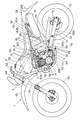
以下、本発明の実施の形態に係る自動2輪車の燃料ポンプ配置構造について、図面を参照しながら説明する。図1は、本発明の実施の形態に係るオフロード用の自動2輪車1を示す左側面図である。なお、以下の説明で使用する方向は、図1を基準とするものであり、車体上下方向を図1の上下方向、車体左右方向を図1の紙面奥行き方向、車体前後方向を図1の紙面左右方向とする。また、図1において、説明を容易にするために、車体外側部を覆うサイドカバーやシュラウドを省略してある。 Hereinafter, a fuel pump arrangement structure of a motorcycle according to an embodiment of the present invention will be described with reference to the drawings. FIG. 1 is a left side view showing an off-road motorcycle 1 according to an embodiment of the present invention. The directions used in the following description are based on FIG. 1. The vertical direction of the vehicle is the vertical direction of FIG. 1, the horizontal direction of the vehicle is the depth direction of FIG. 1, and the longitudinal direction of the vehicle is the plane of FIG. Left and right direction. In FIG. 1, a side cover and a shroud covering the outer side of the vehicle body are omitted for ease of explanation.
自動2輪車1の車体フレーム2は、図1に示すように、ヘッドパイプ3から車体後方斜め下側に延びる1本のメインフレーム10と、メインフレーム10の下側にヘッドパイプ3から車体下方に延びるダウンチューブ20Aと、このダウンチューブ20Aの下側に連なり、車体下方を後方に延びる左右一対のロアーパイプ20B,20Bと、メインフレーム10の後端とロアーパイプ20B,20Bの後端とを連結する左右一対のセンターフレーム30L,30R(左側を30R、右側を30Lとする)とを備えている。この車体フレーム2は、クレードル型フレームを構成しており、この車体フレーム2で囲まれた内方には、エンジンハンガを介してエンジン4が懸架されている。
As shown in FIG. 1, the body frame 2 of the motorcycle 1 includes a
センターフレーム30L,30Rには、車体後方に延出するリアフレーム40,40が取り付けられている。このリアフレーム40は、センターフレーム30L,30Rの下部から車体後方斜め上側に向けて延びる左右一対のパイプ40A,40Aと、センターフレーム30L,30Rの上部から車体後方に延びる左右一対のパイプ40B,40Bとで構成されている。これらのパイプ40Aと40Bとの後端は各々連結されており、これらのパイプ40A、40Bに、シート57、リアフェンダ58及び図示しないサイドカバーが取り付けられるようになっている。
Rear frames 40, 40 extending rearward of the vehicle body are attached to the
ヘッドパイプ3の下側には、前輪60を軸支する左右一対のフロントフォーク61が設けられている。また、ヘッドパイプ3の上側には、操作用ハンドル63が固定されるトップブリッジ64が連結されている。また、ヘッドパイプ3の下側には、前輪60の上方を覆うようにフロントフェンダ65が取り付けられている。
A pair of left and
センターフレーム30は、その下側に湾曲部30Aを有し、この湾曲部30Aには、車体左右方向に貫通するピボット軸32が設けられている。このピボット軸32には、後輪70を軸支するスイングアーム71の前端が上下に揺動自在に支持される。また、後輪70に設けられたスプロケット72と、エンジン4の出力軸5Aに設けられたスプロケット73には、ドライブチェーン74が巻回されており、エンジン4の駆動力は、このドライブチェーン74を介して後輪70に伝達される。
The center frame 30 has a
また、湾曲部30Aの下方には、センターフレーム30L,30Rを左右に連結するクロスメンバ(図示せず)が設けられており、このクロスメンバ79の幅方向の中央部には、フレーム側ブラケット33が取り付けられており、このフレーム側ブラケット33にスタンドが取り付けられている。
A cross member (not shown) for connecting the
スイングアーム71は、ピボット軸32から車両後方向に延在し、後輪70を跨ぐ左右一対のアーム92a、92bによって構成されている。この左右のアーム92a、92bは、後輪の前方の部分でクロスフレーム71a(図2および図4参照)によって連結されている。このクロスフレーム71aの上端には、支持部71bが設けられており、この支持部71bには、リアクッション80の下部が回動自在に取り付けられている。また、リアクッション80の上部は、センターフレーム30の上部に設けられ、クッション支持部に回動自在に取り付けられている。
The
さらに、湾曲部30Aの前方であって、エンジン4の下側部の近傍には、ギヤチェンジペダル34が設けられている。
Further, a
エンジン4は、クランクケース5(変速機)と、クランクケース5の前部から略上方に延出するシリンダブロック6と、シリンダブロック6の上部に連結されるシリンダヘッド7とを備えており、シリンダブロック6内に1つのシリンダを有する単気筒エンジンである。シリンダブロック6には、シリンダ内にピストンが往復移動自在に収容されている。また、クランクケース5には、ピストンにコンロッドを介して連結されたクランク軸や当該エンジンの出力軸5Aが軸支されると共に、このクランク軸と出力軸5Aとの間の動力伝達機構を構成するクラッチ機構や変速機構等が収容されている。
The
また、エンジン4の後方であってセンターフレーム30L,30Rの前側には、スターティングモータ(エンジンの補機、図示せず)が配設されている。
Further, a starting motor (an engine accessory, not shown) is disposed behind the
シリンダヘッド7には、シリンダブロック6内のシリンダに連通する吸排気通路を開閉する吸排気バルブが収容され、この吸排気通路の吸気口7Aがシリンダヘッド7の背面に形成されている。この吸気口7Aには、コーンチューブを介してスロットルボディ8が連結され、このスロットルボディ8には、シート57の下側に位置するエアクリーナボックス9が連結されている。これらのシリンダヘッド7、スロットルボディ8、エアクリーナボックス9は、吸気効率が向上するように略直線状に配置されている。
The
シリンダヘッド7の前面には、吸排気通路の排気口7Bが形成されている。この排気口7Bには、排気管50が接続されている。この排気管50は、排気口7Bから前方へ延びてシリンダヘッド7の右側方へ屈曲し、車両右側を車両後方に延出している(詳細は図2参照)。排気管50の延出端には、排気マフラー51が連結されている。
An
また、シリンダヘッド7の上方であって、シート57の前方には、燃料タンク56が配置されている。この燃料タンク56には、燃料配管59を介して燃料ポンプ81が接続されている。なお、本実施の形態に係る自動2輪車では、燃料タンク56の外部に燃料ポンプ81が配置されている。この燃料ポンプ81の配置についての詳細は後述する。
A
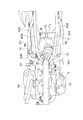
図2は、自動2輪車を上側から見た図であって、燃料ポンプの取付位置を示す概要図である。なお、本図では、説明を容易にするために、エンジン4のシリンダブロック6やシリンダヘッド7、燃料タンク56、リアクッション80、エアクリーナボックス9、スロットルボディ8を省略して記載してある。
FIG. 2 is a diagram of the motorcycle viewed from above, and is a schematic diagram showing the mounting position of the fuel pump. In the drawing, the
図2において、車体幅方向中央部を前後に延びるメインフレーム10の後部からは、左右に分岐する態様で下方に延びる2本のセンターフレーム30L、30Rと、左右に分岐する態様で後方に延びる2本のパイプ40Bが延在している。また、パイプ40Bの下側で左右のセンターフレーム30L、30Rから後方に延びるパイプ40Aが延在している。また、センターフレーム30L、30Rを連結する態様のピボット軸32から車体後方にスイングアーム71が延在している。
In FIG. 2, from the rear part of the
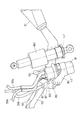
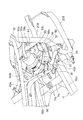
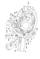
図3は、燃料ポンプ81、リアクッション80および排気管50の位置関係を示す斜視図である。なお、図3において、紙面左側が車両前方となる。また、図4は、燃料ポンプ81とスイングアーム71との位置関係車両の斜め後ろ側から見た斜視図である。なお、図4において、紙面右斜め上側が車両前方となる。
燃料ポンプ81は、略円筒形状の外形を有しており、燃料タンク56に接続される2本の燃料パイプ59aと、スロットルボディ8に接続される燃料パイプ59bとが配管されている。
3 is a perspective view showing the positional relationship between the
The
燃料ポンプ81の車両前後方向の位置は、図2に示すように、クランクケース5よりも後側であって、リアクッション80よりも前側に位置するように配置されている。より詳細には、燃料ポンプ81は、ピボット軸32の後側であって、スイングアーム71のクロスフレーム71aの前側に配置されている。この燃料ポンプ81の軸線L2は、図3に示すように、リアクッション80の軸線L1とほぼ平行に配置されており、スペースの無駄が生じないようにしている。
As shown in FIG. 2, the position of the
また、燃料ポンプ81の車両幅方向の位置は、図2に示すように、左右のセンターフレーム30L、30Rの間に配置されている。より詳細には、燃料ポンプ81は、スイングアーム71の左右のアーム92a、92bの間に配置されている。
Further, the position of the
さらに、燃料ポンプ81の車両高さ方向の位置は、図3に示すように、リアクッション80の下側部分とほぼ同じ高さの位置に配置されている。
Further, the position of the
すなわち、燃料ポンプ81は、リアクッション80下部の取付部をスイングアーム71のクロスフレーム71aに取り付けることによって形成されたリアクッション80の前側のスペースに配置されている。これにより、スペースの有効活用が図られている。
That is, the
一方、車体右側部には、上述の通り排気管50が引き回されており(図2参照)、この排気管50の途中には、触媒を設ける必要がある。この触媒の大きさ、体積は、近年の排ガス規制によって、従来に比べて大きくする必要がある。本実施の形態では、図2に示すように、排気管50の車体前後方向に延びる中間部であって、前後方向においてピボット軸32からクロスフレーム71aの後端までの間に触媒90が設けられている。
On the other hand, the
燃料ポンプ81をこのような位置に配置すると、上述した触媒90と燃料ポンプ81との間の距離が短くなり、燃料ポンプ81への熱の影響が懸念される。そのため、この触媒90には、略円筒形状の外周を覆うように、第1遮熱カバー91が設けられている(図2参照)。
なお、触媒90の前側の排気管50には、この排気管50が車両外側に表出するのを防ぐためのカバー部材93が設けられている。
When the
The
また、燃料ポンプ81の外周面には、図4に示すように、その周方向に亘って燃料ポンプ支持部材96が取り付けられている。一方、左右のセンターフレーム30L、30Rを連結するクロスメンバ94には、ハンガーブラケット95が取り付けられている。
燃料ポンプ支持部材96の右側部分(触媒90が延在する部分)には、前方斜め外側に向かって延びる態様でブラケット97が取り付けられており、このブラケット97の前側先端からハンガーブラケット95までの間を第2遮熱カバー98によって支持されている。この第2遮熱カバー98は、ブラケット97の前側先端とボルト82で固定されており、ハンガーブラケット95と溶接によって固定されている。また、燃料ポンプ支持部材96の左側部分(図3参照)には、燃料ポンプ支持部材96を車体に取り付けるためのポンプブラケット85が取り付けられ、このポンプブラケット85は左右のセンターフレーム30L、30Rを連結するクロスメンバ94に設けられたフランジ部86(図5参照)にボルト87(図3参照)によって取り付けられている。また、このポンプブラケット85は、エンジンハンガーとしての機能を備えている。詳細には、図3に示すように、車体前方下側に取付穴88を有し、この取付穴88を用いてエンジン4を懸架する。すなわち、ハンガーブラケット95とポンプブラケット85でエンジン4を懸架している。
Further, as shown in FIG. 4, a fuel
A
第2遮熱カバー98は、上述の通り、燃料ポンプ81を支持する強度部材としての機能を果たすとともに、触媒90からの熱を燃料ポンプ81に伝わりにくくする機能も果たしている。そのため、第2遮熱カバー98は、図4に示すように、ブラケット97の高さ方向の長さと比較して上側に長く形成されており、燃料ポンプ81へ伝わる熱を、より大きな面積で遮熱できるようにしている。
As described above, the second heat shield cover 98 functions as a strength member that supports the
図5は、第2遮熱カバー98の取付位置を車両の斜め前側から見た外観斜視図である。
排気管50(図5では、センターフレーム30より前側を省略してある)は、車体右側のセンターフレーム30Rよりも車体内方側を引き回されている(図2参照)。第2遮熱カバー98は、この排気管50と燃料ポンプ81(図5では省略)との間に配置されている。この第2遮熱カバー98の外面98aは、車両外側、すなわち、排気管50或いは触媒90の方向に向けられている。
FIG. 5 is an external perspective view of the mounting position of the second
The exhaust pipe 50 (the front side of the center frame 30 is omitted in FIG. 5) is routed inward of the vehicle body from the
また、燃料ポンプ81は、横方向に突出して燃料パイプ59bが取り付けられるジョイント(図示せず)と、上方向に突出し、2本の燃料パイプ59aが取り付けられるジョイント(図示せず)とを備えている。これにより、燃料ポンプ81内に貯留されている燃料は、燃料パイプ59bを介してスロットルボディ8へと送られることになる。また、燃料タンク56内の燃料は、燃料パイプ59aを介して、燃料ポンプ81内に送られることになる。この燃料ポンプ81は、燃料の補助タンクとしての機能をも果たすものである。
The
本発明の実施の形態に係る自動2輪車の燃料ポンプ配置構造によれば、燃料ポンプ81をエンジン4のクランクケース5の後端部とリアクッション80との間であって、ピボット軸32と、クロスフレーム71aとの間に配置しているので、リアクッション80の下端をクロスフレーム71aの支持部71bに支持させることによってできたリアクッション80の前側の空きスペースに燃料ポンプ81を配置し、エンジン4の後方であってエンジン4の熱対策が必要のないスペースを有効に活用することができる。また、スペースを有効活用できるので、設計レイアウトの自由度が高い。さらに、燃料ポンプ81を車体下方に配置することができるので、低重心化を実現することができる。
According to the fuel pump arrangement structure of the motorcycle according to the embodiment of the present invention, the
また、燃料ポンプ81を左右のセンターフレーム30L、30R間であって、スイングアーム71の左右のアーム92a間に燃料ポンプ81を配置しているので、左右のセンターフレーム30L、30Rおよびクロスフレーム71aで囲われるようになり、燃料ポンプ81を外部から保護することができる。また、スペースを有効活用できるとともに、燃料ポンプ81を車体の低い位置に配置することで、低重心化を実現することができる。
Further, since the
さらに、車体前後方向に延出する排気管50の中間部に触媒90を設け、この触媒90の側方に燃料ポンプ81を配置し、燃料ポンプ81と触媒90或いは排気管50との間に第1遮熱カバー91および第2遮熱カバー98を設けているので、触媒90或いは排気管50からの熱影響を受けにくくすることができる。また、触媒90と燃料ポンプ81とを近傍のスペース内で共存させることで、スペースを有効活用することができる。さらに、排ガス規制によって体積が大きくなった触媒90を車体下方に配置することで、低重心化を実現することができる。
Further, a
また、前記触媒の一部を第1遮熱カバーで覆い、触媒90或いは排気管50と燃料ポンプ81との間に第2遮熱カバー98を介在させて、この第2遮熱カバー98で燃料ポンプ81を支持しているので、第2遮熱カバー98に燃料ポンプ81の支持部材と遮熱カバーとの2つの機能を持たせることで、スペースを有効活用することができる。
A part of the catalyst is covered with a first heat shield cover, and a second
また、燃料ポンプ81を車体側に取り付ける支持部材が、第2遮熱カバー98として構成されているので、この第2遮熱カバー98で燃料ポンプ81を支持することができ、支持部材を設ける必要がない。そのため、部品点数を削減することができる。
Further, since the support member for attaching the
さらに、リアクッション80の軸線と燃料ポンプ81の軸線とをほぼ平行に配置しているので、外観性も良く最適な設計レイアウトを実現することができる。
Furthermore, since the axis of the
以上、本発明の実施の形態について述べたが、本発明の技術思想に基づいて各種の変形および変更が可能である。
例えば、本実施の形態では、燃料ポンプ81と触媒90或いは排気管50との間に2つの遮熱カバーを設けているが、熱の伝達を確実に防止することができるものであれば1つの遮熱カバーで構成してもよい。これにより、触媒90から伝わる熱を遮熱カバーで遮蔽し、燃料ポンプ81に熱影響を及ぼさないようにすることができる。また、燃料ポンプ81と触媒90とを、車体下方であってほぼ同じ高さに配置することで、低重心化を実現することができる。
While the embodiments of the present invention have been described above, various modifications and changes can be made based on the technical idea of the present invention.
For example, in the present embodiment, two heat shield covers are provided between the
1 自動2輪車
2 車体フレーム
3 ヘッドパイプ
4 エンジン
5 クランクケース(変速機)
7B 排気口
10 メインフレーム
20A ダウンチューブ
20B ロアーパイプ
30 センターフレーム
30A 湾曲部
32 ピボット軸
40 リアフレーム
40A、40B パイプ
50 排気管
51 排気マフラー
56 燃料タンク
59 燃料配管
60 前輪
70 後輪
71 スイングアーム
71a クロスフレーム
71b 支持部
80 リアクッション
81 燃料ポンプ
82 ボルト
90 触媒
91 第1遮熱カバー
92a アーム
93 カバー部材
94 クロスメンバ
95 ハンガーブラケット
96 燃料ポンプ支持部材
97 ブラケット
98 第2遮熱カバー
98a 外面
L1、L2 軸線
1 Motorcycle 2
Claims (8)
前記燃料ポンプを前記エンジンの変速機と前記クッションとの間に配置したことを特徴とする自動2輪車の燃料ポンプ配置構造。 A main frame that supports vehicle body components such as an engine and a fuel tank, a pair of left and right center frames extending up and down behind the engine, and a pair of left and right swingable about a pivot shaft provided on the center frame A fuel pump arrangement structure for a motorcycle comprising a swing arm and a cushion having a lower end supported by a cross frame connecting the left and right swing arms, and a fuel pump arranged outside the fuel tank,
A fuel pump arrangement structure for a motorcycle, wherein the fuel pump is arranged between a transmission of the engine and the cushion.
Priority Applications (2)
| Application Number | Priority Date | Filing Date | Title |
|---|---|---|---|
| JP2008049379A JP5295590B2 (en) | 2008-02-29 | 2008-02-29 | Motorcycle fuel pump arrangement structure |
| BRPI0900625A BRPI0900625B8 (en) | 2008-02-29 | 2009-02-18 | MOTORCYCLE FUEL PUMP LAYOUT STRUCTURE |
Applications Claiming Priority (1)
| Application Number | Priority Date | Filing Date | Title |
|---|---|---|---|
| JP2008049379A JP5295590B2 (en) | 2008-02-29 | 2008-02-29 | Motorcycle fuel pump arrangement structure |
Publications (3)
| Publication Number | Publication Date |
|---|---|
| JP2009202808A true JP2009202808A (en) | 2009-09-10 |
| JP2009202808A5 JP2009202808A5 (en) | 2011-03-10 |
| JP5295590B2 JP5295590B2 (en) | 2013-09-18 |
Family
ID=41145492
Family Applications (1)
| Application Number | Title | Priority Date | Filing Date |
|---|---|---|---|
| JP2008049379A Expired - Fee Related JP5295590B2 (en) | 2008-02-29 | 2008-02-29 | Motorcycle fuel pump arrangement structure |
Country Status (2)
| Country | Link |
|---|---|
| JP (1) | JP5295590B2 (en) |
| BR (1) | BRPI0900625B8 (en) |
Cited By (4)
| Publication number | Priority date | Publication date | Assignee | Title |
|---|---|---|---|---|
| US20110073079A1 (en) * | 2009-09-29 | 2011-03-31 | Ishii Tsubasa | Fuel supply system for motorcycle |
| JP2011074767A (en) * | 2009-09-29 | 2011-04-14 | Honda Motor Co Ltd | Fuel supply device for motorcycle |
| JP2012076646A (en) * | 2010-10-04 | 2012-04-19 | Kawasaki Heavy Ind Ltd | Fuel hose |
| CN104627294A (en) * | 2013-11-15 | 2015-05-20 | 雅马哈发动机株式会社 | Electric motorcycle |
Citations (6)
| Publication number | Priority date | Publication date | Assignee | Title |
|---|---|---|---|---|
| JPS5964323U (en) * | 1982-10-25 | 1984-04-27 | スズキ株式会社 | Motorcycle fuel supply system |
| JP2004284473A (en) * | 2003-03-20 | 2004-10-14 | Honda Motor Co Ltd | Motorcycle fuel pump arrangement |
| JP2004284395A (en) * | 2003-03-19 | 2004-10-14 | Honda Motor Co Ltd | Motorcycle |
| JP2006001308A (en) * | 2004-06-15 | 2006-01-05 | Honda Motor Co Ltd | Fuel return structure of vehicle fuel pump |
| JP2007023802A (en) * | 2005-07-12 | 2007-02-01 | Yamaha Motor Co Ltd | Saddle riding type vehicle |
| JP2007153005A (en) * | 2005-12-01 | 2007-06-21 | Honda Motor Co Ltd | Motorcycle |
-
2008
- 2008-02-29 JP JP2008049379A patent/JP5295590B2/en not_active Expired - Fee Related
-
2009
- 2009-02-18 BR BRPI0900625A patent/BRPI0900625B8/en active IP Right Grant
Patent Citations (6)
| Publication number | Priority date | Publication date | Assignee | Title |
|---|---|---|---|---|
| JPS5964323U (en) * | 1982-10-25 | 1984-04-27 | スズキ株式会社 | Motorcycle fuel supply system |
| JP2004284395A (en) * | 2003-03-19 | 2004-10-14 | Honda Motor Co Ltd | Motorcycle |
| JP2004284473A (en) * | 2003-03-20 | 2004-10-14 | Honda Motor Co Ltd | Motorcycle fuel pump arrangement |
| JP2006001308A (en) * | 2004-06-15 | 2006-01-05 | Honda Motor Co Ltd | Fuel return structure of vehicle fuel pump |
| JP2007023802A (en) * | 2005-07-12 | 2007-02-01 | Yamaha Motor Co Ltd | Saddle riding type vehicle |
| JP2007153005A (en) * | 2005-12-01 | 2007-06-21 | Honda Motor Co Ltd | Motorcycle |
Cited By (8)
| Publication number | Priority date | Publication date | Assignee | Title |
|---|---|---|---|---|
| US20110073079A1 (en) * | 2009-09-29 | 2011-03-31 | Ishii Tsubasa | Fuel supply system for motorcycle |
| JP2011074767A (en) * | 2009-09-29 | 2011-04-14 | Honda Motor Co Ltd | Fuel supply device for motorcycle |
| JP2011073479A (en) * | 2009-09-29 | 2011-04-14 | Honda Motor Co Ltd | Fuel supply device of motorcycle |
| US8459236B2 (en) * | 2009-09-29 | 2013-06-11 | Honda Motor Co., Ltd. | Fuel supply system for motorcycle |
| EP2301830A3 (en) * | 2009-09-29 | 2014-08-20 | Honda Motor Co., Ltd. | Fuel supply system for motorcycle |
| JP2012076646A (en) * | 2010-10-04 | 2012-04-19 | Kawasaki Heavy Ind Ltd | Fuel hose |
| CN104627294A (en) * | 2013-11-15 | 2015-05-20 | 雅马哈发动机株式会社 | Electric motorcycle |
| CN104627294B (en) * | 2013-11-15 | 2017-04-12 | 雅马哈发动机株式会社 | Electric motorcycle |
Also Published As
| Publication number | Publication date |
|---|---|
| BRPI0900625B1 (en) | 2020-10-27 |
| JP5295590B2 (en) | 2013-09-18 |
| BRPI0900625A2 (en) | 2009-12-01 |
| BRPI0900625B8 (en) | 2022-07-19 |
Similar Documents
| Publication | Publication Date | Title |
|---|---|---|
| JP5142556B2 (en) | Motorcycle fuel pump arrangement structure | |
| JP2008222078A (en) | Motorcycle | |
| JP5323533B2 (en) | Saddle riding | |
| JP2015074352A (en) | Vehicle body frame and saddle-riding type vehicle including the same | |
| JP5295590B2 (en) | Motorcycle fuel pump arrangement structure | |
| US8622168B2 (en) | Motorcycle exhaust system structure including a resonator provided to an exhaust pipe | |
| CN101463749B (en) | motorcycle exhaust | |
| JP2009162096A (en) | Motorcycle | |
| EP1775208B1 (en) | Straddle-type vehicle | |
| JP2007030688A (en) | Rear cushion arrangement structure for motorcycles | |
| EP2289786A2 (en) | Motorcycle | |
| JP5742505B2 (en) | Motorcycle frame, motorcycle | |
| JP5295688B2 (en) | Motorcycle | |
| US9815521B2 (en) | Exhaust system of saddle-ride type vehicle | |
| JP5966819B2 (en) | Motorcycle | |
| WO2006003759A1 (en) | Two-wheeled motor vehicle | |
| CN101181919B (en) | automatic two-wheeler | |
| JP2005036774A (en) | Motorcycle exhaust system | |
| JP5946355B2 (en) | Saddle riding vehicle | |
| KR100822488B1 (en) | Swing arm suspension | |
| JP4391405B2 (en) | Motorcycle | |
| JP2013136978A (en) | Fuel supply device | |
| CN108626019A (en) | Vehicle structure for installing air-cooled type internal combustion engine | |
| JP4286758B2 (en) | Motorcycle | |
| JP2013193500A (en) | Rear cushion holding structure and saddle-type vehicle |
Legal Events
| Date | Code | Title | Description |
|---|---|---|---|
| A521 | Request for written amendment filed |
Free format text: JAPANESE INTERMEDIATE CODE: A523 Effective date: 20110124 |
|
| A621 | Written request for application examination |
Free format text: JAPANESE INTERMEDIATE CODE: A621 Effective date: 20110124 |
|
| RD02 | Notification of acceptance of power of attorney |
Free format text: JAPANESE INTERMEDIATE CODE: A7422 Effective date: 20110124 |
|
| A977 | Report on retrieval |
Free format text: JAPANESE INTERMEDIATE CODE: A971007 Effective date: 20120726 |
|
| A131 | Notification of reasons for refusal |
Free format text: JAPANESE INTERMEDIATE CODE: A131 Effective date: 20120918 |
|
| A521 | Request for written amendment filed |
Free format text: JAPANESE INTERMEDIATE CODE: A523 Effective date: 20121116 |
|
| TRDD | Decision of grant or rejection written | ||
| A01 | Written decision to grant a patent or to grant a registration (utility model) |
Free format text: JAPANESE INTERMEDIATE CODE: A01 Effective date: 20130604 |
|
| A61 | First payment of annual fees (during grant procedure) |
Free format text: JAPANESE INTERMEDIATE CODE: A61 Effective date: 20130612 |
|
| R150 | Certificate of patent or registration of utility model |
Free format text: JAPANESE INTERMEDIATE CODE: R150 Ref document number: 5295590 Country of ref document: JP Free format text: JAPANESE INTERMEDIATE CODE: R150 |
|
| LAPS | Cancellation because of no payment of annual fees |