JP2009148183A - Harvester - Google Patents

Harvester Download PDF

Info

Publication number
JP2009148183A
JP2009148183A JP2007327692A JP2007327692A JP2009148183A JP 2009148183 A JP2009148183 A JP 2009148183A JP 2007327692 A JP2007327692 A JP 2007327692A JP 2007327692 A JP2007327692 A JP 2007327692A JP 2009148183 A JP2009148183 A JP 2009148183A
Authority
JP
Japan
Prior art keywords
speed
output
constant
traveling
clutch mechanism
Prior art date
Legal status (The legal status is an assumption and is not a legal conclusion. Google has not performed a legal analysis and makes no representation as to the accuracy of the status listed.)
Granted
Application number
JP2007327692A
Other languages
Japanese (ja)
Other versions
JP5057575B2 (en
Inventor
Koichi Kajiwara
康一 梶原
Current Assignee (The listed assignees may be inaccurate. Google has not performed a legal analysis and makes no representation or warranty as to the accuracy of the list.)
Yanmar Co Ltd
Original Assignee
Yanmar Co Ltd
Priority date (The priority date is an assumption and is not a legal conclusion. Google has not performed a legal analysis and makes no representation as to the accuracy of the date listed.)
Filing date
Publication date
Application filed by Yanmar Co Ltd filed Critical Yanmar Co Ltd
Priority to JP2007327692A priority Critical patent/JP5057575B2/en
Publication of JP2009148183A publication Critical patent/JP2009148183A/en
Application granted granted Critical
Publication of JP5057575B2 publication Critical patent/JP5057575B2/en
Expired - Fee Related legal-status Critical Current
Anticipated expiration legal-status Critical

Links

Images

Abstract

<P>PROBLEM TO BE SOLVED: To provide a harvester capable of compactly arranging at a low cost therein a PTO clutch mechanism functioning to drive a farm-working section at a vehicle speed-synchronous speed and a constant-rotating clutch mechanism functioning to drive the farm-working section at a constant rotating speed. <P>SOLUTION: The harvester has the following construction: a transmission case 26 is arranged with a first variable-speed means 88 for putting engine output to speed variation, a second variable-speed means 89 for putting the output of the first variable-speed means 88, and a third variable-speed means 102 for putting the output of the second variable-speed means 89 so as to transmit the output of an engine 20 via the PTO shaft 94 on the output side of the second variable-speed means 89 to a farm-working section. The inside of the transmission case 26 is installed with a PTO clutch mechanism 110 functioning to drive the farm-working section at a vehicle speed-synchronous speed, and a constant-rotating clutch mechanism 111 functioning to drive the farm-working section at a constant rotating speed, wherein the PTO clutch mechanism 110 is arranged in between the output side of the second variable-speed means 89 and the PTO shaft 94, and the constant-rotating clutch mechanism 111 is arranged in between the input side of the first variable-speed means 88 and the PTO shaft 94. <P>COPYRIGHT: (C)2009,JPO&INPIT

Description

本発明は、圃場に植立した穀稈を刈取って穀粒を収集する農作業部を設けたコンバイン、又は飼料用穀稈や牧草等を刈取って飼料として収集する農作業部を設けた飼料収穫機、又は圃場のキャベツや大根やたまねぎ等の野菜を取込む農作業部を設けた野菜収穫機等の収穫機に係り、より詳しくは、走行部又は農作業部にエンジンの出力を伝達するミッションケースを備え、走行部と農作業部とを同調して作動するようにした収穫機に関するものである。   The present invention relates to a combine harvester provided with a farming unit that harvests grains by harvesting cereals planted in a field, or a feed harvester provided with a farming unit that harvests cereals and pasture for feed and collects them as feed Or a harvester such as a vegetable harvester equipped with a farming unit that takes in vegetables such as cabbage, radish and onion in the field, and more specifically, a transmission case that transmits engine output to the traveling unit or farming unit. It is related with the harvester which prepared and was made to operate | move in synchronization with a traveling part and an agricultural work part.

従来、一般的に、農作業部を設けた収穫機は、エンジンの出力が最高になる状態にエンジンの出力回転数を維持し、ミッションケースから走行部と農作業部とにエンジンの出力を伝達し、車速と同調した速度で農作業部を作動することによって、車速が変更されても、圃場の作物に対して農作業部が略一定の速度で作用するように構成している。   Conventionally, in general, a harvesting machine provided with a farming unit maintains the engine output speed in a state where the engine output is maximized, and transmits the engine output from the mission case to the traveling unit and the farming unit, By operating the farm working unit at a speed synchronized with the vehicle speed, the farm working unit operates at a substantially constant speed on crops in the field even when the vehicle speed is changed.

従来のコンバインにおいては、特許文献1に示されるように、ミッションケースに、エンジンの出力を変速する走行用油圧ポンプ(第1変速手段)と、走行用油圧ポンプの出力をさらに変速する走行用油圧モータ(第2変速手段)と、走行用油圧モータの出力をさらに変速する副変速機構(第3変速手段)とを配置している。また、走行用油圧モータの出力側に刈取駆動プーリ(PTO軸)を連結して、走行用油圧モータから刈取駆動プーリを介して刈取装置(農作業部)にエンジンの出力を伝達するように構成している。(例えば、特許文献1参照)。
特開2005−261279号公報
In the conventional combine, as shown in Patent Document 1, a traveling hydraulic pump (first transmission means) for shifting the output of the engine and a traveling hydraulic pressure for further shifting the output of the traveling hydraulic pump are provided in the transmission case. A motor (second transmission means) and an auxiliary transmission mechanism (third transmission means) for further changing the output of the traveling hydraulic motor are arranged. Further, a cutting drive pulley (PTO shaft) is connected to the output side of the traveling hydraulic motor, and the engine output is transmitted from the traveling hydraulic motor to the cutting device (farm working unit) via the cutting drive pulley. ing. (For example, refer to Patent Document 1).
JP 2005-261279 A

前記従来技術は、特許文献1に示されるように、走行機体の前部に、エンジンから刈取装置への動力伝達用のカウンタケースを取付けている。このカウンタケースに、低速側車速同調出力又は高速側車速同調出力に切換えるための車速同調用の刈取変速機構(PTOクラッチ機構)と、低速側一定回転作動状態又は高速側一定回転作動状態に切換えるための刈取定速機構(一定回転クラッチ機構)とを内蔵している。刈取変速機構に、エンジンからの動力を、ミッションケースにおける車速変速機構から入力する一方、刈取定速機構に、エンジンからの一定回転動力を直接に入力するという構成にしている。   In the prior art, as shown in Patent Document 1, a counter case for transmitting power from the engine to the cutting device is attached to the front portion of the traveling machine body. To this counter case, a cutting speed change mechanism (PTO clutch mechanism) for tuning the vehicle speed for switching to the low speed side vehicle speed synchronized output or the high speed side vehicle speed synchronized output, and the low speed side constant rotational operation state or the high speed side constant rotational operation state. And a constant cutting mechanism (constant rotation clutch mechanism). The power from the engine is input to the mowing transmission mechanism from the vehicle speed transmission mechanism in the transmission case, while the constant rotational power from the engine is directly input to the mowing constant speed mechanism.

したがって、特許文献1では、車速同調用の刈取変速機構と刈取定速機構とを、テンションクラッチを有するベルト伝動機構によって構成する駆動構造に比べて、エンジンとミッションケース、及びエンジンと刈取装置との間にそれぞれ配置するベルト伝動機構を簡単に構成できる。しかし、走行機体の前部に設けたカウンタケースが、これに車速同調用の刈取変速機構と刈取定速機構とを内蔵することで、コンバインにおける走行機体の大型化及び重量及び製造コストのアップを招来するという問題がある。また、走行機体には脱穀装置が搭載されており、脱穀装置の前面に存在する前記大型のカウンタケースが、脱穀装置に対するメンテナンス性を妨げることになるという問題もある。   Therefore, in patent document 1, compared with the drive structure which comprises the cutting transmission speed-change mechanism and cutting constant speed mechanism for vehicle speed synchronization by the belt transmission mechanism which has a tension clutch, an engine, a transmission case, and an engine and a cutting device are included. The belt transmission mechanism disposed between each can be easily configured. However, the counter case provided at the front of the traveling machine body incorporates a cutting speed change mechanism and a constant cutting speed mechanism for synchronizing the vehicle speed, thereby increasing the size of the traveling machine body in the combine and increasing the weight and manufacturing cost. There is a problem of being invited. In addition, a threshing device is mounted on the traveling machine body, and there is a problem that the large counter case present on the front surface of the threshing device hinders maintainability of the threshing device.

本発明の目的は、第1変速手段と第2変速手段と第3変速手段とを有するミッションケースを利用して、車速同調速度で農作業部を駆動するPTOクラッチ機構と、一定回転速度で農作業部を駆動する一定回転クラッチ機構とを、コンパクトに且つ低コストに配置できるようにした収穫機を提供するものである。   An object of the present invention is to provide a PTO clutch mechanism for driving a farm working unit at a vehicle speed synchronization speed using a transmission case having a first transmission unit, a second transmission unit, and a third transmission unit, and a farm working unit at a constant rotational speed. And a constant rotation clutch mechanism that drives the harvesting machine can be provided in a compact and low-cost manner.

前記目的を達成するため、請求項1に係る発明の収穫機は、エンジンによって作動する走行部を備えた走行機体と、前記走行機体に配置する農作業部と、前記走行部又は前記農作業部に前記エンジンの出力を伝達するミッションケースとを備え、前記ミッションケースに、前記エンジンの出力を変速する第1変速手段と、第1変速手段の出力を変速する第2変速手段と、第2変速手段の出力を変速する第3変速手段とを配置し、前記第2変速手段の出力側にPTO軸を連結して、前記第2変速手段から前記PTO軸を介して前記農作業部に前記エンジンの出力を伝達するように構成してなる収穫機において、前記ミッションケースの内部に、車速同調速度で前記農作業部を駆動するPTOクラッチ機構と、一定回転速度で前記農作業部を駆動する一定回転クラッチ機構とを設け、前記第2変速手段の出力側と前記PTO軸との間に前記PTOクラッチ機構を配置し、前記第1変速手段の入力側と前記PTO軸との間に前記一定回転クラッチ機構を配置したものである。   In order to achieve the object, the harvesting machine of the invention according to claim 1 includes a traveling machine body having a traveling unit that is operated by an engine, an agricultural work unit disposed in the traveling machine body, and the traveling unit or the agricultural working unit. A transmission case for transmitting the output of the engine; a first transmission means for shifting the output of the engine; a second transmission means for shifting the output of the first transmission means; and a second transmission means. A third speed change means for shifting the output, a PTO shaft is connected to the output side of the second speed change means, and the output of the engine is transmitted from the second speed change means to the farm working section via the PTO shaft. In the harvesting machine configured to transmit, a PTO clutch mechanism that drives the farm working unit at a vehicle speed synchronization speed and the farm working unit driven at a constant rotational speed inside the mission case. A constant rotation clutch mechanism, wherein the PTO clutch mechanism is disposed between the output side of the second transmission means and the PTO shaft, and the input side of the first transmission means and the PTO shaft are A constant rotation clutch mechanism is arranged.

請求項2に記載の発明は、請求項1に記載の収穫機において、前記PTOクラッチ機構又は前記一定回転クラッチ機構からのいずれか一方の高速側出力を、前記PTO軸に伝達するクラッチ手段を備えたものである。   A second aspect of the present invention is the harvester according to the first aspect, further comprising clutch means for transmitting the high-speed side output from the PTO clutch mechanism or the constant rotation clutch mechanism to the PTO shaft. It is a thing.

請求項3に記載の発明は、請求項1に記載の収穫機において、前記ミッションケースと異なる前記農作業部用の駆動経路を形成し、その駆動経路中に定速回転機構を設け、前記農作業部に前記定速回転機構を介して前記エンジンの回転力を伝達するように構成し、また前記PTOクラッチ機構から前記PTO軸を介して前記農作業部に伝達する車速同調回転数よりも高い回転数の高速回転出力によって、前記一定回転クラッチ機構を介して前記農作業部を作動可能に構成した構造であって、前記走行機体の移動速度が一定以下のときに、前記一定回転クラッチ機構から前記PTO軸を介して前記農作業部に伝達する回転数よりも低い回転数の低速回転出力によって、前記定速回転機構を介して前記農作業部が作動するように構成し、前記走行機体の移動速度が一定以上のときに、前記定速回転機構を介して前記農作業部を作動する操作が実行されても、前記一定回転クラッチ機構からの高速回転出力によって前記農作業部が作動するように構成したものである。   According to a third aspect of the present invention, in the harvesting machine according to the first aspect, a drive path for the farm work unit different from the mission case is formed, a constant speed rotation mechanism is provided in the drive path, and the farm work unit The rotational speed of the engine is transmitted through the constant speed rotational mechanism, and the rotational speed of the vehicle is higher than the vehicle speed synchronized rotational speed transmitted from the PTO clutch mechanism to the farm working unit through the PTO shaft. The structure is such that the farm working unit can be operated via the constant rotation clutch mechanism by high-speed rotation output, and the PTO shaft is moved from the constant rotation clutch mechanism when the traveling speed of the traveling aircraft is below a certain level. The farm working unit is configured to operate via the constant-speed rotation mechanism by a low-speed rotational output having a rotational speed lower than the rotational speed transmitted to the farm working unit via the traveling Even when an operation for operating the farm work unit is performed via the constant speed rotation mechanism when the moving speed of the body is above a certain level, the farm work unit is operated by a high-speed rotation output from the constant rotation clutch mechanism. It is configured.

請求項1に係る発明によれば、エンジンによって作動する走行部を備えた走行機体と、前記走行機体に配置する農作業部と、前記走行部又は前記農作業部に前記エンジンの出力を伝達するミッションケースとを備え、前記ミッションケースに、前記エンジンの出力を変速する第1変速手段と、第1変速手段の出力を変速する第2変速手段と、第2変速手段の出力を変速する第3変速手段とを配置し、前記第2変速手段の出力側にPTO軸を連結して、前記第2変速手段から前記PTO軸を介して前記農作業部に前記エンジンの出力を伝達するように構成してなる収穫機において、前記ミッションケースの内部に、車速同調速度で前記農作業部を駆動するPTOクラッチ機構と、一定回転速度で前記農作業部を駆動する一定回転クラッチ機構とを設け、前記第2変速手段の出力側と前記PTO軸との間に前記PTOクラッチ機構を配置し、前記第1変速手段の入力側と前記PTO軸との間に前記一定回転クラッチ機構を配置している。   According to the first aspect of the present invention, a traveling machine body including a traveling unit that is operated by an engine, an agricultural work unit disposed on the traveling machine body, and a transmission case that transmits the output of the engine to the traveling unit or the agricultural work unit. First transmission means for changing the output of the engine, second transmission means for changing the output of the first transmission means, and third transmission means for changing the output of the second transmission means. And a PTO shaft is connected to the output side of the second transmission means, and the output of the engine is transmitted from the second transmission means to the farm working unit via the PTO shaft. In the harvesting machine, a PTO clutch mechanism that drives the farm working unit at a vehicle speed synchronization speed, and a constant rotation clutch mechanism that drives the farm working unit at a constant rotational speed are provided inside the mission case. The PTO clutch mechanism is disposed between the output side of the second transmission means and the PTO shaft, and the constant rotation clutch mechanism is disposed between the input side of the first transmission means and the PTO shaft. ing.

したがって、請求項1に係る発明によれば、前記PTOクラッチ機構と前記一定回転クラッチ機構とを、テンションクラッチを有するベルト伝動機構を利用して構成する従来の駆動構造に比べて、前記エンジンと前記ミッションケース、及び前記エンジンと前記農作業部との間にそれぞれ配置するベルト伝動機構を簡単に構成できる。そのベルト伝動機構のメンテナンス作業性等を向上できる。また、前記第1変速手段と前記第2変速手段と前記第3変速手段とを有する前記ミッションケースを利用して、前記PTOクラッチ機構と、前記一定回転クラッチ機構とを、コンパクトに且つ低コストに配置できる。また、前記ミッションケースに、前記PTOクラッチ機構と前記一定回転クラッチ機構とを内蔵したことにより、従来のように前記走行機体の前部にカウンタケースを設けることを省略できるか、或いは、仮りに前記カウンタケースを設けるにしても、このカウンタケースを小型化できるものである。   Therefore, according to the invention according to claim 1, the engine and the constant rotation clutch mechanism are compared with the conventional drive structure in which the belt transmission mechanism having a tension clutch is used to configure the PTO clutch mechanism and the constant rotation clutch mechanism. The transmission case and the belt transmission mechanism disposed between the engine and the farm working unit can be easily configured. The maintenance workability of the belt transmission mechanism can be improved. Further, the PTO clutch mechanism and the constant rotation clutch mechanism can be made compact and low-cost by using the transmission case having the first transmission unit, the second transmission unit, and the third transmission unit. Can be placed. Further, since the PTO clutch mechanism and the constant rotation clutch mechanism are built in the transmission case, it is possible to omit providing a counter case at the front of the traveling machine body as in the prior art, or temporarily Even if a counter case is provided, the counter case can be reduced in size.

請求項2に係る発明によれば、前記PTOクラッチ機構又は前記一定回転クラッチ機構からのいずれか一方の高速側出力を、前記PTO軸に伝達するクラッチ手段を備えたものであるから、前記PTOクラッチ機構の車速同調用の変速出力、又は前記一定回転クラッチ機構の一定回転出力の両方が前記農作業部に同時に伝達されるのを防止できる。また、前記走行機体の後進によって前記PTO軸が逆転するのを防止できるものである。   According to the second aspect of the invention, since the PTO clutch mechanism or the constant rotation clutch mechanism is provided with clutch means for transmitting the high-speed side output from the PTO shaft to the PTO shaft, the PTO clutch It is possible to prevent both the shift output for synchronizing the vehicle speed of the mechanism and the constant rotation output of the constant rotation clutch mechanism from being simultaneously transmitted to the farm working unit. Further, it is possible to prevent the PTO shaft from reversing due to the reverse travel of the traveling machine body.

請求項3に係る発明によれば、前記ミッションケースと異なる前記農作業部用の駆動経路を形成し、その駆動経路中に定速回転機構を設け、前記農作業部に前記定速回転機構を介して前記エンジンの回転力を伝達するように構成し、また前記PTOクラッチ機構から前記PTO軸を介して前記農作業部に伝達する車速同調回転数よりも高い回転数の高速回転出力によって、前記一定回転クラッチ機構を介して前記農作業部を作動可能に構成した構造であって、前記走行機体の移動速度が一定以下のときに、前記一定回転クラッチ機構から前記PTO軸を介して前記農作業部に伝達する回転数よりも低い回転数の低速回転出力によって、前記定速回転機構を介して前記農作業部が作動するように構成し、前記走行機体の移動速度が一定以上のときに、前記定速回転機構を介して前記農作業部を作動する操作が実行されても、前記一定回転クラッチ機構からの高速回転出力によって前記農作業部が作動するように構成したものであるから、前記走行機体又は前記農作業部等を停止するときに、前記定速回転機構を介して必要最低限の速度で前記農作業部を作動できるものでありながら、前記定速回転機構を介して前記農作業部を作動させても、前記走行機体の移動速度が一定以上のときには、前記一定回転クラッチ機構を介して前記農作業部を高速で作動できるものである。   According to the invention which concerns on Claim 3, the drive path | route for the said farm work part different from the said mission case is formed, a constant speed rotation mechanism is provided in the drive path, and the said farm work part is via the said constant speed rotation mechanism. The constant rotation clutch is configured to transmit the rotational force of the engine, and with a high-speed rotation output at a rotation speed higher than a vehicle speed synchronization rotation speed transmitted from the PTO clutch mechanism to the farm working unit via the PTO shaft. Rotation transmitted from the constant rotation clutch mechanism to the farm working unit via the PTO shaft when the traveling speed of the traveling machine body is lower than a certain value. The farm working unit is configured to operate via the constant-speed rotation mechanism with a low-speed rotation output at a rotation speed lower than the number, and the traveling speed of the traveling machine body is greater than or equal to a certain level. In addition, even if an operation for operating the farm work unit is performed through the constant speed rotation mechanism, the farm work unit is configured to operate by a high-speed rotation output from the constant rotation clutch mechanism. When stopping the traveling machine body or the farm work unit, etc., the farm work unit can be operated through the constant speed rotation mechanism while the farm work unit can be operated at the minimum necessary speed through the constant speed rotation mechanism. Even if it is operated, when the moving speed of the traveling machine is above a certain level, the farm working unit can be operated at a high speed via the constant rotation clutch mechanism.

即ち、前記走行機体の移動速度が一定以上のときに、前記定速回転機構を介して必要最低限の速度で前記農作業部が作動した場合、農作業(苗の植付や作物の収穫等の対地作業)に必要な前記農作業部の作動速度が不足して、その農作業に悪影響を及ぼす。しかしながら、請求項3に係る発明によれば、前記定速回転機構を介して前記農作業部を作動させるように、前記定速回転機構が操作されても、前記走行機体の移動速度が一定以上のときには、前記一定回転クラッチ機構を介して前記農作業部を高速で作動できる。換言すると、前記走行機体の移動速度が一定以上のときに、前記定速回転機構を介して前記農作業部を作動させるようにオペレータが誤操作しても、前記一定回転クラッチ機構を介して前記農作業部が高速で作動し、農作業に悪影響を及ぼすのを避けることができるものである。   That is, when the farm working unit is operated at a necessary minimum speed via the constant speed rotation mechanism when the traveling speed of the traveling machine is equal to or higher than a certain level, farm work (grounding such as seedling planting or crop harvesting) The working speed of the farm working unit required for the work) is insufficient, which adversely affects the farm work. However, according to the invention which concerns on Claim 3, even if the said constant speed rotation mechanism is operated so that the said agricultural work part may be operated via the said constant speed rotation mechanism, the moving speed of the said traveling machine body is more than fixed. Sometimes, the farm working unit can be operated at high speed via the constant rotation clutch mechanism. In other words, when the traveling speed of the traveling machine body is greater than or equal to a certain level, even if an operator mistakenly operates the farm work unit via the constant speed rotation mechanism, the farm work unit via the constant rotation clutch mechanism. Can operate at high speed and avoid adverse effects on farming operations.

以下に、本発明を具体化した実施形態を図面に基づいて説明する。図1はコンバインの左側面図、図2はコンバインの平面図、図3はコンバインの駆動系統図、図4はミッションケースの駆動系統図、図5は油圧回路図、図6は刈取速度制御手段の制御回路の機能ブロック図、図7は刈取速度制御のフローチャート、図8は車速と刈取速度との関係を示す線図である。図1及び図2を参照しながら、コンバインの全体構造について説明する。なお、以下の説明では、走行機体1の進行方向に向かって左側を単に左側と称し、同じく進行方向に向かって右側を単に右側と称する。   DESCRIPTION OF EMBODIMENTS Embodiments embodying the present invention will be described below with reference to the drawings. 1 is a left side view of a combine, FIG. 2 is a plan view of the combine, FIG. 3 is a drive system diagram of the combine, FIG. 4 is a drive system diagram of the transmission case, FIG. 5 is a hydraulic circuit diagram, and FIG. 7 is a functional block diagram of the control circuit, FIG. 7 is a flowchart of the cutting speed control, and FIG. 8 is a diagram showing the relationship between the vehicle speed and the cutting speed. The overall structure of the combine will be described with reference to FIGS. 1 and 2. In the following description, the left side in the traveling direction of the traveling machine body 1 is simply referred to as the left side, and the right side in the traveling direction is also simply referred to as the right side.

本実施形態のコンバインは、走行部としての左右一対の走行クローラ2にて支持された走行機体1を備えている。走行機体1の前部には、穀稈を刈取りながら取込む農作業部としての4条刈り用の刈取装置3が、単動式の昇降油圧シリンダ4によって刈取回動支点軸4a回りに昇降調節可能に装着されている。走行機体1には、フィードチェン6を有する脱穀装置5と、該脱穀装置5から取出された穀粒を貯留する穀粒タンク7とが横並び状に搭載されている。本実施形態では、脱穀装置5が走行機体1の進行方向左側に、穀粒タンク7が走行機体1の進行方向右側に配置されている。走行機体1の後部に旋回可能な排出オーガ8が設けられ、穀粒タンク7の内部の穀粒が、排出オーガ8の籾投げ口9からトラックの荷台またはコンテナ等に排出されるように構成されている。刈取装置3の右側方で、穀粒タンク7の前側方には、運転部10が設けられている。   The combine according to the present embodiment includes a traveling machine body 1 supported by a pair of left and right traveling crawlers 2 as traveling portions. At the front part of the traveling machine body 1, a four-row mowing device 3 as an agricultural working section that takes in while harvesting cereals can be moved up and down around the mowing rotation fulcrum shaft 4a by a single-acting lifting hydraulic cylinder 4. It is attached to. A threshing device 5 having a feed chain 6 and a grain tank 7 for storing grains taken out from the threshing device 5 are mounted on the traveling machine body 1 side by side. In this embodiment, the threshing device 5 is disposed on the left side in the traveling direction of the traveling machine body 1, and the grain tank 7 is disposed on the right side in the traveling direction of the traveling machine body 1. A swivelable discharge auger 8 is provided at the rear part of the traveling machine body 1, and the grains inside the grain tank 7 are discharged from the throat throw 9 of the discharge auger 8 to a truck bed or a container. ing. An operation unit 10 is provided on the right side of the reaping device 3 and on the front side of the grain tank 7.

運転部10には、操縦ハンドル11と運転座席12とが配置されている。操縦ハンドル11は、運転座席12の前方に配置したハンドルコラム13に設けられている。また、運転部10には、主変速レバー14と、副変速レバー15と、脱穀クラッチレバー16と、刈取クラッチレバー17とを配置している。前記各レバー14,15,16,17等は、運転座席12の左側方に配置したレバーコラム18に設けられている。運転座席12の下方の走行機体1には、動力源としてのエンジン20が配置されている。   A steering handle 11 and a driver seat 12 are arranged in the driver 10. The steering handle 11 is provided on a handle column 13 disposed in front of the driver seat 12. In addition, a main speed change lever 14, a sub speed change lever 15, a threshing clutch lever 16, and a mowing clutch lever 17 are arranged in the operating unit 10. The levers 14, 15, 16, 17 and the like are provided on a lever column 18 disposed on the left side of the driver seat 12. An engine 20 as a power source is disposed in the traveling machine body 1 below the driver seat 12.

図1に示されるように、走行機体1の下面側に左右のトラックフレーム21を配置している。トラックフレーム21には、走行クローラ2にエンジン20の動力を伝える駆動スプロケット22と、走行クローラ2のテンションを維持するテンションローラ23と、走行クローラ2の接地側を接地状態に保持する複数のトラックローラ24と、走行クローラ2の非接地側を保持する中間ローラ25とを設けている。駆動スプロケット22は、トラックフレーム21の前端側に設けたミッションケース26に、車軸27を介して配置している(図3参照)。駆動スプロケット22によって走行クローラ2の前側を支持し、テンションローラ23によって走行クローラ2の後側を支持し、トラックローラ24によって走行クローラ2の接地側を支持し、中間ローラ25によって走行クローラ2の非接地側を支持することになる。   As shown in FIG. 1, left and right track frames 21 are arranged on the lower surface side of the traveling machine body 1. The track frame 21 includes a drive sprocket 22 that transmits the power of the engine 20 to the traveling crawler 2, a tension roller 23 that maintains the tension of the traveling crawler 2, and a plurality of track rollers that hold the ground side of the traveling crawler 2 in a grounded state. 24 and an intermediate roller 25 that holds the non-grounded side of the traveling crawler 2 are provided. The drive sprocket 22 is disposed on a mission case 26 provided on the front end side of the track frame 21 via an axle 27 (see FIG. 3). The driving sprocket 22 supports the front side of the traveling crawler 2, the tension roller 23 supports the rear side of the traveling crawler 2, the track roller 24 supports the grounding side of the traveling crawler 2, and the intermediate roller 25 supports the non-traveling crawler 2. The ground side will be supported.

次に、図1及び図2を参照して刈取装置3の構造を説明する。図1及び図2に示すように、刈取回動支点軸4aに連結した刈取フレーム29の下方には、圃場に植立した未刈り穀稈(作物)の株元を切断するバリカン式の刈刃装置30が設けられている。刈取フレーム29の前方には、圃場に植立した未刈り穀稈を引起す4条分の穀稈引起装置31が配置されている。穀稈引起装置31とフィードチェン6の前端部(送り始端側)との間には、刈刃装置30によって刈取られた刈取り穀稈を搬送する穀稈搬送装置32が配置されている。なお、穀稈引起装置31の下部前方には、圃場に植立した未刈り穀稈を分草する4条分の分草体33が突設されている。エンジン20にて走行クローラ2を駆動して圃場内を移動しながら、刈取装置3によって圃場に植立した未刈り穀稈を連続的に刈取ることになる。   Next, the structure of the reaping device 3 will be described with reference to FIGS. 1 and 2. As shown in FIGS. 1 and 2, below the cutting frame 29 connected to the cutting rotation fulcrum shaft 4a, a clipper type cutting blade that cuts the stock of uncut grain culm (crop) planted in the field. A device 30 is provided. In front of the cutting frame 29, a grain culling pulling device 31 for four ridges that raises an uncut grain culm planted in a field is arranged. Between the grain raising apparatus 31 and the front end (feed start side) of the feed chain 6, a grain feeder 32 for conveying the harvested grain produced by the cutting blade device 30 is arranged. In addition, in front of the lower part of the cereal habit raising device 31, a four-row weed body 33 for weeding uncut cereals planted in a farm is protruded. While the traveling crawler 2 is driven by the engine 20 and moved in the field, the uncut grain culms planted in the field are continuously harvested by the harvesting device 3.

次に、図3を参照してコンバインの刈取り駆動構造を説明する。図3に示すように、穀稈引起装置31は、分草体33によって分草された未刈穀稈を起立させる複数の引起タイン34を有する4条分の引起ケース35を有する。穀稈搬送装置32は、右側2条分の引起ケース35から導入される右側2条分の穀稈の株元側を掻込む左右の右スターホイル36R及び左右の右掻込ベルト37Rと、左側2つの引起ケース35から導入される左側2条分の穀稈の株元側を掻込む左右の左スターホイル36L及び左右の左掻込ベルト37Lとを有する。刈刃装置30は、右スターホイル36R及び左右の右掻込ベルト37R、左スターホイル36L及び左右の左掻込ベルト37Lによって掻込まれた4条分の穀稈の株元を切断するバリカン形の左右の刈刃38を有する。   Next, the harvesting drive structure for the combine will be described with reference to FIG. As shown in FIG. 3, the grain raising device 31 has a four-case raising case 35 having a plurality of raising tines 34 that erect uncut wheat grains that have been weeded by the weed body 33. The grain feeder 32 includes left and right right star wheels 36R and left and right right take-up belts 37R that squeeze the stock side of the two right-side grains introduced from the right-side two-stage pulling case 35, and the left side. It has left and right left star wheels 36L and left and right left rake belts 37L that rake up the stock side of the left cereal grain cereals introduced from the two pulling cases 35. The cutting blade device 30 is a clipper type that cuts the stock of four rows of cereals scraped by the right star foil 36R and the left and right right take-up belts 37R, the left star wheel 36L and the left and right left take-up belts 37L. Left and right cutting blades 38.

また、穀稈搬送装置32は、右側2条分のスターホイル36R及び掻込ベルト37Rによって掻込まれた右側2条分の刈取穀稈の株元側を後方に搬送する右株元搬送チェン39Rと、左側2条分のスターホイル36L及び掻込ベルト37Lによって掻込まれた左側2条分の刈取穀稈の株元側を右株元搬送チェン33Rの搬送終端部に合流させる左株元搬送チェン39Lとを有する。左右の株元搬送チェン39R,39Lによって搬送する4条分の刈取穀稈の株元側を、右株元搬送チェン39Rの搬送終端部に合流させることになる。   Further, the cereal haul conveying device 32 is configured to transfer the right stocker of the right two reaped harvested rice straws by the right side two pieces of the star foil 36R and the rake belt 37R to the rear, the right stock former carrying chain 39R. And the left stock transport that joins the stock side of the two left-handed harvested cereals that have been scraped by the star foil 36L and the scraping belt 37L on the left-hand side to the transport end portion of the right stock transport chain 33R. Chain 39L. The stock base sides of the four reaped grain straws transported by the left and right stock transport chains 39R and 39L are joined to the transport end portion of the right stock transport chain 39R.

穀稈搬送装置32は、右株元搬送チェン39Rから4条分の刈取穀稈の株元側を受継ぐ縦搬送チェン40と、縦搬送チェン40の搬送終端部からフィードチェン6の搬送始端部に4条分の刈取穀稈の株元側を搬送する補助株元搬送チェン41とを有する。縦搬送チェン40から、補助株元搬送チェン41を介して、フィードチェン6の搬送始端部に、4条分の刈取穀稈の株元側を搬送することになる。   The corn straw transporting device 32 includes a vertical transport chain 40 that inherits the stock side of the harvested cereals for four ridges from the right stock transport chain 39R, and a transport start end of the feed chain 6 from the transport terminal end of the vertical transport chain 40. And an auxiliary stock former transport chain 41 for transporting the stock side of the harvested cereal meals for four lines. From the vertical conveyance chain 40, the stock side of the four sown cereal grains is conveyed to the conveyance start end of the feed chain 6 through the auxiliary stock element conveyance chain 41.

穀稈搬送装置32は、右株元搬送チェン39Rにて搬送される右側2条分の刈取穀稈の穂先側を搬送する右穂先搬送タイン42Rと、左株元搬送チェン39Lにて搬送される左側2条分の刈取穀稈の穂先側を搬送する左穂先搬送タイン42Lとを有する。脱穀装置5の扱室内に、4条分の刈取穀稈の穂先側を搬送することになる。   The grain culm transporting device 32 is transported by the right stalk transporting tine 42R that transports the head of the harvested stalks for the two right-hand ridges that are transported by the right cultivating transport chain 39R, and the left cultivating transport 39L. It has a left tip transporting tine 42L that transports the tip side of the harvested cereal rice cake for the two left-hand sides. In the handling room of the threshing device 5, the tip side of the harvested cereal rice bran for 4 strips will be conveyed.

図3に示すように、上述した刈取回動支点軸4a上に配置する刈取り入力軸45を備える。刈取り入力軸45に、縦伝動軸46及び横伝動軸47と引起変速機構49とを介して、引起横伝動軸49を連結する。引起横伝動軸48は、4条分の各引起ケース35の引起タイン駆動軸50にそれぞれ連結している。分草体33の後方で刈取フレーム29の上方に引起ケース35が立設され、引起ケース35の上端側の背面から引起タイン駆動軸50を突出している。引起タイン駆動軸50及び引起横伝動軸49を介して、複数の引起タイン34を設けた引起タインチェン34aが駆動されることになる。   As shown in FIG. 3, a cutting input shaft 45 disposed on the cutting rotation fulcrum shaft 4 a described above is provided. The pulling horizontal transmission shaft 49 is connected to the cutting input shaft 45 through the vertical transmission shaft 46, the horizontal transmission shaft 47, and the pulling transmission mechanism 49. The pulling lateral transmission shaft 48 is connected to the pulling tine drive shaft 50 of each pulling case 35 for four lines. A pulling case 35 is erected on the rear side of the weed body 33 and above the cutting frame 29, and the pulling tine drive shaft 50 protrudes from the rear surface on the upper end side of the pulling case 35. The pulling tine chain 34 a provided with a plurality of pulling tines 34 is driven via the pulling tine drive shaft 50 and the pulling lateral transmission shaft 49.

図3に示すように、横伝動軸47に左右のクランク軸52a,52bを介して左右の刈刃38を連結する。横伝動軸47を介して左右の刈刃38を同期させて駆動するように構成している。なお、刈刃装置30は、4条分の刈幅の中央部で分割して左右の刈刃38を形成し、左右の刈刃38を相反する方向に往復移動させ、往復移動によって発生する左右の刈刃38の振動(慣性力)を相殺可能に構成している。   As shown in FIG. 3, the left and right cutting blades 38 are connected to the lateral transmission shaft 47 via the left and right crankshafts 52a and 52b. The left and right cutting blades 38 are configured to be driven synchronously via the lateral transmission shaft 47. The cutting blade device 30 is divided at the central portion of the cutting width for four lines to form left and right cutting blades 38, and the left and right cutting blades 38 are reciprocated in opposite directions, and left and right generated by the reciprocating movement. The vibration (inertial force) of the cutting blade 38 can be offset.

図3に示すように、穀稈搬送装置32の各駆動部に、縦伝動軸46及び横伝動軸47を介して、刈取り入力軸45の回転力を伝えるように構成している。即ち、刈取り入力軸45に後搬送駆動軸54を連結し、後搬送駆動軸54を介して、補助株元搬送チェン41及び右穂先搬送タイン42Rを駆動するように構成している。縦伝動軸46に右搬送駆動軸55を連結し、右搬送駆動軸55を介して、右株元搬送チェン39R及び右穂先搬送タイン42Rと、右スターホイル36R及び右掻込ベルト37Rとを駆動するように構成している。   As shown in FIG. 3, the rotational force of the cutting input shaft 45 is transmitted to each drive unit of the grain feeder 32 via a longitudinal transmission shaft 46 and a lateral transmission shaft 47. In other words, the rear conveyance drive shaft 54 is connected to the cutting input shaft 45, and the auxiliary stock former conveyance chain 41 and the right tip conveyance tine 42R are driven via the rear conveyance drive shaft 54. The right transfer drive shaft 55 is connected to the vertical transmission shaft 46, and the right stock former transfer chain 39R and the right tip transfer tine 42R, the right star wheel 36R, and the right take-up belt 37R are driven via the right transfer drive shaft 55. It is configured to do.

また、右搬送駆動軸55に縦搬送伝動軸56を連結し、縦搬送伝動軸56を介して、縦搬送チェン40を駆動するように構成している。横伝動軸41の左端側に、引起変速機構48を設けた左搬送駆動軸57を連結している。左搬送駆動軸57を介して、左株元搬送チェン39L及び左穂先搬送タイン42Lと、左スターホイル36L及び左掻込ベルト37Lとを駆動するように構成している。   Further, the vertical conveyance transmission shaft 56 is connected to the right conveyance drive shaft 55, and the vertical conveyance chain 40 is driven via the vertical conveyance transmission shaft 56. A left conveying drive shaft 57 provided with a pulling transmission mechanism 48 is connected to the left end side of the lateral transmission shaft 41. The left stock former transfer chain 39L and the left tip transfer tine 42L, the left star wheel 36L and the left take-up belt 37L are driven via the left transfer drive shaft 57.

次に、図1及び図2を参照して、脱穀装置5の構造を説明する。図1及び図2に示されるように、脱穀装置5には、穀稈脱穀用の扱胴60と、扱胴60の下方に落下する脱粒物を選別する揺動選別盤61及び唐箕ファン62と、扱胴60の後部から取出される脱穀排出物を再処理する処理胴63と、揺動選別盤61の後部の排塵を排出する排塵ファン71とが備えられている。なお、扱胴60の回転軸芯線は、フィードチェン6による穀稈の搬送方向(換言すると走行機体1の進行方向)に沿って延びている。穀稈搬送装置によって搬送された穀稈の株元側は、フィードチェン6に受け継がれて挟持搬送される。そして、この穀稈の穂先側が脱穀装置5の扱室内に搬入されて扱胴60にて脱穀されることになる。   Next, with reference to FIG.1 and FIG.2, the structure of the threshing apparatus 5 is demonstrated. As shown in FIG. 1 and FIG. 2, the threshing device 5 includes a handling cylinder 60 for threshing threshing, a rocking sorter 61 that sorts shed matter falling below the handling cylinder 60, and a tang fan 62. A processing cylinder 63 that reprocesses the threshing waste taken out from the rear part of the handling cylinder 60 and a dust exhaust fan 71 that discharges dust at the rear part of the swing sorter 61 are provided. In addition, the rotating shaft core line of the handling cylinder 60 is extended along the conveyance direction (in other words, the advancing direction of the traveling body 1) of the cereal by the feed chain 6. The stockholder side of the cereals conveyed by the cereal conveyance device is inherited by the feed chain 6 and is nipped and conveyed. Then, the tip side of this cereal is carried into the handling chamber of the threshing device 5 and threshed by the handling drum 60.

揺動選別盤61の下方側には、揺動選別盤61にて選別された穀粒(一番物)を取出す一番コンベヤ64と、枝梗付き穀粒等の二番物を取出す二番コンベヤ65とが設けられている。本実施形態の両コンベヤ64,65は、走行機体1の進行方向前側から一番コンベヤ64、二番コンベヤ65の順で、側面視において走行クローラ2の後部上方の走行機体1の上面側に横設されている。   Below the swing sorter 61, the first conveyor 64 for picking up the grain (the first thing) sorted by the swing sorter 61 and the second for taking out the second thing such as a grain with a branch raft. A conveyor 65 is provided. The two conveyors 64 and 65 of this embodiment are arranged in the order of the first conveyor 64 and the second conveyor 65 from the front side in the traveling direction of the traveling machine body 1 to the upper surface side of the traveling machine body 1 above the rear part of the traveling crawler 2 in a side view. It is installed.

揺動選別盤61は、扱胴60の下方に張設された受網(図示省略)から漏下した脱穀物が、図示しないフィードパン及びチャフシーブによって搖動選別(比重選別)されるように構成している。揺動選別盤61から落下した穀粒は、その穀粒中の粉塵が唐箕ファン62からの選別風によって除去され、一番コンベヤ64に落下することになる。一番コンベヤ64のうち脱穀装置5における穀粒タンク7寄りの一側壁(実施形態では右側壁)から外向きに突出した終端部には、上下方向に延びる揚穀コンベヤ66が連通接続されている。一番コンベヤ64から取出された穀粒は、揚穀コンベヤ66を介して穀粒タンク7に搬入され、穀粒タンク7に収集されることになる。   The oscillating sorter 61 is configured such that threshing that has leaked from a receiving net (not shown) stretched below the handling cylinder 60 is peristally sorted (specific gravity selected) by a feed pan and a chaff sheave (not shown). ing. Grains that fall from the swing sorter 61 are removed by the sorting air from the tang fan 62 and fall to the conveyor 64 first. A cereal conveyor 66 extending in the vertical direction is connected to a terminal portion of the first conveyor 64 that protrudes outward from one side wall (right side wall in the embodiment) of the threshing device 5 that is close to the grain tank 7. . The grain taken out first from the conveyor 64 is carried into the grain tank 7 via the cereal conveyor 66 and collected in the grain tank 7.

また、揺動選別盤61は、そのチャフシーブから搖動選別(比重選別)によって枝梗付き穀粒等の二番物を二番コンベヤ65に落下させるように構成している。前記チャフシーブから落下した二番物は、二番コンベヤ65に落下することになる。二番コンベヤ65のうち脱穀装置5における穀粒タンク7寄りの一側壁から外向きに突出した終端部は、揚穀コンベヤ66と交差して前後方向に延びる還元コンベヤ67とこの先端の再処理部68とを介して、揺動選別盤61の前部(フィードパン)の上面側に連通接続され、そのフィードパンの上面側に二番物を戻して再選別するように構成している。   Further, the swing sorter 61 is configured to drop a second thing such as a grain with a branch stem on the second conveyor 65 by peristaltic sorting (specific gravity sorting) from the chaff sheave. The second item dropped from the chaff sheave falls on the second conveyor 65. Of the second conveyor 65, a terminal portion protruding outward from one side wall near the grain tank 7 in the threshing device 5 intersects with the whipping conveyor 66 and extends in the front-rear direction, and a reprocessing portion at the tip. 68 is connected to the upper surface side of the front portion (feed pan) of the rocking sorter 61, and the second item is returned to the upper surface side of the feed pan and re-sorted.

一方、フィードチェン6の後端側(送り終端側)には、排藁チェン69が配置されている。フィードチェン6の後端側から排藁チェン69に受け継がれた排藁(穀粒が脱粒された稈)は、長い状態で走行機体1の後方に排出されるか、又は脱穀装置5の後方側に設けた排藁カッタ70にて適宜長さに短く切断されたのち、走行機体1の後方下方に排出されることになる。   On the other hand, a waste chain 69 is disposed on the rear end side (feed end side) of the feed chain 6. The waste passed through the feed chain 6 from the rear end side of the feed chain 6 (the grain from which the grain has been threshed) is discharged to the rear of the traveling machine body 1 in a long state, or the rear side of the threshing device 5 After being cut to a suitable length by the waste cutter 70 provided at the front, the paper is discharged to the lower rear of the traveling machine body 1.

次に、図3を参照しながら、ミッションケース26の駆動構造と、脱穀装置5、フィードチェン6、排藁チェン69、排藁カッタ70等の駆動構造について説明する。図3に示されるように、エンジン20の出力軸75に、走行伝動ベルト76及びベルトテンションクラッチ77を介してミッションケース26の入力軸78を連結している。エンジン20の回転駆動力が、出力軸75からミッションケース26に伝達されて変速された後、左右の車軸27を介して左右の走行クローラ2に伝達され、左右の走行クローラ2がエンジン20の回転力によって駆動されるように構成している。また、出力軸75に排出オーガ駆動軸79を連結し、エンジン21からの回転駆動力によって排出オーガ駆動軸79を介して排出オーガ8が駆動され、穀粒タンク7内の穀粒がコンテナ等に排出されるように構成している。   Next, the drive structure of the mission case 26 and the drive structures of the threshing device 5, the feed chain 6, the waste chain 69, the waste cutter 70, etc. will be described with reference to FIG. As shown in FIG. 3, the output shaft 75 of the engine 20 is connected to the input shaft 78 of the transmission case 26 via a travel transmission belt 76 and a belt tension clutch 77. The rotational driving force of the engine 20 is transmitted from the output shaft 75 to the transmission case 26 and shifted, and then transmitted to the left and right traveling crawlers 2 via the left and right axles 27, so that the left and right traveling crawlers 2 rotate the engine 20. It is configured to be driven by force. In addition, a discharge auger drive shaft 79 is connected to the output shaft 75, and the discharge auger 8 is driven via the discharge auger drive shaft 79 by the rotational driving force from the engine 21, and the grains in the grain tank 7 are transferred to a container or the like. It is configured to be discharged.

また、扱胴60及び処理胴63にエンジン20からの回転駆動力を伝える脱穀駆動軸80を備える。エンジン20の出力軸75に、脱穀駆動ベルト81及び脱穀用ベルトテンションクラッチ82を介して、脱穀駆動軸80を連結している。脱穀駆動軸80には、扱胴60を軸支した扱胴軸83と、処理胴63を軸支した処理胴軸84とが連結されている。エンジン20の略一定回転数の回転力によって、扱胴60及び処理胴63が略一定回転数で回転するように構成している。また、脱穀駆動軸80に選別入力ベルト85が連結されている。エンジン20の略一定回転数の回転力によって、選別入力ベルト85を介して、フィードチェン6、揺動選別盤61、唐箕ファン62、一番コンベヤ64、二番コンベヤ65、排塵ファン71、排藁カッタ70が略一定回転数で回転するように構成している。   Moreover, the threshing drive shaft 80 which transmits the rotational drive force from the engine 20 to the handling cylinder 60 and the process cylinder 63 is provided. A threshing drive shaft 80 is connected to an output shaft 75 of the engine 20 via a threshing drive belt 81 and a threshing belt tension clutch 82. The threshing drive shaft 80 is connected to a handling cylinder shaft 83 that supports the handling cylinder 60 and a processing cylinder shaft 84 that supports the processing cylinder 63. The handling cylinder 60 and the processing cylinder 63 are configured to rotate at a substantially constant rotational speed by the rotational force of the engine 20 at a substantially constant rotational speed. A sorting input belt 85 is connected to the threshing drive shaft 80. The feed chain 6, the swing sorter 61, the Kara fan 62, the first conveyor 64, the second conveyor 65, the dust exhaust fan 71, the exhaust fan, via the sorting input belt 85 by the rotational force of the engine 20 at a substantially constant rotational speed. The cocoon cutter 70 is configured to rotate at a substantially constant rotational speed.

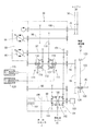
次に、図3及び図4を参照しながら、ミッションケース26等の駆動構造について説明する。図3及び図4に示す如く、ミッションケース26には、1対の直進用油圧ポンプ88及び直進用油圧モータ89を有する直進用の油圧式無段変速機構90と、1対の旋回用油圧ポンプ91及び旋回用油圧モータ92を有する旋回用の油圧式無段変速機構93とを設けている。ミッションケース26の入力軸78に、直進用油圧ポンプ88と旋回用油圧ポンプ91とを連結させて、各ポンプ88,91をそれぞれ駆動するように構成している。また、ミッションケース26の内部には、刈取駆動PTO軸94が水平横向きに配置されている。刈取駆動PTO軸94は、直進用油圧モータ89によって駆動される。ミッションケース26からこの左外側に刈取駆動PTO軸94の一端側を突設している。刈取り入力軸45に刈取駆動ベルト95を介して刈取駆動PTO軸94を連結している。   Next, the drive structure of the mission case 26 and the like will be described with reference to FIGS. As shown in FIGS. 3 and 4, the mission case 26 includes a linear hydraulic stepless transmission mechanism 90 having a pair of linear hydraulic pumps 88 and a linear hydraulic motor 89, and a pair of swing hydraulic pumps. 91 and a turning hydraulic continuously variable transmission mechanism 93 having a turning hydraulic motor 92. A straight traveling hydraulic pump 88 and a turning hydraulic pump 91 are connected to an input shaft 78 of the mission case 26 to drive the pumps 88 and 91, respectively. Further, a cutting drive PTO shaft 94 is disposed horizontally and horizontally inside the mission case 26. The reaping drive PTO shaft 94 is driven by a straight advance hydraulic motor 89. One end side of the cutting drive PTO shaft 94 projects from the transmission case 26 to the left outer side. A cutting drive PTO shaft 94 is connected to the cutting input shaft 45 via a cutting drive belt 95.

図4に示す如く、ミッションケース26の内部には、入力軸78と平行に、直進用油圧ポンプ軸96と、直進用油圧モータ軸97と、刈取駆動PTO軸94と、カウンタ軸98と、直進用変速出力軸99とが配置されている。入力軸78に入力ギヤ100を介して直進用油圧ポンプ軸96を連結している。直進用油圧ポンプ軸96によって直進用油圧ポンプ88が駆動され、直進用油圧モータ89によって直進用油圧モータ軸97が駆動され、直進用油圧ポンプ軸96の回転出力が直進用油圧ポンプ88によって無段階に変速され、直進用油圧モータ軸97によって二段階(高速、低速)に変速されて、直進用油圧モータ軸97に伝達されるように構成している。   As shown in FIG. 4, in the transmission case 26, parallel to the input shaft 78, a straight traveling hydraulic pump shaft 96, a straight traveling hydraulic motor shaft 97, a cutting drive PTO shaft 94, a counter shaft 98, and a straight travel A variable speed output shaft 99 is arranged. A linear hydraulic pump shaft 96 is connected to the input shaft 78 via the input gear 100. The straight hydraulic pump 88 is driven by the straight hydraulic pump shaft 96, the straight hydraulic motor shaft 97 is driven by the straight hydraulic motor 89, and the rotation output of the straight hydraulic pump shaft 96 is stepless by the straight hydraulic pump 88. The speed is shifted in two stages (high speed and low speed) by the straight traveling hydraulic motor shaft 97 and transmitted to the straight traveling hydraulic motor shaft 97.

図4に示す如く、直進用油圧モータ軸97にカウンタギヤ101を介してカウンタ軸98を連結している。カウンタ軸98に直進用変速出力軸99を連結する副変速ギヤ機構102を備える。副変速ギヤ機構102は、副変速低速ギヤ103と、副変速高速ギヤ104と、副変速シフタ105とを有する。副変速レバー15の操作によって、中立位置(出力が零の位置)、又は副変速低速ギヤ103に係止する低速出力位置、又は副変速高速ギヤ104に係止する高速出力位置に、副変速シフタ105が移動して、出力が零の中立又は低速出力又は高速出力のいずれかの変速モードに副変速ギヤ機構102が切換えられるように構成している。換言すると、副変速シフタ105が中立位置のときに直進用変速出力軸99が停止し、副変速シフタ105が低速出力位置のときに直進用変速出力軸99が低速(作業速度)で作動し、副変速シフタ105が高速出力位置のときに直進用変速出力軸99が高速(路上走行速度)で作動するように構成している。   As shown in FIG. 4, a countershaft 98 is connected to a straight hydraulic motor shaft 97 via a counter gear 101. A sub-transmission gear mechanism 102 is provided that connects the straight-shift transmission output shaft 99 to the counter shaft 98. The auxiliary transmission gear mechanism 102 includes an auxiliary transmission low speed gear 103, an auxiliary transmission high speed gear 104, and an auxiliary transmission shifter 105. By operating the auxiliary transmission lever 15, the auxiliary transmission shifter is moved to a neutral position (a position where the output is zero), a low-speed output position that is engaged with the auxiliary transmission low-speed gear 103, or a high-speed output position that is engaged with the auxiliary transmission high-speed gear 104. The sub-transmission gear mechanism 102 is configured to be switched to a shift mode of neutral or low-speed output or high-speed output with zero output. In other words, the linear shift output shaft 99 stops when the sub-shift shifter 105 is in the neutral position, and the linear shift output shaft 99 operates at a low speed (working speed) when the sub-shift shifter 105 is in the low-speed output position. When the auxiliary shift shifter 105 is at the high-speed output position, the straight-shift transmission output shaft 99 is configured to operate at a high speed (road travel speed).

また、直進用変速出力軸99の回転出力が直進用変速出力ギヤ106を介して左右の走行クローラ2に伝達され、直進用変速出力軸99の回転出力によって左右の走行クローラ2が駆動されて、走行機体1が前進方向又は後進方向に移動するように構成している。なお、直進用変速出力軸99上には、左右の走行クローラ2を制動するパーキングブレーキ107と、左右の走行クローラ2の駆動速度(走行機体1の移動速度、車速)を検出する車速センサ108とが配置されている。   In addition, the rotational output of the straight traveling speed change output shaft 99 is transmitted to the left and right traveling crawlers 2 via the straight traveling speed change output gear 106, and the left and right traveling crawlers 2 are driven by the rotational output of the straight traveling speed change output shaft 99. The traveling machine body 1 is configured to move in the forward direction or the reverse direction. A linear brake output shaft 99 includes a parking brake 107 that brakes the left and right traveling crawlers 2, and a vehicle speed sensor 108 that detects the driving speed of the left and right traveling crawlers 2 (the moving speed of the traveling machine body 1 and the vehicle speed). Is arranged.

図4に示す如く、エンジンの出力を変速する第1変速手段としての直進用油圧ポンプ88と、直進用油圧ポンプ88の出力を変速する第2変速手段としての直進用油圧モータ89と、直進用油圧モータ89の出力を変速する第3変速手段としての副変速ギヤ機構102とが、ミッションケース26に配置されている。また、ミッションケース26の内部に、直進用油圧モータ89の出力側の直進用油圧モータ軸97に刈取駆動PTO軸94を連結するPTOクラッチ機構110と、直進用油圧ポンプ88の入力側の直進用油圧ポンプ軸96に刈取駆動PTO軸94を連結する一定回転クラッチ機構111とが設けられている。   As shown in FIG. 4, a linear hydraulic pump 88 as a first transmission means for shifting the output of the engine, a linear hydraulic motor 89 as a second transmission means for shifting the output of the linear hydraulic pump 88, and a linear movement An auxiliary transmission gear mechanism 102 as third transmission means for changing the output of the hydraulic motor 89 is disposed in the mission case 26. Further, in the transmission case 26, a PTO clutch mechanism 110 for connecting a cutting drive PTO shaft 94 to a linear hydraulic motor shaft 97 on the output side of the linear hydraulic motor 89, and a linear drive on the input side of the linear hydraulic pump 88. A constant-rotation clutch mechanism 111 that connects the cutting drive PTO shaft 94 to the hydraulic pump shaft 96 is provided.

即ち、直進用油圧モータ89の出力側から、PTOクラッチ機構110と刈取駆動PTO軸94とを介して、刈取装置3(農作業部)にエンジン20の出力を伝達して、PTOクラッチ機構110の車速同調速度の出力によって刈取り入力軸45が回転駆動されるように構成している。また、直進用油圧ポンプ88の入力側から、一定回転クラッチ機構111と刈取駆動PTO軸94とを介して、刈取装置3にエンジン20の出力を伝達して、一定回転クラッチ機構111の一定回転速度の出力によって刈取り入力軸45が回転駆動されるように構成している。   That is, the output of the engine 20 is transmitted from the output side of the straight traveling hydraulic motor 89 to the reaping device 3 (agricultural work section) via the PTO clutch mechanism 110 and the reaping drive PTO shaft 94, and the vehicle speed of the PTO clutch mechanism 110 is increased. The cutting input shaft 45 is configured to be rotationally driven by the output of the tuning speed. Further, the output of the engine 20 is transmitted from the input side of the straight hydraulic pump 88 to the reaping device 3 via the constant rotation clutch mechanism 111 and the reaping drive PTO shaft 94, so that the constant rotational speed of the constant rotation clutch mechanism 111 is increased. The cutting input shaft 45 is configured to be rotationally driven by the output of.

図4に示す如く、PTOクラッチ機構110は、PTOクラッチギヤ112と、PTOクラッチシフタ114とを有する。PTOクラッチ油圧シリンダ115の切換制御によって、中立位置(出力が零の位置)、又はPTOクラッチギヤ112に係止する車速同調出力位置に、PTOクラッチシフタ114が移動するように構成している。換言すると、PTOクラッチ機構110は、直進用油圧モータ89の出力を車速同調出力として刈取駆動PTO軸94に出力するPTO作動状態と、直進用油圧モータ89の出力を切断するPTO停止(PTOクラッチ切り)状態とに切換可能に構成している。   As shown in FIG. 4, the PTO clutch mechanism 110 includes a PTO clutch gear 112 and a PTO clutch shifter 114. By switching control of the PTO clutch hydraulic cylinder 115, the PTO clutch shifter 114 is moved to a neutral position (a position where the output is zero) or a vehicle speed synchronized output position locked to the PTO clutch gear 112. In other words, the PTO clutch mechanism 110 outputs a PTO operation state in which the output of the straight traveling hydraulic motor 89 is output to the cutting drive PTO shaft 94 as a vehicle speed synchronization output, and a PTO stop (PTO clutch disengagement) that disconnects the output of the straight traveling hydraulic motor 89. ) Can be switched to a state.

即ち、PTOクラッチ油圧シリンダ115の切換制御によって、出力が零の中立、又は車速同調出力のいずれかのモードに、PTOクラッチ機構110が切換えられるように構成している。したがって、直進用油圧モータ89から出力されている場合、PTOクラッチシフタ114が中立位置のときに刈取駆動PTO軸94が停止し、PTOクラッチシフタ114が車速同調出力位置のときに刈取駆動PTO軸94が作動する。その結果、PTOクラッチ機構110からの車速同調出力が刈取駆動PTO軸94を介して刈取り入力軸45に伝達されて、刈取り入力軸45を介して、車速同調出力(走行機体1の移動速度)によって刈取装置3が作動することになる。   That is, the PTO clutch mechanism 110 is configured to be switched to a neutral output mode or a vehicle speed synchronized output mode by switching control of the PTO clutch hydraulic cylinder 115. Therefore, when output from the straight-travel hydraulic motor 89, the cutting drive PTO shaft 94 stops when the PTO clutch shifter 114 is in the neutral position, and the cutting drive PTO shaft 94 when the PTO clutch shifter 114 is in the vehicle speed synchronization output position. Operates. As a result, the vehicle speed synchronization output from the PTO clutch mechanism 110 is transmitted to the cutting input shaft 45 via the cutting drive PTO shaft 94, and the vehicle speed synchronization output (moving speed of the traveling vehicle body 1) is transmitted via the cutting input shaft 45. The reaping device 3 is activated.

また、PTOクラッチシフタ114は、PTOクラッチ用の一方向回転クラッチ116を介して刈取駆動PTO軸94に軸支されている。即ち、直進用油圧モータ軸97における回転のうち、走行機体1を前進移動する方向の回転は、一方向回転クラッチ116を介して刈取駆動PTO軸94に伝達する。一方、直進用油圧モータ軸97における回転のうち、走行機体1を後進移動する方向の回転は、刈取駆動PTO軸94に伝達しないという構成である。加えて、刈取駆動PTO軸94から直進用油圧モータ軸97への方向には、PTOクラッチ機構110を介して、回転を伝達しないという構成である。   Further, the PTO clutch shifter 114 is pivotally supported by a reaping drive PTO shaft 94 via a one-way rotation clutch 116 for a PTO clutch. That is, of the rotations in the straight traveling hydraulic motor shaft 97, the rotation in the direction in which the traveling machine body 1 moves forward is transmitted to the cutting drive PTO shaft 94 via the one-way rotation clutch 116. On the other hand, of the rotations in the straight traveling hydraulic motor shaft 97, the rotation in the direction in which the traveling machine body 1 moves backward is not transmitted to the cutting drive PTO shaft 94. In addition, the rotation is not transmitted through the PTO clutch mechanism 110 in the direction from the reaping drive PTO shaft 94 to the linear hydraulic motor shaft 97.

また、一定回転クラッチ機構111は、一定回転クラッチギヤ118と、一定回転クラッチシフタ119とを有する。一定回転クラッチ油圧シリンダ120の切換制御によって、中立位置(出力が零の位置)、又は一定回転クラッチギヤ118に係止する一定回転位置に、一定回転クラッチシフタ119が移動するように構成している。換言すると、一定回転クラッチ機構111は、刈取装置3の駆動に必要な最高回転数を保持する一定回転作動状態と、直進用油圧モータ軸97の出力を切断するPTO停止(PTOクラッチ切り)状態とに切換可能に構成している。なお、図8に示す如く、一定回転クラッチ機構111から刈取り入力軸45に伝達される一定回転出力は、刈取作業を実行する車速同調出力よりも高い回転数の高速側回転出力(高速側一定回転速度V2=1.6m/s)である。   The constant rotation clutch mechanism 111 includes a constant rotation clutch gear 118 and a constant rotation clutch shifter 119. By the switching control of the constant rotation clutch hydraulic cylinder 120, the constant rotation clutch shifter 119 is configured to move to a neutral position (a position where the output is zero) or to a constant rotation position where the constant rotation clutch gear 118 is locked. . In other words, the constant rotation clutch mechanism 111 has a constant rotation operation state in which the maximum number of rotations necessary for driving the reaping device 3 is maintained, and a PTO stop state (PTO clutch disengagement) state in which the output of the straight traveling hydraulic motor shaft 97 is disconnected. It can be switched to. As shown in FIG. 8, the constant rotation output transmitted from the constant rotation clutch mechanism 111 to the cutting input shaft 45 is a high-speed rotation output (high-speed constant rotation) at a higher rotational speed than the vehicle speed tuning output for executing the cutting operation. Speed V2 = 1.6 m / s).

即ち、一定回転クラッチ油圧シリンダ120の切換制御によって、出力が零の中立、又は一定回転出力(高速カットモード)のいずれかの一定回転出力モードに、一定回転クラッチ機構111が切換えられるように構成している。換言すると、直進用油圧ポンプ軸96が駆動されている場合、一定回転クラッチシフタ119が中立位置のときに刈取駆動PTO軸94が停止し、一定回転クラッチシフタ119が一定回転出力位置のときに刈取駆動PTO軸94が高速側一定回転速度V2(高速カット速度)で作動するように構成している。その結果、PTOクラッチ機構110からの車速同調出力の最高速よりも早い一定回転数の回転出力が一定回転クラッチギヤ118を介して刈取駆動PTO軸94に伝達されることになる。   That is, the constant rotation clutch mechanism 111 can be switched to a constant rotation output mode of either a neutral output of zero or a constant rotation output (high-speed cut mode) by switching control of the constant rotation clutch hydraulic cylinder 120. ing. In other words, when the straight hydraulic pump shaft 96 is driven, the reaping drive PTO shaft 94 stops when the constant rotation clutch shifter 119 is in the neutral position, and when the constant rotation clutch shifter 119 is at the constant rotation output position. The drive PTO shaft 94 is configured to operate at a high speed side constant rotational speed V2 (high speed cut speed). As a result, a rotational output at a constant rotational speed that is faster than the maximum speed of the vehicle speed tuning output from the PTO clutch mechanism 110 is transmitted to the cutting drive PTO shaft 94 via the constant rotational clutch gear 118.

したがって、PTOクラッチ機構110からの車速同調出力よりも早い一定回転クラッチギヤ118からの高速側一定回転速度V2(一定回転数の出力)によって、刈取装置3を作動できる。走行機体1の移動速度(車速)を極めて高速にした刈取作業のときに、車速同調速度での駆動から高速側一定回転速度V2での駆動に切換えて刈取装置3を作動させ、刈取装置3に発生する騒音を低減できる。一方、走行機体1の移動速度が車速同調速度の範囲内であっても、高速側一定回転速度V2で刈取装置3を作動させることによって、圃場に倒伏している穀稈をスムーズに引起して刈取ることができ、倒伏穀稈の刈取り作業性等を向上できる。   Therefore, the reaping device 3 can be operated by the high speed side constant rotational speed V2 (output of a constant rotational speed) from the constant rotational clutch gear 118 that is faster than the vehicle speed synchronization output from the PTO clutch mechanism 110. At the time of the cutting operation in which the traveling speed (vehicle speed) of the traveling machine body 1 is extremely high, the cutting device 3 is operated by switching from the driving at the vehicle speed synchronization speed to the driving at the high speed side constant rotational speed V2, and the cutting device 3 Noise generated can be reduced. On the other hand, even if the traveling speed of the traveling machine 1 is within the range of the vehicle speed synchronization speed, the reaping apparatus 3 is operated at the high speed side constant rotational speed V2, thereby causing the cereals lying in the field to be smoothly caused. It can be harvested, and the workability of harvesting cereals can be improved.

また、一定回転クラッチシフタ119は、一定回転クラッチ用の一方向回転クラッチ121を介して刈取駆動PTO軸94に軸支されている。直進用油圧ポンプ軸96の回転は、一方向回転クラッチ121を介して刈取駆動PTO軸94に伝達されるように構成している。即ち、直進用油圧ポンプ軸96から刈取駆動PTO軸94への方向には、一定回転クラッチ機構111を介して、回転を伝達する。一方、刈取駆動PTO軸94から直進用油圧ポンプ軸96への方向には、一定回転クラッチ機構111を介して、回転を伝達しないという構成である。   Further, the constant rotation clutch shifter 119 is pivotally supported by the cutting drive PTO shaft 94 via a one-way rotation clutch 121 for the constant rotation clutch. The rotation of the rectilinear hydraulic pump shaft 96 is transmitted to the cutting drive PTO shaft 94 via the one-way rotation clutch 121. That is, the rotation is transmitted through the constant rotation clutch mechanism 111 in the direction from the straight hydraulic pump shaft 96 to the cutting drive PTO shaft 94. On the other hand, the rotation is not transmitted through the constant rotation clutch mechanism 111 in the direction from the cutting drive PTO shaft 94 to the straight hydraulic pump shaft 96.

その結果、PTOクラッチシフタ114及びPTOクラッチ用の一方向回転クラッチ116を介して伝達されるPTOクラッチ機構110の回転出力、又は一定回転クラッチシフタ119及び一定回転クラッチ用の一方向回転クラッチ121を介して伝達される一定回転クラッチ機構111の回転出力のうち、高速側の回転出力によって、刈取駆動PTO軸94を介して刈取り入力軸45が駆動されて、刈取装置3が作動する。即ち、PTOクラッチ機構110の車速同調速度の回転出力、又は一定回転クラッチ機構111の高速側一定回転出力のいずれか一方によって、刈取駆動PTO軸94を介して刈取り入力軸45が駆動される。したがって、PTOクラッチ機構110の車速同調速度の回転出力と、一定回転クラッチ機構111の一定回転出力とが、同時に、刈取駆動PTO軸94に伝達されない。   As a result, the rotational output of the PTO clutch mechanism 110 transmitted through the PTO clutch shifter 114 and the one-way rotation clutch 116 for the PTO clutch, or the one-way rotation clutch 121 for the constant rotation clutch shifter 119 and the constant rotation clutch. The cutting input shaft 45 is driven via the cutting drive PTO shaft 94 by the rotation output on the high speed side among the rotation outputs of the constant rotation clutch mechanism 111 transmitted in this manner, and the cutting device 3 is operated. That is, the cutting input shaft 45 is driven via the cutting drive PTO shaft 94 by either the rotation output of the vehicle speed synchronization speed of the PTO clutch mechanism 110 or the high-speed constant rotation output of the constant rotation clutch mechanism 111. Therefore, the rotation output of the vehicle speed synchronization speed of the PTO clutch mechanism 110 and the constant rotation output of the constant rotation clutch mechanism 111 are not transmitted to the reaping drive PTO shaft 94 at the same time.

図3及び図4に示すように、流し込みベルト122、流し込みクラッチ123、流し込みプーリ124を介して、刈取り入力軸45に脱穀駆動軸80を連結している。オペレータが流し込みペダル(図示省略)を足踏み操作して、流し込みクラッチ123を継続作動したときに、流し込みベルト122及び流し込みプーリ124を介して、エンジン20からの一定回転出力が脱穀駆動軸80から刈取り入力軸45に伝達されるように構成している。なお、図8に示す如く、脱穀駆動軸80から流し込みベルト122を介して刈取り入力軸45に伝達される一定回転出力は、刈取作業の維持に必要な一定回転数の低速側回転出力(流し込み一定回転速度V1=0.8m/s)であって、一定回転クラッチ機構111からの一定回転出力(高速側一定回転速度V2)の約半分の回転数に設定されている。   As shown in FIGS. 3 and 4, a threshing drive shaft 80 is connected to the cutting input shaft 45 through a pouring belt 122, a pouring clutch 123, and a pouring pulley 124. When the operator depresses a pouring pedal (not shown) and the pouring clutch 123 is continuously operated, a constant rotational output from the engine 20 is input from the threshing drive shaft 80 via the pouring belt 122 and the pouring pulley 124. It is configured to be transmitted to the shaft 45. As shown in FIG. 8, the constant rotation output transmitted from the threshing drive shaft 80 to the cutting input shaft 45 via the pouring belt 122 is a low speed side rotating output (fixed pouring constant) necessary for maintaining the mowing operation. (Rotational speed V1 = 0.8 m / s), and the rotational speed is set to about half the constant rotational output from the constant rotational clutch mechanism 111 (high-speed constant rotational speed V2).

その結果、刈取作業中、圃場の枕地に走行機体が到達して、次行程の作業場所に走行機体1を方向転換させる場合等において、走行機体1の移動速度が遅くなったり、走行機体1が停止したり、走行機体1を後進移動させても、オペレータが流し込みペダルを足踏み操作することによって、流し込みベルト122及び流し込みプーリ124からの一定回転数の低速側回転出力が刈取り入力軸45に伝達され、刈取り入力軸45を介して刈取装置3が流し込み一定回転速度V1で作動することになる。穀稈の搬送等の刈取作業を維持でき、圃場の枕地での方向転換作業性等を向上できる。   As a result, during the cutting operation, when the traveling machine body reaches the headland in the field and changes the direction of the traveling machine body 1 to the work place of the next stroke, the traveling speed of the traveling machine body 1 becomes slow, or the traveling machine body 1 Even when the vehicle is stopped or the traveling body 1 is moved backward, when the operator depresses the pouring pedal, the low-speed rotation output at a constant rotational speed from the pouring belt 122 and the pouring pulley 124 is transmitted to the cutting input shaft 45. Then, the cutting device 3 flows through the cutting input shaft 45 and operates at a constant rotational speed V1. Cutting operations such as the transportation of cereals can be maintained, and the direction changing workability at the headland in the field can be improved.

また、流し込みクラッチ用の一方向回転クラッチ109を介して、刈取り入力軸45に流し込みプーリ124を軸支している。即ち、脱穀駆動軸80から刈取り入力軸45への方向には、一方向回転クラッチ109を介して、回転を伝達するが、刈取り入力軸45から脱穀駆動軸80への方向には、一方向回転クラッチ109を介して、回転を伝達しないという構成である。その結果、PTOクラッチ機構110からの車速同調回転出力又は一定回転クラッチ機構111からの高速側一定回転出力によって刈取駆動PTO軸94が駆動されている状態下で、流し込みクラッチ123を継続作動したときに、刈取駆動PTO軸94の回転出力、又は流し込みプーリ124の回転出力のうち、高速側の回転出力によって、刈取り入力軸45が駆動されて、刈取装置3が作動する。   Further, a flow pulley 124 is pivotally supported on the cutting input shaft 45 via a one-way rotation clutch 109 for the flow clutch. In other words, rotation is transmitted in the direction from the threshing drive shaft 80 to the cutting input shaft 45 via the one-way rotation clutch 109, but in one direction in the direction from the cutting input shaft 45 to the threshing driving shaft 80. In this configuration, rotation is not transmitted via the clutch 109. As a result, when the pouring clutch 123 is continuously operated in a state where the cutting drive PTO shaft 94 is driven by the vehicle speed synchronized rotation output from the PTO clutch mechanism 110 or the high speed side constant rotation output from the constant rotation clutch mechanism 111. Of the rotational output of the cutting drive PTO shaft 94 or the rotational output of the flow-in pulley 124, the cutting input shaft 45 is driven by the rotational output on the high speed side, and the cutting device 3 operates.

次に、図5を参照して、直進用油圧無段変速機構90と、旋回用油圧無段変速機構93の構造を説明する。図5に示すように、旋回用油圧ポンプ91のポンプ軸にチャージポンプ125を連結している。直進用油圧ポンプ88及び直進用油圧モータ89は、閉油圧回路にて油圧接続され、チャージポンプ125のチャージ油圧がその閉油圧回路に供給されるように構成している。同様に、旋回用油圧ポンプ91及び旋回用油圧モータ92は、閉油圧回路にて油圧接続され、チャージポンプ125のチャージ油圧がその閉油圧回路に供給されるように構成している。ミッションケース26の入力軸78に伝達されたエンジン20の回転駆動力が、直進用油圧無段変速機構90又は旋回用油圧無段変速機構93によって変速された後、左右の車軸27に伝達され、左右の車軸27を介して左右の走行クローラ2がそれぞれ駆動されるように構成している。   Next, referring to FIG. 5, the structures of the straight-traveling hydraulic continuously variable transmission mechanism 90 and the turning hydraulic continuously variable transmission mechanism 93 will be described. As shown in FIG. 5, the charge pump 125 is connected to the pump shaft of the turning hydraulic pump 91. The rectilinear hydraulic pump 88 and the rectilinear hydraulic motor 89 are hydraulically connected by a closed hydraulic circuit, and the charge hydraulic pressure of the charge pump 125 is supplied to the closed hydraulic circuit. Similarly, the swing hydraulic pump 91 and the swing hydraulic motor 92 are hydraulically connected by a closed hydraulic circuit, and the charge hydraulic pressure of the charge pump 125 is supplied to the closed hydraulic circuit. The rotational driving force of the engine 20 transmitted to the input shaft 78 of the mission case 26 is transmitted to the left and right axles 27 after being shifted by the straight traveling hydraulic continuously variable transmission mechanism 90 or the turning hydraulic continuously variable transmission mechanism 93. The left and right traveling crawlers 2 are configured to be driven via the left and right axles 27, respectively.

図5に示す如く、直進用油圧ポンプ88の斜板88aの傾斜角度を変更して出力調整する主変速シリンダ126と、主変速レバー14及び操向ハンドル11に連結させて切換える主変速バルブ127と、直進用油圧ポンプ88の出力を一定量減速する減速バルブ128とを設け、チャージポンプ125を主変速バルブ127又は減速バルブ128を介して主変速シリンダ126に油圧接続させている。その結果、主変速レバー14によって主変速バルブ127を切換え、主変速シリンダ126を作動させて、直進用油圧ポンプ88の斜板88aの角度を変更させ、直進用油圧モータ89のモータ軸97の回転数を、前進方向又は後進方向に無段階に変化させることになる。   As shown in FIG. 5, a main transmission cylinder 126 that adjusts the output by changing the inclination angle of the swash plate 88a of the straight hydraulic pump 88, and a main transmission valve 127 that is connected to the main transmission lever 14 and the steering handle 11 for switching. And a deceleration valve 128 that decelerates the output of the straight hydraulic pump 88 by a certain amount, and the charge pump 125 is hydraulically connected to the main transmission cylinder 126 via the main transmission valve 127 or the reduction valve 128. As a result, the main transmission valve 127 is switched by the main transmission lever 14 and the main transmission cylinder 126 is operated to change the angle of the swash plate 88a of the linear hydraulic pump 88, thereby rotating the motor shaft 97 of the linear hydraulic motor 89. The number is continuously changed in the forward direction or the backward direction.

また、直進用油圧モータ89の斜板89aの角度を変更して出力調整する副変速シリンダ129と、油圧副変速高速ソレノイド130a及び油圧副変速低速ソレノイド130bを有する電磁副変速バルブ130とを設けている。前記チャージポンプ125に電磁副変速バルブ130を介して副変速シリンダ129を油圧接続させている。副変速バルブ130が中立の切換位置のときには、油タンクであるミッションケース26に副変速シリンダ129が短絡され、直進用油圧モータ89の斜板89aが、直進用油圧ポンプ88の油圧(閉回路油圧)によって最大傾斜位置に維持されるように構成している。   Further, a sub-transmission cylinder 129 that adjusts the output by changing the angle of the swash plate 89a of the straight traveling hydraulic motor 89, and an electromagnetic sub-transmission valve 130 having a hydraulic sub-transmission high-speed solenoid 130a and a hydraulic sub-transmission low-speed solenoid 130b are provided. Yes. An auxiliary transmission cylinder 129 is hydraulically connected to the charge pump 125 through an electromagnetic auxiliary transmission valve 130. When the sub-transmission valve 130 is in the neutral switching position, the sub-transmission cylinder 129 is short-circuited to the transmission case 26 that is an oil tank, and the swash plate 89a of the linear hydraulic motor 89 is hydraulically connected to the hydraulic pump 88 (closed circuit hydraulic pressure). ) To maintain the maximum tilt position.

一方、副変速バルブ130が中立位置以外の切換位置に切換られたときには、チャージポンプ125の油圧が副変速バルブ130を介して副変速シリンダ129に印加され、直進用油圧ポンプ88の油圧(閉回路油圧)に関係なく、直進用油圧モータ89の斜板89aの角度が副変速シリンダ129によって強制的に変更され、直進用油圧モータ軸97の回転数を高速側又は低速側に変化させることになる。即ち、直進用油圧モータ89の斜板89aの角度を変更する操作、換言すると、副変速バルブ130を切換える副変速操作によって、直進用油圧モータ89の出力回転数を高速側又は低速側に切換えるように構成している。   On the other hand, when the sub-transmission valve 130 is switched to a switching position other than the neutral position, the hydraulic pressure of the charge pump 125 is applied to the sub-transmission cylinder 129 via the sub-transmission valve 130, and the hydraulic pressure (closed circuit) of the straight traveling hydraulic pump 88 is applied. Regardless of the hydraulic pressure), the angle of the swash plate 89a of the straight traveling hydraulic motor 89 is forcibly changed by the auxiliary transmission cylinder 129, and the rotational speed of the straight traveling hydraulic motor shaft 97 is changed to the high speed side or the low speed side. . That is, an operation for changing the angle of the swash plate 89a of the straight-travel hydraulic motor 89, in other words, a sub-shift operation for switching the sub-shift valve 130, switches the output rotational speed of the straight-travel hydraulic motor 89 to the high speed side or the low speed side. It is configured.

さらに、旋回用油圧ポンプ91の斜板91aの角度を変更して出力調整する旋回シリンダ131を設け、操向ハンドル11又は主変速レバー14によって切換える旋回バルブ132、又は電磁式自動操向バルブ133を介して旋回シリンダ131にチャージポンプ125を油圧接続させている。操向ハンドル11によって旋回バルブ132を切換えることによって、旋回シリンダ131が作動して、旋回用油圧ポンプ91の斜板91aの角度が無段階に変更されることになる。その結果、操向ハンドル11の操作によって旋回用油圧モータ91の出力回転数が無段階に変化したり、旋回用油圧モータ91の出力回転が逆転することになる。即ち、操向ハンドル11の左右方向の回転操作量(操舵角)に比例して斜板91aの角度が変化し、旋回用油圧モータ91の出力回転数が変化したり逆転して、走行機体1の進路(左右旋回角度)が左方向又は右方向に変更されるように構成している。   Further, a turning cylinder 131 for adjusting the output by changing the angle of the swash plate 91a of the turning hydraulic pump 91 is provided, and a turning valve 132 that is switched by the steering handle 11 or the main shift lever 14 or an electromagnetic automatic steering valve 133 is provided. The charge pump 125 is hydraulically connected to the swivel cylinder 131. By switching the turning valve 132 by the steering handle 11, the turning cylinder 131 is operated, and the angle of the swash plate 91a of the turning hydraulic pump 91 is changed steplessly. As a result, the output rotation speed of the turning hydraulic motor 91 changes steplessly by the operation of the steering handle 11, or the output rotation of the turning hydraulic motor 91 is reversed. In other words, the angle of the swash plate 91a changes in proportion to the amount of left and right rotational operation (steering angle) of the steering handle 11, and the output rotational speed of the turning hydraulic motor 91 changes or reverses, so that the traveling machine body 1 The path (left and right turning angle) is changed leftward or rightward.

なお、主変速レバー14が中立以外の変速位置に操作された状態で、操向ハンドル11が直進以外の操舵角位置に操作された場合、主変速レバー14の操作方向(前進、後進)と操作量(増減速)に比例して、直進用油圧ポンプ88の斜板88aの角度(出力油圧)が増減したり反転して、油圧モータ89を、増速又は減速させたり、正転又は逆転させ、前進速度又は後進速度(直進移動速度と進行方向)が変更されることになる。また、主変速レバー14の操作量に比例して旋回用油圧ポンプ91の出力油圧が変化(増減)するように構成したものであり、主変速レバー14の高速側走行変速によって旋回半径が自動的に小さくなり、且つ主変速レバー14の低速側走行変速によって旋回半径が自動的に大きくなるように構成している。したがって、操向ハンドル11が直進以外の一定操舵角位置に保持されているときに、主変速レバー14が中立以外の変速位置に操作された場合、主変速レバー14の変速操作位置(直進移動速度)に関係なく、左右走行クローラ2の旋回半径が略一定に維持されて、走行機体1の移動速度(作業車速)を変更できたり、未刈り穀稈列等に機体を沿わせるように、走行機体1の進路を修正できる。   When the steering handle 11 is operated to a steering angle position other than straight travel while the main speed change lever 14 is operated to a speed change position other than neutral, the operation direction (forward, reverse) and operation of the main speed change lever 14 are operated. In proportion to the amount (acceleration / deceleration), the angle (output hydraulic pressure) of the swash plate 88a of the straight hydraulic pump 88 increases / decreases or reverses, and the hydraulic motor 89 is increased / decreased, rotated forward / reversely. The forward speed or the reverse speed (the straight movement speed and the traveling direction) is changed. Further, the output hydraulic pressure of the turning hydraulic pump 91 changes (increases / decreases) in proportion to the operation amount of the main transmission lever 14, and the turning radius is automatically set by the high-speed traveling shift of the main transmission lever 14. The turning radius is automatically increased by the low-speed traveling shift of the main transmission lever 14. Therefore, if the main shift lever 14 is operated to a shift position other than neutral while the steering handle 11 is held at a constant steering angle position other than straight travel, the shift operation position (straight travel speed) of the main shift lever 14 ) Regardless of), the turning radius of the left and right traveling crawler 2 is maintained substantially constant so that the traveling speed (working vehicle speed) of the traveling machine body 1 can be changed, or the machine body is moved along an uncut grain row, etc. The course of Aircraft 1 can be corrected.

一方、操向ハンドル11の操作量(操舵角)に比例させて、主変速バルブ27の制御によって直進用油圧ポンプ88の出力を変化させ、且つ旋回バルブ132の制御によって旋回用油圧ポンプ91の出力を変化させるように構成している。即ち、操向ハンドル11の操舵角を大きくして、走行機体1の旋回半径を小さくしたときに、その旋回半径(操舵角)に比例させて走行機体1の移動速度(車速)を減速させ乍ら、左右の走行クローラ2の速度差を大きくし、走行機体1を左右に旋回させることができる。連続的に穀稈を刈取って脱穀する収穫作業において、左右走行クローラ2の駆動速度を変更して、条合せ等の進路修正や、圃場枕地でのスピンターン等の方向転換を実行できる。なお、主変速レバー14が中立のときには、操向ハンドル11の操作に関係なく、旋回バルブ132が中立維持され、旋回用油圧ポンプ91の油圧出力が略零に保たれ、旋回用油圧モータ92を停止維持するように構成している。   On the other hand, in accordance with the operation amount (steering angle) of the steering handle 11, the output of the straight hydraulic pump 88 is changed by the control of the main speed change valve 27, and the output of the swing hydraulic pump 91 is controlled by the control of the swing valve 132. It is configured to change. That is, when the steering angle of the steering handle 11 is increased and the turning radius of the traveling machine body 1 is reduced, the moving speed (vehicle speed) of the traveling machine body 1 is reduced in proportion to the turning radius (steering angle). Thus, the speed difference between the left and right traveling crawlers 2 can be increased and the traveling machine body 1 can be turned left and right. In a harvesting operation in which cereals are continuously harvested and threshed, the driving speed of the left and right traveling crawlers 2 can be changed to change the course such as alignment and to change the direction such as spin turn on the field headland. When the main transmission lever 14 is neutral, the swing valve 132 is maintained neutral regardless of the operation of the steering handle 11, the hydraulic output of the swing hydraulic pump 91 is maintained at substantially zero, and the swing hydraulic motor 92 is turned on. It is configured to keep stopped.

図5に示す如く、刈取クラッチソレノイド134aを有する電磁刈取クラッチバルブ134と、定速クラッチソレノイド135aを有する電磁一定回転バルブ135とを設けている。上述したチャージポンプ125に電磁刈取クラッチバルブ134を介してPTOクラッチ油圧シリンダ115を油圧接続している。電磁刈取クラッチバルブ134を切換えてPTOクラッチ油圧シリンダ115を作動するように構成している。また、上述したチャージポンプ125に電磁一定回転バルブ135を介して一定回転クラッチ油圧シリンダ120を油圧接続している。電磁一定回転バルブ135を切換えて一定回転クラッチ油圧シリンダ120を作動するように構成している。   As shown in FIG. 5, an electromagnetic reaping clutch valve 134 having a reaping clutch solenoid 134a and an electromagnetic constant rotation valve 135 having a constant speed clutch solenoid 135a are provided. A PTO clutch hydraulic cylinder 115 is hydraulically connected to the charge pump 125 described above via an electromagnetic mowing clutch valve 134. The PTO clutch hydraulic cylinder 115 is operated by switching the electromagnetic mowing clutch valve 134. Further, the constant rotation clutch hydraulic cylinder 120 is hydraulically connected to the charge pump 125 described above via an electromagnetic constant rotation valve 135. The constant rotation clutch hydraulic cylinder 120 is operated by switching the electromagnetic constant rotation valve 135.

なお、PTOクラッチ油圧シリンダ115と、一定回転クラッチ油圧シリンダ120とは、2ポジションシリンダによって形成している。2位置3ポート型の前記バルブ134,135を切換えたときに、チャージポンプ125からの油圧によって、前記シリンダ115,120のピストンが進出位置に保持される。また、前記バルブ134,135が内蔵バネによってアンロード位置に弾圧維持されているときに、前記シリンダ115,120のピストンは、内蔵バネによって退入位置に弾圧保持される。   The PTO clutch hydraulic cylinder 115 and the constant rotation clutch hydraulic cylinder 120 are formed by a two-position cylinder. When the two-position three-port type valves 134 and 135 are switched, the pistons of the cylinders 115 and 120 are held in the advanced positions by the hydraulic pressure from the charge pump 125. Further, when the valves 134 and 135 are maintained in the unload position by the built-in spring, the pistons of the cylinders 115 and 120 are held in the retracted position by the built-in spring.

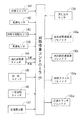
次に、本実施形態の刈取速度制御について説明する。図6は、刈取速度制御手段の機能ブロック図であり、制御プログラムを記憶したROMと各種データを記憶したRAMとを有するマイクロコンピュータ等の刈取作業コントローラ140を備えている。図6に示されるように、マイクロコンピュータで構成する刈取作業コントローラ140の入力側には、脱穀装置5の駆動等を検出する作業スイッチ141と、穀稈引起装置31の穀稈(未刈リ穀稈)又は穀稈搬送装置32の穀稈(刈取穀稈)を検出する穀稈センサ142と、刈取り入力軸45の回転数を検出する刈取り回転センサ143と、上述した車速センサ108と、油圧副変速高速ソレノイド130a又は油圧副変速低速ソレノイド130bのいずれか一方をオンにしたりそれらの両方をオフにして電磁副変速バルブ130を切換える油圧副変速スイッチ144と、刈取クラッチソレノイド134aをオンにして電磁刈取クラッチバルブ134を切換える刈取クラッチスイッチ145と、定速クラッチソレノイド135aをオンにして電磁一定回転バルブ135を切換える一定回転スイッチ146と、定速クラッチソレノイド135aが作動する車速値(走行機体1の移動速度)を設定する定速設定器147と、流し込みクラッチ123の入り操作(クラッチ継続動作)を検出する流し込みセンサ139とを接続している。   Next, the cutting speed control of this embodiment will be described. FIG. 6 is a functional block diagram of the cutting speed control means, which includes a cutting operation controller 140 such as a microcomputer having a ROM storing a control program and a RAM storing various data. As shown in FIG. 6, on the input side of a mowing operation controller 140 configured by a microcomputer, a work switch 141 that detects the driving of the threshing device 5 and the like and the cereal of the cereal wakening device 31 (uncut reashed稈) or a culm sensor 142 for detecting the culm (harvested cereal) of the culm transporting device 32, a reaping rotation sensor 143 for detecting the rotational speed of the reaping input shaft 45, the vehicle speed sensor 108 described above, and the hydraulic auxiliary Either one of the shift high-speed solenoid 130a or the hydraulic sub-shift low-speed solenoid 130b is turned on or both of them are turned off to switch the electromagnetic sub-shift valve 130, and the cutting clutch solenoid 134a is turned on to cut the electromagnetic The cutting clutch switch 145 for switching the clutch valve 134 and the constant speed clutch solenoid 135a are turned on. A constant rotation switch 146 for switching the magnetic constant rotation valve 135, a constant speed setting device 147 for setting a vehicle speed value (moving speed of the traveling machine body 1) at which the constant speed clutch solenoid 135a is operated, and an operation of engaging the flow clutch 123 (clutch continuation) A flow sensor 139 for detecting the operation) is connected.

図6に示す如く、刈取作業コントローラ140の出力側には、上述した油圧副変速高速ソレノイド130a及び油圧副変速低速ソレノイド130bと、刈取クラッチソレノイド134aと、定速クラッチソレノイド135aとを接続している。即ち、上述した各スイッチ144,145,146の手動操作によって、各ソレノイド130a,130b,134a,135aを励磁作動させる一方、車速センサ108の検出値と定速設定器147の設定値とに基づき、定速クラッチソレノイド135aを自動的に励磁作動させるように構成している。   As shown in FIG. 6, on the output side of the mowing operation controller 140, the hydraulic auxiliary transmission high speed solenoid 130a and the hydraulic auxiliary transmission low speed solenoid 130b, the cutting clutch solenoid 134a, and the constant speed clutch solenoid 135a are connected. . That is, the solenoids 130a, 130b, 134a, and 135a are excited by manual operation of the switches 144, 145, and 146 described above, while the detected values of the vehicle speed sensor 108 and the set values of the constant speed setter 147 are used. The constant speed clutch solenoid 135a is automatically excited.

次に、図7は刈取速度制御のフローチャートである。図7を参照して、圃場に植立した穀稈の刈取作業を説明する。作業スイッチ141がオンで(S1yes)、穀稈センサ142がオンのときに(S2yes)、圃場に植立した穀稈を刈取る刈取作業中であると判断され、車速センサ108の検出値と、刈取リ回転センサ143の検出値とが読み込まれる。(S3)また、定速設定器147の設定値が読み込まれる(S4)。車速センサ108の検出値と、刈取リ回転センサ143の検出値と、定速設定器147の設定値とから刈取速度が演算される(S5)。   Next, FIG. 7 is a flowchart of the cutting speed control. With reference to FIG. 7, the cutting operation of the cereals planted in the field will be described. When the work switch 141 is on (S1yes) and the culm sensor 142 is on (S2yes), it is determined that the culm is being harvested and the detected value of the vehicle speed sensor 108 is The value detected by the cutting re-rotation sensor 143 is read. (S3) Also, the set value of the constant speed setter 147 is read (S4). The cutting speed is calculated from the detection value of the vehicle speed sensor 108, the detection value of the cutting rerotation sensor 143, and the setting value of the constant speed setter 147 (S5).

また、オペレータが刈取クラッチスイッチ145を操作して、刈取クラッチソレノイド134aを励磁させ、電磁刈取クラッチバルブ134を切換え、PTOクラッチ油圧シリンダ115を作動させ、PTOクラッチ機構110のPTOクラッチギヤ112が刈取駆動PTO軸94に係合され、刈取クラッチオンの状態になった場合(S6yes)、PTOクラッチギヤ112を介して刈取駆動PTO軸94が作動するという刈取装置3の車速同調駆動制御が実行される(S7)。その結果、走行機体1の移動速度(車速)に同調して刈取装置3の作動速度が変化する。即ち、刈取装置3が車速同調速度にて駆動されて刈取作業が行われる。   Further, the operator operates the cutting clutch switch 145 to excite the cutting clutch solenoid 134a, switches the electromagnetic cutting clutch valve 134, operates the PTO clutch hydraulic cylinder 115, and the PTO clutch gear 112 of the PTO clutch mechanism 110 is driven to cut. When it is engaged with the PTO shaft 94 and the cutting clutch is turned on (S6yes), the vehicle speed synchronized drive control of the cutting device 3 is performed in which the cutting drive PTO shaft 94 is operated via the PTO clutch gear 112 ( S7). As a result, the operating speed of the reaping device 3 changes in synchronization with the moving speed (vehicle speed) of the traveling machine body 1. That is, the cutting operation is performed by driving the cutting device 3 at the vehicle speed synchronization speed.

一方、オペレータが一定回転スイッチ146を操作して、定速クラッチソレノイド135aを励磁させ、電磁一定回転バルブ135を切換え、一定回転クラッチ油圧シリンダ120を作動させ、一定回転クラッチ機構111の一定回転クラッチギヤ118が刈取駆動PTO軸94に係合され、一定回転クラッチオンの状態になった場合(S8yes)、一定回転クラッチギヤ118を介して刈取駆動PTO軸94が作動するという刈取装置3の刈取速度の一定回転制御が実行される(S9)。その結果、走行機体1の移動速度(車速)に関係なく、刈取装置3の作動速度が高速側一定回転速度V2に維持される。即ち、ステップ7の車速同調駆動制御による刈取装置3の作動速度の最高速度と同じかそれ以上の高速の高速側一定回転速度V2で、刈取装置3が駆動されて刈取作業が行われる。   On the other hand, the operator operates the constant rotation switch 146 to excite the constant speed clutch solenoid 135a, switches the electromagnetic constant rotation valve 135, operates the constant rotation clutch hydraulic cylinder 120, and operates the constant rotation clutch gear 111 of the constant rotation clutch mechanism 111. When 118 is engaged with the reaping drive PTO shaft 94 and the constant rotation clutch is turned on (S8 yes), the reaping speed of the reaping device 3 that the reaping drive PTO shaft 94 is operated via the constant rotation clutch gear 118 is set. Constant rotation control is executed (S9). As a result, regardless of the moving speed (vehicle speed) of the traveling machine body 1, the operating speed of the reaping device 3 is maintained at the high speed side constant rotational speed V2. That is, the reaping device 3 is driven and the reaping operation is performed at a high speed side constant rotational speed V2 that is equal to or higher than the maximum operating speed of the reaping device 3 by the vehicle speed synchronous drive control in step 7.

他方、刈取クラッチスイッチ145又は一定回転スイッチ146がオフで、ステップ9における刈取装置3の刈取速度の一定回転制御が実行されていないときに、オペレータが流し込みペダル(図示省略)を足踏み操作して、流し込みクラッチ123をオン作動させた場合、流し込みベルト122及び流し込みプーリ124からの一定回転数の低速側回転出力が刈取り入力軸45に伝達され、流し込み一定回転速度V1(高速側一定回転速度V2の約半分の速度)で、刈取り入力軸45を介して刈取装置3が駆動されて刈取作業が行われる。   On the other hand, when the cutting clutch switch 145 or the constant rotation switch 146 is OFF and the constant rotation control of the cutting speed of the cutting device 3 in step 9 is not executed, the operator steps on the pouring pedal (not shown), When the pouring clutch 123 is turned on, the low speed side rotation output at a constant rotation speed from the pouring belt 122 and the pouring pulley 124 is transmitted to the cutting input shaft 45, and the pouring constant rotation speed V1 (about the high speed side constant rotation speed V2). At the half speed), the cutting device 3 is driven via the cutting input shaft 45 to perform the cutting operation.

上記したようにオペレータによって流し込みペダル(図示省略)が足踏み操作されると、流し込みクラッチ123のオン作動が流し込みセンサ139によって検出される(S10yes)。流し込みクラッチ123のオン作動によって、低速側一定回転速度V1で刈取装置3が駆動されるときに、車速センサ108によって検出される走行機体1の移動速度(車速)が一定以上に高いと判断された場合(S11yes)、定速クラッチソレノイド135aの励磁によって、電磁一定回転バルブ135が自動的に切換えられ、一定回転クラッチ油圧シリンダ120が作動する。したがって、一定回転クラッチ機構111の一定回転クラッチギヤ118が刈取駆動PTO軸94に係合され、一定回転クラッチオンの状態になり、ステップ9の刈取速度の一定回転制御が実行される。その結果、流し込みクラッチ123のオン作動(クラッチ継続動作)に関係なく、刈取装置3の作動速度が高速側一定回転速度V2に維持される。   As described above, when the pouring pedal (not shown) is stepped on by the operator, the on operation of the pouring clutch 123 is detected by the pouring sensor 139 (S10yes). When the pruning device 3 is driven at the low speed side constant rotational speed V1 by the ON operation of the flow clutch 123, it is determined that the moving speed (vehicle speed) of the traveling machine body 1 detected by the vehicle speed sensor 108 is higher than a certain level. In this case (S11yes), the electromagnetic constant rotation valve 135 is automatically switched by the excitation of the constant speed clutch solenoid 135a, and the constant rotation clutch hydraulic cylinder 120 is operated. Therefore, the constant rotation clutch gear 118 of the constant rotation clutch mechanism 111 is engaged with the cutting drive PTO shaft 94, and the constant rotation clutch is turned on, and the constant rotation control of the cutting speed in step 9 is executed. As a result, the operating speed of the reaping device 3 is maintained at the high-speed constant rotational speed V2 regardless of the ON operation (clutch continuation operation) of the pouring clutch 123.

即ち、流し込みクラッチ123をオン作動させた場合、走行機体の移動速度が、低速側の流し込み一定回転速度V1(流し込み作業速度)と等しい車速同調速度に対応した移動速度(車速)よりも低速か略等しいときには、流し込み一定回転速度V1によって、刈取装置3が作動する。一方、一定車速(低速側の流し込み一定回転速度V1)以上で走行機体1が移動しているときには、オペレータが流し込みペダル(図示省略)を足踏み操作して、流し込みクラッチ123をオン作動させても、定速クラッチソレノイド135aが自動的に励磁される。その定速クラッチソレノイド135aの励磁よって、一定回転クラッチ油圧シリンダ120が作動して、一定回転クラッチ機構111を継続し、刈取装置3の作動速度が高速側一定回転速度V2に自動的に維持される。その結果、走行機体の移動速度が、流し込み一定回転速度V1(低速側一定回転速度)と等しい車速同調速度に対応した移動速度(車速)よりも高速のときであっても、高速側一定回転速度V2で刈取装置3が作動するから、オペレータの流し込みペダル操作が、刈取装置3の穀稈搬送等に悪影響を及ぼすのを防止できる。   That is, when the casting clutch 123 is turned on, the traveling speed of the traveling machine body is lower or substantially lower than the traveling speed (vehicle speed) corresponding to the vehicle speed synchronization speed equal to the constant casting speed V1 (the casting work speed) on the low speed side. When they are equal, the reaping device 3 is operated at the constant casting speed V1. On the other hand, when the traveling vehicle 1 is moving at a constant vehicle speed (a constant flow speed V1 on the low speed side) or higher, the operator depresses the flow pedal (not shown) to turn on the flow clutch 123. The constant speed clutch solenoid 135a is automatically excited. Due to the excitation of the constant speed clutch solenoid 135a, the constant rotation clutch hydraulic cylinder 120 is operated, the constant rotation clutch mechanism 111 is continued, and the operating speed of the reaping device 3 is automatically maintained at the high speed side constant rotation speed V2. . As a result, even if the traveling speed of the traveling vehicle is higher than the traveling speed (vehicle speed) corresponding to the vehicle speed tuning speed equal to the casting constant rotational speed V1 (low-speed constant rotational speed), the high-speed constant rotational speed. Since the reaping device 3 is activated at V2, it is possible to prevent the operator's pouring pedal operation from adversely affecting the cereal conveyance and the like of the reaping device 3.

上記した流し込み一定回転速度V1は、走行機体の移動速度が遅いときや、走行機体が停止時に、流し込み一定回転速度V1で刈取装置3を作動することを前提に、極めて低速に設定される。したがって、従来技術では、刈取装置3の作動速度が車速同調速度の範囲であっても、流し込みクラッチ123をオン作動させたときの刈取装置3の車速同調速度よりも、流し込み一定回転速度V1が遅くなることがあった。刈取装置3の車速同調速度よりも、流し込み一定回転速度V1が遅くなった場合、穀稈引起装置31又は穀稈搬送装置32等によって搬送中の穀稈の姿勢が乱れて、脱粒したり穀稈が詰まる等の問題がある。本実施形態では、刈取装置3の車速同調速度よりも、流し込み一定回転速度V1が遅くなる場合、高速側一定回転速度V2で刈取装置3が作動するから、穀稈引起装置31又は穀稈搬送装置32等によって搬送中の穀稈の姿勢が乱れるのを低減できる。   The constant pouring rotational speed V1 described above is set to an extremely low speed on the assumption that the cutting device 3 is operated at the constant pouring rotational speed V1 when the traveling speed of the traveling machine body is slow or when the traveling machine body is stopped. Therefore, in the prior art, even if the operating speed of the reaping device 3 is within the range of the vehicle speed synchronization speed, the constant casting speed V1 is slower than the vehicle speed synchronization speed of the reaping device 3 when the pouring clutch 123 is turned on. There was. When the pouring constant rotational speed V1 becomes slower than the vehicle speed synchronization speed of the reaping device 3, the posture of the culm being conveyed is disturbed by the culm pulling device 31, the culm transporting device 32, etc. There are problems such as clogging. In the present embodiment, when the casting constant rotation speed V1 becomes slower than the vehicle speed synchronization speed of the reaping device 3, the reaping device 3 operates at the high speed side constant rotation speed V2, so the culm pulling device 31 or the culm transporting device. It is possible to reduce the disorder of the posture of the cereal bowl being conveyed by 32 or the like.

なお、図8において、太い実線Aで示す刈取速度、細い実線Bで示す刈取速度のいずれもが、上述した副変速ギヤ機構102を高速側に切換えた状態、即ちギヤ副変速が高速の出力状態であり、圃場に植立した穀稈が倒伏していない刈取作業を実行するときの刈取速度である。圃場に植立した穀稈が倒伏している場合、副変速ギヤ機構102を低速の出力状態に切換え、且つ直進用油圧モータ89を低速の出力状態に切換えたときの刈取速度、即ち図8において細い破線Cで示す刈取速度で刈取装置3を作動して、倒伏した穀稈の刈取作業を実行する。換言すると、圃場に植立した穀稈が倒伏している場合、走行機体1の移動速度(車速)を遅くする一方、刈刃装置30、穀稈引起装置31、穀稈搬送装置32の各速度をそれぞれ早くしている。その結果、走行機体1の移動速度に比べて、倒伏した穀稈の刈取速度が相対的に早くなり、穀稈引起装置31の穀稈引起し性能等を維持して、刈刃装置30の刈残し又は穀稈搬送装置32での稈詰り等を防止できる。   In FIG. 8, both the cutting speed indicated by the thick solid line A and the cutting speed indicated by the thin solid line B are in the state where the above-described auxiliary transmission gear mechanism 102 is switched to the high speed side, that is, the output state where the gear auxiliary transmission is at a high speed. This is the cutting speed when executing the cutting operation in which the cereal planted in the field is not lying down. When the grain culm planted in the field is lying down, the cutting speed when the auxiliary transmission gear mechanism 102 is switched to the low-speed output state and the linear advance hydraulic motor 89 is switched to the low-speed output state, that is, in FIG. The reaping device 3 is operated at the reaping speed indicated by the thin broken line C to perform the reaping operation of the fallen cereal. In other words, when the culm planted in the field is lying down, the moving speed (vehicle speed) of the traveling machine body 1 is slowed down, while the speeds of the cutting blade device 30, the culm pulling device 31, and the culm conveying device 32 are reduced. Each is quicker. As a result, the cutting speed of the fallen corn straw becomes relatively faster than the traveling speed of the traveling machine body 1, the corn straw raising performance of the corn straw pulling device 31 is maintained, and the cutting blade device 30 is trimmed. It is possible to prevent leftovers or clogging in the cereal conveyance device 32.

上記の記載及び図4、図5に示すように、PTOクラッチ機構110は、直進用油圧モータ89の出力を変速して変速出力するPTO作動状態と、直進用油圧モータ89の出力を切断するPTO停止状態とに切換可能に構成したものであるから、刈取装置3を駆動又は停止制御するための従来のベルトテンションクラッチが不要になる。且つ前記カウンタケース等に、刈取装置3を駆動又は停止制御するためのクラッチを設ける必要もない。刈取装置3を駆動又は停止制御するためのクラッチを低コストに且つコンパクトに構成できる。   As described above and as shown in FIGS. 4 and 5, the PTO clutch mechanism 110 has a PTO operating state in which the output of the straight-ahead hydraulic motor 89 is shifted and shifted and a PTO that cuts off the output of the straight-ahead hydraulic motor 89. Since it is configured to be switchable to the stop state, a conventional belt tension clutch for driving or stopping control of the reaping device 3 becomes unnecessary. Further, it is not necessary to provide a clutch for driving or stopping the mowing device 3 in the counter case or the like. The clutch for driving or stopping control of the reaping device 3 can be configured at low cost and in a compact manner.

上記の記載及び図4、図6に示すように、一定回転クラッチ機構111は、刈取装置3の駆動に必要な最低回転数を保持する低速側一定回転作動状態と、刈取装置3の駆動に必要な最高回転数を保持する高速側一定回転作動状態と、エンジン20からの一定回転出力を切断するPTO停止状態とに切換可能に構成したものであるから、一定回転クラッチ機構111からの低速側一定回転出力、又は高速側一定回転出力、又はPTOクラッチ機構110の車速同調用の変速出力によって、刈取装置3を作動できる。刈取装置3の機械振動又は損傷等を低減でき、刈取装置3の刈取作業性能を適正に維持できる。   As shown in the above description and FIG. 4 and FIG. 6, the constant rotation clutch mechanism 111 is necessary for the low speed side constant rotation operation state in which the minimum number of rotations necessary for driving the mowing device 3 is maintained and for driving the mowing device 3. The high-speed constant rotation operation state that maintains the maximum rotational speed and the PTO stop state that cuts the constant rotation output from the engine 20 can be switched, so that the low-speed constant rotation from the constant rotation clutch mechanism 111 is possible. The reaping device 3 can be operated by the rotational output, the constant-speed output on the high speed side, or the shift output for synchronizing the vehicle speed of the PTO clutch mechanism 110. The machine vibration or damage of the reaping device 3 can be reduced, and the reaping work performance of the reaping device 3 can be properly maintained.

上記の記載及び図1、図3、図4に示すように、エンジン20によって作動する走行部としての走行クローラ2を備えた走行機体1と、走行機体1に配置する農作業部としての刈取装置3と、走行クローラ2又は刈取装置3にエンジン20の出力を伝達するミッションケース26とを備え、ミッションケース26に、エンジン20の出力を変速する第1変速手段としての直進用油圧ポンプ88と、直進用油圧ポンプ88の出力を変速する第2変速手段としての直進用油圧モータ89と、直進用油圧モータ89の出力を変速する第3変速手段としての副変速ギヤ機構102とを配置し、直進用油圧モータ89の出力側にPTO軸94を連結して、直進用油圧モータ89から刈取駆動PTO軸94を介して刈取装置3にエンジン20の出力を伝達するように構成してなる収穫機において、ミッションケース26の内部に、車速同調速度で刈取装置3を駆動するPTOクラッチ機構110と、一定回転速度で刈取装置3を駆動する一定回転クラッチ機構111とを設け、直進用油圧モータ89の出力側と刈取駆動PTO軸94との間にPTOクラッチ機構110を配置し、直進用油圧ポンプ88の入力側と刈取駆動PTO軸94との間に一定回転クラッチ機構111を配置している。   As described above and as shown in FIGS. 1, 3, and 4, the traveling machine body 1 including the traveling crawler 2 serving as a traveling unit that is operated by the engine 20, and the reaping device 3 serving as an agricultural work unit disposed in the traveling machine body 1. And a transmission case 26 that transmits the output of the engine 20 to the traveling crawler 2 or the reaping device 3, and a linear hydraulic pump 88 as a first transmission means for shifting the output of the engine 20 to the transmission case 26; A straight traveling hydraulic motor 89 serving as a second transmission means for shifting the output of the hydraulic pump 88 and a sub-transmission gear mechanism 102 serving as a third transmission means for shifting the output of the linear traveling hydraulic motor 89 are arranged for straight traveling. A PTO shaft 94 is connected to the output side of the hydraulic motor 89, and the output of the engine 20 is transmitted from the straight traveling hydraulic motor 89 to the cutting device 3 via the cutting drive PTO shaft 94. In the harvester configured as described above, inside the transmission case 26, a PTO clutch mechanism 110 that drives the reaping device 3 at a vehicle speed synchronization speed, and a constant rotation clutch mechanism 111 that drives the reaping device 3 at a constant rotational speed, And a PTO clutch mechanism 110 is disposed between the output side of the straight hydraulic motor 89 and the cutting drive PTO shaft 94, and a constant rotation clutch is provided between the input side of the straight hydraulic pump 88 and the cutting drive PTO shaft 94. A mechanism 111 is arranged.

したがって、PTOクラッチ機構110と一定回転クラッチ機構111とを、テンションクラッチを有するベルト伝動機構を利用して構成する従来の駆動構造に比べて、エンジン20とミッションケース26、及びエンジン20と刈取装置3との間にそれぞれ配置するベルト伝動機構を簡単に構成できる。そのベルト伝動機構のメンテナンス作業性等を向上できる。また、直進用油圧ポンプ88と直進用油圧モータ89と副変速ギヤ機構102とを有するミッションケース26を利用して、PTOクラッチ機構110と、一定回転クラッチ機構111とを、コンパクトに且つ低コストに配置できる。また、ミッションケース26に、PTOクラッチ機構110と一定回転クラッチ機構111とを内蔵したことにより、従来のように走行機体1の前部にカウンタケースを設けることを省略できるか、或いは、仮りに前記カウンタケースを設けるにしても、このカウンタケースを小型化できる。   Therefore, the engine 20 and the transmission case 26 and the engine 20 and the cutting device 3 are compared with the conventional drive structure in which the PTO clutch mechanism 110 and the constant rotation clutch mechanism 111 are configured using a belt transmission mechanism having a tension clutch. The belt transmission mechanism disposed between each of the two can be easily configured. The maintenance workability of the belt transmission mechanism can be improved. Further, by utilizing the transmission case 26 having the straight hydraulic pump 88, the straight hydraulic motor 89, and the auxiliary transmission gear mechanism 102, the PTO clutch mechanism 110 and the constant rotation clutch mechanism 111 can be made compact and low in cost. Can be placed. Further, since the mission case 26 includes the PTO clutch mechanism 110 and the constant rotation clutch mechanism 111, it is possible to omit providing a counter case at the front part of the traveling machine body 1 as in the prior art, or Even if a counter case is provided, the counter case can be reduced in size.

上記の記載及び図4、図6から明らかなように、PTOクラッチ機構110又は一定回転クラッチ機構111からのいずれか一方の高速側出力を、刈取駆動PTO軸94に伝達するクラッチ手段としての流し込みクラッチ用の一方向回転クラッチ109及びPTOクラッチ用の一方向回転クラッチ116を備えたものであるから、PTOクラッチ機構110の車速同調用の変速出力、又は一定回転クラッチ機構111の一定回転出力の両方が刈取装置3に同時に伝達されるのを防止できる。また、走行機体1の後進によって刈取駆動PTO軸94が逆転するのを防止できる。   As is apparent from the above description and FIGS. 4 and 6, a flow-in clutch as a clutch means for transmitting either the high-speed side output from the PTO clutch mechanism 110 or the constant rotation clutch mechanism 111 to the cutting drive PTO shaft 94. Since the unidirectional rotation clutch 109 for the PTO clutch and the unidirectional rotation clutch 116 for the PTO clutch are provided, both the shift output for synchronizing the vehicle speed of the PTO clutch mechanism 110 and the constant rotation output of the constant rotation clutch mechanism 111 are provided. Simultaneous transmission to the reaping device 3 can be prevented. Further, it is possible to prevent the cutting drive PTO shaft 94 from reversing due to the backward movement of the traveling machine body 1.

上記の記載及び図4、図6から明らかなように、ミッションケース26と異なる刈取装置3用の駆動経路としての流し込みベルト122を形成し、流し込みベルト122に定速回転機構としての流し込みクラッチ123を設け、刈取装置3に流し込みベルト122及び流し込みクラッチ123を介してエンジン20の回転力を伝達するように構成し、またPTOクラッチ機構110から刈取駆動PTO軸94を介して刈取装置3に伝達する車速同調回転数よりも高い回転数の高速回転出力によって、一定回転クラッチ機構111を介して刈取装置3を作動可能に構成した構造であって、走行機体1の移動速度が一定以下のときに、一定回転クラッチ機構111から刈取駆動PTO軸94を介して刈取装置3に伝達する回転数よりも低い回転数の低速回転出力によって、流し込みベルト122及び流し込みクラッチ123を介して刈取装置3が作動するように構成し、走行機体1の移動速度が一定以上のときに、流し込みクラッチ123を介して刈取装置3を作動する操作が実行されても、一定回転クラッチ機構111からの高速回転出力によって刈取装置3が作動するように構成したものであるから、走行機体1又は刈取装置3等を停止するときに、流し込みベルト122及び流し込みクラッチ123を介して必要最低限の速度で刈取装置3を作動できるものでありながら、流し込みベルト122及び流し込みクラッチ123を介して刈取装置3を作動させても、走行機体1の移動速度が一定以上のときには、一定回転クラッチ機構111を介して刈取装置3を高速で作動できる。   As apparent from the above description and FIGS. 4 and 6, a casting belt 122 as a drive path for the cutting device 3 different from the transmission case 26 is formed, and a casting clutch 123 as a constant speed rotating mechanism is formed on the casting belt 122. The vehicle speed is provided so that the rotational force of the engine 20 is transmitted to the reaping device 3 via the pouring belt 122 and the pouring clutch 123, and is transmitted from the PTO clutch mechanism 110 to the reaping device 3 via the reaping drive PTO shaft 94. A structure in which the reaping device 3 is configured to be operable via a constant rotation clutch mechanism 111 with a high-speed rotation output at a rotation speed higher than the synchronized rotation speed, and is constant when the traveling speed of the traveling machine body 1 is equal to or less than a certain value. Rotational speed lower than the rotational speed transmitted from the rotary clutch mechanism 111 to the reaping device 3 via the reaping drive PTO shaft 94 The reaping device 3 is configured to operate by the low speed rotation output via the pouring belt 122 and the pouring clutch 123, and the reaping device 3 is activated via the pouring clutch 123 when the traveling speed of the traveling machine body 1 is equal to or higher than a certain level. Even if the operation to perform is performed, the reaping device 3 is configured to operate by the high-speed rotation output from the constant rotation clutch mechanism 111. Therefore, when the traveling machine body 1 or the reaping device 3 is stopped, the casting belt Although the reaping device 3 can be operated at the necessary minimum speed via the 122 and the casting clutch 123, the moving speed of the traveling machine body 1 can be achieved even if the reaping device 3 is operated via the casting belt 122 and the casting clutch 123. Can be operated at a high speed via the constant rotation clutch mechanism 111.

即ち、走行機体1の移動速度が一定以上のときに、流し込みベルト122及び流し込みクラッチ123を介して必要最低限の速度で刈取装置3が作動した場合、穀稈の刈取作業に必要な刈取装置3の作動速度が不足して、その刈取作業に悪影響を及ぼす。しかしながら、流し込みベルト122及び流し込みクラッチ123を介して刈取装置3を作動させるように、流し込みクラッチ123が操作されても、走行機体1の移動速度が一定以上のときには、一定回転クラッチ機構111を介して刈取装置3を高速で作動できるように構成したから、走行機体1の移動速度が一定以上のときに、流し込みベルト122及び流し込みクラッチ123を介して刈取装置3を作動させるようにオペレータが誤操作しても、一定回転クラッチ機構111を介して刈取装置3が高速で作動し、刈取作業に悪影響を及ぼすのを避けることができる。   In other words, when the moving speed of the traveling machine body 1 is equal to or higher than a certain level, if the harvesting device 3 is operated at the minimum necessary speed via the casting belt 122 and the casting clutch 123, the harvesting device 3 necessary for the harvesting operation of the culm. The operating speed of the machine is insufficient, and the cutting work is adversely affected. However, even if the pouring clutch 123 is operated so as to operate the reaping device 3 via the pouring belt 122 and the pouring clutch 123, when the moving speed of the traveling machine body 1 is above a certain level, the constant rotation clutch mechanism 111 is used. Since the reaping device 3 is configured to operate at a high speed, when the moving speed of the traveling machine body 1 is equal to or higher than a certain level, an operator mistakenly operates the reaping device 3 via the casting belt 122 and the casting clutch 123. However, it is possible to avoid the cutting device 3 operating at high speed via the constant rotation clutch mechanism 111 and adversely affecting the cutting operation.

本発明の第1実施形態の4条刈り用コンバインの側面図である。It is a side view of the combine for 4 thread cutting of 1st Embodiment of this invention. 同平面図である。It is the same top view. コンバインの駆動系統図である。It is a drive system diagram of a combine. ミッションケースの駆動系統図である。It is a drive system diagram of a mission case. 油圧回路図である。It is a hydraulic circuit diagram. 刈取速度制御手段の制御回路の機能ブロック図である。It is a functional block diagram of the control circuit of a cutting speed control means. 刈取速度制御のフローチャートである。It is a flowchart of cutting speed control. 車速と刈取速度との関係を示す線図である。It is a diagram which shows the relationship between a vehicle speed and a cutting speed.

符号の説明Explanation of symbols

1 走行機体
2 走行クローラ(走行部)
3 刈取装置(農作業部)
20 エンジン
26 ミッションケース
80 脱穀駆動軸
88 直進用油圧ポンプ(第1変速手段)
89 直進用油圧モータ(第2変速手段)
94 刈取駆動PTO軸
102 副変速ギヤ機構(第3変速手段)
110 PTOクラッチ機構
111 一定回転クラッチ機構
116 PTO変速用の一方向回転クラッチ(クラッチ手段)
121 一定回転用の一方向回転クラッチ(クラッチ手段)
122 流し込みベルト(刈取装置用の駆動経路)
123 流し込みクラッチ(定速回転機構)
1 traveling machine body 2 traveling crawler (traveling section)
3 Harvesting device (agricultural work department)
20 Engine 26 Mission case 80 Threshing drive shaft 88 Hydraulic pump for straight running (first transmission means)
89 Straightforward hydraulic motor (second transmission means)
94 Mowing drive PTO shaft 102 Sub-transmission gear mechanism (third transmission means)
110 PTO clutch mechanism 111 Constant rotation clutch mechanism 116 One-way rotation clutch (clutch means) for PTO speed change
121 Unidirectional rotating clutch (clutch means) for constant rotation
122 Casting belt (driving path for cutting device)
123 Casting clutch (constant speed rotating mechanism)

Claims (3)

エンジンによって作動する走行部を備えた走行機体と、前記走行機体に配置する農作業部と、前記走行部又は前記農作業部に前記エンジンの出力を伝達するミッションケースとを備え、前記ミッションケースに、前記エンジンの出力を変速する第1変速手段と、第1変速手段の出力を変速する第2変速手段と、第2変速手段の出力を変速する第3変速手段とを配置し、前記第2変速手段の出力側にPTO軸を連結して、前記第2変速手段から前記PTO軸を介して前記農作業部に前記エンジンの出力を伝達するように構成してなる収穫機において、
前記ミッションケースの内部に、車速同調速度で前記農作業部を駆動するPTOクラッチ機構と、一定回転速度で前記農作業部を駆動する一定回転クラッチ機構とを設け、
前記第2変速手段の出力側と前記PTO軸との間に前記PTOクラッチ機構を配置し、前記第1変速手段の入力側と前記PTO軸との間に前記一定回転クラッチ機構を配置したことを特徴とする収穫機。
A traveling machine body including a traveling unit that is operated by an engine, a farm working unit disposed in the traveling machine body, and a transmission case that transmits the output of the engine to the traveling unit or the farm working unit, A first transmission means for changing the output of the engine, a second transmission means for changing the output of the first transmission means, and a third transmission means for changing the output of the second transmission means are arranged, and the second transmission means In a harvesting machine configured to connect a PTO shaft to the output side of the second transmission means and transmit the output of the engine to the farm working unit via the PTO shaft from the second transmission means,
Provided inside the mission case is a PTO clutch mechanism that drives the farm working unit at a vehicle speed synchronization speed, and a constant rotation clutch mechanism that drives the farm working unit at a constant rotational speed,
The PTO clutch mechanism is disposed between the output side of the second transmission means and the PTO shaft, and the constant rotation clutch mechanism is disposed between the input side of the first transmission means and the PTO shaft. The harvesting machine that features.
前記PTOクラッチ機構又は前記一定回転クラッチ機構からのいずれか一方の高速側出力を、前記PTO軸に伝達するクラッチ手段を備えたことを特徴とする請求項1に記載の収穫機。   2. The harvesting machine according to claim 1, further comprising clutch means for transmitting either the high-speed output from the PTO clutch mechanism or the constant rotation clutch mechanism to the PTO shaft. 前記ミッションケースと異なる前記農作業部用の駆動経路を形成し、その駆動経路中に定速回転機構を設け、前記農作業部に前記定速回転機構を介して前記エンジンの回転力を伝達するように構成し、また前記PTOクラッチ機構から前記PTO軸を介して前記農作業部に伝達する車速同調回転数よりも高い回転数の高速回転出力によって、前記一定回転クラッチ機構を介して前記農作業部を作動可能に構成した構造であって、
前記走行機体の移動速度が一定以下のときに、前記一定回転クラッチ機構から前記PTO軸を介して前記農作業部に伝達する回転数よりも低い回転数の低速回転出力によって、前記定速回転機構を介して前記農作業部が作動するように構成し、
前記走行機体の移動速度が一定以上のときに、前記定速回転機構を介して前記農作業部を作動する操作が実行されても、前記一定回転クラッチ機構からの高速回転出力によって前記農作業部が作動するように構成したことを特徴とする請求項1に記載の収穫機。
A drive path for the farm work part different from the mission case is formed, a constant speed rotation mechanism is provided in the drive path, and the rotational force of the engine is transmitted to the farm work part via the constant speed rotation mechanism. The farm working unit can be operated via the constant rotation clutch mechanism by a high-speed rotational output having a rotational speed higher than the vehicle speed synchronized rotational speed transmitted from the PTO clutch mechanism to the farm working unit via the PTO shaft. A structure configured as
When the traveling speed of the traveling machine body is below a certain level, the constant speed rotating mechanism is controlled by a low-speed rotational output having a rotational speed lower than the rotational speed transmitted from the constant rotating clutch mechanism to the farm working unit via the PTO shaft. Configured so that the farm working unit is operated via,
Even when an operation for operating the farm work unit is performed via the constant speed rotation mechanism when the traveling speed of the traveling machine body is equal to or higher than a certain level, the farm work unit is operated by a high-speed rotation output from the constant rotation clutch mechanism. The harvesting machine according to claim 1, wherein the harvesting machine is configured as described above.
JP2007327692A 2007-12-19 2007-12-19 Harvesting machine Expired - Fee Related JP5057575B2 (en)

Priority Applications (1)

Application Number Priority Date Filing Date Title
JP2007327692A JP5057575B2 (en) 2007-12-19 2007-12-19 Harvesting machine

Applications Claiming Priority (1)

Application Number Priority Date Filing Date Title
JP2007327692A JP5057575B2 (en) 2007-12-19 2007-12-19 Harvesting machine

Publications (2)

Publication Number Publication Date
JP2009148183A true JP2009148183A (en) 2009-07-09
JP5057575B2 JP5057575B2 (en) 2012-10-24

Family

ID=40918133

Family Applications (1)

Application Number Title Priority Date Filing Date
JP2007327692A Expired - Fee Related JP5057575B2 (en) 2007-12-19 2007-12-19 Harvesting machine

Country Status (1)

Country Link
JP (1) JP5057575B2 (en)

Cited By (2)

* Cited by examiner, † Cited by third party
Publication number Priority date Publication date Assignee Title
WO2011114769A1 (en) * 2010-03-15 2011-09-22 ヤンマー株式会社 Work vehicle, and combine harvester as example thereof
JP2011189836A (en) * 2010-03-15 2011-09-29 Yanmar Co Ltd Working vehicle and combine as example thereof

Citations (4)

* Cited by examiner, † Cited by third party
Publication number Priority date Publication date Assignee Title
JPH11220934A (en) * 1998-02-03 1999-08-17 Kubota Corp Transmission device for reaping harvester
JP2002186341A (en) * 2000-12-18 2002-07-02 Yanmar Agricult Equip Co Ltd Combine harvester
JP2003102240A (en) * 2001-09-27 2003-04-08 Yanmar Agricult Equip Co Ltd Combine harvester
JP2007014350A (en) * 2006-09-20 2007-01-25 Yanmar Co Ltd Combine harvester

Patent Citations (4)

* Cited by examiner, † Cited by third party
Publication number Priority date Publication date Assignee Title
JPH11220934A (en) * 1998-02-03 1999-08-17 Kubota Corp Transmission device for reaping harvester
JP2002186341A (en) * 2000-12-18 2002-07-02 Yanmar Agricult Equip Co Ltd Combine harvester
JP2003102240A (en) * 2001-09-27 2003-04-08 Yanmar Agricult Equip Co Ltd Combine harvester
JP2007014350A (en) * 2006-09-20 2007-01-25 Yanmar Co Ltd Combine harvester

Cited By (5)

* Cited by examiner, † Cited by third party
Publication number Priority date Publication date Assignee Title
WO2011114769A1 (en) * 2010-03-15 2011-09-22 ヤンマー株式会社 Work vehicle, and combine harvester as example thereof
JP2011189836A (en) * 2010-03-15 2011-09-29 Yanmar Co Ltd Working vehicle and combine as example thereof
CN102292233A (en) * 2010-03-15 2011-12-21 洋马株式会社 Work vehicle, and combine harvester as example thereof
KR20130040681A (en) * 2010-03-15 2013-04-24 얀마 가부시키가이샤 Working vehicle and combine as the example
KR101701945B1 (en) * 2010-03-15 2017-02-02 얀마 가부시키가이샤 Working vehicle and combine as the example

Also Published As

Publication number Publication date
JP5057575B2 (en) 2012-10-24

Similar Documents

Publication Publication Date Title
JP5329314B2 (en) Traveling vehicle
JP5349081B2 (en) Combine
JP5057575B2 (en) Harvesting machine
JP5460298B2 (en) Combine
JP2009112265A (en) Harvester
JP5067855B2 (en) Harvesting machine
JP2009112264A (en) Combine harvester
JP2009106255A (en) Harvester
JP4355890B2 (en) Combine
JP5355241B2 (en) Traveling vehicle
JP2009165393A (en) Combine harvester
JP5107758B2 (en) Combine
JP2009022203A (en) Combine harvester
JP2007174941A (en) Combine harvester
JP2007174941A5 (en)
JP2011167094A (en) Combine harvester
JP5319106B2 (en) Combine
JP5102636B2 (en) Combine
JP5166885B2 (en) Combine
JP2009159924A (en) Combine harvester
JP2010187575A (en) Combine harvester
JP5457083B2 (en) Combine
JP5354917B2 (en) Combine
JP2010068714A (en) Combine harvester
JP5693828B2 (en) Traveling vehicle

Legal Events

Date Code Title Description
A621 Written request for application examination

Free format text: JAPANESE INTERMEDIATE CODE: A621

Effective date: 20100702

A977 Report on retrieval

Free format text: JAPANESE INTERMEDIATE CODE: A971007

Effective date: 20120116

A131 Notification of reasons for refusal

Free format text: JAPANESE INTERMEDIATE CODE: A131

Effective date: 20120201

A521 Written amendment

Free format text: JAPANESE INTERMEDIATE CODE: A523

Effective date: 20120327

TRDD Decision of grant or rejection written
A01 Written decision to grant a patent or to grant a registration (utility model)

Free format text: JAPANESE INTERMEDIATE CODE: A01

Effective date: 20120725

A01 Written decision to grant a patent or to grant a registration (utility model)

Free format text: JAPANESE INTERMEDIATE CODE: A01

A61 First payment of annual fees (during grant procedure)

Free format text: JAPANESE INTERMEDIATE CODE: A61

Effective date: 20120730

FPAY Renewal fee payment (event date is renewal date of database)

Free format text: PAYMENT UNTIL: 20150810

Year of fee payment: 3

R150 Certificate of patent or registration of utility model

Free format text: JAPANESE INTERMEDIATE CODE: R150

LAPS Cancellation because of no payment of annual fees