JP2007174941A - Combine harvester - Google Patents

Combine harvester Download PDF

Info

Publication number
JP2007174941A
JP2007174941A JP2005375421A JP2005375421A JP2007174941A JP 2007174941 A JP2007174941 A JP 2007174941A JP 2005375421 A JP2005375421 A JP 2005375421A JP 2005375421 A JP2005375421 A JP 2005375421A JP 2007174941 A JP2007174941 A JP 2007174941A
Authority
JP
Japan
Prior art keywords
feed chain
transmission
continuously variable
threshing
combine
Prior art date
Legal status (The legal status is an assumption and is not a legal conclusion. Google has not performed a legal analysis and makes no representation as to the accuracy of the status listed.)
Pending
Application number
JP2005375421A
Other languages
Japanese (ja)
Other versions
JP2007174941A5 (en
Inventor
Hisayuki Satoji
久幸 里路
Current Assignee (The listed assignees may be inaccurate. Google has not performed a legal analysis and makes no representation or warranty as to the accuracy of the list.)
Iseki and Co Ltd
Iseki Agricultural Machinery Mfg Co Ltd
Original Assignee
Iseki and Co Ltd
Iseki Agricultural Machinery Mfg Co Ltd
Priority date (The priority date is an assumption and is not a legal conclusion. Google has not performed a legal analysis and makes no representation as to the accuracy of the date listed.)
Filing date
Publication date
Application filed by Iseki and Co Ltd, Iseki Agricultural Machinery Mfg Co Ltd filed Critical Iseki and Co Ltd
Priority to JP2005375421A priority Critical patent/JP2007174941A/en
Publication of JP2007174941A publication Critical patent/JP2007174941A/en
Publication of JP2007174941A5 publication Critical patent/JP2007174941A5/ja
Pending legal-status Critical Current

Links

Images

Abstract

<P>PROBLEM TO BE SOLVED: To provide a combine harvester designed to stabilize straw conveyance from a reaping apparatus to a waste culms conveying apparatus. <P>SOLUTION: The combine harvester has the following construction. One side of a chassis 2 bearing a traveling unit 1 is mounted with a threshing apparatus 9; the other side of the threshing apparatus 9 is mounted with a grain tank 10 that temporarily reserves grains threshed and separated by the threshing apparatus 9; the reaping apparatus 6 that reaps planted grain culms and conveys them toward the threshing apparatus 9 therebehind is mounted in front of the chassis 2, and a control unit 3 that makes a steering control of the combine harvester is mounted in front of the grain tank 10. In this combine harvester, the reaping apparatus 6, the feed chain 7 of the threshing apparatus 9 and the waste culms conveying apparatus 92 at the conveyance downstream side of the feed chain 7 are driven by a single hydraulic stepless variable-speed unit 41. <P>COPYRIGHT: (C)2007,JPO&INPIT

Description

この発明は、圃場内の植立穀稈を刈り取る農業機械であるコンバインに関する。   The present invention relates to a combine which is an agricultural machine that harvests planted cereal grains in a field.

単一の油圧無段変速装置を用いて、刈取装置と脱穀装置のフィードチェンを駆動する構成である。(例えば、特許文献1参照。)。
特開2005−237271号公報
It is the structure which drives the feed chain of a reaping device and a threshing device using a single hydraulic continuously variable transmission. (For example, refer to Patent Document 1).
JP 2005-237271 A

前述のような技術では、刈取装置と脱穀装置のフィードチェンについては、単一の油圧無段変速装置で駆動するものの、排稈搬送装置については、駆動する構成ではない。このため、刈取装置から排稈搬送装置までにおいて、搬送が安定しないという欠点がある。   In the technique as described above, the feed chain of the reaping device and the threshing device is driven by a single hydraulic continuously variable transmission, but the waste conveying device is not driven. For this reason, there exists a fault that conveyance is not stable from a reaping device to a rejection conveying device.

本発明の課題は、前述のような不具合を解消するコンバインを提供することである。   The subject of this invention is providing the combine which eliminates the above malfunctions.

本発明の上記課題は次の構成によって達成される。
すなわち、請求項1記載の発明では、走行装置1を有する車台2上の一側に脱穀装置9を設け、該脱穀装置9の他側には該脱穀装置9で脱穀選別した穀粒を一時貯留するグレンタンク10を設け、前記車台2の前方には植立穀稈を刈り取って後方の脱穀装置9へ向けて搬送する刈取装置6を設け、前記グレンタンク10の前方にコンバインの運転操作をする操作部3を設けたコンバインにおいて、前記刈取装置6と脱穀装置9のフィードチェン7及び該フィードチェン7の搬送下手側の排稈搬送装置92の駆動は、単一の油圧無段変速装置41で駆動するように構成したことを特徴とするコンバインとしたものである。
The above object of the present invention is achieved by the following configuration.
That is, according to the first aspect of the present invention, the threshing device 9 is provided on one side of the chassis 2 having the traveling device 1, and the grain threshed and selected by the threshing device 9 is temporarily stored on the other side of the threshing device 9. A grain tank 10 is provided, a cutting device 6 is provided in front of the chassis 2 to harvest the planted culm and transport it toward the rear threshing device 9, and the operation of the combine is operated in front of the Glen tank 10. In the combine provided with the operation unit 3, the feed chain 7 of the reaping device 6 and the threshing device 9 and the waste conveying device 92 on the lower conveyance side of the feed chain 7 are driven by a single hydraulic continuously variable transmission 41. The combine is characterized by being configured to be driven.

請求項1の作用は、圃場内に植立している穀稈は、刈取装置6で刈り取られて後方の脱穀装置9へ向けて搬送され、その後、穀稈はフィードチェン7に引き継ぎ搬送される。フィードチェン7に引き継がれた穀稈は、搬送されながら脱穀装置9で脱穀選別され、選別された穀粒はグレンタンク10内に一時貯留される。   The effect of claim 1 is that the culm planted in the field is cut by the reaping device 6 and conveyed toward the rear threshing device 9, and then the culm is transferred to the feed chain 7. . The cereal grains handed over to the feed chain 7 are threshed and sorted by the threshing device 9 while being transported, and the selected grains are temporarily stored in the glen tank 10.

刈取装置6と脱穀装置9のフィードチェン7及び排稈搬送装置92の駆動は、単一の油圧無段変速装置41で駆動される。
請求項2記載の発明では、前記油圧無段変速装置41の動力伝達方向下手側には、刈取装置6の伝動を入り切りする刈取クラッチ48を設けると共に、脱穀装置9のフィードチェン7の伝動を入り切りするフィードチェンクラッチ51を設けたことを特徴とする請求項1に記載のコンバインとしたものである。
The feed chain 7 and the waste transporting device 92 of the reaping device 6 and the threshing device 9 are driven by a single hydraulic continuously variable transmission 41.
According to the second aspect of the present invention, the lower side of the hydraulic continuously variable transmission 41 in the power transmission direction is provided with a cutting clutch 48 for turning on and off the transmission of the cutting device 6 and turning on and off the transmission of the feed chain 7 of the threshing device 9. The combine according to claim 1, wherein a feed chain clutch 51 is provided.

請求項2の作用は、請求項1の作用に加え、油圧無段変速装置41へ変速された動力は、刈取クラッチ48の入り切りによって、刈取装置6への動力の断続が行なわれると共に、フィードチェンクラッチ51の入り切りによって、フィードチェン7への動力の断続が行なわれる。 請求項3記載の発明では、前記油圧無段変速装置41内には、リリーフバルブ41cを設けたことを特徴とする請求項1又は請求項2に記載のコンバインとしたものである。   The operation of the second aspect is the same as that of the first aspect. In addition, the power shifted to the hydraulic continuously variable transmission 41 is turned on and off by the cutting clutch 48 and the power to the cutting device 6 is interrupted. As the clutch 51 is turned on and off, the power to the feed chain 7 is interrupted. The invention according to claim 3 is the combine according to claim 1 or claim 2, wherein a relief valve 41c is provided in the hydraulic continuously variable transmission 41.

請求項3の作用は、請求項1又は請求項2の作用に加え、刈取装置6と脱穀装置9のフィードチェン7及び排稈搬送装置92に過負荷が作用すると、リリーフバルブ41cが作動して、刈取装置6と脱穀装置9のフィードチェン7及び排稈搬送装置92への駆動が行なわれなくなる。   The action of claim 3 is that, in addition to the action of claim 1 or claim 2, when an overload acts on the feed chain 7 and the sewage transfer apparatus 92 of the reaping device 6 and the threshing device 9, the relief valve 41c is activated. The reaping device 6 and the threshing device 9 are not driven to the feed chain 7 and the scouring and conveying device 92.

本発明は上述のごとく構成したので、請求項1記載の発明においては、刈取装置6から排稈搬送装置92までにいたる一連の搬送経路において、藁の搬送が安定して行なわれるようになる。   Since the present invention is configured as described above, according to the first aspect of the present invention, the soot is stably conveyed in a series of transport paths from the reaping device 6 to the waste transporting device 92.

請求項2記載の発明においては、請求項1の効果に加え、刈取クラッチ48、フィードチェンクラッチ51が故障しても、油圧無段変速装置41からの出力を停止することで、刈取装置6とフィードチェン7の駆動が停止するので、安全性を確保できる。   In the invention of claim 2, in addition to the effect of claim 1, even if the cutting clutch 48 and the feed chain clutch 51 break down, the output from the hydraulic continuously variable transmission 41 is stopped, Since the drive of the feed chain 7 is stopped, safety can be ensured.

請求項3記載の発明においては、請求項1又は請求項2の効果に加え、刈取装置6と脱穀装置9のフィードチェン7及び排稈搬送装置92に過負荷が作用すると、リリーフバルブ41cが作動して、刈取装置6と脱穀装置9のフィードチェン7及び排稈搬送装置92への駆動が行なわれなくなるので、刈取装置6、脱穀装置9のフィードチェン7及び排稈搬送装置92の破損を防止できるようになる。特に、リリーフバルブ41cは、刈取装置6、フィードチェン7及び排稈搬送装置92の駆動力に適した値を設定しているので、過負荷になり過ぎるのを防止できるようになる。   In the invention of claim 3, in addition to the effect of claim 1 or claim 2, when an overload acts on the feed chain 7 and the waste transporting device 92 of the reaping device 6 and the threshing device 9, the relief valve 41c is activated. As a result, the feed chain 7 and the scouring and conveying device 92 of the reaping device 6 and the threshing device 9 are not driven. become able to. In particular, the relief valve 41c is set to a value suitable for the driving force of the cutting device 6, the feed chain 7, and the waste transporting device 92, so that it is possible to prevent overloading.

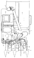
図1及び図2には、本発明を具現化した農業機械であるコンバインが示されている。
走行装置1を有する車台2の前方には、刈取装置6が設けられている。この刈取装置6には、植立穀稈を分草する複数の分草具6aと、植立穀稈を引き起こす複数の引起装置6bと、植立穀稈を刈り取る刈刃6cと、該刈刃6cにて刈り取られた穀稈を挟持して後方に搬送する搬送装置6dが設けられている。この搬送装置6dは刈刃6c後方の株元搬送装置6eと該株元搬送装置6eから搬送されてくる穀稈を引き継いで脱穀装置9に供給する供給搬送装置6fとから構成されている。
1 and 2 show a combine that is an agricultural machine that embodies the present invention.
A cutting device 6 is provided in front of the chassis 2 having the traveling device 1. The mowing device 6 includes a plurality of weeding tools 6a for weeding the planted cereal, a plurality of pulling devices 6b for causing the planted cereal, a cutting blade 6c for mowing the planted cereal, and the cutting blade A transport device 6d is provided for sandwiching and transporting the cereals harvested in 6c to the rear. This transport device 6d is composed of a stock transport device 6e behind the cutting blade 6c and a supply transport device 6f that takes over the cereals transported from the stock transport device 6e and supplies them to the threshing device 9.

前記刈取装置6は、車台2の前部に立設する懸架メタル42の上方に設ける回転軸42aを支点にして上下動する刈取装置支持フレーム60にて、その略左右中間部で支持されている。そして、刈取装置6は操作部3に設けるレバー4を前後方向に傾動させることによって刈取装置支持フレーム60と共に上下動する構成である。   The reaping device 6 is supported by a reaping device support frame 60 that moves up and down about a rotating shaft 42a provided above a suspension metal 42 standing on the front portion of the chassis 2 at its substantially left and right intermediate portions. . The reaping device 6 is configured to move up and down together with the reaping device support frame 60 by tilting the lever 4 provided in the operation unit 3 in the front-rear direction.

車台2の上方には、前記供給搬送装置6fから搬送されてくる穀稈を引き継いで搬送するフィードチェン7を有する脱穀装置9と、該脱穀装置9の右側方であって、この脱穀装置9で脱穀選別された穀粒を一時貯溜するグレンタンク10と、該グレンタンク10の前方に位置していてコンバインの各種操作を実行する操作部3が載置されている。また、車台2の前部には走行装置1を駆動する走行伝動装置13が設けられている。   Above the chassis 2, a threshing device 9 having a feed chain 7 that takes over and transports the cereals conveyed from the supply conveying device 6 f, and a threshing device 9 on the right side of the threshing device 9. A grain tank 10 for temporarily storing the grain that has been threshed and an operation unit 3 that is positioned in front of the grain tank 10 and that performs various operations of the combine are placed. In addition, a traveling transmission device 13 that drives the traveling device 1 is provided at the front portion of the chassis 2.

脱穀装置9の後方には、前記フィードチェン7から搬送されてくる排稈を引き継いで搬送する排稈チェン61と、該排稈チェン61の終端部下方には排稈を切断するカッター装置62が設けられている。また、この実施例のカッター装置62の後方には、排稈を結束するノッター等の他の作業機を装着してもよい。   Behind the threshing device 9 is a waste chain 61 that takes over and transports the waste fed from the feed chain 7, and a cutter device 62 that cuts the waste is disposed below the terminal end of the waste chain 61. Is provided. Moreover, you may mount | wear with other working machines, such as a knotter which binds a waste, behind the cutter apparatus 62 of this Example.

前記グレンタンク10内の穀粒量が満杯となると、縦オーガ11と横オーガ12から穀粒を機外へと排出する。縦オーガ11は電気モータ(図示せず)にて旋回可能に構成され、また、横オーガ12は油圧シリンダ(図示せず)にて昇降可能に構成されている。そして、横オーガ12は縦オーガ11の上部に連結されて一体的に構成され、縦オーガ11が旋回すると、横オーガ12も一緒に旋回する構成となっている。   When the grain amount in the Glen tank 10 is full, the grain is discharged from the vertical auger 11 and the horizontal auger 12 to the outside of the machine. The vertical auger 11 is configured to be turnable by an electric motor (not shown), and the horizontal auger 12 is configured to be movable up and down by a hydraulic cylinder (not shown). The horizontal auger 12 is connected to the upper portion of the vertical auger 11 and is integrally formed. When the vertical auger 11 turns, the horizontal auger 12 also turns together.

また、コンバインは操作部3に設ける副変速レバーを操作して走行伝動装置13内の副変速の位置を決定し、その後、走行変速レバー63を操作してエンジン39からの動力を油圧無段変速装置16及び走行伝動装置13を介して走行装置1の左右のクローラ37L、37Rに伝動して任意の速度で走行する構成である。このように、前記走行変速レバー63の操作量によって速度が変速されるとともに、走行変速レバー63の前方向と後方向の操作によってコンバインが前後進する構成である。   Further, the combine operates a sub-shift lever provided in the operation section 3 to determine the position of the sub-shift in the travel transmission device 13, and then operates the travel shift lever 63 to hydraulically continuously shift the power from the engine 39. In this configuration, the vehicle travels at an arbitrary speed by being transmitted to the left and right crawlers 37L and 37R of the traveling device 1 through the device 16 and the traveling transmission device 13. As described above, the speed is changed by the operation amount of the traveling speed change lever 63, and the combine is moved forward and backward by the forward and rearward operations of the traveling speed change lever 63.

また、コンバインは操作部3に設ける前記レバー4を左右方向に傾倒操作することによって左右方向に旋回する構成であり、さらに、レバー4の左右方向への傾倒操作量によって旋回半径が決定される構成である。   Further, the combine is configured to turn left and right by tilting the lever 4 provided in the operation unit 3 in the left and right direction, and the turning radius is determined by the amount of tilt operation of the lever 4 in the left and right direction. It is.

このようなコンバインを前進させて刈取作業をすると、圃場面に植立している穀稈は、分草具6aにて分草され、その後、引起装置6bにて引き起こされて刈刃6cにて刈り取られる構成である。その後、刈り取られた穀稈は株元搬送装置6eにて後方へ搬送され、供給搬送装置6fへと引き継ぎ搬送される。この供給搬送装置6fに引き継がれた穀稈は、さらに後方へと搬送されて、脱穀装置9のフィードチェン7へと引継ぎ搬送され、穀稈はフィードチェン7で後方へ搬送されながら脱穀装置9にて脱穀選別される構成である。   When the harvesting operation is performed by advancing such a combine, the cereal buds planted in the field scene are weeded by the weeding tool 6a, and then caused by the pulling device 6b and by the cutting blade 6c. It is a structure that is reaped. Thereafter, the harvested corn straw is transported backward by the stock transporter 6e and transferred to the supply transporter 6f. The cereal that has been handed over to the supply / conveyance device 6f is further transported rearward and is handed over to the feed chain 7 of the threshing device 9, while the cereal is transported rearward by the feed chain 7 to the threshing device 9. And threshing and sorting.

このように脱穀選別された穀粒は、一番揚穀筒64からグレンタンク10内へと搬送されて一時貯留され、このグレンタンク10内に貯留される穀粒量が満杯になると、操作部3の報知手段(ブザーや表示装置)でオペレータに報知される構成である。その後、刈取作業を中断して、グレンタンク10内の穀粒を機外へと排出する作業を開始する。コンバインを任意の位置(トラック近傍位置)へと移動させ、横オーガ12をオーガ受け65から離脱させて穀粒排出口12aをトラックの荷台等の位置へ移動させる。そして、操作部3に設けている穀粒排出レバーを入り状態として、グレンタンク10内の穀粒を機外へと排出し、グレンタンク10内の穀粒排出が終了すると、横オーガ12は再びオーガ受け65へと収納されていく構成である。   The grain thus threshed and sorted is transported from the first cereal cylinder 64 into the Glen tank 10 and temporarily stored, and when the amount of the grain stored in the Glen tank 10 is full, the operation unit 3 is a configuration in which the operator is notified by the notification means (buzzer or display device). Thereafter, the cutting operation is interrupted, and the operation for discharging the grains in the Glen tank 10 to the outside of the machine is started. The combine is moved to an arbitrary position (position near the truck), the horizontal auger 12 is detached from the auger receiver 65, and the grain outlet 12a is moved to a position such as a truck bed. Then, the grain discharge lever provided in the operation unit 3 is turned on, the grain in the Glen tank 10 is discharged to the outside of the machine, and when the grain discharge in the Glen tank 10 is finished, the horizontal auger 12 is again The structure is housed in the auger receiver 65.

前記レバー4を左方向に傾動すると、走行伝動装置13の左クラッチが切れて、さらに、左方向へ傾動すると左側ブレーキが作動してコンバインは左旋回し、右方向に傾動させると右クラッチが切れて、さらに、右方向へ傾動すると右側ブレーキが作動してコンバインは右旋回する構成である。   When the lever 4 is tilted to the left, the left clutch of the traveling transmission 13 is disengaged. Further, when the lever 4 is tilted to the left, the left brake is actuated and the combine turns left, and when the tilt is tilted to the right, the right clutch is disengaged. Further, when tilting to the right, the right brake is activated and the combine turns right.

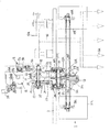
前記走行伝動装置13について、図3に基づいて説明する。
走行伝動装置13には、エンジン39からの動力を入力するプーリ15が設けられている。また、該プーリ15からの動力を受けて変速する油圧無段変速装置16が設置されている。
The travel transmission device 13 will be described with reference to FIG.
The travel transmission device 13 is provided with a pulley 15 for inputting power from the engine 39. In addition, a hydraulic continuously variable transmission 16 that changes the speed by receiving power from the pulley 15 is provided.

走行伝動装置13の上部には、軸17が設けられ、カウンタギヤケ−ス5を介して前記油圧無段変速装置16と接続している。カウンタギヤケ−ス5内には歯車5a、5b、5cが設けられていて、歯車5aは歯車5bと噛み合い、歯車5bは歯車5cと噛み合っていて、動力を減速している構成である。38は油圧無段変速装置16を冷却するファンである。   A shaft 17 is provided in the upper part of the traveling transmission device 13 and is connected to the hydraulic continuously variable transmission 16 through the counter gear case 5. The counter gear case 5 is provided with gears 5a, 5b, and 5c. The gear 5a meshes with the gear 5b, and the gear 5b meshes with the gear 5c to reduce the power. A fan 38 cools the hydraulic continuously variable transmission 16.

軸17には移動体18が左右方向移動自在に遊嵌されている。また、軸17には歯車19が遊嵌している。前記移動体18には、歯車22と歯車21が形成されていて、さらに、移動体18には、前記歯車19に接続する爪部20が形成されている。   A movable body 18 is loosely fitted to the shaft 17 so as to be movable in the left-right direction. A gear 19 is loosely fitted on the shaft 17. A gear 22 and a gear 21 are formed on the moving body 18, and a claw portion 20 connected to the gear 19 is formed on the moving body 18.

軸17の下手側には、軸23が設けられ、該軸23には、歯車22と噛み合う歯車26、歯車21と噛み合う歯車25、歯車19と噛み合う歯車24がそれぞれ固定されている。この構成は副変速機構であり、操作部3に設けている副変速レバー(図示せず)にて、オペレータが圃場の状況等を確認して任意に設定する構成である。さらに、軸23には、歯車27が固定されている。   A shaft 23 is provided on the lower side of the shaft 17, and a gear 26 that meshes with the gear 22, a gear 25 that meshes with the gear 21, and a gear 24 that meshes with the gear 19 are fixed to the shaft 23. This configuration is a sub-transmission mechanism, and is a configuration in which an operator confirms the state of the field and the like with a sub-transmission lever (not shown) provided in the operation unit 3 and arbitrarily sets it. Further, a gear 27 is fixed to the shaft 23.

前記軸23の下手側には、サイドクラッチ軸28が設けられている。該サイドクラッチ軸28の中間部には、前記歯車27と常時噛み合う歯車29が固定していて、その両端部には、ブレーキ30L,30Rが設けられている。さらに、サイドクラッチ軸28には、サイドクラッチ31L,31Rが設けられ、長手方向に移動可能に構成されている。該サイドクラッチ31L,31Rには歯車32L,32Rが構成されていて、圧縮バネ33L,33Rの付勢力にて、共に歯車29方向へ付勢されていて、歯車29の爪部29L,29Rを介して歯車29と噛み合っている構成である。   A side clutch shaft 28 is provided on the lower side of the shaft 23. A gear 29 that always meshes with the gear 27 is fixed to an intermediate portion of the side clutch shaft 28, and brakes 30L and 30R are provided at both ends thereof. Further, the side clutch shaft 28 is provided with side clutches 31L and 31R, and is configured to be movable in the longitudinal direction. The side clutches 31L and 31R are configured with gears 32L and 32R, and both are biased in the direction of the gear 29 by the biasing force of the compression springs 33L and 33R, via the claw portions 29L and 29R of the gear 29. The gear 29 is engaged with the gear 29.

サイドクラッチ軸28の下手側には、走行軸34L,34Rが設けられている。走行軸34L,34Rの一端には歯車35L,35Rが固定していて、歯車32L,32Rと常時噛み合っている。走行軸34L,34Rの他端には、スプロケット36L,36Rが固定していて、該スプロケット36L,36Rにはクローラ37L,37Rが巻き回している構成である。   Traveling shafts 34 </ b> L and 34 </ b> R are provided on the lower side of the side clutch shaft 28. Gears 35L and 35R are fixed to one end of the traveling shafts 34L and 34R, and are always meshed with the gears 32L and 32R. Sprockets 36L and 36R are fixed to the other ends of the traveling shafts 34L and 34R, and crawlers 37L and 37R are wound around the sprockets 36L and 36R.

前述のごとく構成されたコンバインを走行させて刈取作業を実行する作用について説明する。
レバー4を前方へ傾動させて、刈取装置6を下降させ、操作部3の刈取装置6を駆動する刈取レバー(図示せず)と、脱穀装置9を駆動する脱穀レバー(図示せず)を入り状態とする。
The operation of running the harvesting operation by running the combine constructed as described above will be described.
The lever 4 is tilted forward, the mowing device 6 is lowered, and a mowing lever (not shown) for driving the mowing device 6 of the operation unit 3 and a threshing lever (not shown) for driving the threshing device 9 are entered. State.

次に、前述の走行伝動装置13内の副変速機構を任意に設定する。そして、操作部3に設けているHSTレバー40を前進側に傾動させる。すると、油圧無段変速装置16の可変油圧ポンプ16aの斜板が傾斜して、内部の油が定量油圧モータ16bへと送油される。これにより、エンジンからの動力は、カウンタギヤケ−ス5を経由して走行伝動装置13内の軸17が回転し、移動体18が回転する。前記走行用の油圧無段変速装置16の定量油圧モータ16bについては、可変油圧モ−タとすることで、前述した副変速機構が不要となる。   Next, the auxiliary transmission mechanism in the above-described traveling transmission device 13 is arbitrarily set. Then, the HST lever 40 provided in the operation unit 3 is tilted forward. Then, the swash plate of the variable hydraulic pump 16a of the hydraulic continuously variable transmission 16 is tilted, and the internal oil is sent to the fixed hydraulic motor 16b. As a result, the power from the engine rotates the shaft 17 in the travel transmission device 13 via the counter gear case 5 and the moving body 18 rotates. The fixed hydraulic motor 16b of the traveling hydraulic continuously variable transmission 16 is a variable hydraulic motor so that the above-described auxiliary transmission mechanism is not necessary.

前記移動体18の歯車22,21と、軸17に遊嵌している歯車19は副変速部であり、軸23に固着されている歯車26,25,24とそれぞれ噛み合わせて、低速,中速,高速を決定する。これにより、軸23と共に、該軸23に固着している歯車27が回転する。該歯車27の回転力は、歯車29に伝達され、その後、左爪部29L,歯車32L,歯車35Lを介して、左スプロケット36Lを駆動する。右側の伝動系は、その対称であり、歯車29に伝達されている動力は、右爪部29R,歯車32R,歯車35Rを介して、右スプロケット36Rを駆動する。   The gears 22 and 21 of the moving body 18 and the gear 19 loosely fitted to the shaft 17 are sub-transmission parts, which mesh with the gears 26, 25 and 24 fixed to the shaft 23, respectively. Determine the speed and speed. Thereby, together with the shaft 23, the gear 27 fixed to the shaft 23 rotates. The rotational force of the gear 27 is transmitted to the gear 29, and then drives the left sprocket 36L via the left claw portion 29L, the gear 32L, and the gear 35L. The transmission system on the right side is symmetrical, and the power transmitted to the gear 29 drives the right sprocket 36R via the right claw portion 29R, the gear 32R, and the gear 35R.

従って、左右のスプロケット36L,36Rが同じ速度で回転するので、コンバインは前進する。
このように前進走行することにより、圃場の植立穀稈は刈取装置6にて刈り取られ、供給搬送装置8で搬送されながら扱ぎ深さが調節され、さらに後方のフィードチェン7へと引継ぎ搬送されていく。該フィードチェン7にて搬送されながら、脱穀装置9にて脱穀選別されて、穀粒はグレンタンク10内へ一時貯留される。グレンタンク10内の穀粒が所定量(満杯)となると、縦オーガ11,横オーガ12からトラック等の荷台の機外へと排出する。
Therefore, since the left and right sprockets 36L and 36R rotate at the same speed, the combine moves forward.
By traveling forward in this way, the planted cereals in the field are cut by the cutting device 6, the handling depth is adjusted while being transported by the supply and transport device 8, and further transferred to the rear feed chain 7. It will be done. While being conveyed by the feed chain 7, the threshing device 9 performs threshing and sorting, and the grain is temporarily stored in the Glen tank 10. When the grain in the Glen tank 10 reaches a predetermined amount (full), the grain is discharged from the vertical auger 11 and the horizontal auger 12 to the outside of the loading platform such as a truck.

コンバインが圃場の端まで来て、旋回を行なう時は、次のようにする。
左方向へ進路変更する時は、レバー4を左方向へ傾動させる。すると、図示しないシフタにより、左サイドクラッチ31Lは圧縮バネ33Lの付勢力に抗して左方向へ移動して、左爪部29Lが歯車29から離脱する。これにより、左スプロケット36Lへの直進動力は断たれるが、コンバインは少し左方向へ進路変更するだけである。そこで、さらにシフタを左方向へ移動することにより、左サイドクラッチ31Lを左へ移動させて、ディスク形式の左ブレーキ30Lを作動させる。これにより、左スプロケット36Lはロックされるので、コンバインは左方向へ旋回していく。
When the combine comes to the end of the field and turns, do as follows.
When changing the course to the left, the lever 4 is tilted to the left. Then, the left side clutch 31L moves to the left against the urging force of the compression spring 33L by a shifter (not shown), and the left claw portion 29L is detached from the gear 29. As a result, the straight driving power to the left sprocket 36L is cut off, but the combine only changes the course in the left direction. Therefore, by further moving the shifter to the left, the left side clutch 31L is moved to the left, and the disc-type left brake 30L is operated. As a result, the left sprocket 36L is locked, and the combine turns to the left.

右方向への進路変更する時は、レバー4を右方向へ傾動させるが、その作用は前記左方向と対称なので説明は省略する。
一方、刈取装置6と脱穀装置9のフィードチェン7については、脱穀装置9の唐箕(図示せず、又その他どこでもよい)から駆動するように構成する。特に、唐箕から駆動することで、高速回転が必要な油圧無段変速装置41の入力には適している。図4に示すように、脱穀装置9の一部の動力は、油圧無段変速装置41へと入力され、可変ポンプ41aの斜板の角度が変更されて定量油圧モ−タ41bへと送油される。この送油量によって定量油圧モ−タ41bから出力される回転数が変更される。即ち、油圧無段変速装置41は、左側の刈取懸架メタル42に固定して設ける構成としているので、油圧無段変速装置41を取り付けるための専用の部材が不要となる。
When changing the course in the right direction, the lever 4 is tilted in the right direction, but its operation is symmetric with the left direction, and the description thereof is omitted.
On the other hand, the feed chain 7 of the reaping device 6 and the threshing device 9 is configured to be driven from the tang (not shown or anywhere else) of the threshing device 9. In particular, it is suitable for the input of the hydraulic continuously variable transmission 41 that requires high-speed rotation by driving from Karatsu. As shown in FIG. 4, a part of the power of the threshing device 9 is input to the hydraulic continuously variable transmission 41, and the angle of the swash plate of the variable pump 41 a is changed to supply oil to the metering hydraulic motor 41 b. Is done. The number of revolutions output from the fixed hydraulic motor 41b is changed according to the oil supply amount. That is, the hydraulic continuously variable transmission 41 is configured to be fixed to the left-side cutting suspension metal 42, so that a dedicated member for attaching the hydraulic continuously variable transmission 41 is not required.

定量油圧モ−タ41bから出力された動力は、刈取装置6を支持する左右の刈取懸架メタル42のうち左側の刈取懸架メタル42の中を通過するように構成している。そして、左側の刈取懸架メタル42の適宜位置から出力されて、刈取装置6とフィ−ドチェン7を駆動するように構成している。   The power output from the fixed hydraulic motor 41b is configured to pass through the left harvesting suspension metal 42 of the left and right harvesting suspension metals 42 that support the harvesting device 6. Then, it is output from an appropriate position of the left harvesting suspension metal 42 to drive the harvesting device 6 and the feed chain 7.

このように、刈取装置6とフィ−ドチェン7への伝動系を、左側の刈取懸架メタル42内に設ける構成としているので、専用の伝動ケ−スが不要となり廉価に構成可能となる。
具体的には、定量油圧モ−タ41bから出力された動力は、左側の刈取懸架メタル42内の歯車43,44,45で減速され、その後、軸46から出力される。軸46の動力は、ベルトプ−リ47を介して刈取装置6に伝達される。また、このベルトプ−リ47には、刈取装置6のベルトテンションクラッチ48が設けられている。
As described above, the transmission system to the reaping device 6 and the feed chain 7 is provided in the left reaping suspension metal 42, so that a dedicated transmission case is not required and can be configured at low cost.
Specifically, the power output from the fixed hydraulic motor 41 b is decelerated by the gears 43, 44, 45 in the left cutting suspension metal 42 and then output from the shaft 46. The power of the shaft 46 is transmitted to the reaping device 6 via the belt pulley 47. Further, the belt pulley 47 is provided with a belt tension clutch 48 of the reaping device 6.

また、軸46の動力は、ベルトプ−リ49と変速部50を介してフィ−ドチェン7に伝達される。前記ベルトプ−リ49には、フィ−ドチェン7のベルトテンションクラッチ51が設けられている。また、変速部50には、有段変速部が設けられている。この有段変速部については、シフタによる複数段の変速であるが、本実施例では、2段変速としている。   The power of the shaft 46 is transmitted to the feed chain 7 via the belt pulley 49 and the transmission unit 50. The belt pulley 49 is provided with a belt tension clutch 51 of the feed chain 7. The transmission unit 50 is provided with a stepped transmission unit. The stepped transmission unit is a multi-stage shift using a shifter. In the present embodiment, a two-stage shift is used.

54は脱穀装置9全体の伝動を入り切りする脱穀のベルトテンションクラッチである。このベルトテンションクラッチ54が入りでないと、前記フィ−ドチェン7のベルトテンションクラッチ51を入りとしてもフィ−ドチェン7が駆動されないので安全である。   Reference numeral 54 denotes a threshing belt tension clutch that turns on and off the transmission of the entire threshing device 9. If the belt tension clutch 54 is not engaged, the feed chain 7 will not be driven even if the belt tension clutch 51 of the feed chain 7 is engaged, which is safe.

前記油圧無段変速装置41の可変ポンプ41aの斜板が傾斜しており、定量油圧モ−タ41bから回転駆動力が出力されていても、前記ベルトテンションクラッチ48を切りにすると、刈取装置6の駆動は停止される。また、ベルトテンションクラッチ51を切りにすると、フィ−ドチェン7の駆動は停止される。このように、油圧無段変速装置41及び刈取装置6とフィードチェン7のクラッチ部でも、刈取装置6とフィードチェン7の駆動をそれぞれ停止できるので、二重の安全機構となる。   Even if the swash plate of the variable pump 41a of the hydraulic continuously variable transmission 41 is inclined and the rotational driving force is output from the fixed hydraulic motor 41b, if the belt tension clutch 48 is disengaged, the cutting device 6 Is stopped. When the belt tension clutch 51 is turned off, the drive of the feed chain 7 is stopped. As described above, the hydraulic continuously variable transmission 41 and the clutch portion of the reaping device 6 and the feed chain 7 can also stop the driving of the reaping device 6 and the feed chain 7, respectively, thus providing a double safety mechanism.

前記油圧無段変速装置41内にはリリーフバルブ41cを設けているので、刈取装置6やフィードチェン7に詰まりが発生すると、リリーフバルブ41cが作動して破損を帽子できるようになる。もちろん、前記リリーフバルブ41cの出力トルク規制は、刈取装置6とフィードチェン7の詰まり状態に適した値としている。   Since the relief valve 41c is provided in the hydraulic continuously variable transmission 41, when the reaping device 6 or the feed chain 7 is clogged, the relief valve 41c is actuated so that damage can be blocked. Of course, the output torque regulation of the relief valve 41 c is set to a value suitable for the clogging state of the cutting device 6 and the feed chain 7.

従来においては、走行伝動装置13から刈取装置6やフィードチェン7を駆動していたので、走行伝動装置13を駆動するための油圧無段変速装置16の出力トルク規制値で刈取装置6やフィードチェン7の駆動が停止されていたので、過大な負荷が作用した場合には、刈取装置6やフィードチェン7が破損するということがあったが、このような不具合を防止できるようになる。   Conventionally, the reaping device 6 and the feed chain 7 are driven from the traveling transmission device 13, and therefore the reaping device 6 and the feed chain are controlled by the output torque regulation value of the hydraulic continuously variable transmission 16 for driving the traveling transmission device 13. Since the drive of 7 is stopped, when an excessive load is applied, the reaping device 6 and the feed chain 7 may be damaged. However, such a problem can be prevented.

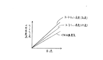
図5には、コンバインの車速に対する刈取装置6とフィードチェン7の駆動速度の関係を示している。刈取装置6とフィードチェン7の駆動速度の可変は、前述のごとく一つの油圧無段変速装置41で行う構成である。   FIG. 5 shows the relationship between the cutting speed of the harvesting device 6 and the feed chain 7 with respect to the combine vehicle speed. The drive speed of the reaping device 6 and the feed chain 7 can be varied by one hydraulic continuously variable transmission 41 as described above.

このため、倒伏時や湿材時においては、刈取装置6の駆動速度を油圧無段変速装置41で減速させると、フィードチェン7の駆動速度も減速してしまう。この場合においては、脱穀装置9を通過する穀稈の速度が遅くなるために、藁屑の発生が多くなってロスが多くなるという不具合が起きてしまう。そこで、フィードチェン7については、前記変速部50で変速して、フィードチェン7を高速で駆動させるようにする。具体的には、レバー50aを操作してシフタ50bをチェンジして高速歯車50dに噛み合わせるようにする。50cは低速歯車である。   For this reason, when the driving speed of the mowing device 6 is decelerated by the hydraulic continuously variable transmission 41 at the time of lodging or wet material, the driving speed of the feed chain 7 is also decelerated. In this case, since the speed of the culm passing through the threshing device 9 is slow, the problem that the generation of swarf increases and the loss increases occurs. Therefore, the feed chain 7 is shifted by the transmission unit 50 to drive the feed chain 7 at a high speed. Specifically, the lever 50a is operated to change the shifter 50b so as to mesh with the high speed gear 50d. 50c is a low speed gear.

このように、刈取装置6への伝動系と分岐後において、フィードチェン7を変速する専用の変速部50を設けるように構成したので、廉価な構成となる。
前記油圧無段変速装置41から出力後の伝動系については、図6に示すように左側のクローラ37Lの上方に配置するように構成している。これにより、伝動系に落下する藁屑は、クローラ37L上に落下し、絶えずクローラ37Lで圃場上に搬送されるので、藁屑が堆積するのを防止できるようになる。
In this way, since the dedicated transmission unit 50 for shifting the feed chain 7 is provided after the transmission system to the reaping device 6 and branching, the configuration is inexpensive.
The transmission system output from the hydraulic continuously variable transmission 41 is configured to be disposed above the left crawler 37L as shown in FIG. As a result, the waste falling on the transmission system falls on the crawler 37L and is continuously conveyed onto the field by the crawler 37L, so that it is possible to prevent the waste from accumulating.

前記刈取装置6は、図7に示すように、回動支点52を軸芯として左側方へ回動可能に構成している。そして、刈取装置6を側方へ回動させる際には、刈取装置6を動力を伝達するベルト47aが緩む方向に構成している。これにより、刈取装置6を左方向へ回動させるときには、刈取装置6への伝動ベルト47aを外すことなく刈取装置6の左側方向への回動が可能となる。   As shown in FIG. 7, the reaping device 6 is configured to be rotatable leftward about a rotation fulcrum 52 as an axis. When the reaping device 6 is rotated to the side, the reaping device 6 is configured in such a direction that the belt 47a for transmitting power is loosened. Thus, when the reaping device 6 is rotated in the left direction, the reaping device 6 can be rotated in the left direction without removing the transmission belt 47a to the reaping device 6.

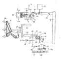
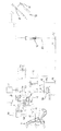
図8に示すように、脱穀装置9へ入力された動力は、プーリ66aから唐箕66を駆動する。この唐箕66からプーリ68、ベルト69、プーリ70、軸71を介して、油圧無段変速装置41へ入力される構成である。一方、この実施例の脱穀装置9においては、唐箕66の前方上方に第二唐箕67を設ける構成としている。この第二唐箕67の回転動力は、前記油圧無段変速装置41で変速後の、軸46、プーリ72、ベルト73、プーリ74、軸75を介して駆動するように構成している。これにより、第二唐箕67の駆動が容易になる。また、第二唐箕67は油圧無段変速装置41で変速されるので、フィードチェン7と同調して変速されることになり、コンバインの車速に応じた選別風を起風できて選別性能の向上を図ることができるようになる。   As shown in FIG. 8, the motive power input to the threshing device 9 drives the red pepper 66 from the pulley 66a. In this configuration, an input is made to the hydraulic continuously variable transmission 41 from the tang 66 through a pulley 68, a belt 69, a pulley 70, and a shaft 71. On the other hand, in the threshing device 9 of this embodiment, a second Chinese potato 67 is provided in front of the Chinese potato 66. The rotational power of the second tang 67 is configured to be driven via the shaft 46, the pulley 72, the belt 73, the pulley 74, and the shaft 75 after being shifted by the hydraulic continuously variable transmission 41. This facilitates the driving of the second tang 67. Further, since the second tang 67 is shifted by the hydraulic continuously variable transmission 41, the gear is shifted in synchronism with the feed chain 7, and the sorting wind corresponding to the combine vehicle speed can be generated to improve the sorting performance. Can be planned.

76は脱穀装置9の一番ラセンと二番ラセンとの間にある第三唐箕である。この第三唐箕76は、前記第二唐箕67を駆動する軸75に設けているプーリ77、ベルト78、プーリ79、軸80を介して駆動するように構成している。これにより、第三唐箕76の伝動系が廉価に構成可能となる。また、第三唐箕76は油圧無段変速装置41で変速されるので、フィードチェン7と同調して変速されることになり、コンバインの車速に応じた選別風を起風できて選別性能の向上を図ることができるようになる。(図9)また、第三唐箕76よりも、第二唐箕67の駆動速度を速く構成している。   Reference numeral 76 is a third tang between the first and second spirals of the threshing device 9. The third tang 76 is configured to be driven through a pulley 77, a belt 78, a pulley 79, and a shaft 80 provided on a shaft 75 that drives the second tang 67. As a result, the transmission system of the third tang 76 can be configured at low cost. Further, since the third carton 76 is shifted by the hydraulic continuously variable transmission 41, the gear is shifted in synchronism with the feed chain 7, and the sorting wind according to the combine vehicle speed can be generated to improve the sorting performance. Can be planned. (FIG. 9) Moreover, the driving speed of the second tang 67 is faster than that of the third tang 76.

コンバインが後進する場合においては、前記油圧無段変速装置41の可変油圧ポンプ41aの斜板を中立にして、定量油圧モータ41bからの出力を停止する。これにより、コンバインが後進を開始すると、刈取装置6、フィードチェン7、第二唐箕67、第三唐箕76の回転が停止する。コンバインが後進する最には、脱穀装置9内の被選別物量は少なくなるので、前記第二唐箕67、第三唐箕76の回転を止めることで、選別のしすぎを抑制し、三番飛散を防止できるようになる。   When the combine moves backward, the swash plate of the variable hydraulic pump 41a of the hydraulic continuously variable transmission 41 is made neutral, and the output from the fixed hydraulic motor 41b is stopped. As a result, when the combine starts to reverse, rotation of the cutting device 6, the feed chain 7, the second tang 67, and the third tang 76 stops. When the combine moves backward, the amount of items to be sorted in the threshing device 9 is reduced. Therefore, by stopping the rotation of the second Kara 67 and the third Kara 76, excessive sorting is suppressed, and third scattering is prevented. Can be prevented.

図8に示す61は、前述した排稈チェン61である。また、81は排稈の穂先を搬送する穂先搬送ラグを駆動する穂先チェンである。この排稈チェン61と穂先チェン81(排稈搬送装置92)は、前述した第三唐箕76から駆動するように構成する。即ち、刈取装置6、フィードチェン7、排稈チェン61及び穂先チェン81については、単一の油圧無段変速装置41で駆動する構成である。これにより、刈取装置6から排稈チェン61及び穂先チェン81までの搬送系が同調回転するので、搬送が安定するようになる。また、単一の油圧無段変速装置41で駆動するので、廉価な構成となる。   The reference numeral 61 shown in FIG. Reference numeral 81 denotes a tip chain that drives a tip transport lug that transports the waste tip. The waste chain 61 and the tip chain 81 (a waste transporting device 92) are configured to be driven from the above-mentioned third hot pot 76. That is, the cutting device 6, the feed chain 7, the waste chain 61, and the tip chain 81 are configured to be driven by a single hydraulic continuously variable transmission 41. Thereby, since the conveyance system from the cutting device 6 to the waste chain 61 and the tip chain 81 rotates synchronously, the conveyance becomes stable. Moreover, since it drives with the single hydraulic continuously variable transmission 41, it becomes an inexpensive structure.

また、ライン82は、脱穀装置9の右側の端部を示している。そして、排稈チェン61と穂先チェン81は、脱穀装置9の右側から駆動する構成としているので、伝動が容易となる。特に、搬送される排藁の影響を受けなくなるので、伝動が安定し、搬送される排藁も安定して搬送されるようになる。   Moreover, the line 82 has shown the right edge part of the threshing apparatus 9. FIG. And since the waste chain 61 and the tip chain 81 are set as the structure driven from the right side of the threshing apparatus 9, transmission becomes easy. In particular, since it is not affected by the waste that is transported, the transmission is stable, and the waste that is transported is also transported stably.

また、コンバインの車速がゼロとなりコンバインが停車した状態においては、前記油圧無段変速装置41からの出力回転を停止させて、前記刈取装置6から排稈チェン61及び穂先チェン81までの搬送系の駆動回転も停止させるようにする。これにより、搬送される穀稈も停止するので、稈こぼれ等が防止できて搬送が安定するようになる。   Further, when the combine vehicle speed is zero and the combine is stopped, the output rotation from the hydraulic continuously variable transmission 41 is stopped and the conveying system from the reaping device 6 to the waste chain 61 and the tip chain 81 is stopped. The drive rotation is also stopped. As a result, the transported cereal meal is also stopped, so that spillage or the like can be prevented and the transportation becomes stable.

また、前記刈取装置6から排稈チェン61及び穂先チェン81までの搬送系に加えて、前述した第二唐箕67、第三唐箕76についても、単一の油圧無段変速装置41から駆動されるので、廉価な構成になると共に伝動系が簡素になる。   Further, in addition to the conveying system from the cutting device 6 to the waste chain 61 and the tip chain 81, the above-described second tang 67 and third tang 76 are driven from a single hydraulic continuously variable transmission 41. Therefore, it becomes an inexpensive structure and the transmission system is simplified.

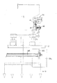
図10に示す油圧無段変速装置41については、走行伝動装置13に取り付ける構成としている。そして、走行伝動装置13を無段変速する油圧無段変速装置16の可変油圧ポンプ16aから前記油圧無段変速装置41を駆動する構成としている。具体的には、油圧無段変速装置16の可変油圧ポンプ16aから軸83を介して油圧無段変速装置41の可変油圧ポンプ41aを駆動する構成である。   The hydraulic continuously variable transmission 41 shown in FIG. 10 is configured to be attached to the traveling transmission device 13. The hydraulic continuously variable transmission 41 is driven from the variable hydraulic pump 16a of the hydraulic continuously variable transmission 16 that continuously changes the travel transmission device 13. Specifically, the variable hydraulic pump 41 a of the hydraulic continuously variable transmission 41 is driven from the variable hydraulic pump 16 a of the hydraulic continuously variable transmission 16 via the shaft 83.

そして、油圧無段変速装置41の定量油圧モータ41bから出力された動力は、変速部84で変速され、その後、刈取クラッチ48を介して刈取装置6が駆動される構成である。また、フィードチェンクラッチ51を介してフィードチェン7が駆動される構成である。前記フィードチェンクラッチ51とフィードチェン7との間には軸85を設けているが、この軸85から、プーリ86、ベルト87、プーリ88、軸67aを介して第二唐箕67を駆動する構成である。66の唐箕については、エンジン39から脱穀クラッチ54を介して駆動される構成である。54aのプーリからは、脱穀装置9内の扱胴、処理胴、選別部を駆動する構成である。   The power output from the fixed hydraulic motor 41 b of the hydraulic continuously variable transmission 41 is shifted by the transmission unit 84, and then the reaping device 6 is driven via the reaping clutch 48. Further, the feed chain 7 is driven via the feed chain clutch 51. A shaft 85 is provided between the feed chain clutch 51 and the feed chain 7, and the second tongue 67 is driven from the shaft 85 via a pulley 86, a belt 87, a pulley 88, and a shaft 67a. is there. 66 is driven by the engine 39 via the threshing clutch 54. From the pulley of 54a, it is the structure which drives the handling cylinder in the threshing apparatus 9, a processing cylinder, and the selection part.

前記第二唐箕67を駆動する軸67aにはプーリ89が設けられ、このプーリ89からベルト90、プーリ91、軸76bを介して第三唐箕76を駆動する構成としている。
前述のごとく、油圧無段変速装置41は、走行伝動装置13に設ける構成としているので、走行伝動装置13を駆動するための油圧無段変速装置16の近傍に配置されることになり、コンパクトな構成となる。また、油圧無段変速装置41を駆動するための伝動系が簡素になる。また、冷却ファン38によって、油圧無段変速装置16と油圧無段変速装置41の両方を冷却できるので、効率が良くなる。
A pulley 89 is provided on the shaft 67a for driving the second rod 67, and the third rod 76 is driven from the pulley 89 through a belt 90, a pulley 91, and a shaft 76b.
As described above, since the hydraulic continuously variable transmission 41 is configured to be provided in the traveling transmission device 13, the hydraulic continuously variable transmission 41 is disposed in the vicinity of the hydraulic continuously variable transmission 16 for driving the traveling transmission device 13. It becomes composition. Further, the transmission system for driving the hydraulic continuously variable transmission 41 is simplified. Further, since both the hydraulic continuously variable transmission 16 and the hydraulic continuously variable transmission 41 can be cooled by the cooling fan 38, the efficiency is improved.

前記操作部3にはグレンタンク10内の穀粒を排出する排出レバーを設けているが、この排出レバーを入り状態にしてグレンタンク10内の穀粒を排出する際においては、前記走行伝動装置13を変速する油圧無段変速装置16からの出力を停止するようにする。具体的には、可変油圧ポンプ16aの斜板にモータを設けておいて、このモータを制御して斜板を中立状態となるようにする。これにより、穀粒排出時においてはコンバインは走行しないので、排出オーガが移動するのを防止できるようになり、穀粒のこぼれを防止できるようになる。   The operation unit 3 is provided with a discharge lever that discharges the grain in the grain tank 10. When the grain is discharged in the grain tank 10 with the discharge lever in the on state, the traveling transmission device is provided. The output from the hydraulic continuously variable transmission 16 that changes the speed of the gear 13 is stopped. Specifically, a motor is provided on the swash plate of the variable hydraulic pump 16a, and this motor is controlled so that the swash plate is in a neutral state. Thereby, since the combine does not run at the time of grain discharge, it becomes possible to prevent the discharge auger from moving and to prevent spilling of the grain.

また、前記可変油圧ポンプ16aの斜板を制御するモータにポジションセンサを設け、このポジションセンサの値を検出してフィードバックすることで、斜板が中立状態から外れるようとしても、斜板は中立状態に戻るので、穀粒排出時におけるコンバインの走行を防止できるようになる。   Further, a position sensor is provided in a motor that controls the swash plate of the variable hydraulic pump 16a, and even if the swash plate is out of the neutral state by detecting and feeding back the value of the position sensor, the swash plate is in the neutral state. Therefore, it becomes possible to prevent the combine from traveling when the grain is discharged.

また、コンバインが走行している場合は、前記排出レバーを入り状態にしても、穀粒排出を行わないようにしてもよい。   Further, when the combine is traveling, the grain discharge may not be performed even if the discharge lever is in the on state.

コンバインの左側面図Combine left side view コンバインの平面図Top view of the combine 正面の一部の断面図Partial sectional view of the front 伝動線図Transmission diagram 車速と刈取装置速、フィードチェン速との関係図Relationship diagram between vehicle speed, mowing device speed, and feed chain speed 正面の一部の断面図Partial sectional view of the front 伝動線図Transmission diagram 伝動線図Transmission diagram 車速と第二唐箕速、第三唐箕速との関係図Relationship diagram between vehicle speed, 2nd speed, 3rd speed 伝動線図Transmission diagram

符号の説明Explanation of symbols

1 走行装置
2 車台
3 操作部
6 刈取装置
7 フィードチェン
9 脱穀装置
10 グレンタンク
41 油圧無段変速装置
41c リリーフバルブ
48 刈取クラッチ
51 フィードチェンクラッチ
92 排稈搬送装置
DESCRIPTION OF SYMBOLS 1 Traveling device 2 Chassis 3 Operation part 6 Cutting device 7 Feed chain 9 Threshing device 10 Glen tank 41 Hydraulic continuously variable transmission 41c Relief valve 48 Cutting clutch 51 Feed chain clutch 92 Exhaust conveyance device

Claims (3)

走行装置(1)を有する車台(2)上の一側に脱穀装置(9)を設け、該脱穀装置(9)の他側には該脱穀装置(9)で脱穀選別した穀粒を一時貯留するグレンタンク(10)を設け、前記車台(2)の前方には植立穀稈を刈り取って後方の脱穀装置(9)へ向けて搬送する刈取装置(6)を設け、前記グレンタンク(10)の前方にコンバインの運転操作をする操作部(3)を設けたコンバインにおいて、前記刈取装置(6)と脱穀装置(9)のフィードチェン(7)及び該フィードチェン(7)の搬送下手側の排稈搬送装置(92)の駆動は、単一の油圧無段変速装置(41)で駆動するように構成したことを特徴とするコンバイン。   A threshing device (9) is provided on one side of the chassis (2) having the traveling device (1), and the grains threshed and selected by the threshing device (9) are temporarily stored on the other side of the threshing device (9). A grain tank (10) is provided, and a reaping device (6) is provided in front of the chassis (2) to harvest the planted cereal and transport it toward the rear threshing device (9). In the combine provided with an operation unit (3) for operating the combine in front of the feed chain (7) of the reaping device (6) and the threshing device (9) and the lower transfer side of the feed chain (7) The squeeze conveyor device (92) is driven by a single hydraulic continuously variable transmission (41). 前記油圧無段変速装置(41)の動力伝達方向下手側には、刈取装置(6)の伝動を入り切りする刈取クラッチ(48)を設けると共に、脱穀装置(9)のフィードチェン(7)の伝動を入り切りするフィードチェンクラッチ(51)を設けたことを特徴とする請求項1に記載のコンバイン。   On the lower side of the hydraulic continuously variable transmission (41) in the power transmission direction, a cutting clutch (48) for turning on and off the transmission of the cutting device (6) is provided and the transmission of the feed chain (7) of the threshing device (9). The combine according to claim 1, further comprising a feed chain clutch (51) for turning on and off. 前記油圧無段変速装置(41)内には、リリーフバルブ(41c)を設けたことを特徴とする請求項1又は請求項2に記載のコンバイン。   The combine according to claim 1 or 2, wherein a relief valve (41c) is provided in the hydraulic continuously variable transmission (41).
JP2005375421A 2005-12-27 2005-12-27 Combine harvester Pending JP2007174941A (en)

Priority Applications (1)

Application Number Priority Date Filing Date Title
JP2005375421A JP2007174941A (en) 2005-12-27 2005-12-27 Combine harvester

Applications Claiming Priority (1)

Application Number Priority Date Filing Date Title
JP2005375421A JP2007174941A (en) 2005-12-27 2005-12-27 Combine harvester

Publications (2)

Publication Number Publication Date
JP2007174941A true JP2007174941A (en) 2007-07-12
JP2007174941A5 JP2007174941A5 (en) 2008-04-17

Family

ID=38300760

Family Applications (1)

Application Number Title Priority Date Filing Date
JP2005375421A Pending JP2007174941A (en) 2005-12-27 2005-12-27 Combine harvester

Country Status (1)

Country Link
JP (1) JP2007174941A (en)

Cited By (3)

* Cited by examiner, † Cited by third party
Publication number Priority date Publication date Assignee Title
JP2008072991A (en) * 2006-09-22 2008-04-03 Kubota Corp Reaping implement
JP2014027882A (en) * 2012-07-31 2014-02-13 Iseki & Co Ltd Combine harvester
JP2015186447A (en) * 2014-03-26 2015-10-29 株式会社クボタ Combine harvester

Similar Documents

Publication Publication Date Title
JP3859570B2 (en) Combine
JP4882373B2 (en) Combine
JP6666086B2 (en) Combine
JP2006296441A (en) Combine harvester
JP2007174941A (en) Combine harvester
JP2007174941A5 (en)
JP2011130671A (en) Combine harvester
JP5067855B2 (en) Harvesting machine
WO2015198888A1 (en) Combine harvester
JP2009022203A (en) Combine harvester
JP5355241B2 (en) Traveling vehicle
JP5448504B2 (en) Combine
JP5057575B2 (en) Harvesting machine
JP2009112265A (en) Harvester
JP2005160360A (en) Transmission appaartus for combine harvester
JP4720461B2 (en) Combine
JP5998678B2 (en) Combine
JP5532452B2 (en) Combine
JP5319106B2 (en) Combine
JP5166885B2 (en) Combine
JP2010187575A (en) Combine harvester
JP2011167094A (en) Combine harvester
JP5448869B2 (en) Combine
JP2007174971A (en) Working vehicle
JP4453265B2 (en) Combine

Legal Events

Date Code Title Description
A521 Written amendment

Effective date: 20080229

Free format text: JAPANESE INTERMEDIATE CODE: A523