JP2006296441A - Combine harvester - Google Patents

Combine harvester Download PDF

Info

Publication number
JP2006296441A
JP2006296441A JP2006220394A JP2006220394A JP2006296441A JP 2006296441 A JP2006296441 A JP 2006296441A JP 2006220394 A JP2006220394 A JP 2006220394A JP 2006220394 A JP2006220394 A JP 2006220394A JP 2006296441 A JP2006296441 A JP 2006296441A
Authority
JP
Japan
Prior art keywords
cutting
power
shaft
reverse
rotation
Prior art date
Legal status (The legal status is an assumption and is not a legal conclusion. Google has not performed a legal analysis and makes no representation as to the accuracy of the status listed.)
Pending
Application number
JP2006220394A
Other languages
Japanese (ja)
Inventor
Atsushi Terajima
淳 寺島
Current Assignee (The listed assignees may be inaccurate. Google has not performed a legal analysis and makes no representation or warranty as to the accuracy of the list.)
Yanmar Co Ltd
Original Assignee
Yanmar Agricultural Equipment Co Ltd
Priority date (The priority date is an assumption and is not a legal conclusion. Google has not performed a legal analysis and makes no representation as to the accuracy of the date listed.)
Filing date
Publication date
Application filed by Yanmar Agricultural Equipment Co Ltd filed Critical Yanmar Agricultural Equipment Co Ltd
Priority to JP2006220394A priority Critical patent/JP2006296441A/en
Publication of JP2006296441A publication Critical patent/JP2006296441A/en
Pending legal-status Critical Current

Links

Images

Abstract

<P>PROBLEM TO BE SOLVED: To provide a combine harvester solving the problems of grain culms causing conveying blockage at a confluent part of two or more flows of the reaped grain culms to prevent the smooth conveyance to a threshing part side and to reduce the conveying efficiency, that is threshing efficiency, also solving the problems wherein the damage or the like of the constituent members of an upper conveyance structure and a lower conveyance structure are caused at the position having the conveying blockage by a partial large load acting on the constituent members of the upper conveyance structure and the lower conveyance structure, and capable of efficiently removing the conveying blockage of the grain culms. <P>SOLUTION: A power-exchanging mechanism for exchanging the normal rotation/reverse rotation of the power for the reaping part 3 is installed between the output shaft of an engine 35 and the reaping part 3 in the combine harvester having the reaping part 3 for reaping the grain culms and conveying the reaped grain culms to the threshing part 4 side. <P>COPYRIGHT: (C)2007,JPO&INPIT

Description

本発明は、コンバインの構造に関する。より詳しくは、コンバインの刈取部への動力伝達機構において、動力の正転・逆転の切替を行なう切替機構に関する。   The present invention relates to a combine structure. More specifically, the present invention relates to a switching mechanism for switching between normal rotation and reverse rotation of power in a power transmission mechanism to a harvesting unit of a combine.

従来、コンバインの刈取部の一形態として、複数条の穀稈を引起し、挟持搬送しながら刈り取る刈刃装置と、該刈刃装置により刈り取った穀稈を脱穀部側へ搬送する上部搬送機構・下部搬送機構・縦搬送機構とを具備し、上部搬送機構・下部搬送機構の後部では、刈り取った複数条の穀稈を合流部にて一旦合流させ、合流させた穀稈を脱穀部側へ搬送するようにしたものがある。(例えば、特許文献1参照)
特開2000−102311号公報
Conventionally, as one form of a combine harvesting unit, a cutting blade device that raises a plurality of grains and harvests them while holding and conveying, and an upper conveyance mechanism that conveys the grains harvested by the cutting blade device to the threshing unit side It is equipped with a lower transfer mechanism and a vertical transfer mechanism, and at the rear of the upper transfer mechanism and the lower transfer mechanism, the harvested multiple grains are once merged at the merge section, and the merged grains are conveyed to the threshing section side. There is something to do. (For example, see Patent Document 1)
JP 2000-102311 A

しかし、従来のコンバインでは、刈り取った複数条の穀稈の合流部において、穀稈が搬送詰まりを起こして、円滑に脱穀部側へ搬送されず、搬送効率、さらには脱穀効率が低下するという不具合があった。しかも、搬送詰まりを起こした個所においては、上部搬送機構・下部搬送機構の構成部材に部分的に大きな負荷が作用して、該上部搬送機構・下部搬送機構の構成部材を損傷等させるという問題もあった。また、上部搬送機構や下部搬送機構や縦搬送機構等で穀稈が詰まった状態から穀稈を除去するには、穀稈を引き抜いたり、詰まり部分で切断したりしないと除去できず、大きな力を必要とし、手間がかかっていたのである。そこで、本発明では、穀稈の搬送詰まりを効率よく除去できるコンバインを提供する。   However, in the conventional combine, in the joining part of the multiple shed grains, the grains are clogged and are not smoothly conveyed to the threshing part, and the conveyance efficiency and further the threshing efficiency are reduced. was there. In addition, there is a problem in that a part of the upper transport mechanism / lower transport mechanism is partially subjected to a large load at the location where the transport jam occurs, causing damage to the upper transport mechanism / lower transport mechanism. there were. In addition, in order to remove cereals from a state where the cereals are clogged by the upper transport mechanism, the lower transporting mechanism, the vertical transporting mechanism, etc., the cereals cannot be removed unless they are pulled out or cut at the clogged part. It was necessary and time-consuming. Therefore, in the present invention, a combine that can efficiently remove the transport clog of the cereals is provided.

本発明の解決しようとする課題は以上の如くであり、次にこの課題を解決するための手段を説明する。   The problem to be solved by the present invention is as described above. Next, means for solving the problem will be described.

穀稈を刈り取り、脱穀部側へ搬送する刈取部を有するコンバインにおいて、エンジン出力軸と刈取部との間に、刈取部の動力の正転・逆転を切り替える動力切替機構を設けたものである。   In a combine having a harvesting unit that harvests cereal and conveys it to the threshing unit side, a power switching mechanism is provided between the engine output shaft and the harvesting unit to switch between normal rotation and reverse rotation of the power of the harvesting unit.

本発明は、以上のように構成したので、以下に示すような効果を奏する。
穀稈を刈り取り、脱穀部側へ搬送する刈取部を有するコンバインにおいて、エンジン出力軸と刈取部との間に、刈取部の動力の正転・逆転を切り替える動力切替機構を設けたので、刈取部の詰まりが発生した時、刈取部への動力を逆転させることで、容易に詰まりを除去することができる。
従来のコンバインでは、刈り取った複数条の穀稈の合流部において、穀稈が搬送詰まりを起こして、円滑に脱穀部側へ搬送されず、搬送効率、さらには脱穀効率が低下するという不具合があった。
しかも、搬送詰まりを起こした個所においては、上部搬送機構・下部搬送機構の構成部材に部分的に大きな負荷が作用して、該上部搬送機構・下部搬送機構の構成部材を損傷等させるという問題もあった。
また、上部搬送機構や下部搬送機構や縦搬送機構等で穀稈が詰まった状態から穀稈を除去するには、穀稈を引き抜いたり、詰まり部分で切断したりしないと除去できず、大きな力を必要とし、手間がかかっていたのである。
このような不具合を解消することが出来たものである。
Since the present invention is configured as described above, the following effects can be obtained.
In a combine that has a harvesting unit that harvests cereal and transports it to the threshing unit, a power switching mechanism that switches between normal rotation and reverse rotation of the harvesting unit is provided between the engine output shaft and the harvesting unit. When clogging occurs, the clogging can be easily removed by reversing the power to the cutting unit.
In the conventional combine, there is a problem in that the cereal grains are clogged in the merging part of the plurality of harvested cereal grains and are not smoothly conveyed to the threshing part side, and the conveyance efficiency and further the threshing efficiency are reduced. It was.
In addition, there is a problem in that a part of the upper transport mechanism / lower transport mechanism is partially subjected to a large load at the location where the transport jam occurs, causing damage to the upper transport mechanism / lower transport mechanism. there were.
In addition, in order to remove cereals from a state where the cereals are clogged by the upper transport mechanism, the lower transport mechanism, the vertical transporting mechanism, etc. It was necessary and time-consuming.
Such a problem could be solved.

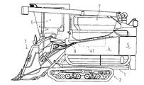
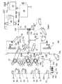
次に、発明の実施の形態を説明する。図1は本発明の一実施例に係るコンバインの全体的な構成を示した側面図、図2は同じく平面図、図3は刈取部の側面図、図4は第一実施例の動力伝達構成概要を示すスケルトン図、図5は副変速レバーを示す図、図6は第二実施例の動力伝達構成概要を示すスケルトン図、図7は刈取クラッチレバーを示す図、図8は第三実施例の動力伝達構成概要を示すスケルトン図、図9はベベルケースを示す断面図、図10は刈取部の動力伝達構成概要を示すスケルトン図、図11はワンウエイユニットを有するスプロケットを示す図、図12は引起し駆動機構を示す図である。   Next, embodiments of the invention will be described. 1 is a side view showing the overall configuration of a combine according to an embodiment of the present invention, FIG. 2 is a plan view of the same, FIG. 3 is a side view of a cutting unit, and FIG. 4 is a power transmission configuration of the first embodiment. FIG. 5 is a diagram showing the auxiliary transmission lever, FIG. 6 is a skeleton diagram showing the outline of the power transmission configuration of the second embodiment, FIG. 7 is a diagram showing the cutting clutch lever, and FIG. 8 is the third embodiment. FIG. 9 is a sectional view showing the bevel case, FIG. 10 is a skeleton diagram showing the outline of the power transmission configuration of the cutting part, FIG. 11 is a diagram showing a sprocket having a one-way unit, and FIG. It is a figure which shows a raising drive mechanism.

始めに、コンバインの全体概略構成について説明する。図1及び図2に示す如く、機体フレーム1の下方に左右一対のクローラ式の走行部2・2を設け、機体フレーム1の左側前端部に刈取部3を取付け、該刈取部3の直後方位置に脱穀部4を設け、該脱穀部4の直後方位置に排藁処理部5を設ける一方、機体フレーム1の右側前部に運転部6を設け、該運転部6の直後方位置に穀粒貯溜タンク7を設けている。8は、脱穀部4の左側部に設けたフィードチェーンである。   First, the overall schematic configuration of the combine will be described. As shown in FIGS. 1 and 2, a pair of left and right crawler type traveling units 2, 2 are provided below the body frame 1, and a cutting part 3 is attached to the left front end of the body frame 1, immediately after the cutting part 3. A threshing unit 4 is provided at a position, and a sewage treatment unit 5 is provided immediately after the threshing unit 4, while a driving unit 6 is provided at the front right side of the machine body frame 1, and a grain is placed immediately after the driving unit 6. A grain storage tank 7 is provided. 8 is a feed chain provided on the left side of the threshing section 4.

次に、コンバインの刈取部3の構成について説明する。前記刈取部3の各搬送機構を支持する刈取フレーム11の構成より説明する。図3に示す如く、刈取フレーム11後部に回動基部12が設けられ、該回動基部12は筒状のフレームで構成して、機体フレーム1前部上に左右一対の支柱10・10を立設して、その上端間に回動基部12が枢支され、内部に刈取入力軸72(図10)が軸支され、エンジン00(図10)からの動力がベルトやプーリ等を介して入力されている。   Next, the structure of the combine harvester 3 will be described. The configuration of the cutting frame 11 that supports each conveyance mechanism of the cutting unit 3 will be described. As shown in FIG. 3, a rotation base 12 is provided at the rear of the cutting frame 11, and the rotation base 12 is constituted by a cylindrical frame, and a pair of left and right supports 10 and 10 are set up on the front of the body frame 1. The rotary base 12 is pivotally supported between the upper ends thereof, and a cutting input shaft 72 (FIG. 10) is pivotally supported therein, and power from the engine 00 (FIG. 10) is input via a belt, a pulley, or the like. Has been.

前記回動基部12の右側より前下方に縦フレーム13を伸延し、該縦フレーム13下端に左右横方向に伸延する筒状の下側横フレーム14の途中部に連結し、該下側横フレーム14の左側端部より前上方へ向けて筒状の立ち上がりフレーム15を立ち上げると共に、下側横フレーム14の右側端部より前上方へ向けて図示せぬ支持フレームを立ち上げて、両フレーム15の上端間に上側横フレーム16を横架し、上側横フレーム16の左右途中部より後方に水平フレーム17を突設し、該水平フレーム17下面途中部より図示せぬフレームを前記縦フレーム13の途中部に固設している。   A vertical frame 13 is extended forward and downward from the right side of the pivot base 12 and is connected to a middle portion of a cylindrical lower horizontal frame 14 extending in the left-right horizontal direction at the lower end of the vertical frame 13. The cylindrical rising frame 15 is raised from the left end of the frame 14 toward the front upper side, and a support frame (not shown) is raised from the right end of the lower lateral frame 14 toward the front upper side to raise both the frames 15. An upper horizontal frame 16 is placed between the upper ends of the upper horizontal frame 16, a horizontal frame 17 is provided behind the upper horizontal frame 16 at the middle of the left and right sides. It is fixed in the middle.

さらに、前記下側横フレーム14の左右側部よりそれぞれ前方へ向けて左右一対の下側連結フレーム18・18を延設している。上述の如く構成した刈取部3は、刈取フレーム11の縦フレーム13に固定した昇降シリンダ28のピストンロッド29が伸縮することで、回動基部12を中心として回動する。   Further, a pair of left and right lower connection frames 18 and 18 are extended from the left and right side portions of the lower horizontal frame 14 toward the front. The cutting unit 3 configured as described above rotates about the rotation base 12 by the expansion and contraction of the piston rod 29 of the elevating cylinder 28 fixed to the vertical frame 13 of the cutting frame 11.

次に、動力伝達機構について、図4を用いて説明する。エンジン35には、図示せぬピストンの往復運動を回転運動に換えるクランク軸51が機体前後方向に延設され、該クランク軸51前端を出力軸82として該出力軸82には自在継手付きドライブシャフト63の後端が固設されている。そして、該自在継手付きドライブシャフト63の前端には、入力軸78が連結され、該入力軸78は、前記ミッションケース36上部に付設された入力ケース79より突出されている。   Next, the power transmission mechanism will be described with reference to FIG. The engine 35 is provided with a crankshaft 51 for changing the reciprocating motion of a piston (not shown) into a rotational motion extending in the longitudinal direction of the machine body. The front end of the crankshaft 51 is used as an output shaft 82 and the output shaft 82 has a drive shaft with a universal joint. The rear end of 63 is fixed. An input shaft 78 is connected to the front end of the drive shaft 63 with a universal joint, and the input shaft 78 protrudes from an input case 79 provided on the transmission case 36.

該入力ケース79の左側面には、静油圧式無段変速装置(以下「HST」とする)を収納するHSTケース118が設けられ、該HSTケース118内には、前方から順に旋回用HST38、直進用HST37が配設され、該直進用HST37からは、直進用HST37の出力軸である直進モータ軸114に連結した直進駆動軸81が、左側方に突設されており、入力軸78に伝達された回転力を、直進用HST37内で正逆の回転方向と回転数増減の制御を行った後、ミッションケース36内に伝達する一方、直進駆動軸81からも出力できるようにしている。   An HST case 118 that houses a hydrostatic continuously variable transmission (hereinafter referred to as “HST”) is provided on the left side surface of the input case 79. In the HST case 118, a turning HST 38, in order from the front, A rectilinear HST 37 is provided. From the rectilinear HST 37, a rectilinear drive shaft 81 connected to a rectilinear motor shaft 114, which is an output shaft of the rectilinear HST 37, projects from the left side and is transmitted to the input shaft 78. The generated rotational force is transmitted in the mission case 36 after being controlled in the forward / reverse rotational direction and the rotational speed increase / decrease in the straight traveling HST 37, and can also be output from the straight drive shaft 81.

また、前記エンジン35の左側方には、各処理系へ適正速度に変速可能なカウンターケース64が配設され、該カウンターケース64からは、入力軸75・76や出力軸91・92・93・94が突設されている。このうちの車速同調入力軸75には、車速同調用入力プーリ66が固設され、該車速同調用入力プーリ66は、ベルト61を介して、前記直進駆動軸81上の直進駆動プーリ80に連結されて、直進用HST37からの走行回転を、カウンターケース64内に伝達することができる。   Further, on the left side of the engine 35, a counter case 64 capable of shifting to an appropriate speed to each processing system is disposed. From the counter case 64, input shafts 75, 76 and output shafts 91, 92, 93,. 94 is protruded. A vehicle speed tuning input pulley 66 is fixed to the vehicle speed tuning input shaft 75, and the vehicle speed tuning input pulley 66 is connected to a straight drive pulley 80 on the straight drive shaft 81 via a belt 61. Thus, the traveling rotation from the straight traveling HST 37 can be transmitted into the counter case 64.

前記直接入力軸76には、直接入力プーリ67が固設され、該直接入力プーリ67には、前記クランク軸51後端に形成した出力軸83上のプーリ65がベルト73を介して連結されると共に、該ベルト73には脱穀クラッチ52が設けられている。前記出力軸83上にはプーリ68も固設され、該プーリ68は、ベルト69等を介して、前記穀粒貯蔵タンク7下部に軸装された下部コンベア85のコンベア軸85aに連結連動されている。   A direct input pulley 67 is fixed to the direct input shaft 76, and a pulley 65 on an output shaft 83 formed at the rear end of the crankshaft 51 is connected to the direct input pulley 67 via a belt 73. In addition, a threshing clutch 52 is provided on the belt 73. A pulley 68 is also fixed on the output shaft 83, and the pulley 68 is connected to and linked to a conveyor shaft 85a of a lower conveyor 85 that is mounted on the lower part of the grain storage tank 7 via a belt 69 or the like. Yes.

前記脱穀出力軸91については、出力プーリ95、ベルト103等を介して、脱穀部4の扱胴41(図1)の入力軸に連結されており、ベルト103に当接させたテンションプーリ(図示せず)により、脱穀出力軸91から扱胴41への動力の断接を可能としている。   The threshing output shaft 91 is connected to the input shaft of the handling cylinder 41 (FIG. 1) of the threshing unit 4 via the output pulley 95, the belt 103, and the like, and is a tension pulley (see FIG. (Not shown) enables connection / disconnection of power from the threshing output shaft 91 to the handling cylinder 41.

前記選別出力軸93には、出力プーリ97が固設され、該出力プーリ97には、ベルト98を介してプーリ等が連結され、前記選別装置71各部へ動力を出力できるようにしている。また、前記出力軸94については、フィードチェーン8に連動可能に連結されている。   An output pulley 97 is fixed to the sorting output shaft 93, and a pulley or the like is connected to the output pulley 97 via a belt 98 so that power can be output to each part of the sorting device 71. The output shaft 94 is coupled to the feed chain 8 so as to be interlocked.

前記刈取出力軸92には、出力プーリ96が固設され、該出力プーリ96は、支柱10に設けた中間伝達機構77を介して、刈取入力軸72に連結連動されており、該刈取入力軸72から前記刈取部3に動力を入力することができるのである。   An output pulley 96 is fixed to the cutting output shaft 92, and the output pulley 96 is connected to and connected to the cutting input shaft 72 via an intermediate transmission mechanism 77 provided on the support column 10. Power can be input from 72 to the cutting unit 3.

次に、刈取部3への動力の正転・逆転の切替を行う動力切替機構について説明する。従来の刈取部3への動力伝達は、正転のみであったため、刈取部3において穀稈が搬送詰まりを起こした場合、安全クラッチが作動して円滑に脱穀部側へ搬送されず、詰まりを除去しない限り作業を再開できず、その詰まりの除去作業は大変面倒となっていたので、搬送効率、さらには脱穀効率が低下するという不具合があった。そこで、本発明では、詰まった穀稈を効率よく除去するため、刈取部3への動力の正転・逆転の切替機構を設け、動力の正転・逆転を切替可能にし、通常作業時は正転の動力を刈取部に伝達し、穀稈等の搬送詰まりの際は、動力を逆転させて刈取部3に伝達させる構成とする。   Next, a power switching mechanism that switches between normal rotation and reverse rotation of the power to the cutting unit 3 will be described. Since the power transmission to the conventional mowing unit 3 was only forward rotation, when the cereal was jammed in the mowing unit 3, the safety clutch was activated and it was not smoothly conveyed to the threshing unit side. The operation could not be resumed unless it was removed, and the removal work of the clog was very troublesome, and there was a problem that the conveyance efficiency and further the threshing efficiency were lowered. Therefore, in the present invention, in order to efficiently remove the clogged cereals, a forward / reverse switching mechanism for the power to the mowing unit 3 is provided so that the forward / reverse switching of the power can be switched. The power of rolling is transmitted to the cutting part, and when the grain clogs are transported, the power is reversed and transmitted to the cutting part 3.

まず、動力切替機構の第一実施例について説明する。
第一実施例の動力切替機構は、エンジン35の出力と刈取部3の刈取入力軸72との間に配置する歯車式伝動部、つまり、前記カウンターケース64内に配設している。図4に示すように、前記刈取出力軸92の動力は、前記車速同調入力軸75及び直接入力軸76からカウンターケース64に入力され、刈取用伝達軸122を介して伝達されている。該刈取用伝達軸122には、ギヤ123及び逆転ギヤ124が固設されている。一方、カウンターケース64内の刈取出力軸92には、スライドギヤ121が摺動可能に固設されている。
First, a first embodiment of the power switching mechanism will be described.
The power switching mechanism of the first embodiment is disposed in a gear-type transmission unit disposed between the output of the engine 35 and the cutting input shaft 72 of the cutting unit 3, that is, in the counter case 64. As shown in FIG. 4, the power of the cutting output shaft 92 is input to the counter case 64 from the vehicle speed tuning input shaft 75 and the direct input shaft 76 and is transmitted through the cutting transmission shaft 122. A gear 123 and a reverse gear 124 are fixed to the cutting transmission shaft 122. On the other hand, a slide gear 121 is slidably fixed to the cutting output shaft 92 in the counter case 64.

そして、スライドギヤ121と前記ギヤ123とが噛合する場合は、正転方向の動力を刈取出力軸92に伝達する。前記スライドギヤ121を摺動させて、逆転ギヤ124と噛合している中間ギヤ129に噛合させると、逆転方向の動力を刈取出力軸92に伝達する。また、スライドギヤ121が中間ギヤ129と噛合し、刈取部に逆転の動力が伝達される時は、逆転ギヤ124、中間ギヤ129により減速するように構成して、逆転時には穀稈等除去に必要な高トルクが取り出せるようにし、また、詰まりをゆっくり除去できるようにしている。   When the slide gear 121 and the gear 123 mesh with each other, power in the forward rotation direction is transmitted to the cutting output shaft 92. When the slide gear 121 is slid and meshed with the intermediate gear 129 meshed with the reverse gear 124, power in the reverse direction is transmitted to the cutting output shaft 92. Further, when the slide gear 121 meshes with the intermediate gear 129 and the reverse rotation power is transmitted to the cutting part, it is configured to decelerate by the reverse rotation gear 124 and the intermediate gear 129, and is necessary for removing the cereals and the like at the time of the reverse rotation. High torque can be taken out, and clogging can be removed slowly.

前記スライドギヤ121の摺動は、運転部6に設けられた副変速レバー125により行なう構成としている。図5に示すように、副変速レバー125は、レバーガイド126に沿って、摺動可能に構成される。該レバーガイド126は、走行・標準・ニュートラル・倒伏等の変速を行なうように、前後方向に摺動可能な走行用ガイド溝126bと、ニュートラル位置から側方(本実施例では右側方)に摺動可能な刈取逆転用溝126aとで構成されており、平面視略T字状に形成されている。また、前記レバーガイド126の下方には、ガイド127が配設されている。該ガイド127は、前記スライドギヤ121とワイヤ128を介して連動連結されており、副変速レバー125が刈取逆転用溝126aに位置したときに、前記スライドギヤ121を摺動させるものである。   The slide gear 121 is slid by a sub-transmission lever 125 provided in the operation unit 6. As shown in FIG. 5, the auxiliary transmission lever 125 is configured to be slidable along the lever guide 126. The lever guide 126 includes a travel guide groove 126b that is slidable in the front-rear direction so as to perform speed changes such as travel, standard, neutral, and overturn, and slides from the neutral position to the side (right side in this embodiment). The movable cutting reverse rotation groove 126a is formed in a substantially T shape in a plan view. A guide 127 is disposed below the lever guide 126. The guide 127 is interlocked and connected to the slide gear 121 via a wire 128, and slides the slide gear 121 when the auxiliary transmission lever 125 is positioned in the cutting reverse rotation groove 126a.

前記ガイド127は、ガイド部127aと、連結部127bとで構成されており、該ガイド部127aと連結部127bとの間に枢支軸を設けて回動支点127cを配置している。該ガイド部127aは、平面視U字状に形成されている。該ガイド部127aは前記レバーガイド126と略同じ幅の凹部127dがニュートラル位置から倒伏位置まで設けられており、該凹部127d内で副変速レバー125が摺動可能な構成としている。前記連結部127bの後端には、ワイヤ128の一端が固定されており、該ワイヤ128の他端は、逆転ギヤケースであるカウンターケース64内部に設けられている、前記スライドギヤ121と接続している。   The guide 127 includes a guide portion 127a and a connecting portion 127b. A pivot shaft is provided between the guide portion 127a and the connecting portion 127b, and a rotation fulcrum 127c is disposed. The guide portion 127a is formed in a U shape in plan view. The guide portion 127a is provided with a recess 127d having substantially the same width as the lever guide 126 from the neutral position to the lying down position, and the auxiliary transmission lever 125 is slidable within the recess 127d. One end of a wire 128 is fixed to the rear end of the connecting portion 127b, and the other end of the wire 128 is connected to the slide gear 121 provided in a counter case 64 that is a reverse gear case. Yes.

このような構成で、前記副変速レバー125をニュートラル位置から側方、つまり、刈取逆転位置に移動させると、ガイド127が回動支点127cを中心に、ガイド部127aが右側方に、連結部127bが左側方に回転し、ワイヤ128を介して前記スライドギヤ121を、逆転ギヤ124と噛合する側に摺動させる。このような状態で、刈取りクラッチを入れて、主変速レバー42を中立に位置させると、刈取り駆動が逆転する。一方、副変速レバー125を元の位置、つまり、走行用ガイド溝126bに移動させると、前記スライドギヤ121がギヤ123と係合する。そして、刈取りクラッチを入れて、副変速レバーと主変速レバーを変速位置に回動すると、通常(正転)の刈取りが開始する。   In such a configuration, when the auxiliary transmission lever 125 is moved from the neutral position to the side, that is, the cutting reverse rotation position, the guide 127 is centered on the pivot fulcrum 127c, the guide portion 127a is on the right side, and the connecting portion 127b is connected. Rotates to the left, and the slide gear 121 is slid to the side meshing with the reverse rotation gear 124 via the wire 128. In such a state, when the mowing clutch is engaged and the main transmission lever 42 is set to the neutral position, the mowing drive is reversed. On the other hand, when the auxiliary transmission lever 125 is moved to the original position, that is, to the travel guide groove 126b, the slide gear 121 is engaged with the gear 123. When the mowing clutch is engaged and the auxiliary transmission lever and the main transmission lever are rotated to the gear shifting position, normal (normal rotation) mowing starts.

このように、刈取部3に動力を伝達する刈取出力軸を正転・逆転の切替を行なえるような構成とすることで、刈取部3の詰まりが発生した時、逆転させることで、詰まった穀稈が元の方向へ搬送されて、容易に詰まりを除去することができる。また、副変速レバーを使用し、ニュートラル位置から逆転操作を行なう構成とすることで、必ず停止した状態から刈取の逆転操作を行なうので、刈取作業を確実に切り替えることができ、誤動作を防止することができる。また、運転部から容易に、正転逆転の切替を行なうことができる。   In this way, the cutting output shaft that transmits power to the cutting unit 3 is configured to be able to switch between normal rotation and reverse rotation, so that when the cutting unit 3 is clogged, it is reversed and clogged. The cereals are transported in the original direction, and the clogging can be easily removed. In addition, by using the auxiliary gearshift lever to perform reverse operation from the neutral position, the reversing operation of the cutting is always performed from the stopped state, so that the cutting operation can be switched reliably and malfunctions can be prevented. Can do. Further, the forward / reverse switching can be easily performed from the operating unit.

次に、動力切替機構の第二実施例について説明する。第二実施例の動力切替機構は、刈取同調軸にクラッチを設けることで切替を行なう構成としている。図6に示すように、エンジン35には、図示せぬピストンの往復運動を回転運動に換えるクランク軸51が機体前後方向に延設され、該クランク軸51の一側を出力軸82として、該出力軸82には自在継手付きドライブシャフト63の一端が固設されている。そして、該自在継手付きドライブシャフト63の他端には、入力軸75が連結され、該入力軸75は、各処理系へ適正速度に変速可能な脱穀側ミッションケース39より突出されている。また、脱穀側ミッションケース39からは、出力軸91・92・93・99が突設されている。該出力軸99は、走行ミッションケース40のHSTに動力を伝達するもので、プーリ86・87、ベルト88、入力軸89等を介してHSTと接続している。前記刈取出力軸92は、ワンウェイクラッチ131、出力プーリ130、刈取正転クラッチ132、正転プーリ135を介して刈取入力軸72に動力を伝達するものである。   Next, a second embodiment of the power switching mechanism will be described. The power switching mechanism of the second embodiment is configured to perform switching by providing a clutch on the cutting tuning shaft. As shown in FIG. 6, the engine 35 is provided with a crankshaft 51 extending in the longitudinal direction of the fuselage, which converts a reciprocating motion of a piston (not shown) into a rotational motion, and one side of the crankshaft 51 serves as an output shaft 82. One end of a drive shaft 63 with a universal joint is fixed to the output shaft 82. An input shaft 75 is connected to the other end of the drive shaft 63 with a universal joint, and the input shaft 75 protrudes from a threshing-side mission case 39 that can be shifted to each processing system at an appropriate speed. Further, output shafts 91, 92, 93, and 99 project from the threshing-side mission case 39. The output shaft 99 transmits power to the HST of the traveling mission case 40 and is connected to the HST via pulleys 86 and 87, a belt 88, an input shaft 89, and the like. The cutting output shaft 92 transmits power to the cutting input shaft 72 via the one-way clutch 131, the output pulley 130, the cutting forward rotation clutch 132, and the normal rotation pulley 135.

前記走行ミッションケース40には、HSTを収納するHSTケース118が設けられ、該HSTケース118内には、前方から順に旋回用HST38、直進用HST37が配設されている。そして、該走行ミッションケース40から刈取同調軸となる作業出力軸134が突出しており、該作業出力軸134は、前記ワンウェイクラッチ131を介して出力プーリ130を取り付けるとともに、逆転入力プーリ133も固設している。該逆転入力プーリ133は、前記刈取入力軸72に固設している逆転出力プーリ137とベルト138を介して連結され、該ベルト138には刈取逆転クラッチ136が設けられている。また、前記逆転出力プーリ137は、前記正転プーリ135より大径のプーリを使用しており、刈取部3の逆転作業時には、正転作業時に比べて高トルクの出力が得られるようにしている。   The traveling mission case 40 is provided with an HST case 118 for storing the HST. In the HST case 118, a turning HST 38 and a straight traveling HST 37 are arranged in order from the front. A work output shaft 134 serving as a cutting and tuning shaft is projected from the traveling mission case 40. The work output shaft 134 is attached with an output pulley 130 via the one-way clutch 131, and a reverse input pulley 133 is also fixed. is doing. The reverse input pulley 133 is connected to a reverse output pulley 137 fixed to the cutting input shaft 72 via a belt 138, and a cutting reverse rotation clutch 136 is provided on the belt 138. Further, the reverse rotation output pulley 137 uses a pulley having a diameter larger than that of the normal rotation pulley 135 so that a higher torque output can be obtained at the time of reverse rotation work of the cutting unit 3 than at the time of normal rotation work. .

次に、前記刈取正転クラッチ132、刈取逆転クラッチ136の切替操作について説明する。前記クラッチ132・136の操作は、運転部6に設けられた刈取クラッチレバー140により行なう構成としている。図7に示すように、刈取クラッチレバー140のレバーガイド141は、前後方向に摺動可能な正転用溝141aと、それと平行に設けられた逆転用溝141bと、正転用溝141aと逆転用溝141bとを連結する連結用溝141cとで構成されており、平面視略U字状に形成されている。そして、レバーガイド141の下方には、リンク部材が配設されている。該リンク部材は、正転用リンク部材142と、逆転用リンク部材143と、それを連結する連結部材144とで構成されており、前記刈取クラッチレバー140の操作を、前記刈取正転クラッチ132、刈取逆転クラッチ136等に伝達するものである。前記連結部材144は、筒状に形成されており、一側に正転用リンク部材142を、他側に逆転用リンク部材143を固定している。該連結部材144は、刈取クラッチレバー140の支持部140a下端を支持している。該刈取クラッチレバー140は、取付部材149を介して左右方向に回動可能に連結部材144に固定されている。   Next, switching operation of the cutting forward rotation clutch 132 and the cutting reverse rotation clutch 136 will be described. The clutches 132 and 136 are operated by a cutting clutch lever 140 provided in the operation unit 6. As shown in FIG. 7, the lever guide 141 of the cutting clutch lever 140 includes a forward rotation groove 141a slidable in the front-rear direction, a reverse rotation groove 141b provided in parallel therewith, a forward rotation groove 141a, and a reverse rotation groove. It is comprised by the groove | channel 141c for connection which connects 141b, and is formed in planar view substantially U shape. A link member is disposed below the lever guide 141. The link member is composed of a forward rotation link member 142, a reverse rotation link member 143, and a connecting member 144 for connecting the link member. The operation of the reaping clutch lever 140 is controlled by the reaping forward rotation clutch 132, the reaping motion. This is transmitted to the reverse clutch 136 and the like. The connecting member 144 is formed in a cylindrical shape, and a forward link member 142 is fixed on one side and a reverse link member 143 is fixed on the other side. The connecting member 144 supports the lower end of the support portion 140 a of the cutting clutch lever 140. The reaping clutch lever 140 is fixed to the connecting member 144 via the mounting member 149 so as to be rotatable in the left-right direction.

前記正転用リンク部材142は、前記正転用溝141aの下方に配設されており、側面視及び後面視L字状に形成されている。該正転用リンク部材142は、前記刈取クラッチレバー140の支持部140aが嵌入できる溝142dが形成されている上面142aと、前記連結部材144を固定する本体部142bと、該本体部142bから後方に突設されている取付部142cと、で構成されている。該取付部142cには、正転用クラッチワイヤ145の一端が固定されており、該正転用クラッチワイヤ145の他端は前記正転クラッチ132接続している。一方、前記逆転用リンク部材143は、前記逆転用溝141bの下方に配設されており、前記正転用リンク部材142と略対称に形成して、正転用リンク部材142と逆転用リンク部材143とを対面に配置している。該逆転用リンク部材143の本体部143bは、正転用リンク部材142の本体部142bを下方に延出させた形状に構成されており、側面視略T字状に形成している。前記逆転用リンク部材143の取付部143cには、逆転用クラッチワイヤ146の一端(本実施例では後端)が固定されており、該逆転用クラッチワイヤ146の他端は前記逆転クラッチ136と接続している。そして、前記本体部143bの下部には、連結ロッド147の一端を枢結している。   The normal rotation link member 142 is disposed below the normal rotation groove 141a, and is formed in an L shape in a side view and a rear view. The forward rotation link member 142 includes an upper surface 142a in which a groove 142d into which the support portion 140a of the reaping clutch lever 140 can be fitted, a main body portion 142b for fixing the connecting member 144, and a rear side from the main body portion 142b. And a mounting portion 142c that protrudes. One end of a forward rotation clutch wire 145 is fixed to the mounting portion 142c, and the other end of the forward rotation clutch wire 145 is connected to the forward rotation clutch 132. On the other hand, the reverse link member 143 is disposed below the reverse rotation groove 141b and is formed substantially symmetrically with the forward link member 142 so that the forward link member 142, the reverse link member 143, Are arranged facing each other. The main body portion 143b of the reverse link member 143 is formed in a shape in which the main body portion 142b of the normal rotation link member 142 extends downward, and is formed in a substantially T shape in a side view. One end (rear end in this embodiment) of the reverse rotation clutch wire 146 is fixed to the attachment portion 143c of the reverse rotation link member 143, and the other end of the reverse rotation clutch wire 146 is connected to the reverse rotation clutch 136. is doing. One end of a connecting rod 147 is pivotally connected to the lower portion of the main body 143b.

前記連結ロッド147の他端(本実施例では前端)には突起147aを設けて、該突起147aを主変速レバー42の下部に固設した後述するプレート148の長孔148aに挿入している。一方、前記主変速レバー42の支持部42aの下部側方にはプレート148が配設されている。該プレート148は、回動支点軸148bを上下中途部に配置し、該回動支点軸148bを中心とした円弧状の長孔148aが上部に形成されており、下部にリンク等を介して主変速装置と連結されている。前記長孔148a内に前記連結ロッド147の突起147aを挿入し、主変速レバー42の操作時には突起147aは長孔148a内を前後方向に摺動するようにしている。   A projection 147a is provided at the other end (the front end in this embodiment) of the connecting rod 147, and the projection 147a is inserted into a long hole 148a of a plate 148, which will be described later, fixed to the lower portion of the main transmission lever 42. On the other hand, a plate 148 is disposed on the lower side of the support portion 42a of the main transmission lever 42. The plate 148 has a pivot fulcrum shaft 148b disposed in the middle in the vertical direction, and an arc-shaped long hole 148a centering on the pivot fulcrum shaft 148b is formed in the upper part, and the lower part is mainly connected via a link or the like. It is connected with a transmission. The projection 147a of the connecting rod 147 is inserted into the elongated hole 148a, and the projection 147a slides in the elongated hole 148a in the front-rear direction when the main transmission lever 42 is operated.

このような構成で、刈取クラッチレバー140を正転側に倒して溝142dに嵌合しながら、刈取クラッチレバー140を前方に摺動すると、正転用リンク部材142は、上部が前方に下部が後方に回動し、取付部142cが上方に移動するため正転用クラッチワイヤ145が引張られ、前記正転クラッチ132が入になり、前記正転プーリ135により刈取入力軸72に正転の動力が伝達されることで、正転の動力が刈取部3に伝達される。一方、刈取クラッチレバー140を逆転側に倒して溝143dに嵌合しながら刈取クラッチレバー140を前方に回動すると、逆転用リンク部材143は、上部が前方に下部が後方に回動し、取付部143cが上方に移動するため逆転用クラッチワイヤ146が引張られ、刈取逆転クラッチ136が入になるとともに、本体部143bの下部に枢結されている連結ロッド147が後方に移動する。このとき、主変速レバー42が前進側に変速された状態であると、突起147aが長孔148aの内端部に当接して、主変速レバー42は中立位置まで戻される。こうして前進しながら逆転操作する等の誤操作を防止している。なお、後進時は作業しないので詰まることはない。そして、主変速レバー42が中立位置の時に刈取クラッチレバー140を逆転側に回動して、主変速レバー42を後進側に回動すると、前記逆転出力プーリ137により減速されて刈取入力軸72を介して、刈取部3に逆転の動力が伝達される。なお、脱穀側ミッションケース39はワンウェイクラッチ131により逆転駆動されることはない。   In such a configuration, when the cutting clutch lever 140 is slid forward while the cutting clutch lever 140 is tilted forward and fitted in the groove 142d, the forward link member 142 has an upper part at the front and a lower part at the rear. And the forward rotation clutch wire 145 is pulled, the forward rotation clutch 132 is turned on, and the forward rotation power is transmitted to the cutting input shaft 72 by the forward rotation pulley 135. By doing so, the power of normal rotation is transmitted to the cutting unit 3. On the other hand, when the mowing clutch lever 140 is rotated forward while the mowing clutch lever 140 is tilted to the reverse side and fitted in the groove 143d, the link member 143 for reverse rotation is pivoted so that the upper part rotates forward and the lower part rotates rearward. Since the portion 143c moves upward, the reverse rotation clutch wire 146 is pulled, the cutting reverse rotation clutch 136 is engaged, and the connecting rod 147 pivotally connected to the lower portion of the main body portion 143b moves rearward. At this time, if the main transmission lever 42 is in the state of being shifted forward, the projection 147a comes into contact with the inner end of the long hole 148a, and the main transmission lever 42 is returned to the neutral position. Thus, erroneous operations such as reverse operation while moving forward are prevented. In addition, it will not clog because it does not work when going backwards. Then, when the main transmission lever 42 is in the neutral position, the cutting clutch lever 140 is rotated to the reverse side, and the main transmission lever 42 is rotated to the reverse side, whereby the cutting input shaft 72 is decelerated by the reverse output pulley 137. Thus, the reverse power is transmitted to the cutting unit 3. The threshing-side mission case 39 is not driven in reverse by the one-way clutch 131.

このように、刈取部3に動力を伝達する刈取出力軸を正転・逆転の切替を行なえるような構成とすることで、刈取部3の詰まりが発生した時、逆転させることで、容易に詰まりを除去することができる。また、刈取クラッチレバー140を操作することで、刈取正転クラッチ132または刈取逆転クラッチ136が入となるため、刈取作業を確実に切り替えることができる。また、刈取クラッチレバー140を逆転側に操作した時は、主変速レバー42はニュートラル位置に戻るため、作業の誤動作を防止することができる。   In this way, the cutting output shaft that transmits power to the cutting unit 3 can be switched between normal rotation and reverse rotation, so that when the cutting unit 3 is clogged, it can be easily reversed. Clogging can be removed. Further, by operating the mowing clutch lever 140, the mowing normal rotation clutch 132 or the mowing reverse rotation clutch 136 is engaged, so that the mowing operation can be switched reliably. Further, when the reaping clutch lever 140 is operated to the reverse side, the main transmission lever 42 returns to the neutral position, so that it is possible to prevent erroneous operation of the work.

次に、動力切替機構の第三実施例について説明する。第三実施例の動力切替機構は、刈取入力軸72に設けられたベベルケース153に配設している。図8に示すように、エンジン35からドライブシャフト63を介して、脱穀側ミッションケース39に動力を伝達している。該脱穀側ミッションケース39から出力軸99を介して走行ミッションケース40のHSTに動力を伝達している。そして、走行ミッションケース40から作業出力軸134が突出しており、該作業出力軸134にワンウェイクラッチ131を介して出力プーリ130を取り付けている。また、前記脱穀側ミッションケース39から突設している刈取出力軸92は、プーリ105、ベルト106を介して、該出力プーリ130と連結しており、脱穀側ミッションケース39からも該出力プーリ130に動力を伝達している。該出力プーリ130は、前記刈取入力軸72に固設している正転プーリ135とベルトを介して連結され、該ベルトには刈取正転クラッチ132が設けられている。その他の構成は、第二実施例と同様の構成としている。   Next, a third embodiment of the power switching mechanism will be described. The power switching mechanism of the third embodiment is disposed in a bevel case 153 provided on the cutting input shaft 72. As shown in FIG. 8, power is transmitted from the engine 35 to the threshing-side mission case 39 via the drive shaft 63. Power is transmitted from the threshing-side mission case 39 to the HST of the traveling mission case 40 via the output shaft 99. A work output shaft 134 projects from the traveling mission case 40, and an output pulley 130 is attached to the work output shaft 134 via a one-way clutch 131. Further, a cutting output shaft 92 protruding from the threshing-side mission case 39 is connected to the output pulley 130 via a pulley 105 and a belt 106, and the output pulley 130 is also connected to the threshing-side mission case 39. Power is being transmitted to The output pulley 130 is connected to a forward rotation pulley 135 fixed to the cutting input shaft 72 via a belt, and a cutting forward rotation clutch 132 is provided on the belt. Other configurations are the same as those in the second embodiment.

そして、図9に示すように、前記刈取入力軸72は、ベベルケース153に覆われている。また、刈取入力軸72に正転用ベベルギヤ151及び逆転用ベベルギヤ152が軸受を介して回転自在に支持されている。該正転用ベベルギヤ151及び逆転用ベベルギヤ152は対向して配置されている。前記正転用ベベルギヤ151と逆転用ベベルギヤ152との間の刈取入力軸72上に、摺動部材156がスプライン嵌合されている。該摺動部材156は操作部材となるシフター軸157より突設されたシフタフォーク157aが係合されており、操作部材を運転部6に設けた逆転レバー等により摺動操作することで、摺動部材156を移動できる。また、前記操作部材(シフター軸)157は、ベベルケース153の外部に突出しており、ベベルケース153外部から、正転・逆転の切替が行なえるようにしている。前記正転用ベベルギヤ151と逆転用ベベルギヤ152には、それぞれ溝部151a・152aが形成されている。該正転用ベベルギヤ151の溝部151aは、前記摺動部材156の一側の歯部が嵌合できる形状としており、該逆転用ベベルギヤ152の溝部152aは、前記摺動部材156の他側の歯部が嵌合できる形状としている。また、前記正転用ベベルギヤ151及び逆転用ベベルギヤ152の両方にベベルギヤ154が係合しており、該ベベルギヤ154は、前記刈取入力軸72と垂直方向に配設されている刈取2軸155に一体的に固定されている。   As shown in FIG. 9, the cutting input shaft 72 is covered with a bevel case 153. Further, a forward rotation bevel gear 151 and a reverse rotation bevel gear 152 are rotatably supported on the cutting input shaft 72 via bearings. The forward rotation bevel gear 151 and the reverse rotation bevel gear 152 are arranged to face each other. A sliding member 156 is spline-fitted on a cutting input shaft 72 between the forward bevel gear 151 and the reverse bevel gear 152. The sliding member 156 is engaged with a shifter fork 157a projecting from a shifter shaft 157 serving as an operating member, and the operating member is slid by a reversing lever or the like provided in the operating unit 6. The member 156 can be moved. Further, the operation member (shifter shaft) 157 protrudes to the outside of the bevel case 153 so that forward / reverse switching can be performed from the outside of the bevel case 153. The forward bevel gear 151 and the reverse bevel gear 152 are formed with grooves 151a and 152a, respectively. The groove portion 151a of the forward rotation bevel gear 151 has a shape in which a tooth portion on one side of the sliding member 156 can be fitted, and the groove portion 152a of the reverse rotation bevel gear 152 has a tooth portion on the other side of the sliding member 156. The shape can be fitted. Further, a bevel gear 154 is engaged with both the forward rotation bevel gear 151 and the reverse rotation bevel gear 152, and the bevel gear 154 is integrated with a cutting 2 shaft 155 disposed in a direction perpendicular to the cutting input shaft 72. It is fixed to.

そして、操作部材157により、前記摺動部材156を正転用ベベルギヤ151の溝部151aに嵌入させると、刈取入力軸72の動力が正転用ベベルギヤ151に伝達され、正転用ベベルギヤ151により、前記ベベルギヤ154が回転し、刈取2軸155に正転の動力を伝達する。一方、操作部材157により、摺動部材156が逆転用ベベルギヤ152の溝部152a嵌入させると、刈取入力軸72の動力が逆転用ベベルギヤ152に伝達され、逆転用ベベルギヤ152により、前記ベベルギヤ154が逆側に回転し、刈取2軸155に逆転の動力を伝達する。このような構成とすることで、操作部材157の操作で簡単に正転・逆転の切替を行なえ、刈取部3の詰まりが発生した時、逆転させることで、容易に詰まりを除去することができる。   When the sliding member 156 is fitted into the groove 151 a of the forward rotation bevel gear 151 by the operation member 157, the power of the cutting input shaft 72 is transmitted to the forward rotation bevel gear 151, and the forward rotation bevel gear 151 causes the bevel gear 154 to move. It rotates and transmits the normal rotation power to the cutting two-shaft 155. On the other hand, when the sliding member 156 is fitted into the groove portion 152 a of the reverse rotation bevel gear 152 by the operation member 157, the power of the cutting input shaft 72 is transmitted to the reverse rotation bevel gear 152. , And the reverse power is transmitted to the cutting two-shaft 155. With such a configuration, the forward / reverse switching can be easily performed by operating the operation member 157, and when the cutting unit 3 is clogged, the clogging can be easily removed by reversing. .

次に、前記刈取フレーム11に支持された各搬送機構について説明する。図3及び図10に示すように、前記刈取フレーム11には、左右幅方向に一定の条間隔を開けて穀稈を分草する分草板20・20・・・と、各分草板20・20・・・により分草された穀稈を引き起こす穀稈引起し装置21と、該穀稈引起し装置21により引き起こされた穀稈の株元を掻込む穀稈掻込み装置22と、該穀稈掻込み装置22により掻込まれた穀稈の株元を刈り取る刈刃装置23と、該刈刃装置23により刈り取られた穀稈の下部を脱穀部4側へ搬送する下部搬送機構24と、該穀稈の上部を脱穀部4側へ搬送する上部搬送機構25と、該穀稈の穂先部を搬送する穂先搬送機構26と、下部搬送機構24から縦搬送機構19を介して脱穀部4のフィードチェーン8へ穀稈を受渡すための補助をする補助搬送機構27等を取り付けている。   Next, each transport mechanism supported by the cutting frame 11 will be described. As shown in FIG. 3 and FIG. 10, the cutting frame 11 has a weed board 20, 20... A cereal-triggering device 21 that causes cereals that have been weeded by 20... A cutting blade device 23 that reaps the stock of the culm scraped by the cereal scraping device 22, and a lower transport mechanism 24 that transports the lower part of the culm cut by the cutting blade device 23 to the threshing unit 4 side. The upper transport mechanism 25 that transports the upper part of the cereal masher toward the threshing unit 4, the tip transport mechanism 26 that transports the tip part of the cereal masher, and the threshing unit 4 from the lower transport mechanism 24 via the vertical transport mechanism 19. Auxiliary transport mechanism 27 and the like for assisting in delivering cereals to the feed chain 8 are attached. There.

前記穀稈引起し装置21は、左右に隣接する分草板20・20間の直後方位置に上下方向に伸延する引起しケース30を立設し、各引起しケース30の上部と前記上側横フレーム16との間にの引起し駆動ケース46を介設している。そして、各引起しケース30の直後方位置に、タイン付掻込みベルト32とスターホイル33とを上下に対向させて配置し、穀稈掻込み装置22を構成している。   The grain raising device 21 is provided with standing cases 30 extending in the vertical direction at a position immediately after the weed plates 20, 20 adjacent to the left and right, and an upper portion of each raising case 30 and the upper lateral side. A raising drive case 46 is interposed between the frame 16 and the frame 16. Then, at the position immediately after each pulling case 30, the tine-equipped stirrer belt 32 and the star wheel 33 are arranged so as to be opposed to each other in the vertical direction to constitute the grain crushing device 22.

前記上部搬送機構25は、左側部の穀稈の上部を掻上げて内側後方の合流部へ搬送する左側上部搬送機構25Lと、中央部の穀稈の上部を掻上げて内側後方の合流部へ搬送する左側上部搬送機構25Mと、右側部の穀稈の上部を掻上げて内側後方の合流部へ搬送する右側上部搬送機構25Rとを具備している。前記右側上部搬送機構25Rは、前側搬送体25RFと後側搬送体25RRとに分割して形成されている。   The upper transport mechanism 25 rakes up the upper part of the left side cereal and transports it to the inner rear merging part and rakes the upper part of the central cereal part to the inner rear merging part. It includes a left upper transport mechanism 25M that transports and a right upper transport mechanism 25R that scrapes up the upper part of the right side cereal and transports it to the confluence section on the inner rear side. The right upper transport mechanism 25R is divided into a front transport body 25RF and a rear transport body 25RR.

前記下部搬送機構24は、左側部の穀稈の下部を挟扼して内側後方の合流部へ搬送する左側下部搬送機構24Lと、中央部の穀稈の下部を挟扼して内側後方の合流部へ搬送する中央下部搬送機構24Mと、右側部の穀稈の下部を挟扼して内側後方の合流部へ搬送する右側下部搬送機構24Lと、これら搬送機構により搬送されて合流部で合流した穀稈の下部を挟扼してフィードチェーン8へ搬送する縦搬送機構19とを具備している。また、左側上部搬送機構25Lは左側下部搬送機構24Lと、左側上部搬送機構25Mは中央下部搬送機構24Mと、前側搬送体25RFは右側下部搬送機構24Lと、後側搬送体25RRは縦搬送機構19と、それぞれ上下に対向させて配置して穀稈の上下部を確実に保持して搬送するようにしている。   The lower transport mechanism 24 includes a left lower transport mechanism 24L that sandwiches the lower part of the left side cereal and transports it to the inner rear merging part, and an inner rear rear part that sandwiches the lower part of the central cereal part. The lower central transport mechanism 24M that transports to the part, the lower right transport mechanism 24L that sandwiches the lower part of the right side cereal and transports it to the confluence section on the inner rear side, and is transported by these transport mechanisms and merges at the confluence section And a vertical transport mechanism 19 that sandwiches the lower portion of the cereal and transports it to the feed chain 8. The left upper transport mechanism 25L is a left lower transport mechanism 24L, the left upper transport mechanism 25M is a central lower transport mechanism 24M, the front transport body 25RF is a right lower transport mechanism 24L, and the rear transport body 25RR is a vertical transport mechanism 19. And it arrange | positions so that it may oppose up and down, respectively, and it is made to hold | maintain and convey the upper and lower parts of a grain bowl reliably.

次に、動力の逆転防止装置について説明する。動力の逆転防止装置は、前記動力切換機構により逆転の動力が刈取部3に伝達された際、刈取部3に設けられているタインが逆転しないようにするためのもので一方向クラッチ(ワンウェイクラッチ)等により構成し、下部搬送機構24や縦搬送機構19等のチェーン式搬送機構は逆転させて詰まりを除去し、上部搬送機構25や引き起し装置等のタイン式搬送機構は逆転によるタインの破損を防止するために設けられている。   Next, the power reverse rotation preventing device will be described. The power reversal prevention device is a one-way clutch (one-way clutch) for preventing the tine provided in the mowing unit 3 from reversing when the power of the reverse rotation is transmitted to the mowing unit 3 by the power switching mechanism. ) And the like, and the chain-type transport mechanisms such as the lower transport mechanism 24 and the vertical transport mechanism 19 are reversed to remove clogs, and the tine-type transport mechanisms such as the upper transport mechanism 25 and the pulling device are It is provided to prevent damage.

まず、前記上部搬送機構25の動力逆転防止装置について説明する。図10、図11に示すように、前記上部搬送機構25L・25M・25RF・25RRには、駆動スプロケット43、従動用スプロケット、チェーン48、搬送タイン等で構成されており、タインを設けたチェーンを駆動するための駆動スプロケット43には、軸45との間に逆転防止装置であるワンウェイクラッチ44を介装している。このように、上部搬送機構25L・25M・25RF・25RRの駆動スプロケット43・・・に逆転防止装置であるワンウェイクラッチを使用することで、刈取部3に逆転の動力が伝達された時、上部搬送機構25L・25M・25RF・25RRおよび搬送タインは逆転せず、下部搬送機構が逆転するので、容易に穀稈等の詰まりを除去することができると同時に、逆転による搬送タインの破損を防止することができる。   First, a power reversal prevention device for the upper transport mechanism 25 will be described. As shown in FIGS. 10 and 11, the upper transport mechanisms 25L, 25M, 25RF, and 25RR are composed of a drive sprocket 43, a driven sprocket, a chain 48, a transport tine, and the like. A drive sprocket 43 for driving is interposed between a shaft 45 and a one-way clutch 44 which is a reverse rotation prevention device. In this way, when the reverse rotation power is transmitted to the cutting unit 3 by using the one-way clutch as the reverse rotation prevention device for the drive sprockets 43 of the upper conveyance mechanisms 25L, 25M, 25RF, and 25RR, the upper conveyance is performed. The mechanisms 25L, 25M, 25RF, 25RR and the transport tine are not reversed, and the lower transport mechanism is reversed, so that clogging of cereals and the like can be easily removed, and at the same time, the conveyance tine is prevented from being damaged due to the reverse rotation. Can do.

次に、引起し駆動機構31及び穂先搬送機構26の動力の逆転防止装置について説明する。図10に示すように、エンジン35から動力切換機構を介して刈取2軸155に伝達された動力は、刈取3軸158、引起し1軸159を介して、引起し2軸161に伝達される。図10に示すように、エンジン35から動力切換機構を介して刈取2軸155に伝達された動力は、刈取3軸158を介して、引起し1軸159に伝達される。そして、該引起し1軸159には、穀稈の倒伏度合等に応じて変速を行なう引起し変速機構165が接続されており、該引起し変速機構165により変速された動力を引起し2軸161に伝達している。前記引起し2軸161の前端には、入力側ベベルギヤ163が固定されており、該入力側ベベルギヤ163は出力側ベベルギヤ164に係合している。出力側ベベルギヤ164は、引起し3軸に一体的に回動可能に固設されている。そして、該引起し3軸から、前記引起し駆動機構31及び穂先搬送機構26へ動力を伝達する構成としている。   Next, the power reverse rotation preventing device for the pulling drive mechanism 31 and the tip transport mechanism 26 will be described. As shown in FIG. 10, the power transmitted from the engine 35 to the cutting two-shaft 155 through the power switching mechanism is transmitted to the pulling-up two-shaft 161 through the cutting three-shaft 158 and the pulling-up one shaft 159. . As shown in FIG. 10, the power transmitted from the engine 35 to the cutting two-shaft 155 via the power switching mechanism is raised and transmitted to the one-shaft 159 via the cutting three-shaft 158. The pulling one shaft 159 is connected to a pulling and shifting mechanism 165 that shifts according to the degree of lodging of the cereal and the two-shaft is driven by the pulling and shifting mechanism 165. 161. An input side bevel gear 163 is fixed to the front end of the pulling two-shaft 161, and the input side bevel gear 163 is engaged with the output side bevel gear 164. The output-side bevel gear 164 is fixed so as to be able to rotate integrally with the three shafts. And it is set as the structure which transmits motive power to the said raising drive mechanism 31 and the tip conveyance mechanism 26 from this raising 3 axis | shaft.

そして、前記引起し変速機構165の、動力伝達路における下流側に、逆転防止装置を設けている。本実施例では、前記入力側ベベルギヤ163に、逆転防止装置であるワンウェイクラッチ166を設けている。つまり、前記入力側ベベルギヤ163と前記引起し1軸159との間にワンウェイクラッチ166を介設し、正転の動力だけを入力側ベベルギヤ163に伝達する構成とする。このような構成で、前記引起し2軸161に逆転の動力が伝達された時は、前記引起し駆動機構31、穂先搬送機構26、および、前記引起し駆動機構31や穂先搬送機構26に設けられている搬送タインは、ワンウェイクラッチ166により駆動せず、逆転による搬送タインの破損を防止することができる。なお、本実施例では入力側ベベルギヤ163に逆転防止装置を設けているが、出力側ベベルギヤ164に逆転防止機構を同様の構成で設けることもできる。   A reverse rotation prevention device is provided on the downstream side of the pulling transmission mechanism 165 in the power transmission path. In this embodiment, the input side bevel gear 163 is provided with a one-way clutch 166 which is a reverse rotation preventing device. In other words, a one-way clutch 166 is interposed between the input-side bevel gear 163 and the pulling one shaft 159 so that only forward rotation power is transmitted to the input-side bevel gear 163. With this configuration, when reverse power is transmitted to the pulling two-shaft 161, the pulling drive mechanism 31, the tip transport mechanism 26, and the trigger drive mechanism 31 and the tip transport mechanism 26 are provided. The transport tine being driven is not driven by the one-way clutch 166, and the transport tine can be prevented from being damaged due to reverse rotation. In this embodiment, the input side bevel gear 163 is provided with the reverse rotation prevention device, but the output side bevel gear 164 may be provided with the reverse rotation prevention mechanism in the same configuration.

また、逆転防止装置を引起し駆動機構31に設ける構成とすることもできる。図12に示すように、引越し駆動機構31は、引起しケース30内に設けられている。該引起しケース該スプロケット31c・31d間にチェーン31eを巻回し、該チェーンに多数の引起しタイン31a・・・を取り付けている。前記引起しタイン31aは、略上下方向に回行可能に取り付けると共に、各引起しタイン31aは、上方移動時に進出し、かつ、下方移動時に退出すべく取り付けられている。また、前記駆動スプロケット31cには、逆転防止装置であるワンウェイクラッチが設けられており、正転・逆転の切替機構により刈取部3に逆転の駆動力が伝達された時は、駆動スプロケット31cや引起しタイン31aが駆動しないようにし、逆転による引起しタイン31aの破損を防止している。また、同様の構成で、穂先搬送機構26に逆転防止装置を設ける構成とすることもできる。   Further, the reverse rotation prevention device can be raised and provided in the drive mechanism 31. As shown in FIG. 12, the moving drive mechanism 31 is provided in the raising case 30. A chain 31e is wound between the raising case sprockets 31c and 31d, and a plurality of raising tines 31a... Are attached to the chain. The pulling tines 31a are mounted so as to be able to turn substantially in the vertical direction, and the pulling tines 31a are mounted so as to advance when moving upward and to exit when moving downward. The drive sprocket 31c is provided with a one-way clutch that is a reverse rotation prevention device. When a reverse driving force is transmitted to the cutting unit 3 by the forward / reverse switching mechanism, the drive sprocket 31c The tine 31a is prevented from being driven, and the tine 31a is prevented from being damaged by reverse rotation. Moreover, it can also be set as the structure which provides a reverse rotation prevention apparatus in the tip conveyance mechanism 26 by the same structure.

穀稈を刈り取り、脱穀部4側へ搬送する刈取部3を有し、エンジン35の出力軸82と、該刈取部3との間に配置する動力伝達機構に、刈取部3の動力の正転・逆転を切り替える動力切替機構を設けたコンバインにおいて、該エンジン35の出力軸82より走行ミッションケース36内に動力伝達し、該走行ミッションケース36の直進駆動軸81から出力すべく構成し、前記エンジン35の側方に、各処理系への速度に変速可能なカウンターケース64を配設し、該カウンターケース64の入力軸76にエンジン35から動力伝達し、更に、前記カウンターケース64から突出する車速同調入力軸75に、前記走行ミッションケース36の直進駆動軸81からも動力伝達し、該カウンターケース64内に配置した動力伝達機構は、前記カウンターケース64内において、車速同調入力軸75及び直接入力軸76の一方から、刈取用伝達軸122に動力伝達すべく歯車式切替部を設け、前記刈取用伝達軸122と刈取出力軸92の間に、動力の正転・逆転の切替を行なう切替機構を設け、該刈取出力軸92はカウンターケース64から突設され、該刈取出力軸92から刈取入力軸72に動力伝達し、前記刈取部3に動力入力すべく構成したので、刈取部の詰まりが発生した時、刈取部への動力を逆転させることで、容易に詰まりを除去することができる。また、前記動力切替機構を、少なくともスライドギヤ、正転ギヤ、逆転ギヤとで構成し、該スライドギヤの摺動操作で正転ギヤまたは逆転ギヤと噛合して正逆転を切り替えるので、刈取部の詰まりが発生した時、刈取部への動力を逆転させることで、容易に詰まりを除去することができるのである。   It has the cutting part 3 which cuts the grain husk and conveys it to the threshing part 4 side, and the power transmission mechanism disposed between the output shaft 82 of the engine 35 and the cutting part 3 has a normal rotation of the power of the cutting part 3. In a combine provided with a power switching mechanism for switching reverse rotation, the engine 35 is configured to transmit power from the output shaft 82 of the engine 35 into the traveling mission case 36 and to output from the straight drive shaft 81 of the traveling mission case 36. A counter case 64 that can be shifted to the speed of each processing system is disposed on the side of the processing system 35. Power is transmitted from the engine 35 to the input shaft 76 of the counter case 64, and the vehicle speed protruding from the counter case 64 is further increased. Power is transmitted to the tuning input shaft 75 also from the straight drive shaft 81 of the traveling mission case 36, and the power transmission mechanism disposed in the counter case 64 includes the cowl In the case 64, a gear type switching unit is provided to transmit power from one of the vehicle speed tuning input shaft 75 and the direct input shaft 76 to the cutting transmission shaft 122, and between the cutting transmission shaft 122 and the cutting output shaft 92. A switching mechanism for switching between normal rotation and reverse rotation of the power. The cutting output shaft 92 projects from the counter case 64, transmits power from the cutting output shaft 92 to the cutting input shaft 72, and the cutting unit 3 Therefore, when the cutting unit is clogged, the clogging can be easily removed by reversing the power to the cutting unit. Further, the power switching mechanism is composed of at least a slide gear, a normal rotation gear, and a reverse rotation gear, and is engaged with the normal rotation gear or the reverse rotation gear by a sliding operation of the slide gear to switch between the normal rotation and the reverse rotation. When clogging occurs, the clogging can be easily removed by reversing the power to the cutting unit.

また、正転・逆転の切替を行なう切替機構は、カウンターケース64内にスライドギヤ121、正転ギヤ123、逆転ギヤ124を配置し、該スライドギヤ121の摺動操作で、正転ギヤ123または逆転ギヤ124と噛合すべく構成し、該スライドギヤ121と運転部6に設けた副変速レバー125を連動連結し、該変速レバー125のレバーガイドのニュートラル位置側方に逆転位置を設け、前記スライドギヤ121の摺動は、該副変速レバー(125)の側方の逆転位置への回動操作により行なう構成としたので、必ず停止した状態から刈取の逆転操作を行い、刈取作業を確実に切り替えることができ、誤動作を防止することができるのである。   The switching mechanism for switching between forward rotation and reverse rotation includes a slide gear 121, a normal rotation gear 123, and a reverse rotation gear 124 disposed in the counter case 64. The slide gear 121 is configured to mesh with the reverse gear 124, and the auxiliary transmission lever 125 provided in the operating unit 6 is interlocked and connected. The reverse position is provided on the side of the neutral position of the lever guide of the transmission lever 125, and the slide Since the sliding of the gear 121 is performed by rotating the auxiliary transmission lever (125) to the side reverse rotation position, the cutting operation is reversed from the stopped state to surely switch the cutting operation. It is possible to prevent malfunction.

また、穀稈を刈り取り、脱穀部4側へ搬送する刈取部3を有し、エンジン35の出力軸82と、該刈取部3との間に配置する動力伝達機構に、刈取部3の動力の正転・逆転を切り替える動力切替機構を設けたコンバインにおいて、該エンジン35の出力軸82を脱穀側ミッションケース39の入力軸75に連結し、該脱穀側ミッションケース39から、出力軸99と刈取出力軸92を突設し、該出力軸99は、走行ミッションケース40に動力を伝達し、前記刈取出力軸92は、ワンウェイクラッチ131・出力プーリ130・刈取正転クラッチ132・正転プーリ135を介して刈取入力軸72に動力伝達し、前記走行ミッションケース40から作業出力軸134を突出し、該作業出力軸134に、前記ワンウェイクラッチ131を介して出力プーリ130を取り付けるとともに、逆転入力プーリ133も固設し、該逆転入力プーリ133は、前記刈取入力軸72に固設している逆転出力プーリ137とベルト138を介して連結され、該ベルト138には刈取逆転クラッチ136を設け、前記刈取正転クラッチ132、刈取逆転クラッチ136の切替操作は、運転部6に設けられた刈取クラッチレバー140により行なうものであるから、刈取部の詰まりが発生した時、刈取部への動力を逆転させることで、容易に詰まりを除去することができる。   Moreover, it has the cutting part 3 which cuts the grain husk and conveys it to the threshing part 4 side, and the power transmission mechanism arranged between the output shaft 82 of the engine 35 and the cutting part 3 transmits the power of the cutting part 3. In a combine provided with a power switching mechanism for switching between normal rotation and reverse rotation, the output shaft 82 of the engine 35 is connected to the input shaft 75 of the threshing-side mission case 39, and the output shaft 99 and the cutting output are output from the threshing-side mission case 39. A shaft 92 is protruded, the output shaft 99 transmits power to the traveling mission case 40, and the cutting output shaft 92 is connected via a one-way clutch 131, an output pulley 130, a cutting forward rotation clutch 132, and a forward rotation pulley 135. Then, the power is transmitted to the cutting input shaft 72, the work output shaft 134 projects from the traveling mission case 40, and the work output shaft 134 is connected to the work output shaft 134 via the one-way clutch 131. In addition to attaching a force pulley 130, a reverse rotation input pulley 133 is also fixed. The reverse rotation input pulley 133 is connected to a reverse rotation output pulley 137 fixed to the cutting input shaft 72 via a belt 138. Is provided with a cutting reversing clutch 136, and the switching operation of the cutting normal rotation clutch 132 and the cutting reversing clutch 136 is performed by a cutting clutch lever 140 provided in the operation unit 6, and therefore the cutting unit is clogged. Sometimes, clogging can be easily removed by reversing the power to the cutting unit.

また、該刈取クラッチレバー140の操作と主変速レバー42の操作を連動し、主変速レバー42が前進側に変速された状態で、刈取クラッチレバー140を逆転側に操作すると、主変速レバー42は中立位置まで戻されるように構成したので、刈取作業を確実に切り替えることができ、また、誤動作を防ぐことができるのである。   Further, when the operation of the harvesting clutch lever 140 and the operation of the main transmission lever 42 are interlocked and the main transmission lever 42 is shifted to the forward side and the harvesting clutch lever 140 is operated to the reverse side, the main transmission lever 42 is Since it is configured to return to the neutral position, the cutting operation can be switched reliably and malfunction can be prevented.

また、穀稈を刈り取り、脱穀部4側へ搬送する刈取部3を有し、エンジン35の出力軸82と、該刈取部3との間に配置する動力伝達機構に、刈取部3の動力の正転・逆転を切り替える動力切替機構を設けたコンバインにおいて、該刈取部3の動力の正転・逆転を切り替える動力切替機構を設け、前記動力切替機構を、エンジン35の出力軸82から、脱穀側ミッションケース39に動力伝達し、該脱穀側ミッションケース39から出力軸99を介して走行ミッションケース40に動力を伝達し,該走行ミッションケース40から作業出力軸134を突出し、該作業出力軸134にワンウェイクラッチ131を介して出力プーリ130を取り付け、また、前記脱穀側ミッションケース39から突設している刈取出力軸92は、プーリ105、ベルト106を介して、前記出力プーリ130と連結し、該脱穀側ミッションケース39からも該出力プーリ130に動力伝達し、該出力プーリ130は、前記刈取入力軸72に固設している正転プーリ135とベルトを介して連結され、該ベルトには刈取正転クラッチ132を設け、前記刈取入力軸72に正転用ベベルギヤ151及び逆転用ベベルギヤ152を支持し、前記正転用ベベルギヤ151と逆転用ベベルギヤ152との間の刈取入力軸72上に、摺動部材156をスプライン嵌合し、該摺動部材156は操作部材を運転部6に設けた逆転レバー等により摺動操作することで、正転・逆転の切替を行うように構成したので、刈取部の詰まりが発生した時、刈取部への動力を逆転させることで、容易に詰まりを除去することができる。   Moreover, it has the cutting part 3 which cuts the grain husk and conveys it to the threshing part 4 side, and the power transmission mechanism arranged between the output shaft 82 of the engine 35 and the cutting part 3 transmits the power of the cutting part 3. In the combine provided with a power switching mechanism for switching between normal rotation and reverse rotation, a power switching mechanism for switching between normal rotation and reverse rotation of the power of the cutting unit 3 is provided, and the power switching mechanism is connected to the threshing side from the output shaft 82 of the engine 35. Power is transmitted to the mission case 39, power is transmitted from the threshing-side mission case 39 to the traveling mission case 40 via the output shaft 99, and the work output shaft 134 projects from the traveling mission case 40 to the work output shaft 134. The output pulley 130 is attached via the one-way clutch 131, and the cutting output shaft 92 protruding from the threshing-side mission case 39 includes a pulley 105, It is connected to the output pulley 130 via a bolt 106 and transmits power to the output pulley 130 from the threshing-side transmission case 39, and the output pulley 130 is fixed to the cutting input shaft 72. The belt 135 is connected to a pulley 135 via a belt, and the belt is provided with a forward cutting clutch 132. The forward input bevel gear 151 and the reverse bevel gear 152 are supported on the cutting input shaft 72, and the forward rotation bevel gear 151 and the reverse rotation bevel gear are supported. A sliding member 156 is spline-fitted on the cutting input shaft 72 between the sliding member 152 and the sliding member 156 is slid by a reversing lever or the like provided in the operating unit 6 to perform forward rotation. -Since it is configured to perform reverse switching, clogging can be easily removed by reversing the power to the cutting unit when the cutting unit is clogged.

また、タインを有する搬送機構の駆動側に一方向クラッチを設け、タインの逆転を防止するので、刈取部に逆転の動力が伝達される時は、逆転防止装置によりタインが駆動せず、逆転によるタインの破損を防止することができる。   In addition, since a one-way clutch is provided on the drive side of the transport mechanism having a tine to prevent the tine from reversing, the tine is not driven by the reversing prevention device when the power of the reversing is transmitted to the cutting unit. Tyne breakage can be prevented.

本発明の一実施例に係るコンバインの全体的な構成を示した側面図。The side view which showed the whole structure of the combine which concerns on one Example of this invention. 同じく平面図。FIG. 刈取部の側面図。The side view of a cutting part. 第一実施例の動力伝達構成概要を示すスケルトン図。The skeleton figure which shows the power transmission structure outline | summary of a 1st Example. 副変速レバーを示す図。The figure which shows a subtransmission lever. 第二実施例の動力伝達構成概要を示すスケルトン図。The skeleton figure which shows the power transmission structure outline | summary of 2nd Example. 刈取クラッチレバーを示す図。The figure which shows a mowing clutch lever. 第三実施例の動力伝達構成概要を示すスケルトン図。The skeleton figure which shows the power transmission structure outline | summary of 3rd Example. ベベルケースを示す断面図。Sectional drawing which shows a bevel case. 刈取部の動力伝達構成概要を示すスケルトン図。The skeleton figure which shows the power transmission structure outline | summary of a cutting part. ワンウエイユニットを有するスプロケットを示す図。The figure which shows the sprocket which has a one-way unit. 引起し駆動機構を示す図。The figure which shows a raising drive mechanism.

符号の説明Explanation of symbols

3 刈取部
4 脱穀部
121 スライドギヤ
123 正転ギヤ
124 逆転ギヤ
125 副変速レバー
3 Cutting part 4 Threshing part 121 Slide gear 123 Forward rotation gear 124 Reverse rotation gear 125 Sub-transmission lever

Claims (1)

穀稈を刈り取り、脱穀部側へ搬送する刈取部を有するコンバインにおいて、エンジン出力軸と刈取部との間に、刈取部の動力の正転・逆転を切り替える動力切替機構を設けたことを特徴とするコンバイン。   In a combine having a harvesting unit that harvests cereal and transports it to the threshing unit side, a power switching mechanism is provided between the engine output shaft and the harvesting unit to switch between normal rotation and reverse rotation of the power of the harvesting unit. Combine to do.
JP2006220394A 2006-08-11 2006-08-11 Combine harvester Pending JP2006296441A (en)

Priority Applications (1)

Application Number Priority Date Filing Date Title
JP2006220394A JP2006296441A (en) 2006-08-11 2006-08-11 Combine harvester

Applications Claiming Priority (1)

Application Number Priority Date Filing Date Title
JP2006220394A JP2006296441A (en) 2006-08-11 2006-08-11 Combine harvester

Related Parent Applications (1)

Application Number Title Priority Date Filing Date
JP2002291346A Division JP3859570B2 (en) 2002-10-03 2002-10-03 Combine

Publications (1)

Publication Number Publication Date
JP2006296441A true JP2006296441A (en) 2006-11-02

Family

ID=37465292

Family Applications (1)

Application Number Title Priority Date Filing Date
JP2006220394A Pending JP2006296441A (en) 2006-08-11 2006-08-11 Combine harvester

Country Status (1)

Country Link
JP (1) JP2006296441A (en)

Cited By (6)

* Cited by examiner, † Cited by third party
Publication number Priority date Publication date Assignee Title
JP2009022249A (en) * 2007-07-23 2009-02-05 Yanmar Co Ltd Combine harvester
JP2009219465A (en) * 2008-03-18 2009-10-01 Yanmar Co Ltd Combine harvester
JP2013039092A (en) * 2011-08-18 2013-02-28 Mitsubishi Agricultural Machinery Co Ltd Combine harvester
JP2016154485A (en) * 2015-02-24 2016-09-01 株式会社タカキタ Crop harvester
JP2016202086A (en) * 2015-04-23 2016-12-08 三菱マヒンドラ農機株式会社 Combine-harvester
JP2022001025A (en) * 2020-06-19 2022-01-06 株式会社クボタ Head-feeding combine

Similar Documents

Publication Publication Date Title
JP3859570B2 (en) Combine
JP2006296441A (en) Combine harvester
JP2009240211A (en) Power transmission apparatus to pre-treating part of combine harvester
JP6666086B2 (en) Combine
JP2012085598A (en) Combine harvester
JP2006262870A (en) Transmission structure of combine harvester
JP4526972B2 (en) Combine
JP4809722B2 (en) Combine drive mechanism
JP4873643B2 (en) Combine
JP2011130671A (en) Combine harvester
JP2007174941A (en) Combine harvester
JP5018134B2 (en) Combine
JP2007174941A5 (en)
KR100688365B1 (en) Combine
JP5448504B2 (en) Combine
JP2013059283A (en) Combine harvester
JP5355241B2 (en) Traveling vehicle
JP6564608B2 (en) Combine
JP5626626B2 (en) Combine
JP4241723B2 (en) Combine harvester drive structure
KR20180000675A (en) Combine
JP5448869B2 (en) Combine
JP2008278802A (en) Combine harvester
JP2007043996A (en) Reaper of combine
JP2011130775A (en) Driving structure for raising of combine harvester

Legal Events

Date Code Title Description
A621 Written request for application examination

Free format text: JAPANESE INTERMEDIATE CODE: A621

Effective date: 20060811

A131 Notification of reasons for refusal

Effective date: 20061114

Free format text: JAPANESE INTERMEDIATE CODE: A131

A521 Written amendment

Effective date: 20070115

Free format text: JAPANESE INTERMEDIATE CODE: A523

A02 Decision of refusal

Free format text: JAPANESE INTERMEDIATE CODE: A02

Effective date: 20070515