JP2009106972A - Bending machine - Google Patents
Bending machine Download PDFInfo
- Publication number
- JP2009106972A JP2009106972A JP2007281609A JP2007281609A JP2009106972A JP 2009106972 A JP2009106972 A JP 2009106972A JP 2007281609 A JP2007281609 A JP 2007281609A JP 2007281609 A JP2007281609 A JP 2007281609A JP 2009106972 A JP2009106972 A JP 2009106972A
- Authority
- JP
- Japan
- Prior art keywords
- abutting
- workpiece
- abutting portion
- display means
- back gauge
- Prior art date
- Legal status (The legal status is an assumption and is not a legal conclusion. Google has not performed a legal analysis and makes no representation as to the accuracy of the status listed.)
- Granted
Links
Images

Landscapes
- Bending Of Plates, Rods, And Pipes (AREA)
Abstract
Description
本発明は、バックゲージの突き当て部が、動作状態を表示するようにして作業者の安全を図り、ワークを突き当てる範囲を明確にして作業者を誘導し、更に、周囲が暗くても作業者に対して突き当て部の存在を明示する曲げ加工装置に関する。 In the present invention, the abutting part of the back gauge displays the operation state to ensure the safety of the operator, guides the operator by clarifying the range where the workpiece is abutted, and works even when the surroundings are dark. The present invention relates to a bending apparatus that clearly indicates the presence of an abutting portion to a person.
従来より、プレスブレーキには、例えば特許第3668895号公報や実開平4−47818号公報に開示されているようなワーク位置決め装置が設けられ、該ワーク位置決め装置は、ワークを突き当てて位置決めするためのバックゲージの突き当て部を有する。 Conventionally, a press brake has been provided with a workpiece positioning device as disclosed in, for example, Japanese Patent No. 3668895 and Japanese Utility Model Laid-Open No. 4-47818, and the workpiece positioning device is used for abutting and positioning a workpiece. A back gauge butting portion.
このうち、前記特許第3668895号公報に開示されたワーク位置決め装置には、1つの突き当て部に複数個の当接確認センサが設けられ、実際のワーク突き当て時には、該当する当接確認センサが全てONし、且つフットペダルがONしなければ、ラムが下降しないようになっている。 Among them, the workpiece positioning device disclosed in the above-mentioned Japanese Patent No. 3668895 is provided with a plurality of contact confirmation sensors in one abutting portion, and when the workpiece is actually abutted, the corresponding abutment confirmation sensor is provided. If all are turned on and the foot pedal is not turned on, the ram is not lowered.
この構成により、ワークのバックゲージに対する突き当て部がどのような形状であっても、該ワークの突き当て部が、バックゲージの突き当て部に適切に当接しているか否かを正確に判断することにより、不良製品の発生を防止し、加工効率を向上させると共に、作業者の負担を軽減する等の効果を奏する。 With this configuration, regardless of the shape of the abutting portion of the workpiece against the back gauge, it is accurately determined whether or not the abutting portion of the workpiece is properly in contact with the abutting portion of the back gauge. As a result, the production of defective products can be prevented, the processing efficiency can be improved, and the burden on the operator can be reduced.
また、前記実開平4−47818号公報に開示されたワーク位置決め装置には、1つの突き当て部に1つの選択ランプが設けられ、当該突き当て部が選択された場合には、上記選択ランプが点灯又は点滅するようになっている。 Moreover, in the workpiece positioning device disclosed in the Japanese Utility Model Publication No. 4-47818, one selection lamp is provided in one abutting portion, and when the abutting portion is selected, the selection lamp is Lights up or flashes.
この構成により、作業者は、上記点灯又は点滅された選択ランプを見るだけで、どの突き当て部が選択されたかが明らかになり、作業性が向上するという効果を奏する。
しかし、前記特許第3668895号公報、実開平4−47818号公報に開示されたワーク位置決め装置のバックゲージを構成する突き当て部は、その動作状態(例えば移動中か、位置決め完了か、アラーム発生時か等)を作業者に認識させる手段を有さない。 However, the abutting portion constituting the back gauge of the work positioning device disclosed in Japanese Patent No. 3668895 and Japanese Utility Model Publication No. Hei 4-47818 is in its operating state (for example, whether it is moving, positioning completed, or when an alarm occurs) ) Etc.) is not provided.
その結果、例えばバックゲージ突き当て部が移動中にもかかわらず、作業者はそのことを知らずに移動中の前記突き当て部にワークを突き当てる場合があり、極めて危険であり、また、アラーム発生中で突き当て部が停止しているにもかかわらず、それに気が付かず作業者は待機している場合があり、直ちにアラームを解除できないといったように非常に効率が悪いことがある。 As a result, for example, although the back gauge abutting part is moving, the worker may hit the moving abutting part without knowing that, which is extremely dangerous, and an alarm is generated. Even though the abutting portion is stopped, the worker may not be aware of it and may be waiting, and the alarm may not be immediately released, which may be very inefficient.
また、上記従来の突き当て部は、どの位置にワークを突き当てたらよいか不明であった。 Further, it has been unclear at which position the conventional abutting portion should abut the workpiece.
例えば、前記特許第3668895号公報に記載された発明では、曲げ順ごとに複数個の当接センサのうちのONすべきものが表示されるが、実際にワークを突き当てる場合には、画面を見ながら行う。 For example, in the invention described in the above-mentioned Japanese Patent No. 3668895, one of a plurality of contact sensors to be turned on is displayed for each bending order. While doing.
しかし、その都度画面を見ながら、ワークをバックゲージ突き当て部に突き当てなければならないのは、非常に作業性が悪く、作業者にとっては、極めて苦痛である。 However, it is very painful for the operator to work against the back gauge abutting portion while looking at the screen each time because the workability is very bad.
更に、バックゲージの突き当て部は、下部テーブルの後方に配置され(図1に相当)、上方には上部テーブルが、両側には側板が設けられている。 Further, the abutting portion of the back gauge is disposed behind the lower table (corresponding to FIG. 1), and an upper table is provided above and side plates are provided on both sides.
従って、突き当て部は、一般にはその周囲が暗く、作業者にとっては見にくい位置にある。 Therefore, the abutting portion is generally in a position where the periphery is dark and difficult for the operator to see.
その結果、ワーク突き当て時に、突き当てミス(例えば本来はワークを平行に突き当てなければならないのに、斜めに突き当ててしまう)が発生し、そのまま加工すると、不良品が発生する等危険な状態になる。 As a result, an abutment error occurs (for example, the work must be abutted in parallel but it is abutted obliquely) when the work is abutted. It becomes a state.
近年、多品種少量生産が主流となり、ワークの形状も、小型化になると共に複雑さを増して来ており、前記従来の突き当て部のままでは、対応できない。 In recent years, high-mix low-volume production has become mainstream, and the shape of the workpiece has become smaller and more complicated, and cannot be handled with the conventional abutting portion.
本発明の目的は、バックゲージの突き当て部が、動作状態を表示するようにして作業者の安全を図り、ワークを突き当てる範囲を明確にして作業者を誘導し、更に、周囲が暗くても作業者に対して突き当て部の存在を明示する曲げ加工装置を提供する。 The object of the present invention is to provide an abutment portion of the back gauge to display the operation state for the safety of the operator, to clarify the range where the workpiece is abutted, to guide the operator, and the surroundings are dark. Also provides a bending apparatus that clearly indicates the presence of the abutting portion to the operator.
上記課題を解決するために、本発明は、
請求項1に記載したように、ワークWを突き当てて位置決めするバックゲージ7の突き当て部5を有し、該突き当て部5に、その動作状態を表示する動作状態表示手段10、11、12を設けたことを特徴とする曲げ加工装置と、
請求項6に記載したように、バックゲージ突き当て部5に設けられた動作状態表示手段10、11、12と、
製品情報に基づいて、曲げ工程ごとに、金型、金型レイアウト、ワークの位置、バックゲージの位置を決定する加工情報決定部24Cと、
バックゲージの突き当て部5が移動中か否か等の動作状態を決定する突き当て情報決定部24Dと、
該突き当て情報決定部24Dの決定に基づいて、前記動作状態表示手段10、11、12を駆動制御する表示手段制御部24Eを有することを特徴とする曲げ加工装置という技術的手段を講じている。
In order to solve the above problems, the present invention provides:
As described in
As described in
A machining information determination unit 24C that determines a die, a die layout, a workpiece position, and a back gauge position for each bending process based on product information;
An abutment
Based on the determination of the abutment
上記本発明の構成によれば、バックゲージ7(図1)の突き当て部5に、その動作状態を表示する動作状態表示手段10(図2)、11、12を設けたことにより、該動作状態表示手段10、11、12を突き当て部5の前面に設けると共に、該動作状態表示手段10、11、12を3つのLEDで構成したので、黄色のLED10は(図3、図4)、突き当て部5が移動中を表示し、青色のLED11は、突き当て部5が位置決めを完了したことを表示し、赤色のLED12は、突き当て部5がアラームを発生したことを表示するようにすれば、バックゲージの突き当て部が、前記した色分けにより動作状態を表示するようになり、従って、作業者の安全が図られる。
According to the configuration of the present invention described above, the operation state display means 10 (FIG. 2), 11 and 12 for displaying the operation state is provided on the abutting
また、バックゲージ7の突き当て部5に、ワークW(図2)を突き当てる範囲を表示するワーク突き当て範囲表示手段13、14、15、16、17を設け、これを複数個のLEDで構成し、ワークWが突き当たる範囲のLEDのみを点灯可能とすれば(図6〜図7)、ワークを突き当てる範囲を明確にして作業者を誘導できて作業効率が向上し、更に、ワーク突き当て範囲に属するLED13〜17を点灯しておけば、周囲が暗くても作業者に対して突き当て部の存在を明示することができて、突き当てミスが無くなって不良品が発生せず、作業者Sにとっては安全である。
Further, the
これにより、本発明によれば、バックゲージの突き当て部が、動作状態を表示するようにして作業者の安全を図り、ワークを突き当てる範囲を明確にして作業者を誘導し、更に、周囲が暗くても作業者に対して突き当て部の存在を明示する曲げ加工装置を提供するという効果を奏する。 As a result, according to the present invention, the abutting portion of the back gauge displays the operation state to ensure the safety of the worker, clarify the range in which the workpiece is abutted, guide the worker, and Even if it is dark, there is an effect of providing a bending device that clearly indicates the presence of the abutting portion to the operator.
また、本発明によれば、既述した動作状態表示手段10、11、12(図2〜図5)をLEDで構成したことより、作業者Sが(図1)バックゲージ7の突き当て部5の動作状態を判断するときに、その作業者Sの視覚に訴えることができるので、ブザー等の聴覚に訴える手段に比べて(例えばアラーム時に、「ピー」という音を発する場合には、工場内の騒音にかき消されてしまい「ピー」という音に作業者が気が付かないことが多い)、突き当て部5の動作状態を容易に判断できるという効果を奏する。
Further, according to the present invention, since the operation state display means 10, 11, 12 (FIGS. 2 to 5) described above are configured by LEDs, the operator S (FIG. 1) abuts the
更に、本発明によれば、前記動作状態表示手段10、11、12(図2〜図5)の他にワーク突き当て範囲表示手段13、14、15、16、17を設けると共に、該ワーク突き当て範囲表示手段13、14、15、16、17をLEDで構成したことより、作業者Sが(図1)バックゲージ7の突き当て部5にワークWを突き当てる場合に(図8)、正常な突き当てか(図 8(A))、異常な突き当てか(図8(B))を、LEDが発光する光の漏れ具合により、容易に判断できるという効果を奏する。
Furthermore, according to the present invention, in addition to the operation state display means 10, 11, 12 (FIGS. 2 to 5), work contact range display means 13, 14, 15, 16, 17 are provided, and Since the contact range display means 13, 14, 15, 16, and 17 are configured by LEDs, when the worker S abuts the work W against the
以下、本発明を、実施の形態により添付図面を参照して、説明する。
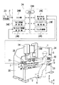
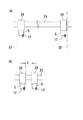
図1は本発明の実施の形態を示す図であり、図示する曲げ加工装置は、例えばプレスブレーキである。
Hereinafter, the present invention will be described with reference to the accompanying drawings by embodiments.
FIG. 1 is a diagram showing an embodiment of the present invention, and the illustrated bending apparatus is, for example, a press brake.
このプレスブレーキは、機械本体の両側に側板30を有し、該側板30の上部には、例えば油圧シリンダ34を介してラムである上部テーブル1が取り付けられ、該上部テーブル1には、中間板32を介してパンチPが装着されている。
This press brake has
また、側板30の下部には、下部テーブル2が配置され、該下部テーブル2には、保持板33を介してダイDが装着されている。
The lower table 2 is disposed below the
即ち、図1の曲げ加工装置は、下降式プレスブレーキであり、作業者Sが、下部テーブル2の後方に配置された後述するバックゲージ7の突き当て部5にワークWを突き当てて位置決めした後(図12のステップ111)、フットペダル6(図1)を踏み込んでONさせると、ラム制御部24Gを介して油圧シリンダ34が作動しラム1が下降することにより、前記パンチPとダイDの協働により該ワークWが曲げ加工される(図12のステップ112)。
That is, the bending apparatus of FIG. 1 is a descending press brake, and the operator S abuts and positions the workpiece W against an
前記下部テーブル2(図1)の後方には、前記当て部5を有するバックゲージ7が設けられ、該バックゲージ7は、例えばリンク機構(図示省略)を介して下部テーブル2に支持されている。
A
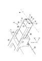
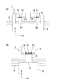
下部テーブル2の両側の前記リンク機構間には、ストレッチ25が(図1、図2)左右方向(X軸方向)に設けられ、該ストレッチ25には、前部に突き当て部5を有する突き当て部本体26がX軸モータMx(図示省略)で左右方向に移動自在に取り付けられ、更にリンク機構がY軸モータMy(図示省略)で前後方向(Y軸方向)に、またZ軸モータMz(図示省略)で上下方向(Z軸方向)にそれぞれ移動自在となっている。
A
この構成により、後述するバックゲージ制御部24F(図1)により、バックゲージ7が予め所定の位置に位置決めされる(図12のステップ108のYES)。
With this configuration, the
上記突き当て部5(図2)は、先端部5Aと中間部5Bと基端部5Cにより構成されている。
The abutting portion 5 (FIG. 2) includes a
上記先端部5Aは、その前面にワークWを突き当て、該先端部5Aは、中間部5Bに取り付けられていると共に、該中間部5Bの下方には、後述する動作状態表示手段10、11、12と、ワーク突き当て範囲表示手段13、14、15、16、17のコントローラ5Dが配置され、基端部5Cが前記本体26に直接取り付けられている。
The
上記先端部5Aの前面上部には、動作状態表示手段10、11、12 が、前面下部には、ワーク突き当て範囲表示手段13、14、15、16、17がそれぞれ設けられている。
On the front upper portion of the
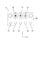
上記動作状態表示手段10、11、12は、突き当て部5の動作状態、例えば突き当て部5が移動時か位置決め完了時か等を表示し、複数個の(本実施形態では3つの)LED10、11、12により構成されている。
The operation state display means 10, 11, 12 display the operation state of the abutting
このうち、左端のLED10は(図3)作動時に黄色を呈し、突き当て部5が移動中であることを表示し、真ん中のLED11は作動時に青色を呈し、突き当て部5が位置決めを完了したことを表示し、右端のLED12は作動時に赤色を呈し、突き当て部5がアラームを発生したことを表示する。
Of these, the leftmost LED 10 (FIG. 3) is yellow when activated, indicating that the
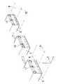
例えば、ワークW(図4)をバックゲージ突き当て部5に突き当てて位置決めする場合には、予め突き当て部5を所定位置に位置決めする必要があり、例えばX軸方向の最初の位置がX1、次の位置がX2とする。
For example, when positioning the workpiece W (FIG. 4) against the back
この場合、突き当て部5が最初の位置X1に位置決めされたときには真ん中のLED11が青色を呈するので、それを見た作業者は突き当て部5の位置決めが完了したことが分かり、該突き当て部5にワークWを突き当てて位置決めする。
In this case, when the abutting
そして、突き当て部5が次の位置X2まで移動する間は、左端のLED10が黄色を呈するので、それを見た作業者は突き当て部5が移動中であることが分かり、該突き当て部5にワークWを突き当てて位置決めするといった危険なことはやらない。
And while the
更に、突き当て部5(図5)を移動中に誤って左右方向(X軸方向)の限界値(図5(A)のオーバトラベルOT値)に到達させてしまった場合や、両突き当て部5を最小間隔値L(図5(B))以内に接近させてしまった場合には、前記右端のLED12が赤色を呈するので、作業者は突き当て部5がアラームを発生したことが分かり、直ちにそのアラーム発生の原因を除去する。
また、上記動作状態表示手段10、11、12は、複数個のLEDで構成したが、本発明はこれに限定されず、1個のLEDで構成することもでき、この場合には、1個のLEDが、同様に、突き当て部5の動作状態により黄色、青色、赤色を呈する。即ち、1個のLEDが、黄色の場合には、突き当て部5が移動中であることを表示し、青色の場合には、突き当て部5が位置決めを完了したことを表示し、赤色の場合には、突き当て部5がアラームを発生したことを表示する。
Furthermore, if the abutting portion 5 (FIG. 5) is accidentally made to reach the limit value in the left-right direction (X-axis direction) (the overtravel OT value in FIG. 5A) while moving, or both abutments When the
Moreover, although the said operation state display means 10, 11, 12 comprised with several LED, this invention is not limited to this, It can also comprise with one LED, In this case, one piece Similarly, the LEDs exhibit yellow, blue, and red depending on the operating state of the abutting
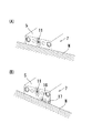
一方、ワーク突き当て範囲表示手段13、14、15、16、17は(図3)、突き当て部5の前面にワークWを(図6〜図7)突き当てる範囲を表示し、複数個の(本実施形態では5つの)LED13、14、15、16、17により構成されている。 On the other hand, the workpiece abutting range display means 13, 14, 15, 16, and 17 (FIG. 3) display a range in which the workpiece W is abutted on the front surface of the abutting portion 5 (FIGS. 6 to 7). It is comprised by LED13, 14, 15, 16, 17 (five in this embodiment).
例えば、図6に示すように、ワークW上の曲げ線mを曲げる場合であって、該ワークWの端面をバックゲージ7の左右2つの突き当て部5全体に平行に突き当てて位置決めしようとするときには、両突き当て部5のLED13、14、15、16、17を全て点灯することにより、ワークWを突き当てる範囲を表示する。
For example, as shown in FIG. 6, the bending line m on the workpiece W is bent, and the end surface of the workpiece W is to be positioned in parallel with the two left and
しかし、後述するように、左右2つの突き当て部5では、ワークWを突き当てる範囲が異なる場合もあり(図7(A))、1つの突き当て部5のLED13、14、15、16、17のいずれかを点灯するだけで、ワークWを突き当てる範囲を表示することもできる(図7(B))。
However, as will be described later, the two abutting
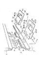
図8は、本発明による動作例を示す図であり、バックゲージ突き当て部5が所定位置に位置決めされた場合には、位置決め完了と判断され(図12のステップ108におけるYES)、位置決め完了を表示するLED(青色)を点灯すると共に、突き当て部5を停止させ(図12のステップ109)、更に、ワークWの突き当て範囲に属するLED13〜17を点灯させる(図12のステップ110)。
FIG. 8 is a diagram illustrating an operation example according to the present invention. When the back
そして、この点灯したLEDに誘導されて作業者はワークWを突き当て部5の前面に突き当てるが、ワークWを突き当て部5前面に平行に突き当てる正常な突き当てならば、図8(A)に示すように、光が漏れない。
Then, the operator is guided by the lit LED and abuts the workpiece W against the front surface of the abutting
しかし、ワークWを突き当て部5前面に斜めに突き当てる異常な突き当てならば、図8(B)に示すように、光が漏れる。
However, if it is an abnormal abutment that strikes the workpiece W diagonally against the front surface of the
従って、本発明によれば、突き当て部5前面下部に、ワーク突き当て範囲表示手段13〜17を設けたことにより、突き当ての正否を容易に判断でき、突き当てミスを無くすことができる。
Therefore, according to the present invention, by providing the workpiece abutting range display means 13 to 17 at the lower part of the front surface of the abutting
一方、上記下部テーブル2の(図1)近傍には、フットペダル6が配置され、作業者Sが前記したワーク突き当て範囲表示手段13(図2)、14、15、16、17に誘導されてワークWを突き当て部5に突き当てて位置決めした後(図12のステップ111)、このフットペダル6を踏み込んでONしたときに、それを検出したラム制御部24G(図1)が油圧シリンダ34を作動してラム1を下降させ、曲げ加工が行われる(図12のステップ112)。
On the other hand, a
このような構成を有するプレスブレーキのNC装置24は(図1)、CPU24Aと、入力部24Bと、加工情報決定部24Cと、突き当て情報決定部24Dと、表示手段制御部24Eと、バックゲージ制御部24Fと、ラム制御部24Gにより構成されている。
The press
CPU24Aは、本発明を実施するための動作手順(例えば図12に相当)に従って加工情報決定部24C、突き当て情報決定部24D、表示手段制御部24Eなど図1に示す装置全体を統括制御する。
The
入力部24Bは、例えば上部テーブル1に移動自在に取り付けられた操作盤により構成され、上位NC装置23から製品情報Jを入力し(図12のステップ101)、該入力された製品情報Jは、記憶部(図示省略)に記憶され、曲げ順、金型、金型レイアウトなどの決定に用いられる。
The
製品情報Jは、例えばCAD情報であって、ワークW(図9)の板厚、材質、曲げ線の長さ、製品の曲げ角度、フランジ寸法などの情報を含み、これらが立体姿図、展開図として構成されている。 The product information J is, for example, CAD information, and includes information such as the thickness, material, bending line length, bending angle of the product, and flange dimensions of the workpiece W (FIG. 9). It is configured as a diagram.
また、上位NC装置23は、例えば事務所に設置され、NC装置24は、この上位NC装置23に対する下位NC装置として、前記プレスブレーキが設けられている例えば工場に設置されている。
Further, the
そして、図1に示す例では、製品情報Jが前記上位NC装置23に内蔵されており、この製品情報Jを上位NC装置23から提供されたNC装置24が、本発明の動作を制御する(図12)。
In the example shown in FIG. 1, product information J is built in the
しかし、本発明は、これに限定されること無く、上位NC装置23も、NC装置24と同様に加工情報決定部24C、突き当て部情報決定部24Dなどを有しており、該上位NC装置23は、その内蔵する製品情報Jに基づいて所定のデータ処理を行うことにより、本発明の動作を直接に制御できる(図12)。
However, the present invention is not limited to this, and the
更に、前記NC装置24(図1)の入力部24Bには、上位NC装置23から製品情報Jを自動で入力するのでは無く、作業者S自身が製品情報Jを手動で入力することも可能である。
Further, the product information J can be manually input by the operator S instead of automatically inputting the product information J from the
加工情報決定部24Cは(図1)、前記製品情報Jに基づいて、ワークWの曲げ順、曲げ順(曲げ工程)ごとに使用される金型P、D、金型レイアウト、ワークWの位置、バックゲージ7の位置を決定する他、D値、L値をそれぞれ決定する(図12のステップ102)。
The machining information determination unit 24C (FIG. 1), based on the product information J, the molds P and D used for each bending order and bending order (bending process) of the workpiece W, the mold layout, and the position of the workpiece W. In addition to determining the position of the
例えば、図9に示すように、平坦なワークWの曲げ線m1〜m4部分を(1)〜(4)の順に曲げ加工し、最終的には、図示するように、フランジF1〜F4が立った製品を加工するものとすると、曲げ線の長さL1〜L4等を考慮して、曲げ順等を決定する。 For example, as shown in FIG. 9, the bending lines m1 to m4 of the flat work W are bent in the order of (1) to (4), and finally, the flanges F1 to F4 stand up as shown in the figure. If the product is to be processed, the bending order and the like are determined in consideration of the lengths L1 to L4 of the bending lines.
この場合、よく知られているように、バックゲージ7の位置は、製品情報Jに基づくワークWのフランジ寸法などにより決定される突き当て部5の左右方向(X軸方向)と前後方向(Y軸方向)と上下方向(Z軸方向)の位置である(図10)。
In this case, as is well known, the position of the
突き当て情報決定部24Dは(図1)、バックゲージ突き当て部5の動作状態、例えば移動中か(図12のステップ105)、アラームを発生しているか否か等(図12のステップ107)の動作状態を決定する。
The abutment
即ち、前記加工情報決定部24C(図1)により、曲げ順ごとのバックゲージ位置が決定されるが(図12のステップ102)、例えばX軸方向(図4)の最初の位置決め位置をX1、次の位置決め位置をX2とする。
That is, although the back gauge position for each bending order is determined by the processing information determination unit 24C (FIG. 1) (
この場合、既述したように、突き当て部5が位置X1とX2の間にあるときは、該突き当て部5の動作状態は、移動中であることから、前記突き当て情報決定部24Dは、その旨を決定し、例えば記憶部(図示省略)に、突き当て部5が位置X1とX2の間にあるときは、移動中であると記憶させる(図10のデータベース)。
In this case, as described above, when the abutting
また、既述したように、突き当て部5が位置X1又はX2に到達したときは、該突き当て部5の動作状態は、位置決め完了であることから、前記突き当て情報決定部24Dは、その旨を決定し、同様に、記憶部(図示省略)に、突き当て部5が位置X1又はX2に到達したときは、位置決め完了であると記憶させる。
Further, as described above, when the abutting
更に、既述したように、突き当て部5が左右方向(X軸方向)の限界値(図5(A))に到達したときや、両突き当て部5が最小間隔値L(図5(B))以内に接近したときは、該突き当て部5の動作状態は、アラーム状態にあることから、前記突き当て情報決定部24Dは、その旨を決定し、同様に、記憶部(図示省略)に、突き当て部5が左右方向(X軸方向)の限界値に到達したとき等は、アラーム状態であると記憶させる。
Furthermore, as described above, when the abutting
また、前記突き当て情報決定部24Dは(図1)、バックゲージ突き当て部5(図6〜図7)の前面にワークWを突き当てる場合に、そのワークWを突き当てる範囲に属するワーク突き当て範囲表示手段13〜17を決定する。
Further, the abutting
即ち、前記製品情報J(図1、図9)によれば、各曲げ工程ごとのワークWの突き当て部の形状を作成することができるので(工程図)、この工程図を用いて、ワーク突き当て部とバックゲージ突き当て部5との当接状態に基づき、ワーク突き当て範囲が分かる。
That is, according to the product information J (FIGS. 1 and 9), the shape of the abutting portion of the work W for each bending process can be created (process diagram). Based on the contact state between the abutting portion and the back
例えば、最も単純なワーク突き当て部の形状としては、既述した図6に示すように、左右方向全体にわたる平坦な端面形状があり、この場合には、曲げ線mの長さから判断して、端面が、バックゲージ7の2つの突き当て部5全体に突き当てられたときに、ワークWが傾斜せずに位置決めされる。
For example, as the shape of the simplest workpiece abutting portion, as shown in FIG. 6 described above, there is a flat end surface shape over the entire left and right direction. In this case, judging from the length of the bending line m When the end face is abutted against the entire two abutting
従って、この場合のワーク突き当て範囲は、バックゲージ突き当て部5の前面全体であることは明らかである。
Therefore, it is clear that the workpiece abutting range in this case is the entire front surface of the back
よって、突き当て情報決定部24Dによれば、そのワーク突き当て範囲に属するワーク突き当て範囲表示手段13〜17を、例えば図11の曲げ工程(曲げ順)1の○に示すように、決定する。
Therefore, according to the abutting
そして、この決定結果は、同様にデータベース化して記憶部(図示省略)に記憶しておく。 The determination result is similarly converted into a database and stored in a storage unit (not shown).
即ち、2つの突き当て部5に関しては、全てのLED13〜17
がワーク突き当て範囲に属し、作業者は、点灯した前記全てのLED13〜17に誘導されることにより、ワークWを容易に突き当てて位置決めすることができる。
That is, with respect to the two butting
Belongs to the workpiece abutting range, and the operator can easily abut and position the workpiece W by being guided by all the
また、例えばワーク突き当て部の形状としては、図7(A)に示すように、比較的幅(X軸方向)が狭いフランジF1 、F2 があり、この場合には、ワークWの位置、及び両フランジF1 、F2 のそれぞれの幅と、両者の間隔から判断して、バックゲージ7の2つの突き当て部5の一部に突き当てられたときに、ワークWが傾斜せずに位置決めされる。
Further, for example, as the shape of the workpiece abutting portion, there are flanges F 1 and F 2 having relatively narrow widths (X-axis direction) as shown in FIG. 7A. In this case, the position of the workpiece W , And the respective widths of both flanges F 1 and F 2 and the distance between them, the workpiece W does not tilt when it is abutted against part of the two abutting
従って、この場合のワーク突き当て範囲は、両バックゲージ突き当て部5の前面の一部であり、突き当て情報決定部24Dによれば、そのワーク突き当て範囲に属するワーク突き当て範囲表示手段13〜17を、例えば図11の曲げ順Xの○に示すように、決定し、この決定結果は、同様にデータベース化して記憶部(図示省略)に記憶しておく。
Accordingly, the workpiece abutting range in this case is a part of the front surface of both back
即ち、2つの突き当て部5のうちの左側の突き当て部5に関しては、LED14、15
が、右側の突き当て部5に関しては、LED16、17 がそれぞれワーク突き当て範囲に属し、作業者は、点灯した前記LED14、15とLED16、17に誘導されることにより、ワークWを容易に突き当てて位置決めすることができる。
That is, regarding the
However, regarding the
更には、ワーク突き当て部の形状としては、例えば図7(B)に示すように、極めて幅が狭いフランジFがあり、この場合には、バックゲージ7の一方の突き当て部5の一部に突き当てられたときに、ワークWが傾斜せずに位置決めされる。
Furthermore, as a shape of the workpiece abutting portion, for example, as shown in FIG. 7B, there is a flange F having a very narrow width. In this case, a part of one abutting
従って、この場合のワーク突き当て範囲は、1つのバックゲージ突き当て部5の前面の一部であり、突き当て情報決定部24Dによれば、そのワーク突き当て範囲に属するワーク突き当て範囲表示手段14〜16を、例えば図11の曲げ順Yの○に示すように、決定し、この決定結果は、同様にデータベース化して記憶部(図示省略)に記憶しておく。
Therefore, the workpiece abutting range in this case is a part of the front surface of one back
即ち、1つの左側の突き当て部5に関して、LED14〜16
がワーク突き当て範囲に属し、作業者は、点灯した前記LED14〜16に誘導されることにより、ワークWを容易に突き当てて位置決めすることができる。
That is, the
Belongs to the workpiece abutting range, and the operator can easily abut and position the workpiece W by being guided by the lit
一方、表示手段制御部24Eは(図1)、前記突き当て情報決定部24Dの決定に基づいて、既述した動作状態表示手段10、11、12を駆動制御する。
On the other hand, the display means
即ち、前記突き当て情報決定部24Dによれば、バックゲージの突き当て部5が移動中か否か等の動作状態が決定されるが(図10)、この決定に基づいて、表示手段制御部24Eは、3つのLEDから成る動作状態表示手段10、11、1を駆動制御する。
That is, according to the abutment
例えば、表示手段制御部24Eは(図1)、バックゲージ7の突き当て部5を駆動するX軸モータMx(図示省略)、X軸モータMx(図示省略)、Z軸モータMz(図示省略)のエンコーダからのフィードバック信号を入力することにより、該突き当て部5の位置(X軸方向、Y軸方向、Z軸方向)を検出することができる。
For example, the display means
これにより、表示手段制御部24Eが突き当て部5の位置を検出すると共に、前記図10のデータベースを参照し、例えば突き当て部5が位置X1、X2の間にあれば、該突き当て部5は移動中であると判断し、既述したコントローラ5D(図2)を制御することにより、LED10(黄色)を電源に接続し、該LED10(黄色)を点灯する(図10のステップ105⇒ステップ106)。
Thereby, the display means
また、表示手段制御部24Eは(図1)、前記突き当て情報決定部24Dの決
定に基づいて、既述したワーク突き当て範囲表示手段13〜17(図2、図3)も駆動制御する。
Further, the display means
即ち、前記突き当て情報決定部24Dによれば、バックゲージの突き当て部5にワークWを突き当てる場合の該ワーク突き当て範囲に属するワーク突き当て範囲表示手段13〜17が決定されるが(図11)、この決定に基づいて、表示手段制御部24Eは、所定のワーク突き当て範囲表示手段13〜17を駆動制御する。
That is, according to the abutting
例えば、表示手段制御部24Eは(図1)、所定の製品(図9)を加工する場合に、前記図11のデータベースを参照し、曲げ順1のときは(図11)、左右の2つの突き当て部5に関して、全てのLED13〜17
がワーク突き当て範囲に属するので、曲げ順1の加工時には、突き当て部5を所定位置に位置決めした後(図12のステップ108⇒ステップ109)、既述したコントローラ5D(図2)を制御することにより、全てのLED13〜17を電源に接続し、各LEDを点灯する(図12のステップ110)。
For example, the display means
Belongs to the workpiece abutting range, and at the time of processing in the
バックゲージ制御部24Fは(図1)、X軸モータMx(図示省略)、Y軸モータMy(図示省略)、Z軸モータMz(図示省略)を制御することにより、前記バックゲージ7を所定位置に位置決めし(図4)、ラム制御部24Gは(図1)、ラム駆動源である油圧シリンダ34を制御することより、ラム1を駆動制御する。
The back gauge control unit 24F (FIG. 1) controls the X-axis motor Mx (not shown), the Y-axis motor My (not shown), and the Z-axis motor Mz (not shown) to place the
以下、上記構成を有する本発明の動作を、図12に基づいて、説明する。 The operation of the present invention having the above configuration will be described below with reference to FIG.
(1)
ワーク突き当て範囲表示手段13〜17を決定するまでの動作。
図11のステップ101において、上位NC装置23から製品情報Jを入力し、ス
テップ102において、曲げ順、金型、金型レイアウト、D値、L値、ワーク位置、バックゲージ位置を決定し、ステップ103において、バックゲージ突き当て部5の動作状態、ワーク突き当て範囲表示手段13〜17を決定する。
(1)
Operations until the workpiece contact range display means 13 to 17 are determined.
In
即ち、CPU24Aは(図1)、上位NC装置23から製品情報Jが入力したことを検知すると、加工情報決定部24Cを介して、既述した曲げ順、金型、金型レイアウトなどを、突き当て情報決定部24Dを介して、バックゲージ突き当て部5の動作状態、ワーク突き当て範囲表示手段13〜17をそれぞれ決定し、決定した動作状態等は(図10、図11)は、データベース化して記憶部(図示省略)に記憶させておく。
That is, when the
(2)
バックゲージ突き当て部5の位置決め動作。
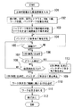
図12のステップ104において、バックゲージ突き当て部5を作動し、ステップ105において、突き当て部5が移動中か否かを判断し、移動中の場合には(YES)、ステップ106において、LED10(黄色)を点灯し、移動中でない場合には( NO)、ステップ104に戻って同じ動作を繰り返す。
(2)
Positioning operation of the back
In
即ち、CPU24Aは(図1)、加工情報決定部24Cと突き当て情報決定部24Dによる動作が終了すると、バックゲージ制御部24Fを介して、X軸モータMx(図示省略)等を駆動制御し、バックゲージ7の突き当て部5を作動させる。
That is, when the operation by the machining information determination unit 24C and the abutment
この間、CPU24Aは、既述したように、表示手段制御部24Eに前記X軸モータMx等のエンコーダからのフィードバック信号を入力させて、該突き当て部5の位置(X軸方向、Y軸方向、Z軸方向)を検出すると共に、前記図10のデータベースを参照し、該突き当て部5は移動中であると判断した場合には、コントローラ5D(図2)を制御することにより、移動中であることを表示するLED10(黄色)を点灯する。
During this time, as described above, the
また、図12のステップ107において、アラームが発生したか否かを判断し、発生した場合には(YES)、ステップ113において、LED12(赤色)を点灯すると共に、バックゲージ突き当て部5を停止させ、アラームが発生しない場合には(ステップ107のNO)、ステップ108において、位置決め完了か否かを判断し、位置決め完了の場合には(YES)、ステップ109において、LED11(青色)を点灯すると共に、バックゲージ突き当て部5を停止させ、位置決めが完了しない場合には(ステップ108のNO)、ステップ105に戻って同じ動作を繰り返する。
Further, in
CPU24Aは、同様に表示手段制御部24Eを介して突き当て部5の位置を検出すると共に、前記図10のデータベースを参照し、該突き当て部5はアラームを発生した、又は位置決めを完了した(図5)と判断した場合には、コントローラ5D(図2)を制御することにより、アラームを表示するLED12(赤色)、又は位置決め完了を表示するLED11(青色)を点灯し、その後、バックゲージ突き当て部5を停止させる。
Similarly, the
そして、突き当て部5がアラームを発生した場合には、突き当て部5は停止したままであり、作業者はその原因を除去する。
When the abutting
例えば突き当て部5が誤って左右方向の限界値に到達した場合には(図5(A))、作業者は、突き当て部5を手動で元の位置に戻し、次の動作に備える。
For example, when the abutting
(3)ワークWの位置決め動作と曲げ加工動作。
しかし、突き当て部5が位置決め完了の場合には(図12のステップ108のYES)、既述したように、LED11(青色)を点灯すると共に、バックゲージ突き当て部5を停止させた後(ステップ109)、更に、ワーク突き当て範囲に属するLEDを点灯する(ステップ110)。
(3) Positioning operation and bending operation of the workpiece W.
However, when the abutting
即ち、CPU24Aは(図1)、バックゲージ制御部24Fを介して突き当て部5を所定位置に位置決めした後、前記図11のデータベースを参照し、これから行われる曲げ工程(曲げ順)に対応して点灯すべきLEDはどれかを判断し、表示手段制御部24Eを介して、所定のワーク突き当て範囲に属するLEDを点灯する。
That is, the
従って、作業者Sは(図1)、この点灯したLED13〜17(図6〜図7)に誘導されることにより、ワークWを突き当て部5前面の所定の位置に極めて容易に位置決めすることができ、その後、フットペダル6(図1)を踏み込めば、ラム1が下降し、該ワークWに所定の曲げ加工が行われる(図12のステップ112)。
Accordingly, the worker S (FIG. 1) is very easily positioned at a predetermined position on the front surface of the abutting
本発明は、バックゲージの突き当て部が、動作状態を表示するようにして作業者の安全を図り、ワークを突き当てる範囲を明確にして作業者を誘導し、更に、周囲が暗くても作業者に対して突き当て部の存在を明示する曲げ加工装置に利用され、具体的には、下降式プレスブレーキのみならず、上昇式プレスブレーキにも適用され、いずれの場合にも、極めて有用である。 In the present invention, the abutting part of the back gauge displays the operation state to ensure the safety of the operator, guides the operator by clarifying the range where the workpiece is abutted, and works even when the surroundings are dark. It is used in a bending machine that clearly indicates the presence of the abutting part to the user. Specifically, it is applied not only to the descending press brake but also to the ascending press brake. is there.
1 上部テーブル
2 下部テーブル
5 突き当て部
6 フットペダル
7 バックゲージ
10、11、12
動作状態表示手段
13、14、15、16、17 ワーク突き当て範囲表示手段
23 上位NC装置
24 NC装置
24A CPU
24B 入力部
24C 加工情報決定部
24D 突き当て情報決定部
24E 表示手段制御部
24F バックゲージ制御部
24G ラム制御部
25 ストレッチ
26 突き当て部本体
30 側板
32 中間板
33 保持板
34 油圧シリンダ
D ダイ
P パンチ
W ワーク
DESCRIPTION OF
Operating state display means 13, 14, 15, 16, 17 Work abutting range display means 23
24B Input unit 24C Processing
Claims (7)
製品情報に基づいて、曲げ工程ごとに、金型、金型レイアウト、ワークの位置、バックゲージの位置を決定する加工情報決定部と、
バックゲージの突き当て部が移動中か否か等の動作状態を決定する突き当て情報決定部と、
該突き当て部情報決定部の決定に基づいて、バックゲージ突き当て部に設けられた前記動作状態表示手段を駆動制御する表示手段制御部を有することを特徴とする曲げ加工装置。 An operation state display means provided in the back gauge abutting portion;
Based on product information, for each bending process, a processing information determination unit that determines the mold, mold layout, workpiece position, back gauge position,
An abutment information determination unit for determining an operation state such as whether or not the abutment unit of the back gauge is moving;
A bending apparatus, comprising: a display control unit that drives and controls the operation state display unit provided in the back gauge butting unit based on the determination of the butting unit information determining unit.
Priority Applications (1)
| Application Number | Priority Date | Filing Date | Title |
|---|---|---|---|
| JP2007281609A JP5187728B2 (en) | 2007-10-30 | 2007-10-30 | Bending machine |
Applications Claiming Priority (1)
| Application Number | Priority Date | Filing Date | Title |
|---|---|---|---|
| JP2007281609A JP5187728B2 (en) | 2007-10-30 | 2007-10-30 | Bending machine |
Publications (2)
| Publication Number | Publication Date |
|---|---|
| JP2009106972A true JP2009106972A (en) | 2009-05-21 |
| JP5187728B2 JP5187728B2 (en) | 2013-04-24 |
Family
ID=40776076
Family Applications (1)
| Application Number | Title | Priority Date | Filing Date |
|---|---|---|---|
| JP2007281609A Expired - Fee Related JP5187728B2 (en) | 2007-10-30 | 2007-10-30 | Bending machine |
Country Status (1)
| Country | Link |
|---|---|
| JP (1) | JP5187728B2 (en) |
Cited By (5)
| Publication number | Priority date | Publication date | Assignee | Title |
|---|---|---|---|---|
| JP2013188773A (en) * | 2012-03-13 | 2013-09-26 | Shinko Engineering & Maintenance Co Ltd | Device and method for detecting positional deviation of workpiece and computer program |
| AT514292A1 (en) * | 2013-06-20 | 2014-11-15 | Trumpf Maschinen Austria Gmbh | Stop device for a bending machine |
| JP2019534790A (en) * | 2016-10-14 | 2019-12-05 | トルンプ マシーネン オーストリア ゲゼルシャフト ミット ベシュレンクテル ハフツング ウント コンパニー コマンディトゲゼルシャフト | Back gauge for bending machine and method for positioning back gauge |
| JP2021020239A (en) * | 2019-07-29 | 2021-02-18 | 株式会社アマダ | Back gauge device of press brake and press brake |
| WO2021161422A1 (en) * | 2020-02-12 | 2021-08-19 | 株式会社ニコン | Machining system and placement device |
Citations (3)
| Publication number | Priority date | Publication date | Assignee | Title |
|---|---|---|---|---|
| JPH0447818U (en) * | 1990-08-31 | 1992-04-23 | ||
| JP2005000980A (en) * | 2003-06-16 | 2005-01-06 | Amada Co Ltd | Striking/moving/positioning device |
| JP2006205172A (en) * | 2005-01-25 | 2006-08-10 | Amada Co Ltd | Bending apparatus |
-
2007
- 2007-10-30 JP JP2007281609A patent/JP5187728B2/en not_active Expired - Fee Related
Patent Citations (3)
| Publication number | Priority date | Publication date | Assignee | Title |
|---|---|---|---|---|
| JPH0447818U (en) * | 1990-08-31 | 1992-04-23 | ||
| JP2005000980A (en) * | 2003-06-16 | 2005-01-06 | Amada Co Ltd | Striking/moving/positioning device |
| JP2006205172A (en) * | 2005-01-25 | 2006-08-10 | Amada Co Ltd | Bending apparatus |
Cited By (8)
| Publication number | Priority date | Publication date | Assignee | Title |
|---|---|---|---|---|
| JP2013188773A (en) * | 2012-03-13 | 2013-09-26 | Shinko Engineering & Maintenance Co Ltd | Device and method for detecting positional deviation of workpiece and computer program |
| AT514292A1 (en) * | 2013-06-20 | 2014-11-15 | Trumpf Maschinen Austria Gmbh | Stop device for a bending machine |
| JP2019534790A (en) * | 2016-10-14 | 2019-12-05 | トルンプ マシーネン オーストリア ゲゼルシャフト ミット ベシュレンクテル ハフツング ウント コンパニー コマンディトゲゼルシャフト | Back gauge for bending machine and method for positioning back gauge |
| US11267030B2 (en) | 2016-10-14 | 2022-03-08 | Trumpf Maschinen Austria Gmbh & Co. Kg | Backgauge for a bending machine and method for positioning a backgauge of this kind |
| JP7032393B2 (en) | 2016-10-14 | 2022-03-08 | トルンプ マシーネン オーストリア ゲゼルシャフト ミット ベシュレンクテル ハフツング ウント コンパニー コマンディトゲゼルシャフト | How to position back gauges and back gauges for bending machines |
| JP2021020239A (en) * | 2019-07-29 | 2021-02-18 | 株式会社アマダ | Back gauge device of press brake and press brake |
| JP7324642B2 (en) | 2019-07-29 | 2023-08-10 | 株式会社アマダ | Back gauge device for press brake and press brake |
| WO2021161422A1 (en) * | 2020-02-12 | 2021-08-19 | 株式会社ニコン | Machining system and placement device |
Also Published As
| Publication number | Publication date |
|---|---|
| JP5187728B2 (en) | 2013-04-24 |
Similar Documents
| Publication | Publication Date | Title |
|---|---|---|
| JP5187728B2 (en) | Bending machine | |
| JP4969049B2 (en) | Bending machine | |
| JP2004160547A (en) | Bending machine | |
| JP4565633B2 (en) | Bending machine | |
| JP4404407B2 (en) | Press brake | |
| JP4743688B2 (en) | Bending machine | |
| US8931317B2 (en) | Bending method and machine thereof | |
| CN111867746A (en) | Optical safety device for plate bending machine, plate bending machine and optical monitoring method | |
| JP5500714B2 (en) | Movable axis position management device | |
| CN113939731A (en) | On-line laser contour measurement inspection system | |
| JP3668895B1 (en) | Bending method and apparatus | |
| CN111164525B (en) | Program generation device, welding system, and program generation method | |
| JP2005296966A (en) | Bending method and bending device | |
| CN100548522C (en) | Bending device | |
| JP5041572B2 (en) | Bending machine | |
| JP4836165B2 (en) | Bending method and apparatus | |
| JP2006305609A (en) | Bending apparatus | |
| JP2000015340A (en) | Bending method and apparatus thereof | |
| JP2006297424A (en) | Method and device for positioning workpiece in bending | |
| JP2006122956A (en) | Bending apparatus | |
| JP2004042096A (en) | Bending device | |
| JP2003326317A (en) | Device for positioning workpiece | |
| JP2003181542A (en) | Bending device | |
| JP6453544B2 (en) | Electric press and control method of electric press | |
| JP2003094116A (en) | Bending machine |
Legal Events
| Date | Code | Title | Description |
|---|---|---|---|
| A621 | Written request for application examination |
Free format text: JAPANESE INTERMEDIATE CODE: A621 Effective date: 20100724 |
|
| A977 | Report on retrieval |
Free format text: JAPANESE INTERMEDIATE CODE: A971007 Effective date: 20120516 |
|
| A131 | Notification of reasons for refusal |
Free format text: JAPANESE INTERMEDIATE CODE: A131 Effective date: 20120518 |
|
| A521 | Request for written amendment filed |
Free format text: JAPANESE INTERMEDIATE CODE: A523 Effective date: 20120714 |
|
| TRDD | Decision of grant or rejection written | ||
| A01 | Written decision to grant a patent or to grant a registration (utility model) |
Free format text: JAPANESE INTERMEDIATE CODE: A01 Effective date: 20130116 |
|
| A61 | First payment of annual fees (during grant procedure) |
Free format text: JAPANESE INTERMEDIATE CODE: A61 Effective date: 20130116 |
|
| FPAY | Renewal fee payment (event date is renewal date of database) |
Free format text: PAYMENT UNTIL: 20160201 Year of fee payment: 3 |
|
| R150 | Certificate of patent or registration of utility model |
Ref document number: 5187728 Country of ref document: JP Free format text: JAPANESE INTERMEDIATE CODE: R150 Free format text: JAPANESE INTERMEDIATE CODE: R150 |
|
| S533 | Written request for registration of change of name |
Free format text: JAPANESE INTERMEDIATE CODE: R313533 |
|
| R350 | Written notification of registration of transfer |
Free format text: JAPANESE INTERMEDIATE CODE: R350 |
|
| S533 | Written request for registration of change of name |
Free format text: JAPANESE INTERMEDIATE CODE: R313533 |
|
| R350 | Written notification of registration of transfer |
Free format text: JAPANESE INTERMEDIATE CODE: R350 |
|
| LAPS | Cancellation because of no payment of annual fees |