JP2005296966A - Bending method and bending device - Google Patents
Bending method and bending device Download PDFInfo
- Publication number
- JP2005296966A JP2005296966A JP2004112929A JP2004112929A JP2005296966A JP 2005296966 A JP2005296966 A JP 2005296966A JP 2004112929 A JP2004112929 A JP 2004112929A JP 2004112929 A JP2004112929 A JP 2004112929A JP 2005296966 A JP2005296966 A JP 2005296966A
- Authority
- JP
- Japan
- Prior art keywords
- bending
- workpiece
- light
- positioning
- light beam
- Prior art date
- Legal status (The legal status is an assumption and is not a legal conclusion. Google has not performed a legal analysis and makes no representation as to the accuracy of the status listed.)
- Pending
Links
- 238000005452 bending Methods 0.000 title claims abstract description 97
- 238000000034 method Methods 0.000 title claims description 31
- 230000003287 optical effect Effects 0.000 claims abstract description 39
- 238000010586 diagram Methods 0.000 claims description 28
- 230000004075 alteration Effects 0.000 abstract 1
- 239000002184 metal Substances 0.000 abstract 1
- 101100328887 Caenorhabditis elegans col-34 gene Proteins 0.000 description 12
- 238000003860 storage Methods 0.000 description 10
- 238000004088 simulation Methods 0.000 description 5
- 238000003754 machining Methods 0.000 description 4
- 230000002452 interceptive effect Effects 0.000 description 2
- 230000002411 adverse Effects 0.000 description 1
- FFBHFFJDDLITSX-UHFFFAOYSA-N benzyl N-[2-hydroxy-4-(3-oxomorpholin-4-yl)phenyl]carbamate Chemical compound OC1=C(NC(=O)OCC2=CC=CC=C2)C=CC(=C1)N1CCOCC1=O FFBHFFJDDLITSX-UHFFFAOYSA-N 0.000 description 1
- 230000000903 blocking effect Effects 0.000 description 1
- 230000007423 decrease Effects 0.000 description 1
- 230000000994 depressogenic effect Effects 0.000 description 1
- 238000004519 manufacturing process Methods 0.000 description 1
- 238000003892 spreading Methods 0.000 description 1
Images
Landscapes
- Bending Of Plates, Rods, And Pipes (AREA)
Abstract
Description
本発明は、光学式安全装置を有する曲げ加工装置における曲げ加工方法、及びその装置に関する。 The present invention relates to a bending method in a bending apparatus having an optical safety device, and the apparatus.
従来より、曲げ加工装置、例えばプレスブレーキにおいては、労働災害を防止すべく、機械本体前方の作業者側に、異物検出用の光学式安全装置を設置し、作業者の手足などの異物が光線を遮った場合には、上記光学式安全装置が作動して加工中のラムを停止させるようになっている。 Conventionally, in order to prevent occupational accidents in bending machines, such as press brakes, an optical safety device for detecting foreign objects has been installed on the worker side in front of the machine body, and foreign objects such as workers' limbs are exposed to light rays. In the case of blocking, the optical safety device operates to stop the ram being processed.
しかし、曲げ加工の進行に伴って、ワークが跳ね上がると、この跳ね上がったワークが遮光するので、上記光学式安全装置は、ワークを異物と見做して加工中のラムを停止させてしまい、そのため、加工効率が低下する。 However, if the workpiece springs up as the bending process progresses, the jumped workpiece shields the light, so the optical safety device considers the workpiece as a foreign object and stops the ram being processed. , Processing efficiency decreases.
そこで、このような事態を回避するために、種々の手段が講じられている(例えば特公昭62−34446号、又は特開平10−328741号公報若しくは特開平5−277564号公報に開示)。 In order to avoid such a situation, various means have been taken (for example, disclosed in Japanese Patent Publication No. 62-34446, Japanese Patent Laid-Open No. 10-328741, or Japanese Patent Laid-Open No. 5-277564).
上記特公昭62−34446号公報に開示されている手段は、パンチがワークに接触後に光線を無効とすることにより、その後は、ワークが遮光しても、ラムを停止させることなく加工を続行させている。 The means disclosed in the above Japanese Patent Publication No. 62-34446 invalidates the light beam after the punch has contacted the workpiece, and then continues the machining without stopping the ram even if the workpiece is shielded from light. ing.
しかし、この手段によれば、既にフランジがあるワークを加工する場合には、加工前のワーク位置決め時に、該フランジが遮光してしまい、その時点から光学式安全装置が使用できなくなる。 However, according to this means, when machining a workpiece that already has a flange, the flange shields light when positioning the workpiece before machining, and the optical safety device cannot be used from that point.
その結果、作業者にとっては、極めて危険な状態での加工を強いられることになる。 As a result, the operator is forced to perform processing in an extremely dangerous state.
また、上記特開平10−328741号公報(又は特開平5−277564号公報)に開示されている手段は、光学式安全装置の複数の光軸のうちの所定の光軸を、製品形状に応じて、非遮光位置に位置決め可能とすることにより、フランジ形状や寸法に影響されることなく、常時光学式安全装置を使用できるようにしている。 Further, the means disclosed in the above-mentioned Japanese Patent Laid-Open No. 10-328741 (or Japanese Patent Laid-Open No. 5-277564) uses a predetermined optical axis among a plurality of optical axes of the optical safety device according to the product shape. Thus, by enabling positioning at the non-light-shielding position, the optical safety device can always be used without being affected by the flange shape and dimensions.
しかし、近年のように、多種少量生産が盛んになり、且つ複雑な形状の加工が増えている場合には、工程ごとに、前記所定の光軸を移動位置決めするので光線の配置をその都度変更しなければならない(光軸合わせの調整を含む)。 However, as in recent years, when a large number of small-scale production is prosperous and the processing of complicated shapes is increasing, the predetermined optical axis is moved and positioned for each process, so the arrangement of light rays is changed each time. (Including adjustment of optical axis alignment).
その結果、作業効率が極めて低く、生産性に悪影響を及ぼす。 As a result, work efficiency is extremely low, which adversely affects productivity.
本発明の目的は、光学式安全装置を有する曲げ加工装置において、各工程ごとに、複数光線のうちのワーク位置決め時に該ワークが遮光する光線を、予め無効とし、その他の光線を有効とすることにより、光学式安全装置を使用できるようにして作業者の安全を確保すると共に、工程ごとのワーク位置決め時における光線配置変更を不要にして作業効率の向上を図ることにある。 It is an object of the present invention to preliminarily invalidate light beams that are blocked by a workpiece when positioning a workpiece among a plurality of light beams and enable other light beams for each process in a bending apparatus having an optical safety device. Thus, the safety of the operator can be ensured by using the optical safety device, and the work efficiency can be improved by eliminating the need for changing the arrangement of the light beams at the time of positioning the work for each process.
上記課題を解決するために、本発明は、
機械本体前方に複数の光線L1 〜L7 を張り巡らす投光器2と受光器3から成る光学式安全装置1を有し、パンチPとダイDによりワークWを曲げ加工する曲げ加工装置において、
製品情報により決定される曲げ順、金型に基づいて、各曲げ工程ごとのワーク位置決め時におけるワークWの姿勢状態を示す図αを作成した後、該ワーク位置決め姿勢状態図αに基づいて、ワーク位置決め時におけるワークWと複数の各光線L1 〜L7 との干渉度合いを、各曲げ工程1、2・・・ごとに判断し、該判断結果δに基づいて、各曲げ工程1、2・・・ごとに、ワークWと干渉する光線を無効と判定することを特徴とする曲げ加工方法、及び
機械本体前方に複数の光線L1 〜L7 を張り巡らす投光器2と受光器3から成る光学式安全装置1を有、パンチPとダイDによりワークWを曲げ加工する曲げ加工装置において、
製品情報に基づいて、曲げ順、金型を決定する曲げ順等決定手段20Dと、
各曲げ工程ごとのワーク位置決め時におけるワークWの姿勢状態を示す図αを作成するワーク位置決め姿勢状態図作成手段20Eと、
該ワーク位置決め姿勢状態図αに基づいて、ワーク位置決め時におけるワークWと複数の各光線L1 〜L7 との干渉度合いを、各曲げ工程1、2・・・ごとに判断する干渉度合い判断手段20Gと、
該判断結果δに基づいて、各曲げ工程1、2・・・ごとに、ワークWと干渉する光線を無効と判定し、ワークWと干渉しない光線を有効と判定する光線有効・無効判定手段20Hを有することを特徴とする曲げ加工装置という技術的手段を講じている。
In order to solve the above problems, the present invention provides:
In a bending apparatus that has an
Based on the bending order determined by the product information and the mold, after creating a figure α showing the posture state of the workpiece W at the time of workpiece positioning for each bending process, The degree of interference between the workpiece W and the plurality of light beams L 1 to L 7 at the time of positioning is determined for each
A bending order determining means 20D for determining a bending order and a mold based on product information;
Workpiece positioning posture state diagram creating means 20E for creating a figure α showing the posture state of the workpiece W at the time of workpiece positioning for each bending process;
Interference degree determination means for determining the degree of interference between the workpiece W and the plurality of light beams L 1 to L 7 for each
Based on the determination result δ, for each
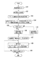
上記本発明の構成によれば、例えば図4に示すようなワーク位置決め姿勢状態図αを作成し(図6のステップ103)、このワーク位置決め姿勢状態図α(図3)を用いて、ワーク位置決め時におけるワークWと複数の光線L1 〜L7 との干渉の度合いを判断し(図6のステップ104)、ワークWと干渉する光線を無効と判定し(図6のステップ105のYES→ステップ106)、ワークWと干渉しない光線を有効と判定することにより(図6ステップ105のNO→ステップ110)、例えば各曲げ工程ごとに複数の光線のうちのどの光線が有効か無効かを明らかにした光線有効・無効判定テーブルβ(図5)を作成しておき(図6のステップ107)、曲げ加工時には(図6のステップ108)、この判定テーブルβを参照する。
According to the above configuration of the present invention, for example, a workpiece positioning posture state diagram α as shown in FIG. 4 is created (
これにより、有効とされた(図5の○印)光線が、曲げ加工時に遮光されると、従来どおりラム4が(図1)停止するので、光学式安全装置1は使用可能となり、従って、作業者の安全は確保され、また、前記したように、ワーク位置決め時におけるワークWと光線との干渉度合いが判断され、光線の有効・無効の判定が自動的に行われるので、従来のような工程ごとのワーク位置決め時における光線配置変更が不要となり、従って、作業効率が向上する。
As a result, when the effective light beam (marked with a circle in FIG. 5) is shielded during bending, the
上記のとおり、本発明によれば、光学式安全装置を有する曲げ加工装置において、各工程ごとに、複数光線のうちのワーク位置決め時に該ワークが遮光する光線を、予め無効とし、その他の光線を有効とすることにより、光学式安全装置を使用できるようにして作業者の安全を確保すると共に、工程ごとのワーク位置決め時における光線配置変更を不要にして作業効率の向上を図るという効果を奏する。 As described above, according to the present invention, in the bending apparatus having the optical safety device, for each step, the light beam shielded by the workpiece during positioning of the workpiece is invalidated in advance, and other light beams are By making it effective, it is possible to use the optical safety device to ensure the safety of the worker, and it is possible to improve the work efficiency by eliminating the need to change the arrangement of light beams at the time of workpiece positioning for each process.
以下、本発明を、実施の形態により添付図面を参照して、説明する。
図1は本発明の実施の形態を示す図である。
Hereinafter, the present invention will be described with reference to the accompanying drawings by embodiments.
FIG. 1 is a diagram showing an embodiment of the present invention.
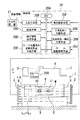
図1に示す曲げ加工装置は、例えばプレスブレーキである。 The bending apparatus shown in FIG. 1 is a press brake, for example.
このプレスブレーキは、機械本体の両側に側板8、9を有し、該側板8、9の上部には、ラム駆動源である例えば油圧シリンダ6、7が設けられ、該油圧シリンダ6、7により、上部テーブル4が上下動し、該上部テーブル4には、パンチPが装着されている。
This press brake has
また、側板8、9の下方には、下部テーブル5が配置され、該下部テーブル5には、ダイDが装着されている。
A lower table 5 is disposed below the
即ち、図1の曲げ加工装置は、下降式プレスブレーキであり、下部テーブル5の後方に配置された後述するバックゲージの突当10、11にワークWを突き当てて位置決めした後、油圧シリンダ6、7を作動し下部テーブル5を下降させれば、前記パンチPとダイDの協働により該ワークWが折り曲げられる。
That is, the bending apparatus shown in FIG. 1 is a descending press brake, and after positioning the work W against the
この下部テーブル5の前方には、図示するように、投光器2と受光器3により構成された光学式安全装置1が設置され、加工前に予め投光器2から複数の光線L1 〜L7 (例えばレーザ光)が投光され、その光線を受光器3で受光するようになっている。
As shown in the figure, an
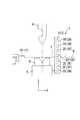
上記投光器2は(図2)、複数の発光素子2A〜2Gにより、受光器3は、各発光素子2A〜2Gに対応した複数の受光素子3A〜3Gによりそれぞれ構成されている。
The light projector 2 (FIG. 2) includes a plurality of
これにより、光学式安全装置1は(図1)、プレスブレーキ機械本体前方に、複数の光線L1 〜L7 を張り巡らすことができ、曲げ加工中に、該機械前方で作業者の手足、その他異物がこれら光線のうちのいずれかを遮光すると、下降中のラム4が停止することにより、作業者の危険は回避され、安全が確保される。
Accordingly, the optical safety device 1 (FIG. 1) can stretch a plurality of light beams L 1 to L 7 in front of the press brake machine main body, and the operator's limbs in front of the machine during bending, If any other foreign object blocks any of these light beams, the descending
このような光学式安全装置1において、本発明によれば、上記複数の光線L1 〜L7 は、曲げ工程別に、個別に有効・無効とすることができる。
In such an
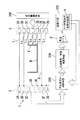
例えば、ワーク位置決め時のワークWの姿勢状態が、図3のようであるとすれば、複数の光線L1 〜L7 のうちの光線L1 、L2 とL6 、L7 は、受光器3側に受光されるが、光線L3 、L4 、L5 は、ワークWのフランジFと干渉して遮光される。 For example, posture state of the workpiece W during the work positioning, if it is as in Figure 3, light ray L 1, L 2 and L 6, L 7 of the plurality of light beams L 1 ~L 7 is photoreceiver Although the light is received on the third side, the light beams L 3 , L 4 , and L 5 are blocked by interference with the flange F of the workpiece W.
従って、上記フランジFと干渉する光線L3 、L4 、L5 を無効とし(ワークWが遮光してもラム4が起動可能)、その他のフランジFと干渉しない光線L1 、L2 とL6 、L7 を有効とする(ワークWが遮光するとラム4は停止する)
。
Accordingly, the light beams L 3 , L 4 , and L 5 that interfere with the flange F are invalidated (the
.
このような動作を、後述するように(図6のステップ101〜107)曲げ加工前に予めシミュレーションすることにより、曲げ加工時には、前記有効とした光線(例えば光線L1 、L2 とL6 、L7 (図3))が働くので、既述したように、本発明によれば、光学式安全装置1が使用可能となり、作業者の安全を確保し、また、各工程ごとのワーク位置決め時の光線配置変更が不要となり、作業効率が向上する。
As will be described later (
上記上部テーブル4には(図1)、例えば操作ボックスから成る入出力手段20Bが移動可能に取り付けられ、該入出力手段20Bは、各種のキーなどの入力手段や、画面などの出力手段が設けられ、前記したシミュレーションは(図5のステップ101〜ステップ107)、例えば画面上で行うことができる。
In the upper table 4 (FIG. 1), for example, an input / output means 20B composed of an operation box is movably attached. The input / output means 20B is provided with input means such as various keys and output means such as a screen. The above-described simulation (
このような構成を有するプレスブレーキのNC装置20は(図1)、CPU20Aと、入出力手段20Bと、記憶手段20Cと、曲げ順等決定手段20Dと、ワーク位置決め姿勢状態図作成手段20Eと、発光制御手段20Fと、干渉度合い判断手段20Gと、光線有効・無効判定手段20Hと、ラム駆動制御手段20Jにより構成されている。
The press
CPU24Aは、本発明を実施するための動作手順に従って(例えば図6)曲げ順等決定手段20D、ワーク位置決め姿勢状態図作成手段20Eなど図1に示す装置全体を制御する。
The CPU 24A controls the entire apparatus shown in FIG. 1, such as the bending order determining means 20D and the work positioning posture state
入出力手段20Bは、前記したように、入力手段と出力手段から成り、例えば上位NC装置21を介して、又は作業者が手動により製品情報を入力し(図6のステップ101)、既述したように、出力手段である画面を利用して前記シミュレーションを行うことができる(図6のステップ101〜107)。
As described above, the input /
記憶手段24Cは(図1)、前記入出力手段20Bを介して入力された製品情報、後述するワーク位置決め姿勢状態図α(図4)や光線有効・無効判定テーブルβ(図5)、更には、シミュレーションプログラム、加工プログラムなどを記憶する。 The storage means 24C (FIG. 1) includes product information input via the input / output means 20B, a workpiece positioning posture state diagram α (FIG. 4) and a light beam validity / invalidity determination table β (FIG. 5), which will be described later. Stores simulation programs, machining programs, and the like.
曲げ順等決定手段20Dは、製品情報に基づいて、曲げ順、金型P、D(金型レイアウトを含む)を決定する(図6のステップ102)。
The bending order determination means 20D determines the bending order, molds P and D (including the mold layout) based on the product information (
製品情報には、例えば加工対象であるワークWの板厚、材質、曲げ角度、フランジ寸法、曲げ線などを含み、これらに基づいて、前記したように、曲げ順(曲げ工程)、金型P、Dを決定し、曲げ順に従って、D値、L値なども決定する。 The product information includes, for example, the plate thickness, material, bending angle, flange dimension, bending line, etc. of the workpiece W to be processed. Based on these, as described above, the bending order (bending process), the mold P , D are determined, and the D value, L value, etc. are determined in accordance with the bending order.
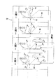
ワーク位置決め姿勢状態図作成手段20Eは、各曲げ工程ごとのワーク位置決め時におけるワークWの姿勢状態を示す図α、即ち、ワーク位置決め姿勢状態図αを作成する(図6のステップ103)。
The workpiece positioning posture state
このワーク位置決め姿勢状態図αは、例えば図4の実線で示すように、ワークWを突当10、11に突き当てて位置決めした姿勢状態を、曲げ工程1、2・・・ごとに表した図であり、一般的には、矢印で指示されるように、1つ前の曲げ工程の加工後のワークWの姿勢状態(破線)に基づいて、当該曲げ加工の加工前のワーク位置決め時におけるワークWの姿勢状態(実線)が作成される。 This workpiece positioning posture state diagram α represents, for example, the bending state of each of the bending steps 1, 2,..., As shown by the solid line in FIG. In general, as indicated by an arrow, based on the posture state (broken line) of the workpiece W after the processing in the previous bending process, the workpiece at the time of workpiece positioning before the bending processing W posture state (solid line) is created.
発光制御手段20Fは(図1)、既述した光学式安全装置1を構成する投光器2の各発光素子2A〜2Gを(図3)駆動制御し(例えばレーザ発振器を起動する)、複数の光線L1 〜L7 を受光器3側へ投光する。
The light emission control means 20F (FIG. 1) controls the driving of each light emitting
干渉度合い判断手段20Gは(図1)、前記ワーク位置決め姿勢状態図α(図4)に基づいて、ワーク位置決め時におけるワークWと複数の各光線L1 〜L7 との干渉の度合いを、各曲げ工程ごとに判断する(図6のステップ104)。 The interference degree determination means 20G (FIG. 1) determines the degree of interference between the workpiece W and the plurality of light beams L 1 to L 7 at the time of workpiece positioning based on the workpiece positioning posture state diagram α (FIG. 4). A determination is made for each bending process (step 104 in FIG. 6).
この場合、上記干渉度合い判断手段20Gは(図3)、光学式安全装置1を構成する受光器3側の各受光素子3A〜3Gからの受信データγを読み込むと共に、前記記憶手段20Cに記憶されているワーク位置決め姿勢状態図αを読み込み、受光器3が投光器2側からの光線を受光すれば、当該光線はワークWと干渉せず、受光しなければ、当該光線は、ワークWと干渉すると判断する。
In this case, the interference degree determining means 20G (FIG. 3) reads the received data γ from each of the
この場合、投光器2側からの光線が受光器3側に受光されない場合、即ち遮光される場合としては、例えばワークWにフランジFが形成されているときや(図3)、成形部(下向き又は上向きなど)が形成されているときなどがある。
In this case, when the light beam from the
そして、このような判断を、各曲げ工程1、2・・・ごとに行う(図4)。
And such a judgment is performed for every
光線有効・無効判定手段20Hは(図1)、各曲げ工程ごとに、ワークWと干渉する光線Lを無効と判定し(図6のステップ105のYES→ステップ106)、ワークWと干渉しない光線を有効と判定する(図6のステップ105のNO→ステップ110)。
The light beam validity / invalidity determining means 20H (FIG. 1) determines that the light beam L that interferes with the workpiece W is invalid for each bending step (YES in
この場合、前記干渉度合い判断手段20G側(図3)から光線有効・無効判定手段20Hへは、複数の光線L1 〜L7 のうちでどの光線がワークWと干渉し、また干渉しないかの判断結果δが、曲げ工程ごとに送られて来る。
In this case, which of the plurality of light beams L 1 to L 7 interferes with the workpiece W and does not interfere with the light beam validity / invalidity determination device 20H from the interference
従って、この判断結果δに基づいて、光線有効・無効判定手段20Hは、曲げ工程ごとに、ワークWと干渉する光線、例えば光線L3 、L4 、L5 を無効とし、他のワークWと干渉しない光線、例えば光線L1 、L2 とL6 、L7 を有効として判定する。 Therefore, based on the determination result δ, the light beam validity / invalidity determination unit 20H invalidates the light beam that interferes with the workpiece W, for example, the light beams L 3 , L 4 , and L 5 , for each bending process. Non-interfering light rays, for example, light rays L 1 , L 2 and L 6 , L 7 are determined as valid.
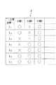
そして、判定結果εを、既述したように(図5)、各曲げ工程ごとに複数の光線のうちのどの光線が有効か無効かを明らかにした光線有効・無効判定テーブルβとして作成し、該判定テーブルβは(図3)、記憶手段20Cに記憶させておき、曲げ加工時には、後述するラム駆動制御手段20Jが、この判定テーブルβを参照ながらラム4を駆動制御する。
Then, as described above (FIG. 5), the determination result ε is created as a light beam validity / invalidity determination table β that clarifies which light beam is valid or invalid for each bending step. The determination table β (FIG. 3) is stored in the storage means 20C, and at the time of bending, the ram drive control means 20J described later drives and controls the
図5において、○は有効、×は無効をそれぞれ示し、例えば曲げ工程1においては、光線L1 、L2 とL6 、L7 が有効(○)、光線L3 〜L5 が無効(×)、曲げ工程2においては、光線L4 〜L7 が有効(○)、光線L1 〜L3 が無効(図×)、曲げ工程3では、複数の光線L1 〜L7 全部が有効(○)などが明らかにされている。
In FIG. 5, ◯ indicates effective and × indicates ineffective. For example, in the bending
ラム駆動制御手段20Jは(図1)、例えばフットペダル(図示省略)が踏まれた場合に、油圧シリンダ6、7を作動して、ラムである上部テーブル4を下降させる。
The ram drive control means 20J (FIG. 1) operates the
この場合、既述したように、ラム駆動制御手段20Jは、前記記憶手段20Cに記憶されている判定テーブルβ(図5)を参照し、若し、有効な光線が(図5の○)、作業者の手足などで遮光された場合には、ラム4(図1)を停止させるので、光学式安全装置1は機能し、作業者の安全が確保される。
In this case, as described above, the ram drive control means 20J refers to the determination table β (FIG. 5) stored in the storage means 20C, and the effective light beam (◯ in FIG. 5) When light is blocked by the worker's limbs, the ram 4 (FIG. 1) is stopped, so the
また、例えば、ラム4が下降し、パンチPがワークWと接触したとき(ピンチングポイント)、又は接触直前に(ミュートポイント(=ワークWの上ほぼ8mm程度))、該光学式安全装置1の全ての複数の光線L1 〜L7 を無効とすれば、ワークWが加工中に跳ね上がって遮光しても、光学式安全装置1は働かない。
Further, for example, when the
従って、前記ラム駆動制御手段20Jは、ラム4をD値まで下降させることができ、ワークWの曲げ加工は完了する。
Therefore, the ram drive control means 20J can lower the
以下、上記構成を有する本発明の動作を、図6に基づいて説明する。 The operation of the present invention having the above configuration will be described below with reference to FIG.
(1)シミュレーション動作(図6のステップ101〜ステップ107)。 (1) Simulation operation (step 101 to step 107 in FIG. 6).
(1)−A ワーク位置決め姿勢状態図αを作成するまでの動作。
図6のステップ101において、製品情報を入力し、ステップ102において、曲げ順などを決定し、ステップ103において、ワーク位置決め姿勢状態図αを作成する。
(1) -A Operations until the workpiece positioning posture state diagram α is created.
In
即ち、CPU20Aは(図1)、製品情報が入力されたことを検知すると、曲げ順等決定手段20Dとワーク位置決め姿勢状態図作成手段20Eを制御し、曲げ順、金型P、Dを決定させると共に、該決定された曲げ順、金型P、Dに基づいて、曲げ工程1、2・・・ごとのワーク位置決め時におけるワークWの姿勢状態を示すワーク位置決め姿勢状態図α(図4)を作成させる。
That is, when the
このワーク位置決め姿勢状態図αは、既述したように、記憶手段20C(図3)に記憶される。 The workpiece positioning posture state diagram α is stored in the storage means 20C (FIG. 3) as described above.
(1)−B 光線有効・無効判定テーブルβを作成するまでの動作。
図6のステップ104において、各曲げ工程1、2・・・ごとに、ワーク位置決め時におけるワークWと複数の各光線L1 〜L7 との干渉度合いを判断する。
(1) -B Operations until the light beam validity / invalidity determination table β is created.
6, the degree of interference between the workpiece W and the plurality of light beams L 1 to L 7 at the time of workpiece positioning is determined for each bending
即ち、前記図6のステップ103でワーク位置決め姿勢状態図αが作成されたことを検知したCPU20Aは(図1)、干渉度合い判断手段20Gを制御し、受光器3側の各受光素子3A〜3Gからの受信データγと(図3)、記憶手段20Cに記憶されているワーク位置決め姿勢状態図αを読み込ませる。
That is, the
これにより、干渉度合い判断手段20Gは、受光器3が投光器2側からの光線を受光すれば、当該光線はワークWと干渉しないと判断し、受光しなければ、当該光線は、ワークWと干渉すると判断する。
Accordingly, the interference degree determination means 20G determines that the light beam does not interfere with the workpiece W if the
そして、複数の光線L1 〜L7 のうちのどの光線がワークWと干渉し、どの光線がワークWと干渉しないかの曲げ工程1、2・・・ごとの判断結果δは、光線有効・無効判定手段20Hへ送られる。 Then, the judgment result δ for each of the bending steps 1, 2,... Of which of the plurality of rays L 1 to L 7 interferes with the workpiece W and which rays do not interfere with the workpiece W is: It is sent to the invalidity determination means 20H.
そこで、光線有効・無効判定手段20Hは、干渉度合い判断手段20G側から送られて来た判断結果δに基づいて、曲げ工程1、2・・・ごとに各光線のワークWに対する干渉・非干渉の弁別を行うことにより(図6のステップ105)、干渉すれば(図6のステップ105のYES)、当該光線を無効と判定し(図6のステップ107)、干渉しなければ(図6のステップ105のNO)、当該光線を有効と判定する(図6のステップ110)。
Therefore, the light beam validity / invalidity determination means 20H is based on the determination result δ sent from the interference degree determination means 20G side, and the interference / non-interference of each light beam with respect to the workpiece W in each of the bending steps 1, 2,. 6 (step 105 in FIG. 6), if there is interference (YES in
この判定結果ε(図3)に基づき、光線有効・無効判定手段20Hは、各曲げ工程ごとに複数の光線のうちのどの光線が有効か無効かを明らかにした光線有効・無効判定テーブルβ(図5)を作成する。 Based on this determination result ε (FIG. 3), the light beam validity / invalidity determining means 20H makes a light beam validity / invalidity determination table β () which clarifies which light beam is valid or invalid for each bending step. FIG. 5) is created.
そして、この光線有効・無効判定テーブルβも、記憶手段20C(図3)に記憶される。 The ray validity / invalidity determination table β is also stored in the storage means 20C (FIG. 3).
(3)曲げ加工動作(図6のステップ108〜ステップ109)。 (3) Bending operation (Step 108 to Step 109 in FIG. 6).
前記図6のステップ107で光線有効・無効判定テーブルβが作成されたことを検知したCPU20Aは(図1)、各手段の動作モードをシミュレーションモードから曲げ加工モードに切り換えた後、例えば入出力手段20Bの画面上にこれから曲げ加工モードに入る旨を表示して作業者に知らせる。
The
それを見た作業者は、所定の金型P、Dを上部テーブル4と下部テーブル5の所定の位置に装着すると共に、ワークWを突当10、11に突き当てて位置決めした後、フットペダル(図示省略)を踏むと、それを検知したCPU20Aは、ラム駆動制御手段20Jを介して油圧シリンダ6、7を作動し、ラム4を下降させる。
An operator who sees it attaches predetermined molds P and D to predetermined positions of the upper table 4 and the lower table 5, positions the work W against the
この場合、ラム駆動制御手段20Jは、記憶手段20Cに記憶されている判定テーブルβ(図5)を参照し、若し、有効な光線が(図5の○)、作業者の手足などで遮光されたことを光学式安全装置1を構成する受光器3を介して検知したときには、ラム4を停止させる。
In this case, the ram drive control means 20J refers to the determination table β (FIG. 5) stored in the storage means 20C, and the effective light beam (O in FIG. 5) is blocked by the operator's limbs. When this is detected via the
これにより、光学式安全装置1は機能し、作業者の安全が確保される。
Thereby, the
また、ラム4が下降することにより、パンチPがワークWと接触したとすれば(ピンチングポイント)、例えばこのときに、光学式安全装置1の全ての複数の光線L1 〜L7 が無効になるので、ワークWが加工中に跳ね上がって遮光しても、光学式安全装置1は働かず、ラム駆動制御手段20Jは、ラム4をD値まで下降させれば、該ワークWの曲げ加工は完了する(図6のステップ108)。
If the punch P comes into contact with the workpiece W by the lowering of the ram 4 (pinching point), for example, at this time, all the plurality of light beams L 1 to L 7 of the
このような曲げ加工動作が、各曲げ工程について行われ(図6のステップ109のNO→ステップ108)、全曲げ加工終了時に(図6のステップ109のYES)、動作が完了する(END)。
Such a bending operation is performed for each bending process (NO in
本発明は、光学式安全装置を有する曲げ加工装置において、各曲げ工程ごとに、複数光線のうちのワーク位置決め時に該ワークが遮光する光線を、予め無効とし、その他の光線を有効とすることにより、光学式安全装置を使用できるようにして作業者の安全を確保すると共に、曲げ工程ごとのワーク位置決め時における光線配置変更を不要にして作業効率の向上を図る曲げ加工方法及びその装置に利用され、具体的には、下降式プレスブレーキのみならず、上昇式プレスブレーキに適用され、更には、操作画面上のシミュレーションのみならず、NC装置内部でのデータ処理によるシミュレーションが可能なプレスブレーキに有用である。 The present invention provides a bending apparatus having an optical safety device, in which, for each bending step, a light beam shielded by the workpiece during positioning of the workpiece is invalidated in advance and other light beams are enabled. In addition, the optical safety device can be used to ensure the safety of the operator, and it is used in a bending method and apparatus for improving work efficiency by eliminating the need to change the arrangement of light beams at the time of workpiece positioning for each bending process. Specifically, it is applied not only to the press-down press brake but also to the press-up press brake, and also useful for press brakes that can be simulated not only on the operation screen but also by data processing inside the NC unit. It is.
1 光学式安全装置
2 投光器
2A〜2G 発光素子
3 受光器
3A〜3G 受光素子
4 上部テーブル
5 下部テーブル
6、7 油圧シリンダ
8、9 側板
10、11 突当
20 NC装置
20A CPU
20B 入出力手段
20C 記憶手段
20D 曲げ順等決定手段
20E ワーク位置決め姿勢状態図作成手段
20F 発光制御手段
20G 干渉度合い判断手段
20H 光線有効・無効判定手段
20J ラム駆動制御手段
21 上位NC装置
D ダイ
L1 〜L7 複数の光線
P パンチ
W ワーク
DESCRIPTION OF
20B I / O means 20C Storage means 20D Bending order determination means 20E Work positioning posture state diagram creation means 20F Light emission control means 20G Interference degree determination means 20H Light beam validity / invalidity determination means 20J Ram drive control means 21 Host NC device D Die L 1 ~ L 7 Multiple rays P Punch W Workpiece
Claims (4)
製品情報により決定される曲げ順、金型に基づいて、各曲げ工程ごとのワーク位置決め時におけるワークの姿勢状態を示す図を作成した後、該ワーク位置決め姿勢状態図に基づいて、ワーク位置決め時におけるワークと複数の各光線との干渉度合いを、各曲げ工程ごとに判断し、該判断結果に基づいて、各曲げ工程ごとに、ワークと干渉する光線を無効と判定することを特徴とする曲げ加工方法。 In a bending device that has an optical safety device consisting of a projector and a light receiver that stretches a plurality of light beams in front of the machine body, and bending the workpiece with a punch and die,
Based on the bending order and mold determined by the product information, after creating a diagram showing the workpiece posture at the time of workpiece positioning for each bending process, based on the workpiece positioning posture diagram at the time of workpiece positioning A bending process characterized in that the degree of interference between a workpiece and each of a plurality of light beams is determined for each bending step, and based on the determination result, the light beam that interferes with the workpiece is determined invalid for each bending step. Method.
製品情報に基づいて、曲げ順、金型を決定する曲げ順等決定手段と、
各曲げ工程ごとのワーク位置決め時におけるワークの姿勢状態を示す図を作成するワーク位置決め姿勢状態図作成手段と、
該ワーク位置決め姿勢状態図に基づいて、ワーク位置決め時におけるワークと複数の各光線との干渉度合いを、各曲げ工程ごとに判断する干渉度合い判断手段と、
該判断結果に基づいて、各曲げ工程ごとに、ワークと干渉する光線を無効と判定し、ワークと干渉しない光線を有効と判定する光線有効・無効判定手段を有することを特徴とする曲げ加工装置。 In a bending device that has an optical safety device consisting of a projector and a light receiver that stretches a plurality of light beams in front of the machine body, and bending the workpiece with a punch and die,
Based on product information, bending means, etc. for determining bending order, mold, etc.,
Workpiece positioning posture state diagram creating means for creating a diagram showing the posture state of the workpiece at the time of workpiece positioning for each bending process;
Based on the workpiece positioning posture state diagram, an interference degree determination means for determining the degree of interference between the workpiece and each of the plurality of light beams at the time of workpiece positioning for each bending step;
A bending apparatus characterized by having a light beam validity / invalidity determining means for determining that a light beam that interferes with a workpiece is invalid and validating a light beam that does not interfere with the workpiece for each bending step based on the determination result .
Priority Applications (1)
| Application Number | Priority Date | Filing Date | Title |
|---|---|---|---|
| JP2004112929A JP2005296966A (en) | 2004-04-07 | 2004-04-07 | Bending method and bending device |
Applications Claiming Priority (1)
| Application Number | Priority Date | Filing Date | Title |
|---|---|---|---|
| JP2004112929A JP2005296966A (en) | 2004-04-07 | 2004-04-07 | Bending method and bending device |
Publications (1)
| Publication Number | Publication Date |
|---|---|
| JP2005296966A true JP2005296966A (en) | 2005-10-27 |
Family
ID=35329148
Family Applications (1)
| Application Number | Title | Priority Date | Filing Date |
|---|---|---|---|
| JP2004112929A Pending JP2005296966A (en) | 2004-04-07 | 2004-04-07 | Bending method and bending device |
Country Status (1)
| Country | Link |
|---|---|
| JP (1) | JP2005296966A (en) |
Cited By (7)
| Publication number | Priority date | Publication date | Assignee | Title |
|---|---|---|---|---|
| JP2006116574A (en) * | 2004-10-22 | 2006-05-11 | Amada Co Ltd | Bending method, and its apparatus |
| JP2007175716A (en) * | 2005-12-27 | 2007-07-12 | Amada Co Ltd | Bending apparatus |
| JP2016147358A (en) * | 2015-02-13 | 2016-08-18 | 株式会社プリントパック | Cutting machine |
| WO2017179355A1 (en) * | 2016-04-14 | 2017-10-19 | 株式会社アマダホールディングス | Safety device for press brake and control method for press brake |
| JP2018051603A (en) * | 2016-09-29 | 2018-04-05 | 株式会社アマダホールディングス | Press brake and workpiece presence / absence judgment method |
| WO2018163525A1 (en) * | 2017-03-08 | 2018-09-13 | 株式会社アマダホールディングス | Press brake |
| WO2019176924A1 (en) * | 2018-03-14 | 2019-09-19 | 株式会社アマダホールディングス | Optical safety device for press brakes, press brake, and optical monitoring method |
-
2004
- 2004-04-07 JP JP2004112929A patent/JP2005296966A/en active Pending
Cited By (15)
| Publication number | Priority date | Publication date | Assignee | Title |
|---|---|---|---|---|
| JP2006116574A (en) * | 2004-10-22 | 2006-05-11 | Amada Co Ltd | Bending method, and its apparatus |
| JP2007175716A (en) * | 2005-12-27 | 2007-07-12 | Amada Co Ltd | Bending apparatus |
| JP2016147358A (en) * | 2015-02-13 | 2016-08-18 | 株式会社プリントパック | Cutting machine |
| KR101942889B1 (en) | 2016-04-14 | 2019-01-28 | 가부시키가이샤 아마다 홀딩스 | Safety device of press brake and control method of press brake |
| JP2017189800A (en) * | 2016-04-14 | 2017-10-19 | 株式会社アマダホールディングス | Safety device of press brake and control method of press brake |
| CN109070168A (en) * | 2016-04-14 | 2018-12-21 | 株式会社天田控股集团 | The safety device of bending machine and the control method of bending machine |
| WO2017179355A1 (en) * | 2016-04-14 | 2017-10-19 | 株式会社アマダホールディングス | Safety device for press brake and control method for press brake |
| US10369607B2 (en) | 2016-04-14 | 2019-08-06 | Amada Holdings Co., Ltd. | Safety device of press brake and controlling method of press brake |
| CN109070168B (en) * | 2016-04-14 | 2019-08-23 | 株式会社天田控股集团 | Safety device of bending machine |
| JP2018051603A (en) * | 2016-09-29 | 2018-04-05 | 株式会社アマダホールディングス | Press brake and workpiece presence / absence judgment method |
| WO2018163525A1 (en) * | 2017-03-08 | 2018-09-13 | 株式会社アマダホールディングス | Press brake |
| JP2018144090A (en) * | 2017-03-08 | 2018-09-20 | 株式会社アマダホールディングス | Press brake |
| WO2019176924A1 (en) * | 2018-03-14 | 2019-09-19 | 株式会社アマダホールディングス | Optical safety device for press brakes, press brake, and optical monitoring method |
| JP2019155433A (en) * | 2018-03-14 | 2019-09-19 | 株式会社アマダホールディングス | Optical type safety device for press break, press brake, and optical type monitoring method |
| US11623267B2 (en) | 2018-03-14 | 2023-04-11 | Amada Co., Ltd. | Optical safety device for press brake, press brake, and optical monitoring method |
Similar Documents
| Publication | Publication Date | Title |
|---|---|---|
| JP5856860B2 (en) | Plate workpiece processing apparatus and workpiece positioning support method | |
| JP2005296966A (en) | Bending method and bending device | |
| US7818985B2 (en) | Bending apparatus | |
| JP4743688B2 (en) | Bending machine | |
| JP2009106972A (en) | Bending machine | |
| JP4674885B2 (en) | Bending apparatus and method | |
| JP4565633B2 (en) | Bending machine | |
| JP4493463B2 (en) | Bending method and apparatus | |
| ITPN980075A1 (en) | DEVICE TO AVOID ACCIDENTS TO THE OPERATOR OF A BENDER | |
| JP3908103B2 (en) | Bending machine | |
| JP4397017B2 (en) | Bending machine | |
| JP2006061959A (en) | Press brake | |
| JP6812184B2 (en) | Press brake and work presence / absence determination method | |
| JP3668895B1 (en) | Bending method and apparatus | |
| JP2003275820A (en) | Optical safety device, optical axis aligning jig, device and method | |
| JP2003181542A (en) | Bending device | |
| JP2021016868A (en) | Machine tool system and tool exchange method | |
| JP2006297469A (en) | Bending device | |
| JP2007069262A (en) | Bending machine | |
| JP2006297424A (en) | Method and device for positioning workpiece in bending | |
| JP4798905B2 (en) | Bending machine | |
| JP2006346705A (en) | Bending apparatus and its method | |
| JP2002079315A (en) | Bending machine | |
| JP2006305609A (en) | Bending apparatus | |
| JP2006122956A (en) | Bending apparatus |
Legal Events
| Date | Code | Title | Description |
|---|---|---|---|
| A621 | Written request for application examination |
Free format text: JAPANESE INTERMEDIATE CODE: A621 Effective date: 20070322 |
|
| A521 | Written amendment |
Free format text: JAPANESE INTERMEDIATE CODE: A523 Effective date: 20070418 |
|
| A977 | Report on retrieval |
Free format text: JAPANESE INTERMEDIATE CODE: A971007 Effective date: 20090508 |
|
| A131 | Notification of reasons for refusal |
Free format text: JAPANESE INTERMEDIATE CODE: A131 Effective date: 20090513 |
|
| A521 | Written amendment |
Free format text: JAPANESE INTERMEDIATE CODE: A523 Effective date: 20090711 |
|
| A02 | Decision of refusal |
Free format text: JAPANESE INTERMEDIATE CODE: A02 Effective date: 20100115 |