JP2009091921A - Catalyst deterioration diagnosis device for internal combustion engine - Google Patents
Catalyst deterioration diagnosis device for internal combustion engine Download PDFInfo
- Publication number
- JP2009091921A JP2009091921A JP2007261235A JP2007261235A JP2009091921A JP 2009091921 A JP2009091921 A JP 2009091921A JP 2007261235 A JP2007261235 A JP 2007261235A JP 2007261235 A JP2007261235 A JP 2007261235A JP 2009091921 A JP2009091921 A JP 2009091921A
- Authority
- JP
- Japan
- Prior art keywords
- catalyst
- air
- fuel ratio
- oxygen storage
- storage capacity
- Prior art date
- Legal status (The legal status is an assumption and is not a legal conclusion. Google has not performed a legal analysis and makes no representation as to the accuracy of the status listed.)
- Pending
Links
Images


Classifications
-
- Y—GENERAL TAGGING OF NEW TECHNOLOGICAL DEVELOPMENTS; GENERAL TAGGING OF CROSS-SECTIONAL TECHNOLOGIES SPANNING OVER SEVERAL SECTIONS OF THE IPC; TECHNICAL SUBJECTS COVERED BY FORMER USPC CROSS-REFERENCE ART COLLECTIONS [XRACs] AND DIGESTS
- Y02—TECHNOLOGIES OR APPLICATIONS FOR MITIGATION OR ADAPTATION AGAINST CLIMATE CHANGE
- Y02T—CLIMATE CHANGE MITIGATION TECHNOLOGIES RELATED TO TRANSPORTATION
- Y02T10/00—Road transport of goods or passengers
- Y02T10/10—Internal combustion engine [ICE] based vehicles
- Y02T10/12—Improving ICE efficiencies
-
- Y—GENERAL TAGGING OF NEW TECHNOLOGICAL DEVELOPMENTS; GENERAL TAGGING OF CROSS-SECTIONAL TECHNOLOGIES SPANNING OVER SEVERAL SECTIONS OF THE IPC; TECHNICAL SUBJECTS COVERED BY FORMER USPC CROSS-REFERENCE ART COLLECTIONS [XRACs] AND DIGESTS
- Y02—TECHNOLOGIES OR APPLICATIONS FOR MITIGATION OR ADAPTATION AGAINST CLIMATE CHANGE
- Y02T—CLIMATE CHANGE MITIGATION TECHNOLOGIES RELATED TO TRANSPORTATION
- Y02T10/00—Road transport of goods or passengers
- Y02T10/10—Internal combustion engine [ICE] based vehicles
- Y02T10/40—Engine management systems
Abstract
Description
本発明は、内燃機関の排気通路に配置された触媒の劣化を診断する装置に関する。 The present invention relates to an apparatus for diagnosing deterioration of a catalyst disposed in an exhaust passage of an internal combustion engine.
例えば車両用の内燃機関において、その排気系には排気ガスを浄化するための触媒が設置されている。この触媒の中には酸素吸蔵能(O2ストレージ能)を有するものがあり、これは、触媒に流入する排気ガスの空燃比が理論空燃比(ストイキ)よりも大きくなると、即ちリーンになると排気ガス中に存在する過剰酸素を吸着保持し、触媒流入排気ガスの空燃比がストイキよりも小さくなると、即ちリッチになると吸着保持された酸素を放出する。例えばガソリンエンジンでは触媒に流入する排気ガスがストイキ近傍となるよう空燃比制御が行われるが、酸素吸蔵能を有する三元触媒を使用すると、運転条件により実際の空燃比がストイキから多少振れてしまっても、三元触媒による酸素の吸蔵・放出作用により、そのような空燃比ずれを吸収することができる。 For example, in an internal combustion engine for a vehicle, a catalyst for purifying exhaust gas is installed in the exhaust system. Some of these catalysts have an oxygen storage capacity (O 2 storage capacity). This is because when the air-fuel ratio of the exhaust gas flowing into the catalyst becomes larger than the stoichiometric air-fuel ratio (stoichiometric), that is, the exhaust gas becomes lean. Excess oxygen present in the gas is adsorbed and held, and when the air-fuel ratio of the catalyst inflow exhaust gas becomes smaller than the stoichiometric, that is, becomes rich, the adsorbed and held oxygen is released. For example, in a gasoline engine, air-fuel ratio control is performed so that the exhaust gas flowing into the catalyst is in the vicinity of the stoichiometric. However, such an air-fuel ratio shift can be absorbed by the oxygen storage / release action of the three-way catalyst.
ところで、触媒が劣化すると触媒の浄化効率が低下する。一方、触媒の劣化度と酸素吸蔵能の低下度との間にはともに貴金属を介する反応であるため相関関係がある。よって、酸素吸蔵能が低下したことを検出することで触媒が劣化したことを検出することができる。一般的には、触媒に流入する排気ガスの空燃比を強制的にリッチ及びリーンに切り替えるアクティブ空燃比制御を行い、このアクティブ空燃比制御の実行に伴って触媒の酸素吸蔵容量を計測し、触媒の劣化を診断する方法(所謂Cmax法)が採用される(特許文献1等参照)。
By the way, when the catalyst deteriorates, the purification efficiency of the catalyst decreases. On the other hand, there is a correlation between the degree of deterioration of the catalyst and the degree of reduction of the oxygen storage capacity because they are reactions through noble metals. Therefore, it is possible to detect that the catalyst has deteriorated by detecting that the oxygen storage capacity has decreased. In general, active air-fuel ratio control for forcibly switching the air-fuel ratio of the exhaust gas flowing into the catalyst to rich and lean is performed, and the oxygen storage capacity of the catalyst is measured as the active air-fuel ratio control is executed. A method (so-called Cmax method) for diagnosing deterioration of the ink is employed (see
一方、近年では、吸気弁の作用角(開弁角)を機関運転状態に応じて連続的に可変とする可変動弁装置が開発されるに至っている。こうした可変動弁装置を備える内燃機関では、吸気弁の作用角を変化させることで、燃焼室内に吸入される空気量を全運転域に亘って変化させることができる。よってスロットル開度を通常より開いたり、或いは省略することもでき、これによってポンピングロスを減少し、同一の出力をより少ない空気量及び燃料量で得られ、燃費を向上することができる。 On the other hand, in recent years, variable valve gears have been developed in which the operating angle (opening angle) of the intake valve is continuously variable according to the engine operating state. In an internal combustion engine equipped with such a variable valve device, the amount of air taken into the combustion chamber can be changed over the entire operating range by changing the operating angle of the intake valve. Therefore, the throttle opening can be opened or omitted more than usual, thereby reducing the pumping loss, the same output can be obtained with a smaller amount of air and fuel, and fuel efficiency can be improved.
かかる可変動弁装置を備える内燃機関において触媒の劣化を診断する場合、吸気弁の作用角の違いにより、他の条件がほぼ同じであっても酸素吸蔵能の計測値が変化することが判明した。よって、このような吸気弁の作用角の違いを考慮に入れないと、酸素吸蔵能の計測値のみならず診断結果自体の精度や信頼性を損なってしまう。 When diagnosing catalyst deterioration in an internal combustion engine equipped with such a variable valve system, it has been found that the measured value of the oxygen storage capacity changes due to the difference in the operating angle of the intake valve even if other conditions are substantially the same. . Therefore, unless such a difference in the operating angle of the intake valve is taken into consideration, not only the measured value of the oxygen storage capacity but also the accuracy and reliability of the diagnostic result itself are impaired.
そこで本発明は、かかる事情に鑑みて創案されたものであり、その目的は、吸気弁の作用角を可変制御する内燃機関において、触媒劣化診断の精度及び信頼性を向上することができる内燃機関の触媒劣化診断装置を提供することにある。 Accordingly, the present invention has been made in view of such circumstances, and an object of the present invention is to improve the accuracy and reliability of catalyst deterioration diagnosis in an internal combustion engine that variably controls the operating angle of an intake valve. An object of the present invention is to provide a catalyst deterioration diagnosis apparatus.
本発明の一形態によれば、
内燃機関の排気通路に配置された触媒の劣化を診断する装置であって、
前記触媒の温度を推定する触媒温度推定手段と、
前記触媒の酸素吸蔵能を計測し、この計測された酸素吸蔵能を触媒温度に基づき補正し、この補正後の酸素吸蔵能に基づき前記触媒の劣化を診断する診断手段と、
吸気弁の作用角を可変制御する吸気弁可変制御手段と、
前記作用角に基づき、前記触媒温度推定手段によって推定された触媒温度を補正する触媒温度補正手段と
を備えたことを特徴とする内燃機関の触媒劣化診断装置が提供される。
According to one aspect of the invention,
An apparatus for diagnosing deterioration of a catalyst disposed in an exhaust passage of an internal combustion engine,
Catalyst temperature estimating means for estimating the temperature of the catalyst;
Diagnostic means for measuring the oxygen storage capacity of the catalyst, correcting the measured oxygen storage capacity based on the catalyst temperature, and diagnosing deterioration of the catalyst based on the corrected oxygen storage capacity;
Intake valve variable control means for variably controlling the operating angle of the intake valve;
There is provided a catalyst deterioration diagnosis device for an internal combustion engine, comprising: catalyst temperature correction means for correcting the catalyst temperature estimated by the catalyst temperature estimation means based on the operating angle.
本発明者らの試験研究の結果によれば、作用角の違いにより触媒温度が変化することが判明した。そこで本発明の一形態においては、推定された触媒温度を作用角に基づいて補正することとしている。こうすることで作用角の違いを考慮し、触媒温度の推定ズレを抑制することができる。そして最終的に正確な触媒温度補正後の酸素吸蔵能を得、触媒劣化診断の精度及び信頼性を向上することができる。 According to the results of the study by the inventors, it has been found that the catalyst temperature changes due to the difference in the working angle. Therefore, in one embodiment of the present invention, the estimated catalyst temperature is corrected based on the operating angle. By doing so, it is possible to suppress the estimated deviation of the catalyst temperature in consideration of the difference in the operating angle. And finally, the oxygen storage capacity after correct | amending catalyst temperature exact can be obtained, and the precision and reliability of a catalyst deterioration diagnosis can be improved.
好ましくは、前記内燃機関の吸入空気量を検出する吸入空気量検出手段を備え、前記触媒温度推定手段が、前記吸入空気量検出手段により検出された吸入空気量に基づいて前記触媒温度を推定する。 Preferably, an intake air amount detection means for detecting an intake air amount of the internal combustion engine is provided, and the catalyst temperature estimation means estimates the catalyst temperature based on the intake air amount detected by the intake air amount detection means. .
本発明の他の形態によれば、
内燃機関の排気通路に配置された触媒の劣化を診断する装置であって、
前記触媒の温度を計測する触媒温度計測手段と、
前記触媒の酸素吸蔵能を計測し、この計測された酸素吸蔵能を触媒温度に基づき補正し、この補正後の酸素吸蔵能に基づき前記触媒の劣化を診断する診断手段と、
吸気弁の作用角を可変制御する吸気弁可変制御手段と、
内燃機関の吸気通路に配置されたスロットルバルブの開度を制御するスロットルバルブ制御手段と、
前記内燃機関の点火時期を制御する点火時期制御手段と、
を備え、
前記触媒の劣化診断時、前記吸気弁可変制御手段が前記吸気弁の作用角を通常時よりも減少し、前記スロットルバルブ制御手段が前記スロットルバルブ開度を通常時よりも増加し、且つ、前記点火時期制御手段が前記点火時期を通常時よりも遅角する
ことを特徴とする内燃機関の触媒劣化診断装置が提供される。
According to another aspect of the invention,
An apparatus for diagnosing deterioration of a catalyst disposed in an exhaust passage of an internal combustion engine,
Catalyst temperature measuring means for measuring the temperature of the catalyst;
Diagnostic means for measuring the oxygen storage capacity of the catalyst, correcting the measured oxygen storage capacity based on the catalyst temperature, and diagnosing deterioration of the catalyst based on the corrected oxygen storage capacity;
Intake valve variable control means for variably controlling the operating angle of the intake valve;
Throttle valve control means for controlling the opening of a throttle valve disposed in the intake passage of the internal combustion engine;
Ignition timing control means for controlling the ignition timing of the internal combustion engine;
With
At the time of diagnosis of deterioration of the catalyst, the intake valve variable control means decreases the operating angle of the intake valve from the normal time, the throttle valve control means increases the throttle valve opening from the normal time, and the An apparatus for diagnosing catalyst deterioration in an internal combustion engine is provided in which the ignition timing control means retards the ignition timing from the normal time.
作用角を始めとした各パラメータのバラツキにより酸素吸蔵能の計測値は変化するが、このときできるだけ大きな計測値を得るようにすると、バラツキ影響が少なくなって高精度の計測及び診断に有利である。こうするには、できるだけ高い触媒温度条件の下で計測及び診断をするのが有効である。ところで、エンジン出力トルクが一定の場合、作用角を小さくし、スロットル開度を増加し、且つ点火時期を遅角すると、触媒温度が上昇する。つまり、作用角を小さくしてスロットル開度を増加すると、これによりポンピングロスが減少し、トルクが増大する。そしてこのトルク増大分だけ点火時期を遅角すると、燃焼室から排出される排気ガス中に未燃成分が増え、これが触媒中で燃焼して触媒温度が上昇する。よって本発明の他の形態のように、触媒の劣化診断時、吸気弁の作用角を通常時よりも減少し、スロットルバルブ開度を通常時よりも増加し、且つ、点火時期を通常時よりも遅角することで、触媒温度を上昇させ、酸素吸蔵能計測値を増大して精度向上を図れる。 The measured value of oxygen storage capacity varies depending on the variation of each parameter including the working angle, but if the largest possible measured value is obtained at this time, the variation effect is reduced and it is advantageous for high-precision measurement and diagnosis. . For this purpose, it is effective to perform measurement and diagnosis under as high a catalyst temperature condition as possible. By the way, when the engine output torque is constant, the catalyst temperature rises when the operating angle is reduced, the throttle opening is increased, and the ignition timing is retarded. That is, when the operating angle is reduced and the throttle opening is increased, the pumping loss is thereby reduced and the torque is increased. When the ignition timing is retarded by this torque increase, unburned components increase in the exhaust gas exhausted from the combustion chamber, which burns in the catalyst and raises the catalyst temperature. Therefore, as in other embodiments of the present invention, when diagnosing catalyst deterioration, the operating angle of the intake valve is decreased from the normal time, the throttle valve opening is increased from the normal time, and the ignition timing is set from the normal time. However, it is possible to improve the accuracy by increasing the catalyst temperature and increasing the oxygen storage capacity measurement value.
好ましくは、前記触媒の劣化診断時、前記作用角が所定の下限値以上になるように前記吸気弁可変制御手段が前記作用角を制御する。 Preferably, at the time of the deterioration diagnosis of the catalyst, the intake valve variable control means controls the operating angle so that the operating angle is equal to or greater than a predetermined lower limit value.
吸気弁作用角が可変の内燃機関の場合、気筒毎の作用角のばらつきにより、気筒毎の空燃比がずれて実際の中心空燃比が目標値からずれてしまう場合があり、このずれは作用角が小さいほど現れやすい。そして本発明の他の形態では、劣化診断時に作用角を減少するので、こういった中心空燃比のずれ、ひいてはこれに起因する酸素吸蔵能計測値のずれが起こり易い。そこで、作用角が所定の下限値以上になるように作用角を制御する。こうすることで、顕著な中心空燃比のずれが生じるほどに作用角を減少してしまうのを防止し、中心空燃比のずれに起因する酸素吸蔵能計測値のずれを防止することができる。そして結果的に高精度で信頼性の高い診断結果を得ることができる。 In the case of an internal combustion engine having a variable intake valve working angle, the air-fuel ratio of each cylinder may deviate and the actual center air-fuel ratio deviates from the target value due to variations in the working angle of each cylinder. The smaller the is, the more likely it is to appear. In another embodiment of the present invention, since the operating angle is reduced at the time of deterioration diagnosis, such a deviation of the central air-fuel ratio, and thus a deviation of the measured value of the oxygen storage capacity, is likely to occur. Therefore, the operating angle is controlled so that the operating angle is equal to or greater than a predetermined lower limit value. By doing so, it is possible to prevent the operating angle from being reduced to such an extent that a significant shift in the center air-fuel ratio occurs, and it is possible to prevent a shift in the oxygen storage capacity measurement value caused by the shift in the center air-fuel ratio. As a result, a highly accurate and reliable diagnosis result can be obtained.
本発明によれば、吸気弁の作用角を可変制御する内燃機関において、触媒劣化診断の精度及び信頼性を向上することができるという、優れた効果が発揮される。 According to the present invention, in the internal combustion engine that variably controls the working angle of the intake valve, an excellent effect that the accuracy and reliability of the catalyst deterioration diagnosis can be improved is exhibited.
以下、本発明を実施するための最良の形態を添付図面に基づき説明する。 The best mode for carrying out the present invention will be described below with reference to the accompanying drawings.
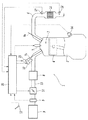
図1は、本実施形態の構成を示す概略図である。図示されるように、内燃機関1は、シリンダブロック2に形成された燃焼室3の内部で燃料および空気の混合気を燃焼させ、燃焼室3内でピストン4を往復移動させることにより動力を発生する。内燃機関1は車両に搭載された多気筒エンジン(1気筒のみ図示)であり、火花点火式内燃機関、より具体的にはガソリンエンジンである。
FIG. 1 is a schematic diagram showing the configuration of the present embodiment. As shown in the figure, the
内燃機関1のシリンダヘッドには、吸気ポートを開閉する吸気弁Viと、排気ポートを開閉する排気弁Veとが気筒ごとに配設されている。各吸気弁Viおよび各排気弁Veは図示しないカムシャフトによって開閉させられる。また、シリンダヘッドの頂部には、燃焼室3内の混合気に点火するための点火プラグ7が気筒ごとに取り付けられている。
In the cylinder head of the
各気筒の吸気ポートは気筒毎の枝管を介して吸気集合室であるサージタンク8に接続されている。サージタンク8の上流側には吸気集合通路をなす吸気管13が接続されており、吸気管13の上流端にはエアクリーナ9が設けられている。そして吸気管13には、上流側から順に、吸入空気量を検出するためのエアフローメータ5と、電子制御式スロットルバルブ10とが組み込まれている。なお吸気ポート、サージタンク8及び吸気管13により吸気通路が形成される。
The intake port of each cylinder is connected to a surge tank 8 serving as an intake air collecting chamber via a branch pipe for each cylinder. An
吸気通路、特に吸気ポート内に燃料を噴射するインジェクタ(燃料噴射弁)12が気筒ごとに配設される。インジェクタ12から噴射された燃料は吸入空気と混合されて混合気をなし、この混合気が吸気弁Viの開弁時に燃焼室3に吸入され、ピストン4で圧縮され、点火プラグ7で点火燃焼させられる。
An injector (fuel injection valve) 12 that injects fuel into the intake passage, particularly into the intake port, is provided for each cylinder. The fuel injected from the
一方、各気筒の排気ポートは気筒毎の枝管を介して排気集合通路をなす排気管6に接続されており、排気管6には、O2ストレージ機能(酸素吸蔵能)を有する三元触媒からなる触媒11が取り付けられている。なお排気ポート、枝管及び排気管6により排気通路が形成される。触媒11の上流側と下流側とにそれぞれ、排気中の酸素濃度に基づいて排気空燃比を検出する空燃比センサ、即ち触媒前センサ17及び触媒後センサ18が設置されている。触媒前センサ17は所謂広域空燃比センサからなり、比較的広範囲に亘る空燃比を連続的に検出可能で、排気空燃比に比例した値の信号を出力する。他方、触媒後センサ18は所謂O2センサからなり、理論空燃比を境に出力値が急変する特性を持つ。
On the other hand, the exhaust port of each cylinder is connected to an
上述の点火プラグ7、スロットルバルブ10及びインジェクタ12等は、制御手段としての電子制御ユニット(以下ECUと称す)20に電気的に接続されている。ECU20は、何れも図示されないCPU、ROM、RAM、入出力ポート、および記憶装置等を含むものである。またECU20には、図示されるように、前述のエアフローメータ5、触媒前センサ17、触媒後センサ18のほか、内燃機関1のクランク角を検出するクランク角センサ14、アクセル開度を検出するアクセル開度センサ15、その他の各種センサが図示されないA/D変換器等を介して電気的に接続されている。ECU20は、各種センサの検出値等に基づいて、所望の出力が得られるように、点火プラグ7、スロットルバルブ10、インジェクタ12等を制御し、点火時期、燃料噴射量、燃料噴射時期、スロットル開度等を制御する。
The spark plug 7, the
吸気カムシャフトと吸気弁Viとの間には、吸気弁Viの作用角α、即ち吸気弁Viが開いているクランク角度である開弁角を可変とする可変機構21が設けられている。吸気弁Viの作用角αは、ECU20からの指令信号に基づく可変機構21の駆動を通じて可変制御される。
A
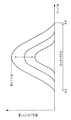
可変機構21による作用角の変更態様を図2に示す。同図に示す特性曲線から分かるように、吸気弁Viの作用角αはその最大リフト量Limaxと同期して連続的に変化する。例えば作用角αが小さくなるほど最大リフト量Limaxも小さくなる。作用角αが小さくなるということは、吸気弁Viの開弁時期と閉弁時期とが互いに接近するということであり、吸気弁Viの開弁期間が短くなるということでもある。本実施形態では、ある一定のクランク角で常に最大リフト量Limaxとなり、この最大リフト量クランク角を中心に作用角αが増減し、開閉タイミングも変化する特性となっている。しかしながら、吸気弁の可変特性はここで説明されたものに限定されない。
FIG. 2 shows how the operating angle is changed by the
本実施形態では、燃焼室3に吸入される空気量の調節が、吸気弁Viの作用角αと共にスロットルバルブ10の開度(スロットル開度)THを調節或いは制御することで行われる。即ち、吸気弁Viの作用角αの制御のみによっても吸入空気量の制御が可能であるが、本実施形態ではそれと併せてスロットル開度THも制御するようにしている。一定のエンジン出力トルクを得ようとした場合、可変機構21の無い通常のエンジンの如くスロットル開度のみを制御するよりは、本実施形態の如く吸気弁作用角及びスロットル開度を協調制御した方が、スロットル開度を大きく開き側に設定することができる。よってスロットル開度を増加した分、ポンピングロスを低減することができ、必要な空気量及び燃料量が抑えられて燃費を向上することができる。なお、本実施形態のような可変機構21を設けると、吸気弁作用角の制御のみでも吸入空気量が全域制御可能になるため、スロットルバルブ10を省略することもできる。
In the present embodiment, the amount of air taken into the
これら吸気弁作用角α及びスロットル開度THの制御を含むエンジン制御の一例を述べる。この制御はECU20によって実行される。まず、アクセル開度センサ15で検出されたアクセル開度Acに基づき、予め設定されたマップ(関数でもよい、以下同様)に従って、吸気弁作用角α及びスロットル開度THの目標値αtrg、THtrgが算出される。そしてこれら目標値αtrg、THtrgに実際値が一致するように吸気弁作用角α及びスロットル開度THが制御される。吸気弁作用角α及びスロットル開度THの実際値は、可変機構21及びスロットルバルブ10にそれぞれ設けられたセンサ(図示せず)で検出される。こうして吸気弁作用角α及びスロットル開度THが制御されると、実際の吸入空気量Ga及びエンジン回転速度Neがそれら吸気弁作用角α及びスロットル開度THに対応した値となる。実際の吸入空気量Ga及びエンジン回転速度Neはそれぞれエアフローメータ5及びクランク角センサ14の出力に基づき検出される。これら実際の吸入空気量Ga及びエンジン回転速度Neに基づき、予め設定されたマップに従って、点火時期、燃料噴射量及び燃料噴射時期がそれぞれ制御される。
An example of engine control including control of the intake valve working angle α and the throttle opening TH will be described. This control is executed by the
ここで、可変機構21の無い通常のエンジンと可変機構21のある本実施形態のエンジンとを比較する。例えば車両が100km/hで定常走行しており、このとき通常のエンジンだと30という値のスロットル開度であると仮定する。このとき、本実施形態のエンジンではそれより大きい例えば40という値のスロットル開度に制御され、その一方で吸気弁作用角αは30或いはそれ以下のスロットル開度相当の角度に制御される。このように本実施形態のエンジンの場合、通常のエンジンの場合と比較して、エンジン出力トルクが同一ながらスロットル開度は増大され、これによりポンピングロスが低減し燃費向上が図られる。
Here, the normal engine without the
一方、触媒11は、これに流入する排気ガスの空燃比A/Fが理論空燃比(ストイキ、例えばA/Fs=14.6)近傍のときにNOx ,HCおよびCOを同時に浄化する。そしてこれに対応して、ECU20は、通常時、触媒11に流入する排気ガスの空燃比即ち触媒前空燃比A/Ffrが理論空燃比に一致するように空燃比を制御する。具体的にはECU20は、理論空燃比に等しい目標空燃比A/Ftを設定すると共に、触媒前センサ17により検出された触媒前空燃比A/Ffrが目標空燃比A/Ftに一致するように、インジェクタ12から噴射される燃料噴射量、ひいては空燃比をフィードバック制御する。このように、触媒前センサ17により検出された触媒前空燃比A/Ffrを理論空燃比に一致するようにする制御をメイン空燃比制御という。
On the other hand, the
またECU20は、通常時、触媒11から流出した排気ガスの空燃比、即ち触媒後センサ18により検出された触媒後空燃比A/Frrが理論空燃比に一致するように空燃比を制御する。この制御をサブ空燃比制御という。メイン空燃比制御を実行していても、触媒前センサ17の製品バラツキや劣化等により実際の中心空燃比が理論空燃比からずれる場合があるので、このずれを補正する目的でサブ空燃比制御が同時に行われる。メイン空燃比制御が極めて短い時間周期で実行されるのに対し、サブ空燃比制御は比較的長い時間周期で実行される。サブ空燃比制御の補正量はその長い時間周期毎に更新されていく。
Further, the
ここで、触媒11についてより詳細に説明する。図3に示すように、触媒11においては、図示しない担体基材の表面上にコート材31が被覆され、このコート材31に微粒子状の触媒成分32が多数分散配置された状態で保持され、触媒11内部で露出されている。触媒成分32は主にPt,Pd等の貴金属からなり、NOx ,HCおよびCOといった排ガス成分を反応させる際の活性点となる。他方、コート材31は、排気ガスと触媒成分32との界面における反応を促進させる助触媒の役割を担うと共に、雰囲気ガスの空燃比に応じて酸素を吸収放出可能な酸素吸蔵成分を含む。酸素吸蔵成分は例えば酸化セリウムCeO2やジルコニアからなる。例えば、触媒成分32及びコート材31の雰囲気ガスが理論空燃比よりリッチであると、触媒成分32の周囲に存在する酸素吸蔵成分に吸蔵されていた酸素が放出され、この結果、放出された酸素によりHCおよびCOといった未燃成分が酸化され、浄化される。逆に、触媒成分32及びコート材31の雰囲気ガスが理論空燃比よりリーンであると、触媒成分32の周囲に存在する酸素吸蔵成分が雰囲気ガスから酸素を吸収し、この結果NOxが還元浄化される。
Here, the
このような酸素吸放出作用により、通常の空燃比制御の際に触媒前空燃比A/Ffrが理論空燃比に対し多少ばらついたとしても、NOx、HCおよびCOといった三つの排気ガス成分を同時浄化することができる。よって通常の空燃比制御において、触媒前空燃比A/Ffrを敢えて理論空燃比を中心に微小振動させ、酸素の吸放出を繰り返させることにより排ガス浄化を行うことも可能である。 By such an oxygen absorption / release action, even if the pre-catalyst air-fuel ratio A / Ffr slightly varies from the stoichiometric air-fuel ratio during normal air-fuel ratio control, three exhaust gas components such as NOx, HC and CO are simultaneously purified. can do. Therefore, in normal air-fuel ratio control, it is also possible to purify the exhaust gas by making the pre-catalyst air-fuel ratio A / Ffr oscillate minutely around the theoretical air-fuel ratio and repeating the absorption and release of oxygen.
ところで、新品状態の触媒11では前述したように細かい粒子状の触媒成分32が多数均等に分散配置されており、排気ガスと触媒成分32との接触確率が高い状態に維持されている。しかしながら、触媒11が劣化してくると、一部の触媒成分32に消失が見られるほか、触媒成分32同士が排気熱で焼き固まって焼結状態になるものがある(図の破線参照)。こうなると排気ガスと触媒成分32との接触確率の低下を引き起こし、浄化率を落としめる原因となる。そしてこのほかに、触媒成分32の周囲に存在するコート材31の量、即ち酸素吸蔵成分の量が減少し、酸素吸蔵能自体が低下する。
By the way, in the
このように、触媒11の劣化度と触媒11の持つ酸素吸蔵能の低下度とは相関関係にある。そこで本実施形態では、触媒11の酸素吸蔵能を計測或いは検出することにより触媒11の劣化度を検出することとしている。ここで、触媒11の酸素吸蔵能は、現状の触媒11が吸蔵し得る最大酸素量である酸素吸蔵容量(OSC;O2 Strage Capacity、単位はg)の大きさによって表される。
Thus, the degree of deterioration of the
以下、本実施形態における触媒劣化診断について説明する。 Hereinafter, the catalyst deterioration diagnosis in the present embodiment will be described.
本実施形態の触媒劣化診断は前述のCmax法によるものを基本とする。そして触媒11の劣化診断に際しては、ECU20によりアクティブ空燃比制御が実行される。アクティブ空燃比制御において、混合気の空燃比ひいては触媒前空燃比A/Ffrは、所定の中心空燃比A/Fcを境にリッチ側及びリーン側に強制的に(アクティブに)交互に切り替えられる。なおリッチ側に変化されたときの空燃比をリッチ空燃比A/Fr、リーン側に変化されたときの空燃比をリーン空燃比A/Flと称す。このアクティブ空燃比制御によって触媒前空燃比A/Ffrがリッチ側又はリーン側に変化されているときに触媒の酸素吸蔵容量OSCが計測される。
The catalyst deterioration diagnosis of the present embodiment is basically based on the Cmax method described above. When the deterioration diagnosis of the
触媒11の劣化診断は、内燃機関1の定常運転時で且つ触媒11が活性温度域にあるときに実行される。触媒11の温度(触媒床温)の計測については、温度センサを用いて直接検出してもよいが、本実施形態の場合内燃機関の運転状態から推定することとしている。例えばECU20は、エアフローメータ5によって検出される吸入空気量Gaに基づいて、予め設定されたマップを利用し、触媒11の温度Tcを推定する。なお、吸入空気量Ga以外のパラメータ、例えばエンジン回転速度Ne(rpm)などを触媒温度推定に用いるパラメータに含めてもよい。
The deterioration diagnosis of the
図4(A),(B)にはそれぞれ、アクティブ空燃比制御実行時における触媒前センサ17及び触媒後センサ18の出力が実線で示されている。また、図4(A)には、ECU20内部で発生される目標空燃比A/Ftが破線で示されている。触媒前センサ17及び触媒後センサ18の出力値はそれぞれ触媒前空燃比A/Ffr及び触媒後空燃比A/Frrの値に対応する。
4A and 4B, the outputs of the
図4(A)に示されるように、目標空燃比A/Ftは、中心空燃比としての理論空燃比A/Fsを中心として、そこからリッチ側に所定の振幅(リッチ振幅Ar、Ar>0)だけ離れた空燃比(リッチ空燃比A/Fr)と、そこからリーン側に所定の振幅(リーン振幅Al、Al>0)だけ離れた空燃比(リーン空燃比A/Fl)とに強制的に、且つ交互に切り替えられる。そしてこの目標空燃比A/Ftの切り替えに追従して、実際値としての触媒前空燃比A/Ffrも、目標空燃比A/Ftに対し僅かな時間遅れを伴って切り替わる。このことから目標空燃比A/Ftと触媒前空燃比A/Ffrとは時間遅れがあること以外等価であることが理解されよう。 As shown in FIG. 4A, the target air-fuel ratio A / Ft is centered on the theoretical air-fuel ratio A / Fs as the center air-fuel ratio, and then has a predetermined amplitude (rich amplitude Ar, Ar> 0) on the rich side. ) Separated by an air-fuel ratio (rich air-fuel ratio A / Fr) and an air-fuel ratio (lean air-fuel ratio A / Fl) separated from the air-fuel ratio by a predetermined amplitude (lean amplitude Al, Al> 0) on the lean side. And alternately. Following the switching of the target air-fuel ratio A / Ft, the pre-catalyst air-fuel ratio A / Ffr as an actual value is also switched with a slight time delay with respect to the target air-fuel ratio A / Ft. From this, it will be understood that the target air-fuel ratio A / Ft and the pre-catalyst air-fuel ratio A / Ffr are equivalent except that there is a time delay.
図示例においてリッチ振幅Arとリーン振幅Alとは等しい。例えば理論空燃比A/Fs=14.6、リッチ空燃比A/Fr=14.1、リーン空燃比A/Fl=15.1、リッチ振幅Ar=リーン振幅Al=0.5である。通常の空燃比制御の場合に比べ、アクティブ空燃比制御の場合は空燃比の振り幅が大きく、即ちリッチ振幅Arとリーン振幅Alとの値は大きい。 In the illustrated example, the rich amplitude Ar and the lean amplitude Al are equal. For example, theoretical air fuel ratio A / Fs = 14.6, rich air fuel ratio A / Fr = 14.1, lean air fuel ratio A / Fl = 15.1, rich amplitude Ar = lean amplitude Al = 0.5. Compared with the normal air-fuel ratio control, the active air-fuel ratio control has a larger amplitude of the air-fuel ratio, that is, the values of the rich amplitude Ar and the lean amplitude Al are larger.
ところで、目標空燃比A/Ftが切り替えられるタイミングは、触媒後センサ18の出力がリッチからリーンに、又はリーンからリッチに切り替わるタイミングである。ここで図示されるように触媒後センサ18の出力電圧は理論空燃比A/Fsを境に急変し、触媒後空燃比A/Frrが理論空燃比A/Fsより小さいリッチ側の空燃比であるときその出力電圧がリッチ判定値VR以上となり、触媒後空燃比A/Frrが理論空燃比A/Fsより大きいリーン側の空燃比であるときその出力電圧がリーン判定値VL以下となる。ここでVR>VLであり、例えばVR=0.59(V)、VL=0.21(V)である。
By the way, the timing at which the target air-fuel ratio A / Ft is switched is the timing at which the output of the
図4(A),(B)に示されるように、触媒後センサ18の出力電圧がリッチ側の値からリーン側に変化してリーン判定値VLに等しくなった時(時刻t1)、目標空燃比A/Ftはリーン空燃比A/Flからリッチ空燃比A/Frに切り替えられる。その後、触媒後センサ18の出力電圧がリーン側の値からリッチ側に変化してリッチ判定値VRに等しくなった時(時刻t2)、目標空燃比A/Ftはリッチ空燃比A/Frからリーン空燃比A/Flに切り替えられる。
As shown in FIGS. 4A and 4B, when the output voltage of the
このような空燃比変化を行うアクティブ空燃比制御を実行しつつ、次のようにして触媒11の酸素吸蔵容量OSCが計測され、触媒11の劣化が判定される。
While performing the active air-fuel ratio control that performs such an air-fuel ratio change, the oxygen storage capacity OSC of the
図4を参照して、時刻t1より前では目標空燃比A/Ftがリーン空燃比A/Flとされ、触媒11にはリーンガスが流入されている。このとき触媒11では酸素を吸収し続けているが、一杯に酸素を吸収した時点でそれ以上酸素を吸収できなくなり、リーンガスが触媒11を通り抜けて触媒11の下流側に流れ出す。こうなると触媒後空燃比A/Frrがリーン側に変化し、触媒後センサ18の出力電圧がリーン判定値VLに達した時点(t1)で、目標空燃比A/Ftがリッチ空燃比A/Frに切り替えられ、或いは反転される。このように目標空燃比A/Ftは触媒後センサ18の出力をトリガにして反転される。
Referring to FIG. 4, the target air-fuel ratio A / Ft is set to the lean air-fuel ratio A / Fl before time t1, and the lean gas flows into the
そして今度は触媒11にリッチガスが流入されることとなる。このとき触媒11では、それまで吸蔵されていた酸素が放出され続ける。よって触媒11の下流側にはほぼ理論空燃比A/Fsの排気ガスが流出し、触媒後空燃比A/Frrがリッチにならないことから、触媒後センサ18の出力は反転しない。触媒11から酸素が放出され続けるとやがて触媒11からは全ての吸蔵酸素が放出され尽くし、その時点でそれ以上酸素を放出できなくなり、リッチガスが触媒11を通り抜けて触媒11の下流側に流れ出す。こうなると触媒後空燃比A/Frrがリッチ側に変化し、触媒後センサ18の出力電圧がリッチ判定値VRに達した時点(t2)で、目標空燃比A/Ftがリーン空燃比A/Flに切り替えられる。
This time, rich gas flows into the
酸素吸蔵容量OSCが大きいほど、酸素を吸収或いは放出し続けることのできる時間が長くなる。つまり、触媒が劣化していない場合は目標空燃比A/Ftの反転周期(例えばt1からt2までの時間)が長くなり、触媒の劣化が進むほど目標空燃比A/Ftの反転周期は短くなる。 The larger the oxygen storage capacity OSC, the longer the time during which oxygen can be absorbed or released. That is, when the catalyst is not deteriorated, the inversion cycle of the target air-fuel ratio A / Ft (for example, the time from t1 to t2) becomes longer, and the inversion cycle of the target air-fuel ratio A / Ft becomes shorter as the deterioration of the catalyst proceeds. .
そこで、このことを利用して酸素吸蔵容量OSCが以下のようにして計測される。図5に示すように、時刻t1で目標空燃比A/Ftがリッチ空燃比A/Frに切り替えられた直後、僅かに遅れて実際値としての触媒前空燃比A/Ffrがリッチ空燃比A/Frに切り替わる。そして触媒前空燃比A/Ffrが理論空燃比A/Fsに達した時点t11から、次に目標空燃比A/Ftが反転する時点t2まで、次式(1)により、所定の微小時間毎の酸素吸蔵容量dOSC(酸素吸蔵容量の瞬時値)が算出され、且つこの微小時間毎の酸素吸蔵容量dOSCが時刻t11から時刻t2まで積算される。こうしてこの酸素放出サイクルにおける酸素吸蔵容量即ち放出酸素量が計測される。 Therefore, using this fact, the oxygen storage capacity OSC is measured as follows. As shown in FIG. 5, immediately after the target air-fuel ratio A / Ft is switched to the rich air-fuel ratio A / Fr at time t1, the pre-catalyst air-fuel ratio A / Ffr as the actual value is slightly delayed with the rich air-fuel ratio A / Fr. Switch to Fr. From the time t11 when the pre-catalyst air-fuel ratio A / Ffr reaches the theoretical air-fuel ratio A / Fs to the time t2 when the target air-fuel ratio A / Ft next reverses, the following equation (1) An oxygen storage capacity dOSC (instantaneous value of the oxygen storage capacity) is calculated, and the oxygen storage capacity dOSC for each minute time is integrated from time t11 to time t2. Thus, the oxygen storage capacity, that is, the amount of released oxygen in this oxygen release cycle is measured.
![]()
![]()
ここで、Qは燃料噴射量であり、空燃比差ΔA/Fに燃料噴射量Qを乗じるとストイキに対し不足又は過剰分の空気量を算出できる。Kは空気に含まれる酸素割合(約0.23)を表す定数である。 Here, Q is a fuel injection amount. When the air-fuel ratio difference ΔA / F is multiplied by the fuel injection amount Q, an air amount that is insufficient or excessive with respect to the stoichiometry can be calculated. K is a constant representing the proportion of oxygen contained in air (about 0.23).
基本的には、この1回で計測された酸素吸蔵容量OSCを用い、これを所定の劣化判定値OSCsと比較し、酸素吸蔵容量OSCが劣化判定値OSCsを超えていれば正常、酸素吸蔵容量OSCが劣化判定値OSCs以下ならば劣化、というように触媒の劣化を判定できる。しかしながら、本実施形態では精度を向上させるため、目標空燃比A/Ftがリーン側となっている酸素吸蔵サイクルでも同様に酸素吸蔵容量(この場合酸素吸蔵量)を計測し、これら酸素吸蔵容量の平均値を1吸放出サイクルに係る1単位の酸素吸蔵容量として計測している。そしてさらに、吸放出サイクルを複数回繰り返し、複数単位の酸素吸蔵容量の値を得、その平均値を最終的な酸素吸蔵容量計測値としている。 Basically, the oxygen storage capacity OSC measured at one time is used and compared with a predetermined deterioration judgment value OSCs. If the oxygen storage capacity OSC exceeds the deterioration judgment value OSCs, the oxygen storage capacity is normal. If the OSC is equal to or lower than the deterioration determination value OSCs, the deterioration of the catalyst can be determined such as deterioration. However, in this embodiment, in order to improve accuracy, the oxygen storage capacity (in this case, oxygen storage amount) is measured in the oxygen storage cycle in which the target air-fuel ratio A / Ft is on the lean side, and the oxygen storage capacity of these oxygen storage capacities is measured. The average value is measured as an oxygen storage capacity of one unit related to one absorption / release cycle. Further, the absorption / release cycle is repeated a plurality of times to obtain a value of oxygen storage capacity of a plurality of units, and the average value is used as the final oxygen storage capacity measurement value.
酸素吸蔵サイクルにおける酸素吸蔵容量(酸素吸蔵量)の計測については、図5に示すように、時刻t2で目標空燃比A/Ftがリーン空燃比A/Flに切り替えられた後、触媒前空燃比A/Ffrが理論空燃比A/Fsに達した時点t21から、次に目標空燃比A/Ftがリッチ側に反転する時点t3まで、前式(1)により微小時間毎の酸素吸蔵容量dOSCが算出され、且つこの微小時間毎の酸素吸蔵容量dOSCが積算される。こうしてこの酸素吸収サイクルにおける酸素吸蔵容量OSC即ち吸蔵酸素量(図5のOSC2)が計測される。前回サイクルの酸素吸蔵容量OSC1と今回サイクルの酸素吸蔵容量OSC2とはほぼ等しい値となるはずである。 Regarding the measurement of the oxygen storage capacity (oxygen storage amount) in the oxygen storage cycle, as shown in FIG. 5, after the target air-fuel ratio A / Ft is switched to the lean air-fuel ratio A / Fl at time t2, the pre-catalyst air-fuel ratio is changed. From time t21 when A / Ffr reaches the theoretical air-fuel ratio A / Fs to time t3 when the target air-fuel ratio A / Ft reverses to the rich side next, the oxygen storage capacity dOSC for each minute time is calculated from the previous equation (1). The calculated oxygen storage capacity dOSC for each minute time is integrated. Thus, the oxygen storage capacity OSC, that is, the amount of stored oxygen (OSC2 in FIG. 5) in this oxygen absorption cycle is measured. The oxygen storage capacity OSC1 of the previous cycle and the oxygen storage capacity OSC2 of the current cycle should be approximately equal.
ところで、酸素吸蔵容量OSCの計測値は触媒温度Tcに応じて変化し、触媒温度Tcが高くなるにつれ増大する傾向にある。よって本実施形態では触媒温度条件を揃えるために酸素吸蔵容量OSCの計測値を触媒温度Tcに基づいて補正する。具体的には、ECU20は、触媒温度Tcの推定値に基づいて所定のマップから触媒温度補正量を算出し、この触媒温度補正量を酸素吸蔵容量計測値に乗算或いは加算して、酸素吸蔵容量計測値を所定の基準温度相当の値に補正する。つまり触媒温度推定値が基準温度より高ければ、その温度差に基づく補正量により酸素吸蔵容量計測値を基準温度相当の値に減少補正する。逆に、触媒温度推定値が基準温度より低ければ、その温度差に基づく補正量により酸素吸蔵容量計測値を基準温度相当の値に増大補正する。これにより診断毎の触媒温度変化の影響を無くし、一定若しくは一律の劣化判定値を用いて精度良く診断を行える。
By the way, the measured value of the oxygen storage capacity OSC changes according to the catalyst temperature Tc and tends to increase as the catalyst temperature Tc increases. Therefore, in this embodiment, the measured value of the oxygen storage capacity OSC is corrected based on the catalyst temperature Tc in order to make the catalyst temperature condition uniform. Specifically, the
さて、前述したように、本実施形態の如く吸気弁Viの作用角αを可変制御するエンジンでは、その吸気弁作用角αの違いにより、他の条件がほぼ同じであっても酸素吸蔵容量OSCの計測値が変化する。よって吸気弁作用角αの違いを考慮に入れて劣化診断を行う方が、計測値及び診断結果の精度及び信頼性を向上する上で好ましい。 As described above, in the engine in which the operating angle α of the intake valve Vi is variably controlled as in the present embodiment, the oxygen storage capacity OSC is maintained even if other conditions are substantially the same due to the difference in the intake valve operating angle α. The measured value changes. Therefore, it is preferable to perform the deterioration diagnosis in consideration of the difference in the intake valve operating angle α in order to improve the accuracy and reliability of the measurement value and the diagnosis result.
図6に、吸気弁作用角αに対する吸入空気量Ga及び触媒後排気温度の関係をそれぞれ調べた試験結果を示す。図中、正方形は、マップから得られる通常時の点火時期よりも所定角度だけ点火時期を遅角したときのデータを示す。また図中、菱形は、マップから得られる通常時の点火時期よりも所定角度だけ点火時期を進角したときのデータを示す。また図示されるデータは全て同じエンジン出力トルクのときのデータである。(B)に関連して、触媒後排気温度とは、触媒直後で検出された排気ガスの温度である。この温度は触媒温度Tc即ち触媒床温に相関しており、ここでは触媒温度Tcとみなしても差し支えない。(A)及び(B)の各データはそれぞれ対応しており、例えばaとcのデータは同一の試験結果に基づくデータであり、bとdのデータは同一の試験結果に基づくデータである。 FIG. 6 shows test results obtained by examining the relationship between the intake air amount Ga and the exhaust gas temperature after the catalyst with respect to the intake valve operating angle α. In the drawing, squares indicate data obtained by retarding the ignition timing by a predetermined angle from the normal ignition timing obtained from the map. In the figure, diamonds indicate data obtained when the ignition timing is advanced by a predetermined angle from the normal ignition timing obtained from the map. The data shown in the figure are all data at the same engine output torque. In relation to (B), the post-catalyst exhaust temperature is the temperature of the exhaust gas detected immediately after the catalyst. This temperature is correlated with the catalyst temperature Tc, that is, the catalyst bed temperature, and can be regarded as the catalyst temperature Tc here. The data of (A) and (B) correspond to each other, for example, the data of a and c are data based on the same test result, and the data of b and d are data based on the same test result.
(A)のデータa,bは吸入空気量がほぼ等しいが、これらに対応する(B)のデータc、dを見比べると、データcの方がデータdより触媒後排気温度が若干高い。つまり、吸入空気量が一定であっても、作用角αの違いにより触媒温度Tcが変化する。 The data a and b in (A) have substantially the same intake air amount, but when comparing the data c and d in (B) corresponding thereto, the data c has a slightly higher exhaust temperature after the catalyst than the data d. That is, even if the intake air amount is constant, the catalyst temperature Tc changes due to the difference in the operating angle α.
この点に着目したのが以下に述べる劣化診断の第1の態様である。即ち、本実施形態においては酸素吸蔵容量OSCの計測値を触媒温度Tcに基づいて補正し、この補正後の酸素吸蔵容量計測値に基づいて触媒の劣化を診断する。そして、吸入空気量Gaの検出値に基づいて触媒温度Tcを推定する。ところが、吸入空気量Gaの検出値が同じであっても作用角αが違えば同じ触媒温度Tcとならない。そこでこの第1の態様では、吸入空気量Gaから推定された触媒温度Tcを作用角αに基づいて補正する。こうすることで作用角の違いを考慮し、触媒温度Tcの推定ズレを抑制することができる。そして最終的に正確な触媒温度補正後の酸素吸蔵容量計測値を得、触媒劣化診断の精度及び信頼性を向上することができる。 Focusing on this point is the first aspect of the deterioration diagnosis described below. That is, in this embodiment, the measured value of the oxygen storage capacity OSC is corrected based on the catalyst temperature Tc, and the deterioration of the catalyst is diagnosed based on the corrected oxygen storage capacity measured value. Then, the catalyst temperature Tc is estimated based on the detected value of the intake air amount Ga. However, even if the detected value of the intake air amount Ga is the same, the same catalyst temperature Tc is not obtained if the operating angle α is different. Therefore, in the first aspect, the catalyst temperature Tc estimated from the intake air amount Ga is corrected based on the operating angle α. By doing so, it is possible to suppress the estimated deviation of the catalyst temperature Tc in consideration of the difference in the working angle. Finally, an accurate measurement value of the oxygen storage capacity after correcting the catalyst temperature can be obtained, and the accuracy and reliability of the catalyst deterioration diagnosis can be improved.
図7に、劣化診断の第1の態様に係る処理を示す。本処理はECU20により実行される。
FIG. 7 shows processing according to the first aspect of deterioration diagnosis. This process is executed by the
まずステップS101では、診断を実行するための前提条件が成立しているか否かが判断される。例えば、吸入空気量Ga及び機関回転速度Neの変動幅が所定範囲内であるなど、エンジンが定常運転状態にあり、且つ触媒11及び触媒前後センサ17,18が所定の活性温度に達していれば、前提条件成立となる。なお前提条件についてはこの例に限られない。前提条件が成立していない場合には処理が終了され、他方、前提条件が成立している場合にはステップS102に進む。
First, in step S101, it is determined whether a precondition for executing diagnosis is satisfied. For example, if the engine is in a steady operation state such that the fluctuation range of the intake air amount Ga and the engine rotational speed Ne is within a predetermined range, and the
ステップS102においては、酸素吸蔵容量OSCの計測が開始される。前述したように、アクティブ空燃比制御が開始され、このアクティブ空燃比制御の実行に伴って触媒11の酸素吸蔵容量OSCが計測される。
In step S102, measurement of the oxygen storage capacity OSC is started. As described above, the active air-fuel ratio control is started, and the oxygen storage capacity OSC of the
次にステップS103において、酸素吸蔵容量OSCの計測が終了される。これにより後述の触媒温度補正前の酸素吸蔵容量計測値OSCが得られる。 Next, in step S103, the measurement of the oxygen storage capacity OSC is ended. Thereby, an oxygen storage capacity measurement value OSC before the catalyst temperature correction described later is obtained.
次のステップS104では、検出された吸入空気量Gaに基づき触媒温度Tcが推定される。そしてステップS105において、この推定触媒温度Tcが吸気弁作用角αに基づいて補正される。即ち、吸気弁作用角αの目標値又は実際値が取得され、この値に基づき所定のマップから補正量が算出される。そしてこの補正量が推定触媒温度Tcに乗算或いは加算され、補正後の触媒温度Tc’が算出される。図6の試験結果に基づき、作用角αが小さいほど高い補正後の触媒温度Tc’が得られるようにマップが設定されている。 In the next step S104, the catalyst temperature Tc is estimated based on the detected intake air amount Ga. In step S105, the estimated catalyst temperature Tc is corrected based on the intake valve operating angle α. That is, the target value or actual value of the intake valve operating angle α is acquired, and the correction amount is calculated from a predetermined map based on this value. Then, this correction amount is multiplied or added to the estimated catalyst temperature Tc, and the corrected catalyst temperature Tc 'is calculated. Based on the test result of FIG. 6, the map is set so that the corrected catalyst temperature Tc ′ is obtained as the operating angle α is smaller.
次のステップS106では、補正後の触媒温度Tc’に基づき前述の如く触媒温度補正量が算出され、この触媒温度補正量がステップS103で得られた酸素吸蔵容量計測値OSCに乗算或いは加算され、触媒温度補正後の酸素吸蔵容量計測値OSC’が算出される。 In the next step S106, the catalyst temperature correction amount is calculated as described above based on the corrected catalyst temperature Tc ′, and this catalyst temperature correction amount is multiplied or added to the oxygen storage capacity measurement value OSC obtained in step S103. An oxygen storage capacity measurement value OSC ′ after the catalyst temperature correction is calculated.
最後に、ステップS107において触媒の劣化判定がなされる。即ち、触媒温度補正後の酸素吸蔵容量計測値OSC’が所定の劣化判定値OSCsと比較され、OSC’>OSCsならば触媒11は正常、OSC’≦OSCsならば触媒11は劣化と判定される。
Finally, in step S107, the deterioration of the catalyst is determined. That is, the measured oxygen storage capacity value OSC ′ after the catalyst temperature correction is compared with a predetermined deterioration determination value OSCs. If OSC ′> OSCs, the
次に、劣化診断の第2の態様について説明する。前述したように、作用角を始めとした各パラメータのバラツキにより酸素吸蔵容量計測値OSCは変化するが、このときできるだけ大きな酸素吸蔵容量計測値OSCを得るようにすると、バラツキ影響が少なくなって高精度の計測及び診断に有利である。こうするには、できるだけ高い触媒温度条件の下で計測及び診断をするのが有効である。 Next, a second mode of deterioration diagnosis will be described. As described above, the oxygen storage capacity measurement value OSC varies depending on the variation of each parameter including the operating angle. However, if the oxygen storage capacity measurement value OSC as large as possible is obtained at this time, the influence of the variation is reduced and the oxygen storage capacity measurement value OSC is increased. It is advantageous for accuracy measurement and diagnosis. For this purpose, it is effective to perform measurement and diagnosis under as high a catalyst temperature condition as possible.
ところで、図6を参照して、データ(a,c)及び(b,d)を見比べれば分かるように、吸入空気量及びエンジン出力トルクが一定の場合、作用角αを小さくし且つ点火時期を遅角すると、触媒温度Tcが上昇する。つまり、作用角αを小さくした分、スロットル開度が開かれ、これによりポンピングロスが減少し、トルクが増大する。そしてこのトルク増大分だけ点火時期を遅角すると、燃焼室から排出される排気ガス中に未燃成分が増え、これが触媒中で燃焼して触媒温度が上昇する。これにより酸素吸蔵容量計測値OSCを増大して精度向上を図れる。 By the way, as can be seen by comparing the data (a, c) and (b, d) with reference to FIG. 6, when the intake air amount and the engine output torque are constant, the operating angle α is reduced and the ignition timing is set. Is retarded, the catalyst temperature Tc increases. That is, the throttle opening is opened as much as the operating angle α is reduced, thereby reducing the pumping loss and increasing the torque. When the ignition timing is retarded by this torque increase, unburned components increase in the exhaust gas exhausted from the combustion chamber, which burns in the catalyst and raises the catalyst temperature. As a result, the oxygen storage capacity measurement value OSC can be increased to improve accuracy.
なお、触媒温度条件を高めて大きな酸素吸蔵容量計測値を得ても、これが結局は触媒温度補正により基準温度相当に補正され、一見効果がないように見える。しかし、低温側の触媒温度条件では触媒の活性自体が悪く、酸素吸蔵容量計測値がばらつき、ときに真の値より過剰に少ない酸素吸蔵容量が計測されてしまう場合がある。よって低温側で酸素吸蔵容量を計測するよりは、より高温側で酸素吸蔵容量を計測する方が精度や信頼性の向上に有利であり、かような理由で当該第2の態様は意義がある。 Even if the catalyst temperature condition is increased to obtain a large oxygen storage capacity measurement value, this is eventually corrected to the reference temperature by the catalyst temperature correction, and it seems that there is no effect at first glance. However, under the catalyst temperature condition on the low temperature side, the activity of the catalyst itself is poor, the measured oxygen storage capacity varies, and sometimes the oxygen storage capacity that is excessively smaller than the true value may be measured. Therefore, rather than measuring the oxygen storage capacity on the low temperature side, measuring the oxygen storage capacity on the higher temperature side is more advantageous for improving accuracy and reliability, and for this reason, the second aspect is significant. .
図8に、劣化診断の第2の態様に係る処理を示す。本処理はECU20により実行される。
FIG. 8 shows processing according to the second aspect of the deterioration diagnosis. This process is executed by the
まずステップS201では、前記ステップS101と同様、診断を実行するための前提条件が成立しているか否かが判断される。前提条件が成立していない場合には処理が終了され、他方、前提条件が成立している場合にはステップS202に進む。 First, in step S201, as in step S101, it is determined whether a precondition for executing the diagnosis is satisfied. If the precondition is not satisfied, the process is terminated. If the precondition is satisfied, the process proceeds to step S202.
ステップS202においては、吸気弁作用角αが通常時よりも減少されると共に、スロットル開度THが通常時よりも増大される。即ち、現在のエンジン運転状態(具体的にはアクセル開度Ac)に基づいてマップから定まる作用角及びスロットル開度の目標値αtrg、THtrgに対し、実際の作用角αが所定角度だけ小さくなるよう、また実際のスロットル開度THが所定開度だけ大きくなるよう、作用角α及びスロットル開度THが制御される。これによりポンピングロスが減少し、エンジン出力トルクが増加する。 In step S202, the intake valve operating angle α is decreased from the normal time, and the throttle opening TH is increased from the normal time. That is, the actual operating angle α is reduced by a predetermined angle with respect to the operating angle determined from the map based on the current engine operating state (specifically, the accelerator opening Ac) and the target values αtrg and THtrg of the throttle opening. In addition, the operating angle α and the throttle opening TH are controlled so that the actual throttle opening TH is increased by a predetermined opening. This reduces the pumping loss and increases the engine output torque.
次に、ステップS203では、かかる作用角減少及びスロットル開度増大によるトルク増加分を打ち消すように、点火時期θigが遅角される。即ち、現在のエンジン運転状態(具体的には吸入空気量Ga及び回転速度Ne)に基づいてマップから定まる点火時期の目標値θigtrgに対し、実際の点火時期θigが所定角度だけ遅角されるよう、点火時期θigが制御される。これにより燃焼室3から排出される排気ガス中に未燃成分が増え、これが触媒中で燃焼して触媒温度Tcが上昇する。
Next, in step S203, the ignition timing θig is retarded so as to cancel out the increase in torque due to the decrease in the operating angle and the increase in the throttle opening. That is, the actual ignition timing θig is delayed by a predetermined angle with respect to the target value θigtrg of the ignition timing determined from the map based on the current engine operating state (specifically, the intake air amount Ga and the rotational speed Ne). The ignition timing θig is controlled. As a result, unburned components increase in the exhaust gas discharged from the
ステップS204では、前記ステップS102と同様に酸素吸蔵容量OSCの計測が開始され、ステップS205では、前記ステップS103と同様に酸素吸蔵容量OSCの計測が終了される。そして、ステップS206では前記ステップS104と同様に、検出された吸入空気量Gaに基づき触媒温度Tcが推定される。この際には、劣化診断用に作成された吸入空気量Gaと触媒温度Tcとの関係を規定する別のマップに従って触媒温度Tcが推定される。 In step S204, the measurement of the oxygen storage capacity OSC is started in the same manner as in step S102, and in step S205, the measurement of the oxygen storage capacity OSC is ended in the same manner as in step S103. In step S206, as in step S104, the catalyst temperature Tc is estimated based on the detected intake air amount Ga. At this time, the catalyst temperature Tc is estimated according to another map that defines the relationship between the intake air amount Ga and the catalyst temperature Tc created for deterioration diagnosis.
ステップS207では、この推定された触媒温度Tcに基づき前述の如く触媒温度補正量が算出され、この触媒温度補正量がステップS205で得られた酸素吸蔵容量計測値OSCに乗算或いは加算され、触媒温度補正後の酸素吸蔵容量計測値OSC’が算出される。そして最後に、ステップS208において、前記ステップS107と同様に触媒の劣化判定がなされる。 In step S207, the catalyst temperature correction amount is calculated based on the estimated catalyst temperature Tc as described above, and this catalyst temperature correction amount is multiplied or added to the oxygen storage capacity measurement value OSC obtained in step S205 to obtain the catalyst temperature. The corrected oxygen storage capacity measurement value OSC ′ is calculated. Finally, in step S208, a catalyst deterioration determination is made in the same manner as in step S107.
次に、劣化診断の第3の態様について説明する。本実施形態のように吸気弁作用角が可変のエンジンでは、気筒毎の作用角のばらつきにより、気筒毎の空燃比がずれて実際の中心空燃比が理論空燃比からずれてしまう場合があり、このずれは作用角が小さいほど現れやすい。実際の中心空燃比のずれは、サブ空燃比制御によって基本的には補正可能であるが、例えば触媒後センサ18へのガス当たりが均一でないときなどには、中心空燃比のずれが補正されずずれたままとなる。こうなると酸素吸蔵容量計測値OSCが真の値からずれる結果となる。前記第2の態様の如く、劣化診断時に作用角を減少する制御を行うと、こういった中心空燃比のずれ、及びこれに起因する酸素吸蔵容量計測値OSCのずれという問題が起こり易い。
Next, a third aspect of deterioration diagnosis will be described. In an engine in which the intake valve working angle is variable as in this embodiment, due to variation in the working angle of each cylinder, the air-fuel ratio for each cylinder may shift, and the actual center air-fuel ratio may shift from the theoretical air-fuel ratio. This deviation is more likely to appear as the operating angle is smaller. The actual deviation of the center air-fuel ratio can be basically corrected by the sub air-fuel ratio control. However, for example, when the gas contact with the
図9に作用角と空燃比の関係を示す。図示するように、作用角が小さいほど空燃比は中心空燃比としてのストイキに対しリーン側又はリッチ側にずれやすくなる傾向にある。 FIG. 9 shows the relationship between the operating angle and the air-fuel ratio. As shown in the figure, the air-fuel ratio tends to shift to the lean side or the rich side with respect to the stoichiometry as the central air-fuel ratio as the operating angle becomes smaller.
そこで、この第3の態様では、作用角αが、大きな中心空燃比のずれが生じないような所定の下限値αx以上の値に制御される。図10には、第3の態様に係る作用角αの制御態様を示す。図示するように、通常時、吸入空気量ひいてはエンジン出力トルクの増大につれ、作用角αは比例的に増大される。これに対し、劣化診断時には、作用角の下限値αxが設定され、作用角αが常に下限値αx以上の値となるよう制御される。こうすることで、大きな中心空燃比のずれが生じるほどに作用角を減少してしまうのを防止し、中心空燃比のずれに起因する酸素吸蔵容量計測値OSCのずれを防止することができる。そして結果的に高精度で信頼性の高い診断結果を得ることができる。 Therefore, in the third aspect, the operating angle α is controlled to a value equal to or greater than a predetermined lower limit value αx that does not cause a large center air-fuel ratio shift. FIG. 10 shows a control mode of the operating angle α according to the third mode. As shown in the drawing, the operating angle α is increased proportionally as the amount of intake air and thus the engine output torque increases. On the other hand, at the time of deterioration diagnosis, the lower limit value αx of the working angle is set, and the working angle α is controlled to always be a value equal to or larger than the lower limit value αx. By doing so, it is possible to prevent the operating angle from being reduced to the extent that a large center air-fuel ratio shift occurs, and to prevent the shift of the oxygen storage capacity measurement value OSC due to the center air-fuel ratio shift. As a result, a highly accurate and reliable diagnosis result can be obtained.
図11に、劣化診断の第3の態様に係る処理を示す。本処理はECU20により実行される。
FIG. 11 shows processing according to the third aspect of the deterioration diagnosis. This process is executed by the
まずステップS301では、前記ステップS101と同様、診断を実行するための前提条件が成立しているか否かが判断される。前提条件が成立していない場合には処理が終了され、他方、前提条件が成立している場合にはステップS302に進む。 First, in step S301, as in step S101, it is determined whether a precondition for executing the diagnosis is satisfied. If the precondition is not satisfied, the process is terminated. If the precondition is satisfied, the process proceeds to step S302.
ステップS302においては、エンジン運転状態に基づいて定まる作用角目標値αtrgが、前記下限値αxに所定値Δαを加えた値(αx+Δα)以上か否かが判断される。ここで所定値Δαは、後述のステップS303で作用角減少を行う際の作用角減少量である。 In step S302, it is determined whether the target operating angle αtrg determined based on the engine operating state is equal to or greater than a value (αx + Δα) obtained by adding a predetermined value Δα to the lower limit αx. Here, the predetermined value Δα is a working angle reduction amount when the working angle is reduced in step S303 described later.
作用角目標値αtrgが値(αx+Δα)以上ならば、ステップS303に進んで前記ステップS202と同様に、作用角αが通常時よりも減少されると共に、スロットル開度THが通常時よりも増大される。即ち、作用角目標値αtrgから所定値Δαを減じた値に作用角αが制御され、また、スロットル開度目標値THtrgに所定値を加えた値にスロットル開度THが制御される。そしてステップS304において前記ステップS203と同様に点火時期θigが遅角され、ステップS304に進む。 If the working angle target value αtrg is equal to or greater than the value (αx + Δα), the process proceeds to step S303, and the working angle α is decreased from the normal time and the throttle opening TH is increased from the normal time, as in step S202. The That is, the operating angle α is controlled to a value obtained by subtracting the predetermined value Δα from the target operating angle value αtrg, and the throttle opening TH is controlled to a value obtained by adding the predetermined value to the target throttle opening value THtrg. In step S304, the ignition timing θig is retarded as in step S203, and the process proceeds to step S304.
他方、作用角目標値αtrgが値(αx+Δα)未満ならば、ステップS305に進んで、作用角αが目標値αtrg又は下限値αxに制御される。即ち、図10を参照して、目標値αtrgがαx≦αtrg<αx+Δαを満たす範囲内のときは作用角αが目標値αtrgに制御される。また目標値αtrgがαtrg<αxを満たす範囲内のときは、作用角αが、通常時の値より大きい下限値αxに制御される。そして、ステップS303,S304をスキップしてステップS306に進む。即ち、作用角目標値αtrgが値(αx+Δα)未満のときは作用角減少、スロットル開度増大且つ点火遅角を行わない。これを行うと作用角が下限値αxを下回って中心空燃比がずれる虞があるからである。 On the other hand, if the working angle target value αtrg is less than the value (αx + Δα), the process proceeds to step S305, where the working angle α is controlled to the target value αtrg or the lower limit value αx. That is, referring to FIG. 10, when the target value αtrg is within a range satisfying αx ≦ αtrg <αx + Δα, the operating angle α is controlled to the target value αtrg. When the target value αtrg is within a range satisfying αtrg <αx, the operating angle α is controlled to a lower limit value αx that is larger than the normal value. Then, steps S303 and S304 are skipped and the process proceeds to step S306. That is, when the target operating angle αtrg is less than the value (αx + Δα), the operating angle is not decreased, the throttle opening is not increased, and the ignition delay is not performed. This is because if this is done, the operating angle may fall below the lower limit αx and the center air-fuel ratio may shift.
ステップS306〜ステップS310では、それぞれ前記ステップS204〜208と同様の処理が行われる。以上により、小作用角以外の場合では第2の態様と同様の作用効果を発揮でき、一方、小作用角の場合は第2の態様のような作用角減少等を中止しつつ、作用角を下限値以上に保持して中心空燃比ずれと、これに起因する計測値ずれや診断精度悪化を防止することができる。 In steps S306 to S310, the same processes as in steps S204 to 208 are performed, respectively. As described above, in the case of other than the small working angle, the same working effect as the second mode can be exhibited. On the other hand, in the case of the small working angle, the working angle is reduced while the reduction of the working angle as in the second mode is stopped. By maintaining the lower limit value or more, it is possible to prevent a center air-fuel ratio shift, a measured value shift and a deterioration in diagnostic accuracy due to this.
以上、本発明の実施形態について詳細に述べたが、本発明の実施形態は他にも様々なものが考えられる。例えば内燃機関の用途や形式は任意であり、例えば車両用以外であってもよいし、直噴式等であってもよい。触媒後センサに触媒前センサと同様の広域空燃比センサを用いてもよいし、触媒前センサに触媒後センサと同様のO2センサを用いてもよい。これら広域空燃比センサやO2センサを含め、広く、排気空燃比を検出するセンサを空燃比センサということとする。 Although the embodiment of the present invention has been described in detail above, various other embodiments of the present invention are conceivable. For example, the use and form of the internal combustion engine are arbitrary, and may be other than for vehicles, for example, a direct injection type or the like. A wide air-fuel ratio sensor similar to the pre-catalyst sensor may be used for the post-catalyst sensor, and an O 2 sensor similar to the post-catalyst sensor may be used for the pre-catalyst sensor. A wide range of sensors that detect the exhaust air-fuel ratio, including these wide-range air-fuel ratio sensors and O 2 sensors, are referred to as air-fuel ratio sensors.
本発明には、特許請求の範囲によって規定される本発明の思想に包含されるあらゆる変形例や応用例、均等物が含まれる。従って本発明は、限定的に解釈されるべきではなく、本発明の思想の範囲内に帰属する他の任意の技術にも適用することが可能である。 The present invention includes all modifications, applications, and equivalents included in the spirit of the present invention defined by the claims. Therefore, the present invention should not be construed as being limited, and can be applied to any other technique belonging to the scope of the idea of the present invention.
1 内燃機関
5 エアフローメータ
6 排気管
7 点火時期
10 スロットルバルブ
11 触媒
12 インジェクタ
14 クランク角センサ
15 アクセル開度センサ
17 触媒前センサ
18 触媒後センサ
20 電子制御ユニット(ECU)
21 可変機構
OSC 酸素吸蔵容量
Tc 触媒温度
α 作用角
αx 作用角の下限値
Ga 吸入空気量
TH スロットル開度
θig 点火時期
DESCRIPTION OF
21 Variable mechanism OSC Oxygen storage capacity Tc Catalyst temperature α Working angle αx Lower limit of working angle Ga Intake air amount TH Throttle opening θig Ignition timing
Claims (4)
前記触媒の温度を推定する触媒温度推定手段と、
前記触媒の酸素吸蔵能を計測し、この計測された酸素吸蔵能を触媒温度に基づき補正し、この補正後の酸素吸蔵能に基づき前記触媒の劣化を診断する診断手段と、
吸気弁の作用角を可変制御する吸気弁可変制御手段と、
前記作用角に基づき、前記触媒温度推定手段によって推定された触媒温度を補正する触媒温度補正手段と
を備えたことを特徴とする内燃機関の触媒劣化診断装置。 An apparatus for diagnosing deterioration of a catalyst disposed in an exhaust passage of an internal combustion engine,
Catalyst temperature estimating means for estimating the temperature of the catalyst;
Diagnostic means for measuring the oxygen storage capacity of the catalyst, correcting the measured oxygen storage capacity based on the catalyst temperature, and diagnosing deterioration of the catalyst based on the corrected oxygen storage capacity;
Intake valve variable control means for variably controlling the operating angle of the intake valve;
An apparatus for diagnosing catalyst deterioration of an internal combustion engine, comprising: catalyst temperature correcting means for correcting the catalyst temperature estimated by the catalyst temperature estimating means based on the operating angle.
前記触媒温度推定手段が、前記吸入空気量検出手段により検出された吸入空気量に基づいて前記触媒温度を推定する
ことを特徴とする請求項1記載の内燃機関の触媒劣化診断装置。 An intake air amount detecting means for detecting an intake air amount of the internal combustion engine;
The catalyst deterioration diagnosis apparatus for an internal combustion engine according to claim 1, wherein the catalyst temperature estimation means estimates the catalyst temperature based on the intake air amount detected by the intake air amount detection means.
前記触媒の温度を計測する触媒温度計測手段と、
前記触媒の酸素吸蔵能を計測し、この計測された酸素吸蔵能を触媒温度に基づき補正し、この補正後の酸素吸蔵能に基づき前記触媒の劣化を診断する診断手段と、
吸気弁の作用角を可変制御する吸気弁可変制御手段と、
内燃機関の吸気通路に配置されたスロットルバルブの開度を制御するスロットルバルブ制御手段と、
前記内燃機関の点火時期を制御する点火時期制御手段と、
を備え、
前記触媒の劣化診断時、前記吸気弁可変制御手段が前記吸気弁の作用角を通常時よりも減少し、前記スロットルバルブ制御手段が前記スロットルバルブ開度を通常時よりも増加し、且つ、前記点火時期制御手段が前記点火時期を通常時よりも遅角する
ことを特徴とする内燃機関の触媒劣化診断装置。 An apparatus for diagnosing deterioration of a catalyst disposed in an exhaust passage of an internal combustion engine,
Catalyst temperature measuring means for measuring the temperature of the catalyst;
Diagnostic means for measuring the oxygen storage capacity of the catalyst, correcting the measured oxygen storage capacity based on the catalyst temperature, and diagnosing deterioration of the catalyst based on the corrected oxygen storage capacity;
Intake valve variable control means for variably controlling the operating angle of the intake valve;
Throttle valve control means for controlling the opening of a throttle valve disposed in the intake passage of the internal combustion engine;
Ignition timing control means for controlling the ignition timing of the internal combustion engine;
With
At the time of diagnosis of deterioration of the catalyst, the intake valve variable control means decreases the operating angle of the intake valve from the normal time, the throttle valve control means increases the throttle valve opening from the normal time, and the An apparatus for diagnosing catalyst deterioration in an internal combustion engine, wherein the ignition timing control means retards the ignition timing from the normal time.
ことを特徴とする請求項3記載の内燃機関の触媒劣化診断装置。 The apparatus for diagnosing catalyst deterioration of an internal combustion engine according to claim 3, wherein the intake valve variable control means controls the operating angle so that the operating angle is equal to or greater than a predetermined lower limit value when the deterioration of the catalyst is diagnosed. .
Priority Applications (1)
| Application Number | Priority Date | Filing Date | Title |
|---|---|---|---|
| JP2007261235A JP2009091921A (en) | 2007-10-04 | 2007-10-04 | Catalyst deterioration diagnosis device for internal combustion engine |
Applications Claiming Priority (1)
| Application Number | Priority Date | Filing Date | Title |
|---|---|---|---|
| JP2007261235A JP2009091921A (en) | 2007-10-04 | 2007-10-04 | Catalyst deterioration diagnosis device for internal combustion engine |
Publications (1)
| Publication Number | Publication Date |
|---|---|
| JP2009091921A true JP2009091921A (en) | 2009-04-30 |
Family
ID=40664165
Family Applications (1)
| Application Number | Title | Priority Date | Filing Date |
|---|---|---|---|
| JP2007261235A Pending JP2009091921A (en) | 2007-10-04 | 2007-10-04 | Catalyst deterioration diagnosis device for internal combustion engine |
Country Status (1)
| Country | Link |
|---|---|
| JP (1) | JP2009091921A (en) |
Cited By (3)
| Publication number | Priority date | Publication date | Assignee | Title |
|---|---|---|---|---|
| JP2011241697A (en) * | 2010-05-14 | 2011-12-01 | Honda Motor Co Ltd | Device for control of internal combustion engine |
| KR20120102926A (en) * | 2011-03-09 | 2012-09-19 | 콘티넨탈 오토모티브 시스템 주식회사 | Catalyst temperature modeling system and methof |
| US10066534B2 (en) | 2015-08-31 | 2018-09-04 | Toyota Jidosha Kabushiki Kaisha | Internal combustion engine |
-
2007
- 2007-10-04 JP JP2007261235A patent/JP2009091921A/en active Pending
Cited By (4)
| Publication number | Priority date | Publication date | Assignee | Title |
|---|---|---|---|---|
| JP2011241697A (en) * | 2010-05-14 | 2011-12-01 | Honda Motor Co Ltd | Device for control of internal combustion engine |
| KR20120102926A (en) * | 2011-03-09 | 2012-09-19 | 콘티넨탈 오토모티브 시스템 주식회사 | Catalyst temperature modeling system and methof |
| KR101712884B1 (en) | 2011-03-09 | 2017-03-07 | 콘티넨탈 오토모티브 시스템 주식회사 | Catalyst temperature modeling system and methof |
| US10066534B2 (en) | 2015-08-31 | 2018-09-04 | Toyota Jidosha Kabushiki Kaisha | Internal combustion engine |
Similar Documents
| Publication | Publication Date | Title |
|---|---|---|
| JP5062529B2 (en) | Apparatus and method for diagnosing catalyst degradation | |
| JP5273297B2 (en) | Catalyst abnormality diagnosis device | |
| JP2008031901A (en) | Catalyst degradation detecting apparatus of internal-combustion engine | |
| JP2009138604A (en) | Catalyst deterioration diagnosis device for internal combustion engine | |
| JP2010185371A (en) | Catalyst deterioration diagnostic device | |
| WO2010119554A1 (en) | Device for diagnosing catalyst abnormality | |
| JP4761223B2 (en) | Catalyst deterioration detection device for internal combustion engine | |
| JP5212826B2 (en) | Catalyst abnormality diagnosis device | |
| JP5260978B2 (en) | Fuel property determination device and catalyst deterioration diagnosis device provided with the same | |
| JP2010159701A (en) | Catalyst deterioration diagnostic device | |
| JP4844587B2 (en) | Catalyst deterioration diagnosis device | |
| JP2009127597A (en) | Catalyst degradation diagnostic device | |
| JP5494571B2 (en) | Fuel property determination device and catalyst abnormality diagnosis device provided with the same | |
| JP2009036172A (en) | Catalyst-degradation diagnostic system for internal combustion engine | |
| JP4853792B2 (en) | Catalyst deterioration diagnosis device | |
| JP2009091921A (en) | Catalyst deterioration diagnosis device for internal combustion engine | |
| JP2009150367A (en) | Catalyst degradation diagnostic apparatus for internal combustion engine | |
| JP2010255490A (en) | Catalyst abnormality diagnostic device | |
| JP2010168923A (en) | Catalyst degradation diagnostic device | |
| JP2009121414A (en) | Catalyst deterioration diagnosing device for internal combustion engine | |
| JP2009215924A (en) | Fuel property determination device and catalyst deterioration diagnostic device having the same | |
| JP5035670B2 (en) | Catalyst deterioration detection device for internal combustion engine | |
| JP5088632B2 (en) | Catalyst deterioration diagnosis device | |
| JP2009019558A (en) | Catalytic deterioration diagnostic system of internal combustion engine | |
| JP4743637B2 (en) | Catalyst deterioration detection device for internal combustion engine |