JP2009089803A - Game machine - Google Patents
Game machine Download PDFInfo
- Publication number
- JP2009089803A JP2009089803A JP2007261422A JP2007261422A JP2009089803A JP 2009089803 A JP2009089803 A JP 2009089803A JP 2007261422 A JP2007261422 A JP 2007261422A JP 2007261422 A JP2007261422 A JP 2007261422A JP 2009089803 A JP2009089803 A JP 2009089803A
- Authority
- JP
- Japan
- Prior art keywords
- winning
- game
- opening
- state
- abnormal
- Prior art date
- Legal status (The legal status is an assumption and is not a legal conclusion. Google has not performed a legal analysis and makes no representation as to the accuracy of the status listed.)
- Pending
Links
Images


Abstract
Description
本発明は、遊技球を用いて所定の遊技を行うことが可能であり、所定の移行条件の成立にもとづいて遊技者にとって有利な特定遊技状態に移行させるパチンコ遊技機やスロット機等の遊技機に関する。 The present invention is capable of performing a predetermined game using a game ball, and a gaming machine such as a pachinko gaming machine or a slot machine that shifts to a specific gaming state advantageous to a player based on establishment of a predetermined transition condition About.
遊技機として、遊技媒体である遊技球を発射装置によって遊技領域に発射し、遊技領域に設けられている入賞口などの入賞領域に遊技球が入賞すると、所定個の賞球が遊技者に払い出されるものがある。さらに、識別情報を可変表示(「変動」ともいう。)可能な複数の可変表示部が設けられ、複数の可変表示部のいずれかにおいて識別情報の可変表示の表示結果が特定表示結果となった場合に、遊技状態(遊技機の状態。より具体的には、遊技機が制御されている状態。)を、所定の遊技価値を遊技者に与えるように構成されたものがある。 As a gaming machine, a game ball as a game medium is launched into a game area by a launching device, and when a game ball is won in a prize area such as a prize opening provided in the game area, a predetermined number of prize balls are paid out to the player. There is something to be done. In addition, a plurality of variable display units capable of variably displaying the identification information (also referred to as “variation”) are provided, and the display result of the variable display of the identification information is the specific display result in any of the plurality of variable display units. In some cases, a gaming state (a state of the gaming machine, more specifically, a state in which the gaming machine is controlled) is configured to give a predetermined gaming value to the player.
なお、遊技価値とは、遊技機の遊技領域に設けられた可変入賞球装置の状態が打球が入賞しやすい遊技者にとって有利な状態になることや、遊技者にとって有利な状態になるための権利を発生させたりすることや、賞球払出の条件が成立しやすくなる状態になることである。 The game value is the right that the state of the variable winning ball apparatus provided in the gaming area of the gaming machine becomes advantageous for a player who is easy to win, and the right for becoming advantageous for a player. In other words, or a condition for winning a prize ball is easily established.
パチンコ遊技機では、始動入賞口に遊技球が入賞したことにもとづいて可変表示部において開始される特別図柄(識別情報)の可変表示の表示結果として、あらかじめ定められた特定の表示態様が導出表示された場合に、「大当り」が発生する。なお、導出表示とは、図柄を停止表示させることである(いわゆる再変動の前の停止を除く。)。大当りが発生すると、例えば、大入賞口が所定回数開放して打球が入賞しやすい大当り遊技状態に移行する。そして、各開放期間において、所定個(例えば10個)の大入賞口への入賞があると大入賞口は閉成する。なお、各開放について開放時間(例えば29秒)が決められ、入賞数が所定個に達しなくても開放時間が経過すると大入賞口は閉成する。以下、各々の大入賞口の開放期間をラウンドということがある。 In a pachinko machine, a specific display mode determined in advance is derived and displayed as a display result of variable display of special symbols (identification information) that is started in the variable display unit based on the winning of a game ball at the start winning opening. If this happens, a “big hit” will occur. Note that the derivation display is to stop and display a symbol (excluding so-called stop before re-variation). When a big hit occurs, for example, the big winning opening is opened a predetermined number of times, and the game shifts to a big hit gaming state in which a hit ball is easy to win. And in each open period, if there is a prize for a predetermined number (for example, 10) of the big prize opening, the big prize opening is closed. An opening time (for example, 29 seconds) is determined for each opening, and even if the number of winnings does not reach a predetermined number, the big winning opening is closed when the opening time elapses. Hereinafter, the opening period of each special winning opening may be called a round.
また、可変表示装置において、最終停止図柄(例えば左右中図柄のうち中図柄)となる図柄以外の図柄が、所定時間継続して、特定の表示結果と一致している状態で停止、揺動、拡大縮小もしくは変形している状態、または、複数の図柄が同一図柄で同期して変動したり、表示図柄の位置が入れ替わっていたりして、最終結果が表示される前で大当り発生の可能性が継続している状態(以下、これらの状態をリーチ状態という。)において行われる演出をリーチ演出という。また、リーチ状態やその様子をリーチ態様という。さらに、リーチ演出を含む可変表示をリーチ可変表示という。そして、可変表示装置に変動表示される図柄の表示結果が特定の表示結果でない場合には「はずれ」となり、変動表示状態は終了する。遊技者は、大当りをいかにして発生させるかを楽しみつつ遊技を行う。 Further, in the variable display device, the symbols other than the symbol that becomes the final stop symbol (for example, the middle symbol of the left and right middle symbols) are continuously stopped for a predetermined time, and are stopped, swung, There is a possibility that a big hit will occur before the final result is displayed due to the state of scaling or deformation, or multiple symbols changing synchronously with the same symbol, or the position of the display symbol being switched An effect performed in a continuing state (hereinafter, these states are referred to as reach states) is referred to as reach effect. Further, the reach state and its state are referred to as a reach mode. Furthermore, variable display including reach production is called reach variable display. Then, when the display result of the symbol variably displayed on the variable display device is not a specific display result, it becomes “out of” and the variability display state ends. A player plays a game while enjoying how to generate a big hit.
ところで、遊技機(例えば大入賞口)の故障や不正行為によって、大入賞口が開放するタイミングでないときに遊技球が大入賞口に入賞して賞球の払い出しが行われることがある。この場合、過剰な賞球の払い出しが行われ、遊技店に不利益を及ぼしてしまう。このような事態を防止するために、特許文献1には、大入賞口の閉鎖から所定時間経過後に所定数の遊技球が大入賞口に入賞すると、異常入賞が生じたと判定して異常報知を実行するように構成された遊技機が提案されている。
By the way, due to a malfunction of a gaming machine (for example, a big prize opening) or an illegal act, there is a case where a game ball wins the big prize opening and the payout of the prize ball is performed at a timing when the big prize opening is not opened. In this case, excessive prize balls are paid out, which is disadvantageous to the game store. In order to prevent such a situation, in
上記のような特許文献1に記載された遊技機では、大当り遊技状態に移行されているときも、大当り遊技状態に移行されていないときも、同一処理である大入賞口の異常判定処理を実行する。ここで、大当り遊技状態に移行されているときには、大入賞口の各開放(各ラウンド)で所定個(例えば10個)以上の遊技球が入賞してしまうことがあるのに対し、大当り遊技状態に移行されていないときには、大入賞口への入賞が本来生じるはずがない。このため、大当り遊技状態に移行されていないときよりも大当り遊技状態に移行されているときの方が異常入賞の判定における入賞数を多めに設定する必要がある。しかし、特許文献1に記載された遊技機では、同一処理で大入賞口の異常判定を行うように構成されているので、異常入賞を検出できない事態が生じるおそれがある。
In the gaming machine described in
そこで、本発明は、いずれの遊技状態においても異常入賞を的確に検出し判定することができる遊技機を提供することを目的とする。 Therefore, an object of the present invention is to provide a gaming machine capable of accurately detecting and determining an abnormal winning in any gaming state.
本発明による遊技機は、遊技球を用いて所定の遊技を行うことが可能であり、所定の移行条件の成立(例えば、ステップS62の大当り判定で「大当り」または「小当り」と決定されたこと)にもとづいて遊技者にとって有利な状態(例えば、大当り遊技状態または小当り遊技状態(始動動作状態))に移行させる遊技機であって、第1移行条件の成立(例えば、ステップS62の大当り判定で「大当り」と決定されたこと)にもとづいて遊技球が入賞しない閉鎖状態と遊技球が入賞可能な開放状態とに変化可能な第1可変入賞球装置(例えば、第1大入賞口すなわち下大入賞口)と、第2移行条件の成立(例えば、ステップS62の大当り判定で「小当り」と決定されたこと)にもとづいて遊技球が入賞しない閉鎖状態と遊技球が入賞可能な開放状態とに変化可能な第2可変入賞球装置(例えば、第2大入賞口すなわち可変入賞球装置20)と、第1可変入賞球装置または第2可変入賞球装置が開放動作を実行するとき(例えば、小当り遊技状態において第2大入賞口が開放動作を行うとき、第1大当り遊技状態において第1大入賞口が開放動作を行うとき、または第2大当り遊技状態において第2大入賞口が開放動作を行うとき)に、当該開放動作を実行する第1可変入賞球装置または第2可変入賞球装置への異常入賞を報知するために用いられる閾値(例えば、小当り遊技状態のときは5個または10個を示す値、16ラウンドの第1大当り遊技状態のときは192個を示す値、3ラウンドの第2大当り遊技状態のときは36個を示す値、7ラウンドの第2大当り遊技状態のときは84個を示す値、11ラウンドの第2大当り遊技状態のときは132個を示す値)を記憶する閾値記憶手段(例えば、遊技制御用マイクロコンピュータ560におけるステップS412,S474を実行する部分)と、第1可変入賞球装置に入賞した遊技球を検出して第1検出信号を出力する第1検出手段(例えば、カウントスイッチ23)と、第2可変入賞球装置に入賞した遊技球を検出して第2検出信号を出力する第2検出手段(例えば、役物入賞スイッチ71a〜73a)と、第1可変入賞球装置の開放動作の実行中に第1検出手段から第1検出信号が出力されたことにもとづいて第1可変入賞球装置への入賞数を計測する第1入賞数計測手段(例えば、遊技制御用マイクロコンピュータ560におけるステップS489B,S514,S533を実行する部分)と、第2可変入賞球装置の開放動作の実行中に第2検出手段から第2検出信号が出力されたことにもとづいて第2可変入賞球装置への入賞数を計測する第2入賞数計測手段(例えば、遊技制御用マイクロコンピュータ560におけるステップS490を実行する部分)と、第1可変入賞球装置および第2可変入賞球装置のいずれも開放動作を実行していない通常遊技状態(例えば、大当り遊技状態・小当り遊技状態以外の遊状態;具体的には特別図柄通常処理におけるステップS300〜S303の処理が実行されている状態)において第1検出手段または第2検出手段から第1検出信号または第2検出信号が出力されたことにもとづいて異常入賞と判定する通常異常入賞判定手段(例えば、遊技制御用マイクロコンピュータ560において、ステップS585のNのときにステップS586のYとなったことにもとづいて第1大入賞口または第2大入賞口への異常入賞が発生したと判定する処理(ステップS588)を実行する部分)と、第1可変入賞球装置の開放動作の実行中に第1入賞数計測手段により計測された入賞数が第1可変入賞球装置への異常入賞を報知するために用いられる第1閾値を超えたこと、または第2可変入賞球装置の開放動作の実行中に第2入賞数計測手段により計測された入賞数が第2可変入賞球装置への異常入賞を報知するために用いられる第2閾値を超えたことにもとづいて異常入賞と判定する特定異常入賞判定手段(例えば、遊技制御用マイクロコンピュータ560において、ステップS585のYのときに異常入賞判定カウンタの値が0であるか否か判定する処理(ステップS588)を実行する部分)と、通常異常入賞判定手段または特定異常入賞判定手段により異常入賞と判定された場合(例えばステップS588のY)に異常報知を実行する異常報知実行手段(例えば、遊技制御用マイクロコンピュータ560におけるステップS589の処理を実行する部分、および演出制御用マイクロコンピュータ100におけるステップS707の処理を実行する部分)とを備え、閾値記憶手段は、第1可変入賞球装置の開放動作における第1可変入賞球装置への入賞の標準値(例えば、16ラウンドの第1大当り遊技状態のときは、ラウンド中に遊技球が第1大入賞口に10個入賞すれば次のラウンドに移行されるので標準値は160個(10個×16ラウンド)を示す値)よりも多い値である第1閾値(例えば、16ラウンドの第1大当り遊技状態のときは192個を示す値)を記憶し、第2可変入賞球装置の開放動作における第2可変入賞球装置への入賞の標準値(小当り遊技状態のときは、1回の開放あたり平均1個の遊技球が第2大入賞口に入賞すると想定した場合に標準値は1個(役物開放回数が1回のとき)または2個(役物開放回数が2回のとき)を示す値、3ラウンド、7ラウンドまたは11ラウンドの第2大当り遊技状態のときは、ラウンド中に遊技球が第2大入賞口に10個入賞すれば次のラウンドに移行されるので標準値はそれぞれ30個(10個×3ラウンド)、70個(10個×7ラウンド)または110個(10個×11ラウンド)を示す値)よりも多い値であって第1閾値とは異なる値の第2閾値(例えば、小当り遊技状態のときは5個(役物開放回数が1回のとき)または10個(役物開放回数が2回のとき)を示す値、3ラウンドの第2大当り遊技状態のときは36個を示す値、7ラウンドの第2大当り遊技状態のときは84個を示す値、11ラウンドの第2大当り遊技状態のときは132個を示す値)を記憶することを特徴とする。
The gaming machine according to the present invention can play a predetermined game using a game ball, and a predetermined transition condition is satisfied (for example, determined as “big hit” or “small hit” in the big hit determination of step S62). ) Based on the above (for example, a big hit gaming state or a small hit gaming state (starting operation state)), and the first transition condition is satisfied (for example, the big hit in step S62). A first variable winning ball apparatus (for example, a first big winning opening, that is, a game game ball that can be changed between a closed state in which the game ball does not win and an open state in which the game ball can be won based on the determination) The game ball can be won in a closed state where the game ball does not win based on the establishment of the second transition condition (for example, it was determined as “small win” in the big hit determination in step S62). When the second variable winning ball device (for example, the second large winning opening, that is, the variable winning ball device 20) that can be changed to the open state and the first variable winning ball device or the second variable winning ball device execute the opening operation. (For example, when the second big prize opening performs the opening operation in the small hit gaming state, when the first big winning opening performs the opening operation in the first big hit gaming state, or in the second big winning gaming state, the second big winning opening Threshold value used for notifying the first variable winning ball device or the second variable winning ball device that executes the opening operation (for example, in the case of a small hit gaming state) A value indicating 5 or 10; a value indicating 192 in the case of the first big hit game state of 16 rounds; a value indicating 36 in the case of the second big hit game state of 3 rounds; a value indicating 36 in the case of the second big hit game state of 7 rounds State Threshold storage means for storing a value indicating 84, or a value indicating 132 in the case of the second big hit game state of 11 rounds (for example, a part for executing steps S412 and S474 in the game control microcomputer 560) A first detection means (for example, a count switch 23) for detecting a game ball won in the first variable winning ball device and outputting a first detection signal; and detecting a gaming ball won in the second variable winning ball device The first detection signal is output from the second detection means (for example, the
遊技機において異常入賞と異なる所定の異常状態(例えば、磁気異常、振動異常、異常開放)が発生したか否かを判定する異常状態判定手段(例えば、遊技制御用マイクロコンピュータ560において、磁気センサ95a〜95f、振動センサ96a、ドア開放センサ(図示せず)からの検出信号の入力にもとづいて異常状態が発生したと認識する処理を実行する部分)と、異常入賞判定手段によって異常入賞が発生したと判定されたこと(例えばステップS588のY)または異常状態判定手段によって所定の異常状態が発生したと判定されたこと(例えば磁気センサ95a〜95f、振動センサ96a、ドア開放センサ(図示せず)からの検出信号の入力)にもとづいて、当該遊技機の外部に設けられている外部装置(例えば、ホールコンピュータ)に所定の異常信号(例えば図61に示す異常信号)を出力するための外部出力手段(例えば、遊技制御用マイクロコンピュータ560におけるステップS1040〜S1047を実行する部分)とを備え、外部出力手段は、異常入賞判定手段によって異常入賞が発生したと判定されたときと異常状態判定手段によって所定の異常状態が発生したと判定されたときとで、当該遊技機に設けられた共通の出力端子(例えば情報端子盤34の単一のコネクタ;図52参照)に所定の異常信号を出力可能に構成されていてもよい。
An abnormal state determination means (for example, a
第2可変入賞球装置(例えば第2大入賞口すなわち可変入賞球装置20)内に設けられた入賞領域のうち特別領域(例えば特定領域66)に遊技球が入賞したことにもとづいて遊技者にとって有利な特定遊技状態に移行(例えば、第2大当り遊技状態に移行)する遊技機であって、第2可変入賞球装置の開放動作中において当該第2可変入賞球装置を閉鎖状態と開放状態とに変化させる制御を実行する第2可変入賞球装置制御手段(例えば、遊技制御用マイクロコンピュータ560におけるステップS414,S432,S436,S477,S498,S518Aを実行する部分)を備え、当該第2可変入賞球装置制御手段は、複数種類の開放パターン(例えば、小当り遊技中の第2大入賞口の開放回数や開放時間を示すパターン、第2大当り遊技中の第2大入賞口の開放回数や開放時間を示すパターン)のうち、成立した第2移行条件の種類(例えば、小当り遊技において第2大入賞口が1回又は2回開、または、第2大当り遊技状態における3ラウンド、7ラウンド又は11ラウンド)に応じた開放パターンにもとづいて、第2可変入賞球装置を閉鎖状態と開放状態とに変化させ、閾値記憶手段は、開放パターンに応じて異なる第2閾値を記憶する(例えば、ステップS412にて5個または10個を示す値を設定し、またはステップS474にて36個、84個または132個を示す値を設定する)ように構成されていてもよい。 Based on the fact that the game ball has won a special area (for example, the specific area 66) among the winning areas provided in the second variable winning ball apparatus (for example, the second large winning opening, that is, the variable winning ball apparatus 20). A gaming machine that shifts to an advantageous specific gaming state (for example, transitions to a second big hit gaming state), wherein the second variable winning ball device is in a closed state and an opened state during the opening operation of the second variable winning ball device. 2nd variable winning ball apparatus control means (for example, the part which performs step S414, S432, S436, S477, S498, S518A in the game control microcomputer 560) for executing the control to change to the second variable winning prize The ball device control means has a plurality of types of opening patterns (for example, a pattern indicating the number of opening times and opening times of the second big winning opening during the small hit game, the second big Type of the second transition condition established (for example, in the small hit game, the second big prize opening is opened once or twice). Alternatively, the second variable winning ball apparatus is changed between a closed state and an open state based on an open pattern corresponding to 3 rounds, 7 rounds, or 11 rounds in the second big hit game state, and the threshold value storage means Different second threshold values are stored according to (for example, a value indicating 5 or 10 is set in step S412, or a value indicating 36, 84 or 132 is set in step S474). It may be configured.
可変表示の第1実行条件が成立(例えば、第1始動入賞口11または第2始動入賞口12に遊技球が入賞したこと)した後、可変表示の開始条件の成立(例えば、図柄の可変表示中でなく大当り遊技・小当り遊技中でもないこと)にもとづいて第1識別情報(例えば第1特別図柄)の可変表示を開始し、表示結果を導出表示する第1可変表示手段(例えば、図104に示す第1特別図柄表示器8a)と、可変表示の第2実行条件が成立(例えば、第3始動入賞口13に遊技球が入賞したこと)した後、可変表示の開始条件の成立(例えば、図柄の可変表示中でなく大当り遊技・小当り遊技中でもないこと)にもとづいて第2識別情報(例えば第2特別図柄)の可変表示を開始し、表示結果を導出表示する第2可変表示手段(例えば、図104に示す第2特別図柄表示器8b)と、可変表示の開始条件の成立にもとづいて第1可変表示手段および第2可変表示手段の表示結果を決定する表示結果決定手段(例えば、遊技制御用マイクロコンピュータ560におけるステップS62を実行する部分)と、第1可変表示手段または第2可変表示手段に開放表示結果が導出表示されたときに、第2可変入賞球装置が所定回(例えば1回または2回)開放状態となる始動動作状態に制御する始動動作制御手段(例えば、遊技制御用マイクロコンピュータ560におけるステップS411を実行する部分)とを備え、始動動作制御手段は、第1可変表示手段に第1識別情報の表示結果として第1開放表示結果(例えば、図105(A)に示す第1特別図柄の小当り図柄)が導出表示されたときに、第2可変入賞球装置が所定回数開放状態となる第1始動動作状態(例えば役物が1回または2回開放する始動動作状態)に移行する第1始動動作制御手段(例えば、遊技制御用マイクロコンピュータ560において、ステップS411で役物開放回数カウンタに1または2を設定する処理を実行する部分)と、第2可変表示手段に第2識別情報の表示結果として第2開放表示結果(例えば、図105(B)に示す第2特別図柄の小当り図柄)が導出表示されたときに、第1始動動作状態よりも遊技者にとって有利な第2始動動作状態(例えば役物が2回または3回開放する始動動作状態)に移行する第2始動動作制御手段(例えば、遊技制御用マイクロコンピュータ560において、ステップS411で役物開放回数カウンタに2または3を設定する処理を実行する部分)とを含む構成とされていてもよい。
After the first execution condition for variable display is satisfied (for example, the game ball has won the first
閾値記憶手段は、通常遊技状態(例えば平常状態)における第1可変入賞球装置または第2可変入賞球装置への異常入賞を報知するために用いられる閾値(例えば3個を示す値)を記憶し(例えば、遊技制御用マイクロコンピュータ560におけるステップS46,S469,S542を実行する部分)、入賞数計測手段は、通常遊技状態においても第1検出手段または第2検出手段から第1検出信号または第2検出信号が出力されたことにもとづいて第1可変入賞球装置または第2可変入賞球装置への入賞数を計測し(例えば、遊技制御用マイクロコンピュータ560において、ステップS586のYにもとづいてステップS587を実行する部分)、通常異常入賞判定手段は、通常遊技状態において入賞数計測手段により計測された入賞数が通常遊技状態における第1可変入賞球装置または第2可変入賞球装置への異常入賞を報知するために用いられる閾値を超えたことにもとづいて異常入賞と判定し(例えば、遊技制御用マイクロコンピュータ560がステップS585のNのときに異常入賞判定カウンタの値が0であるか否か判定する処理(ステップS588)を実行する部分)、閾値記憶手段は、特定遊技状態における閾値(例えば、5個、10個、36個、84個、132個または192個を示す値)と通常遊技状態における閾値(例えば、3個を示す値)を記憶手段の共通の領域(例えば、RAM55に設けられた異常入賞判定カウンタ)に記憶するように構成されていてもよい。
The threshold value storage means stores a threshold value (for example, a value indicating three) used for notifying abnormal winning to the first variable winning ball device or the second variable winning ball device in a normal gaming state (for example, a normal state). (For example, the part that executes steps S46, S469, and S542 in the game control microcomputer 560), the winning number measurement means is the first detection signal or second from the first detection means or the second detection means even in the normal gaming state. Based on the output of the detection signal, the number of winnings in the first variable winning ball device or the second variable winning ball device is measured (for example, in the
異常報知実行手段は、通常異常入賞判定手段により異常入賞と判定された場合(例えば、ステップS585のNでステップS588のYの場合)と特定異常入賞判定手段により異常入賞と判定された場合(例えばステップS585のYでステップS588のYの場合)とで共通の態様の異常報知(例えば、演出表示装置9に表示される共通の異常入賞報知画面、スピーカ27から出力される共通の音声、ランプ・LEDで点灯・消灯制御される共通の点灯パターン)を実行する(例えば、演出制御用マイクロコンピュータ100が共通の異常入賞報知指定コマンドの受信にもとづいてステップS707の処理を実行する)ように構成されていてもよい。
The abnormality notification execution means is determined to be abnormal winning by the normal abnormal winning determination means (for example, N in step S585 and Y in step S588) and when it is determined to be abnormal winning by the specific abnormal winning determination means (for example, A common abnormality notification (for example, a common abnormality winning notification screen displayed on the
異常報知実行手段は、通常異常入賞判定手段により異常入賞と判定された場合(例えば、ステップS585のNでステップS588のYの場合)と特定異常入賞判定手段により異常入賞と判定された場合(例えばステップS585のYでステップS588のYの場合)とで異なる態様の異常報知を実行する(例えば、演出制御用マイクロコンピュータ100が異なる異常入賞報知1指定コマンドまたは異常入賞報知2指定コマンドの受信にもとづいて図89に示す報知制御処理を実行する)ように構成されていてもよい。
The abnormality notification execution means is determined to be abnormal winning by the normal abnormal winning determination means (for example, N in step S585 and Y in step S588) and when it is determined to be abnormal winning by the specific abnormal winning determination means (for example, The abnormality notification is executed in a different manner between Y in step S585 and Y in step S588 (for example, based on the reception of the
通常遊技状態における閾値は、少なくとも2以上(例えば、実施の形態1では3個とされている)であるのが好ましい。 The threshold value in the normal gaming state is preferably at least 2 or more (for example, 3 in the first embodiment).
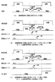
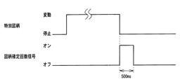
可変表示の第1実行条件が成立(例えば、第1始動入賞口11;ただし、第1始動入賞口11、第2始動入賞口12、第3始動入賞口13のうちの任意の2つの始動入賞口であってもよい。)したことにもとづいて各々を識別可能な第1識別情報(例えば第1特別図柄)の可変表示を開始し表示結果を導出表示する第1可変表示手段(例えば、図104に示す第1特別図柄表示器8a)と、可変表示の第2実行条件が成立(例えば、第3始動入賞口13への入賞;ただし、第1始動入賞口11、第2始動入賞口12、第3始動入賞口13のうちの任意の2つの始動入賞口であってもよい。)したことにもとづいて各々を識別可能な第2識別情報(例えば第3識別情報)の可変表示を開始し表示結果を導出表示する第2可変表示手段(例えば、図104に示す第2特別図柄表示器8b)とを備えた遊技機であって、遊技の進行を制御する遊技制御処理(例えば図20のステップS21〜S35の処理)の実行中に発生する制御情報(例えば、図52に示す始動口1信号、始動口2信号、始動口3信号、図柄確定回数信号、大当り1信号、大当り2信号、V信号、役物開放回数信号)を遊技機の外部に設けられている外部装置(例えば、ホールコンピュータ)に出力する遊技制御情報出力手段(例えば、遊技制御用マイクロコンピュータ560におけるステップS30の処理を実行する部分)を備え、遊技制御情報出力手段は、第1実行条件が成立したときに該第1実行条件が成立したことを示す第1実行条件成立情報(例えば、始動口1信号;ただし、始動口2信号や始動口3信号であってもよい。)を外部装置に出力し、第2実行条件が成立したときに該第2実行条件が成立したことを示す第2実行条件成立情報(例えば、始動口3信号;ただし、始動口1信号や始動口2信号であってもよい。)を外部装置に出力する実行条件成立情報出力手段(例えば、遊技制御用マイクロコンピュータ560におけるステップS1002の処理を実行する部分)を含み、実行条件成立情報出力手段は、所定の期間(例えば500ms)内に第1実行条件と第2実行条件とが成立したときは、一方の実行条件の成立にもとづく実行条件成立情報を出力してから予め設定した期間が経過した後に他方の実行条件の成立にもとづく実行条件成立情報を出力する(例えば、ステップS1116〜S1130の処理を実行する。具体的には、図53に示すように、始動口1信号が出力されているときに当該始動口1信号の出力終了時から500ms経過後に始動口1信号を出力し、第1始動口スイッチ以外の入賞情報信号が出力されているときは当該入賞情報信号の出力終了時から500ms経過後に始動口1信号を出力する。また、図54に示すように、始動口2信号が出力されているときに当該始動口2信号の出力終了時から500ms経過後に始動口2信号を出力し、第2始動口スイッチ以外の入賞情報信号が出力されているときは当該入賞情報信号の出力終了時から500ms経過後に始動口2信号を出力する。また、図55に示すように、、始動口3信号が出力されているときに当該始動口3信号の出力終了時から500ms経過後に始動口3信号を出力し、第3始動口スイッチ以外の入賞情報信号が出力されているときは当該入賞情報信号の出力終了時から500ms経過後に始動口3信号を出力する)ように構成されていてもよい。
The first execution condition of variable display is satisfied (for example, the first
可変表示の第1実行条件が成立(例えば、第1始動入賞口1013への入賞)したことにもとづいて各々を識別可能な第1識別情報(例えば第1特別図柄)の可変表示を開始し表示結果を導出表示する第1可変表示手段(例えば、第1特別図柄表示器1008a)と、可変表示の第2実行条件が成立(例えば、第2始動入賞口1014への入賞)したことにもとづいて各々を識別可能な第2識別情報(例えば第2特別図柄)の可変表示を開始し表示結果を導出表示する第2可変表示手段(例えば、第2特別図柄表示器1008b)とを備えた遊技機(例えば、図90に示す遊技機)であって、第1実行条件または第2実行条件が成立したことにもとづいて、いずれの実行条件が成立したのかを示す成立識別コマンド(例えば、第1始動入賞指定コマンド、第2始動入賞指定コマンド)を送信するとともに、第1実行条件または第2実行条件が成立したことを特定可能な特定コマンド(例えば、合算保留記憶数指定コマンド)を送信する特定コマンド送信手段(例えば、遊技制御用マイクロコンピュータ560におけるステップS2118,S2119を実行する部分)と、該特定コマンド送信手段が送信した成立識別コマンドと特定コマンドとにもとづいて、第1実行条件および第2実行条件の成立数(例えば合算保留記憶数)を認識可能に表示する成立数表示手段(例えば、演出制御用マイクロコンピュータ100において図99〜図100に示す保留記憶表示制御処理を実行する部分)とを備え、成立数表示手段は、特定コマンド送信手段から成立識別コマンドを受信せずに特定コマンドを受信したときには、所定の表示態様で第1実行条件または第2実行条件が成立したことを表示することにより、第1実行条件および第2実行条件の成立数を認識可能に表示する(例えば、演出制御用マイクロコンピュータ100がステップS1931の処理を実行する)ように構成されていてもよい。
The variable display of the first identification information (for example, the first special symbol) that can be identified based on the fact that the first execution condition of the variable display is satisfied (for example, winning to the first start winning opening 1013) is started and displayed. Based on the first variable display means for deriving and displaying the result (for example, the first special symbol display device 1008a) and the second execution condition for variable display being satisfied (for example, winning in the second start winning opening 1014). A gaming machine comprising second variable display means (for example, a second special
請求項1記載の発明では、第1可変入賞球装置または第2可変入賞球装置が開放動作を実行するときに、当該開放動作を実行する第1可変入賞球装置または第2可変入賞球装置への異常入賞を報知するために用いられる閾値を記憶する閾値記憶手段と、第1可変入賞球装置に入賞した遊技球を検出して第1検出信号を出力する第1検出手段と、第2可変入賞球装置に入賞した遊技球を検出して第2検出信号を出力する第2検出手段と、第1可変入賞球装置の開放動作の実行中に第1検出手段から第1検出信号が出力されたことにもとづいて第1可変入賞球装置への入賞数を計測する第1入賞数計測手段と、第2可変入賞球装置の開放動作の実行中に第2検出手段から第2検出信号が出力されたことにもとづいて第2可変入賞球装置への入賞数を計測する第2入賞数計測手段と、第1可変入賞球装置および第2可変入賞球装置のいずれも開放動作を実行していない通常遊技状態において第1検出手段または第2検出手段から第1検出信号または第2検出信号が出力されたことにもとづいて異常入賞と判定する通常異常入賞判定手段と、第1可変入賞球装置の開放動作の実行中に第1入賞数計測手段により計測された入賞数が第1可変入賞球装置への異常入賞を報知するために用いられる第1閾値を超えたこと、または第2可変入賞球装置の開放動作の実行中に第2入賞数計測手段により計測された入賞数が第2可変入賞球装置への異常入賞を報知するために用いられる閾値を超えたことにもとづいて異常入賞と判定する特定異常入賞判定手段と、通常異常入賞判定手段または特定異常入賞判定手段により異常入賞と判定された場合に異常報知を実行する異常報知実行手段とを備え、閾値記憶手段が、第1可変入賞球装置の開放動作における第1可変入賞球装置への入賞の標準値よりも多い値である第1閾値を記憶し、第2可変入賞球装置の開放動作における第2可変入賞球装置への入賞の標準値よりも多い値であって第1閾値とは異なる値の第2閾値を記憶するように構成されている。このような構成によれば、通常遊技状態および特定遊技状態等のいずれの遊技状態においても異常入賞を的確に検出し判定することができる。また、第1可変入賞球装置の開放動作中のときと第2可変入賞球装置の開放動作中のときとで異常入賞の判定における入賞数を異なる値にして判定することができ、いずれの可変入賞球装置の開放動作中においても異常入賞を的確に検出し判定することができる。 According to the first aspect of the present invention, when the first variable winning ball device or the second variable winning ball device performs the opening operation, the first variable winning ball device or the second variable winning ball device that executes the opening operation. Threshold storage means for storing a threshold value used for notifying the abnormal winning of the game, first detection means for detecting a game ball won in the first variable winning ball apparatus and outputting a first detection signal, and a second variable Second detection means for detecting a game ball won in the winning ball apparatus and outputting a second detection signal, and the first detection signal is output from the first detection means during the opening operation of the first variable winning ball apparatus. And a second detection signal is output from the second detection means during the execution of the opening operation of the second variable winning ball apparatus. The number of winnings to the second variable winning ball device based on what has been made The first detection means or the second detection means performs the first detection in the normal game state in which neither the first winning prize number measuring means to measure, nor the first variable winning ball apparatus and the second variable winning ball apparatus perform the opening operation. A normal abnormal winning determination means for determining an abnormal winning based on the output of the signal or the second detection signal, and a winning measured by the first winning number measuring means during the opening operation of the first variable winning ball apparatus. When the number exceeds the first threshold used to notify the abnormal winning to the first variable winning ball device, or is measured by the second winning number measuring means during the opening operation of the second variable winning ball device. Specific abnormal winning determination means for determining abnormal winning based on the fact that the number of winnings exceeds a threshold value used for notifying abnormal winning to the second variable winning ball device, and normal abnormal winning determination means or specific abnormal And an abnormality notification executing means for executing an abnormality notification when the prize determination means determines that the prize is abnormal, and the threshold value storage means is for winning the first variable winning ball device in the opening operation of the first variable winning ball device. A first threshold value that is greater than the standard value is stored, and is a value that is greater than the standard value for winning the second variable winning ball device in the opening operation of the second variable winning ball device, and is different from the first threshold value. The second threshold value is configured to be stored. According to such a configuration, an abnormal winning can be accurately detected and determined in any gaming state such as a normal gaming state and a specific gaming state. In addition, the number of winnings in the abnormal winning determination can be determined differently depending on whether the first variable winning ball apparatus is in the opening operation or the second variable winning ball apparatus is in the opening operation. Even during the opening operation of the winning ball apparatus, the abnormal winning can be accurately detected and determined.
請求項2記載の発明では、異常入賞判定手段によって異常入賞が発生したと判定されたことまたは異常状態判定手段によって所定の異常状態が発生したと判定されたことにもとづいて、遊技機の外部に設けられている外部装置に所定の異常信号を出力するための外部出力手段を備えるように構成されているので、異常入賞が発生したことおよび遊技機において所定の異常状態が発生したことなど複数の異常が発生したことを示す情報を外部装置に出力することができる。また、外部出力手段が、異常入賞判定手段によって異常入賞が発生したと判定されたときと異常状態判定手段によって所定の異常状態が発生したと判定されたときとで、遊技機に設けられた共通の出力端子から所定の異常信号を出力可能とするように構成されているので、外部装置に情報を出力するための機構の部品数の増加や配線作業の複雑化を防ぐことができる。
In the invention according to
請求項3記載の発明では、第2可変入賞球装置制御手段が、複数種類の開放パターンのうち、成立した第2移行条件の種類に応じた開放パターンにもとづいて、第2可変入賞球装置を閉鎖状態と開放状態とに変化させ、閾値記憶手段が、開放パターンに応じて異なる第2閾値を記憶するように構成されているので、第2可変入賞球装置の開放回数や開放時間の異なる複数種類の第2可変入賞球装置の開放動作が実行可能な遊技機であっても、第2可変入賞球装置の開放動作の種類に応じた最適な閾値にもとづき異常入賞の判定を行うことができる。従って、いずれの第2可変入賞球装置の開放動作においても異常入賞判定を的確に実行することができ、異常入賞をより確実に防止することができる。
In the invention according to
請求項4記載の発明では、始動動作制御手段が、第1可変表示手段に第1識別情報の表示結果として第1開放表示結果が導出表示されたときに、可変入賞球装置が所定回数開放状態となる第1始動動作状態に移行する第1始動動作制御手段と、第2可変表示手段に第2識別情報の表示結果として第2開放表示結果が導出表示されたときに、第1始動動作状態よりも遊技者にとって有利な第2始動動作状態に移行する第2始動動作制御手段とを含む構成であるので、遊技のバリエーションを増加させることができ、遊技興趣を向上させることができる。
In the invention according to
請求項5記載の発明では、閾値記憶手段が、通常遊技状態における第1可変入賞球装置または第2可変入賞球装置への異常入賞を報知するために用いられる閾値を記憶し、入賞数計測手段が、通常遊技状態においても第1検出手段または第2検出手段から第1検出信号または第2検出信号が出力されたことにもとづいて第1可変入賞球装置または第2可変入賞球装置への入賞数を計測し、通常異常入賞判定手段が、通常遊技状態において入賞数計測手段により計測された入賞数が通常遊技状態における第1可変入賞球装置または第2可変入賞球装置への異常入賞を報知するために用いられる閾値を超えたことにもとづいて異常入賞と判定し、閾値記憶手段が、特定遊技状態における閾値と通常遊技状態における閾値を記憶手段の共通の領域に記憶するように構成されているので、異常入賞判定処理を簡易化することができるとともに、記憶手段の領域の削減を実現することができる。
In the invention according to
請求項6記載の発明では、異常報知実行手段は、通常異常入賞判定手段により異常入賞と判定された場合と特定異常入賞判定手段により異常入賞と判定された場合とで共通の態様の異常報知を実行するように構成されているので、報知態様を閾値の種類分備える必要がなくなり、データ容量の削減を実現することができる。
In the invention described in
請求項7記載の発明では、異常報知実行手段は、通常異常入賞判定手段により異常入賞と判定された場合と特定異常入賞判定手段により異常入賞と判定された場合とで異なる態様の異常報知を実行するように構成されているので、発生した異常の種類を遊技店員等に知らせることができる。 In the seventh aspect of the invention, the abnormality notification execution means executes abnormality notification in a different mode between the case where the abnormal winning determination is determined by the normal abnormality winning determination means and the case where the abnormal winning determination is determined by the specific abnormality winning determination means. Therefore, it is possible to inform the game store clerk of the type of abnormality that has occurred.
請求項8記載の発明では、通常遊技状態における閾値が少なくとも2以上であるので、可変入賞球装置(第1可変入賞球装置または第2可変入賞球装置)内で遊技球が詰まり、特定遊技状態が終了した後に詰まりが解消したことによって遊技球の入賞が検出されたような場合であっても、異常入賞と判定されなくなる。従って、不正な入賞でないにもかかわらず異常入賞であると判定されてしまうのを極力防止することができる。
In the invention described in
請求項9記載の発明では、遊技制御情報出力手段が、第1実行条件が成立したときに第1実行条件が成立したことを示す第1実行条件成立情報を外部装置に出力し、第2実行条件が成立したときに第2実行条件が成立したことを示す第2実行条件成立情報を外部装置に出力する実行条件成立情報出力手段を含み、実行条件成立情報出力手段は、所定の期間内において第1実行条件と第2実行条件とが成立したときは、一方の実行条件の成立にもとづく実行条件成立情報を出力してから所定の期間が経過した後に他方の実行条件の成立にもとづく実行条件成立情報を出力するように構成されているので、第1実行条件の成立と第2実行条件の成立が予め設定した期間内に連続して発生した場合であっても、各々の実行条件の成立にもとづく実行条件成立情報を外部装置において認識させることができる。 According to the ninth aspect of the present invention, the game control information output means outputs the first execution condition establishment information indicating that the first execution condition is established when the first execution condition is established to the external device, and the second execution Including execution condition establishment information output means for outputting second execution condition establishment information indicating that the second execution condition is established to the external device when the condition is established, the execution condition establishment information output means within a predetermined period When the first execution condition and the second execution condition are satisfied, the execution condition based on the satisfaction of the other execution condition after a predetermined period of time has elapsed after the execution condition satisfaction information is output based on the satisfaction of the one execution condition Since the establishment information is output, even if the establishment of the first execution condition and the establishment of the second execution condition occur continuously within a preset period, the establishment of each execution condition Execution based on The matter establishment information can be recognized in the external device.
請求項10記載の発明では、成立数表示手段が、特定コマンド送信手段から成立識別コマンドを受信せずに特定コマンドを受信したときには、所定の表示態様で第1実行条件または第2実行条件が成立したことを表示することにより、第1実行条件および第2実行条件の成立数を認識可能に表示するように構成されているので、成立識別コマンドを取りこぼした場合においても成立数を遊技者に認識可能に表示することができ、遊技者に不信感を与えるのを防止することができる。
In the invention according to
実施の形態1.
以下、本発明の一実施形態を図面を参照して説明する。
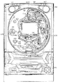
まず、遊技機の一例であるパチンコ遊技機の全体の構成について説明する。図1は、パチンコ遊技機を正面からみた正面図である。
Hereinafter, an embodiment of the present invention will be described with reference to the drawings.
First, the overall configuration of a pachinko gaming machine that is an example of a gaming machine will be described. FIG. 1 is a front view of a pachinko gaming machine as viewed from the front.
図1に示すように、パチンコ遊技機1は、額縁状に形成されたガラス扉枠2を有する。ガラス扉枠2の下部表面には打球供給皿(上皿)3がある。打球供給皿3の下部には、打球供給皿3に収容しきれない遊技球を貯留する余剰球受皿4と、打球発射装置が遊技球を発射する速さ(すなわち、遊技球を弾くばねの強さ)を調整する打球操作ハンドル(操作ノブ)5とが設けられている。
As shown in FIG. 1, the
遊技者は、操作ノブ5を回転させることにより、打球発射装置から発射される遊技球の勢いを調整することができる。具体的には、操作ノブ5を右に回転させていくことにより、打球発射装置から発射される遊技球の速さが徐々に増していき、所定の速さを越えると、発射された遊技球は打球レールを通って上方より遊技領域7の左側領域に入る。さらに操作ノブ5を右に回転させていくと、発射された遊技球は上方より遊技領域7の右側領域に入る。よって、操作ノブ5を右に回転させた状態で回転量を変化させることで、打球発射装置から発射される遊技球の勢いを調整することができ、遊技球を打ち込む領域を調整することができる。
The player can adjust the momentum of the game ball fired from the ball striking device by rotating the
ガラス扉枠2の背面には、遊技盤6が着脱可能に取り付けられている。なお、遊技盤6は、それを構成する板状体と、その板状体に取り付けられた種々の部品とを含む構造体である。また、遊技盤6の前面には誘導レールで区画された遊技領域7が形成されている。
A
遊技領域7のほぼ中央には、可変入賞球装置20が配置されている。可変入賞球装置20の下方には、第1始動入賞口11と、第2始動入賞口12と、第3始動入賞口13を形成する可変入賞球装置15とが設けられている。第1始動入賞口11に入った入賞球は第1始動口スイッチ11aによって検出され、第2始動入賞口12に入った入賞球は第2始動口スイッチ12aによって検出され、それぞれ、遊技盤6の背面に導かれる。また、可変入賞球装置15が開状態になることによって入賞可能になる第3始動入賞口13に入った入賞球は第3始動口スイッチ13aによって検出され、遊技盤6の背面に導かれる。可変入賞球装置15は、ソレノイド15aによって開状態にされる。以下、第1始動入賞口11と、第2始動入賞口12と、第3始動入賞口13とを、「始動入賞口」と総称したり、始動入賞口11,12,13と表すことがある。また、第1始動口スイッチ11aと、第2始動口スイッチ12aと、第3始動口スイッチ13aとを、「始動口スイッチ」と総称したり、始動口スイッチ11a,12a,13aと表すことがある。
A variable winning
遊技球が始動入賞口に入賞し始動口スイッチによって検出され小当りとなった場合には、可変入賞球装置20が1回または2回開閉制御される。開閉制御によって、左側の開放扉76Aが初期位置から左方向に移動し、右側の開放扉76Bが初期位置から右方向に移動することによって、可変入賞球装置20は開放状態になり、開放扉76A,76Bが初期位置に戻ることによって可変入賞球装置20は閉鎖状態になる。このように始動口スイッチの入賞検出に応じて可変入賞球装置20が開放動作を行う状態を始動動作状態という。以下、可変入賞球装置20を、大入賞口(第2大入賞口、上大入賞口)または役物ということがある。また、遊技盤6には種々の役物が設けられているが、以下、役物という場合には、可変入賞球装置20を意味する。
When the game ball wins the start winning opening and is detected by the start opening switch and is a small hit, the variable winning
また、可変入賞球装置20は、大当り遊技の開始条件(例えば、始動動作状態において遊技球が特定領域に入賞したこと。)が成立すると、所定回数すなわち所定ラウンド数、開閉制御される。その状態を大当り遊技状態(特定遊技状態)という。大当り遊技状態では、高い割合で入賞が生じ、多数の遊技球が遊技者に払い出される。なお、始動動作状態を除き、可変入賞球装置20が開閉制御される状態(大当り遊技状態)を第2大当り遊技状態ということがある。
Further, the variable winning
可変入賞球装置20の内部における背面側には、演出表示を行うLCDなどによる演出表示装置9が設けられている。演出表示装置9は、識別情報としての飾り図柄を可変表示(変動表示)する。この実施の形態では、演出表示装置9には、例えば「左」、「中」、「右」の3つの可変表示部(図柄表示エリア)がある(図73の「飾り図柄表示領域9a」参照)。
An
可変入賞球装置20の右方には、識別情報としての特別図柄を可変表示する特別図柄表示器8が設けられている。特別図柄表示器8は、例えば、7セグメント表示器によって構成される。
On the right side of the variable winning
特別図柄表示器8の上方には、始動入賞口に遊技球が入った有効入賞球数すなわち始動記憶数(保留記憶数)を表示する4つのLEDからなる特別図柄保留記憶表示器18が設けられている。特別図柄保留記憶表示器18は、始動記憶数を入賞順に4個まで表示する。特別図柄保留記憶表示器18は、始動入賞口11,12,13に有効始動入賞がある毎に、点灯状態のLEDの数を1増やす。そして、特別図柄表示器8で可変表示が開始される毎に、点灯状態のLEDの数を1減らす(すなわち1つのLEDを消灯する)。この例では、特別図柄保留記憶表示器18は、特別図柄表示器8で可変表示が開始される毎に、点灯状態をシフトする。なお、後述するように、演出表示装置9でも始動記憶数が表示されるので(図73の「保留記憶数表示領域9c」参照)、特別図柄保留記憶表示器18を設けなくてもよい。
Above the
可変入賞球装置20の左方には、普通図柄を可変表示する普通図柄表示器10が設けられている。遊技領域7に設けられているゲート32を遊技球が通過しゲートスイッチ32aで検出されると、普通図柄表示器10において普通図柄(この例では、7セグメントLEDでの数字表示)の可変表示が開始される。この実施の形態では、当りの場合には可変表示の終了時に「7」が停止表示され、はずれの場合には「7」以外が停止表示される。当りの場合には、可変入賞球装置15が所定回数、所定時間だけ開状態になる。普通図柄表示器10の上方には、ゲート32を通過した通過球数を表示する4つのLEDによる表示部を有する普通図柄保留記憶表示器41が設けられている。ゲート32の通過がある毎に、普通図柄保留記憶表示器41は点灯するLEDを1増やす。そして、普通図柄表示器10の可変表示が開始される毎に、点灯するLEDを1減らす。なお、ゲート32を2つ設け、いずれのゲート32を遊技球が通過しても、1つの普通図柄表示器10において普通図柄の変動が開始されるようにしてもよい。
On the left side of the variable winning
可変入賞球装置15の下部には、特定遊技状態(大当り遊技状態)においてソレノイド21によって開閉板16が開状態にされる大入賞口(第1大入賞口、下大入賞口)が設けられている。開閉板16は、大入賞口を開閉する手段である。大入賞口に入った入賞球はカウントスイッチ23で検出される。なお、この実施の形態では、所定個数(例えば10個)の遊技球が大入賞口に入賞した場合または所定時間(例えば29秒)経過した場合に、大当り遊技状態における次のラウンドが開始される(最終ラウンドの場合を除く。)。以下、可変入賞球装置20による大入賞口を第2大入賞口(または上大入賞口)といい、開閉板16による大入賞口を第1大入賞口(下大入賞口)ということがある。第1大入賞口と第2大入賞口とを「大入賞口」と総称することがある。
Under the variable winning
また、開閉板16の右方には入賞口(普通入賞口)38が設けられ、開閉板16の左方には入賞口(普通入賞口)39が設けられている。遊技球の入賞口38,39に入賞した遊技球は、入賞口スイッチ38a,39aによって検出される。入賞口38,39は、遊技媒体を受け入れて入賞を許容する領域として遊技盤6に設けられる入賞領域を構成している。なお、始動入賞口も、遊技媒体を受け入れて入賞を許容する入賞領域を構成し、大入賞口(第1大入賞口および第2大入賞口)の内部にも入賞領域が設けられている。入賞領域に遊技球が入賞すると、所定個の遊技球が景品(賞球)として遊技者に払い出される。
In addition, a winning opening (ordinary winning opening) 38 is provided on the right side of the opening /
遊技領域7の左右周辺には、遊技中に点滅表示される装飾ランプが設けられ、下部には、入賞しなかった遊技球を回収するアウト口26がある。
Decorative lamps blinking and displayed during the game are provided around the left and right sides of the
また、遊技領域7の外側の左右上部には、効果音を発する2つのスピーカ27が設けられている。遊技領域7の外周には、天枠ランプ28a、左枠ランプ28bおよび右枠ランプ28cが設けられている。さらに、遊技領域7における各構造物(可変入賞球装置20等)の周囲には装飾LEDが設置されている。天枠ランプ28a、左枠ランプ28bおよび右枠ランプ28cおよび装飾用LEDは、遊技機に設けられている装飾発光体の一例である。
Two
そして、この例では、左枠ランプ28bの近傍に、賞球払出中に点灯する賞球LED51が設けられ、右枠ランプ28cの近傍に、補給球が切れたときに点灯する球切れLED52が設けられている。さらに、プリペイドカードが挿入されることによって球貸しを可能にするプリペイドカードユニットが、パチンコ遊技機1に隣接して設置される(図示せず)。
In this example, a prize ball LED 51 that is lit during award ball payout is provided in the vicinity of the
打球発射装置から発射された遊技球は、打球レールを通って遊技領域7に入り、その後、遊技領域7を落下する。打球が始動入賞口(第1始動入賞口11、第2始動入賞口12または第3始動入賞口13)に入り始動口スイッチ(第1始動口スイッチ11a、第2始動口スイッチ12aまたは第3始動口スイッチ13a)で検出されると、図柄の可変表示を開始できる状態であれば、特別図柄表示器8において特別図柄が可変表示を始めるとともに、演出表示装置9において飾り図柄が可変表示を始める。図柄の可変表示を開始できる状態でなければ、特別図柄表示器8での特別図柄の可変表示の保留記憶である始動入賞記憶数が上限数でない場合には、始動入賞記憶数を1増やす。すなわち、特別図柄保留記憶表示器18における点灯するLEDを1増やす。
The game ball launched from the ball striking device enters the
特別図柄表示器8における特別図柄(「0」〜「9」)の可変表示は、所定時間が経過したときに停止する。停止時の特別図柄が大当り図柄(特定表示結果:具体的には、例えば「7」)であると、大当り遊技状態のうちの第1大当り遊技状態(始動動作状態を経ずに開始される大当り遊技状態)に移行する。また、停止時の特別図柄が小当り図柄(開放表示結果:具体的には、例えば「0」「1」「2」「4」「5」「6」「8」「9」)である場合には、始動動作状態に移行する。なお、始動動作状態のことを小当り遊技状態ともいう。始動動作状態において、可変入賞球装置20の内部に設けられている特別領域に遊技球が入賞すると、第2大当り遊技状態(始動動作状態を経た後に開始される大当り遊技状態)に移行する。
The variable display of special symbols (“0” to “9”) on the
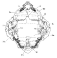
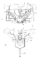
次に、可変入賞球装置20について、図2〜図10を参照して説明する。図2および図3は、遊技盤6に設けられている可変入賞球装置20を正面からみた正面図である。図4は、図2および図3に示されている開放扉76A,76Bの裏面側に設けられている遊技球の通過口71,72,73を有する構造物を示す斜視図である。図5は、通過口71から特定領域を形成する特定入賞口66に至る経路を示す斜視図である。図6は、通過口73から特定領域を形成する特定入賞口66に至る経路を示す斜視図である。図7(A)、図8(A)および図9は、可変入賞球装置20の下部を上側から見た上面図であり、図7(B)および図8(B)は、可変入賞球装置20の下部を正面側から見た正面図である。図9には、特定入賞口66の直上に設けられている回転体(円盤)86も示されている。図10は、回転体86を上側から見た上面図である。なお、図3、図5〜図9において、矢印は遊技球の進路を示す。
Next, the variable winning
可変入賞球装置(役物)20は、開閉モータ75の駆動によって開放扉76A,76Bが開放状態になると、遊技球が進入可能な状態になる。役物20に進入した遊技球は、通過口71,72,73のいずれかを通過して、役物20における下部側に流下する。通過口71を通過した遊技球は、第1役物入賞スイッチ71aで検出され、通過口72を通過した遊技球は、第2役物入賞スイッチ72aで検出され、通過口73を通過した遊技球は、第3役物入賞スイッチ73aで検出される。通過口72を通過した遊技球は、誘導樋73Aを通過して役物20内の右方に導かれる。また、通過口71,73を通過した遊技球は、誘導樋71Aを通過して役物20内の左方に導かれる。なお、図2には、開放扉76A,76Bが閉鎖して遊技球が役物20に進入不能である状態が示され、図3には、開放扉76A,76Bが開放した状態が示されている。また、第1役物入賞スイッチ71aと、第2役物入賞スイッチ72aと、第3役物入賞スイッチ73aとを、「役物入賞スイッチ」と総称することがある。
When the
開放扉76A,76B(図4において図示せず)は、図4に示す構造物の手前側に設けられている。遊技球は、図4に示す構造物における3つの通路(手前側から奥側に向かう経路)のいずれかを通って通過口71,72,73のいずれかに至る。開放扉76A,76Bが閉鎖している状態(完全閉鎖状態)では、遊技球は、3つの通過口71,72,73のいずれにも進入不能である。開放扉76A,76Bが開放状態になると、3つの通過口71,72,73のいずれかに進入できる状態になるが、開放扉76A,76Bが最も開いている状態(完全開放状態)では3つの通過口71,72,73のいずれにも進入可能であるが、通過口71,73に遊技球が進入する確率は、通過口72に進入する確率よりも高い。また、開放扉76A,76Bが完全開放状態から完全閉鎖状態に移行する期間では、開放面積が狭くなるにつれて、左右の通過口71,73に比べて、中央の通過口72を通過しやすくなる。また、完全閉鎖状態から完全開放状態に移行する期間では、中央の通過口72に遊技球が進入しやすい状態から、3つの通過口71,72,73のいずれにも進入可能な状態に徐々に移行する。
つまり、開放扉76A,76Bが完全閉鎖状態から開放状態への移行を開始した直後、および完全閉鎖状態に戻る直前では、相対的に、遊技球が中央の通過口72を通過する割合が高くなる。なお、開放扉76A,76Bが開放するということは役物20が開放状態になるということであり、開放扉76A,76Bが閉鎖するということは役物20が閉鎖状態になるということである。また、開放扉76Aと開放扉76Bとは、対称状態で移動する。対称状態で移動するとは、中心(中央の通過口72の中心軸)から開放扉76Aの端部(中央の通過口72寄りの端部)までの距離と、中心から開放扉76Bの端部(中央の通過口72寄りの端部)までの距離とが常に同じであることを意味する。
That is, immediately after the opening
役物20の左右両側には、可動部材77,78が設けられている。可動部材77において動く部分は可動部77Aであり、可動部材78において動く部分は可動部78Aである。可動部77Aは可動部駆動ソレノイド77Bによって動かされ、可動部78Aは可動部駆動ソレノイド78Bによって動かされる。可動部77Aおよび可動部78Aは、それぞれ、上下方向に動く。役物20における最下部に設けられている特定領域を形成する特定入賞口66に入賞した遊技球は、特定領域スイッチ66aで検出される。なお、遊技球が特定入賞口66に入賞し特定領域スイッチ66aで検出されたことをV入賞ともいう。
通過口71,73を通過し誘導樋71A(図5において図示せず)によって導かれた遊技球は、図5(A)に示すように、特定入賞口66に至る通路71Bを通って、特定領域に到達することが可能である。通路71Bは、中途から、上方が開放している開放部(樋状通路)になり、開放部の始まり部分に、通路71Bに繋がり特定領域に到達不能な通路であるはずれ通路71Cが設けられている。図5(B)に示すように、可動部77Aは、動作時(下位置にあるとき)に通路71Bの開放部の始まり部分において通路71Bの下流への遊技球の通過を阻止し、遊技球をはずれ通路71Cに導く。図5(A)に示すように、可動部77Aが上位置にあるときには、遊技球は、可動部77Aに阻止されず、可動部77Aが設けられている位置から通路71Bの下流側に流下する。
As shown in FIG. 5 (A), a game ball that has passed through the
通過口72を通過し誘導樋73A(図6において図示せず)によって導かれた遊技球は、図6(A)に示すように、特定入賞口66に至る通路73Bを通って、特定領域に到達することが可能である。通路73Bは、中途から、上方が開放している開放部(樋状通路)になっている。通路73Bの開放部は湾曲し、開放部の始まり部分における湾曲の内側には壁が存在しない。図6(B)に示すように、可動部78Aは、動作時(下位置にあるとき)に通路73Bの開放部の始まり部分において通路73Bの下流への遊技球の通過を阻止し、遊技球を、内壁が存在しない部分から、特定領域に到達不能な通路であるはずれ通路73Cに導く。図6(A)に示すように、可動部78Aが上位置にあるときには、遊技球は、可動部78Aに阻止されず、遠心力によって湾曲の外側の壁に沿うように通路73Bを流れるので、可動部78Aが設けられている位置から通路73Bの下流側に流下する。
As shown in FIG. 6 (A), the game ball that has passed through the
通路73Bは、途中穴74に至る。途中穴74の直下に回転体86が設けられている。回転体86は、火山をモチーフにした円錐状に形成された役物で、頂部に平坦部を有している。途中穴74を通過した遊技球は、回転体86の側に流下する。
The
図7(A)に示すように、途中穴74を通過した遊技球は、通路74Bを通って特定領域の側に流下する。通路74Bは、回転体86の上部において、通過口71,73からの経路である通路71Bと合流する。
As shown in FIG. 7A, the game ball that has passed through the
図7(B)に示すように、特定入賞口66に入賞し特定領域スイッチ66aで検出された遊技球は、さらに役物排出スイッチ85aで検出される。なお、特定入賞口66に入賞しなかった遊技球も、役物排出スイッチ85aで検出される。つまり、この実施の形態では、役物20に進入した全ての遊技球は、役物排出スイッチ85aで検出される。なお、特定入賞口66に入賞した遊技球は役物排出スイッチ85aで検出されず、特定入賞口66に入賞しなかった遊技球のみが役物排出スイッチ85aで検出されるように、球経路を構成してもよい。その場合には、特定領域スイッチ66aで検出された遊技球の数と役物排出スイッチ85aで検出された遊技球の数との和が、役物20から排出された遊技球の数になる。
As shown in FIG. 7B, the game ball that has won the specific winning
図8(A)に示すように、はずれ通路71C,73Cを通った遊技球は、特定入賞口66の直上の近傍に形成されているはずれ口67,68から、特定入賞口66を通らない経路に誘導される。
As shown in FIG. 8 (A), the game balls that have passed through the slipping
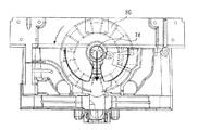
回転体86は、円盤状に形成され、回転軸を上下方向に向けて配置されている。また、図10に示すように、回転体86の外周縁部には複数の孔部86Cが形成され、その外周縁部の一部には、切り欠き部86Aが設けられている。また、回転体86におけるドーナツ部の内側の領域(内部領域)は、平面状に形成された領域である。図10に示す例では、7個の孔部86Cが設けられている。途中穴74から通路74Bに入った遊技球および通路71B,73Bを通過した遊技球は回転体86の外周縁部に至る。このとき、回転体86の切り欠き部86Aが、正面に位置している場合、すなわち特定入賞口66の上部にある合流部81(図8参照)に位置している場合には、特定入賞口66に入賞可能である。また、孔部86Cが位置している場合には、孔部86Cに入った遊技球は、回転体86によって移動され、はずれ口69から、特定入賞口66を通らない経路に誘導される。なお、孔部86Cは底面を有していない連通穴である。よって、孔部86Cに入った遊技球は下部に落下可能であるが、遊技球が入った孔部86Cがはずれ口69の位置に来るまでの間、回転体86の裏面の構造物によって落下は阻止されている。また、孔部86Cの内壁部によって、孔部86Cから特定入賞口66に向かって落下することも阻止されている。なお、1つの孔部86Cとそれに隣接する孔部86Cとの間(以下、平面部86Cという。)は平面状になっているので、そこから遊技球が下部に落下することはない。
The rotating
図9に破線矢印で示すように、回転体86は、回転体駆動モータ87(図10参照)の駆動によって回転(この例では、反時計回りに回転)する。回転体86の回転中に、切り欠き部86Aが特定入賞口66の直上に位置したときに回転体86に到達した遊技球は、切り欠き部86Aから回転体86の外周側に抜け落ち、特定入賞口66に入賞可能である。
As indicated by broken line arrows in FIG. 9, the rotating
また、図10に示すように、回転体86の近傍には、位置検出のための複数(この例では2つ)センサ87a,87bが設けられている。各センサ87a,87bは、例えば、回転体86を挟むように設置されている発光ダイオード等の発光素子とフォトダイオードやフォトトランジスタ等の受光素子とからなり、回転体86には穴部87cが設けられている。穴部87cは、回転体86の内部領域における所定位置に形成されている。具体的には、回転体86が回転して、穴部を含む領域がセンサ設置位置に対応する位置にくると発光素子からの光を受光素子側に通過させるような位置に形成されている。なお、各センサにおける受光素子を、以下、第1位置センサ87aおよび第2位置センサ87bという。
As shown in FIG. 10, a plurality of (two in this example)
途中穴74を通過し通路74Bを通って回転体86に到達した遊技球は、切り欠き部86Aが特定入賞口66の直上に位置しているときには、ほぼ必ず切り欠き部86Aから落下して特定入賞口66に入賞する。また、通路74Bは、円錐状の役物の傾斜面上に形成されている。従って、特定入賞口66の真上に平面部86Cが位置している場合でも、通路74Bを通過する遊技球には勢いがついているので、その遊技球は平面部86Cを乗り越えて特定入賞口66に落下するようになっている。
The game ball that has passed through the
よって、この実施の形態では、遊技球が中央の通過口72を通過した場合には、遊技球が左の通過口71または右の通過口73を通過した場合に比べて、高い確率でV入賞が生ずる。つまり、通過口72からの右ルートは、通過口71,73からの左ルートに対して、遊技球を特定入賞口66に誘導しやすくなっている。
Therefore, in this embodiment, when the game ball passes through the
なお、この実施の形態では、小当り遊技状態および第2大当り遊技状態において、遊技球が役物入賞スイッチで検出された場合に入賞が生じたとする。すなわち、3つの役物入賞スイッチ71a,72a,73aが設けられている領域が入賞領域に相当する。しかし、可変入賞球装置20の内部において役物入賞スイッチとは別に遊技球を検出するスイッチを設け、遊技球がそのスイッチで検出された場合に入賞が生じたとしてもよい。
In this embodiment, it is assumed that a winning occurs when a game ball is detected by the accessory winning switch in the small hit game state and the second big hit game state. That is, an area in which the three
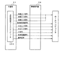
次に、役物(可変入賞球装置20)内の背面側に設けられている各基板について説明する。図11は、可変入賞球装置20に取り付けられた各基板の配置を示す説明図である。図11に示すように、役物20には、裏面上方、下方、左方および右方にそれぞれ基板950A〜950Dが取り付けられている。以下、役物20の左方に取り付けられた基板950Aをセンター左基板といい、右方に取り付けられた基板950Bをセンター右基板といい、上方に取り付けられた基板950Dをセンター上基板といい、下方に取り付けられた基板950Cをセンター下基板ともいう。センター左基板950Aには、装飾表示灯としての複数のランプ196aが搭載されている。また、センター左基板950Aには、磁気を検出するための磁気センサ95aが搭載されている。また、センター右基板950Bには、装飾表示灯としての複数のランプ196bが搭載されている。また、センター右基板950Bには、磁気を検出するための磁気センサ95fが搭載されている。また、センター下基板950Cには、装飾表示灯としての複数のランプ196cが搭載されている。また、センター下基板950Cには、磁気を検出するための3つの磁気センサ95b,95c,95eが搭載されている。以下、磁気センサ95aを第1磁気センサといい、磁気センサ95bを第2磁気センサといい、磁気センサ95cを第3磁気センサといい、磁気センサ95dを第4磁気センサといい、磁気センサ95eを第5磁気センサといい、磁気センサ95fを第6磁気センサともいう。また、センター上基板905Dには、装飾表示灯としての複数のランプ196dが搭載されている。
Next, each board | substrate provided in the back side in the accessory (variable winning ball apparatus 20) is demonstrated. FIG. 11 is an explanatory diagram showing the arrangement of the substrates attached to the variable winning
この実施の形態では、磁気センサ95a〜95fとしてリードスイッチを用いる。リードスイッチは、2本の強磁性体リードが所定の接点間隔をおいて相対するように配置され、ガラス管の中に封入された形状に形成されている。そして、このリードスイッチにリードの軸方向に磁界を外部から加えると、リードが磁化され、相対した自由端が互いに吸引しあい接触して回路を導通状態にすることができる。
In this embodiment, reed switches are used as the
磁気センサ95a〜95fは、役物20に入った遊技球を磁石などを用いて特定入賞口66に入賞させようとするような不正行為が行われると、異常磁気の存在を検出し検出信号を出力する。この実施の形態では、図11に示すように、各磁気センサ95a〜95fは、長手方向がガラス扉枠2の正面ガラスの面に交差する方向に配置され、正面ガラス側から磁石を用いて行われる不正行為を検知しやすくなっている。リードスイッチは、その構造上、長手方向に強く磁気を検出するように指向性をもち、長手方向に交差する方向には指向性を強くもたない。そのため、磁石を用いた不正行為が行われやすい部位にリードスイッチの長手方向に交差する方向が位置するように配置していしまうと、磁石を用いた不正行為をうまく検知できない場合がある。そのため、この実施の形態では、リードスイッチである各磁気センサ95a〜95fを、磁石を用いた不正行為が行われやすい部位に対して、長手方向に位置するように配置する。
The
また、図11に示すように、遊技盤6の役物20が取り付けられている部分の右下方の裏側には、振動センサ96aが搭載された振動センサ基板96が取り付けられている。この実施の形態では、遊技機をゆするなどの不正行為が行われると、振動センサ96aが振動を検出し検出信号を出力する。なお、振動センサ96aを、主基板31または演出制御基板80などの他の基板に設けるようにしてもよい。
Also, as shown in FIG. 11, a
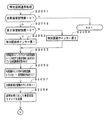
図12は、この実施の形態の遊技機の遊技の進み方の一例を示す説明図である。図12に示すように、始動入賞口に遊技球が入賞していずれかの始動口スイッチ11a,12a,13aの検出信号がオン状態になると、すなわち始動入賞が生ずると、遊技の進行を制御する遊技制御手段によって抽選が実行される。抽選の結果は、「大当り」「小当り」または「はずれ」となる。そして、特別図柄および飾り図柄の変動(可変表示)が開始される。特別図柄および飾り図柄の変動が終了すると、大当りに決定されている場合(大当り図柄が導出表示された場合)には、遊技状態が大当り遊技状態(第1大当り遊技状態)に移行される。第1大当り遊技状態では、開閉板16による大入賞口(第1大入賞口)が16回(16ラウンド、1ラウンドの開放許容時間は29秒)開閉制御される。なお、この実施の形態では、大当り遊技状態におけるラウンド数は16で一定あるが、ラウンド数(例えば、2ラウンド、7ラウンド、16ラウンドのいずれか)を抽選等によって決定するようにしてもよい。
FIG. 12 is an explanatory diagram showing an example of how the game progresses in the gaming machine of this embodiment. As shown in FIG. 12, when the game ball is won at the start winning opening and the detection signal of any of the start opening switches 11a, 12a, 13a is turned on, that is, when a start winning occurs, the progress of the game is controlled. A lottery is executed by the game control means. The result of the lottery is “big hit”, “small hit” or “out of game”. Then, the variation (variable display) of the special symbol and the decorative symbol is started. When the variation of the special symbol and the decorative symbol is finished, when the big hit is determined (when the big hit symbol is derived and displayed), the gaming state is shifted to the big hit gaming state (first big hit gaming state). In the first big hit gaming state, the opening / closing control of the big winning opening (first big winning opening) by the opening /
小当りに決定されている場合(小当り図柄が導出表示された場合)には、遊技制御手段は、役物20を開放状態に制御して始動動作を開始させる。始動動作状態において、役物20は、0.9秒間開放状態になる。開放状態になる回数(開放回数)は、1回または2回である。始動動作状態において、遊技球が役物20に入賞し、さらに、遊技球が特定入賞口66に入賞して特定領域スイッチ66aで検出されるとV入賞が発生する。V入賞が発生すると、遊技状態が大当り遊技状態(第2大当り遊技状態)に移行される。第2大当り遊技状態では、役物20(可変入賞球装置、第2大入賞口)が3回、7回または11回(3ラウンド、7ラウンドまたは11ラウンド:1ラウンドの開放許容時間は29秒)開閉制御される。V入賞が発生しなかった場合には、第2大当り遊技状態に移行しない。なお、この実施の形態では、小当り図柄の種類に応じて、第2大当り遊技状態におけるラウンド数が決定される(図22参照)。
When the small hit is determined (when the small hit symbol is derived and displayed), the game control means controls the accessory 20 to the open state and starts the starting operation. In the starting operation state, the
なお、この実施の形態では、小当り遊技(始動動作状態における遊技)が終了すると、第2大当り遊技状態に移行する前に、演出表示装置9等を用いた所定の演出(始動動作状態後の演出)が実行される。なお、小当り遊技においてV入賞が発生しなかった場合にも始動動作状態後の演出は実行される。
In this embodiment, when the small hit game (game in the starting operation state) is completed, before the transition to the second big hit game state, the predetermined display (after the starting operation state) using the
図13は、特別図柄の変動と小当り遊技の開始とを説明するための説明図である。図13に示すように、「始動入賞」が生ずると、特別図柄表示器8において特別図柄の変動が行われ、それに同期して演出表示装置9において表示演出が行われる。変動時間が経過すると、特別図柄の停止図柄が導出表示され、停止図柄が大当り図柄でない場合には、役物20が開放(羽根開放)し小当り遊技が開始される。なお、以下に説明するように、特別図柄の変動に同期して演出表示装置9において飾り図柄の変動が行われるが(図73参照)、図13では、飾り図柄の変動は記載省略されている。また、演出表示装置9において保留記憶数の表示が行われるが(図73参照)、図13では、保留記憶数の表示は記載省略されている。さらに、時短状態(特別図柄の変動時間が短縮される時間短縮状態)のときは、演出表示装置9において残り時短回数の表示が行われるが(図73参照)、図13では、残り時短回数の表示が記載省略されている。
FIG. 13 is an explanatory diagram for explaining the change of the special symbol and the start of the small hit game. As shown in FIG. 13, when the “start winning prize” occurs, the
図14は、特別図柄および飾り図柄の変動と小当り遊技の開始および大当り遊技の開始とを説明するための説明図である。図14に示すように、「始動入賞」が生ずると、特別図柄表示器8において特別図柄の変動が行われ、それに同期して演出表示装置9において表示演出が行われる。なお、図14に示す例は、後述する変動パターン#7A〜#7Cが用いられる場合の例である。変動時間が経過すると、特別図柄の停止図柄が導出表示され、停止図柄が小当り図柄(「0」「1」「2」「4」「5」「6」「8」「9」)である場合には、役物20が開放(羽根開放)し小当り遊技が開始される。停止図柄が大当り図柄(「7」)である場合には、大当り表示(「大当り」)が行われ、大当たり遊技が開始される。その場合、小当り遊技(始動動作状態の遊技)は、実行されない。停止図柄がはずれ図柄(「3」)である場合には、小当り遊技および大当り遊技のいずれも開始されず、次の図柄の変動に移行される。
FIG. 14 is an explanatory diagram for explaining the variation of the special symbol and the decorative symbol, the start of the small hit game, and the start of the big hit game. As shown in FIG. 14, when the “start winning prize” occurs, the
このように、この実施の形態では、特別図柄の停止図柄が特定の図柄になったときに発生する大当たり遊技状態(第1大当たり遊技状態)と、小当り遊技においてV入賞が生ずると発生する大当たり遊技状態(第2大当たり遊技状態)とがあるので、遊技者は、複数種類の大当たり遊技を享受することができる。なお、変動パターン#7A〜#7Cが用いられる場合には、変動時間が長いので、結果として小当りになる場合でも、遊技者に、変動時間が終了するまで、始動動作状態を経ない大当たりの発生を期待させることができる。このことは、変動パターン#8A〜#8C,#9A〜#9Cが用いられる場合も同様である。また、以下に説明するように、特別図柄の変動に同期して演出表示装置9において飾り図柄の変動が行われるが、図14では、飾り図柄の変動は記載省略されている。
Thus, in this embodiment, the jackpot game state (first jackpot game state) that occurs when the stop symbol of the special symbol becomes a specific symbol, and the jackpot that occurs when a V-winning occurs in the jackpot game Since there is a game state (second jackpot game state), the player can enjoy a plurality of types of jackpot games. Note that when the
図15は、小当り遊技終了後の演出の期間を説明するための説明図である。図15(A)には、始動動作状態で役物20が開放状態になったときに遊技球が役物20に全く入賞しなかった場合の例が示されている。その場合には、遅延時間すなわち入賞監視時間(この例では2秒)が経過したら、一定時間(この例では3秒)の演出(例えば、図83(A)に例示する演出)が実行される。
FIG. 15 is an explanatory diagram for explaining the period of the effect after the end of the small hit game. FIG. 15 (A) shows an example in which the game ball does not win the
図15(B)には、始動動作状態で役物20が開放状態になったときに遊技球が役物20に入賞したがV入賞しなかった場合の例が示されている。その場合には、入賞監視時間(この例では2秒)が経過したこと、および役物20に入賞した全ての遊技球が役物20から排出されたことが確認されたことの双方の条件が成立したら、一定時間の演出(例えば、図83(B)に例示する演出)が実行される。そして、演出時間が終了したら、保留記憶数が0でない場合には、保留記憶にもとづいて特別図柄の変動が開始される。なお、図15(B)には、役物20に1個の遊技球が入賞した場合の例、および入賞監視時間が経過したときにまだ役物20から排出されていない遊技球があった場合の例が示されている。
FIG. 15 (B) shows an example in which the game ball wins the
図15(C)には、始動動作状態で役物20が開放状態になったときに遊技球が役物20に入賞し、かつ、V入賞した場合の例が示されている。その場合には、入賞監視時間(この例では2秒)が経過したこと、および役物20に入賞した全ての遊技球が役物20から排出されたことが確認されたことの双方の条件が成立したら、一定時間の演出(例えば、図83(C),(D)に例示する演出)が実行される。そして、演出時間が終了したら、大入賞口が開放する大当り遊技状態に移行する。なお、図15(C)には、役物20に1個の遊技球が入賞した場合の例、および入賞監視時間が経過する前に全ての遊技球が役物20から排出された場合の例が示されている。
FIG. 15C shows an example in which the game ball wins the winning
図15に示すように、この実施の形態では、始動動作が終了すると、必ず(始動動作状態に対応して毎回、すなわち表示結果が小当り図柄となる可変表示に対応して毎回)、演出が実行される。なお、この実施の形態では、演出時間は一定であるが、例えば、V入賞が生じたときとV入賞が生じなかったときとで演出時間を変えるようにしてもよい。 As shown in FIG. 15, in this embodiment, every time the start operation is completed (every time corresponding to the start operation state, that is, every time corresponding to the variable display in which the display result is a small hit symbol), the production is always performed. Executed. In this embodiment, the production time is constant, but the production time may be changed depending on, for example, when a V prize is generated and when a V prize is not generated.
なお、入賞監視時間とは、遊技球が役物20に入った時点から、その遊技球が役物入賞スイッチ71a,72a,73aのいずれかで検出されるまでの時間に余裕を持たせた時間である。具体的には、遊技球が役物20に入った時点から、役物入賞スイッチ71a,72a,73aのうち最も検出が遅れるスイッチが確実に遊技球を検出できるまでの時間である。入賞監視時間を設けることによって、役物20に入った遊技球が検出される前に演出が開始されることが防止される。
Note that the winning monitoring time is the time from when the game ball enters the accessory 20 until the game ball is detected by any of the
図16は、特別図柄の停止図柄と当りの種類との関係を示す説明図である。図16に示すように、特別図柄の停止図柄にははずれ図柄(この例では、「3」)と大当り図柄(この例では、「7」)と小当り図柄(この例では、「3」および「7」以外)とがあるが、小当り図柄と第2大当り遊技状態におけるラウンド数とは対応している。また、小当り図柄と始動動作状態における役物20の開放回数は対応している。よって、小当り遊技においてV入賞が生ずる前の段階で遊技者の有利不利(開放回数)に関わる表示がなされ、特定入賞口66に遊技球が入賞するか否かに遊技者の興味を引きつけることができる。なお、この実施の形態では、ラウンド数は小当り図柄の種類で決まるが、小当り図柄の種類に加えて、通過口71,72,73のいずれを遊技球が通過したかによって、決定されるラウンド数の範囲や種類、ラウンドの振り分け割合を異ならせるようにしてもよい。また、特定入賞口66を遊技球が通過したこと(V入賞が発生したこと)にもとづいて乱数を抽出し、抽出した乱数値にもとづいてラウンド数を決定するようにしてもよい。
FIG. 16 is an explanatory diagram showing a relationship between a special symbol stop symbol and a winning type. As shown in FIG. 16, the special symbol stop symbol is an off symbol (“3” in this example), a big hit symbol (“7” in this example), and a small hit symbol (in this example, “3”). However, the small hit symbol and the number of rounds in the second big hit gaming state correspond to each other. Further, the small hit symbol corresponds to the number of times the
なお、役物20は、始動動作状態および大当り遊技状態においてのみ開放状態に制御される。従って、それらの状態以外の遊技状態では、遊技球は役物に入賞しない。よって、それらの状態以外の遊技状態(平常状態)で役物の内部において入賞が検出されたということは、その入賞は正規の入賞でない(異常入賞である)ことになる。そこで、この実施の形態では、異常入賞が生じた場合には、その旨の報知を行う。よって、役物20を備えた遊技機において、不正行為を発見しやすくなっている。
Note that the
図17は、主基板(遊技制御基板)31における回路構成の一例を示すブロック図である。なお、図14には、払出制御基板37および演出制御基板80等も示されている。主基板31には、プログラムに従ってパチンコ遊技機1を制御する遊技制御用マイクロコンピュータ(遊技制御手段に相当)560が搭載されている。遊技制御用マイクロコンピュータ560は、ゲーム制御(遊技進行制御)用のプログラム等を記憶するROM54、ワークメモリとして使用される記憶手段としてのRAM55、プログラムに従って制御動作を行うCPU56およびI/Oポート部57を含む。この実施の形態では、ROM54およびRAM55は遊技制御用マイクロコンピュータ560に内蔵されている。すなわち、遊技制御用マイクロコンピュータ560は、1チップマイクロコンピュータである。1チップマイクロコンピュータには、少なくともCPU56のほかRAM55が内蔵されていればよく、ROM54は外付けであっても内蔵されていてもよい。また、I/Oポート部57は、外付けであってもよい。
FIG. 17 is a block diagram showing an example of the circuit configuration of the main board (game control board) 31. As shown in FIG. FIG. 14 also shows a
遊技制御用マイクロコンピュータ560には、さらに、ハードウェア乱数を発生する乱数回路503が内蔵されている。乱数回路503は、遊技制御用マイクロコンピュータ560に内蔵されるのではなく、主基板31において、遊技制御用マイクロコンピュータ560の外部に設けられていてもよい。
The
RAM55は、その一部または全部が電源基板において作成されるバックアップ電源によってバックアップされている不揮発性記憶手段としてのバックアップRAMである。この実施の形態では、RAM55の全部が、電源バックアップされている。
The
なお、遊技制御用マイクロコンピュータ560においてCPU56がROM54に格納されているプログラムに従って制御を実行するので、以下、遊技制御用マイクロコンピュータ560(またはCPU56)が実行する(または、処理を行う)ということは、具体的には、CPU56がプログラムに従って制御を実行することである。このことは、主基板31以外の他の基板に搭載されているマイクロコンピュータについても同様である。
In the
また、ゲートスイッチ32a、第1始動口スイッチ11a、第2始動口スイッチ12a、第3始動口スイッチ13a、第1役物入賞スイッチ71a、第2役物入賞スイッチ72a、第3役物入賞スイッチ73a、特定領域スイッチ66a、役物排出スイッチ85a、入賞口スイッチ38a,39a、カウントスイッチ23、第1位置センサ87aおよび第2位置センサ87bからの検出信号を遊技制御用マイクロコンピュータ560に与える入力ドライバ回路58も主基板31に搭載されている。また、可変入賞球装置15を開閉するためのソレノイド15a、開閉板16を開閉するためのソレノイド21、開閉扉76A,76Bを開閉させる開閉モータ75、可動部77Aを動作させる可動部駆動ソレノイド77B、可動部78Aを動作させる可動部駆動ソレノイド78Bを遊技制御用マイクロコンピュータ560からの指令に従って駆動する出力回路59も主基板31に搭載されている。さらに、大当り遊技状態の発生を示す大当り情報等の情報出力信号をホールコンピュータ等の外部装置に対して出力する情報出力回路(図示せず)も主基板31に搭載されている。
In addition, the
また、遊技制御用マイクロコンピュータ560は、I/Oポート部57を介して磁気センサ95a〜95fおよび振動センサ96aからの検出信号を入力する。
Further, the
また、遊技制御用マイクロコンピュータ560は、特別図柄を可変表示する特別図柄表示器8、普通図柄を可変表示する普通図柄表示器10、特別図柄保留記憶表示器18および普通図柄保留記憶表示器41の表示制御を行う。
In addition, the
この実施の形態では、演出制御基板80に搭載されている演出制御手段(演出制御用マイクロコンピュータで構成される。)が、中継基板177を介して遊技制御用マイクロコンピュータ560からの演出制御コマンドを受信し、演出表示装置9の表示制御、ランプの点灯制御およびスピーカ27の制御を行う。
In this embodiment, an effect control means (configured by an effect control microcomputer) mounted on the
図18は、中継基板177、演出制御基板80、ランプドライバ基板35および音声出力基板70の回路構成例を示すブロック図である。なお、図18に示す例では、ランプドライバ基板35および音声出力基板70には、マイクロコンピュータは搭載されていないが、マイクロコンピュータを搭載してもよい。また、ランプドライバ基板35および音声出力基板70を設けずに、演出制御に関して演出制御基板80のみを設けてもよい。
FIG. 18 is a block diagram illustrating a circuit configuration example of the
演出制御基板80は、演出制御用CPU101およびRAMを含む演出制御用マイクロコンピュータ100を搭載している。なお、RAMは外付けであってもよい。演出制御基板80において、演出制御用CPU101は、内蔵または外付けのROM(図示せず)に格納されたプログラムに従って動作し、中継基板177を介して入力される主基板31からの取込信号(演出制御INT信号)に応じて、入力ドライバ102および入力ポート103を介して演出制御コマンドを受信する。また、演出制御用CPU101は、演出制御コマンドにもとづいて、VDP(ビデオディスプレイプロセッサ)109に、演出表示装置9の表示制御を行わせる。
The
演出制御コマンドおよび演出制御INT信号は、演出制御基板80において、まず、入力ドライバ102に入力する。入力ドライバ102は、中継基板177から入力された信号を演出制御基板80の内部に向かう方向にしか通過させない(演出制御基板80の内部から中継基板177への方向には信号を通過させない)信号方向規制手段としての単方向性回路でもある。
The effect control command and the effect control INT signal are first input to the
さらに、中継基板177には、主基板31から入力された信号を演出制御基板80に向かう方向にしか通過させない(演出制御基板80から中継基板77への方向には信号を通過させない)信号方向規制手段としての単方向性回路177Aが搭載されている。単方向性回路として、例えばダイオードやトランジスタが使用される。図18には、ダイオードが例示されている。また、単方向性回路は、各信号毎に設けられる。さらに、単方向性回路である出力ポート571を介して主基板31から演出制御コマンドおよび演出制御INT信号が出力されるので、中継基板177から主基板31の内部に向かう信号が規制される。すなわち、中継基板177からの信号は主基板31の内部(遊技制御用マイクロコンピュータ560側)に入り込まない。なお、出力ポート571は、図17に示されたI/Oポート部57の一部である。また、出力ポート571の外側(中継基板77側)に、さらに、単方向性回路である信号ドライバ回路が設けられていてもよい。
Further, the signal input from the
また、演出制御用CPU101は、入力ポート106を介して磁気センサ95a〜95fおよび振動センサ96aからの検出信号を入力する。このように、磁気センサ95a〜95fおよび振動センサ96aからの検出信号が演出制御用CPU101に入力されるように構成されているので、CPU56に対して不正な信号が入力される余地を低減することができる。すなわち、磁気センサ95a〜95fおよび振動センサ96aからの検出信号がCPU56に入力されるように構成された場合には、その信号線(信号入力経路)を利用してCPU56に対して不正な信号(例えば、擬似的に入賞が発生したと認識させるような信号や強制的に大当りを発生させるような信号など)が入力される可能性がある。しかし、図18に示すように、磁気センサ95a〜95fおよび振動センサ96aからの検出信号が演出制御用CPU101に入力される場合には、そのような不正な信号が演出制御用CPU101に入力されても出球等に影響を及ぼすことはなく、不正行為に利用されるおそれはない。
The effect control CPU 101 also receives detection signals from the
さらに、演出制御用CPU101は、出力ポート105を介してランプドライバ基板35に対してランプを駆動する信号を出力する。また、演出制御用CPU101は、出力ポート104を介して音声出力基板70に対して音番号データを出力する。
Further, the effect control CPU 101 outputs a signal for driving the lamp to the
ランプドライバ基板35において、ランプを駆動する信号は、入力ドライバ351を介してランプドライバ352に入力される。ランプドライバ352は、ランプを駆動する信号を増幅して天枠ランプ28a、左枠ランプ28b、右枠ランプ28cなどの枠側に設けられている各ランプに供給する。また、枠側に設けられている装飾ランプ(図示せず)に供給する。
In the
音声出力基板70において、音番号データは、入力ドライバ702を介して音声合成用IC703に入力される。音声合成用IC703は、音番号データに応じた音声や効果音を発生し増幅回路705に出力する。増幅回路705は、音声合成用IC703の出力レベルを、ボリューム706で設定されている音量に応じたレベルに増幅した音声信号をスピーカ27に出力する。音声データROM704には、音番号データに応じた制御データが格納されている。音番号データに応じた制御データは、所定期間(例えば飾り図柄の変動期間)における効果音または音声の出力態様を時系列的に示すデータの集まりである。
In the
なお、ランプを駆動する信号および音番号データは、演出制御用CPU101とランプドライバ基板35および音声出力基板70との間で、双方向通信(信号受信側から送信側に応答信号を送信するような通信)によって伝達される。
The signal for driving the lamp and the sound number data are communicated between the effect control CPU 101, the
演出制御用CPU101は、受信した演出制御コマンドに従ってキャラクタROM(図示せず)から必要なデータを読み出す。キャラクタROMは、演出表示装置9に表示されるキャラクタ画像データ、具体的には、人物、文字、図形または記号等(飾り図柄、背景図柄を含む)をあらかじめ格納しておくためのものである。演出制御用CPU101は、キャラクタROMから読み出したデータをVDP109に出力する。VDP109は、演出制御用CPU101から入力されたデータにもとづいて表示制御を実行する。
The effect control CPU 101 reads necessary data from a character ROM (not shown) in accordance with the received effect control command. The character ROM is for storing character image data displayed on the
この実施の形態では、演出制御用マイクロコンピュータ100と共動して演出表示装置9の表示制御を行うVDP109が演出制御基板80に搭載されている。VDP109は、演出制御用マイクロコンピュータ100とは独立したアドレス空間を有し、そこにVRAMをマッピングする。VRAMは、VDPによって生成された画像データを展開するためのバッファメモリである。そして、VDP109は、VRAM内の画像データを演出表示装置9に出力する。
In this embodiment, a
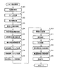
次に、遊技機の動作について説明する。図19は、主基板31における遊技制御用マイクロコンピュータ560が実行するメイン処理を示すフローチャートである。遊技機に対して電源が投入され電力供給が開始されると、リセット信号が入力されるリセット端子の入力レベルがハイレベルになり、遊技制御用マイクロコンピュータ560(具体的には、CPU56)は、プログラムの内容が正当か否か確認するための処理であるセキュリティチェック処理を実行した後、ステップS1以降のメイン処理を開始する。メイン処理において、CPU56は、まず、必要な初期設定を行う。
Next, the operation of the gaming machine will be described. FIG. 19 is a flowchart showing main processing executed by the
初期設定処理において、CPU56は、まず、割込禁止に設定する(ステップS1)。次に、割込モードを割込モード2に設定し(ステップS2)、スタックポインタにスタックポインタ指定アドレスを設定する(ステップS3)。そして、内蔵デバイスの初期化(内蔵デバイス(内蔵周辺回路)であるCTC(カウンタ/タイマ)およびPIO(パラレル入出力ポート)の初期化など)を行った後(ステップS4)、RAMをアクセス可能状態に設定する(ステップS5)。なお、割込モード2は、CPU56が内蔵する特定レジスタ(Iレジスタ)の値(1バイト)と内蔵デバイスが出力する割込ベクタ(1バイト:最下位ビット0)とから合成されるアドレスが、割込番地を示すモードである。また、CPU56は、乱数回路503を初期設定する処理も実行する。CPU56は、乱数回路503にランダムRの値を更新させるための設定を行う。乱数回路503は、所定のクロック信号を用いて乱数を発生させる。一例として、乱数回路503は、CPU56から数値が読み出されるときに、0〜598の数値のいずれかの数値をCPU56に出力するように設定される。
In the initial setting process, the
次いで、CPU56は、入力ポートを介して入力されるクリアスイッチ(例えば、電源基板に搭載されている。)の出力信号の状態を確認する(ステップS6)。その確認においてオンを検出した場合には、CPU56は、通常の初期化処理を実行する(ステップS10〜S15。S44,S45を含む。)。
Next, the
クリアスイッチがオンの状態でない場合には、遊技機への電力供給が停止したときにバックアップRAM領域のデータ保護処理(例えばパリティデータの付加等の電力供給停止時処理)が行われたか否か確認する(ステップS7)。そのような保護処理が行われていないことを確認したら、CPU56は初期化処理を実行する。バックアップRAM領域にバックアップデータがあるか否かは、例えば、電力供給停止時処理においてバックアップRAM領域に設定されるバックアップフラグの状態によって確認される。
If the clear switch is not on, check whether data protection processing of the backup RAM area (for example, power supply stop processing such as addition of parity data) was performed when power supply to the gaming machine was stopped (Step S7). When it is confirmed that such protection processing is not performed, the
電力供給停止時処理が行われたことを確認したら、CPU56は、バックアップRAM領域のデータチェックを行う(ステップS8)。この実施の形態では、データチェックとしてパリティチェックを行う。よって、ステップS8では、算出したチェックサムと、電力供給停止時処理で同一の処理によって算出され保存されているチェックサムとを比較する。不測の停電等の電力供給停止が生じた後に復旧した場合には、バックアップRAM領域のデータは保存されているはずであるから、チェック結果(比較結果)は正常(一致)になる。チェック結果が正常でないということは、バックアップRAM領域のデータが、電力供給停止時のデータとは異なっていることを意味する。そのような場合には、内部状態を電力供給停止時の状態に戻すことができないので、電力供給の停止からの復旧時でない電源投入時に実行される初期化処理を実行する。
After confirming that the power supply stop process has been performed, the
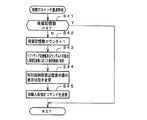
チェック結果が正常であれば、CPU56は、遊技制御手段の内部状態と演出制御手段等の電気部品制御手段の制御状態を電力供給停止時の状態に戻すための遊技状態復旧処理(ステップS41〜S43の処理)を行う。具体的には、ROM54に格納されているバックアップ時設定テーブルの先頭アドレスをポインタに設定し(ステップS41)、バックアップ時設定テーブルの内容を順次作業領域(RAM55内の領域)に設定する(ステップS42)。作業領域はバックアップ電源によって電源バックアップされている。バックアップ時設定テーブルには、作業領域のうち初期化してもよい領域についての初期化データが設定されている。ステップS41およびS42の処理によって、作業領域のうち初期化してはならない部分については、保存されていた内容がそのまま残る。初期化してはならない部分とは、例えば、電力供給停止前の遊技状態を示すデータ(特別図柄プロセスフラグなど)、出力ポートの出力状態が保存されている領域(出力ポートバッファ)、未払出賞球数を示すデータが設定されている部分などである。
If the check result is normal, the
また、CPU56は、電力供給復旧時の初期化コマンドとしての停電復旧指定コマンドを送信する(ステップS43)。そして、ステップS15に移行する。
Further, the
なお、この実施の形態では、バックアップフラグとチェックデータとの双方を用いてバックアップRAM領域のデータが保存されているか否か確認しているが、いずれか一方のみを用いてもよい。すなわち、バックアップフラグとチェックデータとのいずれかを、遊技状態復旧処理を実行するための契機としてもよい。 In this embodiment, it is confirmed whether the data in the backup RAM area is stored using both the backup flag and the check data. However, only one of them may be used. That is, either the backup flag or the check data may be used as an opportunity for executing the game state restoration process.
初期化処理では、CPU56は、まず、RAMクリア処理を行う(ステップS10)。なお、RAMクリア処理によって、所定のデータ(例えば大当り判定用乱数を生成するためのカウンタのカウント値のデータ)は0に初期化されるが、任意の値またはあらかじめ決められている値に初期化するようにしてもよい。また、RAM55の全領域を初期化せず、所定のデータ(例えば大当り判定用乱数を生成するためのカウンタのカウント値のデータ)をそのままにしてもよい。また、ROM54に格納されている初期化時設定テーブルの先頭アドレスをポインタに設定し(ステップS11)、初期化時設定テーブルの内容を順次作業領域に設定する(ステップS12)。
In the initialization process, the
ステップS10〜S12の処理によって、例えば、特別図柄プロセスフラグなど制御状態に応じて選択的に処理を行うためのフラグに初期値(例えば0)が設定される。 By the processing in steps S10 to S12, for example, an initial value (for example, 0) is set to a flag for performing processing selectively according to the control state, such as a special symbol process flag.
また、CPU56は、サブ基板(主基板31以外のマイクロコンピュータが搭載された基板。)を初期化するための初期化指定コマンド(遊技制御用マイクロコンピュータ560が初期化処理を実行したことを示すコマンドでもある。)をサブ基板に送信する(ステップS13)。例えば、演出制御用マイクロコンピュータ100は、初期化指定コマンドを受信すると、演出表示装置9において、遊技機の制御の初期化がなされたことを報知するための画面表示、すなわち初期化報知を行う。
Further, the
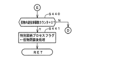
さらに、CPU56は、異常報知禁止フラグをセットするとともに(ステップS44)、禁止期間タイマに禁止期間値に相当する値を設定する(ステップS45)。禁止期間値は、後述する異常入賞の報知を禁止する期間を示す値である。また、異常報知禁止フラグは、異常入賞の報知が禁止されていることを示すフラグであり、禁止期間タイマがタイムアウトするまでセット状態に維持される。よって、演出表示装置9において初期化報知が開始されてから所定期間は、異常入賞の報知の開始が禁止される。
Further, the
また、CPU56は、異常入賞数をカウントする異常入賞判定カウンタに閾値として「3」の値を設定する(ステップS46)。ステップS46で設定される閾値は、大当り遊技状態(第1大当り遊技状態、第2大当り遊技状態)・小当り遊技状態(始動動作状態)以外の平常状態における大入賞口(第1大入賞口16、第2大入賞口20)への遊技球の入賞を許容する値である。すなわち、平常状態においては、本来、大入賞口(第1大入賞口16、第2大入賞口20)に遊技球が入賞するはずがないが、大入賞口(第1大入賞口16、第2大入賞口20)内に遊技球が詰まり、大当り遊技状態・小当り遊技状態が終了した後に詰まりが解消したことによって遊技球の入賞が検出されるような場合も考えられる。また、ノイズ等によってカウントスイッチ23や役物入賞スイッチ71a〜73aから検出信号が出力されたと誤検出されるような場合も考えられる。そこで、この実施の形態では、平常状態においてカウントスイッチ23等が遊技球を検出したとしても、検出数が2回まで(つまり大入賞口への入賞数が2個まで)は、大入賞口への遊技球の入賞を許容すべく、ステップS46において閾値として「3」の値が設定されている。後述するように、カウントスイッチ23等の検出数が3回になると、異常入賞が発生したと判定して異常報知を実行するための処理を実行する(図67のステップS588、S589参照)。なお、異常入賞判定カウンタは、RAM55の所定領域に形成されている。
Further, the
そして、ステップS15において、CPU56は、所定時間(例えば2ms)毎に定期的にタイマ割込がかかるように遊技制御用マイクロコンピュータ560に内蔵されているCTCのレジスタの設定を行なう。すなわち、初期値として例えば2msに相当する値が所定のレジスタ(時間定数レジスタ)に設定される。この実施の形態では、2ms毎に定期的にタイマ割込がかかるとする。
In step S15, the
初期化処理の実行(ステップS10〜S15)が完了すると、CPU56は、メイン処理で、表示用乱数更新処理(ステップS17)および初期値用乱数更新処理(ステップS18)を繰り返し実行する。表示用乱数更新処理および初期値用乱数更新処理を実行するときには割込禁止状態に設定し(ステップS16)、表示用乱数更新処理および初期値用乱数更新処理の実行が終了すると割込許可状態に設定する(ステップS19)。この実施の形態では、表示用乱数とは、普通図柄の停止図柄を決定するための乱数等であり、表示用乱数更新処理とは、表示用乱数を発生するためのカウンタのカウント値を更新する処理である。また、初期値用乱数更新処理とは、初期値用乱数を発生するためのカウンタのカウント値を更新する処理である。この実施の形態では、初期値用乱数とは、普通図柄の表示結果を当り図柄とするか否か決定するための乱数を発生するためのカウンタ(普通図柄当り判定用乱数発生カウンタ)である。後述する遊技の進行を制御する遊技制御処理(遊技制御用マイクロコンピュータ560が、遊技機に設けられている演出表示装置、可変入賞球装置、球払出装置等の遊技用の装置を、自身で制御する処理、または他のマイクロコンピュータに制御させるために指令信号を送信する処理、遊技装置制御処理ともいう。)において、普通図柄当り判定用乱数を発生するためのカウンタのカウント値が1周(普通図柄当り判定用乱数の取りうる値の最小値から最大値までの間の数値の個数分歩進したこと)すると、そのカウンタに初期値が設定される。
When the execution of the initialization process (steps S10 to S15) is completed, the
なお、図19には示していないが、電源投入時(例えば、ステップS5の処理の実行後、ステップS45の処理の実行後など)に、回転体86を初期位置に戻す制御が実行される。
Although not shown in FIG. 19, when the power is turned on (for example, after execution of the process of step S5, after execution of the process of step S45, etc.), control for returning the rotating
タイマ割込が発生すると、CPU56は、図20に示すステップS20〜S35のタイマ割込処理を実行する。タイマ割込処理において、まず、電源断信号が出力されたか否か(オン状態になったか否か)を検出する電源断検出処理を実行する(ステップS20)。電源断信号は、例えば電源基板に搭載されている電圧低下監視回路が、遊技機に供給される電源の電圧の低下を検出した場合に出力する。そして、電源断検出処理において、CPU56は、電源断信号が出力されたことを検出したら、必要なデータをバックアップRAM領域に保存するための電力供給停止時処理を実行する。次いで、入力ドライバ回路58を介して、ゲートスイッチ32a、第1始動口スイッチ11a、第2始動口スイッチ12a、第3始動口スイッチ13a、第1役物入賞スイッチ71a、第2役物入賞スイッチ72a、第3役物入賞スイッチ73a、特定領域スイッチ66a、役物排出スイッチ85a、入賞口スイッチ38a,39a、カウントスイッチ23、第1位置センサ87aおよび第2位置センサ87bの検出信号を入力し、それらの状態判定を行う(スイッチ処理:ステップS21)。
When the timer interrupt occurs, the
次に、CPU56は、特別図柄表示器8、普通図柄表示器10、特別図柄保留記憶表示器18および普通図柄保留記憶表示器41の表示制御を行う表示制御処理を実行する(ステップS22)。特別図柄表示器8および普通図柄表示器10については、ステップS33,S34で設定された出力バッファの内容に応じて各表示器に対して駆動信号を出力する制御を実行する。
Next, the
また、CPU56は、正規の時期以外の時期において大入賞口に遊技球が入賞したことを検出した場合等に異常入賞の報知を行わせるための処理を行う(ステップS23:異常入賞報知処理)。
In addition, the
次に、遊技制御に用いられる大当り判定用の乱数等の各判定用乱数を生成するための各カウンタのカウント値を更新する処理を行う(判定用乱数更新処理:ステップS24)。CPU56は、さらに、初期値用乱数および表示用乱数を生成するためのカウンタのカウント値を更新する処理を行う(初期値用乱数更新処理,表示用乱数更新処理:ステップS25,S26)。
Next, a process of updating the count value of each counter for generating each determination random number such as a big hit determination random number used for game control is performed (determination random number update process: step S24). The
図21は、各乱数を示す説明図である。各乱数は、以下のように使用される。
(1)ランダム2:特別図柄の変動パターン(変動時間)を決定する(変動パターン決定用)
(2)ランダム3:普通図柄にもとづく当りを発生させるか否か決定する(普通図柄当り判定用)
(3)ランダム4:ランダム3の初期値を決定する(ランダム3初期値決定用)
(4)ランダム5:普通図柄の停止図柄を決定する(普通図柄決定用)
FIG. 21 is an explanatory diagram showing each random number. Each random number is used as follows.
(1) Random 2: Determine the variation pattern (variation time) of a special symbol (for variation pattern determination)
(2) Random 3: Determines whether or not to generate a hit based on a normal symbol (for normal symbol hit determination)
(3) Random 4: Determine initial value of random 3 (for determining random 3 initial value)
(4) Random 5: Determine the stop symbol of the normal symbol (for normal symbol determination)
なお、大当りにするのか小当りにするのかを決定するための大当り判定用乱数として、乱数回路503が生成する乱数が用いられる。以下、大当り判定用乱数を、ランダム1またはランダムRということがある。また、(1)〜(4)の乱数(ランダム2〜ランダム5)をソフトウェア乱数ということがある。
Note that a random number generated by the
図20に示された遊技制御処理におけるステップS24では、遊技制御用マイクロコンピュータ560は、(2)の普通図柄当り判定用乱数を生成するためのカウンタのカウントアップ(1加算)を行う。すなわち、普通図柄当り判定用乱数が判定用乱数であり、それら以外の乱数が表示用乱数または初期値用乱数である。なお、遊技効果を高めるために、上記(1)〜(4)の乱数以外のソフトウェア乱数も用いてもよい。
In step S24 in the game control process shown in FIG. 20, the
また、この実施の形態では、ハードウェア乱数であるランダム1(ランダムR)によって大当りまたは小当りを発生させるか否か決定することによって、特別図柄の停止図柄も決定されることになる。 In this embodiment, the special symbol stop symbol is also determined by determining whether or not the big hit or the small hit is generated by random 1 (random R) that is a hardware random number.
さらに、CPU56は、特別図柄プロセス処理を行う(ステップS27)。特別図柄プロセス処理では、遊技状態に応じて特別図柄表示器8、大入賞口(役物20および開閉板16による大入賞口)を所定の順序で制御するための特別図柄プロセスフラグに従って該当する処理を実行する。CPU56は、特別図柄プロセスフラグの値を、遊技状態に応じて更新する。
Further, the
また、普通図柄プロセス処理を行う(ステップS28)。普通図柄プロセス処理では、CPU56は、普通図柄表示器10の表示状態および可変入賞球装置15の制御状態を所定の順序で制御するための普通図柄プロセスフラグに従って該当する処理を実行する。CPU56は、普通図柄プロセスフラグの値を、遊技状態に応じて更新する。
Further, normal symbol process processing is performed (step S28). In the normal symbol process, the
次いで、CPU56は、演出表示装置9の表示制御に関する演出制御コマンドを送出する処理を行う(演出制御コマンド制御処理:ステップS29)。
Next, the
さらに、CPU56は、例えばホール管理用コンピュータに供給される大当り情報、始動情報、確率変動情報などのデータを出力する情報出力処理を行う(ステップS30)。
Further, the
また、CPU56は、第1始動口スイッチ11a、第2始動口スイッチ12a、第3始動口スイッチ13a、第1役物入賞スイッチ71a、第2役物入賞スイッチ72a、第3役物入賞スイッチ73a、入賞口スイッチ38a,39a、およびカウントスイッチ23の検出信号にもとづく賞球個数の設定などを行う賞球処理を実行する(ステップS31)。具体的には、第1始動口スイッチ11a、第2始動口スイッチ12a、第3始動口スイッチ13a、第1役物入賞スイッチ71a、第2役物入賞スイッチ72a、第3役物入賞スイッチ73a、入賞口スイッチ38a,39a、およびカウントスイッチ23のいずれかがオンしたことにもとづく入賞検出に応じて、払出制御基板37に搭載されている払出制御用マイクロコンピュータに賞球個数を示す払出制御コマンドを出力する。払出制御用マイクロコンピュータは、賞球個数を示す払出制御コマンドに応じて球払出装置97を駆動する。
The
この実施の形態では、出力ポートの出力状態に対応したRAM領域(出力ポートバッファ)が設けられているのであるが、CPU56は、出力ポートのRAM領域におけるソレノイドのオン/オフに関する内容を出力ポートに出力する(ステップS32:出力処理)。
In this embodiment, a RAM area (output port buffer) corresponding to the output state of the output port is provided. However, the
また、CPU56は、特別図柄プロセスフラグの値に応じて特別図柄の演出表示を行うための特別図柄表示制御データを特別図柄表示制御データ設定用の出力バッファに設定する特別図柄表示制御処理を行う(ステップS33)。CPU56は、例えば、特別図柄の変動速度が1コマ/0.2秒であれば、0.2秒が経過する毎に、出力バッファに設定される表示制御データの値を+1する。また、CPU56は、出力バッファに設定された表示制御データに応じて、ステップS22において駆動信号を出力することによって、特別図柄表示器8における特別図柄の可変表示を実行する。
Further, the
さらに、CPU56は、普通図柄プロセスフラグの値に応じて普通図柄の演出表示を行うための普通図柄表示制御データを普通図柄表示制御データ設定用の出力バッファに設定する普通図柄表示制御処理を行う(ステップS34)。CPU56は、例えば、普通図柄の変動速度が1コマ/0.2秒であれば、0.2秒が経過する毎に、出力バッファに設定される表示制御データの値を+1する。また、CPU56は、出力バッファに設定された表示制御データに応じて、ステップS22において駆動信号を出力することによって、普通図柄表示器10における普通図柄の演出表示を実行する。その後、割込許可状態に設定し(ステップS35)、処理を終了する。
Further, the
以上の制御によって、この実施の形態では、遊技制御処理は2ms毎に起動されることになる。なお、遊技制御処理は、タイマ割込処理におけるステップS21〜S34(ステップS30を除く。)の処理に相当する。また、この実施の形態では、タイマ割込処理で遊技制御処理が実行されているが、タイマ割込処理では例えば割込が発生したことを示すフラグのセットのみがなされ、遊技制御処理はメイン処理において実行されるようにしてもよい。 With the above control, in this embodiment, the game control process is started every 2 ms. The game control process corresponds to the processes of steps S21 to S34 (excluding step S30) in the timer interrupt process. In this embodiment, the game control process is executed by the timer interrupt process. However, in the timer interrupt process, for example, only a flag indicating that an interrupt has occurred is set, and the game control process is performed by the main process. May be executed.
図22は、特別図柄の停止図柄と判定値との関係の一例を示す説明図である。ただし、図22には、具体的な判定値ではなく、判定値の個数が示されている。この実施の形態では、大当り判定用乱数(ランダムR)が取り得る数値の範囲は、0〜598であるとする。判定値の総数は、大当り判定用乱数が取り得る数である599個ある。また、599個の判定値は、それぞれが異なる数値である。CPU56は、所定の時期に、乱数回路503からカウント値を抽出して抽出値を大当り判定用乱数値とするのであるが、大当り判定用乱数値にもとづき大当り、小当りまたははずれとすることに決定する。なお、小当り遊技(始動動作状態に相当。)においてV入賞が生ずると第2大当り遊技が開始されるので、大当りまたは小当りとすることに決定するということは、実質的に、第1大当りとするか第2大当りとするのかを決定するということでもある。
FIG. 22 is an explanatory diagram illustrating an example of a relationship between a special symbol stop symbol and a determination value. However, FIG. 22 shows the number of determination values, not specific determination values. In this embodiment, the range of numerical values that can be taken by the random number for random determination (random R) is assumed to be 0 to 598. The total number of determination values is 599, which is a number that the jackpot determination random number can take. The 599 determination values are different numerical values. The
図22に示すように、この実施の形態では、複数種類の小当りがある。小当りには、始動動作状態において役物20を1回開放する小当りと、始動動作状態において役物20を2回開放する小当りとがある(図16および図22参照)。小当り種類と特別図柄の停止図柄とは対応している(図16および図22参照)。また、小当り遊技においてV入賞が生じたことを条件に開始される第2大当り遊技にも複数の種類がある。すなわち、ラウンド数が異なる第2大当り遊技がある。 As shown in FIG. 22, in this embodiment, there are a plurality of types of small hits. The small hits include a small hit that opens the accessory 20 once in the starting operation state and a small hit that opens the accessory 20 twice in the starting operation state (see FIGS. 16 and 22). The small hit type and the special symbol stop symbol correspond to each other (see FIGS. 16 and 22). In addition, there are a plurality of types of second big hit games that are started on the condition that a V win has occurred in the small hit game. That is, there is a second big hit game with a different number of rounds.
図23は、変動パターンと判定値との関係の一例を示す説明図である。ただし、図23には、具体的な判定値ではなく、判定値の個数が示されている。判定値の総数は、変動パターン決定用乱数が取り得る数である150個ある。また、150個の判定値は、それぞれが異なる数値である。CPU56は、所定の時期に、変動パターン決定用乱数を発生するためのカウンタのカウント値を抽出して抽出値を変動パターン決定用乱数とするのであるが、変動パターン決定用乱数値に一致する判定値に対応する変動パターンを使用することに決定する。すなわち、変動パターン決定用乱数にもとづいて変動時間を選択する。なお、遊技制御用マイクロコンピュータ560は、決定した特別図柄の停止図柄の種類に応じて、変動パターンを決定する。
FIG. 23 is an explanatory diagram illustrating an example of a relationship between a variation pattern and a determination value. However, FIG. 23 shows the number of determination values, not specific determination values. The total number of determination values is 150, which is the number that can be taken by the random number for determining the variation pattern. The 150 determination values are different numerical values. The
図22および図23を参照すると、小当りとなる場合の変動時間は、小当りを経ないで大当りとなる場合に比べて短い(特別図柄の停止図柄が「8」または「9」の場合を除く。)。すなわち、遊技制御用マイクロコンピュータ560は、役物20を所定回開放状態にする始動動作状態に制御すると決定した場合には、役物20を開放状態にせずに特定遊技状態に制御すると決定した場合に比べて、識別情報の可変表示時間として短い時間を選択する。その結果、可変表示時間が長い場合には、遊技者に特定遊技状態の発生を想起させることができる。また、図22および図23を参照すると、始動動作状態において役物20が2回開放する小当りの場合には、役物20が1回開放する小当りの場合に比べて変動時間が長い。すなわち、遊技制御用マイクロコンピュータ560は、遊技者にとって有利な種類の小当りとすることに決定した場合には、識別情報の可変表示時間として長い時間を選択する。その結果、可変表示時間が長い場合には、遊技者に有利な種類の小当りの発生を想起させることができる。また、遊技制御用マイクロコンピュータ560は、役物20を所定回開放状態にする始動動作状態に制御すると決定した場合に、識別情報の可変表示時間として、役物20を開放状態にせずに特定遊技状態に制御すると決定した場合と同じ時間を選択可能である(変動パターン#7〜#9の場合)。その結果、識別情報の可変表示中に、特定遊技状態が発生することに対する遊技者の期待感を向上させることができる。
Referring to FIG. 22 and FIG. 23, the fluctuation time in the case of the small hit is shorter than that in the case of the big hit without passing through the small hit (the case where the special symbol stop symbol is “8” or “9” except.). That is, when it is determined that the
なお、図23には示していないが、所定の変動パターンの変動時間は、通常状態のときよりも時短状態のときの方が短縮されている。具体的には、図23に示すように、はずれ用の変動パターン7A,8A,9Aの変動時間は、通常状態のときは、それぞれ15秒、20秒、30秒となっているが、時短状態のときは、それぞれ2秒、3秒、4秒となっている。すなわち、通常状態のときのはずれ用の変動パターンとは別に変動時間の短い時短状態のときのはずれ用の変動パターンが用意されている。また、特定の小当り(特別図柄「8」「9」が停止したときの小当り)用の変動パターン7B,8B,9Bの変動時間は、通常状態のときは、それぞれ15秒、20秒、30秒となっているが、時短状態のときは、それぞれ2秒、3秒、4秒となっている。すなわち、通常状態のときの特定の小当り用の変動パターンとは別に変動時間の短い時短状態のときの特定の小当り用の変動パターンが用意されている。
Although not shown in FIG. 23, the variation time of the predetermined variation pattern is shorter in the time-short state than in the normal state. Specifically, as shown in FIG. 23, the fluctuation times of the
図24および図25は、主基板31に搭載される遊技制御用マイクロコンピュータ560(具体的には、CPU56)が実行する特別図柄プロセス処理(ステップS27)のプログラムの一例を示すフローチャートである。上述したように、特別図柄プロセス処理では特別図柄表示器8および大入賞口を制御するための処理が実行される。
24 and 25 are flowcharts showing an example of a special symbol process (step S27) program executed by the game control microcomputer 560 (specifically, the CPU 56) mounted on the
CPU56は、特別図柄プロセス処理を行う際に、遊技盤6に設けられている始動入賞口に遊技球が入賞したことを検出するための始動口スイッチ(第1始動口スイッチ11a、第2始動口スイッチ12aまたは第3始動口スイッチ13a)がオンしていたら、すなわち遊技球が始動入賞口に入賞する始動入賞が発生していたら(ステップS321)、始動口スイッチ通過処理を実行する(ステップS322)。そして、回転体86の位置を初期位置に設定するための処理である初期位置制御処理を実行し(ステップS323)、ステップS300〜S311のうちのいずれかの処理を行う。
When the
ステップS300〜S311の処理は、以下のような処理である。 The processes in steps S300 to S311 are as follows.
特別図柄通常処理(ステップS300):特別図柄プロセスフラグの値が0であるときに実行される。遊技制御用マイクロコンピュータ560は、特別図柄の可変表示が開始できる状態になると、保留記憶数(始動入賞記憶数)を確認する。保留記憶数は保留記憶数カウンタのカウント値により確認できる。保留記憶数が0でない場合には、大当りとするか否かと小当りとするか否かとを決定する。そして、内部状態(特別図柄プロセスフラグ)を変動パターン設定処理(ステップS301)に対応した値(この例では1)に更新する。
Special symbol normal processing (step S300): Executed when the value of the special symbol process flag is zero. When the
変動パターン設定処理(ステップS301):特別図柄プロセスフラグの値が1であるときに実行される。特別図柄の可変表示後の停止図柄を決定する。また、変動パターンを決定し、その変動パターンにおける変動時間(可変表示時間:可変表示を開始してから表示結果が導出表示(停止表示)するまでの時間)を特別図柄の可変表示の変動時間とすることに決定する。また、特別図柄の変動時間を計測するための変動時間タイマをスタートさせる。そして、内部状態(特別図柄プロセスフラグ)を特別図柄変動中処理(ステップS302)に対応した値(この例では2)に更新する。 Fluctuation pattern setting process (step S301): This process is executed when the value of the special symbol process flag is 1. The stop symbol after the variable display of the special symbol is determined. Also, the variation pattern is determined, and the variation time in the variation pattern (variable display time: the time from when the variable display is started until the display result is derived and displayed (stop display)) is defined as the variable symbol variation display time. Decide to do. Also, a variation time timer for measuring the variation time of the special symbol is started. Then, the internal state (special symbol process flag) is updated to a value (2 in this example) corresponding to the special symbol changing process (step S302).
特別図柄変動中処理(ステップS302):特別図柄プロセスフラグの値が2であるときに実行される。変動パターン設定処理で選択された変動パターンの変動時間が経過(ステップS301でセットされる変動時間タイマがタイムアウトすなわち変動時間タイマの値が0になる)すると、内部状態(特別図柄プロセスフラグ)を特別図柄停止処理(ステップS303)に対応した値(この例では3)に更新する。 Special symbol changing process (step S302): This process is executed when the value of the special symbol process flag is 2. When the variation time of the variation pattern selected in the variation pattern setting process elapses (the variation time timer set in step S301 times out, that is, the variation time timer value becomes 0), the internal state (special symbol process flag) is specially set. It is updated to a value (3 in this example) corresponding to the symbol stop process (step S303).
特別図柄停止処理(ステップS303):特別図柄プロセスフラグの値が3であるときに実行される。特別図柄表示器8における可変表示を停止して停止図柄を導出表示させる。また、演出制御用マイクロコンピュータ100に、図柄確定指定コマンドを送信する制御を行う。そして、大当りフラグがセットされている場合には、内部状態(特別図柄プロセスフラグ)を大入賞口開放前処理(ステップS308)に対応した値(この例では8)に更新する。大当りフラグがセットされていない場合には、内部状態(特別図柄プロセスフラグ)を役物開放前処理(ステップS304)に対応した値(この例では4)に更新する。なお、演出制御用マイクロコンピュータ100は、遊技制御用マイクロコンピュータ560が送信する図柄確定指定コマンドを受信すると演出表示装置9において飾り図柄が停止されるように制御する。
Special symbol stop process (step S303): executed when the value of the special symbol process flag is 3. The variable display on the
役物開放前処理(ステップS304):特別図柄プロセスフラグの値が4であるときに実行される。遊技制御用マイクロコンピュータ560は、始動動作を行わせるための処理を実行して、内部状態(具体的には、特別図柄プロセスフラグの値)を、役物開放中処理(ステップS305)に応じた値(この例では5)に更新する。
Pre-opening process of accessory (step S304): This process is executed when the value of the special symbol process flag is 4. The
役物開放中処理(ステップS305):特別図柄プロセスフラグの値が5であるときに実行される。特定領域スイッチ66aがオンしたか否か確認するとともに、役物開放時間が経過したか否か確認する。特定領域スイッチ66aがオンした場合には、V入賞フラグをセットする。役物開放時間が経過した場合には、役物を閉鎖状態にする。そして、役物開放回数カウンタの値を−1し、役物開放回数カウンタの値が0でなければ、再び始動動作を行わせるために役物を開放状態にする。役物開放回数カウンタの値が0であれば、内部状態(特別図柄プロセスフラグ)を役物閉鎖後処理(ステップS306)に対応した値(この例では6)に更新する。
Processing during opening of an accessory (step S305): This process is executed when the value of the special symbol process flag is 5. It is confirmed whether or not the
役物閉鎖後処理(ステップS306):特別図柄プロセスフラグの値が6であるときに実行される。演出期間を決定するための演出中時間タイマに演出中時間に相当する値を設定し、内部状態(特別図柄プロセスフラグ)を演出中処理(ステップS307)に対応した値(この例では7)に更新する。 Post-combination processing (step S306): This is executed when the value of the special symbol process flag is 6. A value corresponding to the production time is set in the production time timer for determining the production period, and the internal state (special symbol process flag) is set to a value (7 in this example) corresponding to the production process (step S307). Update.
演出中処理(ステップS307):特別図柄プロセスフラグの値が7であるときに実行される。演出時間が経過したら、V入賞フラグがセットされている場合には、内部状態(特別図柄プロセスフラグ)を大入賞口開放前処理(ステップS308)に対応した値(この例では8)に更新する。V入賞フラグがセットされていない場合には、内部状態(特別図柄プロセスフラグ)を特別図柄通常処理(ステップS300)に対応した値(この例では0)に更新する。 Processing during performance (step S307): This process is executed when the value of the special symbol process flag is 7. When the presentation time has elapsed, if the V winning flag is set, the internal state (special symbol process flag) is updated to a value (8 in this example) corresponding to the pre-opening process for the big winning opening (step S308). . If the V winning flag is not set, the internal state (special symbol process flag) is updated to a value (in this example, 0) corresponding to the special symbol normal process (step S300).
大入賞口開放前処理(ステップS308):特別図柄プロセスフラグの値が8であるときに実行される。第2大入賞口(すなわち役物20)または第1大入賞口(開閉板16による大入賞口)を開放する制御を行う。具体的には、カウンタ(例えば大入賞口に入った遊技球数をカウントするカウンタ)などを初期化するとともに、大入賞口を開放状態にする。また、タイマによって大入賞口開放中処理の実行時間を設定し、内部状態(具体的には、特別図柄プロセスフラグの値)を、大入賞口開放中処理(ステップS309)に応じた値(この例では9)に更新する。なお、大入賞口開放前処理は各ラウンド毎に実行されるが、第1ラウンドを開始する場合には、大入賞口開放前処理は大当り遊技を開始する処理でもある。 Preliminary winning opening opening process (step S308): executed when the value of the special symbol process flag is 8. Control is performed to open the second grand prize port (that is, the accessory 20) or the first grand prize port (large prize port by the opening and closing plate 16). More specifically, a counter (for example, a counter that counts the number of game balls that have entered the big prize opening) is initialized, and the big prize opening is opened. Also, the execution time of the process for opening the special winning opening is set by the timer, and the internal state (specifically, the value of the special symbol process flag) is set to a value (this value) corresponding to the process for opening the special winning opening (step S309). In the example, update to 9). Note that the pre-opening process for the big winning opening is executed for each round, but when the first round is started, the pre-opening process for opening the big winning opening is also a process for starting the big hit game.
大入賞口開放中処理(ステップS309):特別図柄プロセスフラグの値が9であるときに実行される。大入賞口の閉成条件の成立を確認する処理等を行う。大入賞口の閉成条件が成立した場合には、内部状態(具体的には、特別図柄プロセスフラグの値)を、大入賞口閉鎖後処理(ステップS310)に応じた値(この例では10)に更新する。 Large winning opening opening process (step S309): This process is executed when the value of the special symbol process flag is 9. Processing to confirm the establishment of the closing condition of the big prize opening is performed. When the closing condition for the big prize opening is satisfied, the internal state (specifically, the value of the special symbol process flag) is set to a value (10 in this example) corresponding to the post winning closing process (step S310). ).
大入賞口閉鎖後処理(ステップS310):特別図柄プロセスフラグの値が10であるときに実行される。大入賞口から全ての遊技球が排出されたことを確認する処理等を行う。全ての遊技球が排出され、かつ、まだ残りラウンドがあって大当り遊技の継続条件(V入賞があったこと)が成立している場合には、内部状態(具体的には、特別図柄プロセスフラグの値)を大入賞口開放前処理(ステップS308)に対応した値(この例では8)に更新する。また、全てのラウンドを終えた場合、または大当り遊技の継続条件が成立しなかった場合には、内部状態を大当り終了処理(ステップS311)に対応した値(この例では11)に更新する。 Process after closing the big prize opening (step S310): executed when the value of the special symbol process flag is 10. Processing to confirm that all game balls have been discharged from the big prize opening is performed. When all the game balls are discharged and there are still remaining rounds and the continuation condition of the big hit game (the V winning) has been established, the internal state (specifically, the special symbol process flag) Is updated to a value (8 in this example) corresponding to the pre-opening process for the special winning opening (step S308). When all rounds are completed or when the continuation condition for the big hit game is not satisfied, the internal state is updated to a value (11 in this example) corresponding to the big hit end process (step S311).
大当り終了処理(ステップS311):特別図柄プロセスフラグの値が11であるときに実行される。大当り遊技状態が終了したことを遊技者に報知する表示制御を演出制御用マイクロコンピュータ100に行わせるための制御を行う。また、遊技状態を時短状態(特別図柄および飾り図柄の変動時間が通常状態のときよりも短縮された時間短縮状態)に設定するとともに、大当り遊技が開始されたときの状況に応じて時短回数(時短状態が継続可能な変動回数)を設定する制御を実行する。そして、内部状態(具体的には、特別図柄プロセスフラグの値)を特別図柄通常処理(ステップS300)に応じた値(この例では0)に更新する。
Big hit end process (step S311): executed when the value of the special symbol process flag is 11. Control for causing the
次に、遊技制御用マイクロコンピュータ560から演出制御用マイクロコンピュータ100に対する制御コマンドの送出方式について説明する。図26は、主基板31から演出制御基板80に送信される演出制御コマンドの信号線を示す説明図である。図26に示すように、この実施の形態では、演出制御コマンドは、演出制御信号CD0〜CD7の8本の信号線で主基板31から中継基板177を介して演出制御基板80に送信される。また、主基板31と演出制御基板80との間には、取込信号(演出制御INT信号)を送信するための演出制御INT信号の信号線も配線されている。
Next, a method for sending a control command from the
この実施の形態では、演出制御コマンドは2バイト構成であり、1バイト目はMODE(コマンドの分類)を表し、2バイト目はEXT(コマンドの種類)を表す。MODEデータの先頭ビット(ビット7)は必ず「1」に設定され、EXTデータの先頭ビット(ビット7)は必ず「0」に設定される。なお、そのようなコマンド形態は一例であって他のコマンド形態を用いてもよい。例えば、1バイトや3バイト以上で構成される制御コマンドを用いてもよい In this embodiment, the effect control command has a 2-byte structure, the first byte represents MODE (command classification), and the second byte represents EXT (command type). The first bit (bit 7) of the MODE data is always set to “1”, and the first bit (bit 7) of the EXT data is always set to “0”. Note that such a command form is an example, and other command forms may be used. For example, a control command composed of 1 byte or 3 bytes or more may be used.
図27に示すように、演出制御コマンドの8ビットの演出制御コマンドデータは、演出制御INT信号に同期して出力される。演出制御基板80に搭載されている演出制御用マイクロコンピュータ100は、演出制御INT信号が立ち上がったことを検知して、割込処理によって1バイトのデータの取り込み処理を開始する。従って、演出制御用マイクロコンピュータ100から見ると、演出制御INT信号は、演出制御コマンドデータの取り込みの契機となる信号に相当する。
As shown in FIG. 27, the 8-bit effect control command data of the effect control command is output in synchronization with the effect control INT signal. The
演出制御コマンドは、演出制御用マイクロコンピュータ100が認識可能に1回だけ送出される。認識可能とは、この例では、演出制御INT信号のレベルが変化することであり、認識可能に1回だけ送出されるとは、例えば演出制御コマンドデータの1バイト目および2バイト目のそれぞれに応じて演出制御INT信号が1回だけパルス状(矩形波状)に出力されることである。なお、演出制御INT信号は図27に示された極性と逆極性であってもよい。
The effect control command is sent only once so that the
図28は、演出制御用マイクロコンピュータ100に送出される演出制御コマンドの内容の一例を示す説明図である。図28に示す例において、コマンド8001(H)〜800F(H)は、特別図柄の可変表示に対応して演出表示装置9において可変表示される飾り図柄の変動パターンを指定する演出制御コマンド(変動パターンコマンド)である(それぞれ変動パターン#1〜#6,#7A〜#9Cに対応)。コマンド8001(H)〜8006(H)は、変動パターン#1〜#6に対応し、コマンド8007(H)〜800F(H)は、変動パターン#7A,#7B,#7C,#8A,#8B,#8C,#9A,#9B,#9Cに対応する。なお、変動パターンを指定する演出制御コマンドは、変動開始を指定するためのコマンドでもある。従って、演出制御用マイクロコンピュータ100は、コマンド8001(H)〜800F(H)のいずれかを受信すると、演出表示装置9において飾り図柄の可変表示を開始するように制御する。
FIG. 28 is an explanatory diagram showing an example of the contents of the effect control command sent to the
コマンド8CXX(H)(XX=0〜9)は、変動パターンコマンドで指定する飾り図柄の可変表示の表示結果(「0」〜「9」の図柄)を特定可能な演出制御コマンド(表示結果指定コマンド)である。なお、この実施の形態では、XXとして設定されるデータは、特別図柄の停止図柄を示すデータである。なお、表示結果コマンドは、大当り・小当り判定の判定結果(はずれ、小当りまたは大当り)を指定するように構成されていてもよい。 Command 8CXX (H) (XX = 0 to 9) is an effect control command (display result designation) that can specify the display result (designation of “0” to “9”) of the decorative design designated by the variation pattern command. Command). In this embodiment, the data set as XX is data indicating a special symbol stop symbol. It should be noted that the display result command may be configured to designate a determination result (disconnected, small hit or big hit) of the big hit / small hit determination.
なお、変動パターンコマンド8001(H)〜800F(H)で、はずれ、小当りまたは大当りを指定するようにし、表示結果指定コマンド8CXX(H)を送信しないようにしてもよい。 Note that the variation pattern commands 8001 (H) to 800F (H) may designate the disapproval, the small hit or the big hit, and may not transmit the display result designation command 8CXX (H).
コマンド8F00(H)は、特別図柄の可変表示(変動)を終了して表示結果(停止図柄)を導出表示することを示す演出制御コマンド(図柄確定指定コマンド)である。演出制御用マイクロコンピュータ100は、図柄確定指定コマンドを受信すると、飾り図柄の可変表示(変動)を終了して表示結果を導出表示する。なお、導出表示とは、図柄を最終的に停止表示させることである。
The command 8F00 (H) is an effect control command (symbol confirmation designation command) indicating that the special symbol variable display (variation) is terminated and the display result (stop symbol) is derived and displayed. When receiving the symbol confirmation designation command, the
コマンド9000(H)は、遊技機に対する電力供給が開始されたときに送信される演出制御コマンド(初期化指定コマンド:電源投入指定コマンド)である。コマンド9200(H)は、遊技機に対する電力供給が再開されたときに送信される演出制御コマンド(停電復旧指定コマンド)である。遊技制御用マイクロコンピュータ560は、遊技機に対する電力供給が開始されたときに、バックアップRAMにデータが保存されている場合には、停電復旧指定コマンドを送信し、そうでない場合には、初期化指定コマンドを送信する。
Command 9000 (H) is an effect control command (initialization designation command: power-on designation command) transmitted when power supply to the gaming machine is started. Command 9200 (H) is an effect control command (power failure recovery designation command) transmitted when power supply to the gaming machine is resumed. When the power supply to the gaming machine is started, the
コマンド9F00(H)は、客待ちデモンストレーションを指定する演出制御コマンド(客待ちデモ指定コマンド)である。 Command 9F00 (H) is an effect control command (customer waiting demonstration designation command) for designating a customer waiting demonstration.
コマンドA001(H)は、大当り遊技の開始を指定する演出制御コマンド(大当り開始指定コマンド:ファンファーレ指定コマンド)である。コマンドA002(H)は、小当り遊技(始動動作状態)の開始を指定する演出制御コマンド(小当り開始指定コマンド)である。 The command A001 (H) is an effect control command (a jackpot start designation command: a fanfare designation command) that designates the start of a jackpot game. Command A002 (H) is an effect control command (small hit start designation command) for designating the start of a small hit game (starting operation state).
コマンドA1XX(H)は、XXで示す回数目(ラウンド)の大入賞口開放中の表示を示す演出制御コマンド(大入賞口開放中指定コマンド)である。A2XX(H)は、XXで示す回数目(ラウンド)の大入賞口閉鎖を示す演出制御コマンド(大入賞口開放後指定コマンド)である。 The command A1XX (H) is an effect control command (special command during opening of the big winning opening) indicating a display during the opening of the big winning opening for the number of times (round) indicated by XX. A2XX (H) is an effect control command (designation command after opening the big winning opening) indicating the closing of the big winning opening for the number of times (round) indicated by XX.
コマンドA301(H)は、大当り終了画面を表示すること、すなわち大当り遊技の終了を指定する演出制御コマンド(大当り終了指定コマンド:エンディング指定コマンド)である。コマンドA302(H)は、小当り遊技の終了を指定する演出制御コマンド(小当り終了指定コマンド)である。 The command A301 (H) is an effect control command for displaying the jackpot end screen, that is, for ending the jackpot game (a jackpot end designation command: an ending designation command). Command A302 (H) is an effect control command (small hit end specifying command) for specifying the end of the small hit game.
コマンドB001(H)は、遊技状態が時短状態になったことを示す演出制御コマンド(時短状態指定コマンド)である。コマンドB002(H)は、遊技状態が通常状態になったことを示す演出制御コマンド(通常状態指定コマンド)である。 Command B001 (H) is an effect control command (time-short state designation command) indicating that the gaming state has become a time-short state. Command B002 (H) is an effect control command (normal state designation command) indicating that the gaming state has become the normal state.
コマンドD001(H)は、第1大入賞口(下アタッカー)または第2大入賞口(上アタッカー)への異常入賞が発生したときに、異常入賞の報知を指示する演出制御コマンド(第1異常入賞指定コマンド)である。 The command D001 (H) is an effect control command (first abnormality) for instructing an abnormal winning notification when an abnormal winning at the first big winning opening (lower attacker) or the second big winning opening (upper attacker) occurs. Winning designation command).
コマンドE001(H)は、始動入賞が生じたことを示す演出制御コマンド(始動入賞指定コマンド)である。なお、始動入賞が生じたことを示す演出制御コマンドを、保留記憶数そのものを示す演出制御コマンドにしてもよい。 Command E001 (H) is an effect control command (start winning designation command) indicating that a start winning has occurred. Note that the effect control command indicating that the start winning has occurred may be an effect control command indicating the reserved storage number itself.
コマンドE1XX(H)は、時短状態における特別図柄の変動可能回数(残り回数)を示す演出制御コマンド(時短回数指定コマンド)である。なお、時短状態における特別図柄の変動に関わる演出制御コマンドとして、時短状態における特別図柄の変動の実行済み回数(演出制御コマンド送信時に実行される変動も含める。)を示す演出制御コマンドにしてもよい。また、遊技状態を指定する演出制御コマンド(B001(H)、B002(H))のみ送信するようにし、時短回数指定コマンドを送信しないようにしてもよい。 The command E1XX (H) is an effect control command (time reduction number designation command) indicating the number of times that the special symbol can be changed (remaining number of times) in the time reduction state. It should be noted that the effect control command related to the special symbol variation in the short time state may be an effect control command indicating the number of times the special symbol variation has been executed in the short time state (including the variation executed when the effect control command is transmitted). . Further, only the effect control command (B001 (H), B002 (H)) for designating the gaming state may be transmitted, and the time-saving number designation command may not be transmitted.
コマンドE201(H)は、始動動作状態後の演出において、始動動作状態で役物20への入賞がなかった場合に対応する演出を実行することを指示する演出制御コマンド(第1演出開始指定コマンド)である。コマンドE202(H)は、始動動作状態後の演出において、始動動作状態で役物20への入賞はあったがV入賞がなかった場合に対応する演出を実行することを指示する演出制御コマンド(第2演出開始指定コマンド)である。コマンドE203(H)は、始動動作状態後の演出において、始動動作状態で役物20への入賞がありV入賞もあった場合に対応する演出を実行することを指示する演出制御コマンド(第3演出開始指定コマンド)である。
The command E201 (H) is an effect control command (first effect start designation command) for instructing to execute an effect corresponding to a case where there is no prize for the accessory 20 in the start operation state in the effect after the start operation state. ). The command E202 (H) is an effect control command (instruction for instructing to execute an effect corresponding to the effect after the winning operation has been won in the starting operation state but there has been no winning of V in the starting operation state. Second production start designation command). The command E203 (H) is an effect control command (third operation) instructing to execute an effect corresponding to a case where there is a prize for the
コマンドE401(H)は、役物20への入賞が生じたことを示す演出制御コマンド(役物入賞指定コマンド)である。コマンドE402(H)は、特定入賞口66への入賞が生じたことを示す演出制御コマンド(V入賞指定コマンド)である。
The command E401 (H) is an effect control command (an accessory winning designation command) indicating that a winning for the
演出制御基板80に搭載されている演出制御用マイクロコンピュータ100(具体的には、演出制御用CPU101)は、主基板31に搭載されている遊技制御用マイクロコンピュータ560から上述した演出制御コマンドを受信すると図28に示された内容に応じて演出表示装置9の表示状態を変更するとともに、ランプ等の発光体の表示状態を変更し、音声出力基板70に対して音番号データを出力する。
The effect control microcomputer 100 (specifically, the effect control CPU 101) mounted on the
図29は、ステップS322の始動口スイッチ通過処理を示すフローチャートである。始動口スイッチ通過処理において、CPU56は、保留記憶数が上限値である4になっているか否か確認する(ステップS41)。保留記憶数が4になっている場合には、処理を終了する。
FIG. 29 is a flowchart showing the start port switch passing process in step S322. In the start port switch passing process, the
保留記憶数が4になっていない場合には、保留記憶数を示す保留記憶数カウンタの値を1増やす(ステップS42)。また、CPU56は、乱数を生成するためのカウンタからカウント値を読み出してソフトウェア乱数を抽出するとともに、乱数回路503のカウント値を読み出してランダムR(乱数回路503が生成する大当り判定用乱数)を抽出し、それらを、抽出した乱数値として保留記憶数カウンタの値に対応する保留記憶バッファにおける保存領域に格納する処理を実行する(ステップS43)。ステップ43では、CPU56は、ソフトウェア乱数としてランダム2(図21参照)の値(変動パターン用乱数を生成するためのカウンタの値)を抽出する。また、保留記憶バッファにおいて、保存領域は、保留記憶数の上限値と同数確保されている。また、変動パターン用乱数を生成するためのカウンタや保留記憶バッファは、RAM55に形成されている。「RAMに形成されている」とは、RAM内の領域であることを意味する。
If the number of reserved memories is not 4, the value of the reserved memory number counter indicating the number of reserved memories is incremented by 1 (step S42). Further, the
また、特別図柄保留記憶表示器18の表示を、保留記憶数カウンタの値を示す表示に変更する(ステップS44)。さらに、演出制御用マイクロコンピュータ100に、始動入賞指定コマンドを送信する制御を行う(ステップS45)。具体的には、CPU56は、演出制御用マイクロコンピュータ100に演出制御コマンドを送信する際に、演出制御コマンドに応じたコマンド送信テーブル(あらかじめROMにコマンド毎に設定されている)のアドレスをポインタにセットする。そして、演出制御コマンドに応じたコマンド送信テーブルのアドレスをポインタにセットして、演出制御コマンド制御処理(ステップS29)において演出制御コマンドを送信する(他の演出制御コマンドについても同様)。
Further, the display of the special symbol
図30は、特別図柄プロセス処理における特別図柄通常処理(ステップS300)を示すフローチャートである。特別図柄通常処理が実行される状態は、特別図柄プロセスフラグの値がステップS300を示す値となっている場合である。なお、特別図柄プロセスフラグの値がステップS300を示す値となっている場合とは、特別図柄表示器8において特別図柄の変動表示がなされていない状態であり、かつ、大当り遊技および小当り遊技が実行されていない状態である。
FIG. 30 is a flowchart showing the special symbol normal process (step S300) in the special symbol process. The state where the special symbol normal process is executed is when the value of the special symbol process flag is a value indicating step S300. It should be noted that the case where the value of the special symbol process flag is a value indicating step S300 is a state where the special
特別図柄通常処理において、CPU56は、保留記憶数を確認する(ステップS51)。具体的には、保留記憶数カウンタのカウント値を確認する。保留記憶数が0であれば処理を終了する。
In the special symbol normal process, the
保留記憶数が0でなければ、RAM55の保留記憶数バッファにおける保留記憶数=1に対応する保存領域に格納されている各乱数値を読み出してRAM55の乱数バッファ領域に格納するとともに(ステップS52)、保留記憶数の値を1減らし(保留記憶数カウンタのカウント値を1減算し)、かつ、各保存領域の内容をシフトする(ステップS53)。すなわち、RAM55の保留記憶数バッファにおいて保留記憶数=n(n=2,3,4)に対応する保存領域に格納されている各乱数値を、保留記憶数=n−1に対応する保存領域に格納する。よって、各保留記憶数に対応するそれぞれの保存領域に格納されている各乱数値が抽出された順番は、常に、保留記憶数=1,2,3,4の順番と一致するようになっている。
If the reserved memory number is not 0, each random number value stored in the storage area corresponding to the reserved memory number = 1 in the reserved memory number buffer of the
そして、CPU56は、乱数バッファ領域から大当り判定用乱数(ランダムR)を読み出し(ステップS61)、大当り判定モジュールを実行する(ステップS62)。大当り判定モジュールは、あらかじめ決められている判定値(図22参照)と大当り判定用乱数とを比較し、大当りとするか小当りとするかはずれとするかを決定する処理(特別図柄表示器8における停止図柄(表示結果)を決定する処理)を実行するプログラムである。なお、大当りとするか小当りとするかを決定するということは、第1大当り遊技状態または始動動作状態に移行させるか否か決定するということでもある。
Then, the
大当りとすることに決定したときには(ステップS63のY)、CPU56は、大当りフラグをセットする(ステップS71)。そして、特別図柄プロセスフラグの値を変動パターン設定処理(ステップS301)に対応した値に更新する(ステップS76)。
When it is determined to be a big hit (Y in step S63), the
また、小当りとすることに決定したときには(ステップS72のY)、CPU56は、小当りフラグをセットする(ステップS73)。そして、特別図柄プロセスフラグの値を変動パターン設定処理(ステップS301)に対応した値に更新する(ステップS74)。
On the other hand, when it is decided to make a small hit (Y in step S72), the
また、大当りまたは小当りとすることに決定されなかったとき(はずれとすることに決定されたとき)は(ステップS72のN)、大当りフラグや小当りフラグのセット等を行わずに、特別図柄プロセスフラグの値を変動パターン設定処理(ステップS301)に対応した値に更新する(ステップS74)。 Also, when it is not determined to be a big hit or a small hit (when it is decided to lose) (N in step S72), the special symbol is not set without setting the big hit flag or the small hit flag. The value of the process flag is updated to a value corresponding to the variation pattern setting process (step S301) (step S74).
なお、この実施の形態では、時短状態に制御されているときは、特別図柄(および飾り図柄)の変動時間が短縮されるだけでなく、普通図柄の変動時間も短縮され、普通図柄が当り図柄となる確率が高められ、さらに、可変入賞球装置(普通電動役物)15の開放回数・開放時間も高められる。このように、時短状態では、第3始動入賞の発生割合が向上するため、遊技者にとって有利な状態である。なお、時短状態のことを特別遊技状態という。 In this embodiment, when the time is controlled to be reduced, not only the variation time of the special symbol (and the decorative symbol) is shortened, but also the variation time of the ordinary symbol is shortened. In addition, the number of opening times and the opening time of the variable winning ball device (ordinary electric accessory) 15 are also increased. Thus, in the short time state, the occurrence ratio of the third start winning is improved, which is advantageous for the player. The short-time state is called a special game state.
なお、特別遊技状態は遊技者にとって有利な状態であればよく、必ずしも上記の時短状態のような有利状態に制御する必要はない。例えば、特別図柄の変動時間を短縮しない状態や、普通図柄の当り確率が向上しない状態などであってもよい。つまり、特別図柄の変動時間短縮、普通図柄の変動時間短縮、普通図柄の当り確率の向上、可変入賞球装置15の開放割合の向上のいずれか一つまたは複数の組合せを特別遊技状態としてもよい。
Note that the special gaming state may be any state that is advantageous to the player, and it is not always necessary to control the special gaming state to the advantageous state such as the above-mentioned short time state. For example, a state where the variation time of the special symbol is not shortened or a state where the probability of hitting the normal symbol is not improved may be used. That is, any one or a combination of the special symbol variation time reduction, the normal symbol variation time reduction, the normal symbol hit probability improvement, and the variable winning
図31は、特別図柄プロセス処理における変動パターン設定処理(ステップS301)を示すフローチャートである。変動パターン設定処理において、CPU56は、乱数バッファ領域から変動パターン決定用乱数を読み出す(ステップS90)。そして、変動パターン決定用乱数にもとづいて変動パターンテーブルから変動パターンを選択する(ステップS91)。変動パターンテーブルとは、図23に示されたような、変動パターンと対応させて判定値が設定されているROM54の領域である。
FIG. 31 is a flowchart showing the variation pattern setting process (step S301) in the special symbol process. In the variation pattern setting process, the
ここで、CPU56は、大当り・小当り判定(ステップS62)の判定結果および遊技状態に応じた変動パターンが選択される。具体的には、図23に示すような、大当り・小当り判定(ステップS62)にて決定された特別図柄の停止図柄(「0」〜「9」)に応じた変動パターンテーブルが選択され、また、特別図柄の停止図柄が「3」、「8」または「9」のときは、遊技状態が通常状態であるか時短状態であるかが確認され、遊技状態に応じた変動パターンテーブル(通常状態のときの変動時間の非短縮用の変動パターンテーブル、または時短状態のときの変動時間の短縮用の変動パターンテーブル)が選択される。
Here, the
さらに、CPU56は、ステップS91で選択した変動パターンに応じた変動パターンコマンドを演出制御用マイクロコンピュータ100に送信する制御を行う(ステップS92)。また、演出制御用マイクロコンピュータ100に表示結果指定コマンドを送信する制御を行う(ステップS93)。
Further, the
また、特別図柄の変動を開始する(ステップS94)。例えば、ステップS33の特別図柄表示制御処理で参照される開始フラグをセットする。また、RAM55に形成されている変動時間タイマに、ステップS91の処理で選択された変動パターンに対応した変動時間に応じた値を設定する(ステップS95)。そして、特別図柄プロセスフラグの値を特別図柄変動中処理(ステップS302)に対応した値に更新する(ステップS96)。 Also, the special symbol change is started (step S94). For example, a start flag referred to in the special symbol display control process in step S33 is set. Further, a value corresponding to the variation time corresponding to the variation pattern selected in step S91 is set in the variation time timer formed in the RAM 55 (step S95). Then, the value of the special symbol process flag is updated to a value corresponding to the special symbol changing process (step S302) (step S96).
図32は、特別図柄プロセス処理における特別図柄変動中処理(ステップS302)を示すフローチャートである。特別図柄変動中処理において、CPU56は、変動時間タイマを1減算し(ステップS121)、変動時間タイマがタイムアウトしたら(ステップS122)、特別図柄プロセスフラグの値を特別図柄停止処理(ステップS303)に対応した値に更新する(ステップS123)。変動時間タイマがタイムアウトしていない場合には、そのまま処理を終了する。
FIG. 32 is a flowchart showing the special symbol changing process (step S302) in the special symbol process. In the special symbol changing process, the
図33および図34は、特別図柄プロセス処理における特別図柄停止処理(ステップS303)を示すフローチャートである。特別図柄停止処理において、CPU56は、ステップS33の特別図柄表示制御処理で参照される終了フラグをセットして特別図柄の変動を終了させ、特別図柄表示器8に停止図柄を導出表示する制御を行う(ステップS131)。また、図柄確定指定コマンドを演出制御用マイクロコンピュータ100に送信する制御を行う(ステップS132)。
FIGS. 33 and 34 are flowcharts showing the special symbol stop process (step S303) in the special symbol process. In the special symbol stop process, the
次いで、CPU56は、小当りフラグがセットされているか否か確認する(ステップS133)。小当りフラグがセットされているときは(ステップS133のY)、CPU56は、時短フラグがセットされているか否か確認する(ステップS134)。時短フラグがセットされているときは(ステップS134のY)、時短状態が継続可能な時短回数をカウントする時短回数カウンタの値を1減算し(ステップS135)、時短回数カウンタの値が0であるか否か判定する(ステップS136A)。時短回数カウンタの値が0であるときは(ステップS136AのY)、時短フラグをリセットする(ステップS136B)。そして、CPU56は、時短状態における特別図柄の変動可能回数(残り回数)を示す時短回数指定コマンドを送信する制御を実行する(ステップS137)。
Next, the
なお、ステップS136AでYであることを条件にステップS136Bにて時短フラグをリセットすることにより、小当り遊技中において時短状態に制御されないように構成していたが、ステップS136Bにて時短フラグをリセットしないようにして、小当り遊技中においても時短状態に制御するように構成してもよい。この場合、大当り遊技に移行される場合には、小当り遊技の終了時(例えば役物閉鎖後処理または演出中処理)において時短フラグをリセットするようにする。このような構成によれば、小当り遊技においてV入賞が発生しなかった場合の制御が複雑になるのを防止することができる(つまり、時短フラグのセット・リセットの処理を簡略化することができる)。 In addition, it was configured not to be controlled to the short-time state during the small hit game by resetting the short-time flag in step S136B on condition that Y in step S136A, but the short-time flag is reset in step S136B. In such a case, it may be configured to control the time-short state even during the small hit game. In this case, when the game is shifted to the big hit game, the short time flag is reset at the end of the small hit game (for example, the post-function closing process or the effect-in-process). According to such a configuration, it is possible to prevent the control when the V winning is not generated in the small hit game from being complicated (that is, it is possible to simplify the setting / resetting process of the short time flag). it can).
また、ステップS135にて時短回数カウンタの値を減算する処理を実行しているが、小当り終了時(例えば役物閉鎖後処理または演出中処理)において時短回数カウンタの値を減算する処理を実行するようにしてもよい。 Further, although the process of subtracting the value of the time-count counter is executed in step S135, the process of subtracting the value of the time-count counter at the end of the small hit (for example, the post-workpiece closing process or the effect processing) is executed. You may make it do.
その後、CPU56は、小当り開始指定コマンドを演出制御用マイクロコンピュータ100に送信する制御を行う(ステップS138)。そして、CPU56は、待機タイマに所定値を設定し(ステップS139)、特別図柄プロセスフラグの値を役物開放前処理(ステップS304)に対応した値に更新する(ステップS140)。
Thereafter, the
待機タイマとは、直前に小当り遊技(始動動作状態における遊技)が終了したときに回転体86の位置が初期位置に設定されるが、その設定にある程度の時間がかかるので、次に小当り遊技が開始されるときには回転体86の位置が初期位置になっていることを確実にするための時間を計測するタイマである。この実施の形態では、直前の小当り遊技が終了して回転体86の位置を初期位置に設定する処理を開始(後述するように、入賞監視時間が経過し、かつ、役物20内の遊技球が全て排出されたときに開始)してから次に小当り遊技が開始されるまでに、必ず、図15に示された演出時間と、次の特別図柄の変動期間が入るが、特別図柄の変動期間が極めて短い場合には、回転体86の位置が初期位置に戻る前に次の小当り遊技が開始される可能性がある。例えば、演出時間は3秒であり、回転体86の位置が初期位置に戻るまでの時間が最長で7秒であるとすると、特別図柄の変動期間が3秒である場合には、回転体86の位置が初期位置に戻る1秒前に次の小当り遊技が開始される可能性がある。そこで、待機タイマで計測される時間(例えば4秒)を設け、小当り遊技が開始されるときには回転体86が必ず初期位置に戻っているようにして、小当り遊技に不公平が生じないようにする。なお、この実施の形態では、可動部材(回転体86)の駆動を開始する前の所定の待機時間は、演出時間の3秒と待機タイマに設定される値に相当する時間(例えば4秒)との和に対して、特別図柄の変動時間(最短で1秒)が加算された時間に相当し、回転体86を初期位置に設定するのに要する時間(例えば最長7秒)よりも長い。なお、待機タイマに設定される値は、変動時間と演出時間の少なくとも一方に応じて変化させてもよい。
In the standby timer, the position of the
また、図15に示された演出時間と特別図柄の変動時間との和の時間を、回転体86を初期位置に設定するのに要する時間(例えば最長7秒)よりも長くしておくことにより、待機時間(待機時間を計測する待機タイマ)を設けないようにしてもよい。例えば、演出時間は3秒であり、回転体86の位置が初期位置に戻るまでの時間が最長で7秒であるとすると、特別図柄の変動期間を最短4秒以上に設定することにより、直前に小当り遊技が実行された場合でも次の小当り遊技が開始されるときには回転体86の位置を確実に初期位置に戻すことができる。このような構成によれば、遊技制御のプログラムの設計が容易になる。
Further, by making the sum of the effect time shown in FIG. 15 and the special symbol variation time longer than the time required for setting the
ステップS133において、小当りフラグがセットされていない場合は(ステップS133のN)、CPU56は、大当りフラグがセットされているか否か確認する(ステップS141)。大当りフラグがセットされているときは(ステップS141のY)、CPU56は、時短フラグがセットされているか否か確認する(ステップS142)。時短フラグがセットされていれば(ステップS142のY)、時短フラグをリセットする(ステップS143)。なお、時短フラグのリセットとともに時短回数カウンタの値をリセットするようにしてもよい。ここで時短フラグをリセットするのは、大当り遊技中(第1大当り遊技中)において遊技状態が時短状態(第3始動入賞の発生割合が向上された状態)に制御されるのを回避させるためである。次いで、CPU56は、大当り開始指定コマンドを演出制御用マイクロコンピュータ100に送信する制御を行う(ステップS144)。また、開放回数カウンタに大当り遊技における大入賞口開放可能回数である開放回数(ラウンド数)をセットし(ステップS145)、ラウンド開始前タイマにラウンド開始前時間(新たなラウンドが開始されることを例えば演出表示装置9において報知する時間)に相当する値を設定する(ステップS146)。そして、特別図柄プロセスフラグの値を大入賞口開始前処理(ステップS308)に対応した値に更新する(ステップS147)。なお、開放回数カウンタに設定されるラウンド数は、第1大当りのラウンド数である16ラウンド(16R)に相当する16である。
In step S133, when the small hit flag is not set (N in step S133), the
ステップS141において、大当りフラグがセットされていない場合は(ステップS141のN)、CPU56は、時短フラグがセットされているか否か確認し(ステップS148)、時短フラグがセットされていれば(ステップS148のY)、時短回数カウンタの値を−1する(ステップS149)。そして、CPU56は、時短回数指定コマンドを送信する制御を実行する(ステップS150)。次いで、CPU56は、時短回数カウンタの値が0であるか否か確認し(ステップS151)、時短回数カウンタの値が0であれば(ステップS151のY)、時短フラグをリセットする(ステップS152)。なお、ステップS151において時短回数カウンタの値が0であるということは、大当り遊技終了後に時短回数(100回)の変動が終了したことを意味する。このときは、時短フラグをリセットして時短状態を終了させる。その後、CPU56は、特別図柄プロセスフラグの値を特別図柄通常処理(ステップS300)に対応した値に更新する(ステップS153)。
In step S141, if the big hit flag is not set (N in step S141), the
図35は、役物開放前処理(ステップS304)を示すフローチャートである。役物開放前処理において、CPU56は、待機タイマの値が0でない場合には、待機タイマの値を−1して処理を終了する(ステップS410A,S410B)。待機タイマがタイムアウトすると、始動動作における可変入賞球装置20(役物)の開放回数を示す役物開放回数カウンタに1または2を設定する(ステップS411)。なお、役物開放回数カウンタに設定される値は、ステップS64の処理で決定された回数を示す値(1または2)である。
FIG. 35 is a flowchart showing the accessory release pre-processing (step S304). In the pre-release processing, if the value of the standby timer is not 0, the
そして、CPU56は、異常入賞判定カウンタに閾値として「5」または「10」を設定する(ステップS412)。ステップS412で設定される閾値は、小当り遊技状態(可変入賞球装置20が1回または2回開放する始動動作状態)における可変入賞球装置20への遊技球の入賞を最大限許容する値である。すなわち、1回の開放あたりの可変入賞球装置(役物)20の開放期間は、0.9秒とされている。この期間内において平均して1個程度の遊技球しか可変入賞球装置20に入賞しない。従って、可変入賞球装置20が1回開放される場合、通常は、小当り遊技状態中における可変入賞球装置20の1回の開放が終了した時点で多くても2個の遊技球しか入賞しない。また、可変入賞球装置20が2回開放される場合、通常は、小当り遊技状態中における可変入賞球装置20の2回の開放が終了した時点で多くても4個(2個×2回)の遊技球しか入賞しない。しかし、小当り遊技状態における1回の開放期間内に3個以上の遊技球が可変入賞球装置20に入賞することも起こり得る。一方、可変入賞球装置20の1回の開放が終了した時点で5個の遊技球が入賞することは経験的に考えにくい。また、可変入賞球装置20の2回の開放が終了した時点で10個の遊技球が入賞することも経験的に考えにくい。よって、そのような事態が生じたときは、可変入賞球装置20の可動部材77,78が閉じなくなるような故障が発生したか、何らかの不正行為が行われているとみなすことができる。このような着想にもとづいて、この実施の形態では、小当り遊技状態においても役物入賞スイッチ71a〜73aによる遊技球の検出数が4回(役物開放回数が1回のとき)または9個(役物開放回数が2回のとき)まで(つまり可変入賞球装置20への入賞数が4個または9個まで)は、可変入賞球装置20への遊技球の入賞を許容すべく、ステップ412において、役物開放回数が1回のときは閾値として「5」の値が設定され、役物開放回数が2回のときは閾値として「10」の値が設定されている。後述するように、役物入賞スイッチ71a〜73aの検出数が5回または10回になると、異常入賞が発生したと判定して異常報知を実行するための処理を実行する(図67のステップS588、S589参照)。
Then, the
なお、小当り遊技中に可変入賞球装置20が2回開放する場合、1回目の開放の前に閾値として「5」の値を設定し、2回目の開放の前に再び閾値として「5」の値を設定する(例えばステップS436の処理の後で閾値を設定する)ようにしてもよい。
When the variable winning
次に、CPU56は、役物の開放時間を示す役物開放時間タイマに開放時間(例えば0.9秒)に相当する値を設定する(ステップS413)。そして、役物20を開放状態にする(ステップS414)。具体的には、開閉扉76A,76Bを駆動する開閉モータ75の駆動を開始して、役物(可変入賞球装置)20を開放状態にさせる。また、役物20の内部に進入した遊技球を計数する役物内遊技球個数カウンタをクリア(0に初期化)し(ステップS415)、特別図柄プロセスフラグの値を、役物開放中処理(ステップS305)に対応した値に更新する(ステップS416)。
Next, the
図36および図37は、役物開放中処理(ステップS305)を示すフローチャートである。役物開放中処理において、CPU56は、役物開放時間タイマが既にタイムアウトしているか否か確認する(ステップS420)。タイムアウトしていれば、ステップS438Aに移行する。
FIG. 36 and FIG. 37 are flowcharts showing the processing for releasing an accessory (step S305). In the process during releasing the accessory, the
役物開放時間タイマがタイムアウトしていない場合には(ステップS420のN)、役物開放時間タイマの値を−1する(ステップS421)。そして、CPU56は、役物開放時間タイマがタイムアウトしたか否か確認する(ステップS422)。タイムアウトしていれば(ステップS422のY)、役物20を閉鎖状態に制御する(ステップS432)。具体的には、開閉扉76A,76Bを閉鎖する方向に開閉モータ75を回転させる。また、役物開放回数カウンタの値を−1する(ステップS433)。そして、役物開放回数カウンタの値が0になったか否か確認する(ステップS434)。役物開放回数カウンタの値が0になった場合、すなわち、始動動作の終了条件が成立した場合には、入賞監視タイマに入賞監視時間に相当する値を設定する(ステップS437)。役物開放回数カウンタの値が0になっていない場合には、CPU56は、役物20を再度開放するための制御を行う。すなわち、役物開放時間タイマに開放時間(例えば0.9秒)に相当する値を設定する(ステップS435)。さらに、役物20を開放状態に制御する(ステップS435)。なお、役物20を閉鎖状態にする制御(ステップS432)を実行してから役物20を開放状態にする制御(ステップS436)を実行するまでの間にインターバル時間を設けるようにするのが好ましい。例えば、役物20を閉鎖状態にする制御(ステップS432)を実行した後に、インターバル時間を計測するタイマ(インターバルタイマ)にインターバル時間をセットし、2msごとにタイマの時間を減算し、タイマがタイムアウトすると役物20を開放状態にする制御(ステップS436)を実行する。
If the accessory release time timer has not timed out (N in step S420), the value of the accessory release time timer is decremented by 1 (step S421). Then, the
役物開放時間タイマがタイムアウトしていない場合には(ステップS422のN)、回転体・可動部制御を実行する(ステップS423)。また、第1役物入賞スイッチ71a、第2役物入賞スイッチ72aまたは第3役物入賞スイッチ73aがオンしたら、すなわち役物に入賞した遊技球を検出したら(ステップS424)、役物内遊技球個数カウンタの値を+1するとともに(ステップS425)、演出制御用マイクロコンピュータ100に役物入賞指定コマンドを送信する制御を行う(ステップS426A)。なお、役物20に遊技球が9個入賞すれば、ステップS432の処理に移行するようにしてもよい。そして、CPU56は、異常入賞判定カウンタの値を−1する(ステップS426B)。
When the accessory release time timer has not timed out (N in step S422), the rotating body / movable part control is executed (step S423). Further, when the first
また、役物排出スイッチ85aがオンしたら、すなわち役物から排出された遊技球を検出したら(ステップS427)、役物内遊技球個数カウンタの値を−1する(ステップS428)。なお、この実施の形態では、役物内遊技球個数カウンタの値の基準値を「0」としているが、基準値を「1」などの値としてもよい。基準値が「0」であると、役物入賞スイッチ71a,72a,73aがオンしていないにもかかわらず、特定領域通過スイッチ66aがオンするような不正な行為が行われるおそれがあるからである。
When the
遊技球が特定入賞口66に進入したことを示す特定領域スイッチ66aがオンしたら(ステップS429)、V入賞フラグをセットするとともに(ステップS430)、演出制御用マイクロコンピュータ100にV入賞指定コマンドを送信する制御を行う(ステップS431)。
When the
ステップS438Aでは、CPU56は、回転体・可動部制御を実行する。そして、CPU56は、入賞監視タイマがタイムアウトしている(値が0になっている)か否か確認する(ステップS438B)。入賞監視タイマがタイムアウトしていない場合には、入賞監視タイマの値を−1し(ステップS439)、ステップS424に移行する。
In step S438A, the
入賞監視タイマがタイムアウトしている場合には、役物内遊技球個数カウンタの値が0になっているか否か確認する(ステップS440)。役物内遊技球個数カウンタの値が0になっていない場合には、ステップS427に移行する。役物内遊技球個数カウンタの値が0になった場合には、特別図柄プロセスフラグの値を、役物閉鎖後処理(ステップS306)に応じた値に更新する(ステップS441)。 If the winning monitoring timer has timed out, it is confirmed whether or not the value of the in-function game ball number counter is 0 (step S440). If the value of the in-game game ball number counter is not 0, the process proceeds to step S427. When the value of the game ball number counter in the accessory becomes 0, the value of the special symbol process flag is updated to a value corresponding to the post-completion processing (step S306) (step S441).
この実施の形態では、入賞監視が設けられているので、役物20に進入した遊技球は確実に第1役物入賞スイッチ71a、第2役物入賞スイッチ72aまたは第3役物入賞スイッチ73aで検出される。その結果、V入賞領域に入賞した遊技球の検出が確実になる。また、この実施の形態では、始動動作状態が終了した後に所定の演出(図83参照)が実行されるが、役物20に遊技球が進入したことに対応する所定の演出、および役物20内のV入賞領域に遊技球が入賞したことをに対応する所定の演出を、役物20に実際に進入した遊技球およびV入賞領域に実際に進入した遊技球の状況を正しく反映して実行することができる。
In this embodiment, since winning monitoring is provided, a game ball that has entered the
なお、ステップS438B,S439,S440,S441に示すように、この実施の形態では、入賞監視タイマがタイムアウトした後(入賞監視時間が経過した後)に役物20内に入賞した遊技球が全て排出されるまで役物閉鎖後処理に移行されないように構成されている。このような構成の場合、役物20内に遊技球が詰まってしまう(貯まってしまう)と、遊技が停止してしまうことになる。つまり、遊技者が店員を呼んで、役物20内の遊技球を排出してもらわない限り(役物排出スイッチ85aがオンしない限り)、遊技が進行しないことになる。しかし、役物20内に遊技球が詰まっていても、遊技の進行に差し支えない場合もある。従って、役物20内に入賞した遊技球が確実に排出される時間(例えば、役物20内に入賞した遊技球が平均して5秒程度で排出される場合には、確実に遊技球が排出される時間として10秒の時間)が経過すると、特別図柄プロセスフラグの値を役物閉鎖後処理(ステップS306)に応じた値に更新して、役物閉鎖後処理を実行させるようにしてもよい。この場合には、V入賞がなければ、その後に演出中処理が実行され、保留記憶があれば特別図柄の変動が開始されることになる。このような構成によれば、必要以上に遊技の進行が停止してしまうのを防止することができる。
As shown in steps S438B, S439, S440, and S441, in this embodiment, all the game balls won in the
図38は、回転体・可動部制御を示すフローチャートである。回転体・可動部制御において、CPU56は、回転体86および可動部77A,78Aが動作中(回転体・可動部動作中)であるか否か確認する(ステップS211)。回転体86および可動部77A,78Aが動作中であるか否かは、回転体・可動部動作中フラグがセットされているか否かで判断される。動作中でなければ、役物20が開放したか否か確認する(ステップS212)。開放したら、回転体86の駆動を開始する(ステップS213)。すなわち、回転体駆動モータ87を時計周りに回転させる。また、可動部77A,78Aの駆動を開始する(ステップS214)。すなわち、可動部駆動ソレノイド77B,78Bの駆動を開始する。役物20が開放したか否かは、例えば、ステップS413の処理の実行時にフラグをセットし、ステップS212の処理でそのフラグがセットされているか否かによって確認される。また、回転体・可動部動作中であることを示す回転体・可動部動作中フラグをセットする(ステップS215)。また、回転体86が第1動作(図40(A)参照)を行っていることを示す第1動作フラグをセットし(ステップS216)、回転体動作タイマに、第1動作を行っている期間に相当する0.5秒に相当する値を設定する(ステップS217)。
FIG. 38 is a flowchart showing the rotating body / movable unit control. In the rotator / movable part control, the
図39は、役物20の1回の開放における可動部77A,78Aの動作例を示すタイミング図である。図39に示すように、可動部77Aを動作させる可動部駆動ソレノイド77Bは、回転体・可動部動作中になったときから0.4秒が経過するまで駆動されて遊技球の通過を阻止する位置(図3等に示すように恐竜の可動部77Aが足を上げた位置)に設定される。次いで、0.2秒間だけ駆動が停止されて遊技球の通過を許容する位置(図3等に示すように恐竜の可動部77Aが足を下げた位置)に設定される。その後、再び、遊技球の通過を阻止する位置に設定される。また、可動部78Aを動作させる可動部駆動ソレノイド78Bは、回転体・可動部動作中になったときから0.1秒が経過するまで駆動されて遊技球の通過を阻止する位置に設定される。次いで、0.7秒間だけ駆動が停止されて遊技球の通過を許容する位置に設定される。その後、再び、遊技球の通過を阻止する位置に設定される。図39に示すαは、役物20の開放開始時点より0.9秒が経過したときから、役物20に進入した全ての遊技球が排出されるときまでの期間である。なお、αの期間は、可動部は動作し続けてもよい。一定のパターン(例えば、可動部77Aでは0.4秒の駆動、0.2秒の駆動停止、0.4秒の駆動)を繰り返すようにしてもよい。
FIG. 39 is a timing chart showing an operation example of the
CPU56は、回転体・可動部動作中である場合には、可動部動作停止要求フラグがセットされていないことを条件に、回転体・可動部動作中になったときから0.4秒が経過すると、0.2秒間だけ可動部駆動ソレノイド77Bの駆動を停止させ、回転体・可動部動作中になったときから0.1秒が経過すると、0.7秒間だけ可動部駆動ソレノイド78Bの駆動を停止させる(ステップS221,S222)。なお、具体的には、CPU56は、回転体・可動部動作中である場合には、回転体・可動部動作中になったときに、値を減算していく第1タイマに0.4秒に相当する値をセットし、値を減算していく第2タイマに0.1秒に相当する値をセットする。そして、第1タイマがタイムアウトしたら可動部駆動ソレノイド77Bの駆動を停止するとともに第1タイマに0.2秒に相当する値をセットし、第2タイマがタイムアウトしたら可動部駆動ソレノイド78Bの駆動を停止するとともに第2タイマに0.7秒に相当する値をセットする。その後、第1タイマがタイムアウトしたら可動部駆動ソレノイド77Bの駆動を再開させ、第2タイマがタイムアウトしたら可動部駆動ソレノイド78Bの駆動を再開させる。
When the rotating body / movable part is operating, the
図40は、回転体86の動作例を示すタイミング図である。図40(A)に示すように、第1動作では、回転体86は、初期位置から90°時計回りに回転する動作と、初期位置から90°回転した位置から初期位置まで反時計回りに回転する動作とを繰り返す。また、図40(B)に示すように、第2動作では、反時計回りの回転を継続する。よって、第1動作では、第2動作と比較すると、切り欠き部86Aが特定入賞口66の上部に位置する機会が多くなる。すなわち、特定入賞口66に入賞する確率が高くなる。なお、回転体・可動部動作中になると、回転体86は、最初の0.5秒間は第1動作を行い、後の期間では第2動作を行う。
FIG. 40 is a timing chart showing an operation example of the
よって、CPU56は、第1動作フラグがセットされている場合には(ステップS223のY)、CPU56は、回転体86が90°回転したら回転方向が逆になるように回転体モータ87を駆動する(ステップS224)。そして、回転体動作タイマの値を−1する(ステップS225)。回転体動作タイマの値が0でなければ(ステップS226のN)、処理を終了する。
Therefore, when the first operation flag is set (Y in step S223), the
回転体動作タイマの値が0になったら(タイムアウトしたら;ステップS226のY)、CPU56は、第1動作フラグをリセットし(ステップS227)、回転体86を反時計回りに等速回転するように回転体モータ87を駆動する(ステップS228)。その後、第1動作フラグがリセットされたことにより(ステップS223のN)、回転体86の反時計回りの等速回転が継続される(ステップS228)。なお、CPU56は、回転体86の回転方向を変化させない場合には、回転体86が回転方向を維持して回転するように回転体モータ87を駆動する。
When the value of the rotating body operation timer reaches 0 (when time-out occurs; Y in step S226), the
可動部動作停止要求フラグがセットされた場合には(ステップS221のY)、CPU56は、可動部材77,78における可動部77A,78Aを停止させる(ステップS230)。すなわち、可動部駆動ソレノイド77B,78Bの駆動を停止する。また、回転体・可動部動作中フラグをリセットし(ステップS231)、初期位置設定要求フラグをセットする(ステップS232)。
When the movable part operation stop request flag is set (Y in step S221), the
なお、可動部動作停止要求フラグは、役物閉鎖後処理でセットされる(ステップS450A参照)。また、初期位置設定要求フラグは、ステップS323の初期位置制御処理で参照される。 The movable part operation stop request flag is set in the post-completion processing (see step S450A). The initial position setting request flag is referred to in the initial position control process in step S323.
図41は、役物閉鎖後処理(ステップS306)を示すフローチャートである。役物閉鎖後処理において、CPU56は、回転体・可動部制御で参照される可動部動作停止要求フラグをセットする(ステップS450A)。なお、役物20の閉鎖後、役物20内の遊技球の入賞数と排出数が等しくなったとき(役物内遊技球個数カウンタの値が0になったとき)に、可動部動作停止要求フラグをセットするようにしてもよい。役物20内に遊技球を滞留させておいてV入賞を狙うような不正行為を防止するためである。
FIG. 41 is a flowchart showing the post-completion processing (step S306). In the post-completion processing, the
次いで、CPU56は、図38に示した回転体・可動部制御を実行する(ステップS450B)。これにより、図38に示したステップS230〜S232の処理が実行されて、可動部77A,78Aを停止させる処理が実行される。また、小当り終了指定コマンドを演出制御用マイクロコンピュータ100に送信する制御を行う(ステップS451)。さらに、演出開始指定コマンド(第1演出開始指定コマンド、第2演出開始指定コマンドまたは第3演出開始指定コマンド)を演出制御用マイクロコンピュータ100に送信する制御を行う(ステップS452〜S456)。
Next, the
ここで、CPU56は、始動動作状態において役物20に全く遊技球が入賞なかった場合には(ステップS452のN)、第1演出開始指定コマンドを送信する制御を行う(ステップS453)。役物20に全く遊技球が入賞なかったことは、例えば、ステップS425の処理(役物内遊技球個数カウンタを+1する処理)で、遊技球が入賞したことを示す内部フラグをセットし、そのフラグがセットされていなかったことによって判定できる。
Here, the
また、役物20に1個以上の遊技球が入賞した場合には(ステップS452のY)、V入賞フラグがセットされていなければ、すなわちV入賞が発生しなかった場合には(ステップS454のN)、CPU56は、第2演出開始指定コマンドを送信する制御を行う(ステップS455)。 Further, when one or more game balls are won in the accessory 20 (Y in step S452), if the V winning flag is not set, that is, if no V winning is generated (in step S454). N), CPU56 performs control which transmits the 2nd production start specification command (Step S455).
また、V入賞フラグがセットされていれば、すなわちV入賞が発生した場合には(ステップS454のY)、CPU56は、第3演出開始指定コマンドを送信する制御を行う(ステップS456)。
If the V winning flag is set, that is, if a V winning is generated (Y in step S454), the
次いで、CPU56は、役物入賞スイッチ71a〜73aがオンしたか否か確認し(ステップS457A)、役物入賞スイッチ71a〜73aがオンしたときは、異常入賞判定カウンタの値を−1する(ステップS457B)。
Next, the
その後、CPU56は、演出中タイマに演出中時間(この例では3秒)に相当する値を設定し(ステップS458)、特別図柄プロセスフラグの値を、演出中処理(ステップS307)に対応した値に更新する(ステップS459)。
Thereafter, the
図42は、ステップS323の初期位置制御処理を示すフローチャートである。初期位置制御処理において、CPU56は、初期位置設定中フラグがセットされているか否か確認する(ステップS241)。セットされている場合には(ステップS241のY)、ステップS246に移行する。セットされていない場合には(ステップS241のN)、初期位置設定要求フラグがセットされているか否か確認する(ステップS242)。セットされていない場合には(ステップS242のN)、処理を終了する。セットされている場合には(ステップS242のY)、初期位置設定要求フラグをリセットし(ステップS243)、回転体86を回転させるために回転体モータ87の駆動を開始する(ステップS244)。なお、既に回転体モータ87の駆動中であれば、CPU56は、駆動を継続させる。また、初期位置設定中フラグをセットする(ステップS245)。
FIG. 42 is a flowchart showing the initial position control process in step S323. In the initial position control process, the
そして、第1位置センサ87aがオン(第1位置センサ87aから検出信号が出力されること)したら(ステップS246のY)、CPU56は、回転体86の回転を停止させるために回転体モータ87の駆動を停止する(ステップS247)。また、初期位置設定中フラグをリセットする(ステップS248)。なお、ステップS248のYのときに、待機タイマの値をクリアするようにしてもよい。この構成によれば、必要以上に長い時間、小当り遊技状態への移行を待機させることがなくなり、遊技の進行が円滑となる。
When the
図43は、演出中処理(ステップS307)を示すフローチャートである。演出中処理において、CPU56は、役物入賞スイッチ71a〜73aがオンしたか否か確認し(ステップS460A)、役物入賞スイッチ71a〜73aがオンしたときは、異常入賞判定カウンタの値を−1する(ステップS460B)。次いで、CPU56は、演出中時間タイマの値を−1する(ステップS461A)。演出中時間タイマの値が0になったら、すなわち演出中時間タイマがタイムアウトしたら(ステップS461BのY)、V入賞フラグがセットされているか否か確認する(ステップS462)。V入賞フラグがセットされていない場合には(ステップS462のN)、CPU56は、異常入賞判定カウンタに平常状態における閾値である「3」の値を設定する(ステップS469)。そして、CPU56は、特別図柄プロセスフラグの値を、特別図柄通常処理(ステップS300)に対応した値に更新する(ステップS470)。
FIG. 43 is a flowchart showing the mid-effect process (step S307). In the processing during the performance, the
V入賞フラグがセットされている場合には(ステップS462のY)、CPU56は、V入賞フラグをリセットし(ステップS463)、開放回数カウンタに大当り遊技における大入賞口開放可能回数である開放回数(ラウンド数)をセットする(ステップS464)。なお、開放回数(ラウンド数)として、図16および図22に示したように、特別図柄の停止図柄に応じて3回(3R)、7回(7R)、11回(11R)がセットされる。そして、CPU56は、ラウンド開始前タイマにラウンド開始前時間(新たなラウンドが開始されることを例えば演出表示装置9において報知する時間)に相当する値を設定する(ステップS465)。また、大当りフラグをセットし(ステップS466)、大当り開始指定コマンドを演出制御用マイクロコンピュータ100に送信する制御を行う(ステップS467)。そして、特別図柄プロセスフラグの値を大入賞口開放前処理(ステップS308)に対応した値に更新する(ステップS468)。
When the V winning flag is set (Y in step S462), the
なお、この実施の形態における役物開放中処理および役物閉鎖後処理では、入賞監視時間(遊技球が役物20に入った時点から、その遊技球が役物入賞スイッチ71a,72a,73aのいずれかで検出されるまでの時間に余裕を持たせた時間)が経過し(ステップS438BのY)、かつ、役物20に入った遊技球の全てが排出されたことを条件に(ステップS440のY)、役物閉鎖後処理に移行する(ステップS441)ように構成されていた。しかし、入賞監視時間の経過後に役物20への遊技球の入賞が役物入賞スイッチ71a,72a,73aのいずれかで検出される可能性もある。そこで、役物開放中処理において、入賞監視時間が経過した場合に(ステップS438BのY)、役物閉鎖後処理に移行させ(ステップS441)、役物閉鎖後処理においても、所定時間(役物閉鎖後処理における入賞監視時間)、役物20への遊技球の入賞を監視し、役物20からの遊技球の排出を監視し、さらにV入賞の発生を監視する処理(ステップS424〜S431に相当する処理)を実行するように構成してもよい。この場合、役物閉鎖後処理において、役物20への遊技球の入賞がなかったとき、役物20に入賞した全ての遊技球がV入賞せずに排出されたとき、またはV入賞したときは、所定時間経過後に演出中処理に移行させる。一方、役物閉鎖後処理において、役物20に入賞した全ての遊技球の排出を所定時間内に検出できなかったときは、例えば異常が発生したものとし、その旨を報知するようにしてもよい。このような構成によれば、役物20への入賞と排出をより一層確実に検出することができるとともに、役物20への入賞数と排出数とが一致しないような場合には、その旨を報知して異常の発生を認識させることができる。
In the process of opening the bonuses and the process after closing the bonuses in this embodiment, the prize monitoring time (from the time when the game ball enters the
また、役物開放中処理において、入賞監視時間が経過した場合に(ステップS438BのY)、役物閉鎖後処理に移行させ(ステップS441)、役物閉鎖後処理において、所定時間(役物閉鎖後処理における排出監視時間)、役物20からの遊技球の排出を監視し、またV入賞の発生を監視する処理(ステップS427〜S431に相当する処理)を実行するように構成してもよい。この構成の場合は、役物20への遊技球の入賞検出が役物開放中処理における入賞監視時間内に行われ、役物20からの遊技球の排出が役物開放中処理における入賞監視時間と役物閉鎖後処理における排出監視時間の合計時間に亘って行われることになる。この場合にも、役物閉鎖後処理において、役物20への遊技球の入賞がなかったとき、役物20に入賞した全ての遊技球がV入賞せずに排出されたとき、またはV入賞したときは、所定時間経過後に演出中処理に移行させる。一方、役物閉鎖後処理において、役物20に入賞した全ての遊技球の排出を所定時間内に検出できなかったときは、例えば異常が発生したものとし、その旨を報知するようにしてもよい。このような構成によっても、役物20への入賞と排出をより一層確実に検出することができるとともに、役物20への入賞数と排出数とが一致しないような場合には、その旨を報知して異常の発生を認識させることができる。
In addition, when the winning monitoring time has elapsed in the process during opening of an accessory (Y in step S438B), the process proceeds to a process after closing an accessory (step S441). (Discharge monitoring time in post-processing), the discharge of game balls from the
また、役物開放中処理において、入賞監視時間が経過した場合に(ステップS438BのY)役物閉鎖後処理に移行させ(ステップS441)、役物閉鎖後処理において、所定時間(役物閉鎖後処理における入賞監視時間)が経過した場合に演出中処理に移行させ、演出中処理において、所定時間(演出中処理における入賞監視時間)、役物20への遊技球の入賞を監視し、役物20からの遊技球の排出を監視し、またV入賞の発生を監視する処理(ステップS424〜S431に相当する処理)を実行するように構成してもよい。この構成の場合は、役物20への遊技球の入賞検出が役物開放中処理における入賞監視時間と役物閉鎖後処理における入賞監視時間と演出中処理における入賞監視時間との合計時間に亘って行われ、役物20からの遊技球の排出も役物開放中処理における入賞監視時間と役物閉鎖後処理における入賞監視時間と演出中処理における入賞監視時間との合計時間に亘って行われることになる。なお、役物20への遊技球の入賞検出についてだけ、役物開放中処理における入賞監視時間内、または役物開放中処理における入賞監視時間と役物閉鎖後処理における入賞監視時間との合計時間内に行うようにしてもよい。この場合にも、演出中処理において、役物20への遊技球の入賞がなかったとき、役物20に入賞した全ての遊技球がV入賞せずに排出されたとき、またはV入賞したときは、所定時間経過後に演出中処理に移行させる。一方、役物閉鎖後処理において、役物20に入賞した全ての遊技球の排出を所定時間内に検出できなかったときは、例えば異常が発生したものとし、その旨を報知するようにしてもよい。このような構成によっても、役物20への入賞と排出をより一層確実に検出することができるとともに、役物20への入賞数と排出数とが一致しないような場合には、その旨を報知して異常の発生を認識させることができる。
In addition, when the winning monitoring time has elapsed in the process during the opening of an accessory (Y in step S438B), the process is shifted to a process after closing an accessory (step S441). When the process (winning monitoring time in the process) elapses, the process is shifted to the effecting process. In the effecting process, the game ball is monitored for a predetermined time (the winning monitoring time in the effecting process) and the
図44は、大当り遊技(第1大当り遊技および第2大当り遊技)における各ラウンドの前に実行される大入賞口開放前処理(ステップS308)を示すフローチャートである。大入賞口開放前処理において、CPU56は、大入賞口開放時表示コマンドを送信していなければ大入賞口開放時表示コマンドを送信する制御を行う(ステップS470,S471)。また、ラウンド開始前タイマの値を−1する(ステップS472)。ラウンド開始前タイマがタイムアウト(ラウンド開始前タイマの値が0)したら(ステップS473)、CPU56は、異常入賞判定カウンタに大当り種別(16Rの第1大当り、3Rの第2大当り、7Rの第2大当り、11Rの第2大当り)に応じた閾値を設定する(ステップS474)。
FIG. 44 is a flowchart showing the big winning opening opening pre-processing (step S308) executed before each round in the big hit game (the first big hit game and the second big hit game). In the pre-opening process for the special winning opening, the
具体的には、図45に示すように、16ラウンドの第1大当り遊技状態に応じた閾値として「192」が設定される。16ラウンドの第1大当り遊技状態に応じた閾値は、16ラウンドの第1大当り遊技状態中における第1大入賞口(下大入賞口)への遊技球の入賞を最大限許容する値である。すなわち、この実施の形態では、1ラウンドあたり第1大入賞口への10個の遊技球の入賞が認められているので、通常は、第1大当り遊技状態中における16ラウンド(16回の第1大入賞口の開放)が終了した時点で160個(10個×16ラウンド)の遊技球が入賞する。しかし、カウントスイッチ23が第1大入賞口への10個目の遊技球の入賞を検出してから第1大入賞口が閉鎖されるまでに遊技球が第1大入賞口に入賞する場合がある。この場合、1ラウンドにおいて10個以上の遊技球が第1大入賞口に入賞することになり、第1大当り遊技状態中における16ラウンドが終了した時点で160個以上の遊技球が第1大入賞口に入賞する可能性がある。一方、16ラウンド全てにおいて1ラウンドあたり12個以上の遊技球が第1大入賞口に入賞すること(つまり、16ラウンドで192個の遊技球が第1大入賞口に入賞すること)は経験的に考えにくい。よって、そのような事態が生じたときは、第1大入賞口の開閉板が閉じなくなるような故障が発生したか、何らかの不正行為が行われているとみなすことができる。このような着想にもとづいて、この実施の形態では、16ラウンドの第1大当り遊技状態においてカウントスイッチ23による遊技球の検出数が191回まで(つまり第1大入賞口への入賞数が191個まで)は、第1大入賞口への遊技球の入賞を許容すべく、ステップS474において閾値として「192」の値が設定されている。後述するように、カウントスイッチ23の検出数が192回になると、異常入賞が発生したと判定して異常報知を実行するための処理を実行する(図67のステップS588、S589参照)。
Specifically, as shown in FIG. 45, “192” is set as the threshold value corresponding to the 16-round first big hit gaming state. The threshold value corresponding to the 16th round of the first big hit gaming state is a value that allows the maximum winning of the game ball to the first big winning opening (lower big winning opening) during the 16th round of the first big winning gaming state. That is, in this embodiment, since 10 game balls are awarded to the first big winning opening per round, it is usually 16 rounds (16 first rounds in the first big winning gaming state). When the grand prize opening is finished, 160 (10 × 16 rounds) game balls are awarded. However, there is a case where the game ball wins the first grand prize opening after the
また、図45に示すように、3ラウンドの第2大当り遊技状態に応じた閾値として「36」が設定され、7ラウンドの第2大当り遊技状態に応じた閾値として「84」が設定され、11ラウンドの第2大当り遊技状態に応じた閾値として「132」が設定される。3ラウンド、7ラウンドまたは11ラウンドの第2大当り遊技状態に応じた閾値は、それぞれ、3ラウンド、7ラウンドまたは11ラウンドの第2大当り遊技状態中における第2大入賞口(上大入賞口、可変入賞球装置20、役物)への遊技球の入賞を最大限許容する値である。すなわち、この実施の形態では、1ラウンドあたり第2大入賞口への10個の遊技球の入賞が認められているので、3ラウンドの第2大当りの場合、通常は、第2大当り遊技状態中における3ラウンド(3回の第2大入賞口の開放)が終了した時点で30個(10個×3ラウンド)の遊技球が入賞する。また、7ラウンドの第2大当りの場合、通常は、第2大当り遊技状態中における7ラウンド(7回の第2大入賞口の開放)が終了した時点で70個(10個×7ラウンド)の遊技球が入賞する。また、11ラウンドの第2大当りの場合、通常は、第2大当り遊技状態中における11ラウンド(11回の第2大入賞口の開放)が終了した時点で110個(10個×11ラウンド)の遊技球が入賞する。
Also, as shown in FIG. 45, “36” is set as the threshold value according to the second big hit gaming state of 3 rounds, “84” is set as the threshold value according to the second big hit gaming state of 7 rounds, “132” is set as a threshold value according to the second big hit game state of the round. The thresholds according to the second big hit game state of 3 rounds, 7 rounds, or 11 rounds are the second big winning points in the second big hit game state of 3 rounds, 7 rounds, or 11 rounds (upper big winning points, variable, respectively) This is a value that allows the winning of a game ball to the winning
しかし、役物入賞スイッチ71a〜73aが第2大入賞口への10個目の遊技球の入賞を検出してから第2大入賞口が閉鎖されるまでに遊技球が第2大入賞口に入賞する場合がある。この場合、1ラウンドにおいて10個以上の遊技球が第2大入賞口に入賞することになり、第2大当り遊技状態中における3ラウンドが終了した時点で30個以上の遊技球が第2大入賞口に入賞し、第2大当り遊技状態中における7ラウンドが終了した時点で70個以上の遊技球が第2大入賞口に入賞し、第2大当り遊技状態中における11ラウンドが終了した時点で110個以上の遊技球が第2大入賞口に入賞する可能性がある。一方、全てのラウンドにおいて1ラウンドあたり12個以上の遊技球が第2大入賞口に入賞すること(つまり、3ラウンドで36個、7ラウンドで84個、11ラウンドで132個の遊技球が第2大入賞口に入賞すること)は経験的に考えにくい。よって、そのような事態が生じたときは、第2大入賞口の可動部材77,78が閉じなくなるような故障が発生したか、何らかの不正行為が行われているとみなすことができる。このような着想にもとづいて、この実施の形態では、第2大当り遊技状態において役物入賞スイッチ71a〜73aによる遊技球の検出数が35回(3ラウンドのとき)、83回(7ラウンドのとき)または131回(11ラウンドのとき)まで(つまり第2大入賞口への入賞数が35個、83個または131個まで)は、第2大入賞口への遊技球の入賞を許容すべく、ステップS474において閾値として「36」、「84」または「132」の値が設定されている。後述するように、役物入賞スイッチ71a〜73aの検出数が36回、84回または132回になると、異常入賞が発生したと判定して異常報知を実行するための処理を実行する(図67のステップS588、S589参照)。
However, the game balls become the second grand prize opening after the winning
その後、CPU56は、入賞個数カウンタを初期化する(ステップS475A)。すなわち、入賞個数カウンタの値を0にする。そして、開放時間タイマに開放時間(例えば、29秒)に相当する値を設定する(ステップS475B)。さらに、大入賞口(役物)を開放状態に制御する。具体的には、第1大入賞口(開閉板16による大入賞口)を開放するラウンドでは、ソレノイド21を駆動して開閉板16を開状態にする(ステップS476,S477)。そして、特別図柄プロセスフラグの値を、大入賞口開放中処理(ステップS309)に対応した値に更新する(ステップS478)。また、第2大入賞口(役物20)を開放するラウンドでは、開閉モータ75を駆動して開放扉76A,76Bを開放状態にする(ステップS476,S479)。また、役物20に入賞した遊技球を計数する役物内遊技球個数カウンタをクリア(0に初期化)し(ステップS480)、ステップS478に移行する。
Thereafter, the
なお、この実施の形態では、第2大当りが発生したときは、ラウンド中に第2大入賞口(役物20)が開放し続けるように構成されているが、このような構成に限られず、ラウンド中に第2大入賞口が開閉を繰り返すように構成されていてもよい。すなわち、第2大入賞口が0.9秒間開放してから0.9秒間閉鎖する開閉動作をラウンド中(29秒間)繰り返し実行するようにしてもよい。なお、この場合、第2大入賞口が開放し続ける場合と第2大入賞口が開閉を繰り返す場合とで、1ラウンド中に第2大入賞口に入賞する遊技球数が変化する(減少する)と考えられる。従って、ステップS474において設定される閾値も、第2大入賞口が開放し続ける場合における閾値とは異なる値に設定する必要がある。 In this embodiment, when the second big hit occurs, it is configured so that the second big winning opening (the accessory 20) is kept open during the round, but it is not limited to such a configuration. The second big prize opening may be configured to repeatedly open and close during the round. That is, the opening / closing operation in which the second grand prize opening is opened for 0.9 seconds and then closed for 0.9 seconds may be repeatedly executed during the round (29 seconds). In this case, the number of game balls won in the second grand prize opening during one round changes (decreases) depending on whether the second big prize opening continues to open or the second major prize opening repeatedly opens and closes. )it is conceivable that. Therefore, the threshold value set in step S474 must also be set to a value different from the threshold value when the second big prize opening keeps open.
また、この実施の形態では、第1大当りが発生した場合には第1大入賞口を所定ラウンド(16ラウンド)開放させるように構成していたが、第1大当りが発生した場合に、特定のラウンドは第1大入賞口を開放させ、別のラウンドでは第2大入賞口を開放させるようにしてもよい。例えば、奇数のラウンドは第1大入賞口を開放させ、偶数のラウンドは第2大入賞口を開放させるようにしてもよい。また、この実施の形態では、第2大当りが発生した場合には第2大入賞口を所定のラウンド(3ラウンド、7ラウンドまたは11ラウンド)開放させるように構成していたが、第2大当りが発生した場合に、特定のラウンドは第2大入賞口を開放させ、別のラウンドでは第1大入賞口を開放させるようにしてもよい。例えば、奇数のラウンドは第2大入賞口を開放させ、偶数のラウンドは第1大入賞口を開放させるようにしてもよい。この場合も、第1大入賞口と第2大入賞口の開放回数や開放時間に応じた閾値(第1大入賞口および第2大入賞口への入賞を許容する最大限の入賞数)を設定する。 In this embodiment, when the first big hit occurs, the first big winning opening is configured to be opened for a predetermined round (16 rounds). The first grand prize opening may be opened in the round, and the second big prize opening may be opened in another round. For example, the odd number round may open the first big prize opening, and the even number round may open the second big prize opening. In this embodiment, when the second big hit occurs, the second big prize opening is configured to be opened for a predetermined round (3 rounds, 7 rounds or 11 rounds). When it occurs, the second grand prize opening may be opened in a specific round, and the first big prize opening may be opened in another round. For example, the odd number round may open the second big prize opening, and the even number round may open the first big prize opening. In this case as well, a threshold value (maximum number of winnings that allow winning to the first and second prize winning openings) according to the number of times and the opening time of the first and second winning prize openings is set. Set.
また、第1大当りおよび第2大当りのいずれの大当りが発生したときも、第1大入賞口を開放するように構成してもよい。この場合も、第1大入賞口の開放回数や開放時間に応じた閾値(第1大入賞口への入賞を許容する最大限の入賞数)を設定する。 Further, the first big winning opening may be opened when any of the first big hit and the second big hit occurs. Also in this case, a threshold value (maximum number of winnings that allows winning to the first big winning opening) is set according to the number of times and the opening time of the first big winning opening.
図46および図47は、大入賞口開放中処理(ステップS309)を示すフローチャートである。大入賞口開放中処理において、CPU56は、第1大入賞口の開放中であるか否か確認する(ステップS480)。第1大入賞口を開放していたときには、ステップS481Bに移行する。
46 and 47 are flowcharts showing the special winning opening opening process (step S309). In the big prize opening opening process, the
第1大入賞口を開放していないとき(第2大入賞口を開放していたとき)には、開放時間タイマがタイムアウトしたか否か確認する(ステップS481A)。開放時間タイマがタイムアウトしていたら(ステップS481AのY)、ステップS497Aに移行する。開放時間タイマがタイムアウトしていない場合には(ステップS481AのN)、入賞個数カウンタの値が10になったか否か確認する(ステップS482A)。入賞個数カウンタの値が10になった場合には、ステップS497Aに移行する。入賞個数カウンタの値が10になっていない場合には、開放時間タイマの値を−1する(ステップS483A)。開放時間タイマの値が0になっていたら、すなわち、開放時間タイマがタイムアウトしたら(ステップS484)、役物20を閉鎖状態に制御する(ステップS495)。具体的には、開閉扉76A,76Bを閉鎖する方向に開閉モータ75を回転させる。また、回転体86を初期位置で停止させるとともに、可動部材77,78における可動部77A,78Aを初期位置(遊技球を阻止しない位置)で停止させる(ステップS496)。
When the first big prize opening is not opened (when the second big prize opening is opened), it is confirmed whether or not the opening time timer has timed out (step S481A). If the open time timer has timed out (Y in step S481A), the process proceeds to step S497A. If the opening time timer has not timed out (N in step S481A), it is confirmed whether or not the value of the winning number counter has become 10 (step S482A). When the value of the winning number counter becomes 10, the process proceeds to step S497A. When the value of the winning number counter is not 10, the value of the opening time timer is decremented by 1 (step S483A). If the value of the opening time timer is 0, that is, if the opening time timer times out (step S484), the
開放時間タイマがタイムアウトしていない場合には(ステップS484のN)、CPU56は、回転体・可動部制御を実行する(ステップS485)。回転体・可動部制御は、図38に示された処理と同様である。ただし、ここでは、第2大入賞口を閉鎖して役物20から遊技球が排出されるまで、回転体86の定速回転を継続させる。また、可動部77A,78Aについては、第2大入賞口を閉鎖するまで、0.9秒ごとに、ステップS222の処理(図38参照)を繰り返す。
When the open time timer has not timed out (N in step S484), the
また、役物入賞スイッチがオンしたら、すなわち大入賞口(役物20)に入賞した遊技球を検出したら(ステップS486のY)、役物内遊技球個数カウンタの値を+1し(ステップS487)、入賞個数カウンタの値を+1するとともに(ステップS488)、演出制御用マイクロコンピュータ100に役物入賞指定コマンドを送信する制御を行う(ステップS489)。また、異常入賞判定カウンタの値を−1する(ステップS490)。
Further, when the bonus winning switch is turned on, that is, when a game ball won in the big prize opening (the bonus 20) is detected (Y in step S486), the value of the game ball number counter in the bonus is incremented by 1 (step S487). Then, the value of the winning number counter is incremented by 1 (step S488), and control for transmitting an accessory winning designation command to the
また、役物排出スイッチ85aがオンしたら、すなわち大入賞口から排出された遊技球を検出したら(ステップS491)、役物内遊技球個数カウンタの値を−1する(ステップS492)。
When the
ステップS497Aでは、CPU56は、役物20を閉鎖状態に制御し(ステップS497A)、役物内遊技球個数カウンタの値が0になっているか否か確認する(ステップS497B)。役物内遊技球個数カウンタの値が0になっていない場合には(ステップS497BのN)、ステップS486に移行する。役物内遊技球個数カウンタの値が0になっている場合には(ステップS497BのY)、ステップS499に移行する。
In step S497A, the
ステップS481Bでは、CPU56は、開放時間タイマがタイムアウトしたか否か確認する(ステップS481B)。開放時間タイマがタイムアウトしていたら、ステップS498に移行する。開放時間タイマがタイムアウトしていない場合には(ステップS481BのN)、入賞個数カウンタの値が10になったか否か確認する(ステップS482B)。入賞個数カウンタの値が10になった場合には、ステップS498に移行する。入賞個数カウンタの値が10になっていない場合には、開放時間タイマの値を−1する(ステップS483B)。また、カウントスイッチ23がオンしたら、すなわち第1大入賞口に入賞した遊技球を検出したら、入賞個数カウンタの値を+1する(ステップS486B,S488B)。また、異常入賞判定カウンタの値を−1する(ステップS489B)。
In step S481B, the
ステップS498では、CPU56は、ラウンドを終了させるための処理を行う。具体的には、ソレノイド21の駆動を停止して開閉板16を閉状態にする(ステップS498)。そして、演出制御用マイクロコンピュータ100に大入賞口開放後表示コマンドを送信する制御を行い(ステップS499)、特別図柄プロセスフラグの値を、大入賞口閉鎖後処理(ステップS310)に対応した値に更新する(ステップS500)。
In step S498, the
図48は、大入賞口閉鎖後処理(ステップS310)を示すフローチャートである。大入賞口閉鎖後処理において、CPU56は、現在の大当り遊技状態が第1大当り遊技状態に制御されているか否か判定する(ステップS511)。例えば、大当りフラグがセットされているときは第1大当り遊技状態に制御されていると判断することが可能である。第1大当り遊技状態に制御されておらず第2大当り遊技状態に制御されているときは(ステップS511のN)、役物入賞スイッチ71a〜73aがオンしたか否か判定する(ステップS512)。役物入賞スイッチ71a〜73aがオンしたと判定したときは、異常入賞判定カウンタの値を−1する(ステップS514)。第1大当り遊技状態に制御されているときは(ステップS511のY)、カウントスイッチ23がオンしたか否か判定する(ステップS513)。カウントスイッチ23がオンしたと判定したときは、異常入賞判定カウンタの値を−1する(ステップS514)。
FIG. 48 is a flowchart showing the post-close closing process (step S310). In the processing after closing the big prize opening, the
次に、CPU56は、開放回数カウンタの値を−1する(ステップS515)。開放回数カウンタの値が0になっていない場合には(ステップS516のN)、ステップS517に移行する。開放回数カウンタの値が0になっている場合(ステップS516のY)、すなわち、大当り遊技における全てのラウンドが終了している場合には、特別図柄プロセスフラグの値を、大当り終了処理(ステップS311)に対応した値に更新する(ステップS519)。
Next, the
ステップS517では、CPU56は、ラウンド開始前タイマにラウンド開始前時間(新たなラウンドが開始されることを例えば演出表示装置9において報知する時間)に相当する値を設定し(ステップS517)、第1大入賞口または第2大入賞口を閉鎖状態に制御し(ステップS518A)、特別図柄プロセスフラグの値を、大入賞口開放中処理(ステップS309)に対応した値に更新する(ステップS518B)。
In step S517, the
なお、この実施の形態では、各ラウンドのにおいてV入賞(第2大入賞口に形成されている特定領域スイッチ66への遊技球の入賞、または第1大入賞口内に特定領域を形成した場合には当該特定領域への遊技球の入賞)したことを条件とせずに次のラウンドに移行するように構成しているが、V入賞したことを条件に次のラウンドに移行するように構成されていてもよい。
In this embodiment, in each round, a V prize is awarded (a game ball is awarded to the
また、この実施の形態では、大入賞口開放前処理において待機時間(回転体86が必ず初期位置に戻っているようにするための時間)を設けなかったが、第2大入賞口を開放するラウンドについては、始動動作状態の場合(図35のステップS410A,S410B参照)と同様に待機時間を設けてもよい。また、この実施の形態では、大入賞口閉鎖後処理において入賞監視時間(遊技球が役物20に入った時点から、その遊技球が役物入賞スイッチ71a,72a,73aのいずれかで検出されるまでの時間に余裕を持たせた時間)を設けなかったが、第2大入賞口を開放するラウンドについては、始動動作状態の場合(図40のステップS442,S443参照)と同様に入賞監視時間を設けてもよい。
In this embodiment, the waiting time (time for ensuring that the rotating
図49は、大当り終了処理(ステップS311)を示すフローチャートである。大当り終了処理において、CPU56は、現在の大当り遊技状態が第1大当り遊技状態に制御されているか否か判定する(ステップS530)。第1大当り遊技状態に制御されておらず第2大当り遊技状態に制御されているときは(ステップS530のN)、役物入賞スイッチ71a〜73aがオンしたか否か判定する(ステップS531)。役物入賞スイッチ71a〜73aがオンしたと判定したときは、異常入賞判定カウンタの値を−1する(ステップS533)。第1大当り遊技状態に制御されているときは(ステップS530のY)、カウントスイッチ23がオンしたか否か判定する(ステップS532)。カウントスイッチ23がオンしたと判定したときは、異常入賞判定カウンタの値を−1する(ステップS533)。
FIG. 49 is a flowchart showing the big hit end process (step S311). In the jackpot end process, the
次に、CPU56は、大当り終了表示タイマが設定されているか否か確認し(ステップS534)、大当り終了表示タイマが設定されている場合には、ステップS537に移行する。大当り終了表示タイマが設定されていない場合には(ステップS534のN)、大当り終了指定コマンドを送信する制御を行う(ステップS535)。そして、大当り終了表示タイマに、演出表示装置9において大当り終了表示が行われている時間(大当り終了表示時間)に対応する表示時間に相当する値を設定し(ステップS536)、処理を終了する。
Next, the
ステップS537では、大当り終了表示タイマの値を1減算する。そして、CPU56は、大当り終了表示タイマの値が0になっているか否か、すなわち大当り終了表示時間が経過したか否か確認する(ステップS538)。経過していなければ処理を終了する。経過していれば、CPU56は、時短フラグをセットする(ステップS539)。つまり、大当り遊技の終了後は、常に時短状態に移行させる。
In step S537, 1 is subtracted from the value of the big hit end display timer. Then, the
そして、CPU56は、時短回数カウンタに100回をセットする(ステップS540)。そして、CPU56は、大当りフラグ・小当りフラグ(大当りフラグのみ、または大当りフラグおよび小当りフラグ)がセットされているときは、そのフラグをリセットする(ステップS541)。そして、CPU56は、異常入賞判定カウンタに平常状態における閾値である「3」の値を設定する(ステップS542)。そして、特別図柄プロセスフラグの値を、特別図柄通常処理(ステップS300)に対応した値に更新する(ステップS543)。
Then, the
次に、遊技制御用マイクロコンピュータ560における入出力ポートのビット割当について説明する。図50は、遊技制御用マイクロコンピュータにおける遊技球を検出するスイッチに関わる入力ポートのビット割り当ての例を示す説明図である。図50には、遊技球を検出するスイッチのうち入賞によって賞球払出を行うことになるスイッチのみが示されている。図50に示すように、入力ポート1のビット5〜7および入力ポート0のビット0〜7には、それぞれ、磁気センサ95a〜95f、振動センサ96a、入賞口スイッチ39a、カウントスイッチ23、第3役物入賞スイッチ73a、第2役物入賞スイッチ72a、第1役物入賞スイッチ71a、入賞口スイッチ38a、第3始動口スイッチ13a、第2始動口スイッチ12a、第1始動口スイッチ11aの検出信号が入力される。なお、入力ポート0および入力ポート1は、図17に示されたI/Oポート部57の一部である。
Next, bit allocation of input / output ports in the
この実施の形態では、CPU56は、磁気センサ95a〜95fや振動センサ96aからの検出信号を入力したか否かを確認し(例えばタイマ割込処理中に異常状態確認処理を設け、当該異常状態確認処理で磁気センサ95a〜95fや振動センサ96aからの検出信号を入力したか否かを確認し)、磁気センサ95a〜95fや振動センサ96aからの検出信号を入力した場合には、異常状態が発生したと判断する。この場合、後述するように、異常状態を遊技機外部に通知するために情報出力処理(ステップS30)にて異常信号がホールコンピュータ等に出力される。
In this embodiment, the
なお、CPU56は、異常状態が発生したことを指定する異常状態指定コマンドを演出制御用CPU101に送信し、演出制御用CPU101が異常状態指定コマンドの受信にもとづき異常状態の発生を報知するようにしてもよい(例えば、異常状態発生を演出表示装置9の画面上に表示し、異常状態の発生を知らせるエラー音を鳴らし、異常状態の発生を知らせるための点灯パターンでランプ等を点灯させるようにしてもよい)。また、この実施の形態では、遊技機のドアの開放を検出するドア開放センサを示していないが、このドア開放センサを設けている場合には、ドア開放センサからの検出信号を入力したか否かを確認し(例えばタイマ割込処理中に異常状態確認処理を設け、当該異常状態確認処理でドア開放センサからの検出信号を入力したか否かを確認し)、ドア開放センサからの検出信号を入力した場合には、異常状態(異常開放)が発生したと判断するようにするのが好ましい。この場合も、CPU56は、異常状態(異常開放)が発生したことを指定する異常状態指定コマンドを演出制御用CPU101に送信し、演出制御用CPU101が異常状態指定コマンドの受信にもとづき異常状態の発生を報知するようにしてもよい(例えば、異常状態の発生を演出表示装置9の画面上に表示し、異常状態の発生を知らせるエラー音を鳴らし、異常状態の発生を知らせるための点灯パターンでランプ等を点灯させるようにしてもよい)。
The
図51は、遊技制御手段における出力ポートの割り当ての例を示す説明図である。図51に示すように、出力ポート0は、払出制御基板37に送信される払出指令信号(賞球個数信号、賞球REQ信号)および電源確認信号の出力ポートである。賞球個数信号のハイレベル「1」がオン状態に対応し、電源確認信号のハイレベル「1」がオン状態(電力供給が行われている状態)に対応する。また、賞球REQ信号のローレベル「0」がオン状態(払出要求が行われている状態)に対応する。
FIG. 51 is an explanatory diagram showing an example of output port assignment in the game control means. As shown in FIG. 51, the
出力ポート1から、大入賞口(第1大入賞口、開閉板16)を開閉するためのソレノイド(大入賞口扉ソレノイド)21および可変入賞球装置15を開閉するためのソレノイド(普通電動役物ソレノイド)16に対する駆動信号が出力される。また、出力ポート1から、可変入賞球装置20(第2大入賞口、開放扉76A,76B)を開閉するための開放ソレノイド75、回転体86を回転させるための回転体駆動モータ87、可動部77A,78Aを駆動させるための可動部駆動ソレノイド77B,78Bに対する駆動信号、および異常状態(異常入賞、磁気異常、振動異常、異常開放)の発生を通知するための異常信号が出力される。なお、出力ポート1では、異常信号だけが、情報端子盤34(を介してホールコンピュータ)に出力される。
From the
出力ポート2は、情報端子盤34(を介してホールコンピュータ)に出力される信号の出力ポートである。出力ポート2から、始動口1信号、始動口2信号、始動口3信号、図柄確定回数信号、大当り1信号、大当り2信号、V信号、役物回数信号が出力される。なお、出力ポート2から出力される信号は、遊技制御処理の実行中に発生する制御情報の信号である。
The
なお、出力ポート0〜2は、図17に示されたI/Oポート部57の一部である。また、信号がオン状態になっているときが、「信号が出力されている」状態に相当する。
The
図52は、情報端子盤に出力される各種信号を示すブロック図である。図52に示すように、この実施の形態では、主基板31に搭載されている遊技制御用マイクロコンピュータ560から情報端子盤34に対して、始動口1信号、始動口2信号、始動口3信号、図柄確定回数信号、大当り1信号、大当り2信号、V信号、役物回数信号、および異常信号が情報出力処理(ステップS30)によって出力される。
FIG. 52 is a block diagram showing various signals output to the information terminal board. As shown in FIG. 52, in this embodiment, a
始動口1信号は、第1始動入賞口11への入賞個数を通知するための信号である。始動口2信号は、第2始動入賞口12への入賞個数を通知するための信号である。始動口3信号は、第3始動入賞口13(可変入賞球装置15)への入賞個数を通知するための信号である。図柄確定回数信号は、特別図柄の変動回数を通知するための信号である。大当り1信号は、大当り遊技中(大入賞口つまり特別可変入賞球装置の動作中)であることを通知するための信号である。大当り2信号は、可変入賞球装置20が作動することとなる図柄の組合せ(小当り図柄)を表示した場合の大当り遊技中であることを通知するための信号である。V信号は、可変入賞球装置(役物)20内に設けられている特定入賞口(特定領域)66への通過個数を通知するための信号である。役物回数信号は、可変入賞球装置(役物)20の開放回数を通知するための信号である。異常信号は、異常状態(異常入賞、磁気異常、振動異常、異常開放)の発生を通知するための信号である。
The
なお、異常信号は、異常入賞、磁気異常、振動異常、異常開放のいずれかが発生したときに、情報端子盤34の共通のコネクタ(端子)から出力される。このような構成によれば、遊技機とホールコンピュータとの間の信号線の数を減らすことができ、結線作業を簡略化することができるとともに、異常信号を出力するための処理を簡略化することができる。
The abnormal signal is output from a common connector (terminal) of the
図52に示す例では、情報端子盤34において、コネクタCN1からの始動口1信号の信号線とコネクタCN2からの始動口2信号の信号線とコネクタCN3からの始動口3信号の信号線とを接続して共通の一つの信号線をホールコンピュータに接続している。通常は、コネクタCN1からの始動口1信号の信号線と、コネクタCN2からの始動口2信号の信号線と、コネクタCN3からの始動口3信号の信号線とをホールコンピュータの異なる端子に接続する。
In the example shown in FIG. 52, on the
ホールコンピュータの性能や遊技店の出球管理などとの関係から、いずれの始動入賞口に入賞したのかを区別せずに入賞情報を集計すればよい場合がある。このような場合、遊技店(ホール)側において通常の接続とは異なる図52に示すような接続が行われることがある。図52に示すように、始動口1信号の信号線と始動口2信号の信号線と始動口3信号の信号線とを一つにまとめてホールコンピュータに接続した場合は、短期間に始動入賞が連続して発生すると、始動口信号の重複が生じ、ホールコンピュータにおいて各始動口信号を認識できなくなる。そこで、この実施の形態では、始動口信号の重複を回避する制御を行っている(図65および図66参照)。
In some cases, the winning information may be aggregated without distinguishing which starting winning a prize winning gate from the relationship with the performance of the hall computer or the game management of the game store. In such a case, a connection as shown in FIG. 52, which is different from the normal connection, may be performed on the game store (hall) side. As shown in FIG. 52, when the signal line for the
さらに、複数の始動入賞口11〜13への入賞とV入賞口66への入賞とを区別せずに入賞情報を集計すればよいような場合には、コネクタCN1からの始動口1信号の信号線とコネクタCN2からの始動口2信号の信号線とコネクタCN3からの始動口3信号の信号線とコネクタCN7からのV信号の信号線とを接続して共通の一つの信号線をホールコンピュータに接続するように構成される場合もある。この場合も、短期間に始動入賞とV入賞とが連続して発生すると、始動口信号とV信号との重複が生じ、ホールコンピュータにおいて各始動口信号を認識できなくなる。そこで、この実施の形態では、始動口信号とV信号との重複を回避する制御も行っている(図65および図66参照)。
Further, in the case where the winning information may be totaled without distinguishing between winning in the plurality of
図53は、始動口1信号の出力タイミングを示す波形図である。図53に示すように、始動口1信号は、第1始動口スイッチ11aが遊技球の通過を検出する度に(オン状態になる度に)、0.500秒間出力される(オン状態となる)。ただし、入賞情報信号(始動口1信号、始動口2信号、始動口3信号、V信号)が出力されているときに第1始動口スイッチ11aが遊技球の通過を検出した場合には、当該入賞情報信号の出力終了時から0.500秒経過後に始動口1信号が出力される。すなわち、図53に示すように、第1始動口スイッチ11aが0.500秒よりも短い間隔で遊技球の通過を連続して検出する場合や、第1始動口スイッチ11a以外の入賞スイッチ(第2始動口スイッチ12a、第3始動口スイッチ13a、特定領域スイッチ66a)が遊技球の通過を検出してから0.500秒よりも短い間隔で第1始動口スイッチ11aが遊技球の通過を検出する場合には、情報端子盤34において共通の端子(コネクタCN1)から3つの始動口信号(始動口1信号、始動口2信号、始動口3信号)が出力されるので、2つの入賞にもとづく信号が重複してしまい、ホールコンピュータにおいて各々の入賞を認識できなくなってしまう。そこで、上記の場合には、入賞情報信号の出力終了時から0.500秒の間隔を空けてから始動口1信号が出力される。これにより、入賞が所定の期間(0.500秒)内に連続して発生した場合であっても、各々の入賞にもとづく入賞情報信号をホールコンピュータにおいて確実に認識させることができる。なお、この実施の形態では、複数の入賞情報信号がある場合には、始動口1信号、始動口2信号、始動口3信号、V信号の順に出力される。
FIG. 53 is a waveform diagram showing the output timing of the
図54は、始動口2信号の出力タイミングを示す波形図である。図54に示すように、始動口2信号は、第2始動口スイッチ12aが遊技球の通過を検出する度に(オン状態になる度に)、0.500秒間出力される(オン状態となる)。ただし、入賞情報信号(始動口1信号、始動口2信号、始動口3信号、V信号)が出力されているときに第2始動口スイッチ12aが遊技球の通過を検出した場合には、当該入賞情報信号の出力終了時から0.500秒経過後に始動口2信号が出力される。すなわち、図54に示すように、第2始動口スイッチ12aが0.500秒よりも短い間隔で遊技球の通過を連続して検出する場合や、第2始動口スイッチ12a以外の入賞スイッチ(第1始動口スイッチ11a、第3始動口スイッチ13a、特定領域スイッチ66a)が遊技球の通過を検出してから0.500秒よりも短い間隔で第2始動口スイッチ12aが遊技球の通過を検出する場合には、情報端子盤34において共通の端子(コネクタCN1)から3つの始動口信号(始動口1信号、始動口2信号、始動口3信号)が出力されるので、2つの入賞にもとづく信号が重複してしまい、ホールコンピュータにおいて各々の入賞を認識できなくなってしまう。そこで、上記の場合には、入賞情報信号の出力終了時から0.500秒の間隔を空けてから始動口2信号が出力される。これにより、入賞が所定の期間(0.500秒)内に連続して発生した場合であっても、各々の入賞にもとづく入賞情報信号をホールコンピュータにおいて確実に認識させることができる。なお、この実施の形態では、複数の入賞情報信号がある場合には、始動口1信号、始動口2信号、始動口3信号、V信号の順に出力される。
FIG. 54 is a waveform diagram showing the output timing of the
図55は、始動口3信号の出力タイミングを示す波形図である。図55に示すように、始動口3信号は、第3始動口スイッチ13aが遊技球の通過を検出する度に(オン状態になる度に)、0.500秒間出力される(オン状態となる)。ただし、入賞情報信号(始動口1信号、始動口2信号、始動口3信号、V信号)が出力されているときに第3始動口スイッチ13aが遊技球の通過を検出した場合には、当該入賞情報信号の出力終了時から0.500秒経過後に始動口3信号が出力される。すなわち、図55に示すように、第3始動口スイッチ12aが0.500秒よりも短い間隔で遊技球の通過を連続して検出する場合や、第3始動口スイッチ13a以外の入賞スイッチ(第1始動口スイッチ11a、第2始動口スイッチ12a、特定領域スイッチ66a)が遊技球の通過を検出してから0.500秒よりも短い間隔で第3始動口スイッチ13aが遊技球の通過を検出する場合には、情報端子盤34において共通の端子(コネクタCN1)から3つの始動口信号(始動口1信号、始動口2信号、始動口3信号)が出力されるので、2つの入賞にもとづく信号が重複してしまい、ホールコンピュータにおいて各々の入賞を認識できなくなってしまう。そこで、上記の場合には、入賞情報信号の出力終了時から0.500秒の間隔を空けてから始動口3信号が出力される。これにより、入賞が所定の期間(0.500秒)内に連続して発生した場合であっても、各々の入賞にもとづく入賞情報信号をホールコンピュータにおいて確実に認識させることができる。なお、この実施の形態では、複数の入賞情報信号がある場合には、始動口1信号、始動口2信号、始動口3信号、V信号の順に出力される。
FIG. 55 is a waveform diagram showing the output timing of the
図56は、図柄確定回数信号の出力タイミングを示す波形図である。図56に示すように、図柄確定回数信号は、特別図柄の変動停止から0.500秒間出力される。 FIG. 56 is a waveform diagram showing the output timing of the symbol determination number signal. As shown in FIG. 56, the symbol determination number signal is output for 0.500 seconds after the special symbol fluctuation is stopped.
図57は、大当り1信号の出力タイミングを示す波形図である。図57に示すように、大当り1信号は、特別可変入賞球装置(大入賞口、役物連続作動装置)の作動中(大当り遊技中)に出力される。
FIG. 57 is a waveform diagram showing the output timing of one jackpot signal. As shown in FIG. 57, the
図58は、大当り2信号の出力タイミングを示す波形図である。図58に示すように、大当り2信号は、可変入賞球装置(役物)20が作動することとなる図柄の組合せ(小当り図柄)を表示した場合の特別可変入賞球装置(大入賞口、役物連続作動装置)の作動中(大当り遊技中)に出力される。すなわち、特別図柄表示器8に大当り図柄が表示されて大当り遊技状態に移行する場合と、特別図柄表示器8に小当り図柄が表示されて可変入賞球装置(役物)20が動作し、可変入賞球装置20に遊技球が入賞し、可変入賞球装置20内の特定入賞口(特定領域)66に遊技球が入賞したことにより大当り遊技状態に移行する場合とがあるが、大当り2信号は、後者の場合における大当り遊技中に出力される。
FIG. 58 is a waveform diagram showing the output timing of two jackpot signals. As shown in FIG. 58, the two big hit signals are special variable winning ball devices (large winning mouths, when winning) a combination of symbols (small winning symbols) that the variable winning ball device (work) 20 is activated. It is output during the operation of the accessory continuous operating device (during big hit game). That is, when the
図59は、V信号の出力タイミングを示す波形図である。図59に示すように、V信号は、特定領域スイッチ66aが遊技球の通過を検出する度に(オン状ただし、V信号が出力されているときに特定領域スイッチ66aが遊技球の通過を検出した場合には、当該V信号の出力終了時から0.500秒経過後にV信号が出力される。すなわち、図59に示すように、特定領域スイッチ66aが0.500秒よりも短い間隔で遊技球の通過を連続して検出する場合には、2つの入賞にもとづく信号が重複してしまい、ホールコンピュータにおいて各々の入賞を認識できなくなってしまうので、上記の場合には、V信号の出力終了時から0.500秒の間隔を空けてからV信号が出力される。これにより、V入賞が所定の期間(0.500秒)内に連続して発生した場合であっても、各々のV入賞にもとづく入賞情報信号をホールコンピュータにおいて確実に認識させることができる。
FIG. 59 is a waveform diagram showing the output timing of the V signal. As shown in FIG. 59, the V signal is detected every time the
一方、図52に示す例では、3つの始動口信号(始動口1信号、始動口2信号、始動口3信号)は情報端子盤34における共通の端子(コネクタCN1)からホールコンピュータに出力されるが、V信号は情報端子盤34における始動口信号の端子とは別の端子(コネクタCN2)からホールコンピュータに出力される。従って、始動口信号とV信号との出力タイミングが重複しても、2つの信号のパルスが重複してしまうことはない。ただし、複数の始動入賞口11〜13への入賞とV入賞口66への入賞とを区別せずに入賞情報を集計すればよいような場合には、始動口信号(始動口1信号、始動口2信号、始動口3信号)とV信号とが共通の一つの信号線で出力されるように構成される。この場合には、特定領域スイッチ66a以外の入賞スイッチ(第1始動口スイッチ11a、第2始動口スイッチ12a、第3始動口スイッチ13a)が遊技球の通過を検出してから0.500秒よりも短い間隔で特定領域スイッチ66aが遊技球の通過を検出すると、2つの入賞にもとづく信号が重複してしまい、ホールコンピュータにおいて各々の入賞を認識できなくなってしまう。そこで、この実施の形態では、図59に示すように、V信号以外の入賞情報信号(始動口1信号、始動口2信号、始動口3信号)が出力されているときに特定領域スイッチ66aが遊技球の通過を検出した場合にも、当該入賞情報信号の出力終了時から0.500秒経過後にV信号が出力される。なお、この実施の形態では、複数の入賞情報信号がある場合には、始動口1信号、始動口2信号、始動口3信号、V信号の順に出力される。
On the other hand, in the example shown in FIG. 52, three start port signals (start
図60は、役物回数信号の出力タイミングを示す波形図である。図60に示すように、役物回数信号は、可変入賞球装置(役物)20の開放1回につき0.500秒間出力される。図60に示すように、可変入賞球装置(役物)20の開放回数が1回のときは、可変入賞球装置(役物)20が作動することとなる図柄の組合せ(小当り図柄)を表示した時点から停止図柄表示時間(ステップS303の特別図柄停止処理の実行時間)と役物開放前時間(ステップS304の役物開放前処理の実行時間)とを足し合わせた時間の経過後より役物回数信号が0.500秒の間出力される。また、可変入賞球装置(役物)20の開放回数が2回のときは、役物回数信号が連続しないように、可変入賞球装置(役物)20が作動することとなる図柄の組合せ(小当り図柄)を表示した時点から停止図柄表示時間(ステップS303の特別図柄停止処理の実行時間)と役物開放前時間(ステップS304の役物開放前処理の実行時間)とを足し合わせた時間の経過後より役物回数信号が0.500秒の間出力され、役物回数信号のオフから0.500秒経過後に役物回数信号が0.500秒間出力される。 FIG. 60 is a waveform diagram showing the output timing of the accessory count signal. As shown in FIG. 60, the number-of-functions signal is output for 0.500 seconds for each opening of the variable winning ball device (right) 20. As shown in FIG. 60, when the number of times of opening of the variable winning ball apparatus (object) 20 is 1, the combination of symbols (small winning symbol) that the variable winning ball apparatus (object) 20 is activated is selected. From the time of the display, the combination of the stop symbol display time (execution time of the special symbol stop process in step S303) and the pre-release time (execution time of the pre-release process of step S304) is added. An object count signal is output for 0.500 seconds. In addition, when the number of times the variable winning ball apparatus (object) 20 is released is 2, the combination of symbols that the variable winning ball apparatus (object) 20 is activated so that the accessory number signal is not continuous ( The time obtained by adding the stop symbol display time (execution time of the special symbol stop processing in step S303) and the pre-release time (execution time of the pre-release processing of step S304) from the time when the small hit symbol) is displayed. After the elapse of time, the accessory frequency signal is output for 0.500 seconds, and after 0.500 seconds have elapsed since the OFF of the accessory frequency signal, the accessory frequency signal is output for 0.500 seconds.
図61は、異常信号の出力タイミングを示す波形図である。図61に示すように、異常信号は、大入賞口(第1大入賞口、第2大入賞口)への異常入賞、大入賞口周辺の磁気異常、遊技機の振動異常状態、大入賞口の異常開放を検出してから30秒間出力される。また、異常信号の出力を開始してから30秒以内にさらに他の異常を検出した場合には、異常信号は、最後に異常を検出してから30秒間が経過するまで出力される。図61に示す例では、磁気異常を検出したことにもとづいて異常信号の出力を開始した後、30秒を経過する前に大入賞口への異常入賞を検出したときに、最後に検出した大入賞口の異常入賞の検出時から30秒間が経過するまで異常信号が出力される例が示されている。 FIG. 61 is a waveform diagram showing the output timing of the abnormal signal. As shown in FIG. 61, the abnormal signal includes an abnormal winning at the winning a prize opening (the first winning award opening, the second winning award opening), a magnetic anomaly around the winning a prize opening, a vibration abnormality state of the gaming machine, and a winning a prize opening. Is output for 30 seconds after the abnormal opening is detected. If another abnormality is detected within 30 seconds after the output of the abnormality signal is started, the abnormality signal is output until 30 seconds have elapsed since the last abnormality was detected. In the example shown in FIG. 61, after an abnormal signal is output based on the detection of a magnetic abnormality, the last detected large prize is detected when an abnormal prize is detected at the big prize opening before 30 seconds elapses. An example is shown in which an abnormal signal is output until 30 seconds have elapsed since the detection of an abnormal winning at the winning opening.
図62〜図64は、ステップS30の情報出力処理を示すフローチャートである。なお、図62〜図64に示す処理のうち、ステップS1001,S1002は、始動口1信号、始動口2信号、始動口3信号およびV信号を出力するための処理であり、ステップS1004〜S1018が役物回数信号を出力するための処理であり、ステップS1020〜S1030が大当り1信号および大当り2信号を出力するための処理であり、ステップS1031〜S1036が図柄確定回数信号を出力するための処理である。また、ステップS1040〜S1047が異常信号を出力するための処理である。
62 to 64 are flowcharts showing the information output processing in step S30. 62 to 64, steps S1001 and S1002 are processes for outputting the
情報出力処理において、CPU56は、第1始動入賞、第2始動入賞、第3始動入賞およびV入賞が発生したか否かを確認し、第1始動入賞、第2始動入賞、第3始動入賞およびV入賞のいずれかが発生したときは、その発生した入賞情報をRAM55の所定領域(始動入賞に対応した情報記憶カウンタ)に記憶する入賞情報記憶処理を実行する(ステップS1001)。すなわち、第1始動入賞が発生したときは、その発生した入賞情報を第1始動入賞に対応した情報記憶カウンタに記憶し、第2始動入賞が発生したときは、その発生した入賞情報を第2始動入賞に対応した情報記憶カウンタに記憶し、第3始動入賞が発生したときは、その発生した入賞情報を第3始動入賞に対応した情報記憶カウンタに記憶し、V入賞が発生したときは、その発生した入賞情報をV入賞に対応した情報記憶カウンタに記憶する。そして、CPU56は、入賞情報設定処理を実行する(ステップS1002)。なお、入賞情報設定処理の内容は後述する(図65および図66参照)。
In the information output process, the
次に、CPU56は、初期値(00(H))をRAM55に形成されている情報バッファにセットする(ステップS1003)。そして、CPU56は、役物回数情報記憶タイマLOWと役物回数情報記憶タイマHIをタイマ値にロードする(ステップS1004)。具体的には、役物回数情報記憶タイマLOWがタイマ値の下位バイトにロードされ、役物回数情報記憶タイマHIがタイマ値の上位バイトにロードされる。役物回数情報記憶タイマLOWは、役物の閉鎖中の時間の計測値であり、役物回数情報記憶タイマHIは役物の開放中の時間の計測値である。
Next, the
次に、CPU56は、タイマ値がタイムアウトしたか(値が0であるか)どうかを判定する(ステップS1005)。タイマ値がタイムアウトしていないときは(ステップS1005のN)、ステップS1012の処理に移行する。タイマ値がタイムアウトしているときは(ステップS1005のY)、CPU56は、役物回数情報記憶カウンタのアドレスをポインタにセットし(ステップS1006)、ポインタの指す役物回数情報記憶カウンタをロードする(ステップS1007)。なお、役物回数情報記憶カウンタは、小当り図柄に応じた役物(可変入賞球装置20)の開放回数(1回または2回)がセットされる。例えば、図22に示すように、小当り図柄「0」が決定されたときは役物の作動開始時(図35に示す役物開放前処理)に開放回数(1回)が役物回数情報記憶カウンタにセットされ、小当り図柄「1」が決定されたときは役物の作動開始時に開放回数(2回)が役物回数情報記憶カウンタにセットされる。そして、CPU56は、役物回数情報記憶カウンタの状態をフラグレジスタに反映させ(ステップS1008)、役物回数情報記憶カウンタの値が0であるか否か判定する(ステップS1009)。
Next, the
役物回数情報記憶カウンタの値が0であれば(ステップS1009のY)、ステップS1020の処理に移行する。役物回数情報記憶カウンタの値が0でなければ(ステップS1009のN)、CPU56は、ポインタの指す役物回数情報記憶カウンタの値を1減算する(ステップS1010)。そして、CPU56は、役物回数動作時間をタイマ値にセットする(ステップS1011)。次いで、CPU56は、タイマ値の上位バイトを比較値にセットし(ステップS1012)、比較値の状態をフラグレジスタに反映させて(ステップS1013)、比較値が0であるかどうか判定する(ステップS1014)。
If the value of the accessory count information storage counter is 0 (Y in step S1009), the process proceeds to step S1020. If the value of the accessory count information storage counter is not 0 (N in step S1009), the
比較値が0でないときは(ステップS1014のN)、CPU56は、タイマ値の上位バイトを1減算し(ステップS1015)、情報バッファの役物回数出力ビット位置をセットする(ステップS1016)。情報バッファの役物回数出力ビット位置がセットされると、その後のステップS1037で入賞記憶情報バッファをロードし、ステップS1038で入賞記憶情報バッファと情報バッファの論理和をとり、ステップS1039で演算結果を出力ポート2に出力することによって、役物回数信号が出力ポート2から出力される(オン状態となる)。
When the comparison value is not 0 (N in step S1014), the
一方、比較値が0のときは(ステップS1014のY)、ステップS1016の処理が実行されないため、役物回数信号が出力ポート2から出力されず、オフ状態となる。このとき、CPU56は、タイマ値の下位バイトを1減算する(ステップS1017)。そして、タイマ値を役物回数情報記憶タイマLOWと役物回数情報記憶タイマHIにストアする(ステップS1018)。具体的には、タイマ値の下位バイトが役物回数情報記憶タイマLOWにストアされ、タイマ値の上位バイトが役物回数情報記憶タイマHIにストアされる。
On the other hand, when the comparison value is 0 (Y in step S1014), the processing in step S1016 is not executed, and therefore the accessory count signal is not output from the
以上に示したステップS1004〜S1018の処理によって、役物の作動回数に応じた役物回数信号が出力される(オン状態になる)。 By the processing of steps S1004 to S1018 described above, a bonus number signal corresponding to the number of times the bonus item is actuated is output (turns on).
次に、CPU56は、特定領域66を遊技球が通過したときにセットされる特定領域通過フラグをロードし(ステップS1020)、特定領域通過フラグと特定領域通過あり指定値(01H)を比較し(ステップS1021)、特定領域通過フラグが特定領域通過あり指定値であるか否か確認する(ステップS1022)。つまり、特定領域通過フラグがセットされているか(01Hであるか)否か確認する。
Next, the
特定領域通過フラグがセットされていないときは(ステップS1022のN)、CPU56は、特別図柄プロセスフラグをロードし(ステップS1023)、特別図柄プロセスフラグの値と大入賞口開放前処理指定値(「7」)を比較し(ステップS1024)、特別図柄プロセスフラグの値が7未満であるかどうかを判定する(ステップS1025)。特別図柄プロセスフラグの値が5未満であるときは(ステップS1025のY)、ステップS1031の処理に移行する。特別図柄プロセスフラグの値が5以上であるときは(ステップS1025のN)、情報バッファの大当り1出力ビット位置をセットする(ステップS1026)。
When the specific area passing flag is not set (N in step S1022), the
次いで、CPU56は、特別図柄の停止図柄の内容が格納されている特別図柄バッファをロードし(ステップS1027)、特別図柄バッファの内容と小当り図柄の場合の特別図柄パターンとを比較し(ステップS1028)、特別図柄バッファの内容が小当り図柄の場合の特別図柄パターンであるか否かを判定する(ステップS1029)。特別図柄バッファの内容が小当り図柄の場合の特別図柄パターンでなければ(ステップS1029のY)、ステップS1031の処理に移行する。特別図柄バッファの内容が小当り図柄の場合の特別図柄パターンであれば(ステップS1029のN)、CPU56は、情報バッファの大当り2出力ビット位置をセットする(ステップS1030)。情報バッファの大当り1出力ビット位置および大当り2出力ビット位置がセットされると、その後のステップS1037で入賞記憶情報バッファをロードし、ステップS1038で入賞記憶情報バッファと情報バッファの論理和をとり、ステップS1039で演算結果を出力ポート2に出力することによって、大当り1信号および大当り2信号が出力ポート2から出力される(オン状態となる)。
Next, the
以上に示したステップS1020〜S1030の処理によって、大当りの種別に応じた大当り1信号および大当り2信号が出力される(オン状態になる)。 By the processing of steps S1020 to S1030 described above, one jackpot signal and two jackpot signals corresponding to the jackpot type are output (turns on).
ホールコンピュータは、大当り1信号や大当り2信号を入力し、これらの信号によって、大当り遊技状態中であることと、大当り遊技状態が始動動作状態を経ずに直接に大当り遊技が開始される第1大当り遊技状態であるか、始動動作状態を経た後に開始される第2大当り遊技状態であるかを認識することができる。 The hall computer receives one jackpot signal or two jackpot signals, and these signals indicate that the jackpot gaming state is in effect and that the jackpot gaming state starts directly without going through the starting operation state. It is possible to recognize whether the game state is a big hit game state or a second big hit game state that is started after the start operation state.
次に、CPU56は、特別図柄停止情報タイマをレジスタにロードし(ステップS1031)、特別図柄停止情報タイマの状態をフラグレジスタに反映させて(ステップS1032)、特別図柄停止情報タイマがタイムアウトしているかどうかを判定する(ステップS1033)。特別図柄変動中処理(ステップS302)において、例えばステップS123の処理の後に、特別図柄停止情報タイマに図柄確定回数出力時間がセットされ、その図柄確定回数出力時間が経過していないときは、特別図柄停止情報タイマがタイムアウトしていないと判定され、図柄確定回数出力時間が経過したとき(特別図柄停止情報タイマの値が0のとき)に、特別図柄停止情報タイマがタイムアウトしたと判定される。
Next, the
特別図柄停止情報タイマがタイムアウトしていなければ(ステップS1033のN)、特別図柄停止情報タイマを1減算し(ステップS1034)、演算結果を特別図柄停止情報タイマにストアする(ステップS1035)。そして、情報バッファの図柄確定回数出力ビット位置(図51に示す例では出力ポート2のビット3)をセットする(ステップS1036)。情報バッファの図柄確定回数出力ビット位置がセットされると、その後のステップS1037で入賞記憶情報バッファをロードし、ステップS1038で入賞記憶情報バッファと情報バッファの論理和をとり、ステップS1039で演算結果を出力ポート2に出力することによって、図柄確定回数信号が出力ポート2から出力される(オン状態となる)。なお、特別図柄停止情報タイマがタイムアウトすれば(ステップS1033のY)、ステップS1036の処理が実行されない結果、図柄確定回数信号はオフ状態となる。
If the special symbol stop information timer has not timed out (N in step S1033), the special symbol stop information timer is decremented by 1 (step S1034), and the calculation result is stored in the special symbol stop information timer (step S1035). Then, the symbol fixed number output bit position of the information buffer (
以上に示したステップS1031〜S1036の処理によって、特別図柄の変動が停止(停止図柄が確定)する度に、図柄確定回数信号が図柄確定回数出力時間(例えば500ms)オン状態となる。 By the processing of steps S1031 to S1036 described above, the symbol determination number signal is turned on every time the special symbol variation stops (stopped symbol is fixed).
次いで、CPU56は、異常信号情報タイマをロードし(ステップS1040)、異常信号情報タイマの状態をフラグレジスタに反映させて(ステップS1041)、異常信号情報タイマがタイムアウトしているかどうかを判定する(ステップS1042)。異常入賞報知処理において、異常状態(異常入賞、磁気異常など)が生じたと判定し、異常信号情報タイマに所定時間(本例では30秒)がセットされ(ステップS590A,S590C参照)、その所定時間が経過していないときは、異常信号情報タイマがタイムアウトしていないと判定され、その所定時間が経過したとき(異常信号情報タイマの値が0のとき)に、異常信号情報タイマがタイムアウトしたと判定される。
Next, the
異常信号情報タイマがタイムアウトしていなければ(ステップS1042のN)、異常信号情報タイマを1減算し(ステップS1043)、演算結果を異常信号情報タイマにストアする(ステップS1044)。そして、情報バッファの異常信号出力ビット位置(図52に示す例では出力ポート1のビット6)をセットする(ステップS1045)。情報バッファの異常信号出力ビット位置がセットされると、その後のステップS1046で情報バッファを出力値にセットし、ステップS1047で出力値を出力ポート1のビット6に出力することによって、異常信号が出力ポート1から出力される(オン状態となる)。なお、異常信号情報タイマがタイムアウトすれば(ステップS1042のY)、ステップS1045の処理が実行されない結果、異常信号はオフ状態となる。
If the abnormal signal information timer has not timed out (N in step S1042), 1 is subtracted from the abnormal signal information timer (step S1043), and the calculation result is stored in the abnormal signal information timer (step S1044). Then, the abnormal signal output bit position of the information buffer (
以上に示したステップS1040〜S1045の処理によって、大入賞口への異常入賞、大入賞口周辺の磁気異常、遊技機の振動異常状態、大入賞口の異常開放を検出してから30秒間が経過するまで、情報端子盤34の共通のコネクタCNを用いて異常信号が出力される。また、異常信号の出力を開始してから30秒以内にさらに他の異常を検出した場合には、最後に異常を検出してから30秒間が経過するまで異常信号が出力される。
30 seconds have elapsed since the above-described processing of steps S1040 to S1045 detected abnormal winning at the prize winning opening, magnetic abnormality around the winning prize opening, abnormal vibration of the gaming machine, and abnormal opening of the winning prize opening. Until then, an abnormal signal is output using the common connector CN of the
図65および図66は、ステップS1002の入賞情報設定処理を示すフローチャートである。入賞情報設定処理において、CPU56は、入賞記憶タイマLOWと入賞記憶タイマHIをロードする(ステップS1101)。ここで、入賞記憶タイマLOWは入賞情報信号のオフ中の時間を計測するタイマであり、入賞記憶タイマHIは入賞情報信号のオン中の時間を計測するタイマである。
FIG. 65 and FIG. 66 are flowcharts showing the winning information setting process in step S1002. In the winning information setting process, the
次に、CPU56は、入賞記憶タイマ(入賞情報信号のオフ中・オン中の時間を計測するタイマ)がタイムアウトしたか(値が0であるか)どうかを判定する(ステップS1102)。入賞記憶タイマがタイムアウトしていないときは(ステップS1102のN)、ステップS1123の処理に移行する。入賞記憶タイマがタイムアウトしているときは(ステップS1102のY)、CPU56は、情報カウントテーブルのアドレスをポインタにセットし(ステップS1103)、作業領域の上位アドレス(7FH)をチェックポインタの上位バイトにセットし(ステップS1104)、ポインタの指す処理数をロードする(ステップS1105)。なお、情報カウントテーブルは、第1始動入賞の入賞個数をカウントする情報記憶カウンタの領域、第2始動入賞の入賞個数をカウントする情報記憶カウンタの領域、第3始動入賞の入賞個数をカウントする情報記憶カウンタの領域、V入賞の入賞個数をカウントする情報記憶カウンタの領域が設けられたテーブルである。入賞がある度に入賞に応じた情報記憶カウンタ(第1始動入賞、第2始動入賞、第3始動入賞、V入賞に応じた情報記憶カウンタ)の値が1加算される。また、処理数の初期値は4(4つの情報記憶カウンタに対応した数)となっている。
Next, the
そして、CPU56は、ポインタを1加算し(ステップS1106)、ポインタの指す情報記憶カウンタの下位アドレスをチェックポインタの下位バイトにロードする(ステップS1107)。そして、CPU56は、ポインタを1加算する処理を3回実行し(ステップS1108〜S1110)、チェックポインタの指す情報記憶カウンタをロードする(ステップS1111)。
Then, the
次いで、CPU56は、情報記憶カウンタの状態をフラグレジスタに反映させ(ステップS1112)、情報記憶カウンタの値が0であるか否か判定する(ステップS1113)。
Next, the
情報記憶カウンタの値が0であれば(ステップS1113のY)、処理数を1減算し(ステップS1114)、処理数が0であるか否か判定する(ステップS1115)。処理数が0でなければステップS1106の処理に移行し、処理数が0であれば処理を終了する。 If the value of the information storage counter is 0 (Y in step S1113), 1 is subtracted from the number of processes (step S1114), and it is determined whether the number of processes is 0 (step S1115). If the number of processes is not 0, the process proceeds to step S1106. If the number of processes is 0, the process ends.
この実施の形態においては、上述したように、入賞情報信号が重複する場合には、始動口1信号、始動口2信号、始動口3信号、V信号の順に出力される。このような構成を実現するために上記のステップS1111〜S1115の処理が行われている。すなわち、ステップS1111において、最初は、第1始動入賞の情報記憶カウンタがロードされる。そして、第1始動入賞の情報記憶カウンタの値が0になると(ステップS1113のY)、このときは未だ処理数が0でないので(ステップS1115のY)、ステップS1106の処理に移行され、そして、ステップS1111において第2始動入賞の情報記憶カウンタがロードされる。第2始動入賞の情報記憶カウンタの値が0になると(ステップS1113のY)、このときは未だ処理数が0でないので(ステップS1115のY)、再びステップS1106の処理に移行され、ステップS1111において第3始動入賞の情報記憶カウンタがロードされる。第3始動入賞の情報記憶カウンタの値が0になると(ステップS1113のY)、このときも未だ処理数が0でないので(ステップS1115のY)、再びステップS1106の処理に移行され、ステップS1111においてV入賞の情報記憶カウンタがロードされる。V入賞の情報記憶カウンタの値が0になると(ステップS1113のY)、このときは処理数が0となるので(ステップS1115のN)、処理が終了する。このように、上記のステップS1111〜S1115の処理では、第1始動入賞口11への入賞がある場合には、その入賞にもとづく始動口1信号が全て出力されるまで始動口2信号が出力されず、次いで、第2始動入賞口12への入賞がある場合には、その入賞にもとづく始動口2信号が全て出力されるまで始動口3信号が出力されず、次いで、第3始動入賞口13への入賞がある場合には、その入賞にもとづく始動口3信号が全て出力されるまでV信号が出力されないことになる。
In this embodiment, as described above, when the winning information signals overlap, the
ステップS1113において、情報記憶カウンタの値が0でなければ(ステップS1113のN)、CPU56は、情報記憶カウンタの値を1減算し(ステップS1116)、演算結果をチェックポインタの指す情報記憶カウンタにストアする(ステップS1117)。そして、CPU56は、入賞情報動作時間をセットし(ステップS1118)、入賞情報動作時間の入賞情報信号オン時間を入賞情報タイマHIにストアし(ステップS1119)、入賞情報動作時間の入賞情報信号オフ時間を情報記憶タイマLOWにストアする(ステップS1120)。そして、CPU56は、ポインタの指す情報出力データをロードし(ステップS1121)、情報記憶情報バッファにストアする(ステップS1122)。なお、その後に実行される図63のステップS1037で入賞記憶情報バッファがロードされ、ステップS1038で入賞記憶情報バッファと情報バッファの論理和がとられ、ステップS1039で演算結果が出力ポート2に出力されることによって、入賞情報信号が出力ポート2から出力される(入賞情報信号がオン状態となる)。
In step S1113, if the value of the information storage counter is not 0 (N in step S1113), the
次いで、CPU56は、入賞記憶タイマHIをロードし(ステップS1123)、入賞記憶タイマHIの状態をフラグレジスタに反映させ(ステップS1124)、入賞記憶タイマHIがタイムアウトしたかどうか判定する(ステップS1125)。入賞記憶タイマがタイムアウトしていないときは(ステップS1125)、CPU56は、入賞記憶タイマHIを1減算し(ステップS1131)、演算結果を入賞記憶タイマHIにストアする(ステップS1132)。
Next, the
入賞記憶タイマHIがタイムアウトしているときは(ステップS1125のY)、CPU56は、入賞記憶タイマLOWをロードし(ステップS1126)、入賞記憶タイマLOWを1減算し(ステップS1127)、演算結果を入賞記憶タイマLOWにストアする(ステップS1128)。そして、CPU56は、クリアデータ(00H)をセットし(ステップS1129)、入賞記憶情報バッファにストアする(ステップS1130)。この処理によって、その後に実行される図63のステップS1037〜S1038の処理で入賞情報信号の出力ビットがクリアされる結果、入賞情報信号がオフ状態となる。
If the winning memory timer HI has timed out (Y in step S1125), the
以上のように、入賞記憶タイマHIが0でないときは(ステップS1102のN、S1125のN)、入賞情報信号がオン状態となり、入賞記憶タイマHIが0になると(ステップS1102のN、S1125のY)、入賞記憶タイマLOWが0になるまで(ステップS1102のY)、入賞情報信号がオフ状態となる。また、入賞情報信号は、始動口1信号の入賞個数(第1始動入賞に対応する情報記憶カウンタの値)が最初にチェックされ(ステップS1113)、その入賞個数が0になるまで始動口1信号の出力処理が繰り返し実行され、次いで、始動口2信号の入賞個数(第2始動入賞に対応する情報記憶カウンタの値)がチェックされ(ステップS1113)、その入賞個数が0になるまで始動口2信号の出力処理が繰り返し実行され、次いで、始動口3信号の入賞個数(第3始動入賞に対応する情報記憶カウンタの値)がチェックされ(ステップS1113)、その入賞個数が0になるまで始動口3信号の出力処理が繰り返し実行され、最後に、V信号の入賞個数(V入賞に対応する情報記憶カウンタの値)がチェックされ(ステップS1113)、その入賞個数が0になるまでV信号の出力処理が繰り返し実行される。その結果、始動口1信号、始動口2信号、始動口3信号、V信号の順に信号が出力されることになる。
As described above, when the winning storage timer HI is not 0 (N in step S1102 and N in S1125), the winning information signal is turned on and when the winning storage timer HI becomes 0 (N in step S1102 and Y in S1125). ) Until the winning memory timer LOW becomes 0 (Y in step S1102), the winning information signal is turned off. The winning information signal is checked first for the number of winnings of the starting
なお、上記の入賞情報設定処理では、優先順位の低い入賞にもとづく入賞情報信号(例えば、始動口3信号やV信号)の出力中に優先順位の高い入賞(例えば、第1始動入賞)が発生した場合でも、優先順位の高い入賞にもとづく入賞情報信号(例えば、始動口1信号)の出力は待機され、優先順位の低い入賞にもとづく入賞情報信号(例えば、始動口3信号、V信号)が全て出力された後に優先順位の高い入賞にもとづく入賞情報信号(例えば、始動口1信号)が出力されることになる。しかし、このような構成に限られず、優先順位の低い入賞にもとづく入賞情報信号(例えば、始動口3信号)の出力中に優先順位の高い入賞(例えば、第1始動入賞)が発生した場合には、当該入賞情報信号の出力終了後に優先順位の高い入賞にもとづく入賞情報信号を出力するように構成されていてもよい。具体的には、ステップS1111〜S113の情報記憶カウンタのチェック処理を常に優先順位の高い入賞の情報記憶カウンタとし、その情報記憶カウンタの値が0でないときに、次に優先順位の高い入賞の情報記憶カウンタをチェックするようにすればよい。このような構成によれば、より一層、優先順位の高い入賞にもとづく入賞情報信号を優先的に出力することができるようになる。
In the above-described winning information setting process, a winning with a high priority (for example, a first starting winning) is generated while a winning information signal (for example, a
図67は、ステップS23の異常入賞報知処理を示すフローチャートである。異常入賞報知処理において、CPU56は、異常報知禁止フラグがセットされているか否か確認する(ステップS581)。異常報知禁止フラグは、遊技機への電力供給が開始されたときに実行されるメイン処理でセットされている(ステップS44参照)。異常報知禁止フラグがセットされていない場合には、ステップS585に移行する。異常報知禁止フラグがセットされている場合には、ステップS45で設定された禁止期間タイマの値を−1する(ステップS582)。そして、禁止期間タイマの値が0になったら、すなわち禁止期間タイマがタイムアウトしたら、異常報知禁止フラグをリセットする(ステップS583,S584)。
FIG. 67 is a flowchart showing the abnormal winning notification process in step S23. In the abnormal winning notification process, the
次いで、特別図柄プロセスフラグの値が4以上であるか否かを確認する(ステップS585)。特別図柄プロセスフラグの値が4以上である状態は、小当り遊技中または大当り遊技中である状態である。一方、特別図柄プロセスフラグの値が4未満である状態は、小当り遊技中または大当り遊技中以外の平常状態である。 Next, it is confirmed whether or not the value of the special symbol process flag is 4 or more (step S585). The state where the value of the special symbol process flag is 4 or more is a state where a small hit game or a big hit game is being played. On the other hand, the state where the value of the special symbol process flag is less than 4 is a normal state other than during the small hit game or the big hit game.
特別図柄プロセスフラグの値が4未満であれば(大当り遊技も小当り遊技も行われていない状態)、CPU56は、入力ポート0のビット0〜3(カウンタスイッチ23、役物入賞スイッチ71a〜73aからの検出信号の入力ビット)の値が0から1に変化したか否か確認する(ステップS586)。CPU56は、入力ポート0のビット0〜3が0から1に変化した場合(すなわち、カウンタスイッチ23等がオンした場合)は(ステップS586のY)、CPU56は、異常入賞判定カウンタの値を−1する(ステップS587)。ステップS587の処理は、平常状態における大入賞口(第1大入賞口、第2大入賞口)への異常入賞数をカウントする処理に相当する。
If the value of the special symbol process flag is less than 4 (a state where neither a big hit game nor a small hit game is played), the
異常入賞判定カウンタの値を−1した後(ステップS587の処理の実行後)または特別図柄プロセス処理の値が4以上である場合は(ステップS585のY)、CPU56は、異常入賞判定カウンタの値が0であるかどうか確認する(ステップS588)。ここで、異常入賞判定カウンタの値が0であるということは、平常状態において大入賞口(第1大入賞口、第2大入賞口)への入賞数が「3」に達したこと、小当り遊技状態において第2大入賞口への入賞数が「5」または「10」に達したこと、16ラウンドの第1大当り遊技状態において第1大入賞口への入賞数が「192」に達したこと、3ラウンドの第2大当りにおいて第2大入賞口への入賞数が「36」に達したこと、7ラウンドの第2大当りにおいて第2大入賞口への入賞数が「84」に達したこと、11ラウンドの第2大当りにおいて第2大入賞口への入賞数が「132」に達したことを意味する。この場合、上述したように、各々の遊技状態において大入賞口への入賞が許容されている閾値(許容数)に達したこととなり、異常入賞が生じたと判定する。そこで、CPU56は、演出制御基板に異常入賞の報知を指示する異常入賞報知指定コマンドを送信する制御を行う(ステップS589)。
After decrementing the value of the abnormal winning determination counter by -1 (after execution of the process of step S587) or when the value of the special symbol process is 4 or more (Y of step S585), the
なお、上記の例では、平常状態において大入賞口への遊技球の入賞数(カウントスイッチ23や役物入賞スイッチ71a〜73aの遊技球の検出数)が「3」に達したときに異常入賞が発生したと判定しているが、このような構成に限られず、入力ポート0のビット0〜3が0から1に変化した場合(すなわち、カウンタスイッチ23等がオンした場合)は(ステップS586のY)、直ちに(つまり入賞数が閾値に達したか否かを判断せずに)に異常入賞が発生したと判定するようにしてもよい。平常状態においては、本来、大入賞口への遊技球の入賞が発生し得ないからである。
In the above example, an abnormal prize is awarded when the number of game balls awarded to the big prize opening in the normal state (the number of game balls detected by the
なお、図49に示された大当り終了処理において、スイッチ検出時間(遊技球が大入賞口に入賞してからカウントスイッチ23や役物入賞スイッチ71a〜73aで検出されるまでの時間)が経過してから特別図柄プロセスフラグの値が0に戻される。よって、通常は、遊技球が大入賞口に入賞したがカウントスイッチ23等で検出されないうちにステップS543以降の処理が実行されることはない。
In the jackpot ending process shown in FIG. 49, the switch detection time (the time from when the game ball is won to the big prize opening until it is detected by the
以上のような処理によって、平常状態においてカウンタスイッチ23等の検出数が3回に達した場合には、異常入賞報知指定コマンドが送信される。また、小当り遊技状態において役物入賞スイッチ71a〜73aの検出数が5回または10回に達した場合にも、異常入賞指定コマンドが送信される。また、大当り遊技状態においてカウントスイッチ23等の検出数が46回、84回または132回に達した場合にも、異常入賞報知指定コマンドが送信される。
As a result of the above processing, when the number of detections of the
また、ステップS581〜S583の処理によって、演出制御用マイクロコンピュータ100が初期化報知を行っているときに、異常報知が開始されることが禁止される。なお、演出制御用マイクロコンピュータ100は、初期化報知を開始してから禁止期間に相当する期間が経過するまで、初期化報知を継続して実行している。
Further, the process of steps S581 to S583 prohibits the start of abnormality notification when the
なお、この実施の形態では、大入賞口への異常入賞を検出して報知する制御が行われるが、第3始動入賞口13を有する可変入賞球装置15への異常入賞を検出して報知する制御も行う(可変入賞球装置15が開放している場合にのみ第3始動入賞口13に入賞可能に構成されている場合)ようにしてもよい。その場合、可変入賞球装置15の制御状態は普通図柄プロセスフラグの値によって判定できるので、CPU56は、普通図柄プロセスフラグの値が可変入賞球装置15が開放している状態を示していないときに第3始動口スイッチ13aの検出信号がオン状態になったことを検出したときにも、異常入賞報知指定コマンドを送信する。その異常入賞報知指定コマンドは、大入賞口への異常入賞が検出されたときに送信される異常入賞報知指定コマンドと区別可能であることが好ましい。
In this embodiment, the control for detecting and notifying the abnormal winning a prize winning opening is performed, but the abnormal winning to the variable winning
例えば、普通図柄プロセス処理において、CPU56は、ゲート通過記憶数を確認して普通図柄を当りとするか否かや普通図柄の停止図柄を決定する普通図柄通常処理、普通図柄の変動中の各種処理を実行する普通図柄変動処理、普通図柄を停止表示する普通図柄停止処理、普通図柄が当りとなった後に普通電動役物(可変入賞球装置15)の開閉制御を行う普通電動役物作動処理を実行する。この場合、CPU56は、異常入賞報知処理において、普通図柄プロセスフラグが普通電動役物作動処理に対応した値(例えば3)であるか否かを確認し、普通図柄プロセスフラグが普通電動役物作動処理に対応した値以外であるときに、第3始動口スイッチ13aからの検出信号がオン状態となったことを検出したことにもとづいて、異常入賞が発生したと判定するようにしてもよい。
For example, in the normal symbol process, the
なお、第1大当り遊技の実行中(第1大入賞口の開放中)に第2大入賞口に遊技球が入賞した場合に、異常入賞が発生したと判定するようにしてもよく、また、第2大当り遊技の実行中(第2大入賞口の開放中)に第1大入賞口に遊技球が入賞した場合に、異常入賞が発生したと判定するようにしてもよい。例えば、ステップS585のYのとき(役物開放前処理〜大当り終了処理のいずれかの処理が実行されているとき)に、小当りフラグがセットされているか否か確認する。そして、小当りフラグがセットされているときは、小当り遊技または第2大当り遊技が実行されているので、第1大入賞口に遊技球が入賞しないはずである。従って、この時点で、第1大入賞口への入賞(カウントスイッチ23のオン)を確認し、第1大入賞口への入賞があれば、異常入賞が発生したとして、異常入賞指定コマンドを送信する制御を実行する。また、小当りフラグがセットされていないときは、第1大当り遊技が実行されているので、第2大入賞口に遊技球が入賞しないはずである。従って、この時点で、第2大入賞口への入賞(役物入賞スイッチ71a〜73aのオン)を確認し、第2大入賞口への入賞があれば、異常入賞が発生したとして、異常入賞指定コマンドを送信する制御を実行する。このような構成によれば、小当り遊技および大当り遊技中における異常入賞を確実に検出して報知することができる。
In addition, it may be determined that an abnormal winning has occurred when a game ball is won at the second big winning opening while the first big winning game is being executed (when the first big winning opening is opened), It may be determined that an abnormal winning has occurred when a game ball wins the first big winning opening while the second big winning game is being executed (while the second big winning opening is opened). For example, it is confirmed whether or not the small hit flag is set when the answer is Y in step S585 (when any of the processing before the accessory release to the big hit end processing is executed). When the small hit flag is set, since the small hit game or the second big hit game is being executed, the game ball should not win the first big winning opening. Accordingly, at this time, the winning at the first grand prize opening (
また、第1大当り遊技の実行中(第1大入賞口の開放中)に第2大入賞口への遊技球の入賞数が所定数に達した場合に、異常入賞が発生したと判定するようにしてもよく、また、第2大当り遊技の実行中(第2大入賞口の開放中)に第1大入賞口への遊技球の入賞数が所定数に達した場合に、異常入賞が発生したと判定するようにしてもよい。例えば、上記の例では、異常入賞判定カウンタは1つだけしか設けられていないが、第1大入賞口に対する異常入賞を判定するための第1異常入賞判定カウンタと、第2大入賞口に対する異常入賞を判定するための第2異常入賞判定カウンタとを設ける。そして、ステップS412において、第2異常入賞判定カウンタに「5」又は「10」の値を設定し、第1異常入賞判定カウンタに「3」の値を設定する。また、ステップS474において、第1大当りが発生したときは、第1異常入賞判定カウンタに「192」の値を設定し、第2異常入賞判定カウンタに「3」の値を設定する。また、ステップS474において、第2大当りが発生したときは、第2異常入賞判定カウンタに「36」、「84」または「132」の値を設定し、第1異常入賞判定カウンタに「3」の値を設定する。そして、小当り遊技中および大当り遊技(第1大当り遊技または第2大当り遊技)中に、カウントスイッチ23がオンするごとに第1異常入賞判定カウンタの値を−1し、役物入賞スイッチ71a〜73aがオンするごとに第2異常入賞判定カウンタの値を−1する。そして、ステップS588において、第1異常入賞判定カウンタの値が0であるか否か判定するとともに、第2異常入賞判定カウンタの値が0であるか否か判定する。いずれか一方または双方の異常入賞判定カウンタの値が0である場合は、異常入賞指定コマンドを送信する制御を実行する。このような構成によっても、小当り遊技および大当り遊技中における異常入賞を確実に検出して報知することができるとともに、ノイズ等による誤検出により異常入賞と判定してしまうのを防止することができる。
Also, when the number of game balls won in the second grand prize opening reaches a predetermined number during the execution of the first big winning game (while the first big prize opening is open), it is determined that an abnormal prize has occurred. In addition, an abnormal winning occurs when the number of game balls won in the first grand prize opening reaches a predetermined number while the second big winning game is being executed (while the second big prize opening is open). You may make it determine with having carried out. For example, in the above example, only one abnormal winning determination counter is provided, but the first abnormal winning determination counter for determining an abnormal winning with respect to the first large winning opening and the abnormal with respect to the second large winning opening. A second abnormal winning determination counter for determining a winning is provided. In step S412, the value “5” or “10” is set in the second abnormal winning determination counter, and the value “3” is set in the first abnormal winning determination counter. In step S474, when the first big hit has occurred, a value of “192” is set to the first abnormal winning determination counter, and a value of “3” is set to the second abnormal winning determination counter. In step S474, when the second big hit occurs, the value of “36”, “84” or “132” is set in the second abnormal winning determination counter, and “3” is set in the first abnormal winning determination counter. Set the value. Then, during the small hit game and the big hit game (the first big hit game or the second big hit game), the value of the first abnormal winning determination counter is decremented by 1 every time the
次に、演出制御手段の動作を説明する。
図68は、演出制御基板80に搭載されている演出制御用マイクロコンピュータ100(具体的には、演出制御用CPU101)が実行するメイン処理を示すフローチャートである。演出制御用CPU101は、電源が投入されると、メイン処理の実行を開始する。メイン処理では、まず、RAM領域のクリアや各種初期値の設定、また演出制御の起動間隔(例えば、2ms)を決めるためのタイマの初期設定等を行うための初期化処理を行う(ステップS701)。
Next, the operation of the effect control means will be described.
FIG. 68 is a flowchart showing a main process executed by the effect control microcomputer 100 (specifically, the effect control CPU 101) mounted on the
そして、演出制御用CPU101は、タイマ割込フラグの監視(ステップS702)を行うループ処理に移行する。タイマ割込が発生すると、演出制御用CPU101は、タイマ割込処理においてタイマ割込フラグをセットする。メイン処理において、タイマ割込フラグがセットされていたら、演出制御用CPU101は、そのフラグをクリアし(ステップS703)、演出制御処理を実行する。 Then, the effect control CPU 101 proceeds to a loop process for monitoring the timer interrupt flag (step S702). When a timer interrupt occurs, the effect control CPU 101 sets a timer interrupt flag in the timer interrupt process. If the timer interrupt flag is set in the main process, the effect control CPU 101 clears the flag (step S703) and executes the effect control process.
演出制御処理において、演出制御用CPU101は、まず、受信した演出制御コマンドを解析し、受信した演出制御コマンドに応じたフラグをセットする処理等を実行する(コマンド解析処理:ステップS704)。次いで、演出制御用CPU101は、演出制御プロセス処理を実行する(ステップS705)。演出制御プロセス処理では、制御状態に応じた各プロセスのうち、現在の制御状態(演出制御プロセスフラグ)に対応した処理を選択して演出表示装置9の表示制御を実行する。また、所定の乱数(例えば、停止図柄を決定するための乱数)を生成するためのカウンタのカウンタ値を更新する乱数更新処理を実行する(ステップS706)。さらに、演出表示装置9等の演出装置を用いて報知を行う報知制御処理を実行する(ステップS707)。その後、ステップS702に移行する。
In the effect control process, the effect control CPU 101 first analyzes the received effect control command and executes a process of setting a flag according to the received effect control command (command analysis process: step S704). Next, the effect control CPU 101 executes effect control process processing (step S705). In the effect control process, the process corresponding to the current control state (effect control process flag) is selected from the processes corresponding to the control state, and display control of the
図69は、主基板31の遊技制御用マイクロコンピュータ560から受信した演出制御コマンドを格納するためのコマンド受信バッファの一構成例を示す説明図である。この例では、2バイト構成の演出制御コマンドを6個格納可能なリングバッファ形式のコマンド受信バッファが用いられる。従って、コマンド受信バッファは、受信コマンドバッファ1〜12の12バイトの領域で構成される。そして、受信したコマンドをどの領域に格納するのかを示すコマンド受信個数カウンタが用いられる。コマンド受信個数カウンタは、0〜11の値をとる。なお、必ずしもリングバッファ形式でなくてもよい。
FIG. 69 is an explanatory diagram showing a configuration example of a command reception buffer for storing the effect control command received from the
なお、遊技制御用マイクロコンピュータ560から送信された演出制御コマンドは、演出制御INT信号にもとづく割込処理で受信され、RAMに形成されているバッファ領域に保存されている。コマンド解析処理では、バッファ領域に保存されている演出制御コマンドがどのコマンド(図28参照)であるのか解析する。
The effect control command transmitted from the
図70〜図72は、コマンド解析処理(ステップS704)の具体例を示すフローチャートである。主基板31から受信された演出制御コマンドは受信コマンドバッファに格納されるが、コマンド解析処理では、演出制御用CPU101は、コマンド受信バッファに格納されているコマンドの内容を確認する。
70 to 72 are flowcharts showing a specific example of the command analysis process (step S704). The effect control command received from the
コマンド解析処理において、演出制御用CPU101は、まず、コマンド受信バッファに受信コマンドが格納されているか否か確認する(ステップS611)。格納されているか否かは、コマンド受信個数カウンタの値と読出ポインタとを比較することによって判定される。両者が一致している場合が、受信コマンドが格納されていない場合である。コマンド受信バッファに受信コマンドが格納されている場合には、演出制御用CPU101は、コマンド受信バッファから受信コマンドを読み出す(ステップS612)。なお、読み出したら読出ポインタの値を+2しておく(ステップS613)。+2するのは2バイト(1コマンド)ずつ読み出すからである。 In the command analysis process, the effect control CPU 101 first checks whether or not a reception command is stored in the command reception buffer (step S611). Whether it is stored or not is determined by comparing the value of the command reception number counter with the read pointer. The case where both match is the case where the received command is not stored. When the received command is stored in the command receiving buffer, the effect control CPU 101 reads the received command from the command receiving buffer (step S612). When reading is performed, the value of the read pointer is incremented by 2 (step S613). The reason for +2 is that 2 bytes (1 command) are read at a time.
受信した演出制御コマンドが変動パターンコマンドであれば(ステップS614)、演出制御用CPU101は、その変動パターンコマンドを、RAMに形成されている変動パターンコマンド格納領域に格納する(ステップS615)。そして、変動パターンコマンド受信フラグをセットする(ステップS616)。 If the received effect control command is a variation pattern command (step S614), the effect control CPU 101 stores the variation pattern command in a variation pattern command storage area formed in the RAM (step S615). Then, a variation pattern command reception flag is set (step S616).
受信した演出制御コマンドが表示結果指定コマンドであれば(ステップS617)、演出制御用CPU101は、その表示結果指定コマンドを、RAMに形成されている表示結果指定コマンド格納領域に格納する(ステップS618)。そして、表示結果指定コマンド受信フラグをセットする(ステップS619)。 If the received effect control command is a display result designation command (step S617), the effect control CPU 101 stores the display result designation command in a display result designation command storage area formed in the RAM (step S618). . Then, a display result designation command reception flag is set (step S619).
受信した演出制御コマンドが図柄確定指定コマンドであれば(ステップS621)、演出制御用CPU101は、確定コマンド受信フラグをセットする(ステップS622)。 If the received effect control command is a symbol confirmation designation command (step S621), the effect control CPU 101 sets a confirmed command reception flag (step S622).
受信した演出制御コマンドが大当り開始指定コマンドあれば(ステップS623)、演出制御用CPU101は、大当り開始指定コマンド受信フラグをセットする(ステップS624)。受信した演出制御コマンドが小当り開始指定コマンドあれば(ステップS625)、演出制御用CPU101は、小当り開始指定コマンド受信フラグをセットする(ステップS626)。 If the received effect control command is a jackpot start designation command (step S623), the effect control CPU 101 sets a jackpot start designation command reception flag (step S624). If the received effect control command is a small hit start designation command (step S625), the effect control CPU 101 sets a small hit start designation command reception flag (step S626).
受信した演出制御コマンドが始動入賞指定コマンドあれば(ステップS627)、演出表示装置9の表示画面における保留記憶数表示領域(図73の保留記憶数表示領域9c)に表示される保留記憶数を1増やすように、演出表示装置9の表示状態を変更する制御を行う(ステップS628)。また、受信した演出制御コマンドが時短回数指定コマンドであれば(ステップS629)、演出表示装置9の表示画面における時短回数表示領域(図73の時短回数表示領域9d)に表示される時短回数を変更する制御を行う(ステップS630)。
If the received effect control command is a start winning designation command (step S627), the reserved memory number displayed in the reserved memory number display area (the reserved memory
受信した演出制御コマンドが電源投入指定コマンド(初期化指定コマンド)であれば(ステップS631)、演出制御用CPU101は、初期化処理が実行されたことを示す初期画面を演出表示装置9に表示する制御を行う(ステップS632A)。初期画面には、あらかじめ決められている演出図柄の初期表示が含まれる。また、初期報知フラグをセットし(ステップS632B)、期間タイマに、初期報知期間値に相当する値を設定する(ステップS632C)。初期報知期間は、初期化指定コマンドの受信に応じて初期化報知を行っている期間である。演出制御用CPU101は、初期報知期間が経過すると、初期化報知を終了させる。なお、初期報知期間は、遊技制御用マイクロコンピュータ560がステップS45の処理で設定する禁止期間と同じである。よって、初期化報知が行われているときに、異常報知指定コマンドを受信することはない。
If the received effect control command is a power-on specification command (initialization specification command) (step S631), the effect control CPU 101 displays an initial screen on the
また、受信した演出制御コマンドが停電復旧指定コマンドであれば(ステップS633)、あらかじめ決められている停電復旧画面(遊技状態が継続していることを遊技者に報知する情報を表示する画面)を表示する制御を行う(ステップS634)。 If the received effect control command is a power failure recovery designation command (step S633), a predetermined power failure recovery screen (screen for displaying information notifying the player that the gaming state is continuing) is displayed. Display control is performed (step S634).
受信した演出制御コマンドが大当り終了指定コマンドであれば(ステップS641)、演出制御用CPU101は、大当り終了指定コマンド受信フラグをセットする(ステップS642)。受信した演出制御コマンドが小当り終了指定コマンドであれば(ステップS643)、演出制御用CPU101は、小当り終了指定コマンド受信フラグをセットする(ステップS644)。 If the received effect control command is a jackpot end designation command (step S641), the effect control CPU 101 sets a jackpot end designation command reception flag (step S642). If the received effect control command is a small hit end specifying command (step S643), the effect control CPU 101 sets a small hit end specifying command reception flag (step S644).
受信した演出制御コマンドが第1異常入賞報知指定コマンドであれば(ステップS645)、演出制御用CPU101は、第1異常入賞報知指定コマンド受信フラグをセットする(ステップS646)。受信した演出制御コマンドが役物入賞指定コマンドであれば(ステップS649)、役物入賞指定コマンド受信フラグをセットする(ステップS650)。 If the received effect control command is the first abnormal winning notification designation command (step S645), the effect control CPU 101 sets a first abnormal winning notification designation command reception flag (step S646). If the received effect control command is an accessory winning designation command (step S649), an accessory winning designation command reception flag is set (step S650).
受信した演出制御コマンドが第1演出開始指定コマンドであれば(ステップS663)、第1演出開始指定コマンド受信フラグをセットする(ステップS664)。受信した演出制御コマンドが第2演出開始指定コマンドであれば(ステップS665)、第2演出開始指定コマンド受信フラグをセットする(ステップS666)。受信した演出制御コマンドが第3演出開始指定コマンドであれば(ステップS667)、第3演出開始指定コマンド受信フラグをセットする(ステップS668)。 If the received effect control command is the first effect start designation command (step S663), the first effect start designation command reception flag is set (step S664). If the received effect control command is the second effect start designation command (step S665), the second effect start designation command reception flag is set (step S666). If the received effect control command is the third effect start designation command (step S667), the third effect start designation command reception flag is set (step S668).
受信した演出制御コマンドがその他のコマンドであれば、演出制御用CPU101は、受信した演出制御コマンドに応じたフラグをセットする(ステップS669)。そして、ステップS611に移行する。なお、CPU56が磁気センサ95a〜95fや振動センサ96aからの検出信号を入力した場合に、それらのセンサ95a〜95f,96aの検出信号の入力にもとづき異常状態を発生したことを示す異常状態指定コマンドを送信するように構成されていてもよく、その場合は、ステップS669において、異常状態指定コマンドを受信したことを示すフラグをセットする。そして、後述する報知制御処理において、異常状態指定コマンドを受信したことを示すフラグがセットされたことにもとづいて、異常状態が発生したことを報知するように構成してもよい。
If the received effect control command is another command, the effect control CPU 101 sets a flag corresponding to the received effect control command (step S669). Then, control goes to a step S611. When the
図73は、演出表示装置9の表示画面の例を示す説明図である。図73に示す例では、表示画面には、飾り図柄表示領域9a、演出領域9b、保留記憶数表示領域9cおよび時短回数表示領域9dがある。なお、飾り図柄表示領域9aは固定的な領域でもよいが、例えば飾り図柄の変動とともに飾り図柄表示領域9aの位置や大きさを変化させるようにしてもよい。また、演出領域9bは、例えば飾り図柄の変動中にキャラクタ画像などが表示される領域であるが、他の領域(例えば、飾り図柄表示領域9a)と重複するようにしてもよい。また、保留記憶数表示領域9cには、例えば、保留記憶数に応じた数の表示がなされ、時短回数表示領域9dには、例えば、時短状態における特別図柄および飾り図柄の変動可能回数(残り回数)が数値で表示される。
FIG. 73 is an explanatory diagram illustrating an example of a display screen of the
図74は、図68に示されたメイン処理における演出制御プロセス処理(ステップS705)を示すフローチャートである。演出制御プロセス処理では、演出制御用CPU101は、演出制御プロセスフラグの値に応じてステップS800〜S808のうちのいずれかの処理を行う。各処理において、以下のような処理を実行する。 FIG. 74 is a flowchart showing the effect control process (step S705) in the main process shown in FIG. In the effect control process, the effect control CPU 101 performs one of steps S800 to S808 according to the value of the effect control process flag. In each process, the following process is executed.
変動パターンコマンド受信待ち処理(ステップS800):遊技制御用マイクロコンピュータ560から変動パターンコマンドを受信しているか否か確認する。具体的には、コマンド解析処理でセットされる変動パターンコマンド受信フラグがセットされているか否か確認する。変動パターンコマンドを受信していれば、演出制御プロセスフラグの値を飾り図柄変動開始処理(ステップS801)に対応した値に変更する。
Fluctuation pattern command reception waiting process (step S800): It is confirmed whether or not a variation pattern command is received from the
飾り図柄変動開始処理(ステップS801):飾り図柄の変動が開始されるように制御する。そして、演出制御プロセスフラグの値を飾り図柄変動中処理(ステップS802)に対応した値に更新する。 Decoration symbol variation start processing (step S801): Control is performed so that the variation of the ornament symbol is started. Then, the value of the effect control process flag is updated to a value corresponding to the decorative symbol changing process (step S802).
飾り図柄変動中処理(ステップS802):変動パターンを構成する各変動状態(変動速度)の切替タイミング等を制御するとともに、変動時間の終了を監視する。そして、変動時間が終了したら、演出制御プロセスフラグの値を飾り図柄変動停止処理(ステップS803)に対応した値に更新する。 Decoration symbol variation processing (step S802): Controls the switching timing of each variation state (variation speed) constituting the variation pattern and monitors the end of the variation time. When the variation time ends, the value of the effect control process flag is updated to a value corresponding to the decorative symbol variation stop process (step S803).
飾り図柄変動停止処理(ステップS803):全図柄停止を指示する演出制御コマンド(図柄確定指定コマンド)を受信したことにもとづいて、飾り図柄の変動を停止し表示結果(停止図柄)を導出表示する制御を行う。そして、演出制御プロセスフラグの値を大当り表示処理(ステップS804)に対応した値に更新する。 Decoration symbol variation stop process (step S803): Based on the reception of the effect control command (design determination designation command) for instructing all symbols to stop, the variation of the ornament symbol is stopped and the display result (stop symbol) is derived and displayed. Take control. Then, the value of the effect control process flag is updated to a value corresponding to the jackpot display process (step S804).
大当り表示処理(ステップS804):変動時間の終了後、演出表示装置9に大当りまたは小当りの発生を報知するための画面を表示する制御を行う。そして、演出制御プロセスフラグの値を小当り遊技中処理(ステップS805)または大当り遊技中処理(ステップS807)に対応した値に更新する。なお、小当り開始指定コマンドを受信した場合には小当り遊技中処理(ステップS805)に対応した値に更新し、大当り開始指定コマンドを受信した場合には大当り遊技中処理(ステップS807)に対応した値に更新する。
Big hit display processing (step S804): After the end of the variation time, control is performed to display a screen for notifying the
小当り遊技中処理(ステップS805):小当り遊技中の制御を行う。例えば、演出表示装置9において、小当り遊技に対応した表示演出を行う。そして、小当り終了指定コマンドを受信した場合には、演出制御プロセスフラグの値を小当り後演出処理(ステップS806)に対応した値に更新する。
Small hit game processing (step S805): Control during the small hit game is performed. For example, in the
小当り後演出処理(ステップS806):始動動作状態終了後の演出を行う。演出期間(この例では3秒)が経過したら、演出制御プロセスフラグの値を変動パターンコマンド受信待ち処理(ステップS800)または演出制御プロセスフラグの値を大当り遊技中処理(ステップS807)に対応した値に更新する。なお、大当り開始指定コマンドを受信した場合には大当り遊技中処理(ステップS807)に対応した値に更新し、大当り開始指定コマンドを受信しない場合には変動パターンコマンド受信待ち処理(ステップS800)に対応した値に更新する。 After-hit effect processing (step S806): The effect after the start operation state ends. When the production period (3 seconds in this example) has elapsed, the value of the production control process flag is set to the variation pattern command reception waiting process (step S800) or the value of the production control process flag is set to the value corresponding to the big hit game processing (step S807). Update to When a big hit start designation command is received, the value is updated to a value corresponding to the big hit game in-process (step S807), and when no big hit start designation command is received, the variable pattern command reception waiting process (step S800) is handled. Update to the specified value.
大当り遊技中処理(ステップS807):大当り遊技中の制御を行う。例えば、大入賞口開放中指定コマンドや大入賞口開放後指定コマンドを受信したら、演出表示装置9におけるラウンド数の表示制御等を行う。そして、大当り終了指定コマンドを受信した場合には、演出制御プロセスフラグの値を大当り終了処理(ステップS808)に対応した値に更新する。
Big hit game processing (step S807): Control during big hit game is performed. For example, when a special winning opening opening designation command or a special winning opening open designation command is received, display control of the number of rounds in the
大当り終了処理(ステップS808):演出表示装置9において、大当り遊技状態が終了したことを遊技者に報知する表示制御を行う。そして、演出制御プロセスフラグの値を変動パターンコマンド受信待ち処理(ステップS800)に対応した値に更新する。
Big hit end process (step S808): In the
図75は、プロセステーブルの構成例を示す説明図である。プロセステーブルとは、演出制御用CPU101が演出装置の制御を実行する際に参照するプロセスデータが設定されたテーブルである。すなわち、演出制御用CPU101は、プロセステーブルに設定されているデータに従って演出表示装置9等の演出装置(演出用部品)の制御を行う。プロセステーブルは、プロセスタイマ設定値と表示制御実行データ、ランプ制御実行データおよび音番号データの組み合わせが複数集まったデータで構成されている。表示制御実行データには、飾り図柄の可変表示の可変表示時間(変動時間)中の変動態様を構成する各変動の態様(所定時間毎の態様)を示すデータ等が記載されている。具体的には、演出表示装置9の表示画面の変更に関わるデータが記載されている。また、小当り後演出(始動動作状態後の演出)等を構成する各演出態様(所定時間毎の演出態様)を示すデータ等が記載されている場合もある。プロセスタイマ設定値には、その変動態様または演出態様での演出が行われる時間が設定されている。演出制御用CPU101は、プロセステーブルを参照し、プロセスタイマ設定値に設定されている時間だけ表示制御実行データに設定されている変動態様で飾り図柄を表示させたり、表示演出を行う制御を実行する。
FIG. 75 is an explanatory diagram of a configuration example of a process table. The process table is a table in which process data referred to when the effect control CPU 101 executes control of the effect device is set. That is, the effect control CPU 101 controls effect devices (effect components) such as the
また、プロセステーブルはROMに記憶されているが、変動時間に応じた変動パターン毎に、また、始動動作状態後の演出の種類毎にプロセステーブルが用意されている。 The process table is stored in the ROM, but a process table is prepared for each variation pattern corresponding to the variation time and for each type of effect after the start operation state.
図76は、図74に示された演出制御プロセス処理における変動パターンコマンド受信待ち処理(ステップS800)を示すフローチャートである。変動パターンコマンド受信待ち処理において、演出制御用CPU101は、変動パターンコマンド受信フラグがセットされているか否か確認する(ステップS811)。変動パターンコマンド受信フラグがセットされていれば、変動パターンコマンド受信フラグをリセットする(ステップS812)。そして、演出制御プロセスフラグの値を飾り図柄変動開始処理(ステップS801)に対応した値に更新する(ステップS813)。 FIG. 76 is a flowchart showing a variation pattern command reception wait process (step S800) in the effect control process shown in FIG. In the variation pattern command reception waiting process, the effect control CPU 101 confirms whether or not the variation pattern command reception flag is set (step S811). If the variation pattern command reception flag is set, the variation pattern command reception flag is reset (step S812). Then, the value of the effect control process flag is updated to a value corresponding to the decorative symbol variation start process (step S801) (step S813).
図77は、図74に示された演出制御プロセス処理における飾り図柄変動開始処理(ステップS801)を示すフローチャートである。飾り図柄変動開始処理において、演出制御用CPU101は、変動パターンコマンド格納領域から変動パターンコマンドを示すデータを読み出す(ステップS840)。また、表示結果指定コマンド格納領域に格納されているデータ(すなわち、受信した表示結果指定コマンド)に応じて飾り図柄の表示結果(停止図柄)を決定する(ステップS841)。ステップS841では、受信した表示結果指定コマンドが大当り図柄を示している場合(この例では、表示結果指定コマンドの2バイト目が「7」)には、左中右が揃った飾り図柄の組合せ(大当り図柄)を停止図柄として決定する。受信した表示結果指定コマンドが小当り図柄を示している場合(この例では、表示結果指定コマンドの2バイト目が「0」「1」「2」「4」「5」「6」「8」または「9」)には、「345」の飾り図柄の組合せ(小当り図柄)を停止図柄として決定する。受信した表示結果指定コマンドがはずれ図柄を示している場合(この例では、表示結果指定コマンドの2バイト目が「3」)には、左中右が揃っていない飾り図柄の組合せ(はずれ図柄:なお、左右図柄が揃っているが中図柄が揃っていないリーチを含むが、「345」の小当り図柄は含まない)を停止図柄として決定する。 FIG. 77 is a flowchart showing a decorative symbol variation start process (step S801) in the effect control process shown in FIG. In the decorative symbol variation start process, the effect control CPU 101 reads data indicating the variation pattern command from the variation pattern command storage area (step S840). Further, the display result of the decorative symbol (stop symbol) is determined according to the data stored in the display result specifying command storage area (that is, the received display result specifying command) (step S841). In step S841, if the received display result designation command indicates a jackpot symbol (in this example, the second byte of the display result designation command is “7”), a combination of decorative symbols with the left, middle and right aligned ( Big hit symbol) is determined as the stop symbol. When the received display result designation command indicates a small hit symbol (in this example, the second byte of the display result designation command is “0” “1” “2” “4” “5” “6” “8” Or, “9”), the combination (decoration pattern) of “345” decorative symbols is determined as the stop symbol. When the received display result designation command indicates a missing symbol (in this example, the second byte of the display result designation command is “3”), a combination of decorative symbols that are not aligned in the middle left and right (missing symbols: In addition, although the left and right symbols are aligned but the middle symbols are not aligned, it is determined as the stop symbol.
ステップS840にて変動パターンコマンド格納領域から読み出した変動パターンコマンドを示すデータにもとづいて変動パターンに応じたプロセステーブルを選択する(ステップS843)。ここで、図23に示したように、変動パターン7A,8A,9A,7B,8B,9B,7C,8C,9C(はずれ、小当りまたは大当りが発生するときの変動パターン)を示す変動パターンコマンドを受信した場合には、変動時間が長いので、飾り図柄の変動中に遊技者に大当り(直撃大当り)の発生を期待させるような演出を実行するためのプロセステーブルを選択する。一方、変動パターン1〜6(全て小当りが発生するときの変動パターン)を示す変動パターンコマンドを受信した場合には、変動時間が短く、飾り図柄の変動中に遊技者に大当り(直撃大当り)の発生を期待させるような演出を実行することができない。そこで、この場合は、小当りの発生を報知するような演出(例えば、図81に示すような火山が画面に現れる演出)を実行するためのプロセステーブルを選択する。その後、CPU56は、プロセスタイマをスタートさせる(ステップS844)。
A process table corresponding to the variation pattern is selected based on the data indicating the variation pattern command read from the variation pattern command storage area in step S840 (step S843). Here, as shown in FIG. 23, a fluctuation pattern command showing
そして、演出制御用CPU101は、異常入賞の報知を行っていることを示す異常報知中フラグ(第1異常報知中フラグ、第2異常報知中フラグ、排出異常報知中フラグ、始動入賞異常報知中フラグまたはセンサ異常報知中フラグ)がセットされていないことを条件に、プロセスデータ1の内容(表示制御実行データ1、ランプ制御実行データ1、音番号データ1)に従って演出装置(演出用部品としての演出表示装置9、演出用部品としての各種ランプ(発光体)および演出用部品としてのスピーカ27)の制御を実行する(ステップS845A,S845B)。例えば、演出表示装置9において変動パターンに応じた画像を表示させるために、VDP109に指令を出力する。また、各種ランプを点灯/消灯制御を行わせるために、ランプドライバ基板35に対して制御信号(ランプ制御実行データ)を出力する。また、スピーカ27からの音声出力を行わせるために、音声出力基板70に対して制御信号(音番号データ)を出力する。
Then, the production control CPU 101 indicates an abnormality notification flag (first abnormality notification flag, second abnormality notification flag, discharge abnormality notification flag, start winning abnormality notification flag) indicating that an abnormal prize is being notified. Alternatively, on the condition that the sensor abnormality notification flag) is not set, the effect device (the effect as the effect component) according to the contents of the process data 1 (display
なお、この実施の形態では、演出制御用CPU101は、変動パターンコマンドに1対1に対応する変動パターンによる飾り図柄の可変表示が行われるように制御するが、演出制御用CPU101は、変動パターンコマンドに対応する複数種類の変動パターンから、使用する変動パターンを選択するようにしてもよい。 In this embodiment, the effect control CPU 101 performs control so that the decorative pattern is variably displayed by the change pattern corresponding to the change pattern command on a one-to-one basis, but the effect control CPU 101 controls the change pattern command. The variation pattern to be used may be selected from a plurality of types of variation patterns corresponding to.
異常報知中フラグ(第1異常報知中フラグ、第2異常報知中フラグ、排出異常報知中フラグ、始動入賞異常報知中フラグまたはセンサ異常報知中フラグ)がセットされている場合には、音番号データ1を除くプロセスデータ1の内容に従って演出装置の制御を実行する(ステップS845A,S845C)。つまり、異常報知中フラグがセットされている場合には、飾り図柄の新たな可変表示が開始される場合に、その可変表示に応じた音演出が実行されるのではなく、異常入賞の報知に応じた音出力が継続される。
If the abnormality notification flag (first abnormality notification flag, second abnormality notification flag, discharge abnormality notification flag, start winning abnormality notification flag or sensor abnormality notification flag) is set, the sound number data The rendering device is controlled in accordance with the contents of the
また、ステップS845Cの処理を行うときに、演出制御用CPU101は、単に表示制御実行データ1にもとづく指令をVDP109に出力するのではなく、「重畳表示」を行うための指令もVDP109に出力する。つまり、演出表示装置9におけるそのときの表示(異常入賞の報知がなされている。)と、飾り図柄の可変表示の表示演出の画像とが、同時に演出表示装置9において表示されるように制御する。すなわち、異常報知中フラグ(第1異常報知中フラグ、第2異常報知中フラグ、排出異常報知中フラグ、始動入賞異常報知中フラグまたはセンサ異常報知中フラグ)がセットされている場合には、飾り図柄の新たな可変表示が開始される場合に、その可変表示に応じた表示演出のみが実行されるのではなく、異常入賞の報知に応じた報知も継続される。
In addition, when performing the process of step S845C, the presentation control CPU 101 does not simply output a command based on the display
そして、変動時間タイマに、変動パターンコマンドで特定される変動時間に相当する値を設定し(ステップS846)、演出制御プロセスフラグの値を飾り図柄変動中処理(ステップS802)に対応した値にする(ステップS847)。 Then, a value corresponding to the variation time specified by the variation pattern command is set in the variation time timer (step S846), and the value of the effect control process flag is set to a value corresponding to the decorative symbol variation process (step S802). (Step S847).
図78は、演出制御プロセス処理における飾り図柄変動中処理(ステップS802)を示すフローチャートである。飾り図柄変動中処理において、演出制御用CPU101は、プロセスタイマの値を1減算するとともに(ステップS851)、変動時間タイマの値を1減算する(ステップS852)。プロセスタイマがタイムアウトしたら(ステップS853)、プロセスデータの切替を行う。すなわち、プロセステーブルにおける次に設定されているプロセスタイマ設定値をプロセスタイマに設定する(ステップS854)。また、異常報知中フラグ(第1異常報知中フラグ、第2異常報知中フラグ、排出異常報知中フラグ、始動入賞異常報知中フラグまたはセンサ異常報知中フラグ)がセットされていないことを条件に、その次に設定されている表示制御実行データ、ランプ制御実行データおよび音番号データにもとづいて演出装置に対する制御状態を変更する(ステップS855A,S855B)。
FIG. 78 is a flowchart showing the decorative symbol variation process (step S802) in the effect control process. In the decorative symbol variation process, the effect control CPU 101
異常報知中フラグ(第1異常報知中フラグ、第2異常報知中フラグ、排出異常報知中フラグ、始動入賞異常報知中フラグまたはセンサ異常報知中フラグ)がセットされている場合には、プロセスデータi(iは2〜nのいずれか)の内容(ただし、音番号データiを除く。)に従って演出装置の制御を実行する(ステップS855A,S855C)。よって、異常報知中フラグがセットされている場合には、飾り図柄の可変表示に応じた音演出が実行されるのではなく、異常入賞の報知に応じた音出力が継続される。 If the abnormality notification flag (first abnormality notification flag, second abnormality notification flag, discharge abnormality notification flag, start winning abnormality notification flag or sensor abnormality notification flag) is set, process data i The effect device is controlled in accordance with the contents (where i is any one of 2 to n) (excluding the sound number data i) (steps S855A and S855C). Therefore, when the abnormality notification flag is set, the sound production according to the notification of the abnormal winning is continued, not the sound effect according to the variable display of the decorative symbol is executed.
また、ステップS855Cの処理が行われるときに、演出制御用CPU101は、単に表示制御実行データiにもとづく指令をVDP109に出力するのではなく、「重畳表示」を行うための指令もVDP109に出力する。よって、異常報知中フラグがセットされている場合には、飾り図柄の可変表示に応じた表示演出のみが実行されるのではなく、異常入賞の報知に応じた報知も継続される。
Further, when the process of step S855C is performed, the presentation control CPU 101 does not simply output a command based on the display control execution data i to the
また、変動時間タイマがタイムアウトしていれば(ステップS856)、演出制御プロセスフラグの値を飾り図柄変動停止処理(ステップS803)に対応した値に更新する(ステップS858)。変動時間タイマがタイムアウトしていなくても、図柄確定指定コマンドを受信したことを示す確定コマンド受信フラグがセットされていたら(ステップS857)、ステップS858に移行する。変動時間タイマがタイムアウトしていなくても図柄確定指定コマンドを受信したら変動を停止させる制御に移行するので、例えば、基板間でのノイズ等に起因して長い変動時間を示す変動パターンコマンドを受信したような場合でも、正規の変動時間経過時(特別図柄の変動終了時)に、飾り図柄の変動を終了させることができる。 If the variation time timer has timed out (step S856), the value of the effect control process flag is updated to a value corresponding to the decorative symbol variation stop process (step S803) (step S858). Even if the variable time timer has not timed out, if the confirmation command reception flag indicating that the symbol confirmation designation command has been received is set (step S857), the process proceeds to step S858. Even if the variation time timer has not timed out, if the symbol confirmation designation command is received, the process shifts to control to stop variation.For example, a variation pattern command indicating a long variation time due to noise between substrates is received. Even in such a case, the variation of the decorative symbol can be terminated when the regular variation time has elapsed (when the variation of the special symbol has ended).
図79は、演出制御プロセス処理における飾り図柄変動停止処理(ステップS803)を示すフローチャートである。飾り図柄変動停止処理において、演出制御用CPU101は、確定コマンド受信フラグがセットされているか否か確認する(ステップS861)、確定コマンド受信フラグがセットされている場合には、確定コマンド受信フラグをリセットし(ステップS862)、決定されている停止図柄を導出表示する制御を行う(ステップS863)。そして、演出制御用CPU101は、演出表示装置9に大当り表示(大当り遊技が開始されることを報知する表示)または小当り表示(小当り遊技が開始されることを報知する表示)をさせる(ステップS864)そして、大当り表示または小当り表示の表示時間を決定するための大当り表示時間タイマを設定し(ステップS865)、演出制御プロセスフラグの値を大当り表示処理(ステップS804)に対応した値に更新する(ステップS866)。
FIG. 79 is a flowchart showing a decorative symbol variation stop process (step S803) in the effect control process. In the decorative symbol variation stop process, the effect control CPU 101 checks whether or not the confirmed command reception flag is set (step S861). If the confirmed command reception flag is set, the confirmed command reception flag is reset. (Step S862), and control for deriving and displaying the determined stop symbol is performed (Step S863). Then, the effect control CPU 101 causes the
なお、この実施の形態では、演出制御用マイクロコンピュータ100は、図柄確定指定コマンドを受信したことを条件に、飾り図柄の変動(可変表示)を終了させる(ステップS861,S863参照)。しかし、受信した変動パターンコマンドにもとづく変動時間タイマがタイムアウトしたら、図柄確定指定コマンドを受信しなくても、飾り図柄の変動を終了させるように制御してもよい。その場合、遊技制御用マイクロコンピュータ560は、可変表示の終了を指定する図柄確定指定コマンドを送信しないようにしてもよい。
In this embodiment, the
図80は、演出制御プロセス処理における大当り表示処理(ステップS804)を示すフローチャートである。大当り表示処理において、演出制御用CPU101は、大当り表示時間タイマを−1する(ステップS871)。大当り表示時間タイマがタイムアウトしていない場合には処理を終了する(ステップS872)。大当り表示時間タイマがタイムアウトしたら(値が0になったら)、大当りとすることに決定されているか否か確認する(ステップS873A)。演出制御用CPU101は、遊技制御用マイクロコンピュータ560から大当り開始指定コマンドを受信したことを示す大当り開始指定コマンド受信フラグがセットされている場合には、大当りとすることに決定されていると判断する。なお、この段階で、大当りとすることに決定されている場合は、始動動作状態を経ずに、直接に大当り遊技(第1大当り遊技)が開始される場合である。また、大当り表示時間は、大当りの種類(ラウンド数の違いなど)や小当りの種類(開放回数の違いなど)に応じて変化させるようにしてもよい。
FIG. 80 is a flowchart showing the jackpot display process (step S804) in the effect control process. In the jackpot display process, the effect control CPU 101 decrements the jackpot display time timer by 1 (step S871). If the jackpot display time timer has not timed out, the process ends (step S872). When the jackpot display time timer times out (when the value becomes 0), it is confirmed whether or not it is determined to be a jackpot (step S873A). When the jackpot start designation command reception flag indicating that the jackpot start designation command has been received from the
大当りとすることに決定されている場合には(ステップS873AのY)、第1大当り遊技中演出に応じたプロセステーブルを選択し(ステップS874A)、選択したプロセステーブルのプロセスデータ1におけるプロセスタイマをスタートさせ(ステップS875A)、プロセスデータ1の内容(表示制御実行データ1、ランプ制御実行データ1、音番号データ1)に従って演出装置(演出用部品としての演出表示装置9、演出用部品としての各種ランプ(発光体)および演出用部品としてのスピーカ27)の制御の実行を開始する(ステップS876A)。そして、演出制御プロセスフラグの値を大当り遊技中処理(ステップS807)に対応する値に更新する(ステップS877A)。
If it is determined to be a big hit (Y in step S873A), a process table corresponding to the first big hit game effect is selected (step S874A), and the process timer in the
大当りとすることに決定されていない場合(ステップS873AのN)、小当りとすることに決定されているか否か確認する(ステップS873B)。小当りとすることに決定されていない場合(ステップS873BのY)、小当り遊技中演出に応じたプロセステーブルを選択し(ステップS874B)、選択したプロセステーブルのプロセスデータ1におけるプロセスタイマをスタートさせ(ステップS875B)、プロセスデータ1の内容(表示制御実行データ1、ランプ制御実行データ1、音番号データ1)に従って演出装置(演出用部品としての演出表示装置9、演出用部品としての各種ランプ(発光体)および演出用部品としてのスピーカ27)の制御の実行を開始する(ステップS876B)。そして、演出制御プロセスフラグの値を小当り遊技中処理(ステップS805)に対応する値に更新する(ステップS877B)。小当りとすることに決定されている場合(ステップS873BのN)、すなわち、はずれとすることに決定されている場合には、演出制御プロセスフラグの値を変動パターンコマンド受信待ち処理(ステップS800)に対応する値に更新する(ステップS874C)。
If it is not determined to be a big hit (N in step S873A), it is confirmed whether or not it is determined to be a big hit (step S873B). If it is not determined to be a small hit (Y in step S873B), a process table corresponding to the effect during the small hit game is selected (step S874B), and a process timer in the
図81は、演出表示装置9における小当り遊技中の演出の一例を示す説明図である。図81(A)は、小当り遊技開始時に行われる演出の一例を示し、図81(B)は、始動動作状態において役物20に対する入賞があったとき(具体的には、役物入賞指定コマンドを受信したとき)に行われる演出の一例を示し、図81(C)は、始動動作状態においてV入賞があったとき(具体的には、V入賞指定コマンドを受信したとき)に行われる演出の一例を示す。小当り遊技中において、図81(A),(B),(C)のそれぞれに例示されている画像の内容が変化していく画像(例えば、噴煙が動いたり動物の画像が山の画像から離れたりするような画像)を順次表示させるように制御する。また、演出表示装置9に演出の表示がなされることに同期して、発光体やスピーカ27でも演出を行わせる。
FIG. 81 is an explanatory diagram showing an example of the effect during the small hit game in the
ステップS874Bの処理では、図81(A)に示すような表示演出に対応するプロセステーブルを選択する。また、小当り遊技中処理において、役物入賞やV入賞が生じたときに、図81(A)に示すような演出から、図81(B)または(C)に示す演出に変わる。図81(A),(B),(C)に示す表示演出において、一部の画像が同一であって他の部分が異なっている。よって、役物入賞やV入賞が生じたときに、違和感なく画像を差し替えることができる。 In the process of step S874B, a process table corresponding to a display effect as shown in FIG. 81 (A) is selected. In addition, in the small hit game process, when a winning combination or V prize is generated, the effect shown in FIG. 81 (A) is changed to the effect shown in FIG. 81 (B) or (C). In the display effects shown in FIGS. 81A, 81B, and 81C, some images are the same and other portions are different. Therefore, when a winning combination or a V winning occurs, the images can be replaced without a sense of incongruity.
図82は、演出制御プロセス処理における小当り遊技中処理(ステップS805)を示すフローチャートである。小当り遊技中処理において、演出制御用CPU101は、遊技制御用マイクロコンピュータ560から小当り終了指定コマンドを受信したことを示す小当り終了指定コマンド受信フラグがセットされた場合には(ステップS821)、ステップS831に移行する。小当り終了指定コマンド受信フラグがセットされていない場合には、プロセスタイマの値を1減算する(ステップS822)。プロセスタイマがタイムアウトしたら(ステップS823)、プロセスデータの切替を行う。すなわち、プロセステーブルにおける次に設定されているプロセスタイマ設定値をプロセスタイマに設定する(ステップS824)。また、異常報知中フラグ(第1異常報知中フラグ、第2異常報知中フラグ、排出異常報知中フラグ、始動入賞異常報知中フラグまたはセンサ異常報知中フラグ)がセットされていないことを条件に、その次に設定されている表示制御実行データ、ランプ制御実行データおよび音番号データにもとづいて演出装置に対する制御状態を変更する(ステップS825A,S825B)。 FIG. 82 is a flowchart showing the small hit game processing (step S805) in the effect control process. In the small hit game processing, the effect control CPU 101 sets the small hit end designation command reception flag indicating that the small hit end designation command has been received from the game control microcomputer 560 (step S821). The process proceeds to step S831. If the small hit end designation command reception flag is not set, the process timer value is decremented by 1 (step S822). When the process timer times out (step S823), the process data is switched. That is, the process timer setting value set next in the process table is set in the process timer (step S824). Moreover, on condition that the abnormality notification flag (the first abnormality notification flag, the second abnormality notification flag, the discharge abnormality notification flag, the start winning abnormality notification flag or the sensor abnormality notification flag) is not set. The control state for the effect device is changed based on the display control execution data, lamp control execution data, and sound number data set next (steps S825A and S825B).
異常報知中フラグ(第1異常報知中フラグ、第2異常報知中フラグ、排出異常報知中フラグ、始動入賞異常報知中フラグまたはセンサ異常報知中フラグ)がセットされている場合には、プロセスデータi(iは2〜nのいずれか)の内容(ただし、音番号データiを除く。)に従って演出装置の制御を実行する(ステップS825A,S825C)。よって、異常報知中フラグがセットされている場合には、小当り遊技に応じた音演出が実行されるのではなく、異常入賞の報知に応じた音出力が継続される。 If the abnormality notification flag (first abnormality notification flag, second abnormality notification flag, discharge abnormality notification flag, start winning abnormality notification flag or sensor abnormality notification flag) is set, process data i The effect device is controlled in accordance with the contents (where i is any one of 2 to n, except for the sound number data i) (steps S825A and S825C). Therefore, when the abnormality notification flag is set, a sound effect corresponding to the small winning game is not executed, but a sound output corresponding to the abnormal winning notification is continued.
また、役物入賞指定コマンドまたはV入賞指定コマンドを受信した場合には、役物入賞またはV入賞があったときに行われる演出に応じたプロセステーブルを選択する(ステップS826,S827)。具体的には、役物入賞指定コマンドを受信した場合には、図81(B)に示す役物入賞があったときに行われる演出に応じたプロセステーブルを選択する。V入賞指定コマンドを受信した場合には、図81(C)に示すV入賞があったときに行われる演出に応じたプロセステーブルを選択する。そして、選択したプロセステーブルのプロセスデータ1におけるプロセスタイマをスタートさせ(ステップS828)、プロセスデータ1の内容(表示制御実行データ1、ランプ制御実行データ1、音番号データ1)に従って演出装置(演出用部品としての演出表示装置9、演出用部品としての各種ランプ(発光体)および演出用部品としてのスピーカ27)の制御の実行を開始する(ステップS829)。以後、表示演出等は、図81(A)に示す演出から図81(B)または(C)に示す演出に切り替わる。なお、ステップS826の処理で「Y」となるのは、役物入賞指定コマンドを最初に受信したのみ、およびV入賞指定コマンドを最初に受信したのみとする。
In addition, when a winning combination winning designation command or a V winning winning designation command is received, a process table corresponding to an effect performed when there is a winning combination winning prize or a V winning prize is selected (steps S826 and S827). Specifically, when an accessory winning designation command is received, a process table corresponding to an effect performed when an accessory winning shown in FIG. 81B is selected is selected. When the V winning designation command is received, the process table corresponding to the effect performed when the V winning shown in FIG. 81C is selected. Then, the process timer in the
ステップS831では、演出制御用CPU101は、始動動作状態後の演出(小当り後演出)の時間を決定するための小当り後演出時間タイマに演出時間(この例では3秒)に相当する値を設定する。そして、第1演出開始指定コマンドを受信している場合には、小当り後演出の第1演出に応じたプロセステーブルを選択し(ステップS832,S833)、第2演出開始指定コマンドを受信している場合には、小当り後演出の第2演出に応じたプロセステーブルを選択し(ステップS834,S835)、それ以外の場合には、第3演出に応じたプロセステーブルを選択する(ステップS836)。そして、選択したプロセステーブルのプロセスデータ1におけるプロセスタイマをスタートさせる(ステップS837)。また、プロセスデータ1の内容(表示制御実行データ1、ランプ制御実行データ1、音番号データ1)に従って演出装置(演出用部品としての演出表示装置9、演出用部品としての各種ランプ(発光体)および演出用部品としてのスピーカ27)の制御の実行を開始し(ステップS838)、演出制御プロセスフラグの値を小当り後演出処理(ステップS806)に対応する値に更新する(ステップS839)。
In step S831, the effect control CPU 101 sets a value corresponding to the effect time (3 seconds in this example) in the after-hit effect time timer for determining the effect time after the start operation state (effect after the small hit). Set. If the first effect start designation command has been received, a process table corresponding to the first effect of the after-hit effect is selected (steps S832, S833), and the second effect start designation command is received. If so, the process table corresponding to the second effect after the small hit is selected (steps S834 and S835). Otherwise, the process table corresponding to the third effect is selected (step S836). . Then, the process timer in the
以後、演出制御用CPU101は、遊技制御用マイクロコンピュータ560から第1演出開始指定コマンド(図28参照)を受信している場合には、始動動作状態において役物20に対する入賞がなかったことに対応する演出(第1演出)を実行し、第2演出開始指定コマンドを受信している場合には、始動動作状態において役物20に対する入賞があったがV入賞がなかったことに対応する演出(第2演出)を実行し、第3演出開始指定コマンドを受信している場合には、始動動作状態において役物20に対する入賞があってV入賞があったことに対応する演出(第3演出)を実行する。
Thereafter, when the effect control CPU 101 receives the first effect start designation command (see FIG. 28) from the
図83は、演出表示装置9における小当り後演出の一例を示す説明図である。図83(A)は、始動動作状態において役物20に対する入賞がなかったことに対応する演出(第1演出)の一例を示し、図83(B)は、始動動作状態において役物20に対する入賞はあったがV入賞がなかったことに対応する演出(第2演出)の一例を示し、図83(C)は、始動動作状態において役物20に対する入賞があり、かつ、V入賞があったことに対応する演出(第3演出)の一例を示す。
FIG. 83 is an explanatory diagram showing an example of the effect after the small hit in the
演出制御用CPU101は、ステップS833,S835,S836の処理で選択されたプロセステーブルにもとづいて、小当り後演出の演出期間において、第1演出開始指定コマンドを受信している場合には、図83(A)に例示されている画像を演出制御装置9に表示する制御を行う。第2演出開始指定コマンドを受信している場合には、図83(B)に例示されている画像を演出制御装置9に表示する制御を行う。第3演出開始指定コマンドを受信している場合には、図83(C)に例示されている画像を演出制御装置9に表示する制御を行う。
The effect control CPU 101 receives the first effect start designation command in the effect period of the after-hit effect based on the process table selected in the processes of steps S833, S835, and S836. Control which displays the image illustrated by (A) on the production |
さらに、演出制御用CPU101は、演出期間の終盤において図83(D)に例示されている画像を演出制御装置9に表示する制御を行うことによって、ラウンド抽選演出を行うようにしてもよい。ラウンド抽選演出とは、第2大当り遊技におけるラウンド数を報知するための演出である。図83(D)には、遊技制御用マイクロコンピュータ560がラウンド抽選によって7ラウンドに決定した場合の例が示されている。なお、この実施の形態では、特別図柄の変動を開始するときに特別図柄の停止図柄を決定し、特別図柄の停止図柄とラウンド数とは対応しているので、特別図柄の停止図柄が導出されたときに、遊技者は大当り遊技におけるラウンド数を認識可能である。よって、ラウンド抽選演出を実行するときには、特別図柄の停止図柄とラウンド数とは対応せず、遊技制御用マイクロコンピュータ560は、所定の乱数等を用いた抽選によってラウンド数を決定することが好ましい。その場合、遊技制御用マイクロコンピュータ560は、ラウンド数指定コマンドによって、ラウンド抽選の結果を演出制御用マイクロコンピュータ100に伝達する。
Further, the effect control CPU 101 may perform a round lottery effect by performing control to display the image illustrated in FIG. 83D on the
なお、演出制御用CPU101は、図83(A)〜(D)のそれぞれに例示されている画像の内容が変化していく画像(例えば、雨状の画像が降るように表示されたり星状の画像が移動するような画像)を順次表示させるように制御する。また、演出表示装置9に小当り後演出の表示がなされることに同期して、発光体やスピーカ27でも小当り後演出を行わせる。
It should be noted that the effect control CPU 101 displays an image in which the contents of the images illustrated in FIGS. 83A to 83D change (for example, a rainy image is displayed or a star-shaped image is displayed). Control is performed to sequentially display images that move. Further, in synchronization with the display of the after-hit effect on the
図84は、演出制御プロセス処理における小当り後演出処理(ステップS806)を示すフローチャートである。小当り後演出(始動動作状態後の演出)処理において、演出制御用CPU101は、プロセスタイマの値を1減算するとともに(ステップS891)、小当り後演出時間タイマの値を−1する(ステップS892)。プロセスタイマがタイムアウトしたら(ステップS893)、プロセスデータの切替を行う。すなわち、プロセステーブルにおける次に設定されているプロセスタイマ設定値をプロセスタイマに設定する(ステップS894)。また、異常報知中フラグ(第1異常報知中フラグ、第2異常報知中フラグ、排出異常報知中フラグ、始動入賞異常報知中フラグまたはセンサ異常報知中フラグ)がセットされていないことを条件に、その次に設定されている表示制御実行データ、ランプ制御実行データおよび音番号データにもとづいて演出装置に対する制御状態を変更する(ステップS895A,S895B)。プロセスタイマがタイムアウトしていない場合には、ステップS896に移行する。
FIG. 84 is a flowchart showing the after-hit effect process (step S806) in the effect control process. In the after-hit effect (effect after the start operation state), the effect control CPU 101
異常報知中フラグ(第1異常報知中フラグ、第2異常報知中フラグ、排出異常報知中フラグ、始動入賞異常報知中フラグまたはセンサ異常報知中フラグ)がセットされている場合には、プロセスデータi(iは2〜nのいずれか)の内容(ただし、音番号データiを除く。)に従って演出装置の制御を実行する(ステップS895A,S895C)。よって、異常報知中フラグがセットされている場合には、小当り後演出に応じた音演出が実行されるのではなく、異常入賞の報知に応じた音出力が継続される。 If the abnormality notification flag (first abnormality notification flag, second abnormality notification flag, discharge abnormality notification flag, start winning abnormality notification flag or sensor abnormality notification flag) is set, process data i The effect device is controlled in accordance with the contents (where i is any one of 2 to n, except for the sound number data i) (steps S895A and S895C). Therefore, when the abnormality notification flag is set, the sound production corresponding to the after-hit effect is not executed, but the sound output corresponding to the abnormal winning notification is continued.
次いで、演出制御用CPU101は、小当り後演出時間タイマがタイムアウトしたか否か(値が0になったか否か)確認する(ステップS896)。タイムアウトした場合には(ステップS896のY)、遊技制御用マイクロコンピュータ560から大当り開始指定コマンドを受信したことを示す大当り開始指定コマンド受信フラグがセットされているときには(ステップS897AのY)、演出制御用CPU101は、第2大当り遊技中演出に応じたプロセステーブルを選択し(ステップS897B)、プロセスタイマをスタートさせ(ステップS897C)、プロセステーブルにおけるプロセスデータ1の内容に従って演出装置(演出表示装置9、スピーカ27等)を制御する(ステップS897D)。そして、演出制御用CPU101は、演出制御プロセスフラグの値を大当り遊技中処理(ステップS807)に対応する値に更新する(ステップS898)。大当り開始指定コマンド受信フラグがセットされていないときには(ステップS897AのN)、演出制御プロセスフラグの値を変動パターンコマンド受信待ち処理(ステップS800)に対応する値に更新する(ステップS899)。
Next, the effect control CPU 101 checks whether or not the after-hit effect time timer has timed out (whether or not the value has become 0) (step S896). When the time-out has occurred (Y in step S896), if the big hit start designation command reception flag indicating that the big hit start designation command has been received from the
そして、大当り終了処理において、演出制御用マイクロコンピュータ100は、大当りの終了を報知するための表示を演出表示装置9に表示させた後、演出制御プロセスフラグの値を変動パターンコマンド受信待ち処理(ステップS800)に対応する値に更新する。
Then, in the jackpot end process, the
図85は、演出表示装置9に表示される報知画面の例を示す説明図である。図85(A)には、演出制御用CPU101が、初期化指定コマンドの受信に応じて演出表示装置9に表示する初期画面の例が示されている。図85(B)には、演出制御用CPU101が、停電復旧指定コマンドの受信に応じて演出表示装置9に表示する停電復旧画面の例が示されている。図85(C)には、演出制御用CPU101が、異常入賞報知指定コマンドの受信に応じて演出表示装置9に表示する異常報知画面の例が示され、かつ、飾り図柄の変動が開始されても、異常報知画面の表示が継続されることが示されている(図85(C)の右側参照)。
FIG. 85 is an explanatory diagram showing an example of a notification screen displayed on the
図86および図87は、ステップS707の報知制御処理を示すフローチャートである。報知制御処理において、演出制御用CPU101は、初期報知フラグがセットされているか否か確認する(ステップS2001)。初期報知フラグは、遊技制御用マイクロコンピュータ560から初期化指定コマンドを受信した場合にセットされている(ステップS632B参照)。初期報知フラグがセットされていない場合には、ステップS2006に移行する。初期報知フラグがセットされている場合には、ステップS632Cで設定された期間タイマの値を−1する(ステップS2002)。そして、期間タイマの値が0になったら、すなわち初期報知期間が経過したら、初期報知フラグをリセットする(ステップS2003,S2004)。 86 and 87 are flowcharts showing the notification control process of step S707. In the notification control process, the production control CPU 101 checks whether or not the initial notification flag is set (step S2001). The initial notification flag is set when an initialization designation command is received from the game control microcomputer 560 (see step S632B). If the initial notification flag is not set, the process proceeds to step S2006. If the initial notification flag is set, the value of the period timer set in step S632C is decremented by 1 (step S2002). When the value of the period timer becomes 0, that is, when the initial notification period has elapsed, the initial notification flag is reset (steps S2003 and S2004).
さらに、演出制御用CPU101は、演出表示装置9において初期画面または停電復旧画面を消去させるための指令をVDP109に出力する(ステップS2005)。VDP109は、指令に応じて、演出表示装置9から初期画面または停電復旧画面を消去する。
Further, the effect control CPU 101 outputs to the VDP 109 a command for deleting the initial screen or the power failure recovery screen in the effect display device 9 (step S2005). The
ステップS2006では、演出制御用CPU101は、異常入賞報知指定コマンドを受信したことを示す異常入賞報知指定コマンド受信フラグがセットされているか否か確認する。セットされていなければ、ステップS2011に移行する。異常入賞報知指定コマンド受信フラグがセットされている場合には、異常入賞報知指定コマンド受信フラグをリセットし(ステップS2007)、演出表示装置9において、そのときに表示されている画面に対して、異常報知画面を重畳表示する指令をVDP109に出力する(ステップS2008)。VDP109は、指令に応じて、演出表示装置9に異常報知画面を重畳表示する(図85(C)参照)。
In step S2006, the production control CPU 101 checks whether or not an abnormal winning notification designation command reception flag indicating that an abnormal winning notification designation command has been received is set. If not set, the process proceeds to step S2011. If the abnormal winning notification designation command reception flag is set, the abnormal winning notification designation command reception flag is reset (step S2007), and the
さらに、演出制御用CPU101は、異常入賞の報知に応じた音出力を示す音データを音声出力基板70に出力する(ステップS2009)。音声出力基板70に搭載されている音声合成用IC703は、入力された音データに対応したデータを音声データROM704から読み出し、読み出したデータに従って音声信号をスピーカ27側に出力する。よって、以後、異常入賞の報知に応じた音出力(異常報知音の出力)が行われる。そして、演出制御用CPU101は、異常報知を行っていることを示す異常報知中フラグをセットする(ステップS2010)。
Furthermore, the production control CPU 101 outputs sound data indicating the sound output in response to the abnormal winning notification to the sound output board 70 (step S2009). The
ステップS2011では、演出制御用CPU101は、小当り遊技中または大当り遊技における役物20を開放しているラウンド中であるか否か確認する。小当り遊技中であるか否かを、演出制御プロセスフラグの値によって確認できる。また、役物20を開放しているラウンド中であるか否かを、例えば、受信している表示結果指定コマンド(何ラウンドの大当り遊技であるかを確認するため:図16および図22参照)と大入賞口開放時表示コマンド(何ラウンドの遊技中であるかを確認するため)とによって確認できる。
In step S2011, the effect control CPU 101 confirms whether or not the small hit game or the big hit game is in a round in which the
小当り遊技中または大当り遊技における役物20を開放しているラウンド中でない場合には、役物排出監視タイマの値を0にする(ステップS2014)。
If it is not during the small hit game or the round in which the
小当り遊技中または大当り遊技における役物20を開放しているラウンド中であれば、役物入賞指定コマンドを受信したことを示す役物入賞指定コマンド受信フラグがセットされているか否か確認する(ステップS2012)。役物入賞指定コマンド受信フラグがセットされている場合には、役物入賞指定コマンド受信フラグをリセットして(ステップS2013)、役物排出監視タイマの値を0にする(ステップS2014)。
If the
役物入賞指定コマンド受信フラグがセットされていない場合には、役物排出監視タイマの値を+1する(ステップS2015)。役物排出監視タイマの値が監視時間値(監視時間に相当する値:監視時間は、大当り遊技のラウンド時間よりも長い時間であって例えば41.5秒)になっていたら、演出制御用CPU101は、演出表示装置9において、そのときに表示されている画面に対して、排出異常報知画面を重畳表示する指令をVDP109に出力する(ステップS2017)。VDP109は、指令に応じて、演出表示装置9に排出異常報知画面を重畳表示する。
When the winning combination designation command reception flag is not set, the value of the winning combination discharge monitoring timer is incremented by 1 (step S2015). If the value of the accessory discharge monitoring timer is a monitoring time value (a value corresponding to the monitoring time: the monitoring time is longer than the round time of the big hit game, for example, 41.5 seconds), the CPU 101 for effect control In the
さらに、演出制御用CPU101は、排出異常の報知に応じた音出力を示す音データを音声出力基板70に出力する(ステップS2018)。音声出力基板70に搭載されている音声合成用IC703は、入力された音データに対応したデータを音声データROM704から読み出し、読み出したデータに従って音声信号をスピーカ27側に出力する。よって、以後、排出異常の報知に応じた音出力(異常報知音の出力)が行われる。そして、演出制御用CPU101は、排出異常報知を行っていることを示す排出異常報知中フラグをセットする(ステップS2019)。
Furthermore, the production control CPU 101 outputs sound data indicating sound output in response to the notification of the discharge abnormality to the sound output board 70 (step S2018). The
以上のような制御によって、小当り遊技中または役物20を開放しているラウンド中において、監視時間を越えて役物入賞指定コマンドを受信しなかった場合には、演出制御用CPU101は、排出異常が生じたと判定して異常報知を行う。
In the above-described control, during the small hit game or during the round in which the
なお、この実施の形態では、CPU56には、磁気センサ95a〜95fや振動センサ96aからの検出信号が入力される。CPU56は、磁気センサ95a〜95fからの検出信号を入力した場合には、磁気異常や振動異常が発生したことを示す異常状態指定コマンドを演出制御用CPU101に送信するように構成し、演出制御用CPU101は、異常状態指定コマンドの受信にもとづいて、演出装置を用いて、磁石などを用いた不正行為や台(遊技機)を揺らすなどの不正行為にもとづく異常報知を実行するようにしてもよい。なお、演出制御用CPU101に直接、磁気センサ95a〜95fや振動センサ96aからの検出信号が入力されるように構成し、演出制御用CPU101が磁気センサ95a〜95fや振動センサ96aからの検出信号を入力した場合に、磁石などを用いた不正行為や台(遊技機)を揺らすなどの不正行為にもとづく異常報知を実行するようにしてもよい。
In this embodiment, the
図88は、演出表示装置9における表示演出およびスピーカ27による音演出の状況の例を示す説明図である。図88(A)には、演出表示装置9において演出図柄の可変表示が行われているときの例が示されている。図88(B)には、演出表示装置9において初期化報知が行われている場合の例が示されている。
FIG. 88 is an explanatory diagram showing an example of the situation of the display effect in the
図88(C)には、演出表示装置9において異常報知が行われ、スピーカ27によって異常報知音の出力がなされている場合の例が示されている。演出制御用マイクロコンピュータ100は、遊技制御用マイクロコンピュータ560から異常入賞報知指定コマンドを受信すると、演出表示装置9に異常報知画面を表示する制御を行うとともに、スピーカ27から異常報知音を出力させる制御を行う。また、変動パターンコマンドの受信に応じて演出図柄の可変表示が開始されても、演出表示装置9における異常報知画面の表示とスピーカ27からの異常報知音の出力とを継続させる。また、演出図柄の可変表示が終了しても、演出表示装置9における異常報知画面の表示とスピーカ27からの異常報知音の出力とを継続させる。
FIG. 88C shows an example in which abnormality notification is performed in the
演出制御用マイクロコンピュータ100は異常報知画面を消去する制御および異常報知音の出力を停止する制御を実行しないので、演出表示装置9における異常報知画面の表示とスピーカ27からの異常報知音の出力とは、遊技機に対する電力供給が停止するまで継続する。ただし、演出制御用マイクロコンピュータ100は、異常報知画面の表示と異常報知音の出力とが開始されてから所定時間が経過すると、異常報知画面の表示と異常報知音の出力とを停止するように制御してもよい。また、この実施の形態では、異常報知は、演出表示装置9とスピーカ27とによってなされるが、ランプ・LEDも用いて異常報知を行うように構成してもよい。その場合、演出制御用マイクロコンピュータ100は、異常入賞報知指定コマンドを受信すると、ランプ・LEDを、通常状態(異常入賞が発生していないとき)における態様とは異なる態様で点滅させるように制御する。また、ランプ・LEDも用いて異常報知を行うように構成する場合にも、変動パターンコマンドの受信に応じて演出図柄の可変表示が開始されても、ランプ・LEDを用いた異常報知を継続する。
The
なお、この実施の形態では、遊技制御用マイクロコンピュータ560は、遊技機に対する電力供給が開始されてから所定期間(初期化報知が実行されている期間)、異常入賞の検出を行わず、遊技制御用マイクロコンピュータ560から異常入賞報知指定コマンドが送信されることはない。しかし、遊技制御用マイクロコンピュータ560は、特別図柄プロセスフラグの値が所定値(この実施の形態では5)未満のときには常時異常入賞の検出を行うようにして、演出制御用マイクロコンピュータ100が、遊技機に対する電力供給が開始されてから所定期間の間に異常入賞報知指定コマンドを受信した場合には、異常入賞の報知を行わないようにしてもよい。すなわち、遊技制御用マイクロコンピュータ560は、初期化報知が実行されている期間であるか否かに関わらず、異常入賞が生じたことを検出したら異常入賞報知指定コマンドを送信し、演出制御用マイクロコンピュータ100が、初期化報知が実行されている期間では異常入賞報知指定コマンドを受信しても異常報知の処理を行わずに初期化報知を継続することによって、初期化報知を異常報知よりも優先させるようにしてもよい。その場合、初期化報知が実行されている期間中に異常入賞報知指定コマンドを受信したら、初期化報知が実行されている期間が終了したときに異常報知を行うようにしてもよい。
In this embodiment, the
以上に説明したように、この実施の形態によれば、平常状態に移行されるときに(電源が投入されるときに)、平常状態における大入賞口(第1大入賞口、第2大入賞口)への入賞を許容する閾値(例えば3個)を設定する。また、CPU56が、小当り遊技状態に移行されるときに、小当り遊技状態中(の開放中)における第2大入賞口への入賞の標準値(例えば1個または2個を示す値)よりも多い値であって小当り遊技状態中における第2大入賞口への入賞を最大限許容する閾値(例えば5個または10個)を異常入賞判定カウンタに設定する。また、CPU56が、16ラウンドの第1大当り遊技状態に移行されるときに、16ラウンドの第1大当り遊技状態中(のラウンド中)における第1大入賞口への入賞の標準値(例えば160個を示す値)よりも多い値であって第1大当り遊技状態中における第1大入賞口への入賞を最大限許容する閾値(例えば192個)を異常入賞判定カウンタに設定する。また、CPU56が、3ラウンド、7ラウンドまたは11ラウンドの第2大当り遊技状態に移行されるときに、3ラウンド、7ラウンドまたは11ラウンドの第2大当り遊技状態中(のラウンド中)における第2大入賞口への入賞の標準値(例えば30個、70個または110個を示す値)よりも多い値であって第2大当り遊技状態中における第2大入賞口への入賞を最大限許容する閾値(例えば36個、84個または132個)を異常入賞判定カウンタに設定する。そして、CPU56は、大入賞口への遊技球の入賞がある毎に異常入賞判定カウンタの値を1ずつ減算していく。そして、CPU56は、異常入賞判定カウンタの値が0になったときに、異常入賞が発生したと判定し、異常報知を実行するための処理を行う。このような構成によれば、平常状態のときよりも小当り遊技状態・大当り遊技状態や小当り遊技状態のときの方が異常入賞の判定における入賞数を多めに設定して判定することができ、また、小当り遊技状態のときよりも大当り遊技状態のときの方が異常入賞の判定における入賞数を多めに設定して判定することができる。よって、様々な遊技状態においても異常入賞を的確に検出し判定することができる。
As described above, according to this embodiment, when a transition is made to the normal state (when the power is turned on), the big winning opening in the normal state (the first big winning opening, the second big winning prize) A threshold value (for example, 3) that allows winning a prize to the mouth) is set. Further, when the
また、遊技状態に応じた最適な閾値にもとづき異常入賞の判定を行うことができるので、いずれの遊技状態においても異常入賞判定を的確に実行することができ、異常入賞を確実に防止することができる。 In addition, since it is possible to make an abnormal winning determination based on an optimal threshold according to the gaming state, it is possible to accurately execute the abnormal winning determination in any gaming state, and to reliably prevent abnormal winning. it can.
また、この実施の形態では、CPU56は、複数種類の開放パターンのうち、大当り遊技状態への移行条件に応じた開放パターン(例えば開放回数として、3ラウンドのときは3回、7ラウンドのときは7回、11ラウンドのときは11回、16ラウンドのときは16回)にもとづいて、大入賞口の開閉制御を実行し、CPU56は、大当り遊技状態への移行条件に応じた開放パターンに応じて異なる閾値(「36」、「84」、「132」、「192」)を異常入賞判定カウンタに設定する。このような構成によれば、大入賞口の開放回数や開放時間が異なる複数種類の大当り遊技状態に移行可能な遊技機であっても、大当り遊技状態に応じた最適な閾値にもとづき異常入賞の判定を行うことができる。従って、いずれの遊技状態においても異常入賞判定を的確に実行することができ、異常入賞をより確実に防止することができる。
Further, in this embodiment, the
また、この実施の形態では、複数種類の遊技状態に応じた閾値を共通の異常入賞判定カウンタに設定するように構成されているので、異常入賞判定処理を簡易化することができるとともに、RAM55の領域の削減を実現することができる。
In this embodiment, the threshold value corresponding to a plurality of types of gaming states is set in the common abnormal winning determination counter, so that the abnormal winning determination process can be simplified and the
また、平常状態において異常入賞と判定された場合と大当り遊技状態・小当り遊技状態において異常入賞と判定された場合とで共通の態様の異常報知を実行するように構成されているので、報知態様を閾値の種類分備える必要がなくなり、データ容量の削減を実現することができる。 In addition, since it is configured to execute the abnormality notification in the common mode between the case where it is determined as an abnormal winning in the normal state and the case where it is determined as an abnormal winning in the big hit gaming state / small hit gaming state, Need not be provided for the number of threshold values, and the data capacity can be reduced.
また、平常状態における閾値を「3」としているので、大入賞口内で遊技球が詰まり、大当り遊技状態・小当り遊技状態が終了した後に詰まりが解消したことによって遊技球の入賞が検出されたような場合であっても、異常入賞と判定されなくなる。従って、不正な入賞でないにもかかわらず異常入賞であると判定されてしまうのを極力防止することができる。なお、平常状態における閾値は少なくとも2以上であれば、上記の効果を実現することが可能である。 In addition, since the threshold value in the normal state is set to “3”, the game ball is blocked in the big winning opening, and the winning of the game ball is detected because the clog is eliminated after the big hit gaming state / small hit gaming state is finished. Even in such a case, it is not determined that the prize is abnormal. Therefore, it can be prevented as much as possible that it is determined that the prize is abnormal even though it is not an illegal prize. In addition, if the threshold value in a normal state is at least 2 or more, the above effect can be realized.
なお、上記の実施の形態1において、遊技状態に応じて、閾値を「3」「5」「10」「36」「84」「132」「192」としていたが、このような値は一例であって異なる値を用いてもよい。特に、大当り遊技状態や小当り遊技状態における開放回数や開放時間の変化に合わせて最適な閾値を設定するのが好ましい。 In the first embodiment, the threshold values are “3”, “5”, “10”, “36”, “84”, “132”, and “192” according to the gaming state. Different values may be used. In particular, it is preferable to set an optimal threshold value in accordance with changes in the number of times of opening and the opening time in the big hit gaming state and the small hit gaming state.
なお、上記の実施の形態1では、平常状態における閾値を「3」としていたが、「1」としてもよい。すなわち、平常状態において大入賞口への入賞が1個でもあった場合に異常入賞が発生したものと判定するようにしてもよい。 In the first embodiment, the threshold value in the normal state is “3”, but may be “1”. That is, it may be determined that an abnormal winning has occurred when there is even one winning in the big winning opening in the normal state.
また、上記の実施の形態1では、異常入賞判定カウンタに閾値を設定し、大入賞口への入賞がある度にカウンタの値を1減算していくように構成していたが、大入賞口への入賞がある度に異常入賞判定カウンタの値を1加算していき、カウンタの値が閾値に達した場合に異常入賞の発生と判定するようにしてもよい。具体的には、CPU56におけるROM54に遊技状態(平常状態、小当り遊技状態(開放回数1回または2回)、大当り遊技状態(大当りのラウンド数))に応じた閾値を記憶しておく。そして、CPU56は、大入賞口への入賞がある度に異常入賞判定カウンタの値を1加算していく(ステップS426B,S457B,S460B,S490,S489B,S514,S533,S587においてカウンタを1減算する処理に代えて1加算する)。そして、CPU56は、異常入賞報知処理(ステップS23)を実行する度に、遊技状態を確認するとともに、ROM54に記憶されている遊技状態に応じた閾値を読み出す。次いで、CPU56は、異常入賞判定カウンタの値がROM54から読み出した閾値に達した場合に異常入賞の発生と判定する。また、小当り遊技状態に移行されるとき(具体的には、特別図柄停止処理におけるステップS133のYのとき)や、大当り遊技状態に移行されるとき(具体的には、特別図柄停止処理におけるステップS141のYのとき)、小当り遊技状態・大当り遊技状態から平常状態に移行されるとき(具体的には、演出中処理におけるステップS462のN、大当り終了処理におけるステップS538のYのとき)に、異常入賞判定カウンタの値をクリア(0に)する。このような構成によっても、上記の実施の形態1の場合と同様、遊技状態に応じて的確に異常入賞の検出を行うことができる。
In the first embodiment, the threshold value is set in the abnormal winning determination counter, and the counter value is decremented by 1 every time there is a winning in the big winning opening. The value of the abnormal winning determination counter may be incremented by 1 every time there is a prize, and it may be determined that an abnormal winning has occurred when the value of the counter reaches a threshold value. Specifically, the
また、上記の実施の形態1では、特別図柄表示器8にて1つの特別図柄の可変表示を実行するように構成されていたが、2つの特別図柄表示器にて2つの特別図柄(第1特別図柄と第2特別図柄)の可変表示を実行するように構成されていてもよい。具体的には、図104に示すように、第1始動入賞口11または第2始動入賞口12に遊技球が入賞したことにもとづいて第1特別図柄表示器8aにて第1特別図柄の可変表示を実行し、第3始動入賞口13に遊技球が入賞したことにもとづいて第2特別図柄表示器8bにて第2特別図柄の可変表示を実行する。このとき、第1特別図柄の可変表示と第2特別図柄の可変表示を同時に実行するのではなく、第1特別図柄の可変表示と第2特別図柄の可変表示のいずれか一方を実行する。この場合において、始動入賞が発生した順序にかかわらず、いずれか一方の特別図柄(例えば第2特別図柄)の可変表示を優先的に実行するようにしてもよく、また、始動入賞が発生した順序で第1特別図柄または第2特別図柄の可変表示を実行するようにしてもよい。なお、第1特別図柄の可変表示と第2特別図柄の可変表示を同時に実行するようにしてもよい。
In the first embodiment, the
図104に示す遊技機の構成において、大当り・小当り判定(ステップS62)にて、第1特別図柄の可変表示が実行される場合と、第2特別図柄の可変表示が実行される場合とで、小当りの発生する割合や、小当り遊技状態(始動動作状態)における開放回数、第2大当り遊技状態におけるラウンド数を異ならせるようにしてもよい。具体的には、大当り・小当り判定(ステップS62)において、第1特別図柄の可変表示が実行される場合は、図105(A)に示すテーブルを用いて、はずれ・大当り・小当りを決定し、第2特別図柄の可変表示が実行される場合は、図105(B)に示すテーブルを用いて、はずれ・大当り・小当りを決定する。また、第2特別図柄の停止図柄として小当り図柄が導出表示された場合は、図105(B)に示すように、役物の開放回数が2回または3回であるので、図35のステップS411において役物回数カウンタに2又は3が設定される。このような構成によれば、遊技のバリエーションを増加させることができ、遊技興趣を向上させることができる。 In the configuration of the gaming machine shown in FIG. 104, when the variable display of the first special symbol is executed and when the variable display of the second special symbol is executed in the big hit / small hit determination (step S62). The ratio of occurrence of small hits, the number of releases in the small hit gaming state (starting operation state), and the number of rounds in the second big hit gaming state may be varied. Specifically, when the variable display of the first special symbol is executed in the big hit / small hit determination (step S62), the loss / big hit / small hit is determined using the table shown in FIG. 105 (A). When the variable display of the second special symbol is executed, the loss / big hit / small hit is determined using the table shown in FIG. 105 (B). In addition, when the small hit symbol is derived and displayed as the stop symbol of the second special symbol, as shown in FIG. 105 (B), the number of times the accessory is released is two or three times. In S411, 2 or 3 is set in the accessory count counter. According to such a structure, the variation of a game can be increased and a game interest can be improved.
なお、上記の実施の形態では、異常入賞が発生したと判定した場合、異常入賞報知指定コマンドを演出制御用CPU101に送信し、演出制御用CPU101にて異常入賞の発生を報知するように構成されていたが、異常入賞が発生した場合、その異常入賞にもとづく賞球の払い出しを禁止するように構成されていてもよい。例えば、異常入賞が発生したと判定した場合に、異常入賞を無効にしたり、異常入賞にもとづく賞球個数カウンタへの賞球個数の設定を省略する。 In the above embodiment, when it is determined that an abnormal winning has occurred, an abnormal winning notification designation command is transmitted to the effect control CPU 101, and the effect control CPU 101 notifies the occurrence of the abnormal winning. However, when an abnormal winning occurs, the payout of the winning ball based on the abnormal winning may be prohibited. For example, when it is determined that an abnormal winning has occurred, the abnormal winning is invalidated or the setting of the number of winning balls to the winning ball number counter based on the abnormal winning is omitted.
実施の形態2.
上記の実施の形態1では、平常状態における閾値に達したことにもとづき異常入賞と判定された場合、小当り遊技状態・大当り遊技状態(第1大当り遊技状態または第2大当り遊技状態)における閾値に達したことにもとづき異常入賞と判定された場合のいずれであっても、同じ態様の異常報知を実行するように構成されていた。しかし、このような構成に限られるわけではなく、異常入賞と判定された場合の遊技状態の種類に応じて異なる態様の異常報知を実行するように構成したものである。
In the first embodiment, when it is determined that an abnormal winning is based on reaching the threshold in the normal state, the threshold in the small hit gaming state / big hit gaming state (the first big hit gaming state or the second big hit gaming state) is set. In any case where it is determined that the prize is abnormal based on the fact that it has been reached, the abnormality notification of the same mode is executed. However, the present invention is not limited to such a configuration, and is configured to execute different types of abnormality notification depending on the type of gaming state when it is determined that there is an abnormal winning.
実施の形態2の説明の前提として、図67に示した異常入賞報知処理において、平常状態における閾値に達したことにもとづき異常入賞と判定された場合(ステップS585のN、S586のY、S588のY)には異常入賞報知1指定コマンドが遊技制御用マイクロコンピュータ560から送信され(ステップS589のタイミングで送信)、小当り遊技状態・大当り遊技状態における閾値に達したことにもとづき異常入賞と判定された場合(ステップS585のY、S588のYの場合)には異常入賞報知2指定コマンドが遊技制御用マイクロコンピュータ560から送信される(ステップS589のタイミングで送信)ものとする。
As a premise of the description of the second embodiment, in the abnormal winning notification process shown in FIG. 67, when it is determined that the abnormal winning is based on reaching the threshold in the normal state (N in step S585, Y in S586, S588) In Y), an
図89は、実施の形態2における報知制御処理を示すフローチャートである。なお、ステップS2001〜S2005の処理は、図70に示すステップS2001〜S2005の処理と同じであるため、説明を省略する。 FIG. 89 is a flowchart showing notification control processing in the second embodiment. In addition, since the process of step S2001-S2005 is the same as the process of step S2001-S2005 shown in FIG. 70, description is abbreviate | omitted.
実施の形態2における報知制御処理において、演出制御用CPU101は、異常入賞報1知指定コマンドを受信したことを示す異常入賞報知1指定コマンド受信フラグがセットされているか否か確認する(ステップS2006A)。異常入賞報知1指定コマンド受信フラグがセットされている場合には、異常入賞報知1指定コマンド受信フラグをリセットし(ステップS2007A)、演出表示装置9において、そのときに表示されている画面に対して、異常報知画面Aを重畳表示する指令をVDP109に出力する(ステップS2008A)。VDP109は、指令に応じて、演出表示装置9に異常報知画面Aを重畳表示する。
In the notification control process in the second embodiment, the effect control CPU 101 confirms whether or not the
さらに、演出制御用CPU101は、異常入賞の報知に応じた音出力Aを示す音データを音声出力基板70に出力する(ステップS2009A)。音声出力基板70に搭載されている音声合成用IC703は、入力された音データに対応したデータを音声データROM704から読み出し、読み出したデータに従って音声信号をスピーカ27側に出力する。よって、以後、複数種類の報知態様のうち、異常入賞報知1指定コマンドに応じた態様の異常入賞の報知に応じた音出力(異常報知音の出力A)が行われる。そして、演出制御用CPU101は、異常報知を行っていることを示す異常報知中フラグをセットする(ステップS2010)。
Furthermore, the production control CPU 101 outputs sound data indicating the sound output A in response to the abnormal winning notification to the sound output board 70 (step S2009A). The
異常入賞報知1指定コマンド受信フラグがセットされていない場合には、演出制御用CPU101は、異常入賞報2知指定コマンドを受信したことを示す異常入賞報知2指定コマンド受信フラグがセットされているか否か確認する(ステップS2006B)。異常入賞報知2指定コマンド受信フラグがセットされている場合には、異常入賞報知2指定コマンド受信フラグをリセットし(ステップS2007B)、演出表示装置9において、そのときに表示されている画面に対して、異常報知画面Bを重畳表示する指令をVDP109に出力する(ステップS2008B)。VDP109は、指令に応じて、演出表示装置9に異常報知画面Bを重畳表示する。
When the
さらに、演出制御用CPU101は、異常入賞の報知に応じた音出力Bを示す音データを音声出力基板70に出力する(ステップS2009B)。音声出力基板70に搭載されている音声合成用IC703は、入力された音データに対応したデータを音声データROM704から読み出し、読み出したデータに従って音声信号をスピーカ27側に出力する。よって、以後、複数種類の報知態様のうち、異常入賞報知2指定コマンドに応じた態様の異常入賞の報知に応じた音出力(異常報知音の出力B)が行われる。そして、演出制御用CPU101は、異常報知を行っていることを示す異常報知中フラグをセットする(ステップS2010)。
Further, the effect control CPU 101 outputs sound data indicating the sound output B in response to the abnormal winning notification to the sound output board 70 (step S2009B). The
以上のように、この実施の形態2では、平常状態において異常入賞と判定された場合と大当り遊技状態・小当り遊技状態において異常入賞と判定された場合とで異なる態様の異常報知を実行するように構成されているので、発生した異常の種類を遊技店員等に知らせることができる。 As described above, in the second embodiment, the abnormality notification is performed in a different manner between the case where it is determined that the abnormal winning is made in the normal state and the case where the abnormal winning is determined in the big hit gaming state / small hit gaming state. Therefore, it is possible to notify a game store clerk of the type of abnormality that has occurred.
実施の形態3.
上記の実施の形態1では、大当り遊技状態において第1大入賞口(すなわち下大入賞口)または第2大入賞口(すなわち可変入賞球装置20)が開放するように構成されていたが、この実施の形態3では、下大入賞口(実施の形態1における第1大入賞口に相当)が2つ設けられ、大当り遊技状態において2つの下大入賞口のいずれかが開放するように構成したものである。また、上記の実施の形態では、始動入賞口11〜13への入賞にもとづき特別図柄表示器8にて1つの特別図柄が可変表示されるように構成されていたが、この実施の形態3では、一の始動入賞口への入賞にもとづき一方の特別図柄表示器にて一方の特別図柄(第1特別図柄)が可変表示され、他の始動入賞口への入賞にもとづき他方の特別図柄表示器にて他方の特別図柄(第2特別図柄)が可変表示されるように構成したものである。
In the first embodiment, the first big prize opening (ie, the lower big prize opening) or the second big prize opening (ie, the variable winning ball apparatus 20) is configured to be opened in the big hit gaming state. In the third embodiment, two lower major winning holes (corresponding to the first major winning opening in the first embodiment) are provided, and one of the two lower major winning holes is opened in the big hit gaming state. Is. In the above embodiment, one special symbol is variably displayed on the
まず、実施の形態3のパチンコ遊技機の全体の構成について説明する。図90はパチンコ遊技機を正面からみた正面図である。なお、以下の実施の形態では、パチンコ遊技機を例に説明を行うが、本発明による遊技機はパチンコ遊技機に限られず、スロット機などの他の遊技機に適用することもできる。 First, the overall configuration of the pachinko gaming machine according to the third embodiment will be described. FIG. 90 is a front view of the pachinko gaming machine as viewed from the front. In the following embodiments, a pachinko gaming machine will be described as an example. However, the gaming machine according to the present invention is not limited to a pachinko gaming machine, and can be applied to other gaming machines such as a slot machine.
パチンコ遊技機1001は、縦長の方形状に形成された外枠(図示せず)と、外枠の内側に開閉可能に取り付けられた遊技枠とで構成される。また、パチンコ遊技機1001は、遊技枠に開閉可能に設けられている額縁状に形成されたガラス扉枠1002を有する。遊技枠は、外枠に対して開閉自在に設置される前面枠(図示せず)と、機構部品等が取り付けられる機構板と、それらに取り付けられる種々の部品(後述する遊技盤を除く。)とを含む構造体である。
The
図90に示すように、パチンコ遊技機1001は、額縁状に形成されたガラス扉枠1002を有する。ガラス扉枠1002の下部表面には打球供給皿(上皿)1003がある。打球供給皿1003の下部には、打球供給皿1003に収容しきれない遊技球を貯留する余剰球受皿(下皿)1004と遊技球を発射する打球操作ハンドル(操作ノブ)1005が設けられている。ガラス扉枠1002の背面には、遊技盤1006が着脱可能に取り付けられている。なお、遊技盤1006は、それを構成する板状体と、その板状体に取り付けられた種々の部品とを含む構造体である。また、遊技盤1006の前面には、打ち込まれた遊技球が流下可能な遊技領域1007が形成されている。
As shown in FIG. 90, the
遊技領域1007の中央付近には、液晶表示装置(LCD)で構成された演出表示装置1009が設けられている。演出表示装置9の表示画面には、第1特別図柄または第2特別図柄の可変表示に同期した演出図柄の可変表示を行う演出図柄表示領域(図43等参照)がある。よって、演出表示装置9は、演出図柄の可変表示を行う可変表示装置に相当する。演出表示装置9は、演出制御基板に搭載されている演出制御用マイクロコンピュータによって制御される。演出制御用マイクロコンピュータが、第1特別図柄表示器8aで第1特別図柄の可変表示が実行されているときに、その可変表示に伴って演出表示装置9で演出表示を実行させ、第2特別図柄表示器8bで第2特別図柄の可変表示が実行されているときに、その可変表示に伴って演出表示装置9で演出表示を実行させるので、遊技の進行状況を把握しやすくすることができる。
An
この実施の形態では、演出表示装置1009の3つの表示領域に表示される演出図柄として、「0」〜「9」の数字の図柄を用いている。演出図柄の可変表示(変動)中、「0」〜「9」の演出図柄が番号順に表示される。
In this embodiment, as the effect symbols displayed in the three display areas of the
演出表示装置1009の上部には、識別情報としての第1特別図柄を可変表示する第1特別図柄表示器(第1可変表示手段)1008aと、識別情報としての第2特別図柄を可変表示する第2特別図柄表示器(第2可変表示手段)1008bとが設けられている。この実施の形態では、第1特別図柄表示器1008aおよび第2特別図柄表示器1008bは、例えば「1」〜「9」の数字と「−」の記号を可変表示可能な簡易で小型の表示器(例えば7セグメントLED)で実現されている。なお、特別図柄表示器1008a,bは、遊技者に特定の停止図柄を把握しづらくさせるために、「0」〜「99」など、より多種類の数字を可変表示するように構成されていてもよい。
On the top of the
以下、第1特別図柄と第2特別図柄とを特別図柄と総称することがあり、第1特別図柄表示器1008aと第2特別図柄表示器1008bとを特別図柄表示器と総称することがある。
Hereinafter, the first special symbol and the second special symbol may be collectively referred to as a special symbol, and the first special symbol indicator 1008a and the second
第1特別図柄または第2特別図柄の可変表示は、第1特別図柄の可変表示の実行条件である第1始動条件、または第2特別図柄の可変表示の実行条件である第2始動条件が成立(例えば、遊技球が第1始動入賞口1013または第2始動入賞口1014に入賞したこと)した後、可変表示の開始条件(例えば、保留記憶数が0でない場合であって、第1特別図柄および第2特別図柄の可変表示が実行されていない状態であり、かつ、大当り遊技が実行されていない状態)が成立したことにもとづいて開始され、可変表示時間が経過すると表示結果(停止図柄)を導出表示する。
For the variable display of the first special symbol or the second special symbol, the first start condition which is the execution condition of the variable display of the first special symbol or the second start condition which is the execution condition of the variable display of the second special symbol is established. After the game ball has won the first
なお、この実施の形態では、第1始動入賞口1013への入賞と第2始動入賞口1014への入賞のうち、第2始動入賞口1014への入賞を優先させて可変表示の開始条件を成立させるようにしている。例えば第2始動入賞口1014への入賞を優先させる場合には、第1特別図柄および第2特別図柄の可変表示が実行されていない状態であり、かつ、大当り遊技が実行されていない状態であれば、第1保留記憶数が0でない場合でも、第2保留記憶数が0になるまで、第2特別図柄の可変表示を続けて実行する。なお、第1始動入賞口1013への入賞を優先させて可変表示の開始条件を成立させるようにしてもよい。また、第1始動入賞口1013への入賞および第2始動入賞口1014への入賞に関わりなく、始動入賞が生じた順に可変表示の開始条件を成立させるようにしてもよい。
In this embodiment, the variable display start condition is established by giving priority to the winning to the second
演出表示装置1009の上部には、第1始動入賞口1013に入った有効入賞球数すなわち保留記憶(始動記憶または始動入賞記憶ともいう。)数を表示する4つの表示器からなる第1特別図柄保留記憶表示器1018aと、第2始動入賞口1014に入った有効入賞球数すなわち保留記憶(始動記憶または始動入賞記憶ともいう。)数を表示する4つの表示器からなる第2特別図柄保留記憶表示器1018bとが設けられている。第1特別図柄保留記憶表示器1018aにおいて、有効始動入賞がある毎に、1つの表示器の表示色を変化させる。そして、第1特別図柄表示器1008aの可変表示が開始される毎に、1つの表示器の表示色をもとに戻す。同様に、第2特別図柄保留記憶表示器1018bにおいて、有効始動入賞がある毎に、1つの表示器の表示色を変化させる。そして、第2特別図柄表示器1008bの可変表示が開始される毎に、1つの表示器の表示色をもとに戻す。
On the top of the
演出表示装置1009の下方には、第1始動入賞口1013を有する入賞装置が設けられている。第1始動入賞口1013に入賞した遊技球は、遊技盤1006の背面に導かれ、第1始動口スイッチ1013aによって検出される。
Below the
また、第1始動入賞口(第1始動口)1013を有する入賞装置の下方には、遊技球が入賞可能な第2始動入賞口1014を有する可変入賞球装置1015が設けられている。第2始動入賞口(第2始動口)1014に入賞した遊技球は、遊技盤1006の背面に導かれ、第2始動口スイッチ1014aによって検出される。可変入賞球装置1015は、所定条件が成立したときにソレノイド(図示せず)によって開状態とされる。この実施の形態では、普通図柄の可変表示結果が当りとなったときに、可変入賞球装置1015が所定時間開状態とされる。可変入賞球装置1015が開状態になることによって、遊技球が第2始動入賞口1014に入賞し易くなり(始動入賞し易くなり)、遊技者にとって有利な状態になる。
A variable winning
第2始動入賞口1014の下方には、特別図柄表示器1008に特定表示結果(大当り図柄)が導出表示された場合に生起する特定遊技状態(大当り遊技状態)において、ソレノイド(図示せず)によって開状態とされる第1特別可変入賞球装置1020aと、ソレノイド(図示せず)によって開状態とされる第2特別可変入賞球装置1020bとが設けられている。この実施の形態では、例えば、大当り図柄として確変図柄が導出表示された場合には第1特別可変入賞球装置1020aによって構成される第1大入賞口が開状態とされ、非確変図柄が導出表示された場合には第2特別可変入賞球装置1020bによって構成される第2大入賞口が開状態とされる。なお、この実施の形態では、入賞領域は、第1大入賞口(第1の入賞領域)、第2大入賞口(第2の入賞領域)、第1始動入賞口1013および第2始動入賞口1014によって実現される。
Below the second
なお、以下、第1大入賞口または第2大入賞口のいずれか、または包括的に表現する場合に、単に「大入賞口」とも表現する。また、第1特別可変入賞球装置1020aまたは第2特別可変入賞球装置1020bのいずれか、または包括的に表現する場合に、単に「特別可変入賞球装置」とも表現する。
In the following, either the first grand prize winning opening or the second big winning prize opening, or in the case of comprehensive expression, simply expressed as “large winning prize opening”. In addition, either the first special variable winning
また、この実施の形態では、確変大当りのときと通常大当りのときとで、特別図柄表示器1008に異なる図柄を表示させる。例えば、確変大当りのときには第1特別図柄表示器1008aまたは第2特別図柄表示器1008bに「6」〜「9」の図柄を表示させるようにし、通常大当りのときには第1特別図柄表示器1008aまたは第2特別図柄表示器1008bに「0」〜「5」の図柄を表示させる。なお、確変大当りのときと通常大当りのときとで、第1特別図柄表示器1008aまたは第2特別図柄表示器1008bに同じ図柄を表示させるようにしてもよい。例えば、確変大当りまたは通常大当りのいずれの場合であっても、特別図柄表示器1008に「0」〜「9」の図柄を表示させるようにしてもよい。第1特別可変入賞球装置1020aは、開閉板を備え、第1大入賞口を形成する。第1大入賞口に入った遊技球は第1カウントスイッチ1023aで検出される。第2特別可変入賞球装置1020bは、開閉板を備え、第2大入賞口を形成する。第2大入賞口に入った遊技球は第2カウントスイッチ1023bで検出される。
Further, in this embodiment, different symbols are displayed on the special symbol display 1008 depending on whether the probability variation big hit or the normal big hit. For example, the symbols “6” to “9” are displayed on the first special symbol display 1008a or the second
なお、この実施の形態3では、突然確変大当り(2ラウンドだけ大入賞口を短時間開放し、大当り遊技の終了後に確変状態に移行させる)と小当り(2ラウンドだけ大入賞口を短時間開放し、小当り遊技の終了後に遊技状態を変化させない)を設けていないが、突然確変大当りと小当りを設けるようにしてもよい。 In the third embodiment, the odd winning jackpot is suddenly opened (the two winning rounds are opened for a short time, and the jackpot game is shifted to the promising state after the big winning game is finished) and the small winning jack is opened for a short time only for two rounds. However, the game state is not changed after the small hit game is finished), but it is also possible to suddenly provide a probable big hit and a small hit.
演出表示装置1009の真上には、普通図柄表示器1010が設けられている。普通図柄表示器1010は、普通図柄と呼ばれる複数種類の識別情報(例えば、「○」および「×」)を可変表示する。なお、上記の実施の形態1の場合と同様に、普通図柄表示器1010は、7セグメントLEDで構成されていてもよく、その場合は、当りの場合には可変表示の終了時に「7」が停止表示され、はずれの場合には「7」以外が停止表示される。
A
ゲート1032に遊技球が進入しゲートスイッチ1032aで検出されると、普通図柄表示器1010の表示の可変表示が開始される。この実施の形態では、左右のランプ(点灯時に図柄が視認可能になる)が交互に点灯することによって可変表示が行われ、例えば、可変表示の終了時に左側のランプが点灯すれば当りとなる。そして、普通図柄表示器1010における停止図柄が所定の図柄(当り図柄)である場合に、可変入賞球装置1015が所定回数、所定時間だけ開状態になる。すなわち、可変入賞球装置1015の状態は、普通図柄の停止図柄が当り図柄である場合に、遊技者にとって不利な状態から有利な状態に変化する。普通図柄表示器1010の近傍には、ゲート1032を通過した入賞球数を表示する4つのLEDによる表示部を有する普通図柄保留記憶表示器1041が設けられている。ゲート1032への遊技球の通過がある毎に、普通図柄保留記憶表示器1041は点灯するLEDを1増やす。そして、普通図柄表示器1010の可変表示が開始される毎に、点灯するLEDを1減らす。
When a game ball enters the
遊技盤1006の遊技領域1007の左右周辺には、遊技中に点滅表示される装飾ランプ1025が設けられ、下部には、入賞しなかった打球が取り込まれるアウト口1026がある。また、遊技領域1007の外側の左右上部には、所定の音声出力として効果音や音声を発声する2つのスピーカ1027が設けられている。遊技領域1007の外周には、天枠ランプ1028a、左枠ランプ1028bおよび右枠ランプ1028cが設けられている。さらに、遊技領域1007における各構造物(大入賞口等)の周囲には装飾LEDが設置されている。天枠ランプ1028a、左枠ランプ1028b、右枠ランプ1028cおよび装飾用LEDは、遊技機に設けられている装飾発光体の一例である。
A
また、左側のスピーカ1027の下方には、賞球払出中に点灯する賞球LED1051が設けられ、右側のスピーカ1027の下方には、補給球が切れたときに点灯する球切れLED1052が設けられている。さらに、プリペイドカードが挿入されることによって球貸しを可能にするプリペイドカードユニットが、パチンコ遊技機1001に隣接して設置されている(図示せず)。
Also, below the
遊技機には、遊技者が打球操作ハンドル5を操作することに応じて駆動モータを駆動し、駆動モータの回転力を利用して遊技球を遊技領域1007に発射する打球発射装置(図示せず)が設けられている。打球発射装置から発射された遊技球は、遊技領域1007を囲むように円形状に形成された打球レールを通って遊技領域1007に入り、その後、遊技領域1007を下りてくる。遊技球が第1始動入賞口1013または第2始動入賞口1014に入り第1始動口スイッチ1013aまたは第2始動口スイッチ1014aで検出されると、第1特別図柄または第2特別図柄の可変表示を開始できる状態であれば(例えば、大当り遊技終了または前回の可変表示の終了)、第1特別図柄表示器1008aまたは第2特別図柄表示器1008bにおいて第1特別図柄または第2特別図柄の可変表示(変動)が開始されるとともに、演出表示装置1009において演出図柄の可変表示が開始される。特別図柄の可変表示を開始できる状態でなければ、第1特別図柄保留記憶表示器1018aまたは第2特別図柄保留記憶表示器1018bについての保留記憶数を1増やす。
In the gaming machine, a ball striking device (not shown) that drives a driving motor in response to the player operating the hitting
第1特別図柄表示器1008aにおける第1特別図柄または第2特別図柄表示器1008bにおける第2特別図柄の可変表示は、所定時間が経過したときに停止する。また、第1特別図柄または第2特別図柄の可変表示の停止と同期して、演出表示装置1009の演出図柄の可変表示も、所定時間が経過したときに停止する。停止時の停止図柄が大当り図柄(特定表示結果)になると、大当り遊技状態に移行する。すなわち、遊技状態が大当り遊技状態以外の平常状態のときと比較して遊技者にとって有利な特定遊技状態に移行する。特定遊技状態(大当り遊技状態)では、一定時間(例えば29.5秒)が経過するまで、または、所定個数(例えば、10個)の遊技球が大入賞口に入賞するまで特別可変入賞球装置が開放される。なお、特別可変入賞球装置が開放されてから一定期間経過するまで、または、所定個数(例えば、10個)の打球が大入賞口に入賞するまでが大当り遊技状態における1ラウンドである。なお、この実施の形態では、例えば、15ラウンドの大当りの場合には大当り遊技状態を15ラウンド継続させる。
The variable display of the first special symbol on the first special symbol display 1008a or the second special symbol on the second
第1特別図柄表示器1008aにおける第1特別図柄の可変表示と、演出表示装置1009における演出図柄の可変表示とは同期している。また、第2特別図柄表示器1008bにおける第2特別図柄の可変表示と、演出表示装置1009における演出図柄の可変表示とも同期している。ここで、同期とは、可変表示の期間が同じであることをいう。また、特別図柄表示器1008aまたは1008bにおいて大当り図柄(例えば「−」以外の「0」〜「9」の図柄)が停止表示されるときには、演出表示装置1009において左中右の演出図柄が揃った状態(例えば「222」や「777」など)で停止表示される。以下、演出表示装置1009において左中右の演出図柄が揃った状態で停止表示されることを、演出図柄の大当り図柄(特定表示結果)が表示されるというように表現する。
The variable display of the first special symbol on the first special symbol display 1008a and the variable display of the effect symbol on the
演出表示装置1009において左中右の奇数の演出図柄(「1」「3」「5」「7」「9」)が揃った状態(例えば「777」)で停止表示されたときは、大当り遊技状態に移行するとともに、大当り遊技状態の終了後に、大当りの判定を行う際に通常遊技状態よりも高い確率(割合)で大当りと判定する確変状態(確率変動状態のことをいい、高確率状態ともいう)に制御される。すなわち、確変状態という遊技者にとってさらに有利な状態になる。この実施の形態では、所定の移行条件が成立したときに遊技状態が確変状態に移行される。具体的には、内部的に確変とすることが決定され、上記のように演出図柄の変動表示の終了時に停止図柄として確変図柄を停止表示したとき(左中右の奇数の図柄が揃った状態で停止表示したとき)、所定の移行条件が成立したとして確変状態に移行される。
When the
このように、「0」〜「9」の演出図柄のうち、確変状態を生起させる奇数の演出図柄のことを確変図柄といい、確変状態を生起させない偶数の演出図柄のことを非確変図柄という。また、演出表示装置1009において左中右の奇数の演出図柄が揃った状態で停止表示されることを、演出図柄の確変図柄(特別表示結果)が表示されるというように表現する。
As described above, of the production symbols “0” to “9”, an odd production symbol that causes a probability variation state is referred to as a probability variation symbol, and an even production symbol that does not cause a probability variation state is referred to as a non-probability variation symbol. . In addition, the fact that the
この実施の形態では、確変大当りにすることが事前決定されているときに、高確率状態に移行するとともに、高ベース状態(時短状態)に移行するように制御する。その場合、高確率フラグとは別に高ベースフラグをセットし、高ベースフラグに基づいて変動時間を短縮させればよい。なお、遊技状態を確変状態に移行する場合には、単に特別図柄や演出図柄が大当り図柄となる確率を高めた高確率状態に移行するだけで、普通図柄が当り図柄となる確率や、可変入賞球装置1015における開放時間や開放回数の状態を変化させず、普通図柄が当り図柄となる確率や、可変入賞球装置1015における開放時間や開放回数の状態の変化は、高ベース状態(高ベースフラグがセットされた状態)に制御されていることにもとづいて実行するようにすればよい。
In this embodiment, when it is determined in advance that the probability variation big hit is made, control is performed so as to shift to a high probability state and to a high base state (time-short state). In that case, a high base flag may be set separately from the high probability flag, and the variation time may be shortened based on the high base flag. In addition, when changing the gaming state to the probable state, simply changing to a high probability state in which the probability that a special symbol or production symbol will be a big hit symbol is increased, the probability that a normal symbol will be a winning symbol, or a variable prize The probability that the normal symbol becomes a winning symbol without changing the state of the opening time and the number of times of opening in the
例えば、確変大当りである場合には、遊技状態を高確率状態に移行するとともに、遊技球が始動入賞しやすくなる(すなわち、特別図柄表示装置8a,8bや演出表示装置1009における可変表示の実行条件が成立しやすくなる)ように制御された遊技状態である高ベース状態に移行する。高ベース状態である場合には、例えば、高ベース状態でない場合と比較して、可変入賞球装置1015が開状態となる頻度が高められたり、可変入賞球装置1015が開状態となる時間が延長されたりして、始動入賞しやすくなる。
For example, when it is a probable big hit, the game state is shifted to a high probability state, and the game ball is likely to start and win (that is, the variable display execution condition in the special
なお、可変入賞球装置1015が開状態となる時間を延長する(開放延長状態ともいう)のでなく、普通図柄表示器1010における停止図柄が当り図柄になる確率が高められる普通図柄確変状態に移行することによって、高ベース状態に移行してもよい。普通図柄表示器1010における停止図柄が所定の図柄(当り図柄)となると、可変入賞球装置1015が所定回数、所定時間だけ開状態になる。この場合、普通図柄確変状態に移行制御することによって、普通図柄表示器1010における停止図柄が当り図柄になる確率が高められ、可変入賞球装置1015が開状態となる頻度が高まる。従って、普通図柄確変状態に移行すれば、可変入賞球装置1015の開放時間と開放回数が高められ、始動入賞しやすい状態(高ベース状態)となる。すなわち、可変入賞球装置1015の開放時間と開放回数は、普通図柄の停止図柄が当り図柄である場合等に高められ、遊技者にとって不利な状態から有利な状態(始動入賞しやすい状態)に変化する。なお、開放回数が高められることは、閉状態から開状態になることも含む概念である。
Instead of extending the time during which the variable winning
また、普通図柄表示器1010における普通図柄の変動時間(可変表示期間)が短縮される普通図柄時短状態に移行することによって、高ベース状態に移行してもよい。普通図柄時短状態では、普通図柄の変動時間が短縮されるので、普通図柄の変動が開始される頻度が高くなり、結果として普通図柄が当りとなる頻度が高くなる。従って、普通図柄が当たりとなる頻度が高くなることによって、可変入賞球装置1015が開状態となる頻度が高くなり、始動入賞しやすい状態(高ベース状態)となる。
Moreover, you may transfer to a high base state by shifting to the normal symbol time-short state where the fluctuation time (variable display period) of the normal symbol in the
また、特別図柄や演出図柄の変動時間(可変表示期間)が短縮される特別図柄時短状態に移行することによって、高ベース状態に移行してもよい。特別図柄時短状態では、特別図柄や演出図柄の変動時間が短縮されるので、特別図柄や演出図柄の変動が開始される頻度が高くなり(換言すれば、保留記憶の消化が速くなる。)、結果として、始動入賞しやすくなり(高ベース状態に移行し)大当り遊技が行われる可能性が高まる。 Moreover, you may transfer to a high base state by shifting to the special symbol time-short state where the variation time (variable display period) of the special symbol and the effect symbol is shortened. In the special symbol time-short state, the variation time of the special symbol and the production symbol is shortened, so that the frequency of starting the variation of the special symbol and the production symbol becomes high (in other words, the digestion of the reserved memory becomes fast). As a result, it is easier to win a start (shift to a high base state), and the possibility that a big hit game will be performed increases.
さらに、上記に示した全ての状態(開放延長状態、普通図柄確変状態、普通図柄時短状態および特別図柄時短状態)に移行させることによって、始動入賞しやすくなる(高ベース状態に移行する)ようにしてもよい。また、上記に示した各状態(開放延長状態、普通図柄確変状態、普通図柄時短状態および特別図柄時短状態)のうちのいずれか複数の状態に移行させることによって、始動入賞しやすくなる(高ベース状態に移行する)ようにしてもよい。 Furthermore, by shifting to all the states shown above (open extended state, normal symbol probability changing state, normal symbol short time state, and special symbol short time state), it will be easier to win a start (shift to a high base state). May be. In addition, it becomes easier to win a start (high base) by shifting to any one of the above states (open extended state, normal symbol probability changing state, normal symbol short state and special symbol short state). Transition to a state).
次に、リーチ表示態様(リーチ)について説明する。この実施の形態におけるリーチ表示態様(リーチ)とは、停止した演出図柄が大当り図柄の一部を構成しているときに未だ停止していない演出図柄については可変表示(変動表示)が行われていること、および全てまたは一部の演出図柄が大当り図柄の全てまたは一部を構成しながら同期して変動表示している状態である。 Next, the reach display mode (reach) will be described. In this embodiment, the reach display mode (reach) is a variable display (fluctuation display) for the effect symbols that have not yet stopped when the effect symbols that have been stopped constitute a part of the jackpot symbol. And all or part of the effect symbols are in a state of being variably displayed synchronously while constituting all or part of the jackpot symbol.
例えば、演出表示装置1009における左、中、右の表示領域のうち左、右の表示領域には大当り図柄の一部になる演出図柄(例えば、「7」)が停止表示されている状態で中の表示領域は未だ変動表示が行われている状態、および表示領域の全てまたは一部の図柄が大当り図柄の全てまたは一部を構成しながら同期して変動表示している状態(例えば、演出表示装置1009における左、中、右の表示領域の全てに変動表示が行われ、常に同一の図柄が揃っている状態で変動表示が行われている状態)がリーチ表示態様またはリーチになる。
For example, in the left, right and right display areas of the left, middle and right display areas in the
また、リーチの際に、通常と異なる演出がランプや音で行われる。その演出と演出表示装置1009におけるリーチ表示態様とをリーチ演出という。また、リーチの際に、キャラクタ(人物等を模した演出表示であり、図柄(演出図柄等)とは異なるもの)を表示させたり、演出表示装置1009の背景の表示態様(例えば、色等)を変化させたりすることがある。
In addition, during the reach, an unusual performance is performed with a lamp or sound. The effect and the reach display mode in the
次に、実施の形態3における特別図柄プロセス処理について説明する。この実施の形態3では、上述したように、一方の特別図柄の変動を他方の特別図柄の変動よりも優先的に実行させるようにしたものである。 Next, the special symbol process in the third embodiment will be described. In the third embodiment, as described above, the variation of one special symbol is executed with priority over the variation of the other special symbol.
図91は、実施の形態3における特別図柄プロセス処理のプログラムの一例を示すフローチャートである。なお、この実施の形態3では、特別図柄プロセス処理は、第1特別図柄と第2特別図柄とで兼用されている。すなわち、特別図柄プロセス処理が共通化されている。 FIG. 91 is a flowchart illustrating an example of a special symbol process processing program according to the third embodiment. In the third embodiment, the special symbol process is used for both the first special symbol and the second special symbol. That is, the special symbol process is shared.
特別図柄プロセス処理において、CPU56は、第1始動入賞口1013(図90参照)に遊技球が入賞したことを検出するための第1始動口スイッチ1013a、または第2始動入賞口1014(図90参照)に遊技球が入賞したことを検出するための第2始動口スイッチ1014aがオンしていたら、すなわち第1始動入賞または第2始動入賞が発生していたら、始動口スイッチ通過処理を実行する。具体的には、入力ポート0のデータを読み出して、例えばレジスタやRAM55の所定領域にロードする(ステップS1311)。そして、ロードした内容(ロードしたデータ)とC0(H)とのビット毎の論理積演算を行い演算結果が0でない場合には(ステップS1312)、始動口スイッチ通過処理を実行する(ステップS1313)。より具体的には、演算結果が1になった状態に変化した場合(直前の2ms前の判定では0であり、今回の判定で1になった場合)に、始動口スイッチ通過処理を実行する。そして、ステップS1300〜S1310のうちのいずれかの処理を行う。また、C0(H)は、入力ポート0の第1始動口スイッチ1013aおよび第2始動口スイッチ1014aからの検出信号の入力ビットに対応する値である。また、この実施の形態では、入力ポート0の内容を直接ロードしているが、スイッチ処理(ステップS21)で入力ポート0の内容をRAM55の所定の領域に設定している場合には、その領域の内容をロードするようにしてもよい(なお、ノイズによる誤判定を防止するため、RAM55の所定領域に入力ポート0の内容が複数回のタイマ割込みに亘って設定されたときにスイッチオンとするフラグをセットし、そのフラグがセットされたときに始動口スイッチ通過処理を実行するようにしてもよい)。また、ステップS1312の処理を、ロードした内容(ロードしたデータ)のビット0〜5をマスク(0にすること)した後、00(H)との排他的論理和をとる演算に代えてもよい。
In the special symbol process, the
その後、ステップS1300〜S1307の処理を実行する。ステップS1300〜S1307の処理は、以下のような処理である。 Thereafter, the processes of steps S1300 to S1307 are executed. The processing in steps S1300 to S1307 is as follows.
特別図柄通常処理(ステップS1300):特別図柄プロセスフラグの値が0であるときに実行される。遊技制御用マイクロコンピュータ560は、特別図柄の可変表示が開始できる状態になると、保留記憶数(始動入賞記憶数)を確認する。保留記憶数は保留記憶数カウンタのカウント値により確認できる。保留記憶数が0でない場合には、大当りとするか否か決定する。そして、内部状態(特別図柄プロセスフラグ)をステップS1301に対応した値(この例では1)に更新する。
Special symbol normal processing (step S1300): executed when the value of the special symbol process flag is zero. When the
変動パターン設定処理(ステップS1301):特別図柄プロセスフラグの値が1であるときに実行される。特別図柄の可変表示後の停止図柄を決定する。また、変動パターンを決定し、その変動パターンにおける変動時間(可変表示時間:可変表示を開始してから表示結果が導出表示(停止表示)するまでの時間)を特別図柄の可変表示の変動時間とすることに決定する。また、特別図柄の変動時間を計測する変動時間タイマをスタートさせる。そして、内部状態(特別図柄プロセスフラグ)をステップS1302に対応した値(この例では2)に更新する。 Fluctuation pattern setting process (step S1301): This process is executed when the value of the special symbol process flag is 1. The stop symbol after the variable display of the special symbol is determined. Also, the variation pattern is determined, and the variation time in the variation pattern (variable display time: the time from when the variable display is started until the display result is derived and displayed (stop display)) is defined as the variable symbol variation display time. Decide to do. Also, a variable time timer for measuring the special symbol variable time is started. Then, the internal state (special symbol process flag) is updated to a value (2 in this example) corresponding to step S1302.
表示結果特定コマンド送信処理(ステップS1302):特別図柄プロセスフラグの値が2であるときに実行される。演出制御用マイクロコンピュータ100に、表示結果特定コマンドを送信する制御を行う。そして、内部状態(特別図柄プロセスフラグ)をステップS1303に対応した値(この例では3)に更新する。
Display result specifying command transmission process (step S1302): This process is executed when the value of the special symbol process flag is 2. Control for transmitting a display result specifying command to the
特別図柄変動中処理(ステップS1303):特別図柄プロセスフラグの値が3であるときに実行される。変動パターン設定処理で選択された変動パターンの変動時間が経過(ステップS1301でセットされる変動時間タイマがタイムアウトすなわち変動時間タイマの値が0になる)すると、タイマ(停止時間タイマ)にによって特別図柄の停止図柄を停止させる時間(図柄停止時間)を設定し、内部状態(特別図柄プロセスフラグ)をステップS1304に対応した値(この例では4)に更新する。 Special symbol changing process (step S1303): This process is executed when the value of the special symbol process flag is 3. When the variation time of the variation pattern selected in the variation pattern setting process elapses (the variation time timer set in step S1301 times out, that is, the variation time timer value becomes 0), a special symbol is displayed by the timer (stop time timer). The time (symbol stop time) for stopping the stop symbol is set, and the internal state (special symbol process flag) is updated to a value (4 in this example) corresponding to step S1304.
特別図柄停止処理(ステップS1304):特別図柄プロセスフラグの値が4であるときに実行される。第1特別図柄表示器8aまたは第2特別図柄表示器8bにおける可変表示を停止して停止図柄を導出表示させる。また、演出制御用マイクロコンピュータ100に、図柄確定指定コマンドを送信する制御を行う。そして、図柄停止時間が経過すると、大当りフラグがセットされている場合には、内部状態(特別図柄プロセスフラグ)をステップS1305に対応した値(この例では5)に更新する。大当りフラグがセットされていない場合には、内部状態(特別図柄プロセスフラグ)をステップS1300に対応した値(この例では0)に更新する。なお、演出制御用マイクロコンピュータ100は、遊技制御用マイクロコンピュータ560が送信する図柄確定指定コマンドを受信すると演出表示装置9において演出図柄が停止されるように制御する。
Special symbol stop process (step S1304): executed when the value of the special symbol process flag is 4. The variable display on the first
大入賞口開放前処理(ステップS1305):特別図柄プロセスフラグの値が5であるときに実行される。大入賞口開放前処理では、大入賞口を開放する制御を行う。具体的には、カウンタ(例えば大入賞口に入った遊技球数をカウントするカウンタ)などを初期化するとともに、ソレノイドを駆動して大入賞口を開放状態にする。また、タイマによって大入賞口開放中処理の実行時間を設定し、内部状態(特別図柄プロセスフラグ)をステップS1306に対応した値(この例では6)に更新する。なお、大入賞口開放前処理は各ラウンド毎に実行されるが、第1ラウンドを開始する場合には、大入賞口開放前処理は大当り遊技を開始する処理でもある。 Pre-winner pre-opening process (step S1305): executed when the value of the special symbol process flag is 5. In the pre-opening process for the big prize opening, control for opening the big prize opening is performed. Specifically, a counter (for example, a counter that counts the number of game balls that have entered the big prize opening) is initialized, and the solenoid is driven to open the big prize opening. Also, the execution time of the special winning opening opening process is set by the timer, and the internal state (special symbol process flag) is updated to a value (6 in this example) corresponding to step S1306. Note that the pre-opening process for the big winning opening is executed for each round, but when the first round is started, the pre-opening process for opening the big winning opening is also a process for starting the big hit game.
大入賞口開放中処理(ステップS1306):特別図柄プロセスフラグの値が6であるときに実行される。大当り遊技状態中のラウンド表示の演出制御コマンドを演出制御用マイクロコンピュータ100に送信する制御や大入賞口の閉成条件の成立を確認する処理等を行う。大入賞口の閉成条件が成立し、かつ、まだ残りラウンドがある場合には、内部状態(特別図柄プロセスフラグ)をステップS1305に対応した値(この例では5)に更新する。また、全てのラウンドを終えた場合には、内部状態(特別図柄プロセスフラグ)をステップS1307に対応した値(この例では7)に更新する。
Large winning opening open process (step S1306): This process is executed when the value of the special symbol process flag is 6. A control for transmitting an effect control command for round display during the big hit gaming state to the
大当り終了処理(ステップS1307):特別図柄プロセスフラグの値が7であるときに実行される。大当り遊技状態が終了したことを遊技者に報知する表示制御を演出制御用マイクロコンピュータ100に行わせるための制御を行う。また、遊技状態を示すフラグ(例えば、確変フラグ、時短フラグ)をセットする処理を行う。そして、内部状態(特別図柄プロセスフラグ)をステップS1300に対応した値(この例では0)に更新する。
Big hit end process (step S1307): executed when the value of the special symbol process flag is 7. Control for causing the
図92および図93は、ステップS1313の始動口スイッチ通過処理を示すフローチャートである。ステップS1311に示されたように入力ポート0からロードした内容(ロードされたデータ)とC0(H)との論理積演算を行い演算結果が0でない場合に、すなわち第1始動口スイッチ1013aと第2始動口スイッチ1014aとのうちの少なくとも一方がオン状態の場合に実行される始動口スイッチ通過処理において、CPU56は、ロードされたデータのビット6(第2始動口スイッチ1014aからの検出信号を入力するビット)が1であるか否か確認する(ステップS2111)。第2始動口スイッチ1014aがオン状態の場合には、ロードされたデータのビット6に入力される検出信号は1(ハイレベル)である。すなわち、ロードされたデータのビット6が1であるということは、入力ポート0のビット6の方が0から1に変化したことを意味する。すなわち、第2始動口スイッチ1014aがオン状態になったことを意味する。
92 and 93 are flowcharts showing the start-port switch passing process in step S1313. As shown in step S1311, when the logical product of the content loaded from the input port 0 (loaded data) and C0 (H) is performed and the calculation result is not 0, that is, the first start switch 1013a and the first switch In the start port switch passing process that is executed when at least one of the two
また、ロードされたデータのビット6が1でないということは、入力ポート0のビット7の方が0から1に変化したことを意味する。すなわち、第1始動口スイッチ1013aがオン状態になったことを意味する。
In addition, the fact that
CPU56は、入力ポート0のビット6が1である場合には、始動口ポインタに「第2」を示すデータを設定する(ステップS2112)。また、入力ポート0のビット6が1でない場合には、始動口ポインタに「第1」を示すデータを設定する(ステップS2113)。
When the
この実施の形態では、第1保留記憶数(第1始動入賞口1013に入った有効入賞球数)をカウントする保留記憶数カウンタ(第1保留記憶数カウンタ)と、第2保留記憶数(第2始動入賞口1014に入った有効入賞球数)をカウントする保留記憶数カウンタ(第2保留記憶数カウンタ)とが設けられている。そして、始動口ポインタには、第1保留記憶数カウンタのアドレスまたは第2保留記憶数カウンタのアドレスを示すデータが設定される。すなわち、始動口ポインタに設定される「第1」を示すデータは第1保留記憶数カウンタのアドレスを示し、「第2」を示すデータは第2保留記憶数カウンタのアドレスを示す。始動口ポインタはRAM55に形成されている。また、第1保留記憶数カウンタおよび第2保留記憶数カウンタもRAM55に形成されている。「RAMに形成されている」とは、RAM内の領域であることを意味する。なお、始動口ポインタの代わりに、遊技制御用マイクロコンピュータ560内部のレジスタに「第1」または「第2」を示すデータを設定するようにしてもよい。
In this embodiment, a reserved memory number counter (first reserved memory number counter) that counts the first reserved memory number (the number of effective winning balls entered into the first start winning opening 1013), and a second reserved memory number (first And a reserved memory number counter (second reserved memory number counter) that counts the number of effective winning balls that have entered the 2 start winning opening 1014). The start port pointer is set with data indicating the address of the first reserved memory number counter or the address of the second reserved memory number counter. That is, the data indicating “first” set in the start port pointer indicates the address of the first reserved memory number counter, and the data indicating “second” indicates the address of the second reserved memory number counter. The start port pointer is formed in the
次いで、CPU56は、始動口ポインタが示す方の保留記憶数カウンタの値が4であるか否かを確認する(ステップS2114A)。保留記憶数カウンタの値が4であれば、ステップS2139に移行する。保留記憶数カウンタの値が4でなければ、CPU56は、始動口ポインタが示す方の保留記憶数カウンタの値を1増やす(ステップS2114B)。具体的には、始動口ポインタが「第1」を示している場合には、第1保留記憶数を示す第1保留記憶数カウンタの値を1増やし、始動口ポインタが「第2」を示している場合には、第2保留記憶数を示す第2保留記憶数カウンタの値を1増やす。そして、CPU56は、第1保留記憶数と第2保留記憶数との合計である合算保留記憶数を示す合算保留記憶数カウンタの値を1増やす(ステップS2115)。
Next, the
また、CPU56は、第1始動入賞口1013および第2始動入賞口1014への入賞順を記憶するための保留記憶特定情報記憶領域(保留特定領域)において、合算保留記憶数カウンタの値に対応した領域に、始動口ポインタが示すデータをセットする(ステップS2116)。具体的には、始動口ポインタが「第1」を示している場合には「第1」を示すデータをセットし、始動口ポインタが「第2」を示している場合には「第2」を示すデータをセットする。この場合、対応する保留記憶がない場合には(「第1」を示すデータも「第2」を示すデータもセットされていない場合には)、保留記憶特定情報記憶領域(保留特定領域)には、00(H)がセットされている。なお、保留記憶特定情報記憶領域(保留特定領域)において、合算保留記憶数カウンタの値に対応した領域に、始動口ポインタが示すデータ(アドレスデータ)に対応するデータをセットするようにしてもよい。例えば、CPU56は、保留記憶特定情報記憶領域(保留特定領域)において、始動口ポインタが「第1」を示している場合には「第1」を示すデータに対応するデータとして01(H)をセットし、始動口ポインタが「第2」を示している場合には「第2」を示すデータに対応するデータとして02(H)をセットする。
In addition, the
図94(A)は、保留記憶特定情報記憶領域(保留特定領域)の構成例を示す説明図である。図94(A)に示すように、保留特定領域には、合算保留記憶数カウンタの値の最大値(この例では8)に対応した領域が確保されている。なお、図94(A)には、合算保留記憶数カウンタの値が5である場合の例が示されている。図94(A)に示すように、保留特定領域には、合算保留記憶数カウンタの値の最大値(この例では8)に対応した領域が確保されており、第1始動入賞口1013または第2始動入賞口1014への入賞にもとづき入賞順に「第1」または「第2」であることを示すデータがセットされる。したがって、保留記憶特定情報記憶領域(保留特定領域)には、第1始動入賞口1013および第2始動入賞口1014への入賞順が記憶される。なお、保留特定領域は、RAM55に形成されている。
FIG. 94A is an explanatory diagram showing a configuration example of a reserved storage specifying information storage area (holding specified area). As shown in FIG. 94 (A), an area corresponding to the maximum value (8 in this example) of the value of the combined reserved storage number counter is secured in the reserved specific area. FIG. 94 (A) shows an example in which the value of the total pending storage number counter is 5. As shown in FIG. 94 (A), an area corresponding to the maximum value (8 in this example) of the value of the total reserved memory number counter is secured in the reserved specific area. Data indicating “first” or “second” is set in the order of winning based on winning in the 2
なお、第2特別図柄の変動表示を常に第1特別図柄の変動表示に優先して実行するようにする場合には、第2保留記憶が1つでもあれば第1保留記憶の有無にかかわらず常に第2特別図柄の変動表示を実行し、第2保留記憶がなく第1保留記憶のみがあるときに限って第1特別図柄の変動表示を実行するように制御するのであるから、第1始動入賞口1013単独の入賞順と第2始動入賞口1014単独の入賞順さえ特定できれば、必ずしも第1始動入賞口1013および第2始動入賞口1014への入賞順を特定する必要はない。そのため、第2特別図柄の変動表示を常に優先して実行する場合には、保留記憶特定情報記憶領域(保留特定領域)を設けないようにしてもよい。
When the variable display of the second special symbol is always executed in preference to the variable display of the first special symbol, if there is at least one second reserved memory, regardless of the presence or absence of the first reserved memory Since the variable display of the second special symbol is always executed, and control is performed so that the variable display of the first special symbol is executed only when there is only the first reserved memory without the second reserved memory, the first start As long as the winning order of the winning
図94(B)は、保留記憶に対応する乱数等を保存する領域(保留バッファ)の構成例を示す説明図である。図94(B)に示すように、第1保留記憶バッファには、第1保留記憶数の上限値(この例では4)に対応した保存領域が確保されている。また、第2保留記憶バッファには、第2保留記憶数の上限値(この例では4)に対応した保存領域が確保されている。なお、第1保留記憶バッファおよび第2保留記憶バッファは、RAM55に形成されている。
FIG. 94B is an explanatory diagram showing a configuration example of an area (hold buffer) for storing random numbers and the like corresponding to the hold memory. As shown in FIG. 94B, a storage area corresponding to the upper limit value (4 in this example) of the first reserved storage number is secured in the first reserved storage buffer. In the second reserved storage buffer, a storage area corresponding to the upper limit value of the second reserved storage number (4 in this example) is secured. The first reserved storage buffer and the second reserved storage buffer are formed in the
CPU56は、ソフトウェア乱数(大当り種別決定用乱数等を生成するためのカウンタの値等)、およびランダムR(大当り判定用乱数)を抽出し、それらを、抽出した乱数値として、第1保留記憶バッファと第2保留記憶バッファとのうちの始動口ポインタが示す方の保留記憶バッファにおける保存領域に格納する処理を実行する(ステップS2117)。具体的には、CPU56は、始動口ポインタが「第1」を示している場合には、ソフトウェア乱数およびランダムRを第1保留記憶バッファの第1保留記憶数カウンタが示す値に対応する保存領域に格納し、始動口ポインタが「第2」を示している場合には、ソフトウェア乱数およびランダムRを第2保留記憶バッファの第2保留記憶数カウンタが示す値に対応する保存領域に格納する。
The
なお、第1保留記憶数バッファにおいて、第1保留記憶数に対応する各保存領域は連続するアドレスの領域とされ、また、第2保留記憶数バッファにおいても、第2保留記憶数に対応する各保存領域は連続するアドレスの領域とされている。この場合、CPU56は、始動口ポインタが示すデータによって保留記憶数バッファ(第1保留記憶数バッファまたは第2保留記憶数バッファ)の先頭アドレスを認識する。そして、1つの保留記憶あたりのデータ数(各乱数の数)に保留記憶数(保留記憶数カウンタが示す値)を乗算した値をオフセット値として保存領域にソフトウェア乱数およびランダムRを格納する。
In the first reserved memory number buffer, each storage area corresponding to the first reserved memory number is a continuous address area. In the second reserved memory number buffer, each save area corresponds to the second reserved memory number. The storage area is a continuous address area. In this case, the
なお、ステップS2117では、CPU56は、ソフトウェア乱数としてMR1〜MR4の値を抽出し、乱数回路503のカウント値を読み出すことによってランダムRを抽出する。また、図94(A)に例示された保留特定領域における第1〜第8の領域のそれぞれに、さらに、抽出した乱数値を格納する2つの保存領域(第1保留記憶に対応する保存領域と第2保留記憶に対応する保存領域)を形成してもよい。そのように構成した場合には、CPU56は、ステップS2117の処理では、合算保留記憶数カウンタの値を確認し、そのカウント値(合算保留記憶数)に対応する保留特定領域における領域(第1〜第8の領域のいずれか)において、入賞があったと特定した始動入賞口に対応する(始動口ポインタのデータに対応する)保存領域に乱数値を保存する。または、合算保留記憶数カウンタを設けずに、ステップS2117の処理の実行ごとに、第1保留記憶数カウンタの値と第2保留記憶数カウンタの値を足し合わせ、その合計値に対応する保留特定領域における領域(第1〜第8の領域のいずれか)において、入賞があったと特定した始動入賞口に対応する保存領域に乱数値を保存する。合算保留記憶数カウンタを設ける構成では、第1保留記憶数カウンタの値と第2保留記憶数カウンタの値を足し合わせる処理(演算処理)が不要となり、処理数を削減することができ、合算保留記憶数カウンタを設けない構成では、RAM55の容量を削減することができる。
In step S2117, the
次いで、CPU56は、始動口ポインタが示す方の始動入賞指定コマンドを送信する制御を行う(ステップS2118)。具体的には、始動口ポインタが「第1」を示している場合には第1始動入賞指定コマンドを送信し、始動口ポインタが「第2」を示している場合には第2始動入賞指定コマンドを送信する。また、合算保留記憶数指定コマンドを送信する(ステップS2119)。なお、合算保留記憶数指定コマンドを、第1始動入賞指定コマンドまたは第2始動入賞指定コマンドの前に送信してもよい。
Next, the
なお、演出制御用マイクロコンピュータ100に演出制御コマンドを送信する際に、CPU56は、演出制御コマンドに応じたコマンド送信テーブル(あらかじめROMにコマンド毎に設定されている)のアドレスをポインタにセットする。そして、演出制御コマンドに応じたコマンド送信テーブルのアドレスをポインタにセットして、演出制御コマンド制御処理(ステップS29)において演出制御コマンドを送信する。また、合算保留記憶数指定コマンドのEXTデータには合算保留記憶数カウンタの値が設定される。
When transmitting an effect control command to the
なお、CPU56は、演出制御コマンドに応じたコマンド送信テーブルのアドレスをポインタにセットする処理をステップS2112の処理の前または後や、ステップS2113の処理の前または後に実行するようにしてもよい。
Note that the
なお、ステップS2119では、合算保留記憶数指定コマンドを演出制御用マイクロコンピュータ100に送信するように構成されているが、このような構成に限られず、始動口ポインタが示す方の保留記憶数を示す保留記憶数指定コマンドを送信するようにしてもよい。また、ステップS2118にて始動入賞指定コマンドのみ送信するようにし、ステップS2119では合算保留記憶数指定コマンドを送信しないようにしてもよい。
In step S2119, the total reserved memory number designation command is configured to be transmitted to the
また、始動口ポインタが「第2」を示している場合には(ステップS2121)、ロードされたデータのビット7が1であるか否か確認する(ステップS2122)。ロードされたデータのビット7が1である場合には、始動口ポインタに「第1」を示すデータをセットし(ステップS2123)、ステップS2114Aに移行する。ステップS2121〜S2123の処理によって、ロードされたデータのビット6とビット7とがともに1である場合、すなわち、第1始動口スイッチ1013aと第2始動口スイッチ1014aとがともにオン状態になった場合には、ビット7に対応する第2始動口スイッチ1014aについてステップS2114A〜S2119の処理が実行された後、直ちに、ビット6に対応する第1始動口スイッチ1013aについてステップS2114A〜S2119の処理が実行されることになる。
If the start port pointer indicates “second” (step S2121), it is checked whether
この実施の形態では、第1始動口スイッチ1013aと第2始動口スイッチ1014aとがともにオン状態になった場合には、2ms内で実行される処理によって、双方のスイッチがオン状態になったことにもとづく処理が実行される。よって、例えば、遊技球を検出したスイッチが検出信号をオン状態にする期間が極めて短くなったような状況が生じても、確実にスイッチがオン状態になったことにもとづく処理を完了できる。また、2ms内(1タイマ割込処理内)で、双方のスイッチがオン状態になったことにもとづくステップS2114A〜S2119の処理が完了するので、ソフトウェア乱数の値が1増えないうちに乱数が抽出される。そのため、入賞タイミングに対応した正確なソフトウェア乱数の値を抽出することができる。
In this embodiment, when both the first start port switch 1013a and the second
始動口ポインタが「第2」を示していない場合、または始動口ポインタが「第2」を示しているがロードされたデータのビット7が1でない場合には、ステップS2131に移行する。
If the start port pointer does not indicate “second”, or if the start port pointer indicates “second” but
ステップS2131では、ロードされたデータのビット6とビット7とがともに1であるか否か確認する。ロードされたデータのビット6とビット7とがともに1である場合には、始動口ポインタをクリアして(ステップS2139)、処理を終了する。つまり、第1始動口スイッチ1013aと第2始動口スイッチ1014aとがともにオン状態になっていた場合にはステップS2132以降の処理を実行しない。すなわち、第1始動口スイッチ1013aと第2始動口スイッチ1014aとがともにオン状態であるということは、特定処理(いずれの始動入賞口1013,1014への入賞が生じたのかを特定する処理)において誤判定されたという事態は生じないのであるから、特定処理の結果と入力ポートに入力されている検出信号の状態とが整合しているか否かの確認処理(ステップS2132〜S2138)を行うことなく、始動口ポインタをクリアして処理を終了する。
In step S 2131, it is confirmed whether both
ロードされたデータのビット6とビット7とがともに1でない場合(ビット6とビット7とのうちの一方のみが1である場合)には、CPU56は、始動口ポインタが「第2」を示しているか否か確認する(ステップS2132)。始動口ポインタが「第2」を示している場合には、第2始動口スイッチ1014aの検出信号が入力されている入力ポート0のビット6が1であるか否か確認する(ステップS2133)。ステップS2111,S2112の処理で、入力ポート0のビット6が1であるときに始動口ポインタに「第2」が設定されている。よって、始動口ポインタが「第2」を示している場合には、入力ポート0のビット6が1であるはずである。入力ポート0のビット6が1である場合には、入力ポートの入力検出に関して正常であった判断し、ステップS2139に移行する。
When both the
入力ポート0のビット6が1でない場合には、ステップS2111における判定結果と整合していないことになるので、あらためてステップS2111の判定処理を実行し直すために、始動口ポインタをクリアし(ステップS2137)、入力ポート0(始動口スイッチ1013a,1014aなどの信号を入力するポート)のデータを読み出して、例えばレジスタやRAM55の所定領域にロードした後(ステップS2138)、ステップS2111に移行する。なお、ステップS2114Bで第2保留記憶数カウンタの値を+1し、ステップS2119で合算保留記憶数カウンタの値を+1しているので、+1する前の値に戻しておく。すなわち、第2保留記憶数カウンタの値および合算保留記憶数カウンタの値を−1しておく(ステップS2134)。
If
始動口ポインタが「第2」を示していない場合すなわち「第1」を示している場合には、第1始動口スイッチ1013aの検出信号が入力されている入力ポート0のビット7が1であるか否か確認する(ステップS2135)。ステップS2111,S2113の処理で、入力ポート0のビット7が1であるときに始動口ポインタに「第1」が設定されている。よって、始動口ポインタが「第1」を示している場合には、入力ポート0のビット7が1であるはずである。入力ポート0のビット7が1である場合には、入力ポートの入力検出に関して正常であった判断し、ステップS2139に移行する。
When the start port pointer does not indicate “second”, that is, when it indicates “first”, the
入力ポート0のビット7が1でない場合には、ステップS2111における判定結果と整合していないことになるので、あらためてステップS2111の判定処理を実行し直すためにステップS2137,S2138の処理を実行し、ステップS2111に移行する。なお、ステップS2114Bで第1保留記憶数カウンタの値を+1し、ステップS2119で合算保留記憶数カウンタの値を+1しているので、+1する前の値に戻しておく。すなわち、第1保留記憶数カウンタの値および合算保留記憶数カウンタの値を−1しておく(ステップS2136)。
If
この実施の形態では、遊技制御用マイクロコンピュータ560が、入力ポート0に入力された検出信号にもとづいて特定処理(いずれの始動口への入賞が生じたのかを特定する処理)を実行した後、特定処理の結果と入力ポートに入力されている検出信号の状態とが整合していないときには、再度特定処理を実行するので、第1始動口1013への入賞が生じたのか第2始動口1014への入賞が生じたのかが確実に判定される。例えば、第1保留記憶数が上限値である4であるときに第1始動口1013への入賞が生じた場合には、その入賞は有効な始動入賞とは見なされないが、その第1始動口1013への入賞が誤って第2始動口1014への入賞であると判定された場合には、第2保留記憶数の値が増やされる(第2保留記憶数が上限値である4でない場合)。つまり、有効な始動入賞とされるべきではないのに、有効な始動入賞とされてしまう。この実施の形態では、そのような状況が生ずる可能性が低減する。
In this embodiment, after the
ただし、再度特定処理を実行するように構成しなくてもよい。そのように構成する場合に、ステップS2131〜S2138の処理を実行しないようにしてもよい。その場合には、プログラム容量が、再度特定処理を実行する場合に比べて削減される。なお、再度特定処理を実行しないように構成する場合には、図93におけるステップS2131に移行する処理に代えてステップS2139に移行するようにプログラムを構成する。 However, it may not be configured to execute the specific process again. In such a configuration, the processes in steps S2131 to S2138 may not be executed. In this case, the program capacity is reduced as compared with the case where the specific process is executed again. In the case where the specific process is not executed again, the program is configured to shift to step S2139 instead of the process to shift to step S2131 in FIG.
また、特定処理を際限なく繰り返し実行してしまう事態を防止するため、特定処理を所定回数(例えば2回)繰り返し実行した後には、ステップS2131〜S2138の処理を実行せずに、保留記憶特定情報記憶領域に記憶したデータや、保留記憶数バッファに格納した乱数値をクリアして、始動口スイッチ通過処理を終了するようにしてもよい。そのようにすれば、ノイズなどの影響によって特定処理を際限なく繰り返し実行してしまい、遊技機が動作しなくなってしまうような事態を防止することができる。 Further, in order to prevent a situation in which the specific process is repeatedly executed indefinitely, after the specific process is repeatedly executed a predetermined number of times (for example, twice), the process of steps S2131 to S2138 is not executed, and the reserved storage specifying information The data stored in the storage area and the random number value stored in the reserved storage number buffer may be cleared, and the start port switch passing process may be terminated. By doing so, it is possible to prevent a situation in which the specific process is repeatedly executed indefinitely due to the influence of noise or the like and the gaming machine does not operate.
また、ステップS2131〜S2138の処理を実行した後に、再度特定処理を実行しないようにしてもよい。その場合には、ステップS2138の処理を実行したら始動口スイッチ通過処理を終了する。なお、ステップS2134,S2136の処理で減算される前の保留記憶数カウンタの値に対応する保存領域の内容は、以後にステップS2114B,S2116の処理が実行されるときに新たに抽出された乱数値で上書きされるが、ステップS2138の処理を実行して始動口スイッチ通過処理を終了する場合に(この実施の形態のようにステップS2138の処理を実行してステップS2111に移行する場合も同様)、念のため、ステップS2134,S2136の処理で減算される前の保留記憶数カウンタの値に対応する保存領域の内容をクリアするようにしてもよい。 Further, the specific process may not be performed again after the processes of steps S2131 to S2138 are performed. In this case, when the process of step S2138 is executed, the start port switch passing process is terminated. Note that the content of the storage area corresponding to the value of the pending storage number counter before being subtracted in the processes of steps S2134 and S2136 is a random value newly extracted when the processes of steps S2114B and S2116 are subsequently executed. However, when the process of step S2138 is executed and the starter switch passing process is terminated (the same applies to the case where the process of step S2138 is executed and the process proceeds to step S2111 as in this embodiment). As a precaution, the contents of the storage area corresponding to the value of the reserved storage number counter before being subtracted in the processing of steps S2134 and S2136 may be cleared.
なお、再度ステップS2111以降の処理が実行される場合に、再びステップS2118,S2119の処理が実行されと、始動入賞指定コマンドおよび合算保留記憶数指定コマンドが二重に送信されることになる。そのような状況になることを避けるには、第1始動口1013への入賞が生じたのか第2始動口1014への入賞が生じたのかが確実に判定された時点で、始動入賞指定コマンドおよび合算保留記憶数指定コマンドを送信するように構成すればよい。
In addition, when the process after step S2111 is performed again, if the process of step S2118 and S2119 is performed again, a start winning designation | designated designation | designated command and a total pending | holding storage number designation | designated command will be transmitted twice. In order to avoid such a situation, when it is determined with certainty whether a winning at the
また、この実施の形態では、ステップS1311,S1312の処理の実行後にステップS1313のサブルーチンを実行するように構成したが、ステップS1313のサブルーチンを実行するのではなく、ステップS1311,S312の処理に続けて、ステップS1312でN(すなわち、始動入賞あり)と判定したときにステップS2111〜S2139の処理を実行するように構成してもよい。 In this embodiment, the subroutine of step S1313 is executed after the processes of steps S1311, S1312, but the subroutine of step S1313 is not executed, and the processes of steps S1311, S312 are continued. The process in steps S211 to S2139 may be executed when it is determined that N (that is, there is a start prize) in step S1312.
始動口スイッチ通過処理では、最初に、第1始動入賞口1013を対象として処理を実行することを示す「第1」を示すデータ、または第2始動入賞口1014を対象として処理を実行することを示す「第2」を示すデータが始動口ポインタに設定される。そして、以降の処理では、始動口ポインタに設定されているデータに応じた処理が実行される。例えば、ステップS2114Bの処理を例にすると、具体的には、第1保留記憶数カウンタと第2保留記憶数カウンタとをRAM55において連続アドレスに形成しておき、ステップS2114Bの処理の最初で第1保留記憶数カウンタのアドレスをレジスタに設定し、そのレジスタに始動口ポインタに設定されている値(例えば、「第1」を示すデータが「0」で、「第2」を示すデータが「1」)を加算し、加算後のレジスタの値をRAM55のアドレスとして、そのアドレスのデータに1を加算する処理を行う。そのような処理によれば、加算処理の対象は、始動口ポインタに「第1」を示すデータが設定されているときには第1保留記憶数カウンタであり、始動口ポインタに「第2」を示すデータが設定されているときには第2保留記憶数カウンタである。つまり、一の加算処理で、自動的に、オン状態になった始動入賞口に対応する保留記憶数カウンタの値が+1される。換言すれば、双方の始動入賞口についての処理が共通化されている。
In the start port switch passing process, first, data indicating “first” indicating that the process is executed for the first
なお、ここでは、ステップS2114Bの処理を例にしたが、ステップS2116およびステップS2118の処理についても処理を共通化できる。例えばレジスタに第1始動入賞口に対応するデータ(第1保留記憶数バッファのアドレスや第1始動入賞指定コマンドのコマンド送信テーブルのアドレス)を設定し、そのレジスタに始動口ポインタに設定されている値をオフセットとして加算し、加算後のレジスタの値にもとづいてデータをセットする処理(ステップS2116の場合)やコマンド送信テーブルのアドレスの指定(ステップS2118の場合)を行うことによって、一の処理で、データをセットする処理やコマンド送信テーブルのアドレスの指定を行うことができる。 Here, the process of step S2114B is taken as an example, but the process can also be made common to the processes of step S2116 and step S2118. For example, data corresponding to the first start winning prize (address of the first reserved storage number buffer or command transmission table address of the first start winning designation command) is set in the register, and the start pointer is set in the register. By adding the value as an offset and setting the data based on the value of the register after the addition (in the case of step S2116) and specifying the address of the command transmission table (in the case of step S2118), one process is performed. , Data setting processing and command transmission table address designation can be performed.
また、この実施の形態では、第1保留記憶数バッファと第2保留記憶数バッファとを別々に備える場合を例にしたが、第1保留記憶数と第2保留記憶数とに対して共通の保留記憶数バッファを備えるようにしてもよい。図95は、第1保留記憶数と第2保留記憶数とに対して共通に備える共通保留記憶数バッファの構成例を示す説明図である。図95に示すように、共通保留記憶数バッファは、保留記憶特定情報保存領域と乱数値保存領域とを組み合わせた領域を8つ含む。また、共通保留記憶数バッファにおいて、保留記憶特定情報保存領域および乱数値保存領域の各領域には連続したアドレスが割り当てられている。 Further, in this embodiment, the case where the first reserved memory number buffer and the second reserved memory number buffer are separately provided is described as an example, but the first reserved memory number and the second reserved memory number are common. A reserved storage number buffer may be provided. FIG. 95 is an explanatory diagram of a configuration example of a common reserved memory number buffer provided in common for the first reserved memory number and the second reserved memory number. As shown in FIG. 95, the common reserved storage number buffer includes eight areas obtained by combining the reserved storage specifying information storage area and the random value storage area. In the common reserved storage number buffer, consecutive addresses are assigned to the reserved storage specific information storage area and the random value storage area.
共通保留記憶数バッファを用いる場合、CPU56は、ステップS2114Bで始動口ポインタが示す方の保留記憶数カウンタの値を1増やし、ステップS2115で合算保留記憶数カウンタの値を1増やした後、ステップS2116の処理に代えて、共通保留記憶数バッファの空き領域の先頭の保留記憶特定情報保存領域に、始動口ポインタが示すデータをセットする処理を実行する。具体的には、CPU56は、合算保留記憶数(第1保留記憶数と第2保留記憶数とを毎回加算して求めてもよい)にもとづいてデータ格納先のアドレスを指定するポインタの位置を更新することによって、共通保留記憶数バッファの空き領域の先頭の保留記憶特定情報保存領域にデータをセットする。
When using the common reserved memory number buffer, the
共通保留記憶数バッファの空き領域の先頭を特定する場合、例えば、1つの保留記憶あたりに対して共通保留記憶数バッファに格納するデータ数を合算保留記憶数に乗算した値に1(すなわち、保留記憶特定情報保存領域1領域分)を加えた値をアドレスのオフセット値として求め、求めたオフセット値に従ってポインタを更新する。例えば、図95に示す例では、共通保留記憶数バッファに、1つの保留記憶あたり保留記憶特定情報保存領域と乱数値保存領域との2つのデータ格納領域が設けられている。そのため、合算保留記憶数を2倍した値に1(すなわち、保留記憶特定情報保存領域1領域分)を加えた値をアドレスのオフセット値として求め、求めたオフセット値に従ってポインタを更新する。例えば、合算保留記憶数が3である場合には、図95に示すように、オフセット値+7(合算保留記憶数3を2倍して1を加えた値)に対応する保留記憶特定情報保存領域にデータをセットする。この場合、始動口ポインタが「第1」を示している場合には「第1」を示すデータを保留記憶特定情報保存領域にセットし、始動口ポインタが「第2」を示している場合には「第2」を示すデータを保留記憶特定情報保存領域にセットする。なお、例えば、共通保留記憶数バッファに、1つの保留記憶あたり保留記憶特定情報保存領域と2つの乱数値保存領域(例えば、大当り種別決定用乱数用と大当り判定用乱数用)との合計3つのデータ格納領域が設けられている場合には、合算保留記憶数を3倍した値に1(すなわち、保留記憶特定情報保存領域1領域分)を加えた値をアドレスのオフセット値として求め、求めたオフセット値に従ってポインタを更新するようにすればよい。
When specifying the head of the free area of the common reserved memory number buffer, for example, the value obtained by multiplying the total number of reserved memories by the number of data stored in the common reserved memory number buffer per one reserved memory (that is, the A value obtained by adding one storage specific information storage area) is obtained as an address offset value, and the pointer is updated according to the obtained offset value. For example, in the example shown in FIG. 95, two data storage areas, a reserved storage specific information storage area and a random value storage area, are provided for each reserved storage in the common reserved storage number buffer. Therefore, a value obtained by adding 1 (that is, one reserved storage specific information storage area) to the value obtained by doubling the total number of reserved storage is obtained as an address offset value, and the pointer is updated according to the obtained offset value. For example, when the total number of pending storages is 3, as shown in FIG. 95, the reserved storage specific information storage area corresponding to the offset value +7 (a value obtained by doubling the total
また、データ格納先のアドレスを指定するポインタの初期位置を共通保留記憶数バッファの1つ目の領域(図95に示す保留記憶1用の保留記憶特定情報保存領域)とする場合には、CPU56は、1つの保留記憶あたりに対して共通保留記憶数バッファに格納するデータ数を合算保留記憶数に乗算した値をアドレスのオフセット値として求めるようにしてもよい。例えば、図95に示す例では、合算保留記憶数を2倍した値をアドレスのオフセット値として求めるようにしてもよい。そして、CPU56は、ポインタの位置を初期位置からオフセット値の分だけ移動した位置とすることによって、ポインタを更新するように制御してもよい。なお、例えば、共通保留記憶数バッファに、1つの保留記憶あたり保留記憶特定情報保存領域と2つの乱数値保存領域(例えば、大当り種別決定用乱数用と大当り判定用乱数用)との合計3つのデータ格納領域が設けられている場合には、合算保留記憶数を3倍した値をアドレスのオフセット値として求めるようにすればよい。
When the initial position of the pointer for designating the data storage destination address is set as the first area of the common reserved memory number buffer (the reserved storage specific information storage area for the
また、CPU56は、ステップS2117の処理に代えて、ソフトウェア乱数(大当り判定用乱数等を生成するためのカウンタの値等)、およびランダムR(大当り判定用乱数)を抽出し、それらを、抽出した乱数値として、共通保留記憶数バッファの空き領域の先頭の乱数値保存領域に格納する処理を実行する。具体的には、CPU56は、保留記憶特定情報保存領域にデータをセットした後に、アドレスを指定するポインタの位置を1つ更新して、更新後のポインタが指すアドレスの乱数値保存領域に乱数値を格納する。なお、CPU56は、格納する乱数値の種類の数分だけ同様の処理を行ってもよい。
In addition, instead of the process of step S2117, the
図96は、実施の形態3における特別図柄プロセス処理における特別図柄通常処理(ステップS1300)を示すフローチャートである。特別図柄通常処理において、CPU56は、合算保留記憶数の値を確認する(ステップS2051)。具体的には、合算保留記憶数カウンタのカウント値を確認する。合算保留記憶数が0であれば処理を終了する。
FIG. 96 is a flowchart showing special symbol normal processing (step S1300) in special symbol process processing according to the third embodiment. In the special symbol normal process, the
合算保留記憶数が0でなければ、CPU56は、第2保留記憶数の値を確認する(ステップS2052)。具体的には、第2保留記憶数カウンタのカウント値を確認する。第2保留記憶数が0であれば、CPU56は、特別図柄ポインタ(第1特別図柄について特別図柄プロセス処理を行っているのか第2特別図柄について特別図柄プロセス処理を行っているのかを示すフラグ)に「第1」を示すデータを設定する(ステップS2053)。第2保留記憶数が0でなければ、特別図柄ポインタに「第2」を示すデータを設定する(ステップS2054)。ステップS2052〜S2054の処理によって、第2保留記憶数が0でないことを条件として、第2特別図柄の変動表示を、第1特別図柄の変動表示に優先して実行するように制御される。
If the total reserved memory number is not 0, the
ステップS2053にて、特別図柄ポインタに「第1」を示すデータが設定されたときは、特別図柄ポインタに「第1」を示すデータが設定されたことにもとづいて、第1図柄変動指定コマンドが送信され(ステップS101)、第1特別図柄の変動が開始され(ステップS103)、第1特別図柄の変動が停止される(ステップS130)。また、ステップS2054にて、特別図柄ポインタに「第2」を示すデータが設定されたときは、特別図柄ポインタに「第2」を示すデータが設定されたことにもとづいて、第2図柄変動指定コマンドが送信され(ステップS101)、第2特別図柄の変動が開始され(ステップS103)、第2特別図柄の変動が停止される(ステップS130)。このような構成によれば、第1特別図柄の変動と第2特別図柄の変動を共通の特別図柄プロセス処理で制御することができ、処理を簡略化することができるとともに、プログラム容量を削減することができる。また、図柄変動指定コマンド以外のコマンドを、第1特別図柄の変動と第2特別図柄の変動とで共通に使用でき、演出制御用マイクロコンピュータ100が、演出用部品で、図柄変動指定コマンドで特定される可変表示手段に対応した演出(第1特別図柄または第2特別図柄の変動に対応した演出)を開始する場合に、遊技制御用マイクロコンピュータ560から送信されるコマンドの種類を増大させないようにすることができる。
When data indicating “first” is set in the special symbol pointer in step S2053, the first symbol variation designation command is issued based on the fact that data indicating “first” is set in the special symbol pointer. Transmitted (step S101), the first special symbol variation is started (step S103), and the first special symbol variation is stopped (step S130). In addition, when data indicating “second” is set in the special symbol pointer in step S2054, the second symbol variation designation is made based on the fact that data indicating “second” is set in the special symbol pointer. A command is transmitted (step S101), the variation of the second special symbol is started (step S103), and the variation of the second special symbol is stopped (step S130). According to such a configuration, the variation of the first special symbol and the variation of the second special symbol can be controlled by the common special symbol process, which can simplify the process and reduce the program capacity. be able to. In addition, commands other than the symbol variation designation command can be used in common for the variation of the first special symbol and the variation of the second special symbol, and the
なお、遊技状態が時短状態や確変状態のときにのみ(時短状態のときのみ、確変状態のときのみ、または時短状態または確変状態のときのみ)、第2特別図柄の変動表示を第1特別図柄の変動表示に優先して実行するように制御してもよい。すなわち、遊技状態を確認し、遊技状態が通常状態のときは、始動入賞が発生した順序で第1特別図柄および第2特別図柄の変動表示を実行し(上記のステップS2052〜S2054の処理を実行し)、遊技状態が時短状態や確変状態のときは、第2特別図柄の変動表示を第1特別図柄の変動表示に優先して実行するように制御する。この場合、時短状態や確変状態のときは、可変入賞球装置1015が高い頻度で開放し、第2始動入賞口1014に数多くの遊技球が入賞する可能性が高いため、第2始動入賞口1014への無効始動入賞(第2保留記憶数が4に達した後に発生する第2始動入賞の発生)の発生確率が高くなるが、時短状態や確変状態のときに第2特別図柄の変動表示を優先して実行することにより、第2始動入賞口1014への無効始動入賞の発生を低減させることができる。
In addition, only when the gaming state is the short-time state or the probability-changing state (only when the state is the short-time state, only when the probability-changing state, or only when the state is the short-time state or the certainty-changing state), Control may be performed so that the change display is prioritized. That is, the game state is confirmed, and when the game state is the normal state, the first special symbol and the second special symbol are displayed in the order in which the start winnings are generated (the processing of steps S2052 to S2054 described above is performed). However, when the gaming state is the short-time state or the probability variation state, control is performed so that the variation display of the second special symbol is performed in preference to the variation display of the first special symbol. In this case, since the variable winning
なお、この実施の形態では、第2保留記憶数が0でないことを条件として、常に第2特別図柄の変動表示を優先して実行する場合を説明するが、第1保留記憶数と第2保留記憶数とのいずれの保留記憶数が多いかを判断し、保留記憶数が多い方に対応する特別図柄を優先して実行するようにしてもよい。例えば、ステップS2052で第1保留記憶数が第2保留記憶数より多いか否かを確認し、第1保留記憶数が第2保留記憶数より多ければ、ステップS2053に移行して第1特別図柄の変動表示を優先して実行するようにし、第1保留記憶数が第2保留記憶数より多くなければ、ステップS2054に移行して第2特別図柄の変動表示を優先して実行するようにしてもよい。なお、この場合、第1保留記憶数と第2保留記憶数とが同数であった場合には、第1特別図柄の変動表示を優先して実行するようにしてもよいし、第2特別図柄の変動表示を優先して実行するようにしてもよい。そのように構成すれば、第1保留記憶数と第2保留記憶数のうち多い方の保留記憶数に対応する特別図柄の変動表示を優先して実行することができる。また、保留記憶数が多い方の始動入賞口への入賞にもとづく変動を優先的に開始できるので、始動入賞口への無効始動入賞の発生を低減することができる。 In this embodiment, the case where the variable display of the second special symbol is always executed with priority given that the second reserved memory number is not 0 will be described. However, the first reserved memory number and the second reserved memory number are described. It may be determined which of the stored number is larger than the stored number, and the special symbol corresponding to the one with the larger stored number is preferentially executed. For example, in step S2052, it is confirmed whether the first reserved memory number is larger than the second reserved memory number. If the first reserved memory number is larger than the second reserved memory number, the process proceeds to step S2053 and the first special symbol. If the first reserved memory number is not larger than the second reserved memory number, the process proceeds to step S2054 and the second special symbol variable display is preferentially executed. Also good. In this case, when the first reserved memory number and the second reserved memory number are the same number, the variable display of the first special symbol may be preferentially executed, or the second special symbol may be executed. The change display may be executed with priority. With such a configuration, it is possible to preferentially execute the variable symbol display corresponding to the larger one of the first reserved memory number and the second reserved memory number. In addition, since it is possible to preferentially start the fluctuation based on the winning at the start winning opening having the larger number of stored memories, it is possible to reduce the occurrence of the invalid starting winning at the starting winning opening.
CPU56は、RAM55において、特別図柄ポインタが示す方の保留記憶数=1に対応する保存領域に格納されている各乱数値を読み出してRAM55の乱数バッファ領域に格納する(ステップS2055)。具体的には、CPU56は、特別図柄ポインタが「第1」を示している場合には、第1保留記憶数バッファにおける第1保留記憶数=1に対応する保存領域に格納されている各乱数値を読み出してRAM55の乱数バッファ領域に格納する。また、CPU56は、特別図柄ポインタが「第2」を示している場合には、第2保留記憶数バッファにおける第2保留記憶数=1に対応する保存領域に格納されている各乱数値を読み出してRAM55の乱数バッファ領域に格納する。
In the
そして、CPU56は、特別図柄ポインタが示す方の保留記憶数カウンタのカウント値を1減算し、かつ、各保存領域の内容をシフトする(ステップS2056)。具体的には、CPU56は、特別図柄ポインタが「第1」を示している場合には、第1保留記憶数カウンタのカウント値を1減算し、かつ、各保存領域の内容をシフトする。また、特別図柄ポインタが「第2」を示している場合に、第2保留記憶数カウンタのカウント値を1減算し、かつ、各保存領域の内容をシフトする。
Then, the
すなわち、CPU56は、特別図柄ポインタが「第1」を示している場合に、RAM55の第1保留記憶数バッファにおいて第1保留記憶数=n(n=2,3,4)に対応する保存領域に格納されている各乱数値を、第1保留記憶数=n−1に対応する保存領域に格納するとともに、保留記憶特定情報記憶領域(保留特定領域)のm(m=2〜8)番目の領域に格納されているデータを、それぞれm−1番目の領域に格納する。また、特別図柄ポインタが「第2」を示す場合に、RAM55の第2保留記憶数バッファにおいて第2保留記憶数=n(n=2,3,4)に対応する保存領域に格納されている各乱数値を、第2保留記憶数=n−1に対応する保存領域に格納するとともに、保留記憶特定情報記憶領域(保留特定領域)のm(m=2〜8)番目の領域に格納されているデータを、それぞれm−1番目の領域に格納する。
That is, when the special symbol pointer indicates “first”, the
よって、各第1保留記憶数(または、各第2保留記憶数)に対応するそれぞれの保存領域に格納されている各乱数値が抽出された順番は、常に、第1保留記憶数(または、第2保留記憶数)=1,2,3,4の順番と一致するようになっている。 Therefore, the order in which each random value stored in each storage area corresponding to each first reserved memory number (or each second reserved memory number) is extracted is always the first reserved memory number (or (Second reserved storage number) = 1, 2, 3, 4 in order.
なお、図95に示すような共通保留記憶数バッファを用いる場合、ステップS2052において、CPU56は、第2保留記憶数カウンタのカウント値を確認することによって第2保留記憶数が0であるか否かを確認してもよいし、共通保留記憶数バッファの各保留記憶特定情報保存領域に「第2」を示すデータがセットされているか否かを確認することによって第2保留記憶数が0であるか否かを確認してもよい。そして、第2保留記憶数が0であれば、CPU56は、特別図柄ポインタに「第1」を示すデータを設定する(ステップS2053参照)。また、第2保留記憶数が0でなければ、特別図柄ポインタに「第2」を示すデータを設定する(ステップS2054参照)。
If a common reserved memory number buffer as shown in FIG. 95 is used, in step S2052, the
次いで、例えば、特別図柄ポインタが「第1」を示しているときには、ステップS2055において、CPU56は、共通保留記憶数バッファの「第1」を示すデータが格納されている最初の保留記憶特定情報保存領域を特定し、特定した保留記憶特定情報保存領域の次のアドレスに対応する乱数値保存領域に格納されている各乱数値を読み出してRAMの乱数バッファ領域に格納してもよい。また、例えば、特別図柄ポインタが「第2」を示しているときには、ステップS2055において、CPU56は、共通保留記憶数バッファの「第2」を示すデータが格納されている最初の保留記憶特定情報保存領域を特定し、特定した保留記憶特定情報保存領域の次のアドレスに対応する乱数値保存領域に格納されている各乱数値を読み出してRAMの乱数バッファ領域に格納してもよい。そして、ステップS2056において、特定した保留記憶特定情報保存領域およびその次のアドレスに対応する乱数値保存領域以降の保留記憶特定情報保存領域および乱数値保存領域の内容をシフトするようにしてもよい。
Next, for example, when the special symbol pointer indicates “first”, in step S 2055, the
特別図柄通常処理では、最初に、第1始動入賞口1013を対象として処理を実行することを示す「第1」を示すデータすなわち第1特別図柄を対象として処理を実行することを示す「第1」を示すデータ、または第2始動入賞口1014を対象として処理を実行することを示す「第2」を示すデータすなわち第2特別図柄を対象として処理を実行することを示す「第2」を示すデータが、特別図柄ポインタに設定される。そして、特別図柄プロセス処理における以降の処理では、特別図柄ポインタに設定されているデータに応じた処理が実行される。よって、ステップS1300〜S1310の処理も、第1特別図柄を対象とする場合と第2特別図柄を対象とする場合とで共通化することができる。
In the special symbol normal process, first, data indicating “first” indicating that the process is executed for the first
その後、CPU56は、合算保留記憶数の値を1減らす。すなわち、合算保留記憶数カウンタのカウント値を1減算する(ステップS2057)。その後、CPU56は、遊技状態を示すフラグ(確変フラグ、時短フラグ)の設定状況にもとづいて現在の遊技状態を確認し、現在の遊技状態に応じた背景指定コマンドを送信する制御を実行する(ステップS2058)。具体的には、確変フラグよび時短フラグがセットされているときは、確変状態背景指定コマンドが送信され、時短状態がセットされているときは、時短状態背景指定コマンドが送信され、いずれのフラグもセットされていないときは、通常状態背景指定コマンドが送信される。
Thereafter, the
なお、その後、大当り判定処理を実行し、大当りにすると決定された場合には、大当り種別決定処理を実行すするとともに大当り種別に応じたフラグの設定処理および大当り種別に応じた大当り図柄決定処理を実行し、はずれにすると決定された場合には、はずれ図柄決定処理を実行する。そして、特別図柄プロセスフラグの値を変動パターン設定処理に応じた値に更新する(図30のステップS61〜63,S71,S74の処置と類似の処理を実行する)。 After that, the big hit determination process is executed, and if it is decided to win, the big hit type determination process is executed and the flag setting process according to the big hit type and the big hit symbol determination process according to the big hit type are executed. When it is determined to be executed and to be disengaged, a dismissal symbol determining process is executed. Then, the value of the special symbol process flag is updated to a value corresponding to the variation pattern setting process (a process similar to the process in steps S61 to 63, S71, and S74 in FIG. 30 is executed).
この実施の形態3では、変動パターン設定処理において、CPU56は、変動パターンを決定した後に、第1特別図柄の変動を開始するときは、第1特別図柄の可変表示(変動)を開始することを示す演出制御コマンド(第1図柄変動指定コマンド)を演出制御用CPU101に送信し、第2特別図柄の変動を開始するときは、第2特別図柄の可変表示(変動)を開始することを示す演出制御コマンド(第2図柄変動指定コマンド)を演出制御用CPU101に送信する制御を実行する。なお、第1図柄変動指定コマンドと第2図柄変動指定コマンドとを特別図柄特定コマンド(または図柄変動指定コマンド)と総称することがある。そして、CPU56は、図柄変動指定コマンドを送信した後に、変動パターンを指定する演出制御コマンド(変動パターンコマンド)を演出制御用CPU101に送信する制御を実行する。そして、CPU56は、特別図柄ポインタが示す特別図柄の変動を開始し、変動パターンで特定される変動時間を変動時間タイマに設定し、その後、特別図柄プロセスフラグの値を表示結果特定コマンド送信処理に応じた値に更新する。
In the third embodiment, in the variation pattern setting process, the
また、この実施の形態3では、表示結果特定コマンド送信処理において、CPU56は、大当り判定・大当り種別判定の結果に応じた表示結果特定コマンドを送信する制御を実行する。例えば、はずれが決定されている場合には、はずれを示す表示結果特定コマンドを送信し、非確変大当りが決定されている場合には、非確変大当り(通常大当り)を示す表示結果特定コマンドを送信し、確変大当りが決定されている場合には、確変大当りを示す表示結果特定コマンドを送信する制御を実行する。そして、CPU56は、合算保留記憶数を1減算することを指定する演出制御コマンド(合算保留記憶数減算指定コマンド)を送信する制御を実行する。その後、特別図柄プロセスフラグの値を特別図柄変動中処理に応じた値に更新する。
In the third embodiment, in the display result specifying command transmission process, the
また、この実施の形態3では、大当り遊技状態に移行すると、確変大当りとなったときは第1大入賞口(第1特別可変入賞球装置1020a)を15回開放させ、通常大当りとなったときは第2大入賞口(第2特別可変入賞球装置1020b)を7回開放させるように制御する。すなわち、確変大当りは大当り遊技が第1大入賞口の開放が15ラウンド実行される大当りであって、通常大当りは大当り遊技が第2大入賞口の開放が7ラウンド実行される大当りである。また、確変大当りの場合と通常大当りの場合とで1ラウンド当りの開放時間を異ならせるようにしてもよい(例えば、確変大当りの場合は29秒、通常大当りの場合は20秒)。この場合、確変大当り(15ラウンド大当り)の遊技に移行する際に、第1大入賞口の開放回数や開放時間に応じた閾値(第1大入賞口への入賞を許容する最大限の入賞数)を設定し、通常大当り(7ラウンド大当り)の遊技に移行する際にも、第2大入賞口の開放回数や開放時間に応じた閾値(第2大入賞口への入賞を許容する最大限の入賞数)を設定する。なお、同じ確変大当りが発生した場合でも、1ラウンド当りの開放時間を異ならせてもよく、また、同じ通常大当りが発生した場合でも、1ラウンド当りの開放時間を異ならせてもよい。なお、同じ確変大当りの場合でも7ラウンドの大当りと15ラウンドの大当りとを設け、同じ通常大当りの場合でも7ラウンドの大当りと15ラウンドの大当りとを設けてもよい。
Further, in this third embodiment, when shifting to the big hit gaming state, when the probable big hit is made, the first big winning opening (first special variable winning
また、この実施の形態3では、演出制御用CPU101が実行するメイン処理(図68参照)において、演出表示装置9の画面上に合算保留記憶数を表示する保留記憶表示制御処理を実行する。
In the third embodiment, in the main process (see FIG. 68) executed by the effect control CPU 101, a hold memory display control process for displaying the total number of hold memories on the screen of the
また、この実施の形態3では、コマンド解析処理(ステップS704)において、受信した演出制御コマンドが第1図柄変動指定コマンドであれば、演出制御用CPU101は、第1図柄変動指定コマンド受信フラグをセットする。受信した演出制御コマンドが第2図柄変動指定コマンドであれば、第2図柄変動指定コマンド受信フラグをセットする。 In the third embodiment, if the received effect control command is the first symbol variation designation command in the command analysis process (step S704), the effect control CPU 101 sets the first symbol variation designation command reception flag. To do. If the received effect control command is the second symbol variation designation command, the second symbol variation designation command reception flag is set.
受信した演出制御コマンドが合算保留記憶数指定コマンドであれば、演出制御用CPU101は、その合算保留記憶数指定コマンドの2バイト目のデータ(EXTデータ)を合算保留記憶数保存領域に格納する。なお、演出制御用CPU101は、合算保留記憶数減算指定コマンドを受信することなく、同じ合算保留記憶数指定コマンドを2回受信した場合には、1回目に受信した合算保留記憶数指定コマンドを破棄し(例えば、合算保留記憶数保存領域を一旦クリアし)、2回目に受信した合算保留記憶数指定コマンドのEXTデータを合算保留記憶数保存領域に格納するようにしてもよい。 If the received effect control command is a combined pending storage number designation command, the effect control CPU 101 stores the second byte data (EXT data) of the combined pending storage number designation command in the combined pending storage number storage area. If the CPU 101 for effect control receives the same total pending storage number designation command twice without receiving the total pending storage count subtraction designation command, it discards the first total pending storage count designation command received. (For example, the total pending storage number storage area is once cleared, and the EXT data of the total pending storage number designation command received second time may be stored in the total pending storage number storage area.
受信した演出制御コマンドが第1始動入賞指定コマンドであれば、演出制御用CPU101は、第1始動入賞フラグをセットする。受信した演出制御コマンドが第2始動入賞指定コマンドであれば、演出制御用CPU101は、第2始動入賞フラグをセットする。受信した演出制御コマンドが合算保留記憶数減算指定コマンドであれば、演出制御用CPU101は、合算保留記憶数減算指定コマンド受信フラグをセットする。 If the received effect control command is the first start winning designation command, the effect control CPU 101 sets the first start winning flag. If the received effect control command is the second start winning designation command, the effect control CPU 101 sets the second start winning flag. If the received effect control command is a total pending storage number subtraction designation command, the effect control CPU 101 sets a total pending storage number subtraction designation command reception flag.
図97は、合算保留記憶表示領域の表示状態の例を示す説明図である。図97(A),(B)に示すように、演出表示装置1009上の表示画面における合算保留記憶表示領域には、合算保留記憶数に応じた数の丸印(最大8個)が表示される。演出制御用マイクロコンピュータ100は、VDP109に、第1保留記憶と第2保留記憶とを区別可能に丸印を表示させる。例えば、第1保留記憶に対応する丸印を赤色で表示させ、第2保留記憶に対応する丸印を緑色で表示させる。なお、第1保留記憶と第2保留記憶とを同じ態様で(例えば、同じ形および同じ色で)表示するようにしてもよい。
FIG. 97 is an explanatory diagram showing an example of the display state of the summation pending storage display area. As shown in FIGS. 97 (A) and 97 (B), the number of circles (up to 8) corresponding to the total number of pending storages is displayed in the total pending storage display area on the display screen on the
図97(C)には、停電復旧時の合算保留記憶表示領域の表示状態の例が示されている。図97(C)に示すように、停電復旧時には、合算保留記憶数に応じた数の星印が合算保留記憶表示領域に表示される。図97(D)には、遊技制御用マイクロコンピュータ560から合算保留記憶数指定コマンドを受信したが始動入賞指定コマンドを受信できなかった場合の合算保留記憶表示領域の表示状態の例が示されている。図97(D)に示すように、始動入賞指定コマンドを受信できなかった場合に、青色の丸印が合算保留記憶表示領域に表示される。
FIG. 97 (C) shows an example of the display state of the total pending storage display area at the time of power failure recovery. As shown in FIG. 97 (C), at the time of power failure recovery, a number of stars corresponding to the total number of pending storage is displayed in the total pending storage display area. FIG. 97 (D) shows an example of the display state of the total pending storage display area when the total pending storage number designation command is received from the
図97(C)に示すように、停電復旧時には、演出制御用マイクロコンピュータ100は、本来の第1保留記憶(第1始動入賞記憶)に対応する表示(この例では、赤色の丸印の表示)および第2保留記憶(第2始動入賞記憶)に対応する表示(この例では、緑色の丸印の表示)とは異なる態様で、合算保留記憶数指定コマンドで指定された数の表示(この例では、星印)を、合算保留記憶表示領域に表示させる。よって、合算保留記憶表示領域の表示を利用して、遊技状態が復帰したことを容易に把握させることができるようになる。なお、停電復旧時の合算保留記憶表示領域の表示態様は、本来の第1保留記憶に対応する表示の態様および第2保留記憶に対応する表示の態様と異なるのであれば、この実施の形態のように表示される画像の形状を変えることに限られない。例えば、形状を変えずに色を変えるようにしたり、大きさを変えるようにしてもよい。
As shown in FIG. 97 (C), at the time of power failure recovery, the
また、図97(D)に示すように、始動入賞指定コマンドを受信できなかった場合に、演出制御用マイクロコンピュータ100は、本来の第1保留記憶に対応する表示(この例では、赤色の丸印の表示)および第2保留記憶に対応する表示(この例では、緑色の丸印の表示)とは異なる態様で、増加した保留記憶に対応する画像を表示させる。従って、演出制御コマンド(この例では、始動入賞指定コマンド)の送受信に関して異常が生じたことを容易に把握できるようになる。
In addition, as shown in FIG. 97D, when the start winning designation command cannot be received, the
なお、始動入賞指定コマンドを受信できなかった場合の合算保留記憶表示領域の表示態様は、本来の第1保留記憶に対応する表示の態様および第2保留記憶に対応する表示の態様と異なるのであれば、この実施の形態のように表示される画像の色を変えることに限られない。例えば、色を変えずに形状(例えば、星印)を変えるようにしたり、大きさを変えるようにしてもよい。 It should be noted that the display mode of the combined reserved storage display area when the start winning designation command cannot be received is different from the display mode corresponding to the original first reserved memory and the display mode corresponding to the second reserved memory. For example, it is not limited to changing the color of the displayed image as in this embodiment. For example, the shape (for example, a star) may be changed without changing the color, or the size may be changed.
また、始動入賞指定コマンドを受信できなかった場合、赤色または緑色の丸印のうち、あらかじめ定めたいずれか一方の色の丸印を表示するようにしてもよい。例えば、始動入賞指定コマンドを受信できなかった場合に、合算保留記憶表示領域に常に赤色の丸印を表示してもよいし、常に緑色の丸印を表示してもよい。 Further, when the start winning designation command cannot be received, a predetermined one of the red or green circles may be displayed. For example, when a start winning designation command cannot be received, a red circle may always be displayed in the total pending storage display area, or a green circle may always be displayed.
また、始動入賞指定コマンドを受信できなかった場合、赤色または緑色の丸印のいずれを表示するかをランダムに決定してもよい。例えば、始動入賞指定コマンドを受信できなかった場合、乱数を用いた抽選処理により赤色または緑色の丸印のいずれを表示するかを決定して、合算保留記憶表示領域に表示するようにしてもよい。 Further, when the start winning designation command cannot be received, it may be determined randomly whether to display a red or green circle. For example, when the start winning designation command cannot be received, it may be determined whether to display a red or green circle by a lottery process using a random number, and displayed in the total pending storage display area. .
また、始動入賞指定コマンドを受信できなかった場合、保留記憶数にもとづいて赤色または緑色の丸印のいずれを表示するかを決定してもよい。例えば、始動入賞指定コマンドを受信できなかった場合に、第1保留記憶数が上限値(4)である場合には、第2始動入賞指定コマンドを受信するはずであるから、緑色の丸印を合算保留記憶表示領域に表示するようにしてもよい。逆に、例えば、第2保留記憶数が上限値(4)である場合には、第1始動入賞指定コマンドを受信するはずであるから、赤色の丸印を合算保留記憶表示領域に表示するようにしてもよい。また、第1保留記憶数や第2保留記憶数が上限値でなくても、第1保留記憶数と第2保留記憶数とのいずれが多いかを判定し、少ない方の保留記憶に対応する色の丸印を表示するようにしてもよい。例えば、第1保留記憶数(例えば2)が第2保留記憶数(例えば3)より少なければ、赤色の丸印を合算保留記憶表示領域に表示するようにしてもよい。また、逆に、第1保留記憶数と第2保留記憶数とのいずれが多いかを判定し、多い方の保留記憶に対応する色の丸印を表示するようにしてもよい。 Further, when the start winning designation command cannot be received, it may be determined whether to display a red or green circle based on the number of reserved storage. For example, if the start winning designation command cannot be received and the first reserved memory number is the upper limit (4), the second starting prize designation command is to be received, so a green circle is displayed. You may make it display on a total pending storage display area. Conversely, for example, when the second reserved memory number is the upper limit value (4), the first start winning designation command should be received, so that a red circle is displayed in the total reserved memory display area. It may be. Further, even if the first reserved memory number or the second reserved memory number is not the upper limit value, it is determined which of the first reserved memory number and the second reserved memory number is larger, and the smaller reserved memory is supported. A color circle may be displayed. For example, if the first reserved memory number (for example, 2) is less than the second reserved memory number (for example, 3), a red circle may be displayed in the combined reserved memory display area. Conversely, it may be determined which of the first reserved memory number and the second reserved memory number is larger, and a circle of a color corresponding to the larger reserved memory may be displayed.
また、始動入賞指定コマンドを受信できなかった場合、合算保留記憶数にもとづいて赤色または緑色の丸印のいずれを表示するかを決定してもよい。例えば、合算保留記憶数が多いということは、可変入賞球装置15が開状態となり第2始動入賞口1014への入賞がしやすい状態(トータルで第1始動入賞口1013および第2始動入賞口1014への入賞がしやすい状態)になっていることが多い。この場合、合算保留記憶数が所定値(例えば4)以上であるか否かを判断し、所定値以上であれば緑色の丸印を合算保留記憶表示領域に表示するようにし、所定値未満であれば赤色の丸印を合算保留記憶表示領域に表示するようにしてもよい。
Further, when the start winning designation command cannot be received, it may be determined whether to display a red or green circle based on the total number of pending storage. For example, when the total number of reserved storage is large, the variable winning
また、始動入賞指定コマンドを受信できなかった場合、遊技状態にもとづいて赤色または緑色の丸印のいずれを表示するかを決定してもよい。例えば、遊技状態が高ベース状態になっているということは、可変入賞球装置15が開状態となる頻度が高められ第2始動入賞口1014への入賞がしやすい状態(トータルで第1始動入賞口1013および第2始動入賞口1014への入賞がしやすい状態)になっていることが多い。この場合、遊技状態が高ベース状態であるか低ベース状態であるかを判断し、高ベース状態であれば緑色の丸印を合算保留記憶表示領域に表示するようにし、低ベース状態であれば赤色の丸印を合算保留記憶表示領域に表示するようにしてもよい。
Further, when the start winning designation command cannot be received, it may be determined whether to display a red or green circle based on the gaming state. For example, the fact that the gaming state is in the high base state means that the frequency of the variable winning
図98〜図100は、実施の形態3における演出制御メイン処理で実行される保留記憶表示制御処理を示すフローチャートである。保留記憶表示制御処理において、演出制御用CPU101は、合算保留記憶数指定コマンドの2バイト目のデータ(EXTデータ)が保存されている合算保留記憶数保存領域のデータが、合算保留記憶数カウンタの値よりも大きくなっているか否か確認する(ステップS1901)。合算保留記憶数保存領域のデータが合算保留記憶数カウンタの値よりも大きくなっていない場合には、ステップS1941に移行する。 98 to 100 are flowcharts showing the hold storage display control process executed in the effect control main process in the third embodiment. In the hold memory display control process, the production control CPU 101 stores the data in the sum hold memory number storage area in which the second byte data (EXT data) of the sum hold memory number designation command is stored in the sum hold memory number counter. It is confirmed whether or not the value is larger than the value (step S1901). If the data in the total pending storage number storage area is not larger than the value of the total pending storage number counter, the process proceeds to step S1941.
合算保留記憶数保存領域のデータが合算保留記憶数カウンタの値よりも大きくなっているということは、新たな合算保留記憶数指定コマンドを受信したことを意味する。なお、電源投入時(電力供給が停止した後に再開されたときも含む)には、ステップS701の初期化処理によって、合算保留記憶数カウンタの値は0になっている。従って、ステップS43にて電力供給復帰時に送信される合算保留記憶数指定コマンドの受信にもとづき合算保留記憶数保存領域のデータが更新されると(コマンド解析処理にて更新)、ステップS1901において、合算保留記憶数保存領域のデータが合算保留記憶数カウンタの値よりも大きいと判断されることになる。 The fact that the data in the total pending storage count storage area is larger than the value of the total pending storage count counter means that a new total pending storage count designation command has been received. When the power is turned on (including when the power supply is resumed after being stopped), the value of the total pending storage number counter is 0 by the initialization process in step S701. Accordingly, when the data in the total pending storage number storage area is updated based on the reception of the total pending storage number designation command transmitted at the time of power supply recovery in step S43 (updated by the command analysis process), the summation is performed in step S1901. It is determined that the data in the reserved memory number storage area is larger than the value of the total reserved memory number counter.
合算保留記憶数保存領域のデータが合算保留記憶数カウンタの値よりも大きくなっている場合、演出制御用CPU101は、停電復旧指定コマンドを受信したことを示す停電復旧フラグがセットされているか否か確認する(ステップS1902)。停電復旧フラグがセットされている場合には、停電復旧フラグをリセットし(ステップS1903)、合算保留記憶数保存領域のデータ(値)に応じた数の星印を、合算保留記憶表示領域に表示させる(ステップS1904)。すなわち、合算保留記憶数保存領域に保存されている個数の星印の画像を表示させる(図97(C)参照)。 When the data in the total reserved memory number storage area is larger than the value of the total reserved memory number counter, whether or not the production control CPU 101 has a power failure recovery flag indicating that a power failure recovery designation command has been received is set. Confirmation is made (step S1902). If the power failure recovery flag is set, the power failure recovery flag is reset (step S1903), and the number of stars corresponding to the data (value) in the total pending storage number storage area is displayed in the total pending storage display area (Step S1904). That is, the number of star images stored in the total reserved storage number storage area is displayed (see FIG. 97C).
また、演出制御用CPU101は、合算保留記憶数保存領域のデータを、不明始動入賞記憶数カウンタに設定する(ステップS1905)。不明始動入賞記憶数カウンタは、RAMに形成されたカウンタであり、第1始動入賞に応じた保留記憶か第2始動入賞に応じた保留記憶か不明である保留記憶の数を計数するためのカウンタである。以下、第1始動入賞に応じた保留記憶か第2始動入賞に応じた保留記憶か不明である保留記憶を不明保留記憶という。 In addition, the effect control CPU 101 sets the data of the total pending storage number storage area in the unknown start winning storage number counter (step S1905). The unknown start winning memory number counter is a counter formed in the RAM, and is a counter for counting the number of reserved memories that are unknown whether the reserved memory corresponding to the first starting prize or the reserved memory corresponding to the second starting prize. It is. Hereinafter, the reserved memory in which the reserved memory corresponding to the first start prize or the reserved memory corresponding to the second start prize is unknown is referred to as unknown reserved memory.
さらに、合算保留記憶テーブルにおいて、合算保留記憶数保存領域のデータ(値)に応じた個数分のデータを「不明」を示すデータにする(ステップS1906)。合算保留記憶テーブルは、RAMに形成されたテーブルであり、各保留記憶が、第1始動入賞に応じた保留記憶であるのか、第2始動入賞に応じた保留記憶であるのか、不明であるのかを示すデータが設定されるテーブルである。 Further, in the total pending storage table, the number of data corresponding to the data (value) in the total pending storage number storage area is changed to data indicating “unknown” (step S1906). The total hold storage table is a table formed in the RAM, and whether each hold storage is a hold storage corresponding to the first start prize, a hold memory corresponding to the second start prize, or whether it is unknown. This is a table in which data indicating is set.
そして、合算保留記憶数保存領域のデータを、合算保留記憶数カウンタにセットする(ステップS1907)。 Then, the data in the total pending storage number storage area is set in the total pending storage number counter (step S1907).
停電復旧フラグがセットされていない場合には、演出制御用CPU101は、第1始動入賞指定コマンドを受信したことを示す第1始動入賞フラグがセットされているか否か確認する(ステップS1909)。第1始動入賞フラグがセットされていれば、第1始動入賞フラグをリセットし(ステップS1910)、合算保留記憶表示領域における丸印の表示個数を1増やし、かつ、増やした丸印を赤色表示するように制御する(ステップS1911)。また、第1始動入賞カウンタの値を+1し(ステップS1912)、合算保留記憶テーブルにおいて、合算保留記憶数保存領域のデータ(値)に応じたデータを「第1」を示すデータにする(ステップS1913)。例えば、合算保留記憶数保存領域のデータが「5」であれば、合算保留記憶テーブルにおける5番目のデータを「第1」を示すデータにする。つまり、増えた保留記憶に対応したデータを「第1」を示すデータにする。 When the power failure recovery flag is not set, the effect control CPU 101 checks whether or not the first start winning flag indicating that the first start winning designation command has been received is set (step S1909). If the first start winning flag is set, the first starting winning flag is reset (step S1910), the number of circles displayed in the total pending storage display area is increased by 1, and the increased circle is displayed in red. Control is performed as described above (step S1911). Further, the value of the first start winning counter is incremented by 1 (step S1912), and the data corresponding to the data (value) in the total reserved storage number storage area is set to data indicating “first” in the total pending storage table (step S1912). S1913). For example, if the data in the total pending storage number storage area is “5”, the fifth data in the total pending storage table is set to data indicating “first”. That is, the data corresponding to the increased reserved storage is set to data indicating “first”.
そして、第1始動入賞カウンタの値が上限値である「4」になったか否か確認する(ステップS1914)。「4」になっていなければ、ステップS907に移行する。「4」になっている場合には、不明始動入賞カウンタの値が0であるか否か確認する(ステップS1915)。不明始動入賞カウンタの値が0であれば、ステップS1907に移行する。この段階で不明始動入賞カウンタの値が0でないということは、不明始動入賞カウンタの値が示す数の不明保留記憶が、実は、第2始動入賞にもとづく保留記憶であったことを意味する。なぜなら、第1保留記憶数の上限数は4であり、第1始動入賞カウンタの値が4であるということは、他の保留記憶(4を越える数の保留記憶)は、第1始動入賞にもとづく保留記憶ではないからである。つまり、他の保留記憶は、第2始動入賞にもとづく保留記憶である。 Then, it is confirmed whether or not the value of the first start winning counter has reached the upper limit “4” (step S1914). If it is not “4”, the process proceeds to step S907. If it is “4”, it is confirmed whether or not the value of the unknown start winning counter is 0 (step S1915). If the value of the unknown start winning counter is 0, the process proceeds to step S1907. The fact that the value of the unknown start winning counter is not 0 at this stage means that the number of unknown reserved memories indicated by the value of the unknown start winning counter is actually a reserved memory based on the second start winning prize. Because the upper limit number of the first reserved memory number is 4 and the value of the first start winning counter is 4, other reserved memories (the number of reserved memories exceeding 4) are the first start winning prizes. This is because it is not based on the reserved memory. That is, the other reserved memory is a reserved memory based on the second start winning prize.
そこで、不明始動入賞カウンタの値が0でない場合には、演出制御用CPU101は、合算保留記憶表示領域に表示されている星印を、第2始動入賞に応じた緑色の丸印に変更させる(ステップS1916)。また、合算保留記憶テーブルにおける「不明」を示すデータを「第2」を示すデータに変更する(ステップS1917)。さらに、不明始動入賞カウンタの値を0にし(ステップS1918)、第2始動入賞カウンタの値を更新する(ステップS1919)。ステップS1919では、0にされる前の不明始動入賞カウンタの値を、第2始動入賞カウンタの値に加算する。そして、ステップS1907に移行する。 Therefore, if the value of the unknown start winning counter is not 0, the effect control CPU 101 changes the star displayed in the total pending storage display area to a green circle corresponding to the second start winning ( Step S1916). Further, the data indicating “unknown” in the total pending storage table is changed to data indicating “second” (step S1917). Further, the value of the unknown start winning counter is set to 0 (step S1918), and the value of the second starting winning counter is updated (step S1919). In step S1919, the value of the unknown starting winning counter before being set to 0 is added to the value of the second starting winning counter. Then, control goes to a step S1907.
このような制御を行うことによって、演出制御コマンドの送受信に関して異常が生じて不明保留記憶が生じ、合算保留記憶表示領域に不明保留記憶に応じた表示がなされている場合に、その表示を正常な表示に戻すことができる。 By performing such control, an abnormality occurs in the transmission / reception of the production control command, an unknown pending storage occurs, and when the display corresponding to the unknown pending storage is displayed in the total pending storage display area, the display is normal. You can return to the display.
第1始動入賞フラグがセットされていない場合には、第2始動入賞フラグがセットされているか否か確認する(ステップS1921)。第2始動入賞フラグがセットされていない場合には、ステップS1931に移行する。第2始動入賞フラグがセットされている場合には、第2始動入賞フラグをリセットし(ステップS1922)、合算保留記憶表示領域における丸印の表示個数を1増やし、かつ、増やした丸印を緑色表示するように制御する(ステップS1923)。また、第2始動入賞カウンタの値を+1し(ステップS1924)、合算保留記憶テーブルにおいて、合算保留記憶数保存領域のデータ(値)に応じたデータを「第2」を示すデータにする(ステップS1925)。 If the first start winning flag is not set, it is checked whether or not the second starting winning flag is set (step S1921). If the second start winning flag is not set, the process proceeds to step S1931. If the second start winning flag is set, the second starting winning flag is reset (step S1922), the number of circles displayed in the total pending storage display area is increased by 1, and the increased circle is displayed in green. The display is controlled (step S1923). Further, the value of the second start winning counter is incremented by 1 (step S1924), and the data corresponding to the data (value) in the total reserved storage number storage area is set to data indicating “second” in the total pending storage table (step S1924). S1925).
そして、第2始動入賞カウンタの値が上限値である「4」になったか否か確認する(ステップS1926)。「4」になっていなければ、ステップS1935に移行する。「4」になっている場合には、不明始動入賞カウンタの値が0であるか否か確認する(ステップS1927)。不明始動入賞カウンタの値が0である場合には、ステップS1935に移行する。不明始動入賞カウンタの値が0でない場合には、演出制御用CPU101は、合算保留記憶表示領域に表示されている星印を、第1始動入賞に応じた赤色の丸印に変更させる(ステップS1928)。また、合算保留記憶テーブルにおける「不明」を示すデータを「第1」を示すデータに変更する(ステップS1929)。さらに、不明始動入賞カウンタの値を0にし(ステップS1930)、第1始動入賞カウンタの値を更新する(ステップS1934)。ステップS1934では、0にされる前の不明始動入賞カウンタの値を、第1始動入賞カウンタの値に加算する。そして、ステップS1935に移行する。 Then, it is confirmed whether or not the value of the second start winning counter has reached the upper limit “4” (step S1926). If it is not “4”, the process proceeds to step S1935. If it is “4”, it is confirmed whether or not the value of the unknown start winning counter is 0 (step S1927). If the value of the unknown start winning counter is 0, the process proceeds to step S1935. When the value of the unknown start winning counter is not 0, the effect control CPU 101 changes the star displayed in the total pending storage display area to a red circle corresponding to the first start winning (step S1928). ). Further, the data indicating “unknown” in the total pending storage table is changed to data indicating “first” (step S1929). Further, the value of the unknown start winning counter is set to 0 (step S1930), and the value of the first starting winning counter is updated (step S1934). In step S1934, the value of the unknown start winning counter before being set to 0 is added to the value of the first starting winning counter. Then, control goes to a step S1935.
ステップS1935では、合算保留記憶数保存領域のデータを、合算保留記憶数カウンタにセットする。 In step S1935, the data in the total pending storage number storage area is set in the total pending storage number counter.
ステップS1931では、合算保留記憶表示領域における表示の個数を1増やし、かつ、増やした表示を青色で表示するように制御する。また、不明始動入賞カウンタの値を+1し(ステップS1932)、合算保留記憶テーブルにおいて、合算保留記憶数保存領域のデータ(値)に応じたデータを「不明」を示すデータにする(ステップS1933)。そして、ステップS1935に移行する。 In step S1931, the number of displays in the total pending storage display area is increased by 1, and the increased display is controlled to be displayed in blue. Further, the value of the unknown start winning counter is incremented by 1 (step S1932), and the data corresponding to the data (value) in the total reserved storage number storage area is set to data indicating “unknown” in the total pending storage table (step S1933). . Then, control goes to a step S1935.
ステップS1941では、演出制御用CPU101は、合算保留記憶数減算指定コマンド受信フラグがセットされているか否か確認する。合算保留記憶数減算指定コマンド受信フラグがセットされている場合には、合算保留記憶数減算指定コマンド受信フラグをリセットし(ステップS1942)、第2保留記憶数減算フラグがセットされているか否かを確認する(ステップS1942A)。セットされていれば、第2保留記憶数減算フラグをリセットする(ステップS1942B)とともに、合算保留記憶表示領域における最も前に表示された緑色の丸印(第2保留記憶数に対応する表示)を消去し、各丸印または星印を、消去された丸印または星印の側にシフトとして表示するように制御する(ステップS1942C)。また、第2始動入賞カウンタの値を−1する(ステップS1942D)。さらに、合算保留記憶テーブルにおける最も古い第2保留記憶数に対応したデータを消去し、合算保留記憶テーブルのデータをシフトする(ステップS1942E)。そして、ステップS1952に移行する。 In step S1941, the effect control CPU 101 confirms whether or not the total pending storage number subtraction designation command reception flag is set. If the total pending storage number subtraction designation command reception flag is set, the total pending storage number subtraction designation command reception flag is reset (step S1942), and it is determined whether or not the second pending storage number subtraction flag is set. Confirmation is made (step S1942A). If it is set, the second reserved memory number subtraction flag is reset (step S1942B), and the green circle (the display corresponding to the second reserved memory number) displayed most recently in the combined reserved memory display area is displayed. Erase and control to display each circle or star as a shift on the side of the erased circle or star (step S1942C). Further, the value of the second start winning counter is decremented by 1 (step S1942D). Further, the data corresponding to the oldest second reserved storage number in the total pending storage table is deleted, and the data in the total pending storage table is shifted (step S1942E). Then, control goes to a step S1952.
第2保留記憶数減算フラグがセットされていなければ、演出制御用CPU101は、合算保留記憶表示領域における最も前に表示された丸印または星印を消去し、各丸印または星印を、消去された丸印または星印の側にシフトして表示するように制御する(ステップS1943)。そして、合算保留記憶テーブルにおける最も古いデータが「第1」を示すデータであるか否か確認し(ステップS1944)、「第1」を示すデータであれば、第1始動入賞カウンタの値を−1し(ステップS1945)ステップS1951に移行する。合算保留記憶テーブルにおける最も古いデータが「第1」を示すデータでなければ(すなわち、「不明」を示すデータであれば)、不明始動入賞カウンタの値を−1し(ステップS1948)、ステップS1951に移行する。 If the second reserved memory number subtraction flag is not set, the production control CPU 101 erases the circle mark or star displayed at the earliest in the summed hold memory display area, and erases each circle mark or star mark. Control is performed so as to shift and display the image on the side of the circle or star marked (step S1943). Then, it is checked whether or not the oldest data in the summation pending storage table is data indicating “first” (step S1944). If the data indicates “first”, the value of the first start winning counter is set to − 1 (step S1945), the process proceeds to step S1951. If the oldest data in the summation pending storage table is not data indicating “first” (that is, data indicating “unknown”), the value of the unknown start winning counter is decremented by 1 (step S1948), and step S1951 is performed. Migrate to
さらに、演出制御用CPU101は、合算保留記憶テーブルにおける最も古いデータを消去するために、合算保留記憶テーブルのデータをシフトする(ステップS1951)。また、合算保留記憶数カウンタの値を−1し(ステップS1952)、合算保留記憶数カウンタの値を合算保留記憶数保存領域にセットする(ステップS1953)。 Further, the effect control CPU 101 shifts the data in the summation pending storage table to delete the oldest data in the summation pending storage table (step S1951). Further, the value of the total pending storage number counter is decremented by -1 (step S1952), and the value of the total pending storage number counter is set in the total pending storage number storage area (step S1953).
以上のような制御によって、合算保留記憶表示領域において、第1始動入賞指定コマンドおよび合算保留記憶数指定コマンドを受信したときに赤色の丸印を1増加させ、第2始動入賞指定コマンドおよび合算保留記憶数指定コマンドを受信したときに緑色の丸印を1増加させる制御が実現される。また、合算保留記憶数指定コマンドを受信したが第1始動入賞指定コマンドも第2始動入賞指定コマンドも受信しなかった場合には、青色の丸印を1増加させる制御が実現される。そして、合算保留記憶数減算指定コマンドを受信したときに、合算保留記憶表示領域において表示されている丸印または星印が1つ減る。 By the control as described above, the red circle is incremented by 1 when the first start winning designation command and the total pending storage number designation command are received in the total pending storage display area, and the second start winning designation command and the total pending When the storage number designation command is received, control for increasing the green circle by one is realized. Further, when the total pending storage number designation command is received but neither the first start prize designation command nor the second start prize designation command is received, control for increasing the blue circle by one is realized. When the total pending storage number subtraction designation command is received, the circle or star displayed in the total pending storage display area is decremented by one.
以上のように、この実施の形態3では、第1保留記憶と第2保留記憶が存在する場合に、第1特別図柄の変動よりも第2特別図柄の変動を優先して実行するように構成されているので、始動入賞が発生しやすい第2始動入賞にもとづく第2特別図柄の変動を優先して実行させることができ、保留記憶を効率的に消化することができる。 As described above, in the third embodiment, when the first reserved memory and the second reserved memory exist, the configuration of the second special symbol is executed with priority over the variation of the first special symbol. Therefore, the change of the second special symbol based on the second start winning that is likely to generate the start winning can be executed preferentially, and the reserved memory can be efficiently digested.
また、この実施の形態3によれば、遊技制御用マイクロコンピュータ560が、第1始動入賞口1013への入賞にもとづく第1特別図柄の変動開始から停止図柄の停止までの処理と第2始動入賞口1014への入賞にもとづく第2特別図柄の変動開始から停止図柄を停止するまでの処理とを共通の処理ルーチン(特別図柄プロセス処理におけるステップS1300〜S1304)で実行するとともに、共通の処理ルーチンにおいて、第1特別図柄の変動が開始されるときと第2特別図柄の変動が開始されるときとで異なる領域に記憶されたデータ(例えば、第1特別図柄用のデータと第2特別図柄用のデータとしてROM54における異なる領域に記憶されたコマンド(例えば図柄変動指定コマンド、始動入賞指定コマンド)、変動パターンテーブルなど)にもとづく処理を実行するときに、いずれの特別図柄の変動が開始されたのかを特定し(ステップS2052)、特定した図柄の変動に対応するデータにもとづく処理を共通のプログラムに従って実行する。このため、第1特別図柄の変動が開始されたときと第2特別図柄の変動が開始されたときとで同じ処理を実行する命令(例えばサブルーチン等)を重複してプログラムする必要がなくなり、遊技制御に必要なプログラム容量を最小限まで圧縮することができる。。
Further, according to the third embodiment, the
また、この実施の形態3では、遊技制御用マイクロコンピュータ560が、第1始動入賞口1013または第2始動入賞口1014への入賞が生じたときに、ソフトウェア乱数およびランダムR(大当り判定用乱数)を抽出し、第1始動入賞口1013への入賞が生じたときはソフトウェア乱数およびランダムRを第1記憶領域(図94に示す第1保留記憶数バッファ)に格納し、第2始動入賞口1014への入賞が生じたときはソフトウェア乱数およびランダムRを第2記憶領域(図94に示す第2保留記憶数バッファ)に格納する。このような構成によれば、作業領域(第1保留記憶数バッファ、第2保留記憶数バッファ)の構成の変更をほとんど要さず、プログラム作成時の作業の簡易化を図ることができる。1つの特別図柄を可変表示させる制御を実行させるプログラムの作業領域の後ろの方に第2特別図柄用の乱数格納バッファ(第2保留記憶数バッファ)や入賞順序の記憶領域(図94(A)に示す保留記憶特定情報記憶領域(保留特定領域))を設けるだけで実現可能であるためである。
Further, in the third embodiment, when the
また、この実施の形態3では、遊技制御用マイクロコンピュータ560が、第1始動入賞口1013または第2始動入賞口1014への入賞が生じたときに、ソフトウェア乱数およびランダムR(大当り判定用乱数)を抽出し、いずれの始動入賞口への入賞が生じたかを示すデータ(始動口ポインタに設定されたデータ、つまり保留記憶特定情報)とともにソフトウェア乱数およびランダムRを、いずれの始動入賞口への入賞が生じたときにおいても共通の記憶領域(図95に示す共通保留記憶数バッファ)に格納する処理を実行するように構成されている。そのため、いずれの始動入賞口への入賞が生じたかによって異なる記憶領域を指定して乱数を格納させる必要がなくなり、より一層、処理ルーチンの共通化を図ることができ、プログラム容量を削減することができる。
Further, in the third embodiment, when the
次に、引き抜きによるゴト(パチンコ機やパチスロ機などの遊技機において不正な方法で出玉を獲得する不正行為のこと)を防止する方法について説明する。 Next, a description will be given of a method for preventing goto due to pulling out (a fraudulent act of acquiring a ball in an illegal manner in a gaming machine such as a pachinko machine or a pachislot machine).
ノーマルオープンの振動センサ95a〜95fや磁気センサ96aにおいて、振動センサ95a〜95fや磁気センサ96aがつながれているコネクタ(基板)を引き抜かれてしまったらセンサ95a〜95f,96aは動作しなくなってしまう。この場合、遊技機をゆするなどの不正行為や、磁石を用いて役物20内に入った遊技球を特定領域66に入賞させるような不正行為を防止することができなくなってしまう。そこで、下記の示す回路(図101〜図103)に構成することにより、引き抜きによるゴト(不正行為)を効果的に防止している。
In the normally
図101は、第1の引き抜き防止センサ回路を示す回路図である。図101に示すように、センサ基板2000におけるコネクタの「1」「2」「3」端子と、主制御基板(主基板)31におけるコネクタの「1」「2」「3」端子とが接続される。センサ95a〜95f,96aは、センサ基板2000に搭載されている。図101に示すように、センサ基板2000において、コネクタの「1」端子および「2」端子は、センサ95a〜95f,96aの一端と信号線で接続され、コネクタの「3」端子は、センサ95a〜95f,96aの他端と信号線で接続されている。また、図101に示すように、主制御基板(主基板)31において、コネクタの「1」端子は、抵抗を介して電圧(+V)と信号線で接続されている。また、コネクタの「2」端子は、抵抗を介してCPU56(遊技制御用マイクロコンピュータ560)の入力ポートに信号線で接続されるとともに、信号線の経路上におけるA点(分岐点)が、コンデンサを介して接地されている。また、コネクタの「3」端子は、接地されている。
FIG. 101 is a circuit diagram showing a first pull-out prevention sensor circuit. As shown in FIG. 101, the “1”, “2”, and “3” terminals of the connector on the
上記の構成において、通常時は、主基板31側のA点の信号はハイレベル(Hレベル)となっている(すなわち、A点の電位はハイレベルとなっている)。主基板31におけるコネクタの「1」端子がハイレベルであるので、主基板31におけるコネクタの「1」端子と接続されているセンサ基板2000におけるコネクタの「1」端子および「2」端子がハイレベルとなり、センサ基板2000におけるコネクタの「2」端子と接続されている主基板31におけるコネクタの「2」端子もハイレベルとなっているからである。
In the above configuration, at the normal time, the signal at point A on the
この状態で、不正行為が行われてセンサ95a〜95f,96aのスイッチが入ると(オン状態となると)、主基板31側のA点の信号がロウレベル(Lレベル)となる。センサ95a〜95f,96aのスイッチがオン状態となると、センサ基板200におけるコネクタの「2」端子が「3」端子とつながってロウレベルとなり(「3」端子の方に電流が流れて「2」端子の電位が0Vとなってロウレベルとなり)、センサ基板2000におけるコネクタの「2」端子と接続されている主基板31におけるコネクタの「2」端子もロウレベルとなるからである。A点の信号がロウレベルとなると、CPU56は、異常状態が発生した(この場合は、センサ95a〜95f,96aがオンになった)と判断して、上述した異常状態の報知処理を実行する。
In this state, when an illegal act is performed and the
主基板31とセンサ基板2000とをつなぐコネクタが外された場合、A点の信号はロウレベル(Lレベル)となる。A点はコンデンサを介して接地されているので、主基板31とセンサ基板2000とをつなぐコネクタが外されると、A点の電位は接地電位となるからである。A点の信号がロウレベルとなると、CPU56は、異常状態が発生した(この場合は、センサ基板2000と主基板31とのコネクタが外された)と判断して、上述した異常状態の報知処理を実行する。
When the connector connecting the
以上の動作により、振動センサ95a〜95fや磁気センサ96aの不正行為を監視しつつ、コネクタを引き抜く行為を察知することができ、安価で確実に不正行為を防止することができる。
With the above operation, it is possible to detect the act of pulling out the connector while monitoring the illegal acts of the
図102は、第2の引き抜き防止センサ回路を示す回路図である。図102に示すように、センサ基板2000におけるコネクタの「1」「2」「3」「4」端子と、主制御基板(主基板)31におけるコネクタの「1」「2」「3」「4」端子とが接続される。センサ95a〜95f,96aは、センサ基板2000に搭載されている。図102に示すように、センサ基板2000において、コネクタの「1」端子と「2」端子とが信号線で接続されている。また、コネクタの「3」端子は、センサ95a〜95f,96aの一端と信号線で接続され、コネクタの「4」端子は、センサ95a〜95f,96aの他端と信号線で接続されている。また、図102に示すように、主制御基板(主基板)31において、コネクタの「1」端子は、抵抗を介して電圧(+V)と信号線で接続されている。また、コネクタの「2」端子は、直接、CPU56(遊技制御用マイクロコンピュータ560)の入力ポートに信号線で接続されている。また、コネクタの「3」端子は、抵抗を介して電圧(+V)と信号線で接続されるとともに、抵抗を介してCPU56(遊技制御用マイクロコンピュータ560)の入力ポートに信号線で接続され、さらに信号線の経路上におけるB点(分岐点)が、コンデンサを介して接地されている。また、コネクタの「4」端子は、接地されている。
FIG. 102 is a circuit diagram showing a second pull-out prevention sensor circuit. As shown in FIG. 102, “1”, “2”, “3”, “4” terminals of the connector on the
上記の構成において、通常時は、主基板31側のA点(「2」端子の信号線の経路上の点)とB点(「3」端子の信号線の経路上の点)の信号は、いずれもハイレベル(Hレベル)となっている(すなわち、A点・B点の電位はともにハイレベルとなっている)。A点については、主基板31のコネクタの「1」端子、センサ基板2000のコネクタの「1」端子および「2」端子を介して、電圧(+V)が主基板31のコネクタの「2」端子に接続されているからである。B点については、電圧(+V)が抵抗を介して主基板31のコネクタの「3」端子に接続されているからである。
In the above configuration, at the normal time, the signals at point A (point on the signal line path of the “2” terminal) and point B (point on the signal line path of the “3” terminal) on the
この状態で、不正行為が行われてセンサ95a〜95f,96aのスイッチが入ると(オン状態となると)、主基板31側のB点の信号がロウレベル(Lレベル)となる。センサ95a〜95f,96aのスイッチがオン状態となると、センサ基板200におけるコネクタの「3」端子が「4」端子とつながってロウレベルとなり(「4」端子の方に電流が流れて「3」端子の電位が0Vとなってロウレベルとなり)、センサ基板2000におけるコネクタの「3」端子と接続されている主基板31におけるコネクタの「3」端子もロウレベルとなるからである。B点の信号がロウレベルとなると、CPU56は、異常状態が発生した(この場合は、センサ95a〜95f,96aがオンになった)と判断して、上述した異常状態の報知処理を実行する。
In this state, when an illegal act is performed and the
主基板31とセンサ基板2000とをつなぐコネクタが外された場合、A点の信号はロウレベル(Lレベル)となる。電圧(+V)と接続しなくなるからである。A点の信号がロウレベルとなると、CPU56は、異常状態が発生した(この場合は、センサ基板2000と主基板31とのコネクタが外された)と判断して、上述した異常状態の報知処理を実行する。
When the connector connecting the
以上のように、A点・B点の2点を監視することにより、振動センサ95a〜95fや磁気センサ96aの不正行為を察知することができるとともに、コネクタを引き抜く行為を察知することができ、確実に不正行為を防止することができる。また、振動センサ95a〜95fや磁気センサ96aのオンと、コネクタの引き抜きとを区別して判断することができる。
As described above, by monitoring two points A and B, it is possible to detect an illegal act of the
図103は、第3の引き抜き防止センサ回路を示す回路図である。図103に示すように、センサ基板2000におけるコネクタの「1」「2」端子と、主制御基板(主基板)31におけるコネクタの「1」「2」端子とが接続される。センサ95a〜95f,96aは、センサ基板2000に搭載されている。図103に示すように、センサ基板2000において、コネクタの「1」端子は、センサ95a〜95f,96aの一端と信号線で接続され、コネクタの「2」端子は、センサ95a〜95f,96aの他端と信号線で接続されている。また、コネクタの「1」端子と「2」端子との間に、抵抗がセンサ95a〜95f,96aと並列に接続されている。また、図103に示すように、主制御基板(主基板)31において、コネクタの「1」端子は、抵抗を介して電圧(+V)と信号線で接続されている。また、コネクタの「1」端子は、抵抗および反転回路(インバータ)を介してCPU56(遊技制御用マイクロコンピュータ560)の入力ポートに信号線で接続されるとともに、抵抗と並列にツェナーダイオードと反転回路とからなる回路Bが接続されている。また、コネクタの「1」端子は、コンデンサを介して接地されている。また、コネクタの「2」端子は、接地されている。
FIG. 103 is a circuit diagram showing a third pull-out prevention sensor circuit. As shown in FIG. 103, the “1” and “2” terminals of the connector on the
上記の構成において、通常時は、主基板31側のA点の信号はハイレベル(Hレベル)となっている(すなわち、A点の電位はハイレベルとなっている)。電圧(+V)、抵抗、主基板31におけるコネクタの「1」端子、センサ基板2000におけるコネクタの「1」端子、抵抗、センサ基板2000におけるコネクタの「2」端子、および主基板31におけるコネクタの「2」端子が接続されている状態である。従って、電圧(+V)側の抵抗とセンサ基板2000側の抵抗とで電圧(+V)が分圧され、主基板31におけるコネクタの「1」端子の電位(例えば電位h1とする)はハイレベルとなり、A点の電位もハイレベルとなる(なお、A点と主基板31のコネクタの「1」端子との間の抵抗によって少し電位が下がるため、A点の電位は、主基板31のコネクタの「1」端子の電位h1よりも少し低いハイレベルの電位(例えば電位h2)となる)。このとき、A点とCPU56の入力ポートとの間の反転回路によって、A点におけるハイレベルの信号がロウレベルに反転されることにより、CPU56にはロウレベルの信号が入力されている。
In the above configuration, at the normal time, the signal at point A on the
この状態で、不正行為が行われてセンサ95a〜95f,96aのスイッチが入ると(オン状態となると)、主基板31側のA点の信号がロウレベル(Lレベル)となる。センサ95a〜95f,96aのスイッチがオン状態となると、電圧(+V)、抵抗、主基板31におけるコネクタの「1」端子、センサ基板2000におけるコネクタの「1」端子、センサ95a〜95f,96a、センサ基板2000におけるコネクタの「2」端子、および主基板31におけるコネクタの「2」端子が接続されている状態となる。この場合、電圧(+V)側の抵抗だけで電圧(+V)分の電圧降下が起こるため、主基板31におけるコネクタの「1」端子の電位はロウレベルとなり(「2」端子の方に電流が流れて「1」端子の電位が0Vとなってロウレベルとなり)、A点の電位もロウレベルとなる。このとき、A点とCPU56の入力ポートとの間の反転回路によって、A点におけるロウレベルの信号がハイレベルに反転されることにより、CPU56にはハイレベルの信号が入力される。
In this state, when an illegal act is performed and the
主基板31とセンサ基板2000とをつなぐコネクタが外された場合、A点の信号はロウレベル(Lレベル)となる。この場合も、電圧(+V)側の抵抗だけで電圧(+V)分の電圧降下が起こるため、主基板31におけるコネクタの「1」端子の電位はロウレベルとなり、A点の電位もロウレベルとなるからである。
A点はコンデンサを介して接地されているので、主基板31とセンサ基板2000とをつなぐコネクタが外されると、A点の電位は接地電位となるからである。このとき、A点とCPU56の入力ポートとの間の反転回路によって、A点におけるロウレベルの信号がハイレベルに反転されることにより、CPU56にはハイレベルの信号が入力される。
When the connector connecting the
This is because the point A is grounded via a capacitor, and therefore, when the connector connecting the
また、電波発信機から遊技機に向けて電波を発射することにより、役物を開放させたり、入賞スイッチ(始動口スイッチなど)を誤作動させるような電波ゴトと呼ばれる不正行為が行われることがある。電波ゴトでは、特定の周波数の電波を受信することによって不正なプログラムが作動するようにあらかじめ細工された不正台に対して用いられるケースもある。ここで、図103に示すように、主基板31において回路Bが抵抗と並列に挿入されているので、主基板31のコネクタから電波が入力された場合でも、回路Bで電波を検出することができる。すなわち、主基板31のコネクタから電波が入力されると、電波は回路B側の経路を通るが、回路Bのツェナーダイオードが電波をハイレベルの一定電圧で安定させ、反転回路(インバータ)がハイレベルの電圧をロウレベルに反転させる。従って、主基板31のコネクタから電波が入力されると、A点の信号は常にロウレベルとなり、CPU56にはハイレベルの信号が入力される。
In addition, when a radio wave is emitted from a radio wave transmitter toward a gaming machine, a fraudulent act called a radio wave goto may be carried out that opens an accessory or malfunctions a winning switch (such as a start switch). is there. In some cases, the radio wave goto is used for a fraudulent table that has been crafted in advance so that a fraudulent program is activated by receiving radio waves of a specific frequency. Here, as shown in FIG. 103, since the circuit B is inserted in parallel with the resistor in the
以上の動作により、振動センサ95a〜95fや磁気センサ96aの不正行為を察知することができるとともに、コネクタを引き抜く行為を察知することができ、確実に不正行為を防止することができる。また、回路Bを挿入することにより電波を検出することができるため、有効な電波ゴト対策を実現することができる。
With the above operation, it is possible to detect an illegal act of the
また、磁気センサ95a〜95fや振動センサ96aの作動時、又は引き抜き時にCPU56で信号を監視する場合、短いセンサ作動信号を感知した際は、磁石・振動ゴトと認識し、ある一定時間以上のセンサ作動信号を感知した際は、引き抜きゴトと認識することができる。その結果、磁石・振動ゴトと引き抜きゴトとで異常報知の方法を変化させることも可能である。
When the
なお、図103に示す回路構成において、例えば、電圧+Vは+12V、電圧+Vと主基板31におけるコネクタの「1」端子との間の抵抗値は2.4kΩ、センサ基板2000におけるコネクタの「1」端子と「2」端子との間の抵抗値は2.4kΩ、主基板31におけるコネクタの「1」端子と反転回路(インバータ)との間の抵抗値は7.5kΩ、コンデンサの容量は0.1μF、ツェナーダイオードのツェナー電圧値(定格電圧値)は6.8Vとされている。
In the circuit configuration shown in FIG. 103, for example, the voltage + V is +12 V, the resistance value between the voltage + V and the “1” terminal of the connector on the
なお、磁気センサ95a〜95fや振動センサ96aの検出信号は、CPU56に入力されるように構成されているので、CPU56が、磁気センサ95a〜95fや振動センサ96aからの検出信号の入力にもとづき不正行為を認識した場合には、遊技を停止させることができ、確実に不正行為(不正な出球の獲得)を回避することができる。なお、この構成の場合においても、CPU56が、磁気センサ95a〜95fや振動センサ96aからの検出信号の入力にもとづき異常報知を指定する演出制御コマンドを演出制御用CPU101に送信することにより、演出装置を用いて異常報知を実行することが可能である。なお、CPU56が、磁気センサ95a〜95fや振動センサ96aからの検出信号の入力した場合でも、遊技を停止させないようにしてもよい。また、磁気センサ95a〜95fや振動センサ96aの検出信号をCPU56に入力させずに演出制御用CPU101に入力させるようにしてもよい。このような構成によれば、センサ基板2000と接続される主基板31におけるコネクタから不正信号が入力されるのを確実に回避することができ、電波ゴトなどの不正行為が行われる可能性を低減させることができる。
Since the detection signals of the
図106は、他のパチンコ遊技機を正面からみた正面図である。図106に示すパチンコ遊技機3001の構成において、ガラス扉枠3002、打球供給皿3003、余剰球受皿3004、操作ノブ3005、遊技盤3006、遊技領域3007等については、図1おや図90に示したガラス扉枠、打球供給皿、余剰球受皿、操作ノブ、遊技盤、遊技領域等と同じであるため、説明を省略する。
FIG. 106 is a front view of another pachinko gaming machine as seen from the front. In the configuration of the
遊技領域3007のほぼ中央には、可変入賞球装置3020が配置されている。また、可変入賞球装置3020の左方には、始動入賞口を形成する普通可変入賞球装置3061が設けられている。なお、始動入賞口は、普通可変入賞球装置3061が開状態(開放状態ともいう)になることによって入賞可能になる。また、始動入賞口は、普通可変入賞球装置3061が閉状態(閉鎖状態ともいう)になることによって入賞不可能になる。なお、普通可変入賞球装置3061が開状態となったときに、普通可変入賞球装置3061が閉状態であるときと比較して、入賞しやすい状態となるようにしてもよい。また、普通可変入賞球装置3061が閉状態となったときに、遊技球が完全に入賞不可能となるのではなく、普通可変入賞球装置3061が閉状態であるときと比較して、入賞しにくい状態となるようにしてもよい。始動入賞口に入った入賞球は始動口スイッチ3060によって検出され、遊技盤3006の背面に導かれる。
A variable winning
可変入賞球装置3020内の右下方には、識別情報としての特別図柄を可変表示する可変表示装置としての特別図柄表示器3008が設けられている。この変形例では、特別図柄表示器3008は、0〜9の数字を可変表示可能な簡易で小型の表示器(例えば7セグメントLED)で実現されている。すなわち、特別図柄表示器3008は、0〜9の数字(または、記号)を可変表示するように構成されている。
A special symbol display 3008 as a variable display device that variably displays a special symbol as identification information is provided at the lower right in the variable winning
特別図柄の可変表示は、可変表示の実行条件である始動条件が成立(例えば、打球が始動入賞口に入賞したこと)した後、可変表示の開始条件(例えば、特別図柄の可変表示が実行されていない状態であって、かつ、大当り遊技が実行されていない状態)が成立したことにもとづいて開始され、可変表示時間が経過すると表示結果(停止図柄)を導出表示する。なお、入賞とは、入賞口などのあらかじめ入賞領域として定められている領域に遊技球が入ったことである。また、表示結果を導出表示するとは、図柄(識別情報の例)を停止表示させることである。 For variable display of special symbols, after the start condition, which is the execution condition of variable display, is satisfied (for example, the hitting ball has won the start winning opening), the variable display start condition (for example, variable symbol variable display is executed) The game is started on the basis of the fact that the big hit game is not executed, and when the variable display time has elapsed, the display result (stop symbol) is derived and displayed. Note that winning means that a game ball has entered a predetermined area such as a winning opening. Deriving and displaying the display result means stopping and displaying a symbol (an example of identification information).
特別図柄表示器3008の下方には、始動入賞口に入った有効入賞球数すなわち保留記憶数(保留記憶を、始動記憶または始動入賞記憶ともいう。)を表示する4つの表示器からなる特別図柄保留記憶表示器3018が設けられている。特別図柄保留記憶表示器3018は、有効始動入賞がある毎に、点灯する表示器の数を1増やす。そして、特別図柄表示器3008での可変表示が開始される毎に、点灯する表示器の数を1減らす。
Below the
遊技球が始動入賞口に入賞し始動口スイッチ3060によって検出され、特別図柄表示器3008に所定の数字(または、記号)が導出表示された場合には、可変入賞球装置3020が所定の回数開閉制御される。開閉制御によって、可変入賞球装置3020の上方に設けられた開放扉3076A,3076Bが連動して開放状態となることによって、可変入賞球装置3020は開放状態になり、開放扉3076A,3076Bが連動して閉鎖状態に戻ることによって可変入賞球装置3020は閉鎖状態になる。このように始動口スイッチの入賞検出に応じて可変入賞球装置3020が開放動作を行う状態を始動動作状態という。以下、可変入賞球装置3020を、役物ということがある。また、遊技盤3006には種々の役物が設けられているが、以下、役物という場合には、可変入賞球装置3020を意味する。
When the game ball is won at the start winning opening and detected by the
可変入賞球装置3020の内部における背面側には、演出表示を行うLCDなどによる演出表示装置3009が設けられている。演出表示装置3009は、識別情報としての飾り図柄を可変表示(変動表示)する。この変形例では、演出表示装置3009には、例えば「左」、「中」、「右」の3つの可変表示部(図柄表示エリア)がある。
An
特別図柄表示器3008の上方には、普通図柄を可変表示する普通図柄表示器3010が設けられている。可変入賞球装置3020の下方に設けられているゲート3032を遊技球が通過しゲートスイッチ3032aで検出されると、普通図柄表示器3010において普通図柄(この例では、緑色と赤色とに交互に点灯を繰り返す6つのLED)の可変表示が開始される。この変形例では、縦方向に並ぶ6つのLEDが緑色に点灯した状態と赤色に点灯した状態とに交互に変化することによって可変表示が行われ、例えば、可変表示の終了時に6つのLEDが緑色に点灯した状態で停止すれば当りとなる。当りの場合には、普通可変入賞球装置3061が所定時間だけ開状態になる。普通図柄表示器3010の左上方(演出表示装置3009の右下方)には、ゲート3032を通過した通過球数を表示する4つのLEDによる表示部を有する普通図柄始動記憶表示器3041が設けられている。ゲート3032の通過がある毎に、普通図柄始動記憶表示器3041は点灯するLEDを1増やす。そして、普通図柄表示器3010の可変表示が開始される毎に、点灯するLEDを1減らす。
Above the
可変入賞球装置3020の下方には、特定遊技状態(大当り遊技状態)においてソレノイド3021によって開閉板3016が開状態にされる大入賞口が設けられている。開閉板3016は、大入賞口を開閉する手段である。大入賞口に入った入賞球はカウントスイッチ3023で検出される。
Below the variable winning
また、ゲート3032の下方には入賞口(普通入賞口)3033が設けられ、大入賞口の左上方には入賞口(普通入賞口)3038が設けられ、さらに入賞口3038の左上方には入賞口(普通入賞口)3039が設けられている。遊技球の入賞口3033,3038,3039に入賞した遊技球は、入賞口スイッチ3033a,3038a,3039aによって検出される。入賞口3033,3038,3039は、遊技媒体を受け入れて入賞を許容する領域として遊技盤3006に設けられる入賞領域を構成している。なお、始動入賞口も、遊技媒体を受け入れて入賞を許容する入賞領域を構成し、大入賞口の内部にも入賞領域が設けられている。入賞領域に遊技球が入賞すると、所定個の遊技球が景品(賞球)として遊技者に払い出される。
In addition, a winning opening (ordinary winning opening) 3033 is provided below the
また、遊技領域3007上において、ゲート3032、開閉板3016によって開閉される大入賞口および入賞口3033は、一体化された部材3034として形成されている。入賞口3033はゲート3032の真下に位置しており、ゲート3032を通過した遊技球のみが入賞口3033に入賞可能である。具体的には、遊技領域3007上において、ゲート3032の左右両側に円弧状に前面側に突出した円弧状部材3030が設けられており、入賞口3033の上方はゲート3032の箇所を除いて円弧状部材3030によって覆われた状態となっている。そのため、この変形例では、遊技球がゲート3032を通過したときにのみ入賞口3033に入賞することが可能であり、円弧状部材3030に阻まれることによって他方向から遊技球が入賞口3033に入賞することはない。なお、ゲート3032を通過した遊技球のみが入賞口3033に入賞可能な構成とするために、例えば、円弧状部材3030に代えて、入賞口3033の上方を覆うように(遊技球が通過可能な隙間がないように)釘を複数配置するようにしてもよい。
Further, on the
入賞口3033の下部には前面側に突出した突出部3033b(この変形例では、遊技機を上面側から見たときに、突出部3033bは前面側に三角形状に突出している)が設けられている。ゲート3032を通過した遊技球は、まず突出部3033bに当り、うまく後方側に跳ねると入賞口3033に入賞する。また、ゲート3032を通過したものの、突出部3033bに当たった際に左方向や右方向に跳ねた場合には、うまく入賞口3033に入賞しない場合もある。また、ゲート3032と入賞口3033との間には、釘を配置することが可能な釘用穴3032bが設けられており、釘用穴3032bに釘を配置したり、配置した釘の角度を調整したりすることによって、ゲート3032を通過したい遊技球が入賞口3033に入賞する確率を変えることができる。
A projecting portion 3033b projecting to the front side is provided at the lower part of the winning opening 3033 (in this modification, the projecting portion 3033b projects in a triangular shape on the front side when the gaming machine is viewed from the upper surface side). Yes. The game ball that has passed through the
遊技領域3007の左右周辺には、遊技中に点滅表示される装飾ランプが設けられ、下部には、入賞しなかった遊技球を回収するアウト口3026がある。
A decorative lamp blinking during the game is provided around the left and right sides of the
また、遊技領域3007の外側の左右上部には、効果音を発する2つのスピーカ3027が設けられている。遊技領域3007の外周には、天枠ランプ3028a、左枠ランプ3028bおよび右枠ランプ3028cが設けられている。さらに、遊技領域3007における各構造物(可変入賞球装置3020等)の周囲には装飾LEDが設置されている。天枠ランプ3028a、左枠ランプ3028bおよび右枠ランプ3028cおよび装飾用LEDは、遊技機に設けられている装飾発光体の一例である。
Further, two
打球発射装置から発射された遊技球は、打球レールを通って遊技領域3007に入り、その後、遊技領域3007を落下する。打球がゲート3032を通過してゲートスイッチ3032aで検出されると、普通図柄表示器3010において普通図柄が可変表示を始める。図柄の可変表示を開始できる状態でなければ、普通図柄表示器3010での普通図柄の可変表示の保留記憶である始動入賞記憶数が上限数でない場合には、始動入賞記憶数を1増やす。すなわち、普通図柄始動記憶表示器3041における点灯するLEDを1増やす。普通図柄表示器3010に表示された停止図柄が予め決められた表示結果(当り図柄)であった場合に、普通可変入賞球装置3061が所定回数、所定時間だけ開状態になり、打球が、始動入賞口に進入可能になる。そして、打球発射装置から発射された打球が始動入賞口に入り始動口スイッチ3060で検出されると、図柄の可変表示を開始できる状態であれば、特別図柄表示器3008において特別図柄が可変表示を始める。図柄の可変表示を開始できる状態でなければ、特別図柄表示器3008での特別図柄の可変表示の保留記憶である始動入賞記憶数が上限数でない場合には、始動入賞記憶数を1増やす。すなわち、特別図柄始動記憶表示器3018aにおける点灯するLEDを1増やす。
A game ball fired from the ball striking device enters the
特別図柄表示器3008における特別図柄(「0」〜「9」)の可変表示は、所定時間が経過したときに停止する。停止時の特別図柄が大当り図柄(特定表示結果:具体的には、例えば「7」)であると、大当り遊技状態のうちの第1大当り遊技状態(始動動作状態を経ずに開始される大当り遊技状態)に移行する。また、停止時の特別図柄が小当り図柄(所定の表示結果:具体的には、例えば「1」、「3」、「5」)である場合には、始動動作状態に移行する。始動動作状態において、可変入賞球装置3020の内部に設けられている特定領域に遊技球が入賞すると、第2大当り遊技状態(始動動作状態を経た後に開始される大当り遊技状態)に移行する。
The variable display of the special symbols (“0” to “9”) on the
図106に示す遊技機の遊技の進み方について説明する。遊技球がゲート3032を通過してゲートスイッチ3032aの検出信号がオン状態になると、遊技の進行を制御する遊技制御手段によって抽選が実行される。この実施の形態では、抽選の結果は、当りまたははずれである。そして、普通図柄の変動(可変表示)が開始される。また、普通図柄の変動(可変表示)に同期して飾り図柄の変動(可変表示)が開始される。普通図柄および飾り図柄の変動が終了すると、当りに決定されている場合には、普通可変入賞球装置3061を開状態に制御する。そして、遊技球が始動入賞口に入賞して始動口スイッチ3060の検出信号がオン状態になると、遊技の進行を制御する遊技制御手段によって抽選が実行される。この実施の形態では、抽選の結果は、大当りまたは小当りのうちいずれかであり、はずれはない。そして、抽選の結果が小当りの場合に、遊技の進行を制御する遊技制御手段は、抽選を実行し、第1小当り、第2小当りまたは第3小当りのいずれかに決定する。
A description will be given of how the gaming machine shown in FIG. 106 proceeds. When the game ball passes through the
そして、特別図柄の変動(可変表示)が開始される。また、特別図柄の変動に同期して飾り図柄の変動(可変表示)が開始される(なお、特別図柄の変動と同期して飾り図柄の変動を開始させずに、特別図柄の変動中に単に所定の演出を実行するようにしてもよい)。特別図柄および飾り図柄の変動が終了すると、大当りに決定されている場合には、遊技状態が大当り遊技状態(第1大当り遊技状態)に移行される。この大当り遊技状態(第1大当り遊技状態)では、開閉板3016による大入賞口が例えば16回(16ラウンド、1ラウンドの開放許容時間は29秒)開閉制御される。なお、特別図柄の変動(可変表示)に同期した飾り図柄の変動(可変表示)は、普通図柄の変動(可変表示)に同期した飾り図柄の変動(可変表示)よりも優先して行われる。したがって、例えば、特別図柄の変動に同期した飾り図柄の変動中に、普通図柄の変動が開始されても、飾り図柄は、当該普通図柄の変動には同期することなく、特別図柄の変動に同期して変動を継続する。
Then, the variation (variable display) of the special symbol is started. In addition, the decorative symbol variation (variable display) is started in synchronization with the special symbol variation (in addition, the decorative symbol variation is not started in synchronization with the special symbol variation, and only the special symbol variation is started. A predetermined effect may be executed). When the variation of the special symbol and the decorative symbol is finished, when the big hit is determined, the gaming state is shifted to the big hit gaming state (first big hit gaming state). In the big hit gaming state (first big hit gaming state), the big winning opening by the opening /
小当りに決定されている場合には、遊技制御手段は、役物3020を開放状態に制御して始動動作を開始させる。始動動作状態において、役物3020は、所定の時間、所定の回数開放状態になる。始動動作状態において、遊技球が役物3020に入賞し、さらに、遊技球が特定入賞口3066Aに入賞して特定領域スイッチ3066aで検出されるとV入賞が発生する。V入賞が発生すると、遊技状態が大当り遊技状態(第2大当り遊技状態)に移行される。この大当り遊技状態(第2大当り遊技状態)では、開閉板3016による大入賞口が例えば3回(3ラウンド、1ラウンドの開放許容時間は29秒)、7回(7ラウンド、1ラウンドの開放許容時間は29秒)、または16回(16ラウンド、1ラウンドの開放許容時間は29秒)開閉制御される。V入賞が発生しなかった場合には、第2大当り遊技状態に移行しない。すなわち、はずれになる。
If the small hit is determined, the game control means controls the
上記のような遊技機3001においも、実施の形態1〜3と同様の制御を適用することが可能である。
The same control as in the first to third embodiments can also be applied to the
また、図1に示す遊技機(パチンコ遊技機1)、図90に示す遊技機(パチンコ遊技機1001)および図106に示す遊技機(パチンコ遊技機3001)以外の遊技を実行する遊技機であってもよい。具体的には、図1に示す遊技機において、第1始動入賞口11または第2始動入賞口12に遊技球が入賞し、第1始動口スイッチ11aまたは第2始動口スイッチ12aがオンしたことにもとづいて、大当り抽選が実行される。また、特別図柄可変表示器8にて特別図柄の可変表示が実行されるとともに、演出表示装置9にて演出図柄の可変表示が実行される。大当り抽選の結果が大当り(第1大当り)のときは、特別図柄および演出図柄の停止図柄として大当り図柄が導出表示され、大当り遊技状態に移行し、第1大入賞口(開閉板16)が所定回数開放される。大当り遊技の終了後、100回の変動回数分だけ遊技状態が時短状態に移行される。時短状態に制御されているときに、ゲート32を遊技球が通過し、ゲートスイッチ32aがオンすると、高確率(100パーセントの確率でもよい)で可変入賞球装置15が所定時間・所定回数だけ開放され、可変入賞球装置15に遊技球が入賞し、第3始動口スイッチ13aがオンすると、高確率(100パーセントの確率でもよい)で第2大入賞口(役物、可変入賞球装置20)が開放される。そして、第2大入賞口に遊技球が入賞し、第2大入賞口内の特定領域66に遊技球が入賞することによりV入賞が発生すると、大当り(第2大当り)が発生する。第2大当りが発生すると、第1大入賞口または第2大入賞口が所定回数開放される。時短状態のときに第2大当りが発生したときは、第2大当り遊技の終了後、100回の変動回数分だけ遊技状態が時短状態に制御される。なお、時短状態のときに第1大当りが発生したときは、第1大当り遊技の終了後、少ない変動回数(例えば0回や5回など)だけ遊技状態が時短状態に制御される。なお、時短回数は100回に限られず、通常状態のときに大当り(例えば特別図柄として大当り図柄が導出表示されたことにもとづく第1大当り)が発生したときは、10回の時短回数とし、時短状態のときに大当りが発生したときは、100回の時短回数としてもよい。このような構成によれば、大当りの連荘性を向上させることができ、遊技の興趣を高めることができる。
1 is a gaming machine that executes games other than the gaming machine shown in FIG. 1 (pachinko gaming machine 1), the gaming machine shown in FIG. 90 (pachinko gaming machine 1001), and the gaming machine shown in FIG. 106 (pachinko gaming machine 3001). May be. Specifically, in the gaming machine shown in FIG. 1, the game ball has won the first
このような遊技機においも、実施の形態1〜3と同様の制御を適用することが可能である。 The same control as in the first to third embodiments can be applied to such a gaming machine.
さらに、始動入賞口への入賞にもとづいて特別図柄の変動を行わずに役物(第2大入賞口に相当)を1回または2回開放し、役物に遊技球が入賞し、役物内の特定領域に遊技球が入賞してV入賞が発生した場合にのみ、大当り(第2大当りに相当)を発生させる遊技を実行する遊技機においても、実施の形態1〜3と同様の制御を適用することが可能である。 Furthermore, based on the winning prize at the starting prize opening, the bonus item (corresponding to the second big prize opening) is opened once or twice without changing the special symbol, and the game ball wins the prize, The same control as in the first to third embodiments is also applied to a gaming machine that executes a game that generates a big hit (corresponding to a second big hit) only when a game ball wins a specific area in the game and a V win occurs. It is possible to apply.
なお、上記の各実施の形態において、「可変入賞球装置(第1大入賞口や第2大入賞口)への入賞の標準値」とは、可変入賞球装置が開放されたときに入賞すると想定される標準的(平均的)な入賞数のことをいう。例えば、ラウンド中に10個の遊技球が入賞すれば次のラウンドに移行する場合は、10個×ラウンド数の個数が標準値となる。 In each of the above-described embodiments, the “standard value for winning a variable winning ball device (first grand prize opening or second big winning gate)” means that a winning is made when the variable winning ball device is opened. Refers to the expected standard (average) number of winnings. For example, if 10 game balls win during a round and the game moves to the next round, the standard value is 10 times the number of rounds.
なお、上記の実施の形態1〜3では、演出装置を制御する回路が搭載された基板として、演出制御基板80、音声出力基板70およびランプドライバ基板35が設けられているが、演出装置を制御する回路を1つの基板に搭載してもよい。さらに、演出表示装置9等を制御する回路が搭載された第1の演出制御基板(表示制御基板)と、その他の演出装置(ランプ、LED、スピーカ27など)を制御する回路が搭載された第2の演出制御基板との2つの基板を設けるようにしてもよい。
In the first to third embodiments, the
本発明は、始動条件の成立に応じて開放状態となる始動動作状態に制御される可変入賞球装置を備え、始動動作状態に制御されている可変入賞球装置内の特別領域に遊技球が入賞したときに、可変入賞球装置を所定回開放状態に制御する特定遊技状態に移行させるパチンコ遊技機等の遊技機に適用される。 The present invention includes a variable winning ball device that is controlled to a starting operation state that is opened according to the establishment of a starting condition, and a game ball is awarded in a special area in the variable winning ball device that is controlled to the starting operation state. This is applied to a gaming machine such as a pachinko gaming machine in which the variable winning ball apparatus is shifted to a specific gaming state in which the variable winning ball apparatus is controlled to be opened a predetermined number of times.
1 パチンコ遊技機
8 特別図柄表示器
9 演出表示装置
10 普通図柄表示器
11 第1始動入賞口
12 第2始動入賞口
13 第3始動入賞口
11a 第1始動口スイッチ
12a 第2始動口スイッチ
13a 第3始動口スイッチ
15 可変入賞球装置
16 開閉板
20 役物(可変入賞球装置)
22 V入賞スイッチ
23 カウントスイッチ
31 主基板
56 CPU
66 特定入賞口
66a 特定領域スイッチ
71,72,73 通過口
71a 第1役物入賞スイッチ
72a 第2役物入賞スイッチ
73a 第3役物入賞スイッチ
77,78 可動部材
77A,77B 可動部
80 演出制御基板
85a 役物排出スイッチ
86 回転体
100 演出制御用マイクロコンピュータ
101 演出制御用CPU
560 遊技制御用マイクロコンピュータ
DESCRIPTION OF
22
66 Special winning
560 Microcomputer for game control
Claims (10)
第1移行条件の成立にもとづいて遊技球が入賞しない閉鎖状態と遊技球が入賞可能な開放状態とに変化可能な第1可変入賞球装置と、
第2移行条件の成立にもとづいて遊技球が入賞しない閉鎖状態と遊技球が入賞可能な開放状態とに変化可能な第2可変入賞球装置と、
前記第1可変入賞球装置または前記第2可変入賞球装置が開放動作を実行するときに、当該開放動作を実行する前記第1可変入賞球装置または前記第2可変入賞球装置への異常入賞を報知するために用いられる閾値を記憶する閾値記憶手段と、
前記第1可変入賞球装置に入賞した遊技球を検出して第1検出信号を出力する第1検出手段と、
前記第2可変入賞球装置に入賞した遊技球を検出して第2検出信号を出力する第2検出手段と、
前記第1可変入賞球装置の開放動作の実行中に前記第1検出手段から前記第1検出信号が出力されたことにもとづいて前記第1可変入賞球装置への入賞数を計測する第1入賞数計測手段と、
前記第2可変入賞球装置の開放動作の実行中に前記第2検出手段から前記第2検出信号が出力されたことにもとづいて前記第2可変入賞球装置への入賞数を計測する第2入賞数計測手段と、
前記第1可変入賞球装置および前記第2可変入賞球装置のいずれも開放動作を実行していない通常遊技状態において前記第1検出手段または前記第2検出手段から前記第1検出信号または前記第2検出信号が出力されたことにもとづいて異常入賞と判定する通常異常入賞判定手段と、
前記第1可変入賞球装置の開放動作の実行中に前記第1入賞数計測手段により計測された入賞数が前記第1可変入賞球装置への異常入賞を報知するために用いられる第1閾値を超えたこと、または前記第2可変入賞球装置の開放動作の実行中に前記第2入賞数計測手段により計測された入賞数が前記第2可変入賞球装置への異常入賞を報知するために用いられる第2閾値を超えたことにもとづいて異常入賞と判定する特定異常入賞判定手段と、
前記通常異常入賞判定手段または前記特定異常入賞判定手段により異常入賞と判定された場合に異常報知を実行する異常報知実行手段とを備え、
前記閾値記憶手段は、前記第1可変入賞球装置の開放動作における前記第1可変入賞球装置への入賞の標準値よりも多い値である前記第1閾値を記憶し、前記第2可変入賞球装置の開放動作における前記第2可変入賞球装置への入賞の標準値よりも多い値であって前記第1閾値とは異なる値の前記第2閾値を記憶する
ことを特徴とする遊技機。 A gaming machine capable of performing a predetermined game using a game ball and shifting to a state advantageous to a player based on establishment of a predetermined transition condition,
A first variable winning ball apparatus capable of changing between a closed state in which a game ball does not win and an open state in which the game ball can win based on the establishment of the first transition condition;
A second variable winning ball apparatus capable of changing between a closed state in which a game ball does not win and an open state in which the game ball can win based on establishment of a second transition condition;
When the first variable winning ball device or the second variable winning ball device performs an opening operation, an abnormal winning is given to the first variable winning ball device or the second variable winning ball device that executes the opening operation. Threshold storage means for storing a threshold used for notification;
First detection means for detecting a game ball won in the first variable winning ball device and outputting a first detection signal;
Second detection means for detecting a game ball won in the second variable winning ball device and outputting a second detection signal;
A first winning that measures the number of winnings to the first variable winning ball apparatus based on the output of the first detection signal from the first detecting means during the opening operation of the first variable winning ball apparatus. Number measuring means;
A second winning that measures the number of winnings to the second variable winning ball device based on the output of the second detection signal from the second detection means during the opening operation of the second variable winning ball device. Number measuring means;
The first detection signal or the second detection signal from the first detection means or the second detection means in a normal gaming state in which neither the first variable winning ball apparatus or the second variable winning ball apparatus is performing an opening operation. A normal abnormal winning determination means for determining an abnormal winning based on the output of the detection signal;
During execution of the opening operation of the first variable winning ball apparatus, the number of winnings measured by the first winning number measuring means is a first threshold value used for notifying an abnormal winning to the first variable winning ball apparatus. The number of winnings measured by the second winning number measuring means during execution of the opening operation of the second variable winning ball device is used to notify an abnormal winning to the second variable winning ball device. Specific abnormal winning determination means for determining an abnormal winning based on exceeding the second threshold value,
An abnormality notification execution means for executing an abnormality notification when the normal abnormality winning determination means or the specific abnormal winning determination means determines an abnormal winning;
The threshold value storage means stores the first threshold value, which is a value greater than a standard value for winning the first variable winning ball device in the opening operation of the first variable winning ball device, and the second variable winning ball. A gaming machine, wherein the second threshold value, which is a value larger than a standard value for winning a prize to the second variable winning ball device in the opening operation of the device and different from the first threshold value, is stored.
異常入賞判定手段によって異常入賞が発生したと判定されたことまたは前記異常状態判定手段によって所定の異常状態が発生したと判定されたことにもとづいて、当該遊技機の外部に設けられている外部装置に所定の異常信号を出力するための外部出力手段とを備え、
前記外部出力手段は、前記異常入賞判定手段によって異常入賞が発生したと判定されたときと前記異常状態判定手段によって所定の異常状態が発生したと判定されたときとで、当該遊技機に設けられた共通の出力端子に前記所定の異常信号を出力可能とした
請求項1記載の遊技機。 An abnormal state determination means for determining whether or not a predetermined abnormal state different from the abnormal winning occurs in the gaming machine;
An external device provided outside the gaming machine based on the determination that an abnormal winning has occurred by the abnormal winning determination means or that the predetermined abnormal state has been determined by the abnormal state determination means And an external output means for outputting a predetermined abnormality signal,
The external output means is provided in the gaming machine when the abnormal winning determination means determines that an abnormal winning has occurred and when the abnormal condition determining means determines that a predetermined abnormal condition has occurred. The gaming machine according to claim 1, wherein the predetermined abnormality signal can be output to a common output terminal.
前記第2可変入賞球装置の開放動作中において当該第2可変入賞球装置を閉鎖状態と開放状態とに変化させる制御を実行する第2可変入賞球装置制御手段を備え、
当該第2可変入賞球装置制御手段は、複数種類の開放パターンのうち、成立した前記第2移行条件の種類に応じた開放パターンにもとづいて、前記第2可変入賞球装置を閉鎖状態と開放状態とに変化させ、
閾値記憶手段は、前記開放パターンに応じて異なる第2閾値を記憶する
請求項1または請求項2記載の遊技機。 A gaming machine that shifts to a specific gaming state that is advantageous for a player based on the winning of a game ball in a special area among the winning areas provided in the second variable winning ball apparatus,
A second variable winning ball apparatus control means for executing control to change the second variable winning ball apparatus between a closed state and an open state during the opening operation of the second variable winning ball apparatus;
The second variable winning ball apparatus control means sets the second variable winning ball apparatus to a closed state and an open state based on an opening pattern according to the type of the established second transition condition among a plurality of types of opening patterns. And change
The gaming machine according to claim 1 or 2, wherein the threshold value storage means stores a second threshold value that differs according to the opening pattern.
可変表示の第2実行条件が成立した後、可変表示の開始条件の成立にもとづいて第2識別情報の可変表示を開始し、表示結果を導出表示する第2可変表示手段と、
前記可変表示の開始条件の成立にもとづいて前記第1可変表示手段および前記第2可変表示手段の表示結果を決定する表示結果決定手段と、
前記第1可変表示手段または前記第2可変入賞球装置に開放表示結果が導出表示されたときに、第2可変入賞球装置が所定回開放状態となる始動動作状態に制御する始動動作制御手段とを備え、
前記始動動作制御手段は、
前記第1可変表示手段に第1識別情報の表示結果として第1開放表示結果が導出表示されたときに、前記第2可変入賞球装置が所定回数開放状態となる第1始動動作状態に移行する第1始動動作制御手段と、
前記第2可変表示手段に第2識別情報の表示結果として第2開放表示結果が導出表示されたときに、前記第1始動動作状態よりも遊技者にとって有利な第2始動動作状態に移行する第2始動動作制御手段とを含む
請求項3記載の遊技機。 First variable display means for starting the variable display of the first identification information based on the satisfaction of the variable display start condition after the first execution condition of the variable display is satisfied, and deriving and displaying the display result;
Second variable display means for starting the variable display of the second identification information based on the satisfaction of the variable display start condition after the second execution condition of the variable display is satisfied, and for deriving and displaying the display result;
Display result determining means for determining display results of the first variable display means and the second variable display means based on the establishment of the variable display start condition;
Starting operation control means for controlling the second variable winning ball apparatus to a starting operation state in which the second variable winning ball apparatus is opened a predetermined number of times when the opening display result is derived and displayed on the first variable display means or the second variable winning ball apparatus; With
The starting operation control means includes
When the first opening display result is derived and displayed as the display result of the first identification information on the first variable display means, the second variable winning ball apparatus shifts to the first starting operation state in which the opening state is a predetermined number of times. First starting operation control means;
When the second opening display result is derived and displayed on the second variable display means as the display result of the second identification information, a second start operation state that is more advantageous to the player than the first start operation state is entered. The game machine according to claim 3, further comprising: 2 starting operation control means.
入賞数計測手段は、前記通常遊技状態においても第1検出手段または第2検出手段から第1検出信号または第2検出信号が出力されたことにもとづいて前記第1可変入賞球装置または前記第2可変入賞球装置への入賞数を計測し、
通常異常入賞判定手段は、前記通常遊技状態において前記入賞数計測手段により計測された入賞数が前記通常遊技状態における前記第1可変入賞球装置または前記第2可変入賞球装置への異常入賞を報知するために用いる閾値を超えたことにもとづいて異常入賞と判定し、
前記閾値記憶手段は、特定遊技状態における閾値と前記通常遊技状態における閾値を記憶手段の共通の領域に記憶する
請求項1から請求項4のうちのいずれかに記載の遊技機。 The threshold storage means stores a threshold used for notifying an abnormal winning to the first variable winning ball device or the second variable winning ball device in the normal gaming state,
The number-of-wins counting means is configured to output the first variable winning ball apparatus or the second based on the output of the first detection signal or the second detection signal from the first detection means or the second detection means even in the normal gaming state. Measure the number of winnings to the variable winning ball device,
The normal abnormal winning determination means notifies the abnormal winning to the first variable winning ball apparatus or the second variable winning ball apparatus in the normal gaming state when the number of winnings measured by the winning number measuring means in the normal gaming state. Based on the fact that the threshold used for the game was exceeded,
The gaming machine according to any one of claims 1 to 4, wherein the threshold storage unit stores a threshold in the specific gaming state and a threshold in the normal gaming state in a common area of the storage unit.
請求項1から請求項5のうちのいずれかに記載の遊技機。 The abnormality notification execution means executes the abnormality notification in a common mode between the case where the abnormal winning determination is determined by the normal abnormality winning determination means and the case where the abnormal winning determination is determined by the specific abnormality winning determination means. 5. The gaming machine according to any one of 5.
請求項1から請求項6のうちのいずれかに記載の遊技機。 The abnormality notification execution means executes abnormality notification in a different manner depending on whether or not the abnormal abnormality winning determination means determines that there is an abnormal winning and the specific abnormal winning determination means determines that it is an abnormal winning. A gaming machine according to any one of the above.
請求項1から請求項7のうちのいずれかに記載の遊技機。 The gaming machine according to any one of claims 1 to 7, wherein the threshold value in the normal gaming state is at least 2 or more.
遊技の進行を制御する遊技制御処理の実行中に発生する制御情報を遊技機の外部に設けられている外部装置に出力する遊技制御情報出力手段を備え、
前記遊技制御情報出力手段は、前記第1実行条件が成立したときに該第1実行条件が成立したことを示す第1実行条件成立情報を前記外部装置に出力し、前記第2実行条件が成立したときに該第2実行条件が成立したことを示す第2実行条件成立情報を前記外部装置に出力する実行条件成立情報出力手段を含み、
前記実行条件成立情報出力手段は、所定の期間内に前記第1実行条件と前記第2実行条件とが成立したときは、一方の実行条件の成立にもとづく実行条件成立情報を出力してから予め設定した期間が経過した後に他方の実行条件の成立にもとづく実行条件成立情報を出力する
請求項1から請求項8のうちのいずれかに記載の遊技機。 First variable display means for starting the variable display of the first identification information that can be identified based on the establishment of the first execution condition of the variable display and deriving and displaying the display result; and the second execution condition of the variable display A gaming machine comprising second variable display means for starting variable display of second identification information that can identify each based on the establishment and deriving and displaying a display result,
Game control information output means for outputting control information generated during execution of the game control process for controlling the progress of the game to an external device provided outside the gaming machine,
The game control information output means outputs first execution condition establishment information indicating that the first execution condition is established to the external device when the first execution condition is established, and the second execution condition is established. Execution condition establishment information output means for outputting, to the external device, second execution condition establishment information indicating that the second execution condition is established,
When the first execution condition and the second execution condition are satisfied within a predetermined period, the execution condition satisfaction information output means outputs execution condition establishment information based on the satisfaction of one execution condition and The gaming machine according to any one of claims 1 to 8, wherein execution condition establishment information based on establishment of the other execution condition is output after a set period has elapsed.
前記第1実行条件または前記第2実行条件が成立したことにもとづいて、いずれの実行条件が成立したのかを示す成立識別コマンドを送信するとともに、前記第1実行条件または前記第2実行条件が成立したことを特定可能な特定コマンドを送信する特定コマンド送信手段と、
該特定コマンド送信手段が送信した前記成立識別コマンドと前記特定コマンドとにもとづいて、前記第1実行条件および前記第2実行条件の成立数を認識可能に表示する成立数表示手段とを備え、
前記成立数表示手段は、前記特定コマンド送信手段から前記成立識別コマンドを受信せずに前記特定コマンドを受信したときには、所定の表示態様で前記第1実行条件または前記第2実行条件が成立したことを表示することにより、前記第1実行条件および前記第2実行条件の成立数を認識可能に表示する
請求項1から請求項9のうちのいずれかに記載の遊技機。 First variable display means for starting the variable display of the first identification information that can be identified based on the establishment of the first execution condition of the variable display and deriving and displaying the display result; and the second execution condition of the variable display A gaming machine comprising second variable display means for starting variable display of second identification information that can identify each based on the establishment and deriving and displaying a display result,
Based on the establishment of the first execution condition or the second execution condition, the establishment identification command indicating which execution condition is established is transmitted, and the first execution condition or the second execution condition is established. Specific command transmission means for transmitting a specific command capable of specifying
An established number display means for recognizing the established number of the first execution condition and the second execution condition based on the established identification command and the specified command transmitted by the specific command transmitting means;
The establishment number display means that the first execution condition or the second execution condition is established in a predetermined display mode when the specific command is received without receiving the establishment identification command from the specific command transmission means. The gaming machine according to any one of claims 1 to 9, wherein the number of fulfillment of the first execution condition and the second execution condition is displayed in a recognizable manner.
Priority Applications (1)
| Application Number | Priority Date | Filing Date | Title |
|---|---|---|---|
| JP2007261422A JP2009089803A (en) | 2007-10-04 | 2007-10-04 | Game machine |
Applications Claiming Priority (1)
| Application Number | Priority Date | Filing Date | Title |
|---|---|---|---|
| JP2007261422A JP2009089803A (en) | 2007-10-04 | 2007-10-04 | Game machine |
Related Child Applications (2)
| Application Number | Title | Priority Date | Filing Date |
|---|---|---|---|
| JP2011168821A Division JP2011212486A (en) | 2011-08-01 | 2011-08-01 | Game machine |
| JP2011168820A Division JP2011212485A (en) | 2011-08-01 | 2011-08-01 | Game machine |
Publications (2)
| Publication Number | Publication Date |
|---|---|
| JP2009089803A true JP2009089803A (en) | 2009-04-30 |
| JP2009089803A5 JP2009089803A5 (en) | 2012-05-10 |
Family
ID=40662401
Family Applications (1)
| Application Number | Title | Priority Date | Filing Date |
|---|---|---|---|
| JP2007261422A Pending JP2009089803A (en) | 2007-10-04 | 2007-10-04 | Game machine |
Country Status (1)
| Country | Link |
|---|---|
| JP (1) | JP2009089803A (en) |
Cited By (23)
| Publication number | Priority date | Publication date | Assignee | Title |
|---|---|---|---|---|
| JP2010253117A (en) * | 2009-04-27 | 2010-11-11 | Universal Entertainment Corp | Pinball game machine |
| JP2010284341A (en) * | 2009-06-11 | 2010-12-24 | Daito Giken:Kk | Game machine |
| JP2012152247A (en) * | 2011-01-21 | 2012-08-16 | Sankyo Co Ltd | Game machine |
| JP2012200279A (en) * | 2011-03-23 | 2012-10-22 | Sankyo Co Ltd | Game machine |
| JP2014076260A (en) * | 2012-09-19 | 2014-05-01 | Sophia Co Ltd | Game machine |
| JP2014213011A (en) * | 2013-04-26 | 2014-11-17 | 京楽産業.株式会社 | Game machine |
| JP2014226433A (en) * | 2013-05-24 | 2014-12-08 | 株式会社平和 | Game machine |
| JP2014239839A (en) * | 2013-06-12 | 2014-12-25 | 株式会社平和 | Game machine |
| JP2015029721A (en) * | 2013-08-02 | 2015-02-16 | 株式会社ニューギン | Game machine |
| JP2015057184A (en) * | 2014-12-22 | 2015-03-26 | 京楽産業.株式会社 | Game machine |
| JP2016055046A (en) * | 2014-09-11 | 2016-04-21 | 株式会社平和 | Game machine |
| JP2017018696A (en) * | 2016-10-26 | 2017-01-26 | 京楽産業.株式会社 | Game machine |
| JP2017131532A (en) * | 2016-01-29 | 2017-08-03 | 株式会社ソフイア | Game machine |
| JP2017213274A (en) * | 2016-06-01 | 2017-12-07 | 株式会社平和 | Game machine |
| JP2018068432A (en) * | 2016-10-25 | 2018-05-10 | 株式会社三共 | Game machine |
| JP2019069060A (en) * | 2017-10-11 | 2019-05-09 | 京楽産業.株式会社 | Game machine |
| JP2019069061A (en) * | 2017-10-11 | 2019-05-09 | 京楽産業.株式会社 | Game machine |
| JP2019069062A (en) * | 2017-10-11 | 2019-05-09 | 京楽産業.株式会社 | Game machine |
| JP2019069063A (en) * | 2017-10-11 | 2019-05-09 | 京楽産業.株式会社 | Game machine |
| JP2019069064A (en) * | 2017-10-11 | 2019-05-09 | 京楽産業.株式会社 | Game machine |
| JP2020092802A (en) * | 2018-12-12 | 2020-06-18 | 株式会社三共 | Game machine |
| JP2021029579A (en) * | 2019-08-23 | 2021-03-01 | サミー株式会社 | Game machine |
| JP2022036470A (en) * | 2020-08-24 | 2022-03-08 | 株式会社平和 | Game machine |
Citations (4)
| Publication number | Priority date | Publication date | Assignee | Title |
|---|---|---|---|---|
| JP2003047742A (en) * | 2001-08-06 | 2003-02-18 | Heiwa Corp | Game machine and control method thereof |
| JP2003310999A (en) * | 2002-04-18 | 2003-11-05 | Maruhon Ind Co Ltd | Pachinko game machine |
| JP2005006691A (en) * | 2003-06-16 | 2005-01-13 | Heiwa Corp | Game machine |
| JP2006068167A (en) * | 2004-08-31 | 2006-03-16 | Sankyo Kk | Game machine |
-
2007
- 2007-10-04 JP JP2007261422A patent/JP2009089803A/en active Pending
Patent Citations (4)
| Publication number | Priority date | Publication date | Assignee | Title |
|---|---|---|---|---|
| JP2003047742A (en) * | 2001-08-06 | 2003-02-18 | Heiwa Corp | Game machine and control method thereof |
| JP2003310999A (en) * | 2002-04-18 | 2003-11-05 | Maruhon Ind Co Ltd | Pachinko game machine |
| JP2005006691A (en) * | 2003-06-16 | 2005-01-13 | Heiwa Corp | Game machine |
| JP2006068167A (en) * | 2004-08-31 | 2006-03-16 | Sankyo Kk | Game machine |
Cited By (24)
| Publication number | Priority date | Publication date | Assignee | Title |
|---|---|---|---|---|
| JP2010253117A (en) * | 2009-04-27 | 2010-11-11 | Universal Entertainment Corp | Pinball game machine |
| JP2010284341A (en) * | 2009-06-11 | 2010-12-24 | Daito Giken:Kk | Game machine |
| JP2012152247A (en) * | 2011-01-21 | 2012-08-16 | Sankyo Co Ltd | Game machine |
| JP2012200279A (en) * | 2011-03-23 | 2012-10-22 | Sankyo Co Ltd | Game machine |
| JP2014076260A (en) * | 2012-09-19 | 2014-05-01 | Sophia Co Ltd | Game machine |
| JP2014213011A (en) * | 2013-04-26 | 2014-11-17 | 京楽産業.株式会社 | Game machine |
| JP2014226433A (en) * | 2013-05-24 | 2014-12-08 | 株式会社平和 | Game machine |
| JP2014239839A (en) * | 2013-06-12 | 2014-12-25 | 株式会社平和 | Game machine |
| JP2015029721A (en) * | 2013-08-02 | 2015-02-16 | 株式会社ニューギン | Game machine |
| JP2016055046A (en) * | 2014-09-11 | 2016-04-21 | 株式会社平和 | Game machine |
| JP2015057184A (en) * | 2014-12-22 | 2015-03-26 | 京楽産業.株式会社 | Game machine |
| JP2017131532A (en) * | 2016-01-29 | 2017-08-03 | 株式会社ソフイア | Game machine |
| JP2017213274A (en) * | 2016-06-01 | 2017-12-07 | 株式会社平和 | Game machine |
| JP2018068432A (en) * | 2016-10-25 | 2018-05-10 | 株式会社三共 | Game machine |
| JP2017018696A (en) * | 2016-10-26 | 2017-01-26 | 京楽産業.株式会社 | Game machine |
| JP2019069060A (en) * | 2017-10-11 | 2019-05-09 | 京楽産業.株式会社 | Game machine |
| JP2019069061A (en) * | 2017-10-11 | 2019-05-09 | 京楽産業.株式会社 | Game machine |
| JP2019069062A (en) * | 2017-10-11 | 2019-05-09 | 京楽産業.株式会社 | Game machine |
| JP2019069063A (en) * | 2017-10-11 | 2019-05-09 | 京楽産業.株式会社 | Game machine |
| JP2019069064A (en) * | 2017-10-11 | 2019-05-09 | 京楽産業.株式会社 | Game machine |
| JP2020092802A (en) * | 2018-12-12 | 2020-06-18 | 株式会社三共 | Game machine |
| JP2021029579A (en) * | 2019-08-23 | 2021-03-01 | サミー株式会社 | Game machine |
| JP2022036470A (en) * | 2020-08-24 | 2022-03-08 | 株式会社平和 | Game machine |
| JP7300429B2 (en) | 2020-08-24 | 2023-06-29 | 株式会社平和 | game machine |
Similar Documents
| Publication | Publication Date | Title |
|---|---|---|
| JP2009089803A (en) | Game machine | |
| JP5180576B2 (en) | Game machine | |
| JP5289740B2 (en) | Game machine | |
| JP5289738B2 (en) | Game machine | |
| JP2008284295A (en) | Game machine | |
| JP5524363B2 (en) | Game machine | |
| JP5289739B2 (en) | Game machine | |
| JP5662368B2 (en) | Game machine | |
| JP2020081102A (en) | Game machine | |
| JP6050305B2 (en) | Game machine | |
| JP5667114B2 (en) | Game machine | |
| JP2011212486A (en) | Game machine | |
| JP2019208882A (en) | Game machine | |
| JP5648100B2 (en) | Game machine | |
| JP5331927B2 (en) | Game machine | |
| JP2019076543A (en) | Game machine | |
| JP4642826B2 (en) | Game machine | |
| JP7070908B2 (en) | Pachinko machine | |
| JP2011212485A (en) | Game machine | |
| JP5372048B2 (en) | Game machine | |
| JP5331926B2 (en) | Game machine | |
| JP2019208884A (en) | Game machine | |
| JP2019072239A (en) | Game machine | |
| JP7070909B2 (en) | Pachinko machine | |
| JP7033314B2 (en) | Pachinko machine |
Legal Events
| Date | Code | Title | Description |
|---|---|---|---|
| A621 | Written request for application examination |
Free format text: JAPANESE INTERMEDIATE CODE: A621 Effective date: 20100913 |
|
| A521 | Written amendment |
Free format text: JAPANESE INTERMEDIATE CODE: A523 Effective date: 20120314 |
|
| A131 | Notification of reasons for refusal |
Free format text: JAPANESE INTERMEDIATE CODE: A131 Effective date: 20120612 |
|
| A521 | Written amendment |
Free format text: JAPANESE INTERMEDIATE CODE: A523 Effective date: 20120803 |
|
| A131 | Notification of reasons for refusal |
Free format text: JAPANESE INTERMEDIATE CODE: A131 Effective date: 20121204 |
|
| A02 | Decision of refusal |
Free format text: JAPANESE INTERMEDIATE CODE: A02 Effective date: 20130402 |