JP2008242547A - Automatic transaction device - Google Patents
Automatic transaction device Download PDFInfo
- Publication number
- JP2008242547A JP2008242547A JP2007078137A JP2007078137A JP2008242547A JP 2008242547 A JP2008242547 A JP 2008242547A JP 2007078137 A JP2007078137 A JP 2007078137A JP 2007078137 A JP2007078137 A JP 2007078137A JP 2008242547 A JP2008242547 A JP 2008242547A
- Authority
- JP
- Japan
- Prior art keywords
- display area
- input
- screen
- area
- automatic transaction
- Prior art date
- Legal status (The legal status is an assumption and is not a legal conclusion. Google has not performed a legal analysis and makes no representation as to the accuracy of the status listed.)
- Granted
Links
Images


Landscapes
- Financial Or Insurance-Related Operations Such As Payment And Settlement (AREA)
Abstract
Description
本発明は、タッチパネル表示装置に操作ボタンを備えた各種の取引画面を表示して自動取引を行う自動取引装置に関するものであり、特に、取引工程が多い振込み工程を備えた現金自動取引装置に関するものである。 The present invention relates to an automatic transaction apparatus that displays various transaction screens with operation buttons on a touch panel display device and performs automatic transactions, and particularly relates to an automatic cash transaction apparatus having a transfer process with many transaction processes. It is.
従来より、銀行や証券会社などでは、タッチパネル表示装置に各種の取引画面を表示して、各種の取引を利用者が行う自動取引装置が普及している。その代表的な自動取引装置が現金自動預入支払機(以下ATMという)である。このATMによれば、利用者自身が取引画面を操作することにより、現金の引き出しや預け入れ、更には、振込みなどの取引を行うことができる。 2. Description of the Related Art Conventionally, in banks and securities companies, automatic transaction apparatuses that display various transaction screens on a touch panel display device and allow users to perform various transactions have become widespread. A typical automatic transaction apparatus is an automatic teller machine (hereinafter referred to as ATM). According to this ATM, the user himself / herself operates a transaction screen, so that it is possible to conduct transactions such as withdrawal and deposit of cash, and further transfer.
しかしながら、利用者が操作する取引工程が少ない現金の引き出しや預け入れは広く利用されているが、取引工程の長い振込み取引などは操作が分かりづらいとの課題が指摘されている。そこで、これらの課題を解決するために多くの改善策が提案されている。 However, cash withdrawals and deposits with few transaction processes operated by users are widely used, but it has been pointed out that transfer transactions with long transaction processes are difficult to understand. Therefore, many improvement measures have been proposed to solve these problems.
例えば、1つの表示画面に取引工程領域と入力表示領域を分割して表示し、前記取引工程領域に選択可能な取引工程ボタンを順次表示し、入力表示領域には前記取引工程ボタンの選択に対応して同取引工程における入力ボタン群を表示し、この入力ボタン群の入力内容を前記取引工程ボタン内に表示しながら取引工程を進めるものがある。 For example, a transaction process area and an input display area are divided and displayed on one display screen, selectable transaction process buttons are sequentially displayed in the transaction process area, and the input process area corresponds to the selection of the transaction process button. Then, there are those that display an input button group in the transaction process and advance the transaction process while displaying the input contents of the input button group in the transaction process button.
前記従来例によれば、利用者は取引の全工程を取引工程領域で把握することができるとともに、個々の入力を取引工程領域の選択に伴って入力表示領域に順次表示される入力ボタン群を介して進めることができる。しかしながら、これら従来例では、取引工程の全容と、現在入力中の工程数は把握できるものの、入力内容を確認する際には、それら表示内容が入力の順番に従って表示されるために利用者にとって直感的に分かりづらいとの課題がある。 According to the conventional example, the user can grasp the entire process of the transaction in the transaction process area, and the input button group which is sequentially displayed in the input display area in accordance with the selection of the transaction process area. Can proceed through. However, in these conventional examples, although the entire transaction process and the number of processes currently being input can be grasped, when confirming the input contents, the display contents are displayed according to the order of input. There is a problem that is difficult to understand.
そこで、この発明の目的とするところは、送り手側(依頼人)と、受け取り側(受取人)と、送られる内容(振込金額)が1つの操作画面で直感的に把握することができ、しかも操作性が良好な操作画面を備えた自動取引装置を提供することにある。 Therefore, the object of the present invention is that the sender side (requester), the receiver side (recipient), and the contents to be sent (transfer amount) can be intuitively grasped on one operation screen, And it is providing the automatic transaction apparatus provided with the operation screen with favorable operativity.
本発明に係る自動取引装置では、前記目的を達成するために、通信回線を介してホストコンピュータと接続され、各種の取引の操作画面を表示装置の表示画面上に表示して取引を行う自動取引装置において、前記表示装置の操作画面に、送り手側表示領域と、受け取り手側表示領域と、送り手側表示領域から受け取り手側表示領域に向かって送られる内容を示す送信内容領域とを備えた1つの振込み画面を表示する。 In the automatic transaction apparatus according to the present invention, in order to achieve the above object, an automatic transaction that is connected to a host computer via a communication line and performs transactions by displaying operation screens of various transactions on the display screen of the display device. In the apparatus, the operation screen of the display device includes a sender-side display area, a receiver-side display area, and a transmission content area indicating contents transmitted from the sender-side display area toward the receiver-side display area. One transfer screen is displayed.
本発明によれば、送り手側(依頼人)と、受け取り側(受取人)と、送られる内容(振込金額)とが1つの操作画面で直感的に把握することができ、しかも操作性が良好な自動取引装置を提供することができる。 According to the present invention, the sender side (requester), the receiver side (recipient), and the content to be sent (transfer amount) can be intuitively grasped on one operation screen, and the operability is improved. A good automatic transaction apparatus can be provided.
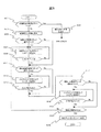
以下、図1から図11を参照して、本発明に係る実施の形態を説明する。この実施の形態は、銀行システムなどの金融機関システムに採用される例えばATM(Automatic Teller Machine)のような自動取引装置に関する。図1はATMの概略構造図、図2は銀行システムのネットワーク構成図、図3、図4が振り込み工程の動作フロー図、図5から図11が取引画面図である。 Embodiments according to the present invention will be described below with reference to FIGS. This embodiment relates to an automatic transaction apparatus such as an ATM (Automatic Teller Machine) employed in a financial institution system such as a bank system. FIG. 1 is a schematic structural diagram of an ATM, FIG. 2 is a network configuration diagram of a bank system, FIGS. 3 and 4 are operation flow diagrams of a transfer process, and FIGS. 5 to 11 are transaction screen diagrams.
先ず、図1に示すATM1の概略説明図を参照して、本実施の形態に係るATMの概略構造を説明する。
First, the schematic structure of the ATM according to the present embodiment will be described with reference to the schematic explanatory diagram of the
図1において、符号1で総括的に示すのは、金融機関等のロビーなどに設置される自動取引装置である。本実施の形態では、自動取引装置1としてATMの例で説明する。自動取引装置1は、直方体の前面上方の一部分が側面から見てL字形に切り欠かれた開口部を有する本体筐体10と、L字形の開口部を塞ぐように配置され、側面から見てL字形に形成されたフロントパネル11とから構成されている。
In FIG. 1, what is generally indicated by
本体筐体10は、前面が開口したベース筐体12と、このベース筐体12の前面下方に設けられた板状の前面扉13と、ベース筐体12の背面に配置された板状の背面扉14とを有している。ベース筐体12は、各種の取引処理を行う機構部、例えば、図2に示す、タッチパネル付表示部220、カード部221、通帳明細印字部222、伝送制御部223、記憶装置部224、硬貨入出金部225、紙幣入出金部226、電源部227、センサ部228、制御部229等を内蔵している。タッチパネル付表示部220は情報の入力装置および出力装置としての機能を備えており、カード部221はIDカード212(図2参照)の読取装置および出力装置としての機能を備えている。そして、タッチパネル付表示部220の操作表示部15や各部の媒体口18、19、23、24や生体認証部の生体情報読取部22は、フロントパネル11から露出するように配置されている。
The
L字形のフロントパネル11は、本体正面の垂直面を形成するパネル部16と、水平面を構成するテーブル部17とを備えている。本実施形態では、垂直面を構成する前記パネル部16の中央に媒体口であるカード/明細票取扱口18や通帳取扱口19からなる媒体取扱部20が配置され、水平面を構成するテーブル部17の中央に操作表示部15、その両側にハンドセット21と生体認証部の生体情報読取部22が配置され、水平面と垂直面の角部には媒体口である紙幣挿入/排出口23と硬貨挿入/排出口24が並設されている。
The L-shaped front panel 11 includes a
本実施の形態の大きな特徴の1つは、操作工程の多い振込み工程において、操作表示部15に、送り手側表示領域510と、受け取り手側表示領域540と、送り手側表示領域510から受け取り手側表示領域540に向かって送られる内容を示す送信内容領域560とを備えた1つの振込み画面500で手続きを可能とした点にある。
One of the major features of the present embodiment is that, in the transfer process with many operation processes, the
即ち、この実施の形態に係る振込み画面500によれば、送り手側表示領域510と受け取り手側表示領域540とを左右に並べて配置され、この送り手側表示領域510と受け取り手側表示領域540との間に送り手側表示領域510から受け取り手側表示領域540に指示する矢印形状の送信内容領域560が表示される。このため、利用者は「送り手側」と「受け取り手側」と「送信内容」とが振込み画面500を見ただけで直感的に認識することができるので、誤操作や操作の分かり難さを軽減することができる。
That is, according to the
本実施の形態の他の大きな特徴の1つは、前記3つの領域510、540、560を、詳細情報を表示する内容表示領域と、この内容表示領域の詳細情報を変更または登録するための選択ボタンとを含んで構成した点にある。
Another major feature of the present embodiment is that the three
即ち、前記送り手側表示領域510は、送り手側と成る依頼人の詳細情報が表示される内容表示領域511と、変更ボタン512とを含んで構成される。前記内容表示領域511は、変更ボタン512を選択することで、この内容表示領域511の内容を変更することができる。
That is, the sender
また、前記受け取り手側表示領域540は、受け取り側と成る受取人の詳細情報が表示される内容表示領域541と、変更/登録ボタン542とを含んで構成される。この実施の形態では、初めて振込み手続き行う場合は、この内容表示領域541には項目名のみ表示され、変更/登録ボタン542は「登録」として表示され、2回目以降の振込み手続き行う場合は、この内容表示領域541には前回の入力内容が表示され、変更/登録ボタン542は「変更」として表示される。
The receiver
また、送信内容領域560は、金額表示領域561と変更/登録ボタン562とを含んで構成される。この実施の形態では、初めて振込み手続き行う場合は、金額表示領域561には「0円」と表示され、変更/登録ボタン562は「登録」として表示され、2回目以降の振込み手続き行う場合は、金額表示領域561には前回の入力内容が表示され、変更/登録ボタン562は「変更」として表示される。
The
この実施の形態によれば、夫々の内容表示領域に隣接して配置される変更ボタンまたは変更/登録ボタンを操作することで、簡単に詳細情報を変更したり新規に登録することができる。また、2回目以降であれば、前回の入力内容が表示されるので、同じ振込みを行う場合は便利である。 According to this embodiment, detailed information can be easily changed or newly registered by operating a change button or a change / registration button arranged adjacent to each content display area. Moreover, since it is the second time or later, the previous input content is displayed, so it is convenient to perform the same transfer.
以下、図2から図11を参照して、この実施の形態に係る金融機関システムを更に詳細に説明する。 Hereinafter, the financial institution system according to this embodiment will be described in more detail with reference to FIGS.
先ず、図2を参照して、このATM1が設置される銀行システムとATM1の装置構成を説明する。図2は銀行システムのネットワーク構成図である。この銀行システムでは、この銀行システムを統括するセンタ100に対して複数の営業店舗200や専門センタ350がネットワーク300で接続されている。前記営業店舗200には、店舗ネットワーク211を介して複数の機器が接続され、これら機器が前記ネットワーク300を介して前記センタ100や前記専門センタ350と接続され、この銀行システムを利用する顧客に対して各種の金融サービスを提供することができる。この他、この銀行システムには前記ネットワーク300を介して他の金融システムや各種のサービスサイトに接続することができる。
First, with reference to FIG. 2, the bank system in which this ATM1 is installed and the device configuration of the ATM1 will be described. FIG. 2 is a network configuration diagram of the bank system. In this bank system, a plurality of
前記センタ100は、HUBサーバ150を介して他の営業店舗200や専門センタ350と接続することで、銀行内の全ての情報を統括管理している。このHUBサーバ150は、ゲートウエイサーバを兼用するものであり、チャネル系APサーバ群を統括する統合チャネルサーバ110と、勘定系ホスト140と、各種の新商品情報データを備えた新商品サーバ130と、全ての顧客情報を統括的に管理する顧客情報管理サーバ116などが接続される。
The
統合チャネルサーバ110は、前記ネットワーク300を介して営業店舗200と接続されて、営業店舗200に各種の情報を提供する支援システムである。この統合チャネルサーバ110の統括下には、IBコンテンツデータを備えたIBサーバ111と、営業店のコンテンツデータを備えた営業店APサーバ112と、来店顧客情報データを備えた来店管理サーバ113と、商品のコンテンツデータを備えた商品情報サーバ114と、行員情報データを備えた行員管理サーバ115と、顧客情報データを備えた顧客管理サーバ120とを備えている。
The integrated
一方、営業店舗200は、店舗ネットワーク211を介して各種装置が接続されている。例えば、このシステムでは、ATM(現金自動預払機)1、顧客の店舗の出入りを管理する受付端末208、顧客の各種の相談に対応する相談端末207、顧客に各種の情報を提供する情報テーブル端末206、行員が顧客に対して相談や商談を薦める相談テーブル端末205、行員が顧客に対して各種サービスを行う窓口PC端末204、前記窓口PC端末204を支援する後方PC端末203、各種の金融関連装置からなる金融デバイス202、店舗内の各種情報を管理する営業店サーバ201、店舗内の無線通信や位置検知を行う店舗通信システム210などが設けられている。
On the other hand, various devices are connected to the
また、この銀行システムでは、顧客が所有する携帯端末213や、この銀行が顧客に提供するIDカード212などを介して各種の情報を提供することができる。
Further, in this bank system, various information can be provided via a
前記ATM1は、このATM1を統括する制御部229の統括の下、タッチパネル付表示部220、IDカード212やキャッシュカードなどの各種のカードに対して読み取りや書き込みを行うカード部221と、通帳の書き込みを行う通帳明細印字部222と、店舗ネットワーク211に接続するための伝送制御部223と、各種のデータを記憶する記憶装置部224と、硬貨入出金部225と、紙幣入出金部226と、電源部227と、センサ部228とを含んで構成される。
Under the control of the
また、この実施の形態では、このATM1のタッチパネル付表示部220に表示される前記振込み画面500などの取引画面を、このATM1内で生成して表示させることができる。この場合、制御部229がタッチパネル付表示部220の操作指示に基づいて、統合チャネルサーバ110から必要な取引データを収集するとともに、前記記憶装置224から所定の取引画面データを呼び出して取引フローに沿った取引画面を生成し、この生成した取引画面を前記タッチパネル付表示部220に表示しながら取引を進めるものである。
Moreover, in this embodiment, transaction screens, such as the said
一方、他の実施の形態として、統合チャネルサーバ110で生成した取引画面を呼び出してタッチパネル付表示部220に表示しながら取引を進めるようにしてもよい。この場合、制御部229は、ネットワーク300を介して統合チャネルサーバ110に接続するための端末機としての制御を主体に動作させる。このように、ATM1を統合チャネルサーバ110にアクセスするための端末機として動作させることにより、各種のデータを端末装置であるATM1に持つ必要が無いので、情報の集中化が実現できる。
On the other hand, as another embodiment, a transaction screen generated by the
以下の説明では、ATM1で振込み画面500を生成する実施例で説明するが、統合チャネルサーバ110で生成するようにしても良い。
In the following description, an example in which the
次に、図3から図5を参照してこの実施の形態の特徴的な振込み画面500の動作フローを主体に説明する。
Next, the operation flow of the
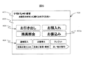
先ず、この実施の形態では、前記センサ部228を介して利用者がATM1に接近したことを検知すると、制御部229は、図5に示すメニュー画面400を前記記憶装置部224から読み出して操作表示部15に表示する。このメニュー画面400は、上下に2分割され、上部にガイダンス表示領域401、下部に複数の取引ボタン403,404が表示される選択ボタン表示領域402とを含んで構成される。選択ボタン表示領域402には、利用頻度の高い取引ボタン403が利用頻度の低い取引ボタン404より大きく表示されている。そして、ガイダンス表示領域401には「いらっしゃいませ。お取引のボタンに軽く手を触れてください」との操作を促すガイダンスが表示される。
First, in this embodiment, when it is detected that a user has approached
前記制御部229は、前記複数の取引ボタン403あるいは複数の取引ボタン404から1つの取引ボタンが選択されると、当該取引ボタンに対応する取引画面に移行する前に図6で示す認証画面410を表示する。ここでは、メニュー画面400において、「お振込み」の取引ボタン403aが選択されたとして、以下説明を行う。
When one transaction button is selected from the plurality of
図6において、認証画面410には、操作表示部15や各部の媒体口18、19、23、24を表したATM1の外観図411が表示され、媒体口18、19にカードと通帳を挿入するアニメーション412と操作ガイダンス413が表示されている。利用者が媒体口18にカード、または媒体口19に通帳を挿入すると、制御部229は、挿入されたカードまたは通帳から認証情報を読み取るとともに、暗証番号の入力を促す図7の暗証番号画面420を表示する。
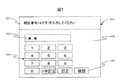
In FIG. 6, the
この暗証番号画面420は、上部に「暗証番号(4ケタ)を入力してください」との操作ガイダンスが表示されるガイダンス表示領域421が設けられ、その下部にはテンキー422と確認表示部423と確認キー424とを含んで構成される入力領域425を備えている。利用者がテンキー422で数値を入力すると、その内容が確認表示部423に表示される。そして確認キー424を選択することで、制御部229は、この入力された暗証番号とカードまたは通帳から読み込んだ認証情報との照合を行って、一致すれば、図8に示す振込み画面500を表示する。なお、暗証番号の入力において、本実施の形態では、暗証番号の入力後に確認キー424を操作することで認証を行うようにしているが、これに限定されるものではない。例えば、4ケタの暗証番号を入力する際、4ケタ目の数字を入力すると認証を開始するようにしてもよい。
This
以下、この振込み画面500の動作フローを図3、図4の動作フロー図に基づいて、図8から図12を参照して説明する。
Hereinafter, the operation flow of the
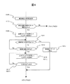
図3において、制御部229は、振込み画面500を表示するに当たり、前記統合チャネルサーバ110から利用者の利用状況のデータを入手して前回振込み手続きを行っているかを判定し(ステップ601)、振込み手続きを行っていれば、例えば、図10に示す前回振込み画面500Aを表示し(ステップ635)、振込み手続きを行っていなければ、図8に示す新規の振込み画面500を表示する(ステップ603)。なお、ステップ635において、前回振込み画面500Aが表示された後の動作フローについては後述する。
In FIG. 3, when displaying the
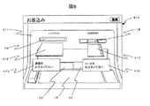
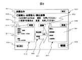
図8において、この新規の振込み画面500は、最上部に「振込み工程」であることを示すタイトルバー501が配置され、その下部に、操作のガイダンスを表示するガイダンス領域502が配置され、最下部に入力領域503が設定される。ガイダンス領域502には、例えば、「ご依頼人・お受取人・振込金額」「この内容でよければ「確認」を押してください」変更する場合は「変更」を押してください」とのガイダンスが表示される。
In FIG. 8, the
入力領域503には、送り手側表示領域510と受け取り手側表示領域540とが左右に並べて配置され、この2つの領域の間に送り手側表示領域510から受け取り手側表示領域540に指示する矢印形状の送信内容領域560が表示される。
In the
前記送り手側表示領域510は、送り手側と成る依頼人の詳細情報である「依頼人の氏名」と「連絡先となる電話番号」とこの依頼人の口座の「残高」がウインドウ形式で表示される内容表示領域511と、変更ボタン512が表示される。また、前記受け取り手側表示領域540は、受け取り側と成る受取人の詳細情報である「受取人」「金融機関」「支店名」「口座番号」の項目がウインドウ形式で表示される内容表示領域541と、変更/登録ボタン542が表示される。また、送信内容領域560は、送信する対象となる「振り込み金額」と「手数料」がウインドウ形式で表示される金額表示領域561と変更/登録ボタン562とが表示される。
In the sender
この新規の振込み画面500では、前回のデータがないので、受け取り手側表示領域540の内容表示領域541には項目名のみ表示されるとともに、変更/登録ボタン542が「登録」として表示される。また、同様に、送信内容領域560の「振り込み金額」の欄は「0円」と表示され、「手数料」の欄は空欄となり、更に、変更/登録ボタン562が「登録」として表示される。なお、「手数料」の欄には、振込み金額や振込先、振込み時間帯等の条件に基づいて制御部229が算出した手数料が表示されるようになっている。
In this
この他、この入力領域503の下方には、メニュー画面400に戻らせる前に戻るボタン504と、振込み手続きを実行させる確認ボタン505が設けられている。
In addition, a
さて、図3に戻り、制御部229は、図8の新規の振込み画面500を表示すると、依頼人の変更ボタン512が選択されたか(ステップ605)、振り込み金額の登録ボタン(変更/登録ボタン)562が選択されたか(ステップ611)、受取人の登録ボタン(変更/登録ボタン)542が選択されたか(ステップ617)を監視する。
Returning to FIG. 3, when the
新規の振込み画面500では、前回のデータが無いものの、送り手側表示領域510の内容表示領域511に表示される表示内容は、制御部229が統合チャネルサーバ110から読み取った口座所有者の内容を表示するので、通常は、変更ボタン512を操作することは無い。しかしながら、データの変更があれば、この変更ボタン512を選択することで、データの修正を行うことができる。また、受け取り手側表示領域540と送信内容領域560は、前回の入力データが無いので、変更/登録ボタン542、562を選択することで、これらの入力を行うことができる。
In the
この実施の形態では、変更ボタン512と変更/登録ボタン542、562が選択されると、制御部229は、図9に示すような、この振込み画面500に重ねて入力ウインドウ670を表示して、利用者の入力を受け付ける(ステップ607、613、619)。
In this embodiment, when the
図9において、入力ウインドウ670は、前記3つの内容表示領域511、541、561とは入力項目が異なるため、その入力キーのレイアウトや入力項目が若干異なるが、基本的には同様な書式で表示される。図9では、受け取り手側表示領域540における入力ウインドウ670を具体的に説明し、他の2つの入力ウインドウについては説明を省略する。
In FIG. 9, the
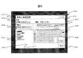
制御部229は、変更/登録ボタン542が選択されると、振込み画面500の明度を下げて、その上に入力ウインドウ670を表示する。この入力ウインドウ670は、上部に「受取人登録画面」の入力であることを示すタイトルバー671、その下部に操作のガイダンスを表示するガイダンス領域672が配置され、最下部に入力項目領域673と入力領域674が左右に分割して表示されている。
When the change /
入力項目領域673に表示される入力項目は、受け取り手側表示領域540の内容表示領域541に表示される入力項目と同じである。制御部229は、入力ウインドウ670を表示すると、入力項目領域673の最初の入力項目である「受取人」を活性化状態として、確認表示部675を表示するとともに、前記入力領域674には「受取人」の入力を可能とする入力キーボード部676を表示する。入力キーボード部676には、複数の入力キーからなる入力キーボード678と確認表示部677と確認キー679とが表示される。
The input items displayed in the
利用者が入力キーボード678から受取人の氏名を入力すると、その入力内容は、確認表示部677に表示され、確認キー679の選択で、確認表示部677の内容が入力項目領域673の確認表示部675に表示される。そして、再度、利用者が確認キー679を選択すると、「受取人」の入力項目が先の入力内容で固定されて非活性化状態となる。
When the user inputs the recipient's name from the input keyboard 678, the input content is displayed on the
そして、「受取人」の入力項目が確定すると次の「金融機関」を活性化状態として、確認表示部を表示するとともに、前記入力領域674には「金融機関」の入力を可能とする入力キーボード部を表示する。ここでは、先の「受取人」と同様な手続きであるため説明を省略する。
When the input item of “recipient” is confirmed, the next “financial institution” is activated and a confirmation display portion is displayed, and the
このように、この実施の形態に係る入力ウインドウ670は、入力項目領域673に表示される入力項目を順次、活性化状態として前記入力領域674からの入力を受け付けて最後の入力項目の確定を持って受け取り手側表示領域540の登録を受け付け、入力ウインドウ670を閉じて、操作表示部15の表示内容を図10で示すように、入力内容が反映した振込み画面500に戻す(ステップ621)。このような手続きは、送り手側表示領域510と内容表示領域541での入力ウインドウでの入力受付でも同じである(ステップ609、615)。
As described above, the
この入力ウインドウでの受付では、入力項目領域673での入力項目の選択に対応して入力領域674の入力キーボード部の内容が予め設定された最適なものが表示され、更に、ガイダンス領域672での操作ガイダンスも、これら入力手続きに対応したガイダンスが表示される。
In the reception in this input window, the optimum one in which the contents of the input keyboard portion of the
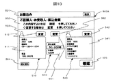
次に、図3のステップ601において、利用者が前回振込み手続きを行っていると、制御部229は統合チャンネルサーバ110から取得したデータ、例えば、図10に示す前回振込み画面500Aを表示する。この前回振込み画面500Aでは内容表示領域511と内容表示領域541に前回の入力データが表示され、変更/登録ボタン542と変更/登録ボタン562が「変更」に表示されている。この状態で、例えば、変更/登録ボタン542が選択されると、制御部229は、前回振込み画面500Aに図11で示す選択ウインドウ680を表示する。この選択ウインドウ680の動作フローを図4に示す。
Next, in
図4及び図11において、制御部229は、変更/登録ボタン542が選択されると(ステップ637)、振込み画面500Aの明度を下げて、その上に選択ウインドウ680を表示し、この選択ウインドウ680での選択を受け付ける(ステップ639)。なお、ステップ637において、変更/登録ボタン542が選択されなかった場合、制御部229は、登録内容に変更が無いものと判断し、ステップ623に至って処理を行う。
4 and 11, when the change /
この選択ウインドウ680は、過去に振り込んだ受取人の選択ボタン681と新規登録ボタン682及び「とじる」ボタン683が表示されている。選択ボタン681には受取人の氏名や銀行、支店名などが表示されている。制御部229は、既に登録された前記選択ボタン681が選択されているか(ステップ641)、あるいは新規登録ボタン682が選択されたか(ステップ643)を監視している。前記選択ボタン681の何れか1つが選択されると、この選択ウインドウ680を閉じて図10で示す前回振込み画面500Aの画面に戻すとともに、内容表示領域541の表示内容を前記登録済みデータに修正する(ステップ649)。
In this
一方、新規登録ボタン682が選択されると、制御部229は、前記ステップ619、621と同様に、入力ウインドウ670を表示して入力データを受付(ステップ645)、入力が完了しているか否かを判定して(ステップ647)、ステップ623に至る。ここで、この実施の形態では、選択ウインドウ680の表示形式を選択ボタン形式としたが、リスト形式で表示してもよい。
On the other hand, when the
また、この実施の形態では、図10において、変更/登録ボタン562が選択された場合、制御部229は、前回振込み画面500Aに図示しない金額入力画面(金額変更ウインドウ)を表示し、図4と同様な動作を実行することで、振り込み金額を入力するようになっている。
Further, in this embodiment, when the change /
以上述べたように、この実施の形態に係る振込み画面500によれば、受け取り手側表示領域540に対して、送り手側表示領域510から送信内容領域560の内容が送られることが模式的に明確に表現されていることから、利用者が、その手続きを感覚的に把握することができるから、誤操作を軽減することができる。しかも、3つの領域を選択することで、当該領域の内容を変更したり新規に登録することができるので、その修正や新規登録を感覚的に把握することができるので、入力時の誤操作が軽減される。しかも、前回のデータを再利用することもできる。
As described above, according to the
なお、前記実施の形態では、変更ボタンや変更/登録ボタンを設けて、これらボタンの選択でデータの修正や新規登録を行うようにしたが、これらボタンに代えて、内容表示領域自体を選択するようにしても良い。 In the above embodiment, the change button and the change / registration button are provided, and data correction and new registration are performed by selecting these buttons. Instead of these buttons, the content display area itself is selected. You may do it.
1…ATM、10…本体筐体、11…フロントパネル、12…ベース筐体、13…前面扉、14…背面扉、15…操作表示部、16…パネル部、17…テーブル部、18…カード/明細票取扱口、19…通帳取扱口、20…媒体取扱部、21…ハンドセット、22…生体情報読取部、23…紙幣挿入/排出口、24…硬貨挿入/排出口、100…センタ、110…統合チャネルサーバ、111…IBサーバ、112…営業店APサーバ、113…来店管理サーバ、114…商品情報サーバ、115…行員管理サーバ、116…顧客情報管理サーバ、120…顧客管理サーバ、130…新商品サーバ、140…勘定系ホスト、150…HUBサーバ、200…営業店舗、201…営業店サーバ、202…金融デバイス、203…後方PC端末、204…窓口PC端末、205…相談テーブル端末、206…情報テーブル端末、207…相談端末、208…受付端末、210…店舗通信システム、211…店舗ネットワーク、212…IDカード、213…携帯端末、220…タッチパネル付表示部、221…カード部、222…通帳明細印字部、223…伝送制御部、224…記憶装置部、225…硬貨入出金部、226…紙幣入出金部、227…電源部、228…センサ部、229…制御部、300…ネットワーク、350…専門センタ、400…メニュー画面、401…ガイダンス表示領域、402…表示領域、403…取引ボタン、404…取引ボタン、410…認証画面、420…暗証番号画面、421…ガイダンス表示領域、422…テンキー、423…確認表示部、424…確認キー、425…入力領域、500…振込み画面、501…タイトルバー、502…ガイダンス領域、503…入力領域、504…戻るボタン、505…確認ボタン、510…送り手側表示領域、511…内容表示領域、512…変更ボタン、540…受け取り手側表示領域、541…内容表示領域、542…変更/登録ボタン、560…送信内容領域、561…金額表示領域、562…変更/登録ボタン、670…入力ウインドウ、671…タイトルバー、672…ガイダンス領域、673…入力項目領域、674…入力領域、675…確認表示部、676…入力キーボード部、677…確認表示部、678…入力キーボード、679…確認キー、680…選択ウインドウ、681…選択ボタン、682…新規登録ボタン。
DESCRIPTION OF
Claims (4)
前記表示装置の操作画面に、送り手側表示領域と、受け取り手側表示領域と、送り手側表示領域から受け取り手側表示領域に向かって送られる内容を示す送信内容領域とを備えた1つの振込み画面を表示する
ことを特徴とする自動取引装置。 In an automatic transaction apparatus that is connected to a host computer via a communication line and displays an operation screen of various transactions on the display screen of the display device to perform the transaction,
One operation screen of the display device is provided with a sender-side display area, a receiver-side display area, and a transmission content area indicating contents transmitted from the sender-side display area toward the receiver-side display area. An automatic transaction apparatus characterized by displaying a transfer screen.
前記送り手側表示領域と前記受け取り手側表示領域と前記送信内容領域を、詳細情報を表示する内容表示領域と、この内容表示領域の詳細情報を変更または登録するための選択ボタンとを含んで構成した
ことを特徴とする自動取引装置。 The automatic transaction apparatus according to claim 1,
The sender-side display area, the receiver-side display area, and the transmission content area include a content display area for displaying detailed information, and a selection button for changing or registering the detailed information in the content display area. An automatic transaction apparatus characterized by comprising.
該自動取引装置は、制御装置を備え、該制御装置は、過去の取引の有無を前記ホストコンピュータから取得し、前記受け取り手側表示領域の前記内容表示領域に取得したデータを表示する
ことを特徴とする自動取引装置。 The automatic transaction apparatus according to claim 2,
The automatic transaction apparatus includes a control device, the control device acquires presence / absence of a past transaction from the host computer, and displays the acquired data in the content display area of the receiver side display area. Automatic transaction equipment.
前記制御装置は、前記受け取り手側表示領域の前記選択ボタンの操作にともなって、
複数の過去の取引のデータを選択させるウインドウを表示する
ことを特徴とする自動取引装置。 The automatic transaction apparatus according to claim 3,
With the operation of the selection button in the receiver side display area, the control device,
An automatic transaction apparatus characterized by displaying a window for selecting a plurality of past transaction data.
Priority Applications (1)
| Application Number | Priority Date | Filing Date | Title |
|---|---|---|---|
| JP2007078137A JP5372334B2 (en) | 2007-03-26 | 2007-03-26 | Automatic transaction equipment |
Applications Claiming Priority (1)
| Application Number | Priority Date | Filing Date | Title |
|---|---|---|---|
| JP2007078137A JP5372334B2 (en) | 2007-03-26 | 2007-03-26 | Automatic transaction equipment |
Publications (2)
| Publication Number | Publication Date |
|---|---|
| JP2008242547A true JP2008242547A (en) | 2008-10-09 |
| JP5372334B2 JP5372334B2 (en) | 2013-12-18 |
Family
ID=39913862
Family Applications (1)
| Application Number | Title | Priority Date | Filing Date |
|---|---|---|---|
| JP2007078137A Expired - Fee Related JP5372334B2 (en) | 2007-03-26 | 2007-03-26 | Automatic transaction equipment |
Country Status (1)
| Country | Link |
|---|---|
| JP (1) | JP5372334B2 (en) |
Citations (8)
| Publication number | Priority date | Publication date | Assignee | Title |
|---|---|---|---|---|
| JPH03260894A (en) * | 1990-03-12 | 1991-11-20 | Hitachi Ltd | Guidance control method for automatic cash transaction machine |
| JPH0540773A (en) * | 1991-08-02 | 1993-02-19 | Hitachi Ltd | Automatic transfer machine |
| JPH0644286A (en) * | 1992-03-27 | 1994-02-18 | Hitachi Ltd | Automatic transaction machine |
| JPH07296087A (en) * | 1994-04-22 | 1995-11-10 | Fujitsu Ltd | Automatic transaction device |
| JPH09223258A (en) * | 1996-02-19 | 1997-08-26 | Fujitsu Ltd | Automatic transfer device |
| JPH10334158A (en) * | 1997-05-30 | 1998-12-18 | Fujitsu Ltd | Transfer transaction system |
| JP2000149097A (en) * | 1998-11-18 | 2000-05-30 | Toshiba Corp | Automatic transaction device and control method therefor |
| JP2006350582A (en) * | 2005-06-15 | 2006-12-28 | Oki Electric Ind Co Ltd | Automatic transaction device |
-
2007
- 2007-03-26 JP JP2007078137A patent/JP5372334B2/en not_active Expired - Fee Related
Patent Citations (8)
| Publication number | Priority date | Publication date | Assignee | Title |
|---|---|---|---|---|
| JPH03260894A (en) * | 1990-03-12 | 1991-11-20 | Hitachi Ltd | Guidance control method for automatic cash transaction machine |
| JPH0540773A (en) * | 1991-08-02 | 1993-02-19 | Hitachi Ltd | Automatic transfer machine |
| JPH0644286A (en) * | 1992-03-27 | 1994-02-18 | Hitachi Ltd | Automatic transaction machine |
| JPH07296087A (en) * | 1994-04-22 | 1995-11-10 | Fujitsu Ltd | Automatic transaction device |
| JPH09223258A (en) * | 1996-02-19 | 1997-08-26 | Fujitsu Ltd | Automatic transfer device |
| JPH10334158A (en) * | 1997-05-30 | 1998-12-18 | Fujitsu Ltd | Transfer transaction system |
| JP2000149097A (en) * | 1998-11-18 | 2000-05-30 | Toshiba Corp | Automatic transaction device and control method therefor |
| JP2006350582A (en) * | 2005-06-15 | 2006-12-28 | Oki Electric Ind Co Ltd | Automatic transaction device |
Also Published As
| Publication number | Publication date |
|---|---|
| JP5372334B2 (en) | 2013-12-18 |
Similar Documents
| Publication | Publication Date | Title |
|---|---|---|
| JP5099986B2 (en) | Automatic transaction equipment | |
| JP2008204409A (en) | Password input display device and method | |
| JP5121607B2 (en) | Automatic transaction apparatus and system, and information recording medium | |
| JP4997871B2 (en) | Automatic transaction equipment | |
| KR101495657B1 (en) | Method for providing financial service using a hybrid ATM | |
| JP4706346B2 (en) | Automatic transaction equipment | |
| JP5505397B2 (en) | Automatic transaction equipment | |
| JP2008191945A (en) | Transfer transaction system | |
| JP5104167B2 (en) | Window business processing system | |
| JP5372334B2 (en) | Automatic transaction equipment | |
| JP4654002B2 (en) | Information display device | |
| JP4682631B2 (en) | Automatic transaction equipment | |
| KR20070070575A (en) | Atm system for providing custom-made ui display | |
| JP2008242546A (en) | Information processor | |
| JP2012003559A (en) | Automatic transaction device and automatic transaction system | |
| JP2008242545A (en) | Automatic transaction device | |
| JP2006134011A (en) | Automatic transaction machine | |
| JP2006031355A (en) | System for notifying taking-in of medium left by forgetting | |
| JP5055935B2 (en) | Automatic transaction system and automatic transaction device | |
| JP2008242784A (en) | Automatic transaction device and automatic transaction system | |
| JP4403814B2 (en) | Automatic cash transaction apparatus and system using the same | |
| JP2005115679A (en) | Automatic transaction device | |
| JPH10261133A (en) | Automatic transaction device and its control method | |
| JP2007087315A (en) | Automatic transaction system | |
| KR20090047308A (en) | A drawing menu of auto teller machine |
Legal Events
| Date | Code | Title | Description |
|---|---|---|---|
| A621 | Written request for application examination |
Free format text: JAPANESE INTERMEDIATE CODE: A621 Effective date: 20100308 |
|
| A521 | Request for written amendment filed |
Free format text: JAPANESE INTERMEDIATE CODE: A523 Effective date: 20100308 |
|
| A977 | Report on retrieval |
Free format text: JAPANESE INTERMEDIATE CODE: A971007 Effective date: 20120628 |
|
| A131 | Notification of reasons for refusal |
Free format text: JAPANESE INTERMEDIATE CODE: A131 Effective date: 20120703 |
|
| A521 | Request for written amendment filed |
Free format text: JAPANESE INTERMEDIATE CODE: A523 Effective date: 20120831 |
|
| A521 | Request for written amendment filed |
Free format text: JAPANESE INTERMEDIATE CODE: A523 Effective date: 20120831 |
|
| A02 | Decision of refusal |
Free format text: JAPANESE INTERMEDIATE CODE: A02 Effective date: 20130219 |
|
| A521 | Request for written amendment filed |
Free format text: JAPANESE INTERMEDIATE CODE: A523 Effective date: 20130517 |
|
| A521 | Request for written amendment filed |
Free format text: JAPANESE INTERMEDIATE CODE: A523 Effective date: 20130517 |
|
| A911 | Transfer to examiner for re-examination before appeal (zenchi) |
Free format text: JAPANESE INTERMEDIATE CODE: A911 Effective date: 20130606 |
|
| TRDD | Decision of grant or rejection written | ||
| A01 | Written decision to grant a patent or to grant a registration (utility model) |
Free format text: JAPANESE INTERMEDIATE CODE: A01 Effective date: 20130820 |
|
| A61 | First payment of annual fees (during grant procedure) |
Free format text: JAPANESE INTERMEDIATE CODE: A61 Effective date: 20130918 |
|
| R150 | Certificate of patent or registration of utility model |
Free format text: JAPANESE INTERMEDIATE CODE: R150 |
|
| LAPS | Cancellation because of no payment of annual fees |