JP2008231799A - Base isolation structure - Google Patents
Base isolation structure Download PDFInfo
- Publication number
- JP2008231799A JP2008231799A JP2007073755A JP2007073755A JP2008231799A JP 2008231799 A JP2008231799 A JP 2008231799A JP 2007073755 A JP2007073755 A JP 2007073755A JP 2007073755 A JP2007073755 A JP 2007073755A JP 2008231799 A JP2008231799 A JP 2008231799A
- Authority
- JP
- Japan
- Prior art keywords
- seismic isolation
- ring
- pile head
- isolation structure
- lower structural
- Prior art date
- Legal status (The legal status is an assumption and is not a legal conclusion. Google has not performed a legal analysis and makes no representation as to the accuracy of the status listed.)
- Pending
Links
Images


Abstract
Description
本発明は、杭頭部に設けた免震装置により建物の免震を達成する免震構造に関する。 The present invention relates to a seismic isolation structure that achieves seismic isolation of a building by a seismic isolation device provided at a pile head.
従来の杭頭部を利用した免震構造は、該杭頭部に極厚のマットスラブ或いはスラブ付き基礎梁を形成することにより下部構造を構成し、該杭頭部における接合部を可能な限り剛構造とし、該杭頭部の回転角が少なくなるようにしていた。特に軟弱地盤における免震構造では、杭の水平変位及び回転角が過大となる傾向があり、より一層、該杭頭部と下部構造との接合部を剛構造とする必要があった。 The conventional seismic isolation structure using the pile head is composed of an extremely thick mat slab or foundation beam with slab on the pile head to form the lower structure, and as much as possible the joint in the pile head A rigid structure was adopted so that the rotation angle of the pile head was reduced. In particular, in the seismic isolation structure in soft ground, the horizontal displacement and rotation angle of the pile tend to be excessive, and it is necessary to make the joint between the pile head and the lower structure more rigid.
一方、先行技術となる特開2006−249784号公報及び特開2006−104883号公報に開示されている下部構造にあっては、該下部構造から極厚のマットスラブや基礎梁を省略し、杭頭部に免震装置を直接載せる杭頭部免震構造を採用している。 On the other hand, in the lower structure disclosed in Japanese Patent Application Laid-Open No. 2006-249784 and Japanese Patent Application Laid-Open No. 2006-104883 which are prior arts, an extremely thick mat slab or foundation beam is omitted from the lower structure, A pile head seismic isolation structure is used, in which the seismic isolation device is placed directly on the head.
また、他の先行技術となる特開平9−273162号公報の杭頭部に係わる下部構造では、該杭頭部の回転拘束をなくしてピン支承(半固定化)とする技術が開示されている。
上記従来の杭頭部に係わる下部構造における剛構造は、接合部の固定度が高くなりすぎ、杭頭部付近の曲げ応力が極端に増大し、それにより杭頭部の損傷も生じ易くなり、構造性能の低下に繋がりかねないおそれがあった。しかも、極厚のマットスラブ或いはスラブ付き基礎梁を形成するための材料費及び施工費が嵩み、コスト及び工期的にも大きな問題があった。 The rigid structure in the lower structure related to the above-mentioned conventional pile head, the fixing degree of the joint becomes too high, the bending stress in the vicinity of the pile head is extremely increased, and it is easy to cause damage to the pile head, There was a risk that structural performance could be degraded. In addition, the material cost and the construction cost for forming the extremely thick mat slab or the foundation beam with the slab are increased, and there are significant problems in terms of cost and construction period.
また、先行技術となる上記特開2006−249784号公報及び特開2006−104883号公報に開示された杭頭部の免震構造は、免震装置の設置位置が杭頭部が施工される設置精度に直接影響を受けることになり、杭の施工管理が非常に難しくなる欠点があった。更に、先行技術の上記特開平9−273162号公報に開示されたものは、杭頭部と底盤とがダボ筋によってのみ接合されており、杭頭部の回転に伴って接合部分への損傷が発生するおそれがあり、構造性能の著しい低下が想定される欠点があった。 Moreover, the pile head seismic isolation structure disclosed in the above Japanese Patent Laid-Open Nos. 2006-249784 and 2006-104883, which is the prior art, is installed in which the pile head is installed at the position where the seismic isolation device is installed. There is a drawback that pile management is very difficult because it is directly affected by accuracy. Further, in the prior art disclosed in Japanese Patent Laid-Open No. 9-273162, the pile head and the base are joined only by the dowel bar, and the damage to the joined portion is caused by the rotation of the pile head. There is a possibility that it may occur, and there is a drawback that a significant decrease in structural performance is assumed.
本発明は、上記欠点を解決したもので、杭頭部の上にプレキャスト部材を介して免震装置を設置すること及びその免震装置の据え付け手段の簡略化を図ることにより、下部構造における免震構造のコスト及び工期の低減を達成したものである。 The present invention solves the above-mentioned drawbacks. By installing a seismic isolation device on a pile head via a precast member and simplifying the installation means of the seismic isolation device, The cost of the seismic structure and the construction period have been reduced.
本発明の免震構造は、杭頭部の先端周縁部に該周縁部よりその一部が上方へ突出するようにしてプレキャストコンクリート製リングが設置され、該プレキャストコンクリート製リング上には建物の下部構造材を該リングと一体となるように構成し、該下部構造材と上方の構造物との間に免震装置を固定してなる免震構造を特徴とする。 In the seismic isolation structure of the present invention, a ring made of precast concrete is installed at the tip periphery of the pile head so that a part thereof protrudes upward from the periphery, and the lower part of the building is placed on the precast concrete ring. The structure material is configured to be integrated with the ring, and is characterized by a seismic isolation structure in which a seismic isolation device is fixed between the lower structure material and an upper structure.
また、免震装置は、下部構造材の上面に設けた複数個の係止手段へアンカーボルトを挿入固定することにより該下部構造材と固定してなる免震構造を特徴とする。 The seismic isolation device is characterized by a seismic isolation structure that is fixed to the lower structural member by inserting and fixing anchor bolts to a plurality of locking means provided on the upper surface of the lower structural member.
更に、下部構造材をPCa部材とした免震構造を特徴とする。 Furthermore, it features a seismic isolation structure in which the lower structural material is a PCa member.
また、隣接する下部構造材相互をつなぎ梁によって連結一体化した免震構造を特徴とする。 It also features a seismic isolation structure in which adjacent lower structural members are connected and integrated by connecting beams.
更に、下部構造材とつなぎ梁はプレストレスを導入されたPC鋼線により一体化してなる免震構造を特徴とする。 Furthermore, the substructure material and the connecting beam are characterized by a seismic isolation structure in which prestressed PC steel wires are integrated.
杭頭部にプレキャスト部材であるPCリングを設置することにより、杭の設置位置やレベル等に施工精度上のバラツキが生じてもその誤差を吸収することができ、芯及びレベルを出すことが容易となったと同時に、下部構造材をプレキャスト化することにより省力化された免震構造を得ることが可能となった。 By installing the PC ring, which is a precast member, on the pile head, it is possible to absorb the error even if the pile installation position or level varies, and the core and level can be easily obtained. At the same time, it became possible to obtain a labor-saving seismic isolation structure by precasting the lower structural material.
また、複数の杭頭部におけるPCリング上の下部構造材としてPCa部材を設置し、該PCa部材相互をつなぎ梁で連結する構造としたことにより、各々の位置での水平変位を同一とすることができ、振動に対して安定した免震構造を得ることが可能となった。 In addition, by installing a PCa member as a lower structural material on the PC ring in a plurality of pile heads and connecting the PCa members with a connecting beam, the horizontal displacement at each position is the same. It was possible to obtain a seismic isolation structure that was stable against vibration.
更に、下部構造材においてアンボンドPC鋼線によりプレストレスを導入することにより、より一層強固に杭頭部の水平変位を抑制することが可能となった。 Furthermore, it became possible to suppress the horizontal displacement of the pile head more firmly by introducing pre-stress in the substructure material with the unbonded PC steel wire.
また、杭頭部を半固定とすることにより、下部構造材に生じる曲げ応力は従来のマットスラブや基礎梁に比べて少なく、それによりつなぎ梁の断面積を小さくすることが可能となった。 In addition, by making the pile head semi-fixed, the bending stress generated in the lower structural material is less than that of conventional mat slabs and foundation beams, which makes it possible to reduce the cross-sectional area of the connecting beam.
更に、下部構造材を簡素化することにより、コスト及び工期を大幅に低減することが可能となった。 Furthermore, by simplifying the lower structural material, it has become possible to significantly reduce the cost and construction period.
また、免震装置を交換する際は、上部構造となる梁と下部構造材としてのPCa部材の盤面との間にジャッキ装置を設置して操作をすることにより、上部構造の荷重を安定的に下部構造に伝達させることが可能となった。 In addition, when exchanging the seismic isolation device, it is possible to stably load the upper structure by installing a jack device between the beam that becomes the upper structure and the panel surface of the PCa member as the lower structure material. It became possible to transmit to the substructure.
本発明の免震構造について、その実施例を以下に説明する。 Examples of the seismic isolation structure of the present invention will be described below.
図1は、所定箇所に形成された杭の杭頭部1の側断面図を示したもので、場所打ち杭、鋼管杭或いはコンクリート杭等の様々な杭頭部1が想定される様々な杭の内、既製コンクリート杭の場合を示したもので、該杭頭部1は先端となる杭頭部を削り(斜線部分)、杭主筋2が杭頭部1に露出するようにし、その露出した杭主筋2にフープ筋3をセットして固定し、杭頭部1の補強をする。
FIG. 1 shows a side sectional view of a
次に、図2に示すように、杭が設置された杭頭部1の周辺の土を所定深さに掘り削って杭頭部1を表面土より露出させ、該削り除いた後の表面土上に砂利4を敷き詰めて転圧する。更に、該敷砂利4上には水平レベルを出すための捨コンクリート5を打設し、表面側を平滑面6とする。
Next, as shown in FIG. 2, the soil around the
上記により、平滑面6は杭頭部1の天端より下がった位置に形成されることになる。上記杭頭部1の上端周縁部には天端レベルプレート7を装着しているが、該周縁部には該天端レベルプレート7上で且つ杭頭部1の周縁部から外方に突出するようにしてPCリング受けスペーサー8を適数個固定する。上記杭頭部1の上端周辺位置となる上記捨コンクリート5の平滑面6上には、図3に示すプレキャストコンクリート製でリング状に形成したプレキャストコンクリート製リング(以下、PCリングという)9を杭頭部1を囲むようにして載置する。該PCリング9にはその下面にレベルを調整するためのレベル調整用インサート10を設けている。
As a result, the
上記PCリング9は、杭頭部1の周辺部の平滑面6上に、その内周壁をPCリング受けスペーサー8に接するようにして載置し、レベル調整用インサート10によりレベルを調整し、レベルが得られた段階で平滑面6上の該PCリング9の下部側となる位置にモルタル11を打設し、該PCリング9を平滑面6上に固定する。
The
上記PCリング9は、鋼板リングに多数の縦筋を取着し、高強度せん断補強筋をスパイラル状に取り囲んでかご状の配筋となる補強材を形成し、該補強材にコンクリートを打ち込んでリング状に形成したもので、該縦筋の上方側をコンクリートより露出させて定着筋12としている。上記のようにPCリング9を平滑面6上に固定することによりPCリング受けスペーサー8の下方部となる杭頭部1外周部とPCリング9の内側壁との間に空間が形成されるが、該空間には目地処理としてモルタル13を充填する。上記によりPCリング9が杭頭部1と一体的に構成されることになる。
The
PCリング9が設置固定された後、上記捨コンクリート5の表面上に該PCリング9の上端部のレベルが強固に保持されるように、該PCリング9の上端部となる位置まで捨コンクリート14を打設する。
After the
該PCリング9上及び打設後の上記捨コンクリート14上には、図4に示すように、PCa部材15を載置する。該PCa部材15は、杭頭部1と該PCa部材15とを一体化させるためにその中央部にコンクリート打設用の大径孔16を形成し、その周縁部には上記PCリング9の定着筋12が挿入されるスパイラルシースを打ち込んだ複数の挿入孔17を形成し、更に、該PCa部材15と他の部材とをその端部方向において連結するための複数の挿入孔18、上面において免震ゴムを受けるフランジ板を固定するための袋ナット等の複数の係止手段19及びテンプレート20等が予め形成されている。
As shown in FIG. 4, a PCa
上記PCリング9の複数の定着筋12をPCa部材15の複数の挿入孔17へ挿入することにより、PCa部材を所定位置に載置することができ、該挿入孔17内にモルタル21を充填することにより両者を固定することができる。また、PCa部材15の中央部の大径孔16となる貫通孔には、上記PCa部材15の載置固定後、該大径孔16より杭頭部1上方の空間部22及び該大径孔16へ中詰めコンクリート23を打設する。
By inserting the plurality of
中詰めコンクリート23を打設し、その硬化後、大径孔16をふさぐようにしてフランジ板24をPCa部材15上に載置し、フランジ板24の周縁部の孔よりアンカーボルト25をテンプレート20及び係止手段19へ挿入係止することによってPCa部材15上にフランジ板24を固定する。
After placing the filling
該フランジ板24上にはゴム板と硬質板との積層体とした免震ゴム体26よりなる免震装置を載置固定し、その最上端部には他のフランジ板27を設け、上部構造体となる基礎構造物28とアンカーボルト29により固定する
On the
図5は、他の実施例を示したもので、削りの必要のない既製杭にPCリング9´を装着した実施例である。既製杭の周辺部は上記実施例1と同様に、砂利4´を敷き詰め、捨コンクリート5´を打設し、平滑面6´を形成している。杭頭部1´の周縁部には端部から外方へ突出するようにしてPCリング受けスペーサー8´を適数個固定する。上記捨コンクリート5´の平滑面6´上にPCリング9´を上記PCリング受けスペーサー8´を内接させながら、その上端部が水平となるようにレベルを調整して固定する。その後のPCa部材の取り付けや免震装置及び基礎構造物の施工は、上記実施例1と同様である。
FIG. 5 shows another embodiment, which is an embodiment in which a PC ring 9 'is mounted on a ready-made pile that does not require cutting. The peripheral part of the ready-made pile is spread with gravel 4 'and casted concrete 5' to form a smooth surface 6 ', as in Example 1. An appropriate number of PC
上記PCa部材15は、同様のPCa部材や他の部材とPCa部材15の複数の挿入孔18を介して連結することができる。この実施例では現場打ちとなるつなぎ梁30により隣接するPCa部材15相互を連結している。鉄筋31の端部を挿入孔18へ挿入し、隣接するPCa部材15間に所定の配筋を施工した後、コンクリート32を打設することによりPCa部材15相互を連結するためのつなぎ梁30を形成することができる。
The
図6は、他の実施例を示したもので、PCa部材15´の板面方向に沿って貫通するシース管33を予め埋設配置したものである。該シース管33は、縦方向及び横方向に貫通配設できるように井型状に設けている。
FIG. 6 shows another embodiment, in which a
上記PCa部材15´に隣接してPCa部材15´間につなぎ梁30´を構成することになるが、該つなぎ梁30´中にも上記シース管33と一直線となるように他のシース管34を埋設配置する。
A connecting
PCリング9上に上記PCa部材15´の設置及びその隣接位置となるつなぎ梁30´等において所定の配筋が終了した後、つなぎ梁30´等を構成する現場対応の位置にコンクリートを打設することになる。上記シース管33、34内にはアンボンドPC鋼線35を配置し、該アンボンドPC鋼線35にプレストレスを導入することにより、PCa部材15´とつなぎ梁30´とが強固に連結されることになる。
After the PCa member 15 'is installed on the
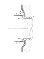
図7(a)及び図7(b)は、PCa部材15´とつなぎ梁30´とをアンボンドPC鋼線35によりプレストレスをかけて連結した状態を示す正断面図及び側断面図である。
FIGS. 7A and 7B are a front sectional view and a side sectional view showing a state in which the
上記実施例4では、下部構造材としてPCa部材15´を使用しているが、PCリングを設置し、その周辺部に捨コンクリートを打設した後、その上面側に配筋及びシース管等を設置し、コンクリートを打設することにより下部構造材及びつなぎ梁を構成することも可能である。その際、シース管内にアンボンドPC鋼線を挿入してプレストレスをかけることは上記実施例と同様である。 In Example 4 above, the PCa member 15 'is used as the lower structural material, but after installing the PC ring and placing the discarded concrete around the PC ring, reinforcement and a sheath tube are placed on the upper surface side. It is also possible to configure the lower structural material and the connecting beam by installing and placing concrete. At that time, the pre-stress is applied by inserting an unbonded PC steel wire into the sheath tube as in the above embodiment.
1、1´ 杭頭部
2 杭主筋
3 フープ筋
4、4´ 砂利
5、5´、14 捨コンクリート
6、6´ 平滑面
7 天端レベルプレート
8、8´ PCリング受けスペーサー
9、9´ PCリング
10 レベル調整用インサート
11、13、21 モルタル
12 定着筋
15、15´ 下部構造材
16 大径孔
17、18 挿入孔
19 係止手段
20 テンプレート
22 空間部
23 中詰めコンクリート
24、27 フランジ板
25、29 アンカーボルト
26 免震ゴム体
28 基礎構造物
30、30´ つなぎ梁
31 鉄筋
32 コンクリート
33、34 シース管
35 アンボンドPC鋼線
1, 1 '
Claims (5)
Priority Applications (1)
| Application Number | Priority Date | Filing Date | Title |
|---|---|---|---|
| JP2007073755A JP2008231799A (en) | 2007-03-21 | 2007-03-21 | Base isolation structure |
Applications Claiming Priority (1)
| Application Number | Priority Date | Filing Date | Title |
|---|---|---|---|
| JP2007073755A JP2008231799A (en) | 2007-03-21 | 2007-03-21 | Base isolation structure |
Publications (1)
| Publication Number | Publication Date |
|---|---|
| JP2008231799A true JP2008231799A (en) | 2008-10-02 |
Family
ID=39904931
Family Applications (1)
| Application Number | Title | Priority Date | Filing Date |
|---|---|---|---|
| JP2007073755A Pending JP2008231799A (en) | 2007-03-21 | 2007-03-21 | Base isolation structure |
Country Status (1)
| Country | Link |
|---|---|
| JP (1) | JP2008231799A (en) |
Cited By (9)
| Publication number | Priority date | Publication date | Assignee | Title |
|---|---|---|---|---|
| JP4934769B1 (en) * | 2011-06-14 | 2012-05-16 | Glプロパティーズ株式会社 | Seismic isolation device with rotation control spring mechanism and method of controlling rotation amount of seismic isolation device |
| JP2013087438A (en) * | 2011-10-14 | 2013-05-13 | Kurosawa Construction Co Ltd | Base-isolated structure |
| JP2013129988A (en) * | 2011-12-21 | 2013-07-04 | Shinsei Komu:Kk | Compaction jig and compaction method of ground |
| JP2014020027A (en) * | 2012-07-13 | 2014-02-03 | Kumagai Gumi Co Ltd | Pile foundation structure |
| JP2015200094A (en) * | 2014-04-07 | 2015-11-12 | 株式会社竹中工務店 | footing foundation structure |
| JP2016084703A (en) * | 2016-02-16 | 2016-05-19 | 株式会社新生工務 | Compaction jig and subsoil compaction method |
| JP2017036608A (en) * | 2015-08-11 | 2017-02-16 | ジャパンパイル株式会社 | Pile foundation |
| JP2017110410A (en) * | 2015-12-17 | 2017-06-22 | 株式会社安藤・間 | Joining structure between pile head and isolation device |
| JP7338995B2 (en) | 2019-03-13 | 2023-09-05 | 大和ハウス工業株式会社 | Building foundation construction method and partition frame |
Citations (4)
| Publication number | Priority date | Publication date | Assignee | Title |
|---|---|---|---|---|
| JP2000220319A (en) * | 1999-02-02 | 2000-08-08 | Takenaka Komuten Co Ltd | Base isolation device |
| JP2001295291A (en) * | 2000-04-10 | 2001-10-26 | Nkk Corp | Joining method of column and pile |
| JP2004124458A (en) * | 2002-10-01 | 2004-04-22 | Kajima Corp | Construction method for precast concrete ring in pile head part |
| JP2006291641A (en) * | 2005-04-14 | 2006-10-26 | Kajima Corp | Pile foundation structure and its construction method |
-
2007
- 2007-03-21 JP JP2007073755A patent/JP2008231799A/en active Pending
Patent Citations (4)
| Publication number | Priority date | Publication date | Assignee | Title |
|---|---|---|---|---|
| JP2000220319A (en) * | 1999-02-02 | 2000-08-08 | Takenaka Komuten Co Ltd | Base isolation device |
| JP2001295291A (en) * | 2000-04-10 | 2001-10-26 | Nkk Corp | Joining method of column and pile |
| JP2004124458A (en) * | 2002-10-01 | 2004-04-22 | Kajima Corp | Construction method for precast concrete ring in pile head part |
| JP2006291641A (en) * | 2005-04-14 | 2006-10-26 | Kajima Corp | Pile foundation structure and its construction method |
Cited By (9)
| Publication number | Priority date | Publication date | Assignee | Title |
|---|---|---|---|---|
| JP4934769B1 (en) * | 2011-06-14 | 2012-05-16 | Glプロパティーズ株式会社 | Seismic isolation device with rotation control spring mechanism and method of controlling rotation amount of seismic isolation device |
| JP2013087438A (en) * | 2011-10-14 | 2013-05-13 | Kurosawa Construction Co Ltd | Base-isolated structure |
| JP2013129988A (en) * | 2011-12-21 | 2013-07-04 | Shinsei Komu:Kk | Compaction jig and compaction method of ground |
| JP2014020027A (en) * | 2012-07-13 | 2014-02-03 | Kumagai Gumi Co Ltd | Pile foundation structure |
| JP2015200094A (en) * | 2014-04-07 | 2015-11-12 | 株式会社竹中工務店 | footing foundation structure |
| JP2017036608A (en) * | 2015-08-11 | 2017-02-16 | ジャパンパイル株式会社 | Pile foundation |
| JP2017110410A (en) * | 2015-12-17 | 2017-06-22 | 株式会社安藤・間 | Joining structure between pile head and isolation device |
| JP2016084703A (en) * | 2016-02-16 | 2016-05-19 | 株式会社新生工務 | Compaction jig and subsoil compaction method |
| JP7338995B2 (en) | 2019-03-13 | 2023-09-05 | 大和ハウス工業株式会社 | Building foundation construction method and partition frame |
Similar Documents
| Publication | Publication Date | Title |
|---|---|---|
| JP2008231799A (en) | Base isolation structure | |
| JP4812324B2 (en) | Retaining wall and its construction method | |
| JP2006291641A (en) | Pile foundation structure and its construction method | |
| JP4456257B2 (en) | Semi-fixed direct foundation and pile foundation structure of steel column | |
| JP7304248B2 (en) | Pile head connection structure and construction method of pile head connection structure | |
| JP5480744B2 (en) | Foundation for structure and its construction method | |
| JP5456627B2 (en) | Connection structure and method of connection between pile and steel column | |
| JP7028728B2 (en) | Joint structure of foundation pile and foundation slab | |
| JP2023011057A (en) | Foundation structure and foundation construction method | |
| JP5008683B2 (en) | Pile head reinforcement member and pile head reinforcement structure using it | |
| JP2016205051A (en) | Construction method for structure | |
| JP5270255B2 (en) | Foundation reinforcement method for existing wooden houses | |
| JP2009007818A (en) | Joint structure of column and pile | |
| JP6703816B2 (en) | Footing foundation structure | |
| JP4154492B2 (en) | Pile head connection structure of ready-made piles | |
| KR20180131042A (en) | Pile and method for constucting same | |
| JP2004027727A (en) | Foundation pile and construction method for foundation pile | |
| JPH08105066A (en) | Footing slab anchoring method of phc pile and earth retaining tool for anchoring part | |
| JP6895740B2 (en) | Horizontal force restraint structure | |
| JP2007051500A (en) | Joint structure of column and pile | |
| JP7409834B2 (en) | Pile cap joint structure and pile cap joint method | |
| JP2007051485A (en) | Structure and method for joining foundation of structure and sheet pile together | |
| KR100694762B1 (en) | Method for constructing underground slabs and walls without preliminary wall-attached supports | |
| JP6130991B2 (en) | Foundation structure | |
| JP7307670B2 (en) | Pile column head joint structure and joint method |
Legal Events
| Date | Code | Title | Description |
|---|---|---|---|
| A621 | Written request for application examination |
Effective date: 20091221 Free format text: JAPANESE INTERMEDIATE CODE: A621 |
|
| A977 | Report on retrieval |
Effective date: 20110818 Free format text: JAPANESE INTERMEDIATE CODE: A971007 |
|
| A131 | Notification of reasons for refusal |
Effective date: 20110913 Free format text: JAPANESE INTERMEDIATE CODE: A131 |
|
| A02 | Decision of refusal |
Free format text: JAPANESE INTERMEDIATE CODE: A02 Effective date: 20120306 |