KR20180131042A - Pile and method for constucting same - Google Patents
Pile and method for constucting same Download PDFInfo
- Publication number
- KR20180131042A KR20180131042A KR1020170067536A KR20170067536A KR20180131042A KR 20180131042 A KR20180131042 A KR 20180131042A KR 1020170067536 A KR1020170067536 A KR 1020170067536A KR 20170067536 A KR20170067536 A KR 20170067536A KR 20180131042 A KR20180131042 A KR 20180131042A
- Authority
- KR
- South Korea
- Prior art keywords
- inner tube
- pile
- grout
- outer tube
- tube
- Prior art date
Links
Images


Classifications
-
- E—FIXED CONSTRUCTIONS
- E02—HYDRAULIC ENGINEERING; FOUNDATIONS; SOIL SHIFTING
- E02D—FOUNDATIONS; EXCAVATIONS; EMBANKMENTS; UNDERGROUND OR UNDERWATER STRUCTURES
- E02D5/00—Bulkheads, piles, or other structural elements specially adapted to foundation engineering
- E02D5/22—Piles
- E02D5/54—Piles with prefabricated supports or anchoring parts; Anchoring piles
-
- E—FIXED CONSTRUCTIONS
- E02—HYDRAULIC ENGINEERING; FOUNDATIONS; SOIL SHIFTING
- E02D—FOUNDATIONS; EXCAVATIONS; EMBANKMENTS; UNDERGROUND OR UNDERWATER STRUCTURES
- E02D7/00—Methods or apparatus for placing sheet pile bulkheads, piles, mouldpipes, or other moulds
-
- E—FIXED CONSTRUCTIONS
- E02—HYDRAULIC ENGINEERING; FOUNDATIONS; SOIL SHIFTING
- E02D—FOUNDATIONS; EXCAVATIONS; EMBANKMENTS; UNDERGROUND OR UNDERWATER STRUCTURES
- E02D2600/00—Miscellaneous
- E02D2600/20—Miscellaneous comprising details of connection between elements
Abstract
Description
본 발명은 수직 지지력은 물론, 수평 저항력을 향상시킨 마이크로파일 등과 같은 말뚝 및 그 시공방법에 관한 것이다.
The present invention relates to a pile such as a micro pile having improved horizontal resistance, as well as a vertical pile, and a construction method thereof.
마이크로파일이란 300mm 이하의 직경을 가진 말뚝의 총칭이며, 이러한 마이크로파일은 구조물의 말뚝 기초의 구축, 기설 구조물의 내진 보강, 지반 보강, 사면의 안정화 등과 같은 여러 용도에 넓게 사용되고 있다. 특히, 지반 그라우팅도 병행할 수 있으며, 소형의 장비를 사용하기 때문에 협소한 장소나 제한적인 지역에서도 시공이 용이한 장점이 있다.Microfiles are collectively called piles having a diameter of 300 mm or less. These micro piles are widely used for various purposes such as pile foundation of structures, seismic reinforcement of existing structures, ground reinforcement, and stabilization of slopes. Particularly, the ground grouting can be carried out concurrently, and since the small equipment is used, the construction is easy in a limited place or in a limited area.
하지만, 마이크로파일은 다른 말뚝에 비해 상대적으로 직경이 작아 수직방향으로 작용하는 압축 및 인장 하중에는 우수한 저항 능력을 갖고 있으나, 수평 전단면이 작아 수평방향의 하중에는 매우 취약한 구조적 특성을 갖고 있다.However, the micro pile has a relatively small diameter compared to other piles and has excellent resistance to compressive and tensile loads acting in the vertical direction. However, the micro pile has a structural characteristic that is weak to the horizontal load due to the small horizontal cross section.
따라서, 마이크로파일에 수평 저항력이 더 부가될 것이 요구되는 실정에 있다. 이는, 마이크로파일을 사용할 때에는 다수의 마이크로파일을 하나의 말뚝군(群)으로 사용하게 되는데, 마이크로파일의 내력(耐力), 특히 그 수직 지지력과 동시에 수평 저항력을 향상시키면, 마이크로파일의 필요 개수를 감소시킬 수 있고, 이에 따라 공사 기간의 단축과 시공 비용의 감소 및 환경 부하의 경감을 달성할 수 있기 때문이다.Therefore, there is a need to add more horizontal resistance to the micro-files. This is because, when a micro file is used, a plurality of micro files are used as a group of piles. If the resistance of a micro file is improved, particularly when its vertical supporting force and horizontal resistance are simultaneously improved, The construction period can be shortened, the construction cost can be reduced, and the environmental load can be reduced.
(특허문헌 1) KR 1332848 B1
(Patent Document 1) KR 1332848 B1
이에 본 발명은 수직 지지력 및 수평 저항력을 향상시킨 말뚝 및 그 시공방법을 제공하는 데에 그 주된 목적이 있다.
Accordingly, it is a primary object of the present invention to provide a pile having improved vertical and horizontal resistance and a construction method thereof.
본 발명에 따른 말뚝은, 지반에 형성된 천공홀에 설치되는 외측관; 상기 외측관 내에 설치되는 내측관; 상기 내측관 내에 배치되고, 적어도 상기 내측관의 전체 길이에 걸쳐 연장하는 보강재; 및 상기 외측관과 상기 내측관 사이 및 상기 내측관과 상기 보강재 사이에 주입되어 경화한 그라우트를 포함하는 것을 특징으로 한다. The pile according to the present invention comprises: an outer tube installed in a perforation hole formed in a ground; An inner tube installed in the outer tube; A stiffener disposed within the inner tube and extending at least over the entire length of the inner tube; And a grout injected between the outer tube and the inner tube and between the inner tube and the reinforcing material to harden the grout.
본 발명에 따른 말뚝 시공방법은, 지반에 천공홀을 형성하는 단계; 상기 천공홀에 외측관을 설치하는 단계; 상기 외측관 내에 내측관을 설치하는 단계; 상기 내측관 내에 보강재를 삽입하는 단계; 및 상기 보강재가 매립되도록 상기 내측관 내에 그라우트를 주입하고 경화시키는 단계를 포함하는 것을 특징으로 한다.
A method of constructing a pile according to the present invention includes: forming a perforation hole in a ground; Providing an outer tube in the perforation hole; Installing an inner tube in the outer tube; Inserting a stiffener in the inner tube; And injecting and hardening the grout in the inner tube so that the reinforcing material is embedded.
이상과 같이 본 발명에 의하면, 큰 내력을 가져 상부 하중을 충분히 지지할 수 있음과 동시에, 수평력 및 휨 응력에 대한 저항 성능을 향상시킨 말뚝을 얻게 되는 효과가 있다. As described above, according to the present invention, it is possible to obtain a pile which has a large strength and which can sufficiently support an upper load and which has improved resistance to horizontal and bending stresses.
이에 따라, 말뚝의 설치 수량을 줄일 수 있어, 공사 기간의 단축과 시공 비용의 감소 및 환경 부하의 경감을 달성할 수 있는 효과를 얻게 되는 것이다.
As a result, the number of installed piles can be reduced, and the effect of reducing the construction period, the construction cost, and the environmental load can be achieved.
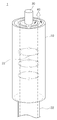
도 1은 본 발명에 따른 말뚝의 단면도이다.
도 2는 도 1에 도시된 말뚝의 일부를 확대하여 도시한 사시도이다.
도 3은 본 발명에 따른 말뚝의 시공상태를 도시한 사시도이다.
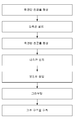
도 4는 본 발명에 따른 말뚝의 시공방법의 예를 나타낸 흐름도이다. 1 is a sectional view of a pile according to the present invention.
FIG. 2 is an enlarged perspective view of a part of the pile shown in FIG. 1. FIG.
3 is a perspective view showing a pile installation state according to the present invention.
4 is a flowchart showing an example of a method of constructing a pile according to the present invention.
이하, 본 발명이 예시적인 도면을 통해 상세하게 설명된다. 각 도면의 구성요소들에 참조부호를 부가함에 있어서, 동일한 구성요소들에 대해서는 비록 다른 도면상에 표시되더라도 가능한 한 동일한 부호를 가지도록 하고 있음에 유의해야 한다. 또한, 본 발명을 설명함에 있어, 관련된 공지 구성 또는 기능에 대한 구체적인 설명이 본 발명의 요지를 흐릴 수 있다고 판단되는 경우에는 그 상세한 설명은 생략한다.BRIEF DESCRIPTION OF THE DRAWINGS FIG. It should be noted that, in adding reference numerals to the constituent elements of the drawings, the same constituent elements are denoted by the same reference symbols as possible even if they are shown in different drawings. In the following description of the present invention, a detailed description of known functions and configurations incorporated herein will be omitted when it may make the subject matter of the present invention rather unclear.
도 1은 본 발명에 따른 말뚝의 단면도이고, 도 2는 도 1에 도시된 말뚝의 일부를 확대하여 도시한 사시도이다. FIG. 1 is a sectional view of a pile according to the present invention, and FIG. 2 is an enlarged perspective view of a part of the pile shown in FIG.
이들 도면에 도시된 바와 같이, 본 발명에 따른 말뚝(1)은, 지반(2)에 형성된 천공홀(3)에 설치되는 외측관(10); 이 외측관 내에 설치되는 내측관(20); 이 내측관 내에 배치되고, 적어도 내측관의 전체 길이에 걸쳐 연장하는 보강재(30); 및 외측관과 내측관 사이 및 내측관과 보강재 사이에 주입되어 경화한 그라우트(40)를 포함하고 있다. As shown in these drawings, the
지반(2)의 천공홀(3)은 예컨대 유압드릴 등과 같은 각종 천공기(미도시)를 이용하여 형성될 수 있다. 이러한 천공홀은 필요에 따라 도 1에 도시된 바와 같이 소정 깊이에서 단차지게 형성될 수 있다. 이때, 확경된 천공홀(3a)에는 외측관(10)이, 상대적으로 축경된 천공홀(3b)에는 내측관(20)이 삽입되어 설치될 수 있다. The
외측관(10)과 내측관(20)은 일정 길이를 가진 중공(中空)의 부재로서, 외측관이 내측관보다 그 길이가 짧은 것이 바람직하지만, 반드시 이에 한정되는 것은 아니다. 외측관과 내측관 사이에 그라우트(40)를 주입하기 위해서, 내측관은 외측관의 내면으로부터 이격되어 설치되게 된다. The
또한, 내측관(20)의 표면에는 내측관의 내부로 가압되어 주입된 그라우트(40)가 외측관(10)을 향하여 유출될 수 있도록 복수의 관통공(22)이 형성될 수 있다. A plurality of through
이들 관통공(22)은 내측관(20)의 길이방향을 따라 1열 또는 복수의 열로 줄지어 형성하여도 좋고, 줄지어 형성하지 않고 내측관의 표면에 2차원적으로 랜덤하게 분포시킴으로써 임의의 적당한 위치에 형성할 수도 있다. These through
이러한 관통공(22)은 미경화된 그라우트(40)를 통과시키는 기능을 수행함과 동시에, 경화한 그라우트(40)와 내측관(20)의 결합력을 강화시키는 기능도 수행할 수 있는 수단이기 때문에, 내측관의 표면상에서 관통공(22)들의 형성 밀도는 필요한 결합력에 따라 조정하여 결정할 수 있다. This through
다만, 복수의 관통공(22)은 내측관(20)의 표면에서 외측관(10)과 대응되는 영역에만 형성되는 것이 바람직하며, 이에 따라 그라우트(40)가 관통공을 통해 내측관과 외측관 사이의 공간으로 주입되게 된다. It is preferable that the plurality of through
보강재(30)는 일정 길이를 가진 중실(中實)의 부재로서, 내측관(20)의 내부에 삽입될 수 있다. 이러한 보강재로는 소정의 직경을 가진 원형 단면의 강재가 바람직하지만, 보강재의 형상과 재질은 반드시 이에 한정되는 것은 아니다. The reinforcing
또한, 보강재(30)는, 도시되어 있지 않지만, 예를 들어 복수의 보강재가 묶음으로 또는 적어도 일부분이 용접 등으로 접합되어 함께 내측관(20) 내에 방사상으로 배열되어, 본 발명의 말뚝(1)에 가해지는 응력을 고루 분산시키도록 하여도 된다. Although not shown, for example, a plurality of stiffeners may be bundled or at least partially welded together and radially arranged in the
또, 보강재(30)는 복수의 보강재를 그 길이방향을 따라 직렬로 정렬시키고 인접한 단부들을 서로 연결하여 구성할 수도 있다. 이러한 경우에, 복수의 보강재의 인접한 단부들 사이에는 커플러(32)가 개재될 수 있는데, 이 커플러는 예를 들어 나사체결 방식으로 각 단부와 결합할 수 있다. The
이와 같이, 복수의 보강재(30)를 커플러(32)에 의해 그 길이방향으로 연결함으로써 내측관(20) 내에 한층 더 보강재를 보충하면서 삽입할 수 있게 되고, 최종적으로는 도 1에 도시되 바와 같이, 보강재가 천공홀의 상단에서부터 지반(2) 안의 천공홀의 하단에 이를 때까지 천공홀(3)의 거의 전체 길이에 걸쳐 위치할 수 있게 되는 것이다. 필요에 따라, 보강재(30)는 내측관으로부터 돌출할 수 있는 길이를 가질 수 있다. As described above, by connecting the plurality of reinforcing
보강재(30) 또는 내측관(20)의 적어도 일부 외주면에는 도시되지 않은 나사산부 또는 방사상으로 연장한 복수의 돌기가 형성될 수 있다. 이로써, 보강재 또는 내측관의 외주면에서 그라우트(40)와 접촉할 수 있는 표면적이 증대되어, 보강재 또는 내측관과 그라우트가 일체로 견고하게 결합할 수 있다.At least a part of the outer circumferential surface of the reinforcing
그라우트(40)로는 시멘트 밀크(cement milk) 또는 모르타르(mortar) 등이 채용될 수 있으나, 반드시 이에 한정되지 않으며, 예컨대 에폭시를 사용한 레진계 그라우트 등과 같은 임의의 그라우트가 사용되어도 무방하다. The
이러한 그라우트(40)는, 지반 위, 즉 지상에 설치되고서 탱크, 펌프, 믹서 등을 포함한 임의의 그라우트 주입장치(미도시)에 의해, 지상으로 개방되어 있는 내측관(20)의 일측 개구를 통하여 주입될 수 있다. 그라우트 주입장치는 이미 널리 알려져 있으므로, 본 명세서에서는 이에 대한 상세한 설명을 생략하기로 한다. The
본 발명의 말뚝(1)은, 도 1에 도시된 바와 같이, 지반(2)에 형성된 천공홀(3)에 주입되어 경화한 그라우트(40)를 포함하여서, 말뚝의 하단 부분이 지반과 연결될 수 있다. 말뚝의 그라우트 안에 보강재(30)가 매설되어 있고, 이 보강재는 말뚝의 길이방향으로 내측관(20)의 전체 길이 내지 말뚝의 거의 전체 길이에 걸쳐 연장하고 있다. The
도 3은 본 발명에 따른 말뚝의 시공상태를 도시한 사시도이다.3 is a perspective view showing a pile installation state according to the present invention.
이에 도시된 바와 같이, 본 발명에 따른 말뚝(1)의 상단에는, 예컨대 철근 콘크리트 등의 기초 구조물(4)에 연결하기 위한 연결판(50)이 설치될 수 있다. 이러한 연결판은 보강재(30)의 상단에 용접되거나, 연결판의 나사구멍에 보강재(30)가 나사체결되거나, 보강재(30)가 연결판의 관통구멍을 관통한 후 보강재에 체결너트(52)가 체결되어 연결판이 체결너트와 외측관 또는 내측관 사이에 고정됨으로써, 보강재와 일체로 연결될 수 있다. As shown in the figure, a connecting
이어서, 연결판(50)과 보강재(30)의 상부가 기초 구조물(4)에 의해 매설될 수 있다.Subsequently, the connecting
본 발명에 따른 말뚝(1)은, 그 상단 부분이 외측관(10)으로 둘러싸여 이 외측관에 의해 보강되어 있다. 외측관은 그 상단 부분이 기초 구조물(26)에 매설되고 그 하단부분은 지반에 매설되는 것이 좋다.The upper part of the
이러한 외측관(10)은 필요한 길이로 제작될 수 있다. 예를 들면, 횡토압력이 발생하는 구간에 대해 말뚝을 탄성 지반에 지지된 보라고 가정하여 이상화시킨 기본 방정식(윙클러(Winkler) 모델)을 바탕으로 하면서 지반 조건을 조사한 결과를 이용하여 말뚝에 가해지는 수평력을 해석할 수 있다. 해당 기본 방정식을 아래 수학식 1에 표시하였다. The
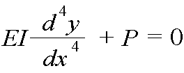
여기서, E는 말뚝의 탄성계수이고, I는 말뚝의 단면2차모멘트로서, EI는 말뚝의 휨 강성(kN·㎡)을 나타낸다. 또, x는 지면으로부터의 깊이(cm), y는 말뚝의 수평변위(cm), P는 수평지반반력(kN/㎡)이다. Where E is the modulus of elasticity of the pile, I is the moment of inertia of the pile, and EI is the flexural stiffness (kN · m2) of the pile. In addition, x is the depth from the ground (cm), y is the horizontal displacement of the pile (cm), and P is the horizontal ground reaction force (kN / m 2).
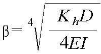
이어서, 수평저항에 관여하는 지면으로부터의 깊이를 산정하는데, 이는 말뚝의 특성치(β)를 결정함으로써 얻을 수 있다. 말뚝의 특성치는 아래 수학식 2에 의해 결정될 수 있다. Subsequently, the depth from the ground associated with the horizontal resistance is calculated, which can be obtained by determining the characteristic value () of the pile. The characteristic value of the pile can be determined by the following equation (2).

여기서, β는 말뚝의 특성치(cm-1)이며, Kh는 수평방향의 지반반력계수(kN/㎥)이고, D는 말뚝의 직경(cm)이다. 마찬가지로, E는 말뚝의 탄성계수이고, I는 말뚝의 단면2차모멘트로서, EI는 말뚝의 휨 강성(kN·㎡)을 나타낸다.Here, β is the characteristic value (cm -1 ) of the pile, K h is the soil reaction force in the horizontal direction (kN / m 3), and D is the diameter of the pile (cm). Similarly, E is the modulus of elasticity of the pile, I is the moment of inertia of the pile, and EI is the flexural stiffness of the pile (kN · m2).
이로써, 말뚝에 가해질 수평방향의 하중에 따라 외측관(10)의 직경을 결정하고, 이 직경을 이용하여 말뚝의 특성치(β)를 구한 다음에 이 특성치의 역수, 즉 1/β로부터 외측관의 바람직한 길이를 산정할 수 있게 되는 것이다. Thus, the diameter of the
본 발명에 따른 말뚝(1)에서는, 내측관(20)의 내부 공간이 경화한 그라우트(40)로 채워져 있으며, 전술한 바와 같이 이 그라우트 안에 보강재(30)가 매설되어 있게 된다. 또한, 그라우트가 복수의 관통공(22)을 통해 외측관(10)을 향해 주입됨으로써, 내측관과 외측관 사이의 공간에도 경화한 그라우트가 채워져 있게 된다. In the
궁극적으로, 본 발명에 따른 말뚝(1)은 지반(2)에 삽입된 보강재(30)와, 수평 저항력을 증대시키기 위한 외측관(10)의 일체화 거동을 통해, 말뚝의 휨 강성을 증대시켜 우수한 수평 저항력을 발휘하게 된다. Ultimately, the
예를 들면, 165mm의 직경을 가진 일반 마이크로파일과, 직경 200mm의 외측관이 설치된 마이크로파일을 서로 비교하는 실증실험의 결과, 외측관이 설치된 마이크로파일의 수평 저항력이 일반 마이크로파일 대비 약 1.6배 증가함을 알 수가 있었다. For example, as a result of an empirical experiment comparing a microfile having a diameter of 165 mm and a microfilm having an outer pipe having a diameter of 200 mm, the horizontal resistance of the microfilm with the outer tube was increased by about 1.6 times .
더불어, 도 1처럼 보강재(30)가 내측관(20)으로부터 지반(2)을 향해 돌출된 경우에는, 내측관으로부터 돌출한 보강재의 외주면에도 그라우트(40)가 밀착해 경화함으로써 보강재와 천공홀(3)의 측벽(즉, 지반) 사이의 공간에도 경화한 그라우트가 채워질 수 있다. 1, the
이에 따라, 본 발명에 따른 말뚝(1)은 기본적으로 갖고 있는 구조적 성능을 발휘할 수 있을 뿐 아니라, 그라우트(40)를 지반에 충진하여 보강재(30)와 지반(2)을 일체로 결합하게 함으로써 지지력을 향상시킬 수 있게 되는 것이다. The
이상과 같이, 본 발명에 따른 말뚝(1)은, 보강재(30) 주위에 주입된 그라우트(40)가 내측관(20) 및 지반(2)에 밀착해 경화함으로써 큰 내력을 가져 상부 하중을 충분히 지지할 수 있음과 동시에, 수평력 및 휨 응력에 대한 저항 성능을 제공할 수 있게 된다. As described above, the
더욱이, 본 발명에 따른 말뚝(1)에서는, 내측관(20)에 형성되어 있는 복수의 관통공(22)을 통해 내측관(20)과 외측관(10) 사이의 공간에 그라우트가 충전되어 있기 때문에, 보강재(30)와 외측관(10)의 견고한 일체화 거동을 가능하게 하고 휨 강성을 증대시킴과 더불어, 상부의 단면적을 확장시켜 말뚝의 수평 변위에 대한 안정성을 향상시킬 수 있다. Further, in the
이에 따라, 본 발명에 따른 말뚝에 의하면, 말뚝의 설치 수량을 줄일 수 있어, 공사 기간의 단축과 시공 비용의 감소 및 환경 부하의 경감을 달성할 수 있는 효과를 얻게 되는 것이다.
Thus, according to the pile of the present invention, it is possible to reduce the installation amount of the pile, thereby reducing the construction period, the construction cost, and the environmental load.
도 4는 본 발명에 따른 말뚝의 시공방법의 예를 나타낸 흐름도이다. 4 is a flowchart showing an example of a method of constructing a pile according to the present invention.
본 발명에 따른 말뚝(1)의 시공방법은, 지반(2)에 천공홀(3)을 형성하는 단계; 천공홀(3)에 외측관(10)을 설치하는 단계; 외측관 내에 내측관(20)을 설치하는 단계; 내측관 내에 보강재(30)를 삽입하는 단계; 및 보강재가 매립되도록 내측관 내에 그라우트(40)를 주입하고 경화시키는 단계를 포함하고 있다. A method of constructing a pile (1) according to the present invention comprises the steps of: forming a perforation hole (3) in a ground (2); Installing an outer tube (10) in the perforation hole (3); Installing an inner tube (20) in the outer tube; Inserting a stiffener (30) in the inner tube; And injecting and curing the
우선, 예컨대 유압드릴 등과 같은 각종 천공기를 이용하여 지반(2)을 굴착하면서 천공홀(3)을 형성한다. 이러한 천공홀에 외측관(10)을 설치하고, 이어서 외측관 내에 내측관(20)을 설치할 수 있다. First, the
특히, 도 1에 도시된 바와 같이 내측관(20)보다 그 길이가 짧은 외측관(10)이 적용되는 경우에는 소정 깊이에서 천공홀(3)은 단차지게 형성될 수 있다. In particular, when the
이와 같이 단차진 천공홀(3)에서, 낮은 깊이 및 확경된 천공홀(3a)에는 외측관(10)이 삽입되어 설치될 수 있고, 지면으로부터 더 깊고 상대적으로 축경된 천공홀(3b)에는 내측관(20)이 삽입되어 설치될 수 있다.In the stepped
혹은, 도 4에 도시된 바와 같이, 낮은 깊이의 확경된 천공홀(3a)을 먼저 굴착하고 나서 이 확경된 천공홀에 외측관(10)을 설치한 다음, 확경된 천공홀의 바닥으로부터 상대적으로 축경된 천공홀(3b)을 굴착한 후 이 축경된 천공홀에 내측관(20)을 설치하여도 된다. Alternatively, as shown in FIG. 4, after the drilled
이렇게 하여 본 발명에 따른 말뚝(1)의 상단 부분에 설치되는 외측관(10)은 말뚝의 상단 부분을 둘러싸면서 말뚝의 상단 부분을 보강하게 되며, 이러한 외측관에 의해 말뚝의 수평 저항력이 증대될 수 있게 되는 것이다. Thus, the
외측관(10)의 길이는 전술한 바와 같이 말뚝의 특성치(β)로부터 결정될 수 있는데, 여기서 말뚝의 특성치는 위 수학식 2에 의해 구해질 수 있고, 이로부터 외측관의 길이는 특성치의 역수(1/β)로 산정될 수 있다. The length of the
천공홀(3)에 내측관(20)의 설치가 완료되면, 이 내측관 내에 보강재(30)를 삽입한다. 이 보강재는 복수의 보강재를 그 길이방향을 따라 직결로 정렬시키고 인접한 단부들을 서로 연결하여 구성할 수 있다. 이러한 경우에, 복수의 보강재의 인접한 단부들 사이에는 커플러(32)가 개재될 수 있다. When the installation of the
이와 같이, 복수의 보강재(30)를 커플러(32)에 의해 그 길이방향으로 연결함으로써 내측관(20) 내에 한층 더 보강재를 보충하면서 삽입할 수 있게 되고, 최종적으로는 도 1에 도시되 바와 같이, 보강재가 천공홀의 상단에서부터 지반(2) 안의 천공홀의 하단에 이를 때까지 천공홀(3)의 거의 전체 길이에 걸쳐 위치할 수 있다. As described above, by connecting the plurality of reinforcing
다음으로, 지상에 설치된 그라우트 주입장치에 의해, 지상으로 개방된 내측관(20)의 일측 개구를 통하여 그라우트(40)를 주입함으로써, 내측관의 내부 공간과, 내측관과 외측관(10) 사이의 공간에 그라우트를 충전한다. Next, the
특히, 도 1에 도시된 바와 같이 내측관(20)으로부터 돌출한 보강재(30)가 적용되는 경우에는, 돌출한 보강재와 천공홀(3)의 측벽 사이의 공간에도 그라우트(40)를 충전한다. In particular, when the
이러한 그라우트(40)의 주입과 동시에, 내측관(20)의 관통공(22)을 통해 그라우트를 통과시켜 외측관(10)을 향해 유출시키고, 유출한 그라우트가 내측관의 안팎으로 밀착되어 경화함으로써 경화한 그라우트와 내측관의 결합력을 강화시키게 된다. At the same time as the injection of the
그 후, 주입한 그라우트(40)가 경화하는 것을 대기하고, 그라우트의 경화가 완료됨으로써, 내부에는 보강재(30)가 매설되고, 상단 부분에는 외측관(10)에 의해 확장된 단면적을 가지며, 하단 부분에서는 보강재와 그라우트 및 지반의 결합부를 갖게 되는 본 발명의 말뚝(1)이 완성되게 되는 것이다. Thereafter, the injected
다음으로, 도 3 및 도 4에 도시된 것처럼, 본 발명에 따른 말뚝(1)의 상단에 연결판(50)을 설치한다. 이에 의해 예컨대 철근 콘크리트 등의 기초 구조물(4)에 연결될 수 있다. 이후에, 외측관(10)의 주위에 토사의 되메우기를 수행하여, 외측관의 하부를 지반에 매설하는 한편, 연결판(50) 전체와 외측관 및 보강재(30)의 상부가 기초 구조물에 의해 매설될 수 있게 기초 구초물을 구축한다. 이로써, 구조물과 지반을 연결하는 말뚝이 완성되게 된다.Next, as shown in Figs. 3 and 4, a connecting
이와 같이 시공된 본 발명의 말뚝(1)은, 기존의 말뚝이 가지고 있는 구조적 성능은 그대로 이용하면서, 내측관(20) 및 외측관(10)의 내부로 주입되는 그라우트(40)에 의해 보강재(30)와 내측관 및 외측관의 견고한 일체화 거동을 가능케 하고 상부의 단면적을 확장시켜 수평 저항력을 대폭 증대시킬 수 있게 된다. The
이에 따라, 본 발명에 따른 말뚝에 의하면, 말뚝의 설치 수량을 줄일 수 있어, 공사 기간의 단축과 시공 비용의 감소 및 환경 부하의 경감을 달성할 수 있는 효과를 얻게 되는 것이다. Thus, according to the pile of the present invention, it is possible to reduce the installation amount of the pile, thereby reducing the construction period, the construction cost, and the environmental load.
이상의 설명은 본 발명의 기술 사상을 예시적으로 설명한 것에 불과한 것으로서, 본 발명이 속하는 기술 분야에서 통상의 지식을 가진 자라면 본 발명의 본질적인 특성에서 벗어나지 않는 범위에서 다양한 수정 및 변형이 가능할 것이다. 따라서, 본 발명에 개시된 실시예는 본 발명의 기술 사상을 한정하기 위한 것이 아니라 설명하기 위한 것이고, 이러한 실시예에 의하여 본 발명의 기술 사상의 범위가 한정되는 것은 아니다. 본 발명의 보호 범위는 아래의 청구범위에 의하여 해석되어야 하며, 그와 동등한 범위 내에 있는 모든 기술 사상은 본 발명의 권리범위에 포함되는 것으로 해석되어야 할 것이다.
The foregoing description is merely illustrative of the technical idea of the present invention, and various changes and modifications may be made by those skilled in the art without departing from the essential characteristics of the present invention. Therefore, the embodiments disclosed in the present invention are intended to illustrate rather than limit the scope of the present invention, and the scope of the technical idea of the present invention is not limited by these embodiments. The scope of protection of the present invention should be construed according to the following claims, and all technical ideas within the scope of equivalents should be construed as falling within the scope of the present invention.
1: 말뚝
2: 지반
3: 천공홀
4; 기초 구조물
10: 외측관
20: 내측관
30: 보강재
40: 그라우트
50: 연결판1: pile 2: ground
3:
10: outer tube 20: inner tube
30: stiffener 40: grout
50: connection plate
Claims (15)
상기 외측관 내에 설치되는 내측관;
상기 내측관 내에 배치되고, 적어도 상기 내측관의 전체 길이에 걸쳐 연장하는 보강재; 및
상기 외측관과 상기 내측관 사이 및 상기 내측관과 상기 보강재 사이에 주입되어 경화한 그라우트
를 포함하는 말뚝.An outer tube installed in the perforation hole formed in the ground;
An inner tube installed in the outer tube;
A stiffener disposed within the inner tube and extending at least over the entire length of the inner tube; And
The grout being injected between the outer tube and the inner tube and between the inner tube and the reinforcing material,
Including a pile.
상기 외측관은 상기 내측관보다 길이가 짧은 것을 특징으로 하는 말뚝.The method according to claim 1,
Wherein the outer tube is shorter than the inner tube.
상기 외측관의 길이는, 상기 외측관의 직경을 결정하고 상기 직경을 이용하여 말뚝의 특성치(β)를 구한 다음에 상기 특성치의 역수로 산정되며,
상기 특성치는
The length of the outer pipe is determined by determining the diameter of the outer pipe, calculating the characteristic value of the pile using the diameter, and then calculating the inverse of the characteristic value,
The characteristic value
상기 내측관은 상기 외측관의 내면으로부터 이격되어 설치된 것을 특징으로 하는 말뚝. The method according to claim 1,
Wherein the inner tube is spaced from the inner surface of the outer tube.
상기 내측관의 표면에는 상기 내측관의 내부로 주입된 상기 그라우트가 상기 외측관을 향하여 유출될 수 있도록 복수의 관통공이 형성된 것을 특징으로 하는 말뚝. 5. The method of claim 4,
Wherein a plurality of through holes are formed on a surface of the inner tube so that the grout injected into the inner tube can flow out toward the outer tube.
상기 보강재는 일정 길이를 가진 중실(中實)의 부재인 것을 특징으로 하는 말뚝.The method according to claim 1,
Wherein the stiffener is a solid member having a predetermined length.
복수의 보강재가 길이방향을 따라 직렬로 정렬되고, 상기 보강재의 인접한 단부들이 서로 연결된 것을 특징으로 하는 말뚝. The method according to claim 6,
Wherein a plurality of stiffeners are aligned in series along the longitudinal direction and adjacent ends of the stiffener are connected to each other.
상기 복수의 보강재의 인접한 단부들 사이에는 커플러가 개재된 것을 특징으로 하는 말뚝.8. The method of claim 7,
And a coupler is interposed between adjacent ends of the plurality of stiffeners.
상기 보강재는 상기 내측관으로부터 지반을 향해 돌출되고,
상기 내측관으로부터 돌출한 상기 보강재와 상기 천공홀의 측벽 사이의 공간에도 상기 그라우트가 채워진 것을 특징으로 하는 말뚝. The method according to claim 6,
The reinforcing member is projected from the inner tube toward the ground,
And the grout is filled in a space between the reinforcement projecting from the inner tube and the side wall of the perforation hole.
상기 보강재 또는 상기 내측관의 적어도 일부 외주면에는 나사산부 또는 방사상으로 연장한 복수의 돌기가 형성된 것을 특징으로 하는 말뚝. The method according to claim 1,
Wherein at least a part of the outer surface of the stiffener or the inner tube is provided with a threaded portion or a plurality of radially extending protrusions.
상기 말뚝의 상단에는 기초 구조물에 연결하기 위한 연결판이 설치되고,
상기 연결판은 상기 보강재와 연결되는 것을 특징으로 하는 말뚝. The method according to claim 1,
A connecting plate for connecting to the foundation structure is installed at the upper end of the pile,
Wherein the connecting plate is connected to the stiffener.
상기 천공홀에 외측관을 설치하는 단계;
상기 외측관 내에 내측관을 설치하는 단계;
상기 내측관 내에 보강재를 삽입하는 단계; 및
상기 보강재가 매립되도록 상기 내측관 내에 그라우트를 주입하고 경화시키는 단계
를 포함하는 말뚝의 시공방법. Forming a perforation hole in the ground;
Providing an outer tube in the perforation hole;
Installing an inner tube in the outer tube;
Inserting a stiffener in the inner tube; And
Injecting grout into the inner tube so that the reinforcing material is embedded and curing
The method comprising the steps of:
상기 천공홀은 소정 깊이에서 단차지게 형성되는 것을 특징으로 하는 말뚝의 시공방법.13. The method of claim 12,
Wherein the perforation holes are stepped at a predetermined depth.
상기 확경된 천공홀에 외측관을 설치하는 단계;
상기 확경된 천공홀의 바닥으로부터 상대적으로 축경된 천공홀을 형성하는 단계;
상기 축경된 천공홀에 내측관을 설치하는 단계;
상기 내측관 내에 보강재를 삽입하는 단계; 및
상기 보강재가 매립되도록 상기 내측관 내에 그라우트를 주입하고 경화시키는 단계
를 포함하는 말뚝의 시공방법. Forming a drilled hole in the ground;
Providing an outer tube in the perforated hole;
Forming a relatively reduced diameter perforation hole from the bottom of the enlarged perforation hole;
Providing an inner tube in the reduced diameter perforation hole;
Inserting a stiffener in the inner tube; And
Injecting grout into the inner tube so that the reinforcing material is embedded and curing
The method comprising the steps of:
상기 그라우트의 경화가 완료되면, 말뚝의 상단에 연결판을 설치하고, 상기 연결판이 기초 구조물에 의해 매설될 수 있게 기초 구초물을 구축하는 단계를 더 포함하는 것을 특징으로 하는 말뚝의 시공방법.
15. The method according to claim 12 or 14,
Further comprising the step of installing a connecting plate at the upper end of the pile when the curing of the grout is completed, and constructing a foundation so that the connecting plate can be buried by the foundation structure.
Priority Applications (2)
| Application Number | Priority Date | Filing Date | Title |
|---|---|---|---|
| KR1020170067536A KR20180131042A (en) | 2017-05-31 | 2017-05-31 | Pile and method for constucting same |
| PCT/KR2017/006844 WO2018221781A1 (en) | 2017-05-31 | 2017-06-28 | Pile and construction method therefor |
Applications Claiming Priority (1)
| Application Number | Priority Date | Filing Date | Title |
|---|---|---|---|
| KR1020170067536A KR20180131042A (en) | 2017-05-31 | 2017-05-31 | Pile and method for constucting same |
Publications (1)
| Publication Number | Publication Date |
|---|---|
| KR20180131042A true KR20180131042A (en) | 2018-12-10 |
Family
ID=64455973
Family Applications (1)
| Application Number | Title | Priority Date | Filing Date |
|---|---|---|---|
| KR1020170067536A KR20180131042A (en) | 2017-05-31 | 2017-05-31 | Pile and method for constucting same |
Country Status (2)
| Country | Link |
|---|---|
| KR (1) | KR20180131042A (en) |
| WO (1) | WO2018221781A1 (en) |
Cited By (2)
| Publication number | Priority date | Publication date | Assignee | Title |
|---|---|---|---|---|
| KR102053231B1 (en) * | 2019-05-28 | 2019-12-06 | 대한기초엔지니어링(주) | Foundation reinforcing method using existing pile |
| KR102394061B1 (en) * | 2021-09-28 | 2022-05-04 | 주식회사 에스와이텍 | Earth proof phc hybrid pile using small diameter steel pipe and construction method for the same |
Family Cites Families (5)
| Publication number | Priority date | Publication date | Assignee | Title |
|---|---|---|---|---|
| KR100779988B1 (en) * | 2006-05-11 | 2007-11-27 | 주식회사 쏘일텍 | Method for constructing micropile |
| KR100871882B1 (en) * | 2007-01-30 | 2008-12-05 | 김수현 | Pile construction method by multi section segment pile |
| KR100843577B1 (en) * | 2007-02-23 | 2008-07-03 | 김원철 | Pile construction method by casing |
| JP5109531B2 (en) * | 2007-08-20 | 2012-12-26 | Jfeスチール株式会社 | Double pipe type pile head structure |
| KR101635529B1 (en) * | 2015-11-17 | 2016-07-04 | 이강수 | Composite pile construction method |
-
2017
- 2017-05-31 KR KR1020170067536A patent/KR20180131042A/en active Search and Examination
- 2017-06-28 WO PCT/KR2017/006844 patent/WO2018221781A1/en active Application Filing
Cited By (2)
| Publication number | Priority date | Publication date | Assignee | Title |
|---|---|---|---|---|
| KR102053231B1 (en) * | 2019-05-28 | 2019-12-06 | 대한기초엔지니어링(주) | Foundation reinforcing method using existing pile |
| KR102394061B1 (en) * | 2021-09-28 | 2022-05-04 | 주식회사 에스와이텍 | Earth proof phc hybrid pile using small diameter steel pipe and construction method for the same |
Also Published As
| Publication number | Publication date |
|---|---|
| WO2018221781A1 (en) | 2018-12-06 |
Similar Documents
| Publication | Publication Date | Title |
|---|---|---|
| JP4599384B2 (en) | Embankment structure and construction method thereof | |
| JP5274145B2 (en) | Cast-in-place pile and its construction method | |
| KR20060092552A (en) | The non-strut down framework construction method of having used cast in place concrete pile | |
| US20100319280A1 (en) | Precast Temporary Facility Structure and a Construction Method for the Same | |
| JP5113342B2 (en) | Embankment structure | |
| JP2007277880A (en) | Fill structure and its construction method | |
| JP2008231799A (en) | Base isolation structure | |
| JP2009007745A (en) | Axial-force transmission structure for permanent sub-substructural column and foundation pile, and construction method for permanent sub-substructural column | |
| KR100956879B1 (en) | Stress dispersion type microfile | |
| KR101863792B1 (en) | Pre-loading method of reinforcing pile | |
| KR101065017B1 (en) | A shoring method using arch plate pile and H-Pile | |
| JP2016108881A (en) | Reinforcement structure and reinforcement method for stone masonry retaining wall | |
| US11359344B2 (en) | Barbed micropiles for soil reinforcement | |
| KR20180131042A (en) | Pile and method for constucting same | |
| KR100654964B1 (en) | Reinforcing Member of Pile with an Extended Head | |
| KR101864857B1 (en) | Construction method of foundation pile with reinforced casing structure | |
| KR102018140B1 (en) | A micro-pile and the method | |
| KR100984040B1 (en) | Method of reinforced earth retaining wall for cutting face through double reinforcing execution | |
| JP2000120080A (en) | Hollow cylindrical body and its construction method | |
| KR101553865B1 (en) | Composite phc pile with concrete filling plate and structure therewith | |
| JP2019218795A (en) | Joint structure of foundation pile and foundation slab | |
| KR200427561Y1 (en) | Multiful prestressed concrete file | |
| KR20190143420A (en) | Reinforcement Structure of PHC Pile, PHC Pile having such Reinforcement Structure, and Constructing Method for such PHC Pile | |
| KR102400508B1 (en) | Construction method of retaining wall installation structure | |
| KR101732133B1 (en) | Reinforcement structure for pile and construction method of reinforcement structure for pile using the same |
Legal Events
| Date | Code | Title | Description |
|---|---|---|---|
| A201 | Request for examination | ||
| E902 | Notification of reason for refusal | ||
| AMND | Amendment | ||
| E601 | Decision to refuse application | ||
| X091 | Application refused [patent] | ||
| AMND | Amendment | ||
| E90F | Notification of reason for final refusal | ||
| AMND | Amendment |