JP2008212721A - Game machine - Google Patents
Game machine Download PDFInfo
- Publication number
- JP2008212721A JP2008212721A JP2008153194A JP2008153194A JP2008212721A JP 2008212721 A JP2008212721 A JP 2008212721A JP 2008153194 A JP2008153194 A JP 2008153194A JP 2008153194 A JP2008153194 A JP 2008153194A JP 2008212721 A JP2008212721 A JP 2008212721A
- Authority
- JP
- Japan
- Prior art keywords
- display
- variable display
- state
- big hit
- display control
- Prior art date
- Legal status (The legal status is an assumption and is not a legal conclusion. Google has not performed a legal analysis and makes no representation as to the accuracy of the status listed.)
- Withdrawn
Links
Images


Abstract
Description
本発明は、パチンコ遊技機やコイン遊技機あるいはスロットマシーン等で代表される遊技機に関する。詳しくは、所定の始動条件の成立に基づいて各々が識別可能な複数種類の識別情報の可変表示を行なうことが可能な可変表示装置を備え、該可変表示装置の表示結果が予め定められた特定の表示結果となったときに遊技者にとって有利な特定遊技状態に制御可能となる遊技機に関する。 The present invention relates to a gaming machine represented by a pachinko gaming machine, a coin gaming machine, a slot machine or the like. Specifically, a variable display device capable of variably displaying a plurality of types of identification information, each of which can be identified based on the establishment of a predetermined start condition, and a display result of the variable display device is specified in advance. The present invention relates to a gaming machine that can be controlled to a specific gaming state that is advantageous to the player when the display result is obtained.
この種の遊技機として従来から一般的に知られているものに、たとえば、可変表示開始条件が成立したときに可変表示を行なうことが可能な可変表示装置を備え、該可変表示装置の表示結果が予め定められた特定の表示結果となったときに遊技者にとって有利な特定遊技状態に制御可能となる遊技機があった。 What is conventionally known as this type of gaming machine includes, for example, a variable display device capable of performing variable display when a variable display start condition is satisfied, and the display result of the variable display device There is a gaming machine that can be controlled to a specific gaming state that is advantageous to the player when a predetermined display result is obtained.
従来の遊技機の中には、種々の数字,文字,図柄等の表示記号を変動可能に表示する液晶ディスプレイ型の可変表示部を有する表示装置が配設され、表示装置には可動部材が備えられており、可変表示部の表示態様と対応させて可動部材を動作させて大当りかはずれを判定できるようにするものがある(たとえば、特許文献1参照。)。
このように従来の遊技機としては、遊技機の表示装置に可動部材を備え、可動部材が可変表示部の表示態様と対応して動作し、遊技の興趣を高めるように構成されたものがあった。しかしながら、この種の従来の遊技機は、可変表示装置において演出を行なうものであり、保留データ表示部を利用して演出を行なうものではないため、演出を行なう場所に新しさがなく、遊技者の興奮を今一歩盛り上げることができにくいという欠点があった。 As described above, some conventional gaming machines include a movable member provided in the display device of the gaming machine, and the movable member operates in accordance with the display mode of the variable display unit, thereby enhancing the interest of the game. It was. However, since this type of conventional gaming machine produces an effect on the variable display device and does not produce an effect using the hold data display unit, the place where the production is performed is not new, and the player There was a drawback that it was difficult to excite the excitement.
本発明は、係る事情に鑑み考え出されたものであり、その目的は、保留データ数表示部を利用して演出を行なうことで、興趣を向上させることのできる遊技機を提供することである。 The present invention has been conceived in view of such circumstances, and an object of the present invention is to provide a gaming machine that can improve the interest by performing effects using the reserved data number display section. .
(1) 所定の始動条件(始動入賞)の成立に基づいて各々が識別可能な複数種類の識別情報(特別図柄)の可変表示を行なうことが可能な可変表示装置(可変表示装置8)を備え、該可変表示装置の表示結果が予め定められた特定の表示結果(たとえば「333」等のゾロ目)となったときに遊技者にとって有利な特定遊技状態(大当り状態)に制御可能となる遊技機(パチンコ遊技機1)であって、
可変表示開始条件の成立に基づいて前記可変表示装置の表示結果を前記特定の表示結果とするか否かを決定する表示結果決定手段(遊技制御用マイクロコンピュータ53、図15のS56,S57)と、
前記可変表示装置において前記複数種類の識別情報の可変表示を開始させた後、前記表示結果決定手段に従う表示結果を導出表示させる可変表示制御を行なう可変表示制御手段(表示制御用マイクロコンピュータ800、図29、図30、図31)と、
前記始動条件が成立しても直ちに可変表示を開始できないときに前記可変表示開始条件の成立に基づいて可変表示を開始できるまで前記始動条件の成立を保留データとして記憶する保留記憶手段(RAM55、図14のS43)と、
該保留記憶手段により記憶されている保留データ数に対応する数だけ所定の表示態様(図8の「緑色点灯」)の保留表示を行なうことによって、前記保留データ数を報知する保留データ数表示部(始動記憶表示器18)と、
前記保留データ数表示部の保留表示を遮蔽するための遮蔽部材(恐竜の顔の形をした遮蔽部材21a、恐竜の下顎の形をした遮蔽部材21b)と、
該遮蔽部材を制御して前記保留データ数表示部の保留表示が遮蔽された遮蔽状態と遮蔽されていない非遮蔽状態とに変化させる遮蔽部材制御手段(表示制御用マイクロコンピュータ800、遮蔽状態は図4の(A−4)を参照、非遮蔽状態は図4の(A−1)〜(A−3)および(A−5)を参照)と、
前記保留記憶手段に記憶されている保留データのうちに前記可変表示装置の表示結果が前記特定の表示結果となる保留データが存在するときに、当該保留データに対応する保留表示を前記所定の表示態様とは異なる特別表示態様(図8の「青色点滅1」、「青色点滅2」、「青色点灯」、「赤色点灯」)にするか否かを決定する特別表示態様決定手段(遊技制御用マイクロコンピュータ53、図16のS81,S84,S85)と、
該特別表示態様決定手段の決定に従い、前記可変表示装置の表示結果が前記特定の表示結果となる保留データに対応する保留表示を前記特別表示態様にする特別表示制御を実行することにより、前記可変表示装置の表示結果が前記特定の表示結果となることを予告する予告手段(表示制御用マイクロコンピュータ800、図4参照)とを含み、
前記保留データ数表示部が前記遮蔽状態であるときに前記特別表示制御を開始し(図5参照)、
前記遮蔽部材制御手段は、前記予告手段が前記特別表示制御を開始した後、前記保留データ数表示部の保留表示を前記遮蔽状態から前記非遮蔽状態に変化させる制御を行なう(図4の(A−4)から(A−5)に変化させる)。
(1) A variable display device (variable display device 8) capable of variably displaying a plurality of types of identification information (special symbols) each identifiable on the basis of establishment of a predetermined start condition (start prize) A game that can be controlled to a specific game state (big hit state) advantageous to the player when the display result of the variable display device becomes a predetermined specific display result (for example, a doublet such as “333”). Machine (Pachinko machine 1),
Display result determination means (
After the variable display of the plurality of types of identification information is started in the variable display device, variable display control means (
When the variable display cannot be started immediately even if the start condition is satisfied, a hold storage means (
A hold data number display section for informing the number of hold data by performing hold display in a predetermined display mode ("green light" in FIG. 8) corresponding to the number of hold data stored in the hold storage means. (Starting memory display 18);
Shielding members (
Shielding member control means for controlling the shielding member to change the holding display of the holding data number display section between a shielded state and a non-shielded non-shielded state (
When there is pending data in which the display result of the variable display device becomes the specific display result among the pending data stored in the pending storage means, a pending display corresponding to the pending data is displayed in the predetermined display. Special display mode determining means (for game control) for determining whether or not to make a special display mode ("blue flashing 1", "blue flashing 2", "blue lighting", "red lighting") in FIG. 8) different from the
In accordance with the determination by the special display mode determining means, the variable display device performs the special display control to change the hold display corresponding to the hold data whose display result is the specific display result to the special display mode. Notice means (
The special display control is started when the reserved data number display unit is in the shielding state (see FIG. 5),
The shield member control means performs control to change the hold display of the hold data number display section from the shield state to the non-shield state after the notice means starts the special display control ((A in FIG. 4). -4) to (A-5)).
このような構成によれば、保留データ数表示部において特定の表示結果の発生を予告するという演出が行なわれるため、可変表示を中断することなく予告を行なうことができる。また、保留データ数表示部が遮蔽状態であるときから前記表示部を前記特別表示態様にする制御を開始するため、遮蔽部材が保留データ表示部を遮蔽したときは、特定の表示結果の発生に対する遊技者の期待感を高めることができる。また、遮蔽部材が稼動して保留データ数表示部を遮蔽状態にするため、遊技者の注意を遮蔽部材と保留データ数表示部とに向けることができる。 According to such a configuration, an effect of notifying the occurrence of a specific display result in the reserved data number display section is performed, so that the notification can be performed without interrupting the variable display. Moreover, in order to start the control which makes the said display part the said special display mode from when the reservation data number display part is a shielding state, when a shielding member shields the reservation data display part, with respect to generation | occurrence | production of a specific display result The expectation of the player can be increased. In addition, since the shielding member operates and puts the reserved data number display portion in the shielding state, the player's attention can be directed to the shielding member and the reserved data number display portion.
(2) 前記遮蔽部材制御手段は、前記可変表示においてリーチ状態(リーチ状態、リーチ態様、リーチ表示態様)が成立したとき、前記遮蔽部材(恐竜の下顎の形をした遮蔽部材21b)を制御して前記保留データ数表示部(始動記憶表示器18)を前記遮蔽状態(図4の(A−4))にする制御を行なう。
(2) The shielding member control means controls the shielding member (the
このような構成によれば、リーチ状態の発生に対する期待感だけではなく、保留データ数表示部において特定の表示結果となることを予告するという演出に対しても遊技者に興味を抱かせることができる。 According to such a configuration, the player can be interested not only in the expectation for the occurrence of the reach state, but also in the effect of notifying that a specific display result is obtained in the reserved data count display unit. it can.
(3) 前記遮蔽部材制御手段は、前記可変表示装置において前記複数種類の識別情報(特別図柄)が可変開始されたとき、前記遮蔽部材(恐竜の下顎の形をした遮蔽部材21b)を制御して前記保留データ数表示部(始動記憶表示器18)を前記遮蔽状態にする。
(3) The shielding member control means controls the shielding member (the
このような構成によれば、可変表示装置において複数種類の識別情報が可変開始される毎に保留データ数表示部において特定の表示結果となることを予告するという演出が行なわれるため、予告の発生頻度が高くなり、遊技者の期待感を向上させることができる。 According to such a configuration, every time a plurality of types of identification information are variably started in the variable display device, an effect is given in which a specific display result is notified in the reserved data number display unit, and thus a notice is generated. The frequency increases and the player's expectation can be improved.
(4) 前記保留記憶手段に記憶されている保留データのうち前記可変表示装置の表示結果が前記特定の表示結果とならない保留データに対応する保留表示を前記特別表示態様にするか否かを決定する偽特別表示態様決定手段(遊技制御用マイクロコンピュータ53、図16のS82,S83,S84,S85)と、
該偽特別表示態様決定手段の決定に従い、前記可変表示装置の表示結果が前記特定の表示結果とならない保留データに対応する保留表示を前記特別表示態様にする特別表示制御を実行することにより、前記可変表示装置の表示結果が前記特定の表示結果となることを予告する偽予告手段(表示制御用マイクロコンピュータ800、図4の(A−5))とを含み、
該偽予告手段は、前記保留データ数表示部(始動記憶表示器18)が前記遮蔽状態であるときに前記特別表示制御を開始し(図5参照)、
前記遮蔽部材制御手段は、前記偽予告手段が前記特別表示制御を開始した後、前記保留データ数表示部の保留表示を前記遮蔽状態から前記非遮蔽状態に変化させる制御を行なう(図4の(A−4)から(A−5)に変化させる)。
(4) Determining whether or not to put the hold display corresponding to the hold data in which the display result of the variable display device does not become the specific display result among the hold data stored in the hold storage means to the special display mode. False special display mode determination means (
In accordance with the determination of the false special display mode determination means, by executing special display control that sets the hold display corresponding to the hold data whose display result of the variable display device does not become the specific display result to the special display mode, Including false notice means (
The false notice means starts the special display control when the reserved data number display unit (starting storage display 18) is in the shielding state (see FIG. 5),
The shield member control means performs control to change the hold display of the hold data number display section from the shield state to the non-shield state after the false notice means starts the special display control ((FIG. 4 ( A-4) is changed to (A-5)).
このような構成によれば、保留記憶手段に記憶されている保留データのうちに前記可変表示装置の表示結果が前記特定の表示結果とならない保留データが存在するときに、保留データ数表示部において特定の表示結果の発生を予告するという演出が行なわれるため、予告の発生頻度が高くなり、遊技者の期待感を向上させることができる。 According to such a configuration, when there is pending data in which the display result of the variable display device does not become the specific display result among the pending data stored in the pending storage unit, the pending data number display unit Since the effect of notifying the occurrence of a specific display result is performed, the occurrence frequency of the notice is increased, and the player's expectation can be improved.
(5) 前記表示結果決定手段により前記特定の表示結果を発生させないことが決定されたとき、リーチ状態を成立させるか否かを決定するリーチ状態決定手段(遊技制御用マイクロコンピュータ53、図16のS74,S75)をさらに含み、
前記偽特別表示態様決定手段は、前記リーチ状態決定手段によりリーチ状態を成立させることが決定されたとき(図16のS76)に、前記保留記憶手段に記憶されている保留データのうちのいずれかに対応する保留表示を前記特別表示態様にするか否かを決定する(図16のS82,S84,S85)。
(5) Reach state determination means (
The false special display mode determination means is one of the hold data stored in the hold storage means when it is determined that the reach state is established by the reach state determination means (S76 in FIG. 16). It is determined whether or not the hold display corresponding to is set to the special display mode (S82, S84, S85 in FIG. 16).
このような構成によれば、リーチ状態決定手段によりリーチ状態を成立させることが決定されたときに、保留データ数表示部において特定の表示結果の発生を予告するという演出が行なわれるため、予告の発生頻度が高くなり、遊技者の期待感を向上させることができる。 According to such a configuration, when it is determined by the reach state determination means that the reach state is established, the reserved data number display unit performs an effect of notifying the occurrence of a specific display result. The frequency of occurrence increases, and the player's expectation can be improved.
(6) 前記特別表示態様決定手段が前記保留表示を前記特別表示態様にすることを決定したときに該特別表示態様を予め定められた複数種類の中(図8の「青色点滅1」、「青色点滅2」、「青色点灯」、「赤色点灯」)から選択する特別表示態様選択手段(遊技制御用マイクロコンピュータ53、図16のS87,S88)をさらに含み、
該特別表示態様選択手段は、前記特別表示態様の種類によって前記予告の信頼度が異なるように、前記特別表示態様を選択する(図10参照)。
(6) When the special display mode determining means determines that the hold display is set to the special display mode, the special display mode is selected from a plurality of predetermined types ("blue flashing 1", " Further including special display mode selection means (
The special display mode selection means selects the special display mode so that the reliability of the notice varies depending on the type of the special display mode (see FIG. 10).
このような構成によれば、信頼度の高い特別表示態様によって予告が行われたときは、遊技者は特定の表示結果の発生に対して期待感を抱くことができる。 According to such a configuration, when a notice is given in a special display mode with high reliability, the player can have a sense of expectation for the occurrence of a specific display result.
(7) 前記特別表示態様決定手段は、前記保留記憶手段に記憶されている保留データ数が2つ以上であるとき(図16のS62)、前記決定をする。 (7) The special display mode determination means makes the determination when the number of reserved data stored in the reserved storage means is two or more (S62 in FIG. 16).
このような構成によれば、保留データ記憶手段に保留データが記憶されていないときに保留データ数表示部において特定の表示結果の発生を予告するという演出が行なわれることを防止することができる。 According to such a configuration, it is possible to prevent an effect of giving a notice of occurrence of a specific display result in the hold data number display unit when the hold data is not stored in the hold data storage unit.
次に、本発明の実施の形態を図面に基づいて詳細に説明する。なお、この実施の形態においては、遊技機の一例としてパチンコ遊技機を示すが、本発明はこれに限らず、コイン遊技機あるいはスロットマシン等であってもよく、所定の始動条件の成立に基づいて各々が識別可能な複数種類の識別情報の可変表示を行なうことが可能な可変表示装置を備え、該可変表示装置の表示結果が予め定められた特定の表示結果となったときに遊技者にとって有利な特定遊技状態に制御可能となる遊技機であれば、すべて対象となる。 Next, embodiments of the present invention will be described in detail with reference to the drawings. In this embodiment, a pachinko gaming machine is shown as an example of a gaming machine. However, the present invention is not limited to this, and may be a coin gaming machine or a slot machine, based on the establishment of a predetermined starting condition. A variable display device capable of variably displaying a plurality of types of identification information, each of which can be identified, when the display result of the variable display device is a predetermined display result. Any gaming machine that can be controlled to an advantageous specific gaming state is a target.
まず、遊技機の一例であるパチンコ遊技機の全体の構成について説明する。
図1は、本発明に係る遊技機の一例のパチンコ遊技機1およびこれに対応して設置されたカードユニット50の正面図である。
First, the overall configuration of a pachinko gaming machine that is an example of a gaming machine will be described.
FIG. 1 is a front view of a
カードユニット50には、カード利用可表示ランプ151が設けられており、カードユニット50が使用可能な状態にある旨が、このカード利用可表示ランプ151の点灯または点滅により遊技者に知らされる。このカードユニット50は、遊技機設置島に設置されている複数台のパチンコ遊技機1の間に挿入された状態で設置されており、左右どちらの遊技機に接続されているかが連結台方向表示器153により表示される。
The card unit 50 is provided with a card
遊技者がカード残高の記録されたプリペイドカードをカード挿入口155に挿入すると、そのプリペイドカードに記録されているカード残高が読取られる。次に、遊技者が所定の貸玉操作を行なうことにより、予め入力設定されている貸出単位額分の残高が減額されるとともに、その貸出単位額分の打玉がパチンコ遊技機1の打玉供給皿3に貸出される。
When the player inserts a prepaid card in which the card balance is recorded into the
カードユニット50には、端数表示スイッチ152が設けられている。この端数表示スイッチ152を押圧操作することにより、たとえばカード残高やエラーが発生したときのエラーコードなどの情報がパチンコ遊技機1に設けられた情報表示器(図示省略)に表示される。図中156はカードユニット錠であり、このカードユニット錠156に所定のキーを挿入して解錠操作することにより、カードユニット50の前面側を開成できるように構成されている。
The card unit 50 is provided with a
パチンコ遊技機1は、額縁状に形成されたガラス扉枠2を有する。このガラス扉枠2の後方には、遊技盤6が着脱自在に取付けられている。また、ガラス扉枠2の下部表面には打玉供給皿3がある。打玉供給皿3の下部には、打玉供給皿3から溢れた玉を貯留する余剰玉受皿4と、遊技者が打球操作するための操作ノブ5とが設けられている。
The
操作ノブ5を遊技者が操作することにより、打玉供給皿3内に貯留されている打玉を1個ずつ発射することができる。発射された打玉は、誘導レール29によって遊技領域7内に導かれる。誘導レール29から遊技領域7への出口部分には、弁状の逆流防止部材30が設けられている。この逆流防止部材30によって一旦遊技領域7内に打込まれた打玉が誘導レール29に逆戻りすることが防止される。
By operating the
遊技領域7の中央には、各々が識別可能な複数種類の識別情報の一例となる特別図柄を可変表示(以下、変動表示ともいう)させる可変表示装置8が設けられている。なお、識別情報とは、所定の始動条件の成立に基づいて各々が識別可能な複数種類の識別情報のことである。
In the center of the
この可変表示装置8には、液晶表示器よりなる特別図柄表示部9、始動記憶表示器18、通過記憶表示器15、遮蔽部材21aおよび遮蔽部材21bが設けられている。また、可変表示装置8の左側方部および右側方部にワープ入口11、可変表示装置8の下方には、始動口(始動入賞口)14が構成された始動用電動役物14aと、開閉板20の傾動により打玉の入賞可能な開成状態となる可変入賞球装置19とが設けられている。また、一般入賞口として、可変表示装置8の下方左右に入賞口24がそれぞれ設けられている。また、打玉が進入可能な通過口12が可変表示装置8の下方左右に設けられている。ワープ入口11に進入した打玉は、可変表示装置8の裏面側を通って下方に流下してステージ(ワープ出口)13から再度遊技領域7に放出される。このため、ステージ13から放出された打玉は、始動口14に比較的入賞しやすい状態となる。また、26は、打込まれた打玉がいずれの入賞口24や可変入賞球装置19にも入賞しなかったときにアウト玉として回収するアウト口であり、25は、装飾ランプである。
The
遊技領域7の外周には遊技効果LED42と、賞球の払出し時に点灯する賞球ランプ43と、球切れ中に点灯するランプ球切れランプ44とが設けられており、遊技領域7の上部の左右にはステレオ音の音声などの効果音を発生するためのスピーカ41,41が設けられている。
On the outer periphery of the
なお、特別図柄表示部9は、液晶表示器に限らず、CRT(Cathode Ray Tube)、FED(Field Emission Display)、PDP(Plasma Display Panel)、ドットマトリクス等その他の画像表示式の表示装置により構成されてもよい。
The special
通過口12に進入した打玉は、ゲートスイッチ12a(図2参照)で検出される。打玉がゲートスイッチ12aで検出されると、通過記憶表示器15に表示されている記憶数が上限に達していなければ、所定の乱数値が抽出される。そして、普通図柄表示器10の可変表示を開始させることができる状態であれば、普通図柄表示器10の可変表示が開始される。なお、普通図柄表示器10が可変表示している最中にさらに打玉が通過口に進入し、ゲートスイッチ12aで検出されたときには、普通図柄表示器10の可変表示を開始させることができない状態であるので、「4」を記憶数の上限として通過玉(乱数値等)が所定の記憶装置に記憶され、その記憶数が通過記憶表示器13においてLEDの点灯数により表示される。そして、普通図柄表示器10の可変表示が開始される毎に、点灯しているLEDの数を1つ減らす。
The hit ball that has entered the passage 12 is detected by the gate switch 12a (see FIG. 2). When a hit ball is detected by the gate switch 12a, a predetermined random number value is extracted if the number of memories displayed on the
普通図柄表示器10には、「〇」が付されている当り普通図柄表示器と、「×」が付されているはずれ普通図柄表示器とがある。通過口12に打玉が進入したときに抽出された乱数値が所定の当り決定値と一致するときは、普通図柄表示器10における可変表示の表示結果が当りであると判断され、「〇」が付されている当り普通図柄表示器が点灯する。一方、抽出された乱数値が所定の当り決定値と一致しないときは、普通図柄表示器10における可変表示の表示結果がはずれであると判断され、「×」が付されているはずれ普通図柄表示器が点灯する。当りとなり「〇」が付されている当り普通図柄表示器が点灯した場合には、始動用電動役物14aに設けられた左右1対の可動片が1回開成する。これにより始動用電動役物14aが開成状態となって打玉がより始動入賞しやすくなる。始動用電動役物14aが開成状態にあるときに打玉が1つ始動入賞すれば、可動片が元の位置まで閉成して打玉が始動入賞しにくい閉成状態に戻る。また、始動用電動役物14aが開成状態となってから所定の開放期間が経過すれば、始動入賞が発生しなくとも可動片が元の位置まで閉成して開成状態は終了する。
The
始動口14に入賞(始動入賞という)した始動入賞玉は、遊技盤6に設けられた始動口スイッチ17(図2参照)により検出される。始動入賞玉が始動口スイッチ17で検出されると5個の賞球が払出されるとともに、始動記憶表示器18に表示されている記憶数が上限に達していなければ、所定の乱数値が抽出される。
A start winning ball that has won the start opening 14 (referred to as a start winning) is detected by a start opening switch 17 (see FIG. 2) provided on the
特別図柄表示部9の可変表示を開始させることができる状態(可変表示開始条件の成立)であれば、特別図柄表示部9において特別図柄の可変表示を開始させる。なお、特別図柄表示部9が可変表示している最中にさらに打玉が始動口14に入賞し、始動口スイッチ17で検出されたときは、特別図柄表示部9の可変表示を開始させることができない状態であるので、「4」を記憶数の上限として始動入賞玉(乱数値等)が後述する遊技制御用マイクロコンピュータ53に搭載されたRAM55に記憶されて、その記憶数が始動記憶表示器18においてLEDを所定の表示態様(緑色)で点灯することにより表示される。そして、可変表示装置が可変開始される毎に、点灯しているLEDの数を1つ減らす。
If the special
可変表示装置8の特別図柄表示部9には、左可変表示部、中可変表示部および右可変表示部の3つの可変表示部が設けられている。各可変表示部の可変表示を開始させることができる状態となると、3つの可変表示部において特別図柄の可変表示が一斉に開始される。可変表示(更新表示、変動表示ともいう)は、各可変表示部において上から下へ特別図柄をスクロールさせることによって行なわれる。この実施の形態では、各可変表示部において可変表示される特別図柄は、0〜9の10種類の数字である。なお、特別図柄表示部9において可変表示される特別図柄は、数字、文字、図形、模様、キャラクタ等の識別情報であれば、どのような識別情報であってもよく、数字のみ、文字のみ、図形のみ、模様のみ、キャラクタのみ、または、これらを適宜組合せたもの等であってもよい。
The special
所定時間の経過後、可変表示が左可変表示部、右可変表示部、中可変表示部の順番に停止表示される。すべての可変表示部において可変表示が停止表示されたとき、3つの可変表示部において予め定められた特定の表示結果(たとえば「333」等のゾロ目)が揃うと「大当り」となり、遊技状態が遊技者にとって有利な特定遊技状態(大当り状態ともいう)に移行する。以下、このような特定遊技状態(大当り状態)となる特定の表示結果を大当り図柄という。特定遊技状態では、可変入賞球装置19の開閉板20が開成して大入賞口が開口する。これにより、打玉を大入賞口に入賞させることが可能な遊技者にとって有利な第1の状態に制御される。開閉板20はソレノイド21によって駆動される。
After a predetermined time has elapsed, the variable display is stopped and displayed in the order of the left variable display portion, the right variable display portion, and the middle variable display portion. When the variable display is stopped and displayed in all the variable display sections, if the predetermined display results (for example, “333” or the like) in the three variable display sections are aligned, it becomes “big hit” and the gaming state becomes A transition is made to a specific gaming state (also referred to as a big hit state) that is advantageous to the player. Hereinafter, a specific display result in such a specific gaming state (big hit state) is referred to as a big hit symbol. In the specific game state, the opening /
可変入賞球装置19の大入賞口内部には、可変入賞球装置19に入賞した打玉を検出するカウントスイッチ27が設けられている。また、大入賞口内は、特定入賞領域と通常入賞領域とに区分されており、特定入賞領域には、V入賞を検出するVカウントスイッチ28が設けられている。特定入賞領域に入賞した入賞玉はVカウントスイッチ28により検出された後、カウントスイッチ27により検出される。一方、通常入賞領域に入賞した通常入賞玉は大入賞口内においてはカウントスイッチ27のみにより検出される。可変入賞球装置19に入賞した入賞玉がカウントスイッチ27により検出される毎に15個の賞球が払出される。
A
パチンコ遊技機1の背面側には、各入賞口および可変入賞球装置に入賞した入賞玉を所定の入賞経路に沿って導く入賞玉集合カバー(図示省略)が設けられており、この入賞玉集合カバーにより導かれた入賞玉は、入賞玉を1個宛処理する入賞玉処理装置(図示省略)に供給される。入賞玉処理装置には入賞球検出スイッチ(図示省略)が設けられており、これにより、入賞玉処理装置による景品玉の払出しの対象となる入賞玉が検出される。
On the back side of the
可変入賞球装置19の第1の状態は、大入賞口に進入した打玉の数が所定個数(たとえば10個)に達したとき、または所定期間(たとえば30秒間)経過したときのうちのいずれか早い方の条件が成立したときに一旦終了して開閉板20が閉成する。これにより、可変入賞球装置19は、打玉を入賞させることが不可能な遊技者にとって不利な第2の状態に制御される。そして、可変入賞球装置19が第1の状態となっている期間中に進入した打玉が特定入賞領域に特定入賞し、Vカウントスイッチ28により検出されたことを条件として、その回における可変入賞球装置19の第1の状態が終了して第2の状態となった後、再度開閉板20が開成されて、可変入賞球装置19を第1の状態にする繰返し継続制御が実行される。この繰返し継続制御の実行上限回数は、たとえば16回と定められている。繰返し継続制御において、可変入賞球装置19が第1の状態にされている状態はラウンドと呼ばれる。繰返し継続制御の実行上限回数が16回のときには、第1ラウンドから第16ラウンドまでの16ラウンド分、可変入賞球装置19が第1の状態にされ得る。
The first state of the variable winning ball apparatus 19 is either when the number of hit balls that have entered the special winning opening reaches a predetermined number (for example, 10) or when a predetermined period (for example, 30 seconds) has elapsed. When the earlier condition is established, the process is temporarily terminated and the opening /
3つの可変表示部の表示結果が予め定められた確変大当り図柄(たとえば、「777」等のゾロ目)により構成されるものである場合には、通常遊技状態に比べて大当りが発生する確率が向上された確率変動状態となる。以下、確変図柄による大当りを確変大当りという。また、確変図柄以外の大当り図柄を非確変図柄といい、非確変図柄による大当りを非確変大当りという。 If the display results of the three variable display portions are configured with predetermined probability variation jackpot symbols (for example, a doublet such as “777”), there is a probability that a jackpot will occur compared to the normal gaming state. Improved probability variation state. In the following, jackpots with probability variation symbols are referred to as probability variation jackpots. A jackpot symbol other than the probability variation symbol is called a non-probability variation symbol, and a jackpot due to the non-probability variation symbol is called a non-probability variation jackpot.
確変大当りが発生すると、所定の継続期間だけ、確率変動状態に制御される。また、この期間内に、再度確変大当りが発生した場合には、2回目の確変大当りに伴う特定遊技状態の終了後に、再び確率変動状態となる。したがって、確変大当りが連続する回数を制限しない場合には、極めて長時間に亘って確率変動状態に繰返し制御される場合があり、特別遊技状態により遊技者の射幸心を煽り過ぎてしまうことになる。そこで、このパチンコ遊技機1の場合には、初回の確変大当りが発生した後、所定回、確変大当りが連続すると、確変大当りが発生しないように制限がかけられる。また、確率変動状態は、高確率状態、確率向上状態、または確変状態とも呼ばれる。確率変動状態においては、さらに、後述する普通図柄表示器10の表示結果が当りとなる確率も向上させられる。
When a probable big hit occurs, the probability variation state is controlled for a predetermined duration. In addition, when the probability variation jackpot occurs again within this period, the probability variation state again occurs after the end of the specific gaming state associated with the second probability variation jackpot. Therefore, if the number of consecutive probable big hits is not limited, it may be repeatedly controlled to the probability fluctuation state for an extremely long time, and the player's gambling will be overwhelmed by the special gaming state. . Therefore, in the case of this
3つの可変表示部の表示結果が大当り図柄でも、確変大当り図柄でもない場合は、「はずれ」となり、遊技状態は変化せずに通常状態のままとなる。 When the display results of the three variable display portions are neither big hit symbol nor probable big hit symbol, the game state is “disconnected” and the gaming state remains unchanged and remains in the normal state.
また、各可変表示部の可変表示中においては、リーチ状態(リーチ態様、リーチ表示態様)が発生する場合がある。 Further, a reach state (reach mode, reach display mode) may occur during variable display of each variable display unit.
ここで、リーチ状態(リーチ表示態様)とは、所定の始動条件の成立に基づいて各々が識別可能な複数種類の識別情報が可変表示される可変表示部を備えた可変表示装置を有し、可変表示部において前記複数種類の識別情報を可変開始させた後、時期を異ならせて複数の表示結果を導出表示し、予め定められた特定の表示結果となったときに、遊技状態が遊技者にとって有利な特定遊技状態となる遊技機において、複数の表示結果の一部がまだ導出表示されていない段階で、既に導出表示されている表示結果が特定の表示結果となる条件を満たしている表示状態をいう。 Here, the reach state (reach display mode) has a variable display device including a variable display unit that variably displays a plurality of types of identification information that can each be identified based on establishment of a predetermined start condition, After variably starting the plurality of types of identification information in the variable display section, a plurality of display results are derived and displayed at different times, and the gaming state is determined to be a player when a predetermined display result is obtained. In a gaming machine that is in a specific gaming state that is advantageous for the player, a display that satisfies the condition that the display result that has already been derived and displayed becomes a specific display result when some of the plurality of display results have not yet been derived and displayed State.
また、別の表現をすれば、リーチ状態とは、表示状態が変化可能な可変表示部を複数有する可変表示装置における識別情報の表示結果が予め定められた特定の表示結果となった場合に、遊技状態が遊技者にとって有利な特定遊技状態となる遊技機において、前記可変表示装置の表示結果がまだ導出表示されていない段階で、前記特定の表示結果が表示されやすい可変表示態様となったと遊技者に思わせるための表示状態をいう。そして、たとえば、前記特定の表示結果となった状態を維持しながら複数の前記可変表示部による可変表示を行なう状態もリーチ表示状態に含まれる。さらにリーチの中には、それが出現すると、通常のリーチ状態に比べて、大当りが発生しやすいものがある。このような特定のリーチ状態をスーパーリーチという。 In other words, the reach state is when the display result of the identification information in the variable display device having a plurality of variable display units that can change the display state becomes a predetermined specific display result. In a gaming machine in which the gaming state is in a specific gaming state advantageous for the player, the game is performed when the specific display result is easily displayed when the display result of the variable display device is not yet derived and displayed. This is the display state that makes a person think. For example, a state in which variable display by the plurality of variable display units is performed while maintaining the state in which the specific display result is obtained is also included in the reach display state. Furthermore, some reach is likely to generate a big hit when it appears, compared to the normal reach state. Such a specific reach state is called super reach.
また、リーチ状態とは、可変表示装置が可変開始された後可変表示制御が進行して表示結果が導出表示される前段階にまで達した時点でも、前記特定の表示結果となる表示条件から外れていない表示態様をもいう。 The reach state is also deviated from the display condition for the specific display result even when the variable display control is started after the variable display device is variably started and the display result is reached before the display result is derived and displayed. It also refers to a display mode that is not.
また、リーチ状態とは、可変表示装置の可変表示制御が進行して表示結果が導出表示される前段階にまで達した時点での表示状態であって、前記表示結果が導出表示される以前に決定されている複数の可変表示部の表示結果の少なくとも一部が前記特定の表示結果となる条件を満たしている場合の表示状態をもいう。 The reach state is a display state at the time when the variable display control of the variable display device progresses to reach a stage before the display result is derived and displayed, and before the display result is derived and displayed. It also refers to a display state in a case where at least a part of the determined display results of the plurality of variable display units satisfies the condition for the specific display result.
また、リーチ状態とは、複数の可変表示部における一部の可変表示部において表示結果がまだ導出表示されていない段階で、既に導出表示されている可変表示部の表示結果が特定の表示結果となる条件を満たしている表示状態をもいう。 In addition, the reach state means that the display result of the variable display unit already derived and displayed is a specific display result when the display result is not yet derived and displayed in some of the variable display units of the plurality of variable display units. A display state that satisfies the following conditions.
また、全回転リーチ状態とは、複数の可変表示部のすべてで特定の表示結果を保持した状態で可変表示を行なっている表示状態をいう。 The full rotation reach state refers to a display state in which variable display is performed while a specific display result is held in all of the plurality of variable display units.
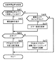
始動記憶表示器18の上側には、恐竜の顔の形をした遮蔽部材21aが設けられており、始動記憶表示器18の下側には、恐竜の下顎の形をした遮蔽部材21bが設けられている。遮蔽部材21bは、遊技盤6の裏面に設けられるソレノイド21c(図2参照)によって上下方向に稼動する。ソレノイド21cの働きによって下顎である遮蔽部材21bが上方向に稼動し、恐竜の口が閉じられたとき、始動記憶表示器18は遊技者からは見えない遮蔽状態となる。一方、下顎である遮蔽部材21bが下方向に稼動し、恐竜の口が開いているとき、始動記憶表示器18は遊技者から見える非遮蔽状態となる。そして、可変表示中にリーチ状態が発生した場合、この遮蔽部材21a、21bを利用した予告演出が行われる。可変表示中にリーチ状態が発生した場合、遮蔽部材21bが上方向に稼動し、始動記憶表示器18が遊技者からは見えない遮蔽状態となる。遮蔽状態となった遮蔽部材21bは、所定時間の経過後に下方向に稼動し、恐竜の口が開かれた非遮蔽状態となる。遮蔽状態となってから非遮蔽状態となるまでの間に始動記憶表示器18のLEDが所定の表示態様(たとえば、LEDを緑色に点灯)とは異なる特別表示態様(たとえば、LEDを赤色に点灯)で点灯される。そして、遊技者は、恐竜の口が開かれ、非遮蔽状態となったときに始動記憶表示器18のLEDが特別表示態様で表示されていることを確認することができる。
A
図2は、遊技制御基板131における回路構成の一例を示すブロック図である。
図2には、遊技制御基板131、払出制御基板137、音制御基板170、ランプ制御基板135、発射制御基板91および表示制御基板80が示されている。払出制御基板137、音制御基板170、ランプ制御基板135、発射制御基板91および表示制御基板80には、マイクロコンピュータ等が搭載されており、たとえば、CPUやI/Oポートが設けられている。
FIG. 2 is a block diagram illustrating an example of a circuit configuration in the
FIG. 2 shows a
遊技制御基板131には、プログラムにしたがってパチンコ遊技機1を制御する遊技制御用マイクロコンピュータ53と、スイッチ回路58と、ソレノイド回路59と、情報出力回路64と、初期リセット回路65と、アドレスデコード回路67とが搭載されている。
The
遊技制御用マイクロコンピュータ53は、ゲーム制御用のプログラム等を記憶するROM54、ワークメモリとして使用される記憶手段の一例であるRAM55、制御用プログラムにしたがって制御動作を行なうCPU56およびI/Oポート部57を含む遊技制御用のマイクロコンピュータである。この実施の形態ではROM54,RAM55はCPU56に搭載されている。すなわち、CPU56は、1チップマイクロコンピュータである。なお、CPU56とROM54、RAM55とは1チップ化されていなくてもよい。つまり、ROM54、RAM55およびI/Oポート部57は外付けであっても内蔵されていてもよい。また、I/Oポート部57は、マイクロコンピュータにおける情報入出力可能な端子である。
The
スイッチ回路58は、ゲートスイッチ12a、始動口スイッチ17、カウントスイッチ27、Vカウントスイッチ28、満タンスイッチ148、入賞口スイッチ24a、球切れ検出スイッチ167、球切れスイッチ187および賞球カウントスイッチ301Aからの信号を遊技制御用マイクロコンピュータに与えるための回路である。
The
ソレノイド回路59は、始動用電動役物14aを開閉するソレノイド16および特別可変入賞球装置19の開閉板を開閉するソレノイド26を遊技制御用マイクロコンピュータ53からの指令にしたがって駆動させる回路である。
The
情報出力回路64は、遊技制御用マイクロコンピュータ53から与えられるデータにしたがって、確率変動が生じて確率変動状態となっていることを示す確変情報、大当りが発生し特定遊技状態となっていることを示す大当り情報および始動入賞のうち特別図柄表示部9の可変表示に有効に使用される始動入賞の発生を示す始動入賞情報をホール管理コンピュータ等のホストコンピュータに対して出力する回路である。
The
アドレスデコード回路67は、遊技制御用マイクロコンピュータ53から与えられるアドレス信号をデコードしてI/Oポート57のうちのいずれかのポートを選択するための信号を出力する回路である。
The
払出制御基板137には、球払出装置97およびカードユニット45が接続される。音制御基板170にはスピーカ41が接続される。ランプ制御基板135には、遊技効果LED42、賞球ランプ43、球切れランプ44、通過記憶表示器15および装飾ランプ25が接続される。発射制御基板91には、操作ノブ(打玉操作ハンドル)5と打玉ハンマー(図示省略)を駆動する駆動モータ94とが接続される。駆動モータ94の駆動力は、操作ノブ5の操作量にしたがって調整される。表示制御基板80には、普通図柄表示器10、特別図柄表示部9、始動記憶表示器18およびソレイノイド21cが接続される。
A
遊技制御用マイクロコンピュータ53から払出制御基板137に搭載されたマイクロコンピュータへは、賞球の払出制御に関する指令情報としてのコマンドと、貸玉の払出制御に関する指令情報としてのコマンド(たとえば、玉貸し禁止コマンド、玉貸し禁止解除コマンド等)とが送信される。
From the
遊技制御用マイクロコンピュータ53から音制御基板170に搭載されたマイクロコンピュータへは、音制御基板170に搭載されたマイクロコンピュータによりスピーカ41から出力される効果音等の音声の制御に関する指令情報としての音制御コマンド等の情報が送信される。
From the
遊技制御用マイクロコンピュータ53からランプ制御基板135に搭載されたランプ制御用マイクロコンピュータへは、ランプ制御基板135により制御が行なわれる機器の制御のための指令情報であるランプ制御コマンド等の情報が送信される。ランプ制御基板135に搭載されているランプ制御手段であるランプ制御用マイクロコンピュータ(図示省略)が、遊技効果LED42、賞球ランプ43、球切れランプ44、装飾ランプ25、通過記憶表示器15および始動記憶表示器20の表示制御を行なう。ランプ制御基板135では、ランプ制御用マイクロコンピュータが、ランプ制御コマンドに応じて制御対象機器を駆動する制御を行なう。
Information such as a lamp control command, which is command information for controlling devices controlled by the
特別図柄を可変表示する特別図柄表示部9および普通図柄を可変表示する普通図柄表示器10の表示制御は、表示制御基板80に搭載されている可変表示制御手段である表示制御用マイクロコンピュータ800によって行なわれる。遊技制御用マイクロコンピュータ53から表示制御用マイクロコンピュータ800へは、特別図柄表示部9の表示制御に関する指令情報としての表示制御コマンド等の情報が送信される。また、遮蔽部材21b動作用のソレノイド21cが接続されており、ソレノイド駆動信号がソレノイド21cに供給される。
The display control of the special
図3は、表示制御基板80内の回路構成を、画像表示を実現するLCD(特別図柄表示部)9とともに示すブロック図である。
FIG. 3 is a block diagram showing a circuit configuration in the
RAM101aを内蔵する表示制御用CPU101は、制御データROM102に格納されたプログラムに従って動作し、遊技制御基板31から入力バッファ回路105における入力バッファ105aを介してストローブ信号としての表示制御信号INT(割込信号ともいう)が入力されると表示制御用CPU101が割込動作状態となって表示制御用のコマンドデータを取込む。そして、取込んだ表示制御コマンドデータに従って、LCD(特別図柄表示部)9に表示される画像の表示制御を行なう。制御データROM102には、変動表示の表示パターンに関するデータ等の表示制御用のデータが各種記憶されている。
The
具体的には、表示制御用CPU101は、表示コマンドデータと図柄変動データの初期画面の識別番号を制御データROM102から読出し、VDP103に送信する。VDP103は、表示画面の識別番号に応じて、表示画面における画像の配置関係を示すマップデータをVRAM87に記憶させる。VRAM87に記憶されたマップデータには、制御データROM102に格納された図柄制御用プログラムに従い、図柄の拡大、縮小、回転、反転、座標等の情報が付加される。VDP103は、所定のタイミングでVRAM87からマップデータを読み出し、マップデータに含まれる各画像の識別番号に基づいて、キャラクタROM86から各画像のドットデータを読み出す。次に、VDP103は、読み出したドットデータに着色処理を行ない画像表示信号を生成する。そして、VDP103は、生成した画像信号をD−A変換回路104で変換したアナログのRGB信号と、複合同期信号SYNCをLCD(特別図柄表示部)9に送信する。LCD(特別図柄表示部)9は、送信されてきたRGB信号と複合同期信号SYNCに基づいてLCD(特別図柄表示部)9に画像を表示する。
Specifically, the
なお、図3には、VDP103をリセットするためのリセット回路83、VDP103に動作クロックを与えるための発振回路85、使用頻度の高い画像データを格納するキャラクタROM86、および表示制御コマンドデータを入力する入力バッファ回路105も示されている。キャラクタROM86に格納される使用頻度の高い画像データとは、たとえば、LCD9に表示される人物、動物または文字、図形もしくは記号等からなる画像などである。
FIG. 3 shows a
表示制御用CPU101は、表示制御コマンドデータを記憶しておくためのRAM101aを内蔵しており、遊技制御基板31から表示制御コマンドを受信すると、各変動パターンにおいて予め決められている背景やキャラクタを画面上で移動表示する制御を行なう。なお、予め決められているタイミングで背景やキャラクタの切換も行なわれるが、それらも表示制御用CPU101が独自に制御する。
The
また、表示制御基板80側において表示制御コマンドが入力される入力バッファ回路105は、遊技制御基板31から表示制御基板80へ向かう方向にのみ信号の伝送を許容するが表示制御基板80側から遊技制御基板131側へ向かう信号の伝送を行なわない不可逆性入力手段である。入力バッファ回路105を構成する入力バッファ105aとして、たとえば、汎用のCMOS−ICである74HC244が2チップ用いられる。この入力バッファ105aのイネーブル端子には常にローレベル(GNDレベル)が与えられている。このような構成によれば、表示制御基板80から遊技制御基板31に信号が与えられる可能性を確実になくすことができる。従って、表示制御基板80側から遊技制御基板131側に信号が伝わる余地はなく、表示制御コマンドの伝送経路に不正改造が加えられても、不正改造によって出力される信号が遊技制御基板131側に伝わることはない。このため、遊技制御基板131と表示制御基板80との間の信号の一方向通信が担保され、表示制御コマンドの伝送経路を介して遊技制御基板31に不正な信号(データ)を入力させて不正な制御動作を行なわせる不正行為を確実に防ぐことができる。また、不可逆性入力手段は、バッファIC回路で構成されているために、比較的容易に遊技制御基板131への不正情報の入力を阻止できる。なお、不可逆性入力手段として、個別のトランジスタ等の他の回路素子を設けてもよい。
The
また、遊技制御基板131側において表示制御コマンドが出力される出力バッファ回路63も同様に、遊技制御基板131から表示制御基板80へ向かう方向にのみ信号の伝送を許容するが表示制御基板80側から遊技制御基板31側へ向かう信号の伝送を行なわない不可逆性を有する出力インタフェースである。従って、表示制御基板80側から遊技制御基板31側に信号が伝わる余地はなく、表示制御コマンドの伝送経路に不正改造が加えられても、不正改造によって出力される信号が遊技制御基板131側に伝わることはない。
Similarly, the
図4は、遮蔽部材21a、21bを利用して行なわれる予告演出の様子を示した画面図である。
FIG. 4 is a screen diagram showing a state of a notice effect performed using the
前述したように始動記憶表示器18の上下には、恐竜の顔の形をした遮蔽部材21aと恐竜の下顎の形をした遮蔽部材21bとが設けられている。図中の下向きの矢印は可変表示部において特別図柄が可変表示されていることを示している。可変表示中にリーチ状態が発生した場合、この遮蔽部材21aおよび遮蔽部材21bを利用して予告演出が行われる。予告演出の様子を画面図に沿って説明する。
As described above, the
最初、恐竜の下顎の形をした遮蔽部材21bは、恐竜の口が開かれた状態であり、始動記憶表示器18を遊技者が見ることができる非遮蔽状態となっている。始動記憶表示器18のLEDが所定の表示態様(緑色点灯)で4つ点灯しており、始動記憶が4つあることを示している。このとき、特別図柄表示部9の可変表示は停止した状態となっている(A−1)。しばらくすると、始動記憶に基づいて特別図柄表示部9の可変表示部において可変表示が開始される。始動記憶に基づいて可変表示が開始されたので、4つ点灯していた始動記憶表示器18のLEDが1つ消灯する(A−2)。所定時間の経過後、まず、左可変表示部の特別図柄が停止表示される。次に、右可変表示部の特別図柄が停止表示される。このとき、左可変表示部の特別図柄と右可変表示部の特別図柄とが同じ特別図柄で停止表示され、リーチ状態が発生する(A−3)。リーチ状態が発生すると、恐竜の下顎の形をした遮蔽部材21bがソレイノイド21cによって上方向に稼動され、恐竜の口が閉じられた状態となり、始動記憶表示器18を遊技者が見ることができない遮蔽状態となる(A−4)。所定時間の経過後、恐竜の口が開き、始動記憶表示器18を遊技者が見ることができる非遮蔽状態となる。このとき、3つの始動記憶のうちに表示結果が大当りとなる始動記憶が含まれている場合、大当りとなる始動記憶に該当する始動記憶表示器18のLEDが所定の表示態様とは異なる特別表示態様(「青色点滅1」、「青色点滅2」、「青色点灯」、「赤色点灯」)で表示されることにより、大当りの発生が予告報知される。最後に中可変表示部の特別図柄が停止表示され、すべての可変表示部の特別図柄が停止表示される(A−5)。
Initially, the shielding
以上に説明した予告演出には、ガセの予告演出が行なわれる場合もある。つまり、始動記憶のうちに大当りとなるものが記憶されていない場合であっても、始動記憶表示器18のLEDが所定の表示態様から特別表示態様に変化することがある。ガセの予告演出については後で詳しく述べることとする。
The notice effect described above may be a notice effect of gasses. That is, even if the big hit is not stored in the start memory, the LED of the
図5は、始動記憶表示器18のLEDが所定の表示態様から特別表示態様に切替わるタイミングを説明するための図である。
FIG. 5 is a diagram for explaining the timing when the LEDs of the
図5は各可変表示部の可変表示が開始されてからすべての可変表示部が停止表示されるまでの様子を示しており、その間における可変表示の様子、遮蔽部材21bの様子、始動記憶表示器18の様子を示したものである。
FIG. 5 shows the state from the start of variable display of each variable display unit to the stop display of all variable display units. The state of variable display, the state of the shielding
特別図柄表示部9の可変表示が開始(変動開始)されたとき、恐竜の下顎の形をした遮蔽部材21bは非遮蔽状態であり、始動記憶表示器18のLEDは、所定の表示態様で表示されている。可変表示中にリーチ状態が発生すると、遮蔽部材21bが上方向に稼動し、恐竜の口が閉じた遮蔽状態となる。このとき始動記憶表示器18は、遮蔽部材21bにより覆い隠され、遊技者からは見ることができない状態となっている。所定時間が経過すると、遮蔽部材21bが下方向に稼動し、恐竜の口が開いた非遮蔽状態となり、遊技者が始動記憶表示器18を見ることができる状態となる。恐竜の口が開いた非遮蔽状態となったとき、始動記憶表示器18は、所定の表示態様から特別表示態様に切替わっており、予告表示中となっている。始動記憶表示器18のLEDは恐竜の口が閉じて遮蔽状態となってから恐竜の口が開いて非遮蔽状態となるまでの間に所定の表示態様から特別表示態様に切替わる。そのタイミングとしては、恐竜の口が閉じた遮蔽状態から恐竜の口が開いた非遮蔽状態までの間であればいつでもよい。
When variable display of the special
以上に説明した始動記憶表示器18のLEDが所定の表示態様から特別表示態様に切替わるタイミングは、ガセの予告演出が行なわれるときも同様である。
The timing at which the LEDs of the start-up
このように、始動記憶表示器18において大当りの発生を予告するという演出が行なわれるため、可変表示を中断することなく予告演出を行なうことができる。また、始動記憶表示器18が遮蔽状態であるときから表示部を特別表示態様にする制御を開始するため、遮蔽部材21bが始動記憶表示器18を遮蔽したときは、大当りの発生に対する遊技者の期待感を高めることができる。また、遮蔽部材21bが稼動して始動記憶表示器18を遮蔽状態にするため、遊技者の注意を遮蔽部材21bと始動記憶表示器18とに向けることができる。
Thus, since the effect of notifying the occurrence of the big hit is performed on the start-up
また、リーチ状態が発生したときに、遮蔽部材21a、21bを利用して予告演出を行なうことにより、リーチ状態の発生に対する期待感だけでなく、始動記憶表示器18において行われる予告演出に対しても遊技者に興味を抱かせることができる。
In addition, when a reach state occurs, a notice effect is performed using the
また、確変大当りや大当りが表示結果として表示されるときに発生するリーチ状態の場合だけでなく、はずれが表示結果として表示されるときに発生するリーチ状態の場合にも予告演出が行われるので、予告の発生頻度が高くなり、遊技者の期待感を向上させることができる。 In addition, not only in the case of the reach state that occurs when the probability variation big hit or big hit is displayed as the display result, but also in the case of the reach state that occurs when the outage is displayed as the display result, The occurrence frequency of the notice is increased, and the player's expectation can be improved.
図6は、パチンコ遊技機1の遊技制御に用いられる乱数を生成するための各ランダムカウンタを示す図である。
FIG. 6 is a diagram showing each random counter for generating a random number used for game control of the
この実施の形態においては、複数種類の乱数の生成に複数種類のランダムカウンタが用いられている。このランダムカウンタは、遊技制御用プログラムが定期的に実行される毎(具体的には2msec毎)、または遊技制御用プログラムが定期的に実行される毎および割込処理の余り時間にその値が「1」ずつ加算更新される。 In this embodiment, a plurality of types of random counters are used to generate a plurality of types of random numbers. This random counter has a value every time the game control program is executed periodically (specifically, every 2 msec), or every time the game control program is executed periodically and at the remaining time of the interrupt process. "1" is added and updated.
R1は、特定遊技状態としての大当りを発生させるか否かをランダムに決定するものであり、「0」〜「199」の範囲内で、2msec毎に「1」ずつ加算更新され、その上限である「199」まで達すると再度「0」から加算更新されるものである。始動口スイッチ17により始動入賞が検出されると、それに応じてこのランダムカウンタのカウント値が抽出され、その抽出されたカウント値が予め定められた大当り決定値と一致するか否かが表示結果が導出表示される前に判定される。抽出されたカウント値と大当り決定値とが一致した場合は、大当りを発生させることが決定される。
R1 randomly determines whether or not to generate a big hit as a specific gaming state, and is added and updated by “1” every 2 msec within the range of “0” to “199”. When it reaches a certain “199”, it is updated again from “0”. When a start winning is detected by the
R2−1、R2−2およびR2−3は、R1(大当り決定用)により、はずれが事前決定された場合に、特別図柄表示部9に停止表示されるはずれ図柄を事前決定するために用いられるランダムカウンタである。R2−1は、「0」〜「9」の範囲内で2msec毎および割込み処理余り時間に「1」ずつ加算更新され、その上限である「9」まで加算更新された後再度「0」から加算更新されるものである。
R2-1, R2-2, and R2-3 are used to predetermine a symbol that is stopped and displayed on the special
R2−2は、R2−1の桁上げ毎に「1」加算更新して、その上限である「9」に達すると再度「0」から加算更新されるものである。 R2-2 is incremented and updated by "1" for each carry of R2-1, and is incremented and updated again from "0" when the upper limit of "9" is reached.
R2−3は、R2−2の桁上げ毎に「1」加算更新して、その上限である「9」に達すると再度「0」から加算更新されるものである。 In R2-3, "1" is added and updated every carry of R2-2, and when the upper limit "9" is reached, the addition is updated again from "0".
決定されたはずれ図柄が偶然ゾロ目となってしまった場合は、R2−2の抽出値に「1」が加算され、強制的にはずれ図柄とされる。 If the determined missing symbol accidentally becomes a doublet, “1” is added to the extracted value of R2-2 to forcibly become a missing symbol.
R3は、R1(大当り決定用)により、大当りが事前決定された場合に、停止図柄を決定するために用いられるランダムカウンタである。「0」〜「9」の範囲内で2msec毎に「1」ずつ加算更新され、その上限である「9」まで加算更新された後再度「0」から加算更新される。R3より抽出されたカウント値が偶数のときには、非確変大当り図柄となり、R3より抽出されたカウント値が奇数のときには、大当り状態終了後に確率変動状態に移行する確変大当り図柄となる。 R3 is a random counter used to determine a stop symbol when a big hit is determined in advance by R1 (for big hit determination). Within the range of “0” to “9”, “1” is added and updated every 2 msec, and the upper limit “9” is added and updated, and then “0” is added and updated again. When the count value extracted from R3 is an even number, it becomes a non-probable variable big hit symbol, and when the count value extracted from R3 is an odd number, it becomes a probable big hit symbol that shifts to a probability variation state after the big hit state ends.
R4は、特別図柄の可変表示の際の変動種類(変動パターン)を決定するためのランダムカウンタであり、「0」〜「149」の範囲内で2msec毎および割込み処理余り時間に「1」ずつ加算更新され、その上限である「149」まで加算更新された後再度「0」から加算更新されるものである。なお、変動パターンについては、R1(大当り決定用)、R2(はずれ図柄決定用)、R3(大当り図柄決定用)により抽出した値によって利用するテーブルの種類が決まり、R4により抽出された値により対応する変動パターンが決定される。 R4 is a random counter for determining the variation type (variation pattern) when the special symbol is variably displayed, and is “1” for every 2 msec within the range of “0” to “149” and the remaining interrupt processing time. Addition update is performed, and addition update is performed up to the upper limit “149”, and then addition update is performed again from “0”. As for the fluctuation pattern, the type of table to be used is determined by the value extracted by R1 (for big hit symbol determination), R2 (for lost symbol determination), R3 (for big hit symbol determination), and corresponds by the value extracted by R4. The variation pattern to be determined is determined.
R5は、R1(大当り決定用)によりはずれが事前決定された場合に、リーチ状態を発生させるか否かを決定するランダムカウンタであり、「0」〜「13」の範囲内で2msec毎および割込み処理余り時間に「1」ずつ加算更新され、その上限である「13」まで加算更新された後再度「0」から加算更新されるものである。始動口スイッチ17により始動入賞が検出されると、それに応じてこのランダムカウンタのカウント値が抽出され、その抽出されたカウント値が予め定められたリーチ状態決定値と一致するか否かが表示結果が導出表示される前に判定される。抽出されたカウント値とリーチ状態決定値とが一致した場合は、リーチ状態を発生させることが決定される。
R5 is a random counter that determines whether or not to generate a reach state when a deviation is pre-determined by R1 (for big hit determination), and every 2 msec and interrupts within the range of “0” to “13” The process is incremented and updated by “1” for the remaining processing time, and is incremented and updated up to “13” which is the upper limit, and then is incremented and updated again from “0”. When a start winning is detected by the
R6は、予告演出を行なうか否かを決定するためのランダムカウンタであり、「0」〜「99」の範囲内で2msec毎に「1」ずつ加算更新され、その上限である「99」まで加算更新された後再度「0」から加算更新されるものである。 R6 is a random counter for deciding whether or not to give a notice effect, and is incremented and updated by “1” every 2 msec within the range of “0” to “99”, up to the upper limit “99”. After the addition update, the addition update is performed again from “0”.
R7は、R6(予告決定用)により予告演出を行なうことが決定されたときに、予告演出のパターンを決定するためのランダムカウンタであり、「0」〜「99」の範囲内で2msec毎および割込み処理余り時間に1ずつ加算更新され、その上限である「99」まで加算更新された後再度「0」から加算更新されるものである。 R7 is a random counter for determining the pattern of the notice effect when it is decided to perform the notice effect by R6 (for notice determination), and every 2 msec within the range of “0” to “99” and One is added and updated at the interruption processing surplus time, the addition is updated up to the upper limit “99”, and then the addition is updated again from “0”.
R8は、普通図柄の当り決定用のランダムカウンタであり、「0」〜「1」の範囲内で2msec毎に「1」ずつ加算更新され、その上限である「1」まで加算更新された後再度「0」から加算更新されるものである。 R8 is a random counter for determining a normal symbol hit, and is updated by adding “1” every 2 msec within the range of “0” to “1”, and after being added and updated to the upper limit “1”. The addition is again updated from “0”.
R9は、R1(大当り決定用)の初期値を決定するランダムカウンタであり、「0」〜「199」の範囲内で2msec毎および割込み処理余り時間に「1」ずつ加算更新され、その上限である「199」まで加算更新された後再度「0」から加算更新されるものである。 R9 is a random counter for determining an initial value of R1 (for determining the big hit), and is updated by incrementing by “1” every 2 msec and interrupt processing surplus time within the range of “0” to “199”. After the addition and update to a certain “199”, the addition is updated again from “0”.
R10は、R8(普通図柄当り決定用)初期値を決定するランダムカウンタであり、「0」〜「1」の範囲内で2msec毎および割込み処理余り時間に「1」ずつ加算更新され、その上限である「1」まで加算更新された後再度「0」から加算更新されるものである。 R10 is a random counter for determining an initial value of R8 (for determining per ordinary symbol), and is updated by adding “1” every 2 msec and the interrupt processing surplus time within the range of “0” to “1”. Is added and updated to “1”, and then is added and updated again from “0”.
以上に示したランダムカウンタは、ランダムカウンタ毎に定められた抽出条件の成立に応じてランダムなタイミング(たとえば始動入賞発生時等)でデータが抽出される。これにより、各ランダムカウンタから抽出されたデータは、ランダムな値(乱数値)になる。 In the random counter shown above, data is extracted at random timing (for example, when a start prize is generated) in accordance with the establishment of the extraction condition defined for each random counter. Thereby, the data extracted from each random counter becomes a random value (random value).
図7は、各種決定用テーブルを示す図である。(A)は大当り決定用テーブルであり、(B)はリーチ状態決定用テーブルであり、(C)は予告決定用テーブルである。 FIG. 7 is a diagram illustrating various determination tables. (A) is a jackpot determination table, (B) is a reach state determination table, and (C) is a notice determination table.
R1(大当り決定用)より抽出されたカウント値と(A)の大当り決定用テーブルの大当り決定値とが一致した場合は、大当りを発生させることが決定される。高確率時でない通常時では、R1(大当り決定用)より抽出されたカウント値が「3」のとき、大当りを発生させることが事前決定され、R3(大当り図柄決定用)より抽出されたカウント値に基づいて特別図柄表示部9に表示される大当り図柄が決定される。一方、R1(大当り決定用)より抽出されたカウント値が「3」以外のとき、はずれが事前決定され、R2−1、R2−2、R2−3(はずれ図柄決定用)より抽出されたカウント値に基づいて特別図柄表示部9に表示されるはずれ図柄が確定される。ここで、この決定されたはずれ図柄が偶然ゾロ目となった場合には、R2−2のカウント値を「1」加算し、強制的にはずれ図柄にして表示制御する。
When the count value extracted from R1 (for jackpot determination) matches the jackpot determination value in the jackpot determination table of (A), it is determined to generate a jackpot. In a normal time that is not a high probability, when the count value extracted from R1 (for jackpot determination) is “3”, it is determined in advance that a big hit will be generated, and the count value extracted from R3 (for jackpot symbol determination) Based on this, the jackpot symbol displayed on the special
一方、高確率時には、R1(大当り決定用)より抽出されたカウント値が「3」、「7」、「79」、「103」、「107」のとき、大当りを発生させることが事前決定される。一方、高確率時において、R1(大当り決定用)より抽出されたカウント値が上記カウント値以外のときには、はずれが事前決定される。 On the other hand, at the time of high probability, when the count value extracted from R1 (for determining the big hit) is “3”, “7”, “79”, “103”, “107”, it is predetermined to generate the big hit. The On the other hand, when the count value extracted from R1 (for jackpot determination) is other than the count value at a high probability, the loss is determined in advance.
R5(リーチ決定用)より抽出されたカウント値と(B)のリーチ状態決定用テーブルのリーチ状態決定値とが一致した場合は、リーチ状態が発生するはずれ(リーチはずれ)とすることが決定される。高確率時でない通常時では、R5(リーチ決定用)より抽出されたカウント値が「0」、「1」、「11」のとき、リーチはずれを発生させることが事前決定され、高確率時では、R5(リーチ決定用)より抽出されたカウント値が「0」、「1」、「7」、「9」、「11」、「12」のとき、リーチはずれを発生させることが事前決定される。 When the count value extracted from R5 (for reach determination) and the reach state determination value in the reach state determination table in (B) match, it is determined that the reach state is out of place (reach out). The In a normal time that is not a high probability time, when the count value extracted from R5 (for reach determination) is “0”, “1”, “11”, it is determined in advance that a reach deviation will occur. , R5 (for reach determination), when the count value is “0”, “1”, “7”, “9”, “11”, “12”, it is determined in advance that the reach shift will occur. The
R6(予告決定用)より抽出されたカウント値と(C)の予告決定用テーブルの予告決定値とが一致した場合は、予告演出を行なうことが決定される。(C)の予告決定用テーブルには、R1(大当り決定用)、R2(はずれ図柄決定用)、R3(大当り図柄決定用)より抽出されたカウント値によって予告決定値の範囲が異なるように、4種類の予告決定値の範囲が設けられている。R1(大当り決定用)より抽出されたカウント値により大当りとなることが事前決定され、R3(大当り図柄決定用)より抽出されたカウント値により確変大当りが発生することが決定されたとき、確変大当り時の予告決定値により予告演出を行なうか否かが決定される。R1(大当り決定用)より抽出されたカウント値により大当りとなることが事前決定され、R3(大当り図柄決定用)より抽出されたカウント値により非確変大当りが発生することが決定されたとき、非確変大当り時の予告決定値により予告演出を行なうか否かが決定される。R1(大当り決定用)より抽出されたカウント値によりはずれとなることが事前決定され、R5(リーチ決定用)より抽出されたカウント値によりリーチ状態が発生することが事前決定されたとき、リーチはずれ時の予告決定値により予告演出を行なうか否かが決定される。R1(大当り決定用)より抽出されたカウント値によりはずれとなることが事前決定され、R5(リーチ決定用)より抽出されたカウント値によりリーチ状態が発生しないことが事前決定されたとき、はずれ時の予告決定値により予告演出を行なうか否かが決定される。 If the count value extracted from R6 (for notice determination) matches the notice determination value in the notice determination table of (C), it is determined to perform the notice effect. In the notice determination table of (C), the range of the notice determination value varies depending on the count value extracted from R1 (for jackpot symbol determination), R2 (for lost symbol determination), and R3 (for jackpot symbol determination). There are four types of notice decision value ranges. When the count value extracted from R1 (for big hit determination) is determined in advance to be a big hit, and when it is determined that the probability change big hit will occur based on the count value extracted from R3 (for big hit symbol determination), the probability change big hit Whether or not to perform a notice effect is determined based on the notice decision value at the time. When it is determined in advance that the jackpot will be a big hit based on the count value extracted from R1 (for jackpot determination), and it is determined that a non-probable big hit will occur based on the count value extracted from R3 (for jackpot symbol determination) Whether or not to perform a notice effect is determined by the notice decision value at the time of a probable big hit. When it is determined in advance that the count value extracted from R1 (for determining the big hit) will be out of reach, and it is determined in advance that the reach state will be generated based on the count value extracted from R5 (for determining the reach), the reach is lost. Whether or not to perform a notice effect is determined based on the notice decision value at the time. When it is determined in advance that the deviation will be caused by the count value extracted from R1 (for determining the big hit), and it is determined in advance that a reach state will not occur due to the count value extracted from R5 (for determining the reach). Whether or not to perform a notice effect is determined based on the notice decision value.
図8は、予告演出を行なうときの予告パターンを決定するための予告パターン決定テーブルを示す図である。 FIG. 8 is a diagram showing a notice pattern determination table for determining a notice pattern when a notice effect is performed.
予告パターンとは、予告演出が行われるときに始動記憶表示器18のLEDに表示される特別表示態様の種類のことをいう。予告パターンとしては、「青色点滅1」、「青色点滅2」、「青色点灯」、「赤色点灯」の4種類がある。「点滅1」と「点滅2」とでは、点滅する時間間隔が異なり、「点滅1」の点滅の時間間隔の方が「点滅2」の点滅の時間間隔よりも長くなるように設定されている。
The notice pattern refers to the type of special display mode displayed on the LED of the
R1(大当り決定用)より抽出されたカウント値およびR3(大当り図柄決定用)より抽出されたカウント値により、表示結果が「確変大当り」となることが事前決定されている場合は、確変大当り用のテーブルを用いて予告パターンが決定される。確変大当り用のテーブルでは、それぞれの予告パターンを選択する割合は、「緑色点灯」が3/100、「青色点滅1」が5/100、「青色点滅2」が7/100、「青色点灯」が15/100、「赤色点灯」が70/100に設定されており、「赤色点灯」が最も選択されやすく設定されている。
If the display result is determined to be “probable big hit” based on the count value extracted from R1 (for big hit determination) and the count value extracted from R3 (for big hit symbol determination), then The notice pattern is determined using the table. In the probability variation big hit table, the ratios for selecting the respective notice patterns are 3/100 for “green lighting”, 5/100 for “
R1(大当り決定用)より抽出されたカウント値およびR3(大当り図柄決定用)より抽出されたカウント値により、表示結果が「非確変大当り」となることが事前決定されている場合は、非確変大当り用のテーブルを用いて予告パターンが決定される。非確変大当り用のテーブルでは、それぞれの予告パターンを選択する割合は、「緑色点灯」が5/100、「青色点滅1」が10/100、「青色点滅2」が15/100、「青色点灯」が20/100、「赤色点灯」が50/100に設定されている。大当り用のテーブルにおいても「赤色点灯」が一番選択されやすく設定されているが、選択される割合は確変大当り用のテーブルよりも少なくなっている。
If it is predetermined that the display result will be “non-probable big hit” by the count value extracted from R1 (for big hit determination) and the count value extracted from R3 (for big hit symbol determination) A notice pattern is determined using a table for jackpot. In the table for non-probable big hits, the ratios for selecting the respective notice patterns are 5/100 for “green lighting”, 10/100 for “
R1(大当り決定用)より抽出されたカウント値およびR5(リーチ決定用)より抽出されたカウント値により、表示結果が「リーチはずれ」となることが事前決定されている場合は、リーチはずれ用のテーブルを用いて予告パターンが決定される。リーチはずれ用のテーブルでは、それぞれの予告パターンを選択する割合は、「緑色点灯」が50/100、「青色点滅1」が20/100、「青色点滅2」が15/100、「青色点灯」が10/100、「赤色点灯」が5/100に設定されている。リーチはずれ用のテーブルにおいては「緑色点灯」が最も選択されやすく設定されている。
If the display result is pre-determined to be “reach out” by the count value extracted from R1 (for big hit determination) and the count value extracted from R5 (for reach determination) A notice pattern is determined using a table. In the table for losing reach, the ratios for selecting the respective notice patterns are 50/100 for “green lighting”, 20/100 for “
R1(大当り決定用)より抽出されたカウント値およびR5(リーチ決定用)より抽出されたカウント値により、表示結果が「はずれ」となることが事前決定されている場合は、はずれ用のテーブルを用いて予告パターンが決定される。はずれ用のテーブルでは、それぞれの予告パターンを選択する割合は、「緑色点灯」が70/100、「青色点滅1」が15/100、「青色点滅2」が7/100、「青色点灯」が5/100、「赤色点灯」が3/100に設定されている。リーチはずれ用のテーブルと同様に「緑色点灯」が最も選択されやすく設定されており、選択される割合は、リーチはずれ用のテーブルよりも高くなるように設定されている。
If it is determined in advance that the display result is “out of” by the count value extracted from R1 (for determining the big hit) and the count value extracted from R5 (for determining the reach), the table for outliers is displayed. The notice pattern is determined using this. In the table for loss, the ratios for selecting the respective notice patterns are 70/100 for “green lighting”, 15/100 for “
以上のように、大当りとなる始動記憶が記憶されている場合であっても、「緑色点灯」が選択され、始動記憶表示器18のLEDが所定の表示態様から特別表示態様に切替わらない場合があったり、大当りとなる始動記憶が記憶されていない場合であっても、始動記憶表示器18のLEDが所定の表示態様から特別表示態様に切替わり、ガセの予告演出が行われることがある。これにより、始動記憶に記憶されている保留データのうちに表示結果が大当りとならない保留データが存在するときに、始動記憶表示器18において大当りの発生を予告する演出が行われるため、予告の発生頻度が高くなり、遊技者の期待感を向上させることができる。
As described above, even when the start memory that is a big hit is stored, “green lighting” is selected, and the LED of the
図9は、各予告パターンの出現率を説明するための図である。
図9において、「大当り決定時の抽選率」とは、大当りにするか否かの決定時の抽選率のことである。「リーチ決定時抽選率」とは、リーチ状態にするか否かの決定時の抽選率のことである。「パターン選択率」とは、大当り、あるいは、はずれが事前決定されているときに、どれくらいの確率でいずれの予告パターンが表示されるかを示したものである。大当りが事前決定されている場合は、大当り用のテーブルを用いて予告パターンが選択され、はずれが事前決定されている場合は、はずれ用のテーブルを用いて予告パターンが選択される。「出現率」とは、各予告パターンが表示される確率のことであり、「大当り決定時抽選率」×「リーチ決定時抽選率」×「パターン選択率」で算出される。
FIG. 9 is a diagram for explaining the appearance rate of each notice pattern.
In FIG. 9, “the lottery rate at the time of determining the big hit” is the lottery rate at the time of determining whether or not to win the big hit. The “reach determination lottery rate” is a lottery rate at the time of determining whether or not to reach the reach state. “Pattern selection rate” indicates which probability pattern is displayed at what probability when a big hit or a loss is determined in advance. When the jackpot is determined in advance, the notice pattern is selected using the table for jackpot, and when the loss is determined in advance, the notice pattern is selected using the table for loss. “Appearance rate” is the probability that each notice pattern will be displayed, and is calculated by “Lottery determination lottery rate” × “Leach determination determination lottery rate” × “Pattern selection rate”.
緑色点灯(はずれ)とは、はずれが事前決定されており、予告演出が行なわれる場合に始動記憶表示器18のLEDが緑色点灯で表示される予告パターンのことである。同様に、青色点滅1(はずれ)、青色点滅2(はずれ)、青色点灯(はずれ)および赤色点灯(はずれ)は、はずれが事前決定されており、予告演出が行なわれる場合に始動記憶表示器18のLEDがそれぞれ青色点滅1、青色点滅2、青色点灯および赤色点灯で表示される予告パターンのことである。緑色点灯(大当り)とは、大当りが事前決定されており、予告演出が行なわれる場合に始動記憶表示器18のLEDが緑色点灯で表示される予告パターンのことである。同様に、青色点滅1(大当り)、青色点滅2(大当り)、青色点灯(大当り)および赤色点灯(大当り)は、大当りが事前決定されており、予告演出が行なわれる場合に始動記憶表示器18のLEDがそれぞれ青色点滅1、青色点滅2、青色点灯および赤色点灯で表示される予告パターンのことである。
The green lighting (removal) is a warning pattern in which the LED of the
たとえば、緑色点灯(はずれ)の場合には、大当りにするか否かの決定時にはずれが抽選され、かつ、はずれが事前決定されていることを前提としてリーチ状態にするか否かの決定時にリーチにしないことが抽選された場合に、緑色点灯(はずれ)が表示されることとなる。よって、「大当り決定時抽選率」は、大当りが発生しない確率であるために、1−「大当りの発生確率」=1−1/200=199/200となる。「リーチ決定時抽選率」は、はずれと事前決定された場合のリーチが表示されない確率である。特別図柄の種類が各可変表示部においてそれぞれ10種類あり、それらがゾロ目になって「リーチ状態が発生する確率」は、1/10×1/10×10=1/10となる。よって、「リーチ状態が発生しない確率」は、1−「リーチ状態が発生する確率」=1−1/10=9/10となる。大当りが発生せず、かつリーチ状態が発生しないことを前提として、緑色点灯(はずれ)が選択される確率は70/100である。よって、出現率は、3つの値の積であり、62.685%となる。その他の予告パターンの出現率も同様にして算出される。 For example, in the case of green lighting (outage), when determining whether or not to make a big hit, the difference is drawn by lottery, and the reach is determined when determining whether or not to enter the reach state on the assumption that the outage has been determined in advance. When it is determined that a lottery is not to be performed, green lighting (off) is displayed. Therefore, since the “hit determination lottery rate” is a probability that a big hit will not occur, 1− “probability of big hit” = 1−1 / 200 = 199/200. The “reach determination lottery rate” is a probability that the reach is not displayed when it is determined to be out of date. There are 10 types of special symbols in each variable display section, and the “probability that a reach state will occur” when they become a doublet is 1/10 × 1/10 × 10 = 1/10. Therefore, the “probability that the reach state does not occur” is 1− “probability that the reach state occurs” = 1−1 / 10 = 9/10. On the assumption that no big hit occurs and a reach state does not occur, the probability that the green lighting (disconnection) is selected is 70/100. Therefore, the appearance rate is a product of three values, which is 62.685%. The appearance rates of other notice patterns are calculated in the same manner.
図10は、各予告パターンにおける大当り出現率、全体出現率、大当り信頼度を示した図である。なお、「大当り出現率」とは、大当りとなることが事前決定されている場合に当該予告パターンが表示される確率のことである。「全体出現率」とは、大当りが事前決定されている場合に当該予告パターンが表示される確率と、はずれが事前決定されており、かつリーチ状態が成立しない場合に当該予告パターンが表示される確率との和である。 FIG. 10 is a diagram showing the jackpot appearance rate, the overall appearance rate, and the jackpot reliability in each notice pattern. The “hit hit rate” is the probability that the notice pattern is displayed when it is determined in advance that a big hit will be made. The “total appearance rate” is the probability that the notice pattern will be displayed when the jackpot is pre-determined, and the notice pattern will be displayed when the outage is pre-determined and the reach state is not established It is the sum of the probability.
図10に示すように、たとえば、「緑色点灯」の場合には、大当り出現率が0.025%であり、全体出現率が62.710%である。そして、各予告パターンが表示された場合の大当り信頼度は、各予告パターンにおける「大当り出現率」/「全体出現率」×100で算出されるので、緑色点灯の場合の大当り信頼度は、0.040%となる。この実施の形態においては、予告パターンによって大当りの信頼度が異なるように設定されているため、信頼度の高い赤色点灯の特別表示態様によって予告が行われたときは、遊技者は特定の表示結果の発生に対して期待感を抱くことができる。 As shown in FIG. 10, for example, in the case of “green lighting”, the jackpot appearance rate is 0.025% and the overall appearance rate is 62.710%. The jackpot reliability when each notice pattern is displayed is calculated as “hit hit rate” / “total appearance rate” × 100 in each notice pattern, so that the jackpot reliability when green light is on is 0. .040%. In this embodiment, since the reliability of the jackpot is set to be different depending on the notice pattern, when the notice is given by the special display mode with a high reliability of red lighting, the player has a specific display result. We can have a sense of expectation for the occurrence of
図11は、遊技制御用マイクロコンピュータ53により実行される遊技制御メイン処理を示すフローチャートである。
FIG. 11 is a flowchart showing a game control main process executed by the
まず、ステップS(以下単に「S」という)1〜S14において、制御処理の実行のための初期設定を行なう処理が行なわれる。S1において、割込みが禁止される。次に、S2において、割込み処理のモードを示す割込みモード2の設定が行なわれる。S3において、スタックポインタの設定が行なわれる。S4において、内蔵デバイスレジスタの設定が行なわれる。S5において、CTCおよびPIOの設定が行なわれる。S6において、RAMをアクセス可能にする設定が行なわれる。
First, in steps S (hereinafter simply referred to as “S”) 1 to S14, processing for performing initial setting for execution of control processing is performed. In S1, interrupts are prohibited. Next, in S2, an interrupt
次に、S7において、CPU56は、入力ポートを介して入力されるクリアスイッチの出力信号の状態を1回だけ確認する。その確認においてオンを検出した場合には、S11〜S14において、CPU56は、通常の初期化処理を実行する。
Next, in S7, the
クリアスイッチがオンの状態でない場合には、S8において、遊技機への電力供給が停止したときにバックアップRAM領域のデータ保護処理(たとえばパリティデータの付加等の電力供給停止時処理)が行なわれたか否か確認する。そのような保護処理が行なわれていないことを確認したら、CPU56は初期化処理を実行する。バックアップRAM領域にバックアップデータがあるか否かは、たとえば、電力供給停止時処理においてバックアップRAM領域に設定されるバックアップフラグの状態によって確認される。この実施の形態では、バックアップフラグ領域に「55H」が設定されていればバックアップあり(オン状態)を意味し、「55H」以外の値が設定されていればバックアップなし(オフ状態)を意味する。
If the clear switch is not in the on state, whether or not data protection processing (for example, power supply stop processing such as addition of parity data) in the backup RAM area was performed when power supply to the gaming machine was stopped in S8 Confirm whether or not. If it is confirmed that such a protection process has not been performed, the
バックアップありを確認したら、S9において、CPU56は、バックアップRAM領域のデータチェック(この例ではパリティチェック)を行なう。S9では、算出したチェックサムと、電力供給停止時処理にて同一の処理によって算出され保存されているチェックサムとを比較する。不測の停電等の電力供給停止が生じた後に復旧した場合には、バックアップRAM領域のデータは保存されているはずであるから、チェック結果(比較結果)は正常(一致)になる。チェック結果が正常でないということは、バックアップRAM領域のデータが、電力供給停止時のデータとは異なっていることを意味する。そのような場合には、内部状態を電力供給停止時の状態に戻すことができないので、電力供給の停止からの復旧時でない電源投入時に実行される初期化処理を実行する。
If it is confirmed that there is a backup, in S9, the
チェック結果が正常であれば、S10において、CPU56は、遊技制御基板31の内部状態と表示制御基板80等の電気部品制御基板の制御状態を電力供給停止時の状態に戻すための遊技状態復旧処理を行なう。そして、バックアップRAM領域に保存されていたPC(プログラムカウンタ)の退避値がPCに設定され、そのアドレスに復帰する。なお、この実施の形態では、バックアップフラグとチェックデータとの双方を用いてバックアップRAM領域のデータが保存されているか否かを確認しているが、いずれか一方のみを用いてもよい。すなわち、バックアップフラグとチェックデータとのいずれかを、状態復旧処理を実行するための契機としてもよい。
If the check result is normal, in S10, the
初期化処理では、まず、S11において、CPU56は、RAMクリア処理を行なう。また、S12において、所定の作業領域(たとえば、普通図柄判定用乱数カウンタ、普通図柄判定用バッファ、特別図柄左中右特別図柄バッファ、特別図柄プロセスフラグ、払出コマンド格納ポインタ、賞球中フラグ、球切れフラグ、払出停止フラグなど制御状態に応じて選択的に処理を行なうためのフラグ)に初期値を設定する作業領域設定処理を行なう。さらに、S13において、サブ基板(この実施の形態では払出制御基板35および各演出制御基板)を初期化するための初期化コマンドを各サブ基板に搭載されたマイクロコンピュータに送信する処理を実行する。初期化コマンドとして、特別図柄用表示部9に表示される初期図柄を示すコマンド(表示制御基板80に対して)や賞球ランプ51および球切れランプ52の消灯を指示するコマンド等がある。
In the initialization process, first, in S11, the
そして、S14において、2msec毎に定期的にタイマ割込がかかるようにCPU56に設けられているCTCのレジスタの設定が行なわれる。すなわち、初期値として2msecに相当する値が所定のレジスタ(時間定数レジスタ)に設定される。
In S14, a CTC register provided in the
S11〜S14の初期化処理の実行が完了すると、メイン処理で、S16において表示用乱数更新処理およびS17において初期値用乱数更新処理が繰り返し実行される。表示用乱数更新処理および初期値用乱数更新処理が実行されるときには、S15において、割込禁止状態とされ、表示用乱数更新処理および初期値用乱数更新処理の実行が終了すると、S18において、割込許可状態とされる。表示用乱数とは、特別図柄用表示部9に表示される特別図柄を決定するための乱数であり、表示用乱数更新処理とは、表示用乱数を発生するためのカウンタのカウント値を更新する処理である。また、初期値用乱数更新処理とは、初期値用乱数を発生するためのカウンタのカウント値を更新する処理である。初期値用乱数とは、大当りとするか否かを決定するための乱数を発生するためのカウンタ(大当り決定用乱数発生カウンタ)等のカウント値の初期値を決定するための乱数である。後述する遊技制御処理において、大当り決定用乱数発生カウンタのカウント値が1周すると、そのカウンタに初期値が設定される。
When the execution of the initialization process of S11 to S14 is completed, the display random number update process in S16 and the initial value random number update process in S17 are repeatedly executed in the main process. When the display random number update process and the initial value random number update process are executed, the interrupt is prohibited in S15. When the display random number update process and the initial value random number update process are finished, the split value is updated in S18. It is made into a permission state. The display random number is a random number for determining the special symbol displayed on the special
なお、表示用乱数更新処理が実行されるときには割込禁止状態とされるのは、表示用乱数更新処理が後述するタイマ割込処理でも実行されることから、タイマ割込処理における処理と競合してしまうのを避けるためである。すなわち、S16の処理中にタイマ割込が発生してタイマ割込処理中で表示用乱数を発生するためのカウンタのカウント値を更新してしまったのでは、カウント値の連続性が損なわれる場合がある。しかし、S16の処理中では割込禁止状態にしておけば、そのような不都合が生ずることはない。 Note that when the display random number update process is executed, the interrupt is prohibited. The display random number update process is also executed in the timer interrupt process described later, and thus conflicts with the process in the timer interrupt process. This is to avoid that. That is, when the timer interrupt is generated during the processing of S16 and the count value of the counter for generating the display random number is updated during the timer interrupt processing, the continuity of the count value is impaired. There is. However, such an inconvenience does not occur if the interrupt is prohibited during the processing of S16.
図12は、遊技制御用マイクロコンピュータ53により実行される2msecタイマ割込処理を示すフローチャートである。
FIG. 12 is a flowchart showing a 2 msec timer interrupt process executed by the
タイマ割込が発生すると、S19において、CPU56は、レジスタの退避処理を行った後、S20〜S34の遊技制御処理を実行する。まず、S20において、CPU56は、スイッチ回路58を介して、ゲートスイッチ12a、始動口スイッチ17、カウントスイッチ27、Vカウントスイッチ28および入賞球検出スイッチ99等のスイッチの検出信号を入力し、それらの状態判定を行なう。
When a timer interrupt occurs, in S19, the
次に、S21において、遊技制御に用いられる大当り決定用の乱数等の各判定用乱数を生成するための各カウンタのカウント値を更新する処理を行なう。S22において、CPU56は、初期値用乱数を生成するためのカウンタのカウント値を更新する処理を行ない、S23において、表示用乱数を生成するためのカウンタのカウント値を更新する処理を行なう。
Next, in S21, a process of updating the count value of each counter for generating each determination random number such as a jackpot determination random number used for game control is performed. In S22, the
S24において、CPU56は、特別図柄プロセス処理を行なう。特別図柄プロセス処理では、遊技状態に応じてパチンコ遊技機1を所定の順序で制御するための特別図柄プロセスフラグに従って該当する処理が選び出されて実行される。そして、特別図柄プロセスフラグの値は、遊技状態に応じて各処理中に更新される。S25において、普通図柄プロセス処理を行なう。普通図柄プロセス処理では、普通図柄表示器10の表示状態を所定の順序で制御するための普通図柄プロセスフラグに従って該当する処理が選び出されて実行される。そして、普通図柄プロセスフラグの値は、遊技状態に応じて各処理中に更新される。
In S24, the
S26において、CPU56は、特別図柄に関する表示制御コマンドをRAM55の所定の領域に設定して表示制御コマンドを送信する処理(特別図柄コマンド制御処理)を行なう。S27において、普通図柄に関する表示制御コマンドをRAM55の所定の領域に設定して表示制御コマンドを送信する処理(普通図柄コマンド制御処理)を行なう。
In S26, the
S28において、CPU56は、たとえばホール管理用コンピュータに供給される大当り情報、始動情報、確率変動情報などのデータを出力する情報出力処理を行なう。
In S28, the
S29において、CPU56は、入賞球検出スイッチ99の検出信号に基づく賞球個数の設定などを行なう賞球処理を実行する。具体的には、入賞球検出スイッチ99がオンしたことに基づく入賞検出に応じて、払出制御基板137に搭載されている払出制御基板137に賞球個数を示す払出制御コマンドを出力する。払出制御基板137に搭載されている払出制御用CPUは、賞球個数を示す払出制御コマンドに応じて球払出装置97を駆動する。
In S29, the
そして、S30において、CPU56は、始動入賞記憶数の増減をチェックする記憶処理を実行する。また、S31において、遊技機の制御状態を遊技機外部で確認できるようにするための試験信号を出力する処理である試験端子処理を実行する。さらに、S32において、所定の条件が成立したときにソレノイド回路59に駆動指令を行なう。始動用電動役物14aまたは開閉板20を開成状態または閉成状態としたり、大入賞口内の遊技球通路を切替たりするために、ソレノイド回路59は、駆動指令に応じてソレノイド16,26を駆動する。その後、S33において、レジスタの内容を復帰させ、S34において、割込許可状態に設定する。
In S <b> 30, the
以上の制御によって、この実施の形態では、遊技制御処理は2msec毎に起動されることになる。なお、この実施の形態では、タイマ割込処理で遊技制御処理が実行されているが、タイマ割込処理では、たとえば、割込が発生したことを示すフラグのセットのみがなされ、遊技制御処理はメイン処理において実行されるようにしてもよい。 With the above control, in this embodiment, the game control process is started every 2 msec. In this embodiment, the game control process is executed by the timer interrupt process. However, in the timer interrupt process, for example, only a flag indicating that an interrupt has occurred is set. It may be executed in the main process.
図13は、遊技制御用マイクロコンピュータ53により実行される特別図柄プロセス処理を示すフローチャートである。
FIG. 13 is a flowchart showing a special symbol process executed by the
図13に示す特別図柄プロセス処理は、図12のフローチャートにおけるステップS24の具体的な処理である。S311において、CPU56は、特別図柄プロセス処理を行なう際に、変動短縮タイマ減算処理を行なう。S312において、遊技盤6に設けられている始動入賞口14に打玉が入賞したことを検出するための始動口スイッチ17がオンしているか否かの判断を行なう。始動口スイッチ17がオンしていたら、すなわち打玉が始動入賞口14に入賞する始動入賞が発生していたら、S313において、始動口スイッチ通過処理を行った後に、内部状態に応じて、S300〜S308のうちのいずれかの処理を行なう。変動短縮タイマは、特別図柄の変動時間が短縮される場合に、変動時間を設定するためのタイマである。
The special symbol process shown in FIG. 13 is a specific process of step S24 in the flowchart of FIG. In S311, the
S300において、特別図柄通常処理が行なわれる。特別図柄通常処理では、特別図柄の可変表示を開始できる状態になるのを待つ。特別図柄の可変表示が開始できる状態になると、始動入賞記憶数を確認する。始動入賞記憶数が0でなければ、特別図柄の可変表示の結果、大当りとするか否か決定する。そして、内部状態(特別図柄プロセスフラグ)をS301(特別図柄停止図柄設定処理)に移行するように更新する。 In S300, special symbol normal processing is performed. In the special symbol normal process, the process waits until the variable symbol variable display can be started. When the special symbol variable display can be started, the start winning memory number is confirmed. If the start winning memorization number is not 0, it is determined whether or not to win the game as a result of variable display of special symbols. Then, the internal state (special symbol process flag) is updated to shift to S301 (special symbol stop symbol setting process).
S301において、特別図柄停止図柄設定処理が行なわれる。特別図柄停止図柄設定処理では、特別図柄の可変表示後の停止図柄を決定する。そして、内部状態(特別図柄プロセスフラグ)をS302(変動パターン設定処理)に移行するように更新する。 In S301, a special symbol stop symbol setting process is performed. In the special symbol stop symbol setting process, the stop symbol after the variable display of the special symbol is determined. Then, the internal state (special symbol process flag) is updated to shift to S302 (variation pattern setting process).
S302において、変動パターン設定処理が行なわれる。変動パターン設定処理では、特別図柄の可変表示の変動パターン(可変表示態様)を、R4の値に応じて決定する。表示制御基板80に搭載されている表示制御用マイクロコンピュータ81に対して、最終停止図柄と変動態様(変動パターン)を指令する情報とが送信される。そして、内部状態(特別図柄プロセスフラグ)をS303(特別図柄変動処理)に移行するように更新する。
In S302, a variation pattern setting process is performed. In the variation pattern setting process, a variation pattern (variable display mode) of variable display of the special symbol is determined according to the value of R4. The final stop symbol and information for instructing the variation mode (variation pattern) are transmitted to the
S303において、特別図柄変動処理が行なわれる。特別図柄変動処理では、所定時間が経過すると、内部状態(特別図柄プロセスフラグ)をS304(特別図柄停止処理)に移行するように更新する。 In S303, special symbol variation processing is performed. In the special symbol variation process, when a predetermined time elapses, the internal state (special symbol process flag) is updated to shift to S304 (special symbol stop process).
S304において、特別図柄停止処理が行なわれる。特別図柄停止処理では、特別図柄表示部9において表示される全図柄が停止表示されるように制御する。具体的には、特別図柄停止を示す表示制御コマンドが送信される状態に設定する。そして、停止図柄が大当り図柄の組み合わせである場合には、内部状態(特別図柄プロセスフラグ)をS305(大入賞口開放前処理)に移行するように更新する。そうでない場合には、内部状態(特別図柄プロセスフラグ)をS300に移行するように更新する。
In S304, special symbol stop processing is performed. In the special symbol stop process, control is performed so that all symbols displayed in the special
S305において、大入賞口開放開始処理が行なわれる。大入賞口開放開始処理では、大入賞口を開放する制御を開始する。具体的には、カウンタやフラグを初期化するとともに、ソレノイド26を駆動して大入賞口を開放する。また、プロセスタイマによって大入賞口開放中処理の実行時間を設定し、大当り中フラグをセットする。そして、内部状態(特別図柄プロセスフラグ)をS306(大入賞口開放中処理)に移行するように更新する。
In S305, a special winning opening opening process is performed. In the big prize opening start process, the control for opening the big prize opening is started. Specifically, the counter and the flag are initialized, and the
S306において、大入賞口開放中処理が行なわれる。大入賞口開放中処理では、大入賞口ラウンド表示の表示制御コマンドを表示制御基板80に搭載された表示制御用マイクロコンピュータ81に送信する制御や大入賞口の閉成条件の成立を確認する処理等を行なう。最後の大入賞口の閉成条件が成立したら、内部状態(特別図柄プロセスフラグ)をS307(特定領域有効時間処理)に移行するように更新する。
In S306, a special winning opening opening process is performed. In the special prize opening opening process, control for transmitting a display control command for the special prize round display to the
S307において、特定入賞領域有効時間処理が行なわれる。特定入賞領域有効時間処理では、Vカウントスイッチ28の通過の有無を監視して、大当り遊技状態継続条件の成立を確認する処理を行なう。大当り遊技状態継続の条件が成立し、かつ、まだ残りラウンドがある場合には、内部状態(特別図柄プロセスフラグ)をS305(大入賞口開放前処理)に移行するように更新する。また、所定の有効時間内に大当り遊技状態継続条件が成立しなかった場合、または、全てのラウンドを終えた場合には、内部状態(特別図柄プロセスフラグ)をS308(大当り終了処理)に移行するように更新する。
In S307, specific winning area valid time processing is performed. In the specific winning area valid time process, the presence / absence of passing through the
S308により、大当り終了処理が行なわれる。大当り終了処理では、大当り遊技状態が終了したことを遊技者に報知する表示制御を表示制御基板80に行なわせるための制御を行なう。そして、内部状態(特別図柄プロセスフラグ)をS300(特別図柄通常処理)に移行するように更新する。
A jackpot end process is performed through S308. In the big hit end process, control is performed to cause the
図14は、始動入賞が生じたときに実行される始動口スイッチ通過処理を示すフローチャートである。 FIG. 14 is a flowchart showing a start port switch passing process that is executed when a start winning is generated.
始動口スイッチ通過処理では、まず、S41において、CPU56は、始動入賞記憶数が最大値である4に達しているかどうか確認する。始動入賞記憶数が4に達していなければ、S42において、始動入賞記憶数を1増やし、S43において、大当り判定用乱数等の各乱数の値が抽出され、それらを始動入賞記憶数の値に対応した保存領域(特別図柄判定用バッファ)に格納する。なお、乱数が抽出されるとは、乱数を生成させるためのランダムカウンタからカウント値が読み出され、読み出されたカウント値を乱数値とすることである。S44において、変動時間を短縮させるか否かの判定を行なうタイマをセットする。
In the start port switch passing process, first, in S41, the
図15は、特別図柄プロセス処理における特別図柄通常処理を示すフローチャートである。 FIG. 15 is a flowchart showing the special symbol normal process in the special symbol process.
特別図柄通常処理では、まず、S51において、CPU56は、特別図柄の変動を開始することができる状態(たとえば特別図柄プロセスフラグの値がS300を示す値となっている場合)であるか否かを判断する。変動を開始することができる状態と判断した場合には、S52において、始動入賞記憶数の値を確認する。具体的には、始動入賞カウンタのカウント値を確認する。なお、特別図柄プロセスフラグの値がステップS300を示す値となっている場合とは、特別図柄表示部9において特別図柄の可変表示が行なわれておらず、かつ、大当り遊技中でもない場合である。
In the special symbol normal process, first, in S51, the
始動入賞記憶数が0でなければ、S53において、予告設定処理が行われた後、S54において、始動入賞記憶数=1に対応する保存領域に格納されている各乱数値を読み出してRAM55の乱数バッファ領域に格納するとともに、S55において、始動入賞記憶数の値を1減らし、かつ、各保存領域の内容をシフトする。すなわち、始動入賞記憶数=n(n=2,3,4)に対応する保存領域に格納されている各乱数値を、始動入賞記憶数=n−1に対応する保存領域に格納する。
If the starting winning memory number is not 0, after a notice setting process is performed in S53, each random number value stored in the storage area corresponding to the starting winning memory number = 1 is read in S54, and the random number in the
次に、S56において、CPU56は、乱数格納バッファから大当り決定用乱数を読み出し、S57において、大当り判定モジュールを実行する。S58において、大当りとすると判断された場合には、S59において、CPU56は、大当りフラグをセットし、S60において、特別図柄プロセスフラグの値を特別図柄停止図柄設定処理に対応した値に変更する。
Next, in S56, the
図16は、特別図柄図通常処理における予告設定処理を示すフロチャートである。
まず、S61において、CPU56は、遊技状態が確変中であるか否かを判断する。確変中は、予告演出を行なわないので、確変中であると判断された場合は、直ちにこのサブルーチンプログラムは終了する。一方、確変中でないと判断された場合は、S62において、保留記憶数が2以上であるか否かを判断する。保留記憶数が2以上ないと判断されたときは、予告演出を行なわないので直ちにこのサブルーチンプログラムは終了する。
FIG. 16 is a flowchart showing a notice setting process in the special symbol diagram normal process.
First, in S61, the
一方、保留記憶数が2以上であると判断された場合は、S63において、大当り判定回数として始動入賞カウンタの値を設定する処理を行なう。すなわち、始動入賞記憶の数だけ大当り判定するように設定される。S64において、CPU56は、何個目の始動記憶の大当り判定を行なっているかをカウントする検査回数カウンタを0に設定し、S65において、検査回数カウンタを1加算する処理が行なわれる。S66において、始動入賞記憶数Kに対応する保存領域に保存されている乱数値を読み出す処理が行なわれる。現段階では、Kは1であるので始動記憶数1に対応する保存領域に保存されている乱数値が読み出される。S67において、読み出された乱数値を用いて、大当り判定処理が行なわれる。S68において、S67の大当り判定の結果が大当りとなると判断されたときは、S79において、確変大当りとなるか否かが判断される。確変大当りであると判断された場合は、S80において、確変大当り用予告パターンテーブルを用いることが設定され、確変大当りでないと判断された場合は、S81において、大当り用予告パターンテーブルを用いることが設定される。S68において、大当りとならないと判断されたときは、S69において、大当り判定回数を1減算する処理が行われる。S70において、大当り判定回数が0であるか否かが判断され、0でないと判断されたときは、S65に戻り、同様の処理を繰返す。たとえば、始動記憶数が3つであるときは、S65〜S70の処理が最大3回繰り返されることとなる。
On the other hand, if it is determined that the number of stored memories is 2 or more, in S63, a process of setting the value of the start winning counter as the number of big hit determinations is performed. That is, it is set so that the big hit is determined by the number of start winning memories. In S64, the
S65〜S70の処理において始動記憶のうちに大当りを示す始動記憶がなかった場合、S71以降の処理において、始動記憶のうちにリーチ状態を示す始動記憶があるか否かを判断する処理が行なわれる。S71において、リーチ判定回数として始動入賞カウンタの値を設定する処理を行なう。すなわち、始動入賞記憶の数だけリーチ判定するように設定される。S72において、CPU56は、検査回数カウンタを0に設定し、S73において、検査回数カウンタを1加算する処理が行なわれる。S74において、始動入賞記憶数Kに対応する保存領域に保存されている乱数値を読み出す処理が行なわれる。現段階では、Kは1であるので始動記憶数1に対応する保存領域に保存されている乱数値が読み出される。S75において、読み出された乱数値を用いて、リーチ判定処理が行なわれる。S76において、S75のリーチ判定の結果がリーチ状態となると判断されたときは、S82において、リーチはずれ用予告パターンテーブルを用いることが設定される。S76において、リーチ状態とならないと判断されたときは、S77において、リーチ判定回数を1減算する処理が行なわれる。S78において、リーチ判定回数が0であるか否かが判断され、0でないと判断されたときは、S73に戻り、同様の処理を繰返す。一方、リーチ判定回数が0であると判断されたときは、読み出した乱数値のいずれもが確変大当り、大当り、またはリーチ状態を発生させるものではないため、S83において、はずれ用予告パターンテーブルを用いることが設定される。
If there is no start memory indicating a big hit in the start memory in the processes of S65 to S70, a process of determining whether or not there is a start memory indicating a reach state in the start memory is performed in the processes after S71. . In S71, processing for setting the value of the start winning counter as the reach determination number is performed. In other words, the reach is determined by the number of start winning memories. In S72, the
S84において、R6(予告決定用)より乱数値が抽出される。S85において、R6より抽出された乱数値が予告決定値と等しいときは、予告演出を行なうことが決定され、S86において、予告対象カウンタに検査回数カウンタの値を設定する処理が行なわれる。予告対象カウンタとは、始動記憶表示器18のいずれのLEDの表示を特別表示態様で表示させるかを示すものである。S87において、R7(予告パターン決定用)より乱数値が抽出され、S88において、抽出された乱数値に従い予告パターンが決定される。S89において、予告パターンコマンドがセットされ、このサブルーチンプログラムは終了する。
In S84, a random value is extracted from R6 (for notice determination). In S85, when the random value extracted from R6 is equal to the notice determination value, it is decided to perform the notice effect, and in S86, a process of setting the value of the inspection number counter in the notice object counter is performed. The notice target counter indicates which LED of the
このように、始動記憶数が2つ以上である場合に、予告演出を行なうか否かの決定が行われるので、始動記憶表示器18に始動記憶が表示されていないときに、大当りの発生を予告する演出が行われることを防止することができる。
In this way, when the number of start memories is two or more, it is determined whether or not the notice effect is to be performed. Therefore, when the start memory is not displayed on the
また、始動記憶のうちに大当りとなる始動記憶がない場合であっても、リーチ状態を発生させる始動記憶がある場合には、始動記憶表示器18において大当りの発生を予告する演出が行われるため、予告の発生頻度が高くなり、遊技者の期待感を向上させることができる。
Further, even if there is no start memory that is a big hit in the start memories, if there is a start memory that generates a reach state, the
図17は、大当り判定モジュールを示すフローチャートである。大当り判定処理では、S91において、CPU56は、そのときの状態が確変中であるか否か判定し、確変中であれば、S92において、図7(A)に示された大当り決定用テーブル中の高確率時のテーブルを使用することに決定する。確変中でなければ、S93において、大当り決定用テーブル中の低確率時のテーブルを使用することに決定する。
FIG. 17 is a flowchart showing the big hit determination module. In the big hit determination process, in S91, the
そして、S94において、R1(大当り決定用)より抽出されたカウント値と大当り決定用テーブル中の大当り決定値とを比較する処理が行なわれる。S95において、R1(大当り決定用)より抽出されたカウント値と大当り決定値とが一致すると判断されたときは、S96において、表示結果を大当りとすることが決定され、R1(大当り決定用)より抽出されたカウント値と大当り決定値とが一致しなければ、S97において、表示結果を大当りとしないことが決定される。 Then, in S94, a process of comparing the count value extracted from R1 (for big hit determination) with the big hit decision value in the big hit decision table is performed. If it is determined in S95 that the count value extracted from R1 (for jackpot determination) matches the jackpot determination value, it is determined in S96 that the display result is a jackpot, and from R1 (for jackpot determination) If the extracted count value does not match the jackpot decision value, it is determined in S97 that the display result is not a jackpot.
図18は、リーチ判定モジュールを示すフローチャートである。リーチ判定処理では、S101において、CPU56は、そのときの状態が確変中であるか否か判定し、確変中であれば、S102において、図7(B)に示されたリーチ状態決定用テーブル中の高確率時のテーブルを使用することに決定する。確変中でなければ、S103において、リーチ状態決定用テーブル中の低確率時のテーブルを使用することに決定する。
FIG. 18 is a flowchart showing the reach determination module. In the reach determination process, in S101, the
そして、S104において、R5(リーチ決定用)より抽出されたカウント値とリーチ状態決定用テーブルのリーチ決定値とを比較する処理が行なわれる。S105において、R5(リーチ決定用)より抽出されたカウント値とリーチ状態決定値とが一致すると判断されたときは、S106において、リーチ状態とすることが決定され、R5(リーチ決定用)より抽出されたカウント値とリーチ状態決定値とが一致しないと判断されたときは、S107において、リーチ状態としないことが決定される。 Then, in S104, a process of comparing the count value extracted from R5 (for reach determination) with the reach determination value of the reach state determination table is performed. In S105, when it is determined that the count value extracted from R5 (for reach determination) matches the reach state determination value, in S106, it is determined to reach the reach state and extracted from R5 (for reach determination). If it is determined that the counted value does not match the reach state determination value, it is determined in S107 that the reach state is not set.
図19は、特別図柄プロセス処理における特別図柄停止図柄設定処理を示すフローチャートである。 FIG. 19 is a flowchart showing a special symbol stop symbol setting process in the special symbol process process.
特別図柄停止図柄設定処理では、まず、S111において、CPU56は、大当りフラグがONか否か確認する。大当りフラグがONである場合には、S112において、S54で読出したR3(大当り図柄決定用)のカウント値に従って大当り図柄を決定する。この実施の形態では、R3(大当り図柄決定用)のカウント値に応じた大当り図柄テーブルに設定されている図柄番号の各図柄が、大当り図柄として決定される。大当り図柄テーブルには、複数種類の大当り図柄の組み合わせのそれぞれに対応した左可変表示部の特別図柄、中可変表示部の特別図柄および右可変表示部の特別図柄の図柄番号が設定されている。そして、S113において特別図柄プロセスフラグの値を変動パターン設定処理に対応した値に更新する。
In the special symbol stop symbol setting process, first, in S111, the
一方、大当りフラグがONでない場合には、S114において、S43で格納したR5(リーチ決定用)を読出し、S115において、CPU56は、リーチ判定モジュールを実行する。S116において、S115の処理の結果リーチ状態とすることにしたと判断されたときは、S117において、R2−1のカウント値に従って左可変表示部および右可変表示部に停止表示させる特別図柄を決定し、R2−2の値に従って中可変表示部に停止表示させる特別図柄を決定する。ここで、決定された中可変表示部の特別図柄が左可変表示部および右可変表示部の特別図柄と一致した場合には、中可変表示部の特別図柄に対応した乱数の値に「1」加算し、対応する特別図柄を中可変表示部に停止表示させる特別図柄として、大当り図柄と一致しないようにする。そして、S113に移行する。
On the other hand, if the big hit flag is not ON, R5 (for reach determination) stored in S43 is read in S114, and in S115, the
S116において、リーチ状態にしないと判断されたときは、S118において、はずれの場合の停止図柄の決定を行なう。具体的には、S54で読み出した値、すなわち、抽出されているR2−1のカウント値に従って左可変表示部に停止表示させる特別図柄を決定し、R2−2のカウント値に従って中可変表示部に停止表示させる特別図柄を決定するとともに、R2−3のカウント値に従って右可変表示部に停止表示させる特別図柄を決定する。なお、ここでは、左可変表示部、右可変表示部に停止表示させる特別図柄が一致した場合には右可変表示部に停止表示させる特別図柄を1図柄ずらし、リーチ状態にもならないはずれとなるようにする。そして、S113に移行する。なお、S112において、確変大当り図柄が決定された場合には、大当り遊技の終了後に確変状態に移行することを示す確変フラグがセットされる。 If it is determined in S116 that the reach state is not set, a stop symbol in the case of a loss is determined in S118. Specifically, a special symbol to be stopped and displayed on the left variable display unit is determined according to the value read in S54, that is, the extracted count value of R2-1, and the middle variable display unit is determined according to the count value of R2-2. The special symbol to be stopped and displayed is determined, and the special symbol to be stopped and displayed on the right variable display unit is determined according to the count value of R2-3. Here, when the special symbols to be stopped and displayed on the left variable display portion and the right variable display portion are matched, the special symbol to be stopped and displayed on the right variable display portion is shifted by one symbol so that it does not become a reach state. To. Then, the process proceeds to S113. In S112, when the probability variation big hit symbol is determined, a probability variation flag indicating that the game goes to the probability variation state after the big hit game ends is set.
次に、遊技制御基板131から表示制御基板80に対する制御コマンドの送信方式について説明する。
Next, a transmission method of control commands from the
図20は、遊技制御基板131に搭載された遊技制御用マイクロコンピュータ53から表示制御基板80に搭載された表示制御用マイクロコンピュータ800に送信される表示制御コマンドの信号線を示す説明図である。
FIG. 20 is an explanatory diagram showing signal lines of a display control command transmitted from the
図20に示すように、この実施の形態では、表示制御コマンドは、表示制御信号CD0〜CD7の8本の信号線で遊技制御基板131から表示制御基板80に送信される。また、遊技制御基板131と表示制御基板80との間には、ストローブ信号(表示制御INT信号)を送信するための表示制御INT信号の信号線も配線されている。なお、図20には、表示制御コマンドの例が示されているが、他の電気部品制御基板への制御コマンドも、8本の信号線と1本のINT信号の信号線によって送信される。
As shown in FIG. 20, in this embodiment, the display control command is transmitted from the
表示制御基板80に搭載された表示制御用マイクロコンピュータ800は、遊技制御基板131に搭載された遊技制御用マイクロコンピュータ53から前述した表示制御コマンドを受信するとに示された内容に応じて特別図柄表示部9および普通図柄表示器10の表示状態を変更する。なお、図22に示された例以外の表示制御コマンドも遊技制御基板131に搭載された遊技制御用マイクロコンピュータ53から表示制御基板80に搭載された表示制御用マイクロコンピュータ800に送信される。
The
この実施の形態では、表示制御コマンドは2バイト構成であり、1バイト目はMODE(コマンドの分類)を表し、2バイト目はEXT(コマンドの種類)を表す。MODEデータの先頭ビット(ビット7)は必ず「1」とされ、EXTデータの先頭ビット(ビット7)は必ず「0」とされる。なお、そのようなコマンド形態は一例であって他のコマンド形態を用いてもよい。たとえば、1バイトや3バイト以上で構成される制御コマンドを用いてもよい。 In this embodiment, the display control command has a 2-byte configuration, the first byte represents MODE (command classification), and the second byte represents EXT (command type). The first bit (bit 7) of the MODE data is always “1”, and the first bit (bit 7) of the EXT data is always “0”. Note that such a command form is an example, and other command forms may be used. For example, a control command composed of 1 byte or 3 bytes or more may be used.
図21に示すように、表示制御コマンドの8ビットの表示制御コマンドデータは、表示制御INT信号に同期して出力される。表示制御基板80に搭載された表示制御用マイクロコンピュータ800は、表示制御INT信号が立ち上がったことを検知して、割込処理によって1バイトのデータの取り込み処理を開始する。従って、表示制御基板80に搭載された表示制御用マイクロコンピュータ800から見ると、表示制御INT信号は、表示制御コマンドデータの取り込みの契機となる取込信号に相当する。
As shown in FIG. 21, 8-bit display control command data of the display control command is output in synchronization with the display control INT signal. The
表示制御コマンドは、表示制御基板80に搭載された表示制御用マイクロコンピュータ800が認識可能に1回だけ送信される。認識可能とは、この例では、表示制御INT信号のレベルが変化することであり、認識可能に1回だけ送信されるとは、たとえば表示制御コマンドデータの1バイト目および2バイト目のそれぞれに応じて表示制御INT信号が1回だけパルス状(矩形波状)に出力されることである。なお、表示制御INT信号は図21に示された極性と逆極性であってもよい。
The display control command is transmitted only once so that the
図22は、表示制御基板80に搭載された表示制御用マイクロコンピュータ800に送信される表示制御コマンドの内容の一例を示す説明図である。
FIG. 22 is an explanatory diagram showing an example of the contents of a display control command transmitted to the
図22に示す例において、コマンド8000(H)〜8010(H)は、特別図柄を可変表示する特別図柄表示部9における特別図柄の変動パターンを指定する表示制御コマンドである。なお、変動パターンを指定するコマンド(変動パターンコマンド)は変動開始指示も兼ねている。
In the example shown in FIG. 22, commands 8000 (H) to 8010 (H) are display control commands for designating a special symbol variation pattern in the special
コマンド88XX(H)(X=4ビットの任意の値)は、普通図柄の変動パターンに関する表示制御コマンドである。コマンド89XX(H)は、普通図柄の点灯および消灯を指定する表示制御コマンドである。コマンド8A00(H)は、普通図柄の可変表示の停止を指示する表示制御コマンドである。 The command 88XX (H) (X = any value of 4 bits) is a display control command related to a normal symbol variation pattern. The command 89XX (H) is a display control command for designating turning on and off the normal symbol. Command 8A00 (H) is a display control command for instructing stop of variable display of normal symbols.
コマンド90XX(H)は、始動記憶表示器18の点灯パターンを指定する表示制御コマンドである。
The command 90XX (H) is a display control command for designating a lighting pattern of the
コマンド91XX(H)、92XX(H)および93XX(H)は、特別図柄の左可変表示部、中可変表示部および右可変表示部の停止図柄を指定する表示制御コマンドである。「XX」には図柄番号が設定される。また、コマンドA000(H)は、特別図柄の可変表示の停止を指示する表示制御コマンドである。コマンドBXXX(H)は、大当り遊技開始から大当り遊技終了までの間に送信される表示制御コマンドである。そして、コマンドC000(H)〜EXXX(H)は、特別図柄の変動の表示状態に関する表示制御コマンドである。 Commands 91XX (H), 92XX (H), and 93XX (H) are display control commands for designating stop symbols for the left variable display portion, middle variable display portion, and right variable display portion of special symbols. A symbol number is set in “XX”. Command A000 (H) is a display control command for instructing stop of variable symbol special display. The command BXXX (H) is a display control command transmitted from the start of the big hit game to the end of the big hit game. Commands C000 (H) to EXXXX (H) are display control commands relating to the display state of the special symbol variation.
コマンドC3XX(H)は、始動入賞が生じたときに送信される判定結果コマンドである。C300(H)は、はずれ入賞指定の表示制御コマンド(はずれ入賞指定コマンド)であり、C301(H)は、リーチ入賞指定の表示制御コマンド(リーチ入賞指定コマンド)であり、C302(H)は、大当り入賞指定の表示制御コマンド(大当り入賞指定コマンド)であり、C303(H)は、特定大当り入賞指定の表示制御コマンド(特定大当り入賞指定コマンド)である。また、コマンドD000(H)は、客待ちデモンストレーションを指定する表示制御コマンドである。 The command C3XX (H) is a determination result command that is transmitted when a start prize is generated. C300 (H) is a display control command for specifying a winning prize (exclusion prize specifying command), C301 (H) is a display control command for specifying a winning prize (reach prize specifying command), and C302 (H) is A jackpot winning designation display control command (big jackpot winning designation command), and C303 (H) is a specific jackpot winning designation display control command (specific jackpot winning designation command). The command D000 (H) is a display control command for designating a customer waiting demonstration.
コマンドE0XX(H)は、特別図柄表示部9における始動入賞記憶数を表示する表示エリアにおいて、表示色を変化させる始動記憶表示器18の個数を示す表示制御コマンドである。たとえば、表示制御基板80に搭載された表示制御用マイクロコンピュータ800は、各始動記憶表示器18のうち「XX(H)」で指定される個数の始動記憶表示器18の表示色を変化させる。すなわち、コマンドE0XX(H)は、始動記憶個数という情報を報知するために設けられている表示エリアの制御を指示するコマンドである。なお、表示色を変化させる始動記憶表示器18の個数に関するコマンドが、表示色を変化させるエリアの個数の増減を示すように構成されていてもよい。また、この第1実施形態では、始動入賞記憶の上限値は「4」であるから、「XX」は0〜4のいずれかである。
The command E0XX (H) is a display control command that indicates the number of
また、コマンドE400(H)は、高確率状態から低確率状態になったときに送信されるコマンドであり、コマンドE401(H)は、低確率状態から高確率状態になったときに送信されるコマンドである。 The command E400 (H) is a command transmitted when the high probability state is changed to the low probability state, and the command E401 (H) is transmitted when the low probability state is changed to the high probability state. It is a command.
表示制御基板80に搭載された表示制御用マイクロコンピュータ800は、遊技制御基板131に搭載された遊技制御用マイクロコンピュータ53から前述した表示制御コマンドを受信すると図22に示された内容に応じて特別図柄表示部9および普通図柄表示器10の表示状態を変更する。
When the
なお、ランプ制御基板135に搭載されたマイクロコンピュータおよび音制御基板170に搭載されたマイクロコンピュータにも、表示制御コマンドと同じ形態のランプ制御コマンドおよび音制御コマンドが送信される。ランプ制御基板135に搭載されたマイクロコンピュータは、ランプ制御コマンドを受信するとランプ・LEDの表示状態を変更し、音制御基板170に搭載されたマイクロコンピュータは、音制御コマンドを受信するとスピーカ41からの音出力態様を変更する制御を行なう。
The lamp control command and the sound control command having the same form as the display control command are also transmitted to the microcomputer mounted on the
また、可変表示の開始を示す可変表示開始指定コマンドおよび可変表示態様を特定可能な可変表示態様指定コマンドは、変動パターン指定の表示制御コマンドで実現され、識別情報の表示結果を特定可能な識別情報指定コマンドは、左特別図柄指定、中特別図柄指定、右特別図柄指定の表示制御コマンドで実現され、可変表示の終了を示す可変表示終了指定コマンドは、特別図柄停止の表示制御コマンドで実現されている。また、この実施の形態では、変動パターン指定の表示制御コマンドが可変表示の開始を示す可変表示開始指定コマンドおよび可変表示態様を特定可能な可変表示態様指定コマンドとして兼用されているが、可変表示開始指定コマンドと可変表示態様を特定可能な可変表示態様指定コマンドとを別にしてもよい。 Moreover, the variable display start designation command indicating the start of variable display and the variable display mode designation command capable of specifying the variable display mode are realized by the display control command for specifying the variation pattern, and the identification information for specifying the display result of the identification information. The designation command is realized by the display control command of the left special symbol designation, the middle special symbol designation, and the right special symbol designation, and the variable display end designation command indicating the end of the variable display is realized by the special symbol stop display control command. Yes. In this embodiment, the display control command for specifying the variation pattern is also used as a variable display start specifying command for indicating the start of variable display and a variable display mode specifying command for specifying the variable display mode. The designation command and the variable display mode designation command that can specify the variable display mode may be separated.
図23は、表示制御用CPU101が実行するメイン処理を示すフローチャートである。
FIG. 23 is a flowchart illustrating main processing executed by the
メイン処理では、まず、Sub1により、RAM領域のクリアや各種初期値の設定、また表示制御の起動間隔を決めるための2msecタイマの初期設定等を行なうための初期化処理が行なわれる。その後、Sub2において、表示制御用CPU101は、タイマ割込フラグの監視の確認を行なうループ処理に移行する。図24に示すように、タイマ割込が発生すると、Sub11において、表示制御用CPU101は、タイマ割込フラグをセットする。メイン処理において、タイマ割込フラグがセットされていたら、Sub3により、表示制御用CPU101は、そのフラグをクリアし、以下の表示制御処理を実行する。
In the main process, first, an initialization process for clearing the RAM area, setting various initial values, initializing a 2 msec timer for determining the start interval of display control, and the like is performed by Sub1. Thereafter, in Sub2, the
この実施の形態では、タイマ割込は2msec毎にかかる。すなわち、表示制御処理は、2msec毎に起動される。また、この実施の形態では、タイマ割込処理ではフラグセットのみがなされ、具体的な表示制御処理はメイン処理において実行されるが、タイマ割込処理で表示制御処理を実行してもよい。 In this embodiment, the timer interrupt takes every 2 msec. That is, the display control process is started every 2 msec. In this embodiment, only the flag is set in the timer interrupt process, and the specific display control process is executed in the main process. However, the display control process may be executed in the timer interrupt process.
表示制御処理では、Sub4において、表示制御用CPU101は、受信した表示制御コマンドを解析する(コマンド解析処理)。次に、Sub5において、表示制御用CPU101は、表示制御プロセス処理を行なう。表示制御プロセス処理では、制御状態に応じた各プロセスのうち、現在の制御状態に対応したプロセスを選択して実行する。そして、Sub6において、予告乱数カウンタを更新する処理を実行する。その後、Sub2のタイマ割込フラグの確認を行なう処理に戻る。
In the display control process, in Sub4, the
次に、遊技制御基板131からの表示制御コマンド受信処理について説明する。
図25および図26は、コマンド解析処理を示すフローチャートである。
Next, display control command reception processing from the
25 and 26 are flowcharts showing command analysis processing.
遊技制御基板131に搭載された遊技制御用マイクロコンピュータ53から受信された表示制御コマンドは受信コマンドバッファに格納されるが、コマンド解析処理では、表示制御用CPU101は、コマンド受信バッファに格納されているコマンドの内容を確認する。
The display control command received from the
コマンド解析処理では、まず、Sub21において、表示制御用CPU101は、コマンド受信バッファに受信コマンドが格納されているか否か確認する。格納されているか否かは、コマンド受信個数カウンタの値と読出ポインタとを比較することによって判定される。両者が一致している場合が、受信コマンドが格納されていない場合である。Sub22において、コマンド受信バッファに受信コマンドが格納されている場合には、表示制御用CPU101は、コマンド受信バッファから受信コマンドを読み出す。なお、読み出したら読出ポインタの値を「1」加算しておく。
In the command analysis process, first, in Sub21, the
Sub23において、受信した表示制御コマンドが左特別図柄指定の表示制御コマンド(91XX(H))であると判断された場合は、Sub24において、表示制御用CPU101は、「XX」で示される左可変表示部に停止表示する特別図柄を示すデータを、RAM101aにおける左特別図柄格納領域に格納する。また、Sub25において、受信した表示制御コマンドが中特別図柄指定の表示制御コマンド(92XX(H))であると判断された場合は、Sub26において、表示制御用CPU101は、「XX」で示される中可変表示部に停止表示する特別図柄を示すデータを、RAM101aにおける中特別図柄格納領域に格納する。そして、Sub27において、受信した表示制御コマンドが右特別図柄指定の表示制御コマンド(93XX(H))であると判断された場合は、Sub28において、表示制御用CPU101は、「XX」で示される右可変表示部に停止表示する特別図柄を示すデータを、RAM101aにおける右特別図柄格納領域に格納する。
When it is determined in Sub23 that the received display control command is a display control command (91XX (H)) for designating the left special symbol, in Sub24, the
また、Sub29において、受信した表示制御コマンドが変動パターン指定の表示制御コマンドであると判断された場合は、Sub30において、表示制御用CPU101は、そのコマンドのEXTデータを変動パターンデータ格納領域に格納し、Sub31において、変動パターン受信フラグをセットする。
If it is determined in Sub29 that the received display control command is a variation pattern designation display control command, in Sub30, the
Sub32において、受信した表示制御コマンドが始動入賞記憶数指定の表示制御コマンドであると判断された場合は、Sub33において、表示制御用CPU101は、RAM101aにおける始動入賞数記憶領域の始動入賞記憶数を表示制御コマンドで指定された数に更新する。また、Sub34において、始動記憶表示器18の数を更新する。
If it is determined in Sub32 that the received display control command is a display control command for designating the start prize memory number, in Sub33, the
Sub35において、受信した表示制御コマンドが予告パターン指定コマンド(図22のコマンド90XX(H))であると判断された場合は、Sub36において、表示制御用CPU101は、RAM101aに予告パターンを格納し、予告パターン指定コマンドを受信したと判断されたので、Sub37において、予告フラグをセットする処理が行なわれる。Sub38において、受信コマンドがいかなるコマンドか判断して、対応したフラグをセットして、Sub21に戻る。
When it is determined in Sub35 that the received display control command is a notice pattern designation command (command 90XX (H) in FIG. 22), in Sub36, the
図27は、メイン処理における表示制御プロセス処理を示すフローチャートである。
表示制御プロセス処理では、表示制御プロセスフラグの値に応じてSub300〜Sub305のいずれかの処理が行なわれる。各処理において、以下のような処理が実行される。
FIG. 27 is a flowchart showing the display control process in the main process.
In the display control process process, any one of
Sub300において、変動パターンコマンド受信待ち処理が行なわれる。コマンド受信割込処理によって、変動時間を特定可能な表示制御コマンド(変動パターンコマンド)を受信したか否か確認する。具体的には、変動パターンコマンドが受信されたことを示すフラグ(変動パターン受信フラグ)がセットされたか否か確認する。変動パターン受信フラグは、コマンド解析処理によって、変動パターン指定の表示制御コマンドが受信されたことが確認された場合にセットされる。 In Sub300, a variation pattern command reception waiting process is performed. It is confirmed whether or not a display control command (variation pattern command) capable of specifying the variation time is received by the command reception interrupt process. Specifically, it is confirmed whether or not a flag (variation pattern reception flag) indicating that the variation pattern command has been received is set. The variation pattern reception flag is set when it is confirmed by command analysis processing that a variation pattern designation display control command has been received.
Sub301において、全図柄変動開始処理が行なわれる。特別図柄の変動が開始されるように制御する。 In Sub301, all symbol variation start processing is performed. Control to start the special symbol variation.
Sub302において、図柄変動中処理が行なわれる。変動パターンを構成する各変動状態(変動速度)の切替タイミングを制御するとともに、変動時間の終了を監視する。また、左可変表示部および右可変表示部の特別図柄の停止制御を行なう。
In
Sub303において、全図柄停止待ち処理が行なわれる。変動時間の終了時に、図柄停止を指示する表示制御コマンド(特別図柄停止の表示制御コマンド)を受信していたら、図柄の変動を停止し停止図柄(確定図柄)を表示する制御を行なう。
In
Sub304において、大当り表示処理が行なわれる。変動時間の終了後、確変大当り表示または大当り表示の制御を行なう。 In Sub304, a big hit display process is performed. After the fluctuation time is over, the probability variation jackpot display or jackpot display is controlled.
Sub305において、大当たり遊技中処理が行なわれる。大当たり遊技中の制御を行なう。たとえば、大入賞口開放前表示や大入賞口開放時表示の表示制御コマンドを受信したら、ラウンド数の表示制御等を行なう。 In Sub305, the big hit game processing is performed. Control during the jackpot game. For example, when a display control command for display before opening the big winning opening or display when opening the big winning opening is received, display control of the number of rounds is performed.
図28は、表示制御プロセス処理における変動パターンコマンド受信待ち処理を示すフローチャートである。 FIG. 28 is a flowchart showing a variation pattern command reception waiting process in the display control process.
変動パターンコマンド受信待ち処理では、Sub41において、表示制御用CPU101は、変動パターン受信フラグがセットされたか否か確認する。セットされていたら、Sub42において、そのフラグをリセットする。そして、Sub43において、表示制御プロセスフラグの値を全図柄変動開始処理に対応した値に変更する。
In the variation pattern command reception waiting process, in Sub41, the
図29は、表示制御プロセス処理における全図柄変動開始処理を示すフローチャートである。 FIG. 29 is a flowchart showing all symbol variation start processing in the display control process.
図柄変動開始処理では、まず、Sub51において、受信した変動パターンがリーチ状態を伴うものであるか否かが判断される。受信した変動パターンがリーチ状態を伴うものである場合は、Sub52において、予告フラグがオンであるか否かが判断される。予告フラグがオンであると判断された場合は、Sub53において、予告付きの変動パターンテーブルを選択する処理が行なわれる。Sub53において予告付きの変動パターンが選択されたことに伴い、可変表示中にリーチ状態が発生したときに、遮蔽部材21bを稼動させ、始動記憶表示器18のLEDを特別表示態様で表示させ、大当りの発生に対する予告演出が行なわれる。Sub52において、予告フラグがオンでなはないと判断された場合は、Sub54において、使用する変動パターンを選択する処理が行なわれる。その後、Sub55において、予告フラグをクリアする処理が行なわれ、Sub56において、変動時間タイマをスタートし、Sub57において、表示制御プロセスフラグの値を図柄変動中処理に対応した値にする。
In the symbol variation start process, first, in Sub51, it is determined whether or not the received variation pattern is accompanied by a reach state. If the received variation pattern is accompanied by the reach state, it is determined in Sub52 whether or not the notice flag is on. If it is determined that the notice flag is on, processing for selecting a change pattern table with notice is performed in
図30は、表示制御プロセス処理における図柄変動中処理を示すフローチャートである。 FIG. 30 is a flowchart showing a process during symbol variation in the display control process.
Sub61において、表示制御用CPU101は、プロセスタイマがタイムアウトしたら、Sub62において、表示制御実行データの切替を行なう。すなわち、プロセスデータにおいて、次に設定されているプロセスタイマをスタートさせるとともに、その次に設定されている表示制御実行データの内容に従ってVDP103を制御する。
In
Sub63において、変動時間タイマがタイムアウトしていると判断されたら、Sub64において、特別図柄停止の表示制御コマンドの受信を監視するための監視タイマをスタートさせ、Sub65において、表示制御プロセスフラグの値を全図柄停止待ち処理に対応した値にする。 If it is determined in Sub63 that the variable time timer has timed out, a monitoring timer for monitoring the reception of the special symbol stop display control command is started in Sub64, and all the values of the display control process flag are set in Sub65. Set a value corresponding to the symbol stop waiting process.
図31は、表示制御プロセス処理における全図柄停止待ち処理を示すフローチャートである。 FIG. 31 is a flowchart showing the all symbol stop waiting process in the display control process.
図柄停止待ち処理では、Sub71において、表示制御用CPU101は、全図柄停止を指示する表示制御コマンド(特別図柄停止の表示制御コマンド)を受信しているか否か判断する。全図柄停止を指示する表示制御コマンドを受信している場合は、Sbu72において、記憶されている停止図柄で図柄を停止させる制御を行なう。
In the symbol stop waiting process, in
Sub75において、Sub72で導出表示された表示結果が大当り図柄であると判断した場合は、Sub76において、表示制御用CPU101は、表示制御プロセスフラグの値を大当り表示処理に対応した値に設定する。Sub75において、Sub72で導出表示された表示結果が大当たり図柄でないと判断した場合(はずれ図柄を表示した場合)は、Sub77において、表示制御用CPU101は、表示制御プロセスフラグの値を変動パターンコマンド受信待ち処理に対応した値に設定する。
In Sub75, when it is determined that the display result derived and displayed in Sub72 is a jackpot symbol, in Sub76, the
全図柄停止を指定する表示制御コマンドを受信していない場合には、Sub73において、監視タイマがタイムアウトしているかどうか確認する。タイムアウトした場合には、何らかの異常が発生したと判断して、Sub74において、特別図柄表示部9にエラー画面を表示する制御を行う。そして、Sub75に移行する。
If a display control command for designating all symbols to be stopped has not been received, it is confirmed in Sub 73 whether the monitoring timer has timed out. If time-out occurs, it is determined that some abnormality has occurred, and in Sub 74, control is performed to display an error screen on the special
図32は、表示制御プロセス処理における大当り表示処理を説明するためのフローチャートである。 FIG. 32 is a flowchart for explaining the jackpot display process in the display control process.
大当り表示処理では、まず、Sub81において、大当りが確率変動状態を付随する確変大当りであるか否かが判断される。Sub81において、大当たりが確変大当りであると判断された場合は、Sub82において、確変大当りであることを示す表示を行なってからSub84に進む。Sub81において、確変大当りでないと判断された場合は、Sub83において、通常大当りであることを示す表示が行なわれ、Sub84に進む。Sub84において、表示プロセスフラグの値を大当り遊技中処理に対応した値に設定する。 In the jackpot display process, first, in Sub81, it is determined whether or not the jackpot is a probability variation jackpot accompanied by a probability variation state. If it is determined at Sub81 that the big hit is a probable big hit, a display indicating that the big win is a probable big hit is made at Sub82 and then the process proceeds to Sub84. If it is determined in Sub81 that the probability is not big hit, a display indicating that it is a normal big hit is made in Sub83, and the flow proceeds to Sub84. In Sub84, the value of the display process flag is set to a value corresponding to the big hit game processing.
図33は、表示制御プロセス処理における大当り遊技中処理を説明するためのフロチャートである。 FIG. 33 is a flowchart for explaining the big hit game processing in the display control process.
大当り遊技中処理では、まず、Sub91において、大当り遊技を終了する時期であるか否かの判断が行われる。なお、大当り遊技とは、特定遊技状態となっている期間のことである。大当り遊技を終了する時期であると判断された場合は、Sub92において、大当り終了を示す表示が行われる。その後Sub93において、表示プロセスフラグの値を変動パターンコマンド受信待ち処理に対応した値に設定する。 In the big hit game processing, first, in Sub91, it is determined whether or not it is time to end the big hit game. Note that the jackpot game is a period in which the game is in a specific game state. When it is determined that it is time to end the big hit game, a display indicating the end of the big hit is performed in Sub92. Thereafter, in Sub93, the value of the display process flag is set to a value corresponding to the variation pattern command reception waiting process.
次に、以上、説明した本実施の形態の変形例や特徴点を以下に列挙する。
(1) 前述の実施の形態においては、可変表示中にリーチ状態が発生したときに、遮蔽部材21aおよび遮蔽部材21bを稼動させ、予告演出を行なうものを示したが、これに限られない。たとえば、各可変表示部において可変表示が開始されたときに遮蔽部材21aおよび遮蔽部材21bを稼動させ、予告演出を行なうようにしてもよい。これにより、可変表示が開始される毎に予告演出が行なわれ、リーチ状態が発生したときだけに予告演出が行なわれる場合より、予告演出の発生頻度が高くなり、遊技者の期待感を向上させることができる。
Next, modifications and feature points of the present embodiment described above are listed below.
(1) In the above-described embodiment, when the reach state occurs during variable display, the shielding
(2) パチンコ遊技機1により「所定の可変開始条件の成立に基づいて各々が識別可能な複数種類の識別情報(特別図柄)を可変開始させる可変表示装置(可変表示装置8)を備え、該可変表示装置の表示結果が予め定められた特定の表示結果(たとえば、「333」等のゾロ目)となったときに遊技者にとって有利な特定遊技状態(大当り状態)に制御可能となる遊技機(パチンコ遊技機1)であって、
前記可変開始条件が成立したときに前記可変表示装置の表示結果を前記特定の表示結果にするか否かを示す保留データを記憶するための記憶領域を複数備えた保留データ記憶手段(RAM55、S43)と、
前記保留データ記憶手段の複数の記憶領域のうちの一の記憶領域に記憶されている保留データに対応する表示結果を前記可変表示装置に導出表示させる可変表示制御を行なう可変表示制御手段(表示制御用マイクロコンピュータ800、図29、図30、図31)と、
前記保留データ記憶手段から前記可変表示装置の表示結果を導出表示させるために用いられた保留データを消去するとともに、前記可変開始条件が成立したときに前記保留データ記憶手段に新たな保留データを記憶させる保留データ更新手段(遊技制御用マイクロコンピュータ53、S55)と、
該保留記憶手段により記憶されている保留データ数に対応する数の表示部を所定の表示態様とすることによって、前記保留データ数を表示する保留データ数表示部(始動記憶表示器18)と、
前記保留データ数表示部の表示を遮蔽するための遮蔽部材(恐竜の顔の形をした遮蔽部材21a、恐竜の下顎の形をした遮蔽部材21b)と、
該遮蔽部材を制御して前記保留データ数表示部の表示が遮蔽された遮蔽状態と遮蔽されていない非遮蔽状態とに変化させる遮蔽部材制御手段(表示制御用マイクロコンピュータ800、遮蔽状態は図4の(A−4)を参照、非遮蔽状態は図4の(A−1)〜(A−3)および(A−5)を参照)と、
前記保留記憶手段に記憶されている保留データのうちに前記可変表示装置の表示結果を前記特定の表示結果とすることを示す保留データが存在するときに、当該保留データに対応する表示部を前記所定の表示態様とは異なる特別表示態様(「青色点滅1」、「青色点滅2」、「青色点灯」、「赤色点灯」)にするか否かを決定する特別表示態様決定手段(遊技制御用マイクロコンピュータ53、S81、S84、S85)と、
該特別表示態様決定手段の決定に従い、前記非遮蔽状態において前記複数種類の識別情報の表示結果が前記特定の表示結果となる保留データに対応する表示部を前記特別表示態様にすることにより、前記特定の表示結果となることを予告する予告手段(表示制御用マイクロコンピュータ800、図4の(A−5))とを含み、
該予告手段は、前記保留データ数表示部が前記遮蔽状態であるときに前記可変表示装置の表示結果が前記特定の表示結果となる保留データに対応する表示部を前記特別表示態様にする制御を開始して、前記保留データ数表示部の表示を前記遮蔽状態から非遮蔽状態に変化させたときに前記予告を開始する(図4の(A−4)から(A−5)に変化させる。図5参照)ことを特徴とする、遊技機」が構成されている。
(2) The
On-hold data storage means (RAM55, S43) having a plurality of storage areas for storing on-hold data indicating whether or not the display result of the variable display device is to be the specific display result when the variable start condition is satisfied. )When,
Variable display control means (display control) for performing variable display control for causing the variable display device to display and display a display result corresponding to the hold data stored in one storage area of the plurality of storage areas of the hold data storage means
The hold data used for deriving and displaying the display result of the variable display device from the hold data storage means is erased, and new hold data is stored in the hold data storage means when the variable start condition is satisfied Holding data updating means (
A number of display units corresponding to the number of reserved data stored in the reserved storage means is set to a predetermined display mode, whereby a number of reserved data display unit (starting storage display 18) for displaying the number of reserved data;
Shielding members (shielding
Shielding member control means for controlling the shielding member to change the display of the reserved data number display section between a shielded state and a non-shielded non-shielded state (
When there is holding data indicating that the display result of the variable display device is the specific display result among the holding data stored in the holding storage means, the display unit corresponding to the holding data is Special display mode determining means (for game control) for determining whether or not a special display mode (“
In accordance with the determination by the special display mode determination means, the display unit corresponding to the hold data in which the display result of the plurality of types of identification information becomes the specific display result in the non-shielding state is set as the special display mode. Notice means for notifying that a specific display result is obtained (
The notice means controls the display unit corresponding to the hold data whose display result of the variable display device is the specific display result when the hold data number display unit is in the shielded state to the special display mode. The notice is started when the display of the reserved data number display section is changed from the shielded state to the non-shielded state (change from (A-4) to (A-5) in FIG. 4). (See FIG. 5).
(3) なお、今回開示された実施の形態はすべての点で例示であって制限的なものではないと考えられるべきである。本発明の範囲は上記した説明ではなく特許請求の範囲によって示され、特許請求の範囲と均等の意味および範囲内でのすべての変更が含まれることが意図される。 (3) The embodiment disclosed this time should be considered as illustrative in all points and not restrictive. The scope of the present invention is defined by the terms of the claims, rather than the description above, and is intended to include any modifications within the scope and meaning equivalent to the terms of the claims.
1 パチンコ遊技機、8 可変表示装置、9 特別図柄表示部、10 普通図柄表示器、12 通過口、12a ゲートスイッチ、14 始動口、15 通過記憶表示器、17 始動口スイッチ、18 始動記憶表示器、19 可変入賞球装置、21a 遮蔽部材、21b 遮蔽部材、21c ソレノイド、24 入賞口、53 遊技制御用マイクロコンピュータ、81 表示制御用マイクロコンピュータ。
DESCRIPTION OF
Claims (1)
可変表示開始条件の成立に基づいて前記可変表示装置の表示結果を前記特定の表示結果とするか否かを決定する表示結果決定手段と、
前記可変表示装置において前記複数種類の識別情報の可変表示を開始させた後、前記表示結果決定手段に従う表示結果を導出表示させる可変表示制御を行なう可変表示制御手段と、
前記始動条件が成立しても直ちに可変表示を開始できないときに前記可変表示開始条件の成立に基づいて可変表示を開始できるまで前記始動条件の成立を保留データとして記憶する保留記憶手段と、
該保留記憶手段により記憶されている保留データ数に対応する数だけ所定の表示態様の保留表示を行なうことによって、前記保留データ数を報知する保留データ数表示部と、
前記保留データ数表示部の保留表示を遮蔽するための遮蔽部材と、
該遮蔽部材を制御して前記保留データ数表示部の保留表示が遮蔽された遮蔽状態と遮蔽されていない非遮蔽状態とに変化させる遮蔽部材制御手段と、
前記保留記憶手段に記憶されている保留データのうちに前記可変表示装置の表示結果が前記特定の表示結果となる保留データが存在するときに、当該保留データに対応する保留表示を前記所定の表示態様とは異なる特別表示態様にするか否かを決定する特別表示態様決定手段とを含むことを特徴とする、遊技機。 A variable display device capable of variably displaying a plurality of types of identification information, each of which can be identified based on the establishment of a predetermined starting condition, and a display result of the variable display device is a predetermined specific display result A gaming machine that can be controlled to a specific gaming state advantageous to the player when
Display result determining means for determining whether or not to set the display result of the variable display device as the specific display result based on establishment of a variable display start condition;
Variable display control means for performing variable display control for deriving and displaying a display result according to the display result determining means after starting variable display of the plurality of types of identification information in the variable display device;
Hold storage means for storing the establishment of the start condition as hold data until the variable display can be started based on the establishment of the variable display start condition when the variable display cannot be started immediately even if the start condition is established;
A hold data number display unit for informing the number of hold data by performing a hold display in a predetermined display mode by a number corresponding to the number of hold data stored in the hold storage means;
A shielding member for shielding the hold display of the hold data number display section;
A shielding member control means for controlling the shielding member to change the on-hold display of the on-hold data count display section between a shielded state in which it is shielded and a non-shielded state in which it is not shielded;
When there is pending data in which the display result of the variable display device becomes the specific display result among the pending data stored in the pending storage means, a pending display corresponding to the pending data is displayed in the predetermined display. A gaming machine comprising: special display mode determining means for determining whether or not to make a special display mode different from the mode.
Priority Applications (1)
| Application Number | Priority Date | Filing Date | Title |
|---|---|---|---|
| JP2008153194A JP2008212721A (en) | 2008-06-11 | 2008-06-11 | Game machine |
Applications Claiming Priority (1)
| Application Number | Priority Date | Filing Date | Title |
|---|---|---|---|
| JP2008153194A JP2008212721A (en) | 2008-06-11 | 2008-06-11 | Game machine |
Related Parent Applications (1)
| Application Number | Title | Priority Date | Filing Date |
|---|---|---|---|
| JP2003015894A Division JP4397165B2 (en) | 2003-01-24 | 2003-01-24 | Game machine |
Publications (2)
| Publication Number | Publication Date |
|---|---|
| JP2008212721A true JP2008212721A (en) | 2008-09-18 |
| JP2008212721A5 JP2008212721A5 (en) | 2009-04-16 |
Family
ID=39833415
Family Applications (1)
| Application Number | Title | Priority Date | Filing Date |
|---|---|---|---|
| JP2008153194A Withdrawn JP2008212721A (en) | 2008-06-11 | 2008-06-11 | Game machine |
Country Status (1)
| Country | Link |
|---|---|
| JP (1) | JP2008212721A (en) |
Cited By (4)
| Publication number | Priority date | Publication date | Assignee | Title |
|---|---|---|---|---|
| JP2008212720A (en) * | 2008-06-11 | 2008-09-18 | Sankyo Co Ltd | Game machine |
| JP2013150698A (en) * | 2012-01-25 | 2013-08-08 | Sophia Co Ltd | Game machine |
| JP2015131126A (en) * | 2015-03-06 | 2015-07-23 | 株式会社大一商会 | Game machine |
| JP2015131125A (en) * | 2015-03-06 | 2015-07-23 | 株式会社大一商会 | Game machine |
-
2008
- 2008-06-11 JP JP2008153194A patent/JP2008212721A/en not_active Withdrawn
Cited By (5)
| Publication number | Priority date | Publication date | Assignee | Title |
|---|---|---|---|---|
| JP2008212720A (en) * | 2008-06-11 | 2008-09-18 | Sankyo Co Ltd | Game machine |
| JP4522466B2 (en) * | 2008-06-11 | 2010-08-11 | 株式会社三共 | Game machine |
| JP2013150698A (en) * | 2012-01-25 | 2013-08-08 | Sophia Co Ltd | Game machine |
| JP2015131126A (en) * | 2015-03-06 | 2015-07-23 | 株式会社大一商会 | Game machine |
| JP2015131125A (en) * | 2015-03-06 | 2015-07-23 | 株式会社大一商会 | Game machine |
Similar Documents
| Publication | Publication Date | Title |
|---|---|---|
| JP4397165B2 (en) | Game machine | |
| JP4216103B2 (en) | Game machine | |
| JP2004147856A (en) | Game machine | |
| JP4493291B2 (en) | Game machine | |
| JP4030492B2 (en) | Game machine | |
| JP4286010B2 (en) | Game machine | |
| JP2005253530A (en) | Game machine | |
| JP2008212721A (en) | Game machine | |
| JP4443846B2 (en) | Game machine | |
| JP2009165901A (en) | Game machine | |
| JP2010279818A (en) | Game machine | |
| JP4290452B2 (en) | Game machine | |
| JP2019180589A (en) | Game machine | |
| JP4522466B2 (en) | Game machine | |
| JP4526554B2 (en) | Game machine | |
| JP6885602B2 (en) | Pachinko machine | |
| JP4372166B2 (en) | Game machine | |
| JP4372165B2 (en) | Game machine | |
| JP2019180997A (en) | Game machine | |
| JP5514988B2 (en) | Bullet ball machine | |
| JP2019180996A (en) | Game machine | |
| JP5232946B2 (en) | Bullet ball machine | |
| JP6853579B2 (en) | Game machine | |
| JP2004254818A (en) | Game machine | |
| JP4526553B2 (en) | Game machine |
Legal Events
| Date | Code | Title | Description |
|---|---|---|---|
| A621 | Written request for application examination |
Free format text: JAPANESE INTERMEDIATE CODE: A621 Effective date: 20080611 |
|
| A521 | Written amendment |
Free format text: JAPANESE INTERMEDIATE CODE: A523 Effective date: 20090226 |
|
| A131 | Notification of reasons for refusal |
Free format text: JAPANESE INTERMEDIATE CODE: A131 Effective date: 20090915 |
|
| A521 | Written amendment |
Free format text: JAPANESE INTERMEDIATE CODE: A523 Effective date: 20091110 |
|
| A131 | Notification of reasons for refusal |
Free format text: JAPANESE INTERMEDIATE CODE: A132 Effective date: 20091208 |
|
| A131 | Notification of reasons for refusal |
Free format text: JAPANESE INTERMEDIATE CODE: A132 Effective date: 20100309 |
|
| A761 | Written withdrawal of application |
Free format text: JAPANESE INTERMEDIATE CODE: A761 Effective date: 20100331 |