JP2008188474A - Slot machine - Google Patents
Slot machine Download PDFInfo
- Publication number
- JP2008188474A JP2008188474A JP2008127488A JP2008127488A JP2008188474A JP 2008188474 A JP2008188474 A JP 2008188474A JP 2008127488 A JP2008127488 A JP 2008127488A JP 2008127488 A JP2008127488 A JP 2008127488A JP 2008188474 A JP2008188474 A JP 2008188474A
- Authority
- JP
- Japan
- Prior art keywords
- command
- control
- lamp
- game
- display
- Prior art date
- Legal status (The legal status is an assumption and is not a legal conclusion. Google has not performed a legal analysis and makes no representation as to the accuracy of the status listed.)
- Pending
Links
Images


Abstract
Description
本発明は、複数種類の識別情報を可変表示可能な可変表示装置を有し、可変表示装置における1回の表示停止によって1ゲームが終了し、表示停止時の表示結果があらかじめ定められた特定の識別情報の組合せとなった場合に所定の遊技価値を付与可能とするスロットマシンに関する。 The present invention has a variable display device capable of variably displaying a plurality of types of identification information, and one game is ended by one display stop in the variable display device, and a display result at the time of display stop is determined in advance. The present invention relates to a slot machine that can give a predetermined game value when a combination of identification information is obtained.
一般に知られているスロットマシンとして、図柄等の複数種類の識別情報が外周に配されたリールを有する可変表示装置が備えられ、可変表示装置の表示停止時の表示結果があらかじめ定められた所定の識別情報の組合せとなった場合に、所定の遊技価値が付与可能な状態となるように構成されているものがある。 As a generally known slot machine, a variable display device having a reel in which a plurality of types of identification information such as symbols are arranged on the outer periphery is provided, and a display result when display of the variable display device is stopped is predetermined. Some are configured so that a predetermined game value can be given when the combination of identification information is obtained.
遊技価値とは、ビッグボーナスゲームやレギュラーボーナスゲームが開始されて遊技者によって有利な状態になることや、コイン等の所定の価値の払出条件あるいは得点の加算条件が成立しやすくなる状態になることである。 The game value means that a big bonus game or a regular bonus game is started and the player is in an advantageous state, or a condition for paying out a predetermined value such as coins or a condition for adding points is easily established. It is.
スロットマシンには、可変表示装置とは別にLCDなどの情報表示装置が設けられ、遊技状態などの各種の情報を表示するものがある。スロットマシンにおける遊技進行はマイクロコンピュータ等による遊技制御手段によって制御される。情報表示装置に表示される各種情報の態様を多岐に渡るものとすると、情報表示制御に関するプログラムの容量は大きくなる。従って、プログラム容量に制限のある遊技制御手段のマイクロコンピュータで情報表示装置に表示される各種の情報を制御することは困難であり、遊技制御手段のマイクロコンピュータとは別の表示制御用のマイクロコンピュータ(表示制御手段)を用いることが得策である。 Some slot machines are provided with an information display device such as an LCD in addition to the variable display device, and display various kinds of information such as a game state. Game progress in the slot machine is controlled by game control means such as a microcomputer. If the various types of information displayed on the information display device are various, the capacity of the program related to information display control will increase. Therefore, it is difficult to control various information displayed on the information display device by the microcomputer of the game control means having a limited program capacity, and the display control microcomputer is different from the microcomputer of the game control means. It is advisable to use (display control means).
また、スロットマシンに設けられているランプやLEDによって、遊技の進行中などには様々な演出が行われる。さらに、スロットマシンに設けられているスピーカによって、遊技の進行中などに様々な効果音が出力されるように構成されている。 In addition, various effects are performed while the game is in progress by lamps and LEDs provided in the slot machine. Furthermore, various sound effects are output by a speaker provided in the slot machine while the game is in progress.
スロットマシンの製造時、出荷時、あるいは保守時には、情報表示装置、ランプ・LED、スピーカなどの演出用電気部品が、正常に動作するか否かを確認することにより、配線ミス、断線、故障不良の有無を発見することが望ましい。しかし、スロットマシンによる遊技を実際に行うことで情報表示装置などの各演出用電気部品の各種制御が実行される遊技状態を作り出して、個別に動作確認をするのは作業が煩雑であり、効率よく演出用電気部品の動作確認を行うことができないという課題があった。 At the time of manufacturing, shipping, or maintaining a slot machine, check whether the electrical components for production such as information display devices, lamps / LEDs, speakers, etc. operate normally. It is desirable to discover the presence or absence of However, it is cumbersome and efficient to create a gaming state in which various controls of each production electrical component such as an information display device are executed by actually playing a game with a slot machine, and checking the operation individually. There was a problem that it was difficult to confirm the operation of the electrical parts for production.
そこで、本発明は、演出用電気部品によって遊技演出を行うように構成されている場合に、動作確認の作業負担を軽減することができるスロットマシンを提供することを目的とする。 Therefore, an object of the present invention is to provide a slot machine that can reduce the work burden of operation confirmation when it is configured to perform a game effect by using electrical parts for performance.
本発明によるスロットマシンは、1ゲームに対して賭け数を設定することによりゲームを開始させることが可能となり、可変表示装置の表示結果が導出表示されることにより1ゲームが終了し、可変表示装置の表示結果に応じて入賞が発生可能であるスロットマシンにおいて、ゲームの進行を制御するとともに、ゲームの進行状況に応じて遊技用制御信号を送信する遊技制御手段と、遊技制御手段からの遊技用制御信号に応じてスロットマシンに設けられている所定の演出用電気部品を制御する演出制御手段を備え、演出制御手段が、遊技用制御信号とは異なる制御信号であって、演出用電気部品が正常に動作するか否かを確認するための確認用制御信号(例えば、テストコマンド)の受信に応じて、演出用電気部品の制御を実行することを特徴とするものである。 The slot machine according to the present invention makes it possible to start a game by setting the number of bets for one game, and the display result of the variable display device is derived and displayed. Game control means for controlling the progress of the game and transmitting a game control signal according to the progress of the game, and for the game from the game control means. Providing effect control means for controlling a predetermined effect electric component provided in the slot machine according to the control signal, the effect control means is a control signal different from the game control signal, and the effect electric component is In response to receiving a control signal for confirmation (for example, a test command) for confirming whether or not it operates normally, control of the electrical component for production is performed. It is an butterfly.
本発明によれば、スロットマシンを、演出制御手段が、遊技用制御信号とは異なる制御信号であって、演出用電気部品が正常に動作するか否かを確認するための確認用制御信号の受信に応じて、演出用電気部品の制御を実行するようにしたので、遊技演出を行うための演出用電気部品に関する動作確認を容易に行うことができるようになり、スロットマシンの動作確認の作業負担を軽減することが可能となる。 According to the present invention, the slot machine has a confirmation control signal for confirming whether or not the effect control means is a control signal different from the game control signal and the effect electrical component operates normally. Since the control of the production electrical parts is executed in response to the reception, it becomes possible to easily check the operation of the production electrical parts for performing the game production, and the operation check operation of the slot machine The burden can be reduced.
以下、本発明の一実施形態を図面を参照して説明する。なお、以下の説明において、「遊技」というときには、スロットマシンにて行われる「ゲーム」を意味することがあり、「遊技状態」というときには、スロットマシンにおける「ゲームの進行状況」を意味することがある。
まず、本例のスロットマシン500の全体の構成について説明する。図1は、スロットマシン500を正面からみた正面図である。図1に示すように、スロットマシン500は、中央付近に遊技パネル(遊技盤)501が着脱可能に取り付けられている。また、遊技パネル501の前面の中央付近には、複数種類の図柄が可変表示される可変表示領域502が設けられている。可変表示領域502の左側には、1枚賭けランプ503、2枚賭けランプ504および3枚賭けランプ505が設けられている。また、可変表示領域502の右側には、ゲームオーバーランプ506、リプレイランプ507、ウェイトランプ508、スタートランプ509およびメダル投入指示ランプ510が設けられている。
Hereinafter, an embodiment of the present invention will be described with reference to the drawings. In the following description, “game” may mean a “game” played in the slot machine, and “game state” may mean “game progress” in the slot machine. is there.
First, the overall configuration of the
可変表示領域502の下部には、それぞれ7セグメントLEDにより構成され、該当する数値がディジタル表示されるクレジット表示器511、ゲーム回数表示器512およびペイアウト表示器513が設けられている。この実施の形態では、可変表示領域502には、「左」、「中」、「右」の3つの図柄表示エリアがあり、各図柄表示エリアに対応してそれぞれ図柄表示リール514a,514b,514cが設けられている。
Below the
遊技パネル501の下部の枠の部分には、遊技者が各種の操作を行うための各種入力スイッチなどが配される操作テーブル520が設けられている。操作テーブル520の奥側には、コインを1枚ずつBETする(賭ける)ためのBETスイッチ521、1ゲームで賭けることのできる最高枚数(本例では3枚)ずつコインをBETするためのMAXBETスイッチ522、精算スイッチ523、およびコイン投入口524が設けられている。コイン投入口524に投入されたコインは、図示しない投入コインセンサによって検知される。この例では、コイン投入口524からコインが投入される毎に、例えば50枚を上限として、クレジット表示器511に表示される数値を1つずつ増やす。そして、BETスイッチ521が押下されてコインが1枚BETされる毎にクレジット表示器511に表示される数値を1減らす。また、MAXBETスイッチ522が押下されてコインが3枚BETされる毎にクレジット表示器511に表示される数値を3減らす。
An operation table 520 on which various input switches and the like for the player to perform various operations is provided in the lower frame portion of the
操作テーブル520の手前側には、スタートスイッチ525、左リールストップスイッチ526a、中リールストップスイッチ526b、右リールストップスイッチ526cおよびコイン詰まり解消スイッチ527が設けられている。操作テーブル520の手前左右には、それぞれサイドランプ528a,528bが設けられている。操作テーブル520の下部には、着脱可能に取付けられているタイトルパネル530が設けられている。タイトルパネル530には、スロットマシンの機種名称などが描かれる。このタイトルパネル530の左右には、それぞれサイドランプ529a,529bが設けられている。タイトルパネル530の下部には、効果音などを出力するスピーカ531が設けられている。また、タイトルパネル530の下部には、内部記憶可能な数量(本例では50個)を超えたコインを貯留するコイン貯留皿532が設けられている。
On the front side of the operation table 520, a
遊技パネル501の上部の枠の部分には、着脱可能に取付けられているパネル540が設けられている。パネル540の中央付近には、遊技者に遊技方法や遊技状態などを報知するLCD(液晶表示装置)541が設けられている。例えば、入賞発生時に、キャラクタが所定動作を行う画像をLCD541に表示することで、後述する当選フラグが設定されていることを遊技者に報知する。パネル540の上部には、各種情報を報知するためのランプ542,543,544が設けられている。また、パネル540の外側の左右には、効果音を発する2つのスピーカ545a,545bが設けられている。さらに、遊技パネル501の外側周辺には、サイドランプ550,551,552,553が設けられている。
A
次に、スロットマシン500で発生する入賞役について説明する。
入賞役には、小役入賞と、リプレイ入賞と、ビッグボーナス入賞と、レギュラーボーナス入賞とがある。スロットマシン500では、スタートスイッチ525を操作したタイミングで乱数が抽出され、上記いずれかの入賞役による入賞の発生を許容するか否かを決定する。入賞の発生が許容されていることを、「内部当選している」という。内部当選した場合、その旨を示す当選フラグがスロットマシン500の内部で設定される。
Next, a winning combination generated in the
The winning combinations include small role winning, replay winning, big bonus winning, and regular bonus winning. In the
当選フラグが設定された状態でのゲームでは、その当選フラグに対応する入賞役を引き込むことが可能なようにリール514a〜514cが制御される。従って、リール514a〜514cの目押し操作により、その当選フラグに対応する役の入賞を発生させることが可能となる。一方、当選フラグが設定されていない状態でのゲームでは、入賞が発生しないようにリール514a〜514cが制御される。従って、リール514a〜514cの目押し操作をしても入賞を発生させることはできない。当選フラグが設定されたにもかかわらず、その当選フラグに対応する入賞を発生させることができなければ、その当選フラグはクリアされる。ただし、レギュラーボーナス入賞およびビッグボーナス入賞の当選フラグについては、他の入賞役の当選フラグとは異なり、当選フラグが設定された状態でのゲームにおいて入賞が発生しなければ、その当選フラグに対応する入賞が発生するまで、次回以降のゲームにその当選フラグが持ち越される。
In the game with the winning flag set, the
ここで、「小役入賞」とは、ビッグボーナスゲーム、レギュラーボーナスゲームのような特別なゲームの発生、またはリプレイゲームの発生を伴わない、有価価値(例えば、クレジットやメダル)の付与のみを伴う入賞のことである。
また、「リプレイ入賞」とは、メダルあるいはクレジットを消費することなく次回のゲームを開始できるという特典が与えられる入賞のことである。
また、「レギュラーボーナス入賞」とは、レギュラーボーナスゲームを複数回行うことができる特典が付与される入賞のことである。レギュラーボーナスゲームでは、レギュラーボーナスゲーム中に特有の入賞役のみが有効となり、かつ、極めて高い確率で、その入賞役が内部当選する。
さらに、「ビッグボーナス入賞」とは、ビッグボーナスゲームを複数回行うことができる特典が付与される入賞のことである。ビッグボーナスゲームでは、小役入賞およびレギュラーボーナス入賞の当選確率が高確率状態に設定される。ビッグボーナスゲームは、レギュラーボーナス入賞が所定回数発生するか、または予め定められた上限回数のビッグボーナスゲームを消化するまで提供される。
Here, the “small role winning” refers only to the provision of valuable value (for example, credits or medals) without the occurrence of a special game such as a big bonus game or a regular bonus game, or the occurrence of a replay game. It is a prize.
The “replay prize” is a prize that gives a privilege that the next game can be started without consuming medals or credits.
The “regular bonus prize” is a prize awarded with a privilege that allows the regular bonus game to be performed a plurality of times. In the regular bonus game, only a special winning combination is valid during the regular bonus game, and the winning combination is won internally with a very high probability.
Furthermore, the “big bonus winning” is a winning in which a privilege that allows a big bonus game to be performed a plurality of times is given. In the big bonus game, the winning probability of the small role winning and the regular bonus winning is set to a high probability state. The big bonus game is provided until a regular bonus prize is generated a predetermined number of times or a predetermined upper limit number of big bonus games is consumed.
次に、スロットマシンにより提供されるゲームの概要について説明する。
例えばコイン投入口524からコインが投入されBETスイッチ521またはMAXBETスイッチ522が押下されるなどして賭数が設定されると、スタートランプ509が点灯してスタートスイッチ525の操作が有効に受付けられる状態となったことが遊技者に報知される。スタートランプ509が点灯した状態であるときに、遊技者によってスタートスイッチ525が操作されると、ウエイトタイムの期間内でなければ、可変表示領域502に設けられている各図柄表示リール514a〜514cが回転を始める。なお、ウエイトタイムは、ゲームが早く進行し過ぎてしまうことを抑制するために、スロットマシンに設定されているゲーム進行調整期間である。また、スタートスイッチ525を操作したタイミングで、レギュラーボーナス入賞またはビッグボーナス入賞が内部当選した場合には、例えばLCD541に所定のキャラクタが所定の動作を行っている画面を表示するなどして、内部当選した旨が遊技者などに報知される。
Next, an outline of the game provided by the slot machine will be described.
For example, when a coin is inserted from the
各図柄表示リール514a〜514cが回転を始めてから所定時間が経過すると、各リールストップスイッチ526a〜526cに設けられている操作有効ランプが点灯する。操作有効ランプが点灯することで、各リールストップスイッチ526a〜526cの操作が有効になったことが遊技者に報知される。遊技者は、各図柄表示リール514a〜514cを停止させる順序を決定することができる。遊技者が、各リールストップスイッチ526a〜526cのいずれかを押下すれば、対応する操作有効ランプが消灯する。その後、操作されたストップスイッチに対応するリールの回転が停止する。なお、各図柄表示リール514a〜514cを停止させることなく、所定期間以上放置した場合には、各図柄表示リール514a〜514cが自動的に停止し、各操作有効ランプが消灯する。
When a predetermined time elapses after the
全ての図柄表示リール514a〜514cが停止した時点で、可変表示領域502に表示されている各図柄表示リール514a〜514cの上段、中段、下段の3段の図柄のうち、賭数に応じて定められる有効な入賞ライン上に位置する図柄の組合せによって入賞したか否かが定められる。賭数が1の場合には、可変表示領域502における中段の横1列の入賞ラインのみが有効となる。賭数が2の場合には、可変表示領域502における上段、中段、下段の横3列の入賞ラインが有効となる。賭数が3の場合には、可変表示領域502における横3列と斜め対角線上の2列の合計5本の入賞ラインが有効ラインとなる。
When all the
有効ライン上の図柄の組み合わせが、あらかじめ定められた特定の表示態様となって入賞が発生した場合には、音、光、LCD541の表示などによって所定の遊技演出がなされ、入賞の発生に応じたゲームが開始される。
When a combination of symbols on the active line has a predetermined display form and a winning occurs, a predetermined game effect is made by sound, light, display on the
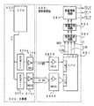
図2は、スロットマシン500に備えられる主基板(遊技制御基板)600の回路構成の一例を示すブロック図である。主基板には、この実施の形態では、図2に示すような遊技の制御を行う主基板600と、この主基板600とほぼ同一の構成を有しておりテストコマンドの出力を実行する動作確認用の主基板600A(なお、本例では、特に動作確認用の主基板600Aの各構成部分について説明する場合には、遊技を制御する主基板600の各構成に付与されている符号に「A」を付加した符号を付与して説明する。)とが用いられる。動作確認用の主基板600Aは、遊技の制御を行う主基板600が備える構成のうち少なくともテストコマンドの送信に必要な構成を備えている。本例では、主基板600というときには、動作確認用の主基板600Aをも含むことがある。遊技を制御する主基板600は、この実施の形態ではテストコマンドを出力しない構成とされる。従って、遊技の制御には不用なデータであるテストコマンドに関するデータは、遊技を制御する主基板600のROM604には記憶保持されていない。よって、遊技を制御する主基板600のROM604の記憶容量を増加させる必要はない。なお、動作確認用の主基板600AのROM604Aには、テストコマンドに関するデータが記憶保持されている。各主基板600,604Aはそれぞれ着脱可能な構成とされ、テスト(動作確認のテスト)を行うときに、遊技の制御を行う主基板600に換えて動作確認用の主基板600Aがテストの対象となる電気部品制御手段に接続される。
FIG. 2 is a block diagram showing an example of a circuit configuration of a main board (game control board) 600 provided in the
図2には、表示制御基板630、リールユニット650、ランプ制御基板660および音制御基板680も示されている。なお、主基板600には電源基板や中継基板などの他の基板も接続されるが、図2には示されていない。主基板600には、制御プログラムに従ってスロットマシン500を制御する基本回路601と、スタートスイッチ525からの信号、および各ストップスイッチ526a〜526cからのストップスイッチ信号を基本回路601に与えるスイッチ回路606と、図柄表示リール514a〜514cを回転させるリールモータ651等を基本回路601からの指令に従って駆動するモータ回路607とが搭載されている。モータ回路607は、各図柄表示リール514a〜514cの回転や停止を制御するために、リール制御信号をリールモータ651に出力する。
FIG. 2 also shows a display control board 630, a
基本回路601は、プログラムに従って制御動作を行うCPU602、ワークメモリとして使用される記憶手段の一例であるRAM603、ゲーム制御用のプログラム等を記憶するROM604およびI/Oポート部605を含む。この実施の形態では、RAM603,ROM604はCPU602に内蔵されている。すなわち、CPU602は、1チップマイクロコンピュータである。なお、1チップマイクロコンピュータは、少なくともRAM603が内蔵されていればよく、ROM604およびI/Oポート部605は外付けであっても内蔵されていてもよい。また、I/Oポート部605は、マイクロコンピュータにおける情報入出力可能な端子である。
The
さらに、主基板600には、大当り乱数(ボーナスゲームの発生を許容するか否かの判定に用いられる乱数)などの各乱数を発生させる乱数発生回路612と、スタートスイッチ信号の受信に応じて乱数発生回路612から乱数を取得して基本回路601に出力するサンプリング回路613とが設けられている。なお、主基板600には、図示はしないが、表示制御基板630、ランプ制御基板660および音制御基板680のそれぞれに対応して、例えば8ビットのデータと1ビットのストローブ信号(INT信号)が出力される出力バッファ回路が複数設けられている。
Further, the
この実施の形態では、表示制御基板630に搭載されている表示制御手段が、スロットマシン500に設けられているLCD541の表示制御を行う。LCD541には、表示制御手段の制御によって、入賞予告に関する表示や、遊技状態や遊技方法を報知するための表示などの様々な情報が表示される。また、ランプ制御基板660に搭載されているランプ制御手段が、スロットマシン500に設けられているリールランプ652a〜652i、各種のサイドランプ550等や、蛍光灯671の点灯制御を行う。さらに、音制御基板680に搭載されている音制御手段が、スロットマシン500に設けられているスピーカ531,545a,545bの音出力制御を行う。
In this embodiment, display control means mounted on the display control board 630 performs display control of the
表示制御手段は、この例では可変表示領域502の表示制御を行わないが、主基板600からの表示制御コマンドに応じてLCD541に所定の表示を行うための制御を行う。また、ランプ制御基板660および音制御基板680は、例えば表示制御基板630の制御に同期して発光体や音声出力に関する制御を実行する。
In this example, the display control means does not perform display control of the
リールユニット650には、リールモータ651と、リールランプ652a〜652iと、リールセンサ653とが格納されている。リールモータ651は、各リール514a〜514cを回転させるためのモータである。リールランプ652〜652iは、それぞれ、各リール514a〜514cの内部に設けられ、各リール514a〜514cに描かれた図柄のうち、可変表示領域502にて視認される図柄をリールの内側から照らすためのランプである。リールランプ652a〜652cは、それぞれ、リール514aに描かれた図柄のうちの可変表示領域502にて視認可能な上図柄、中図柄、下図柄を照らすランプである。また、リールランプ652d〜652fは、それぞれ、リール514bに描かれた図柄のうちの可変表示領域502にて視認可能な上図柄、中図柄、下図柄を照らすランプである。さらに、リールランプ652g〜652iは、それぞれ、リール514cに描かれた図柄のうちの可変表示領域502にて視認可能な上図柄、中図柄、下図柄を照らすランプである。リールセンサ653は、各リール514a〜514cの回転状態や回転数などを感知するためのセンサである。
The
図2に示されているように、スタートスイッチ525の検出信号は、スイッチ回路606を介して基本回路601に入力するとともに、サンプリング回路613に入力する。基本回路601は、スタートスイッチ525の検出信号が入力すると、モータ回路607を介してリール制御信号を出力する。リール制御信号によってリールモータ651が駆動して、各リール514a〜514cが回転を開始する。
As shown in FIG. 2, the detection signal of the
サンプリング回路613は、スタートスイッチ525の検出信号が入力したタイミングで、乱数発生回路612から1個の乱数を抽出して基本回路601に出力する。CPU602は、サンプリング回路613から受けた乱数と、ROM604内に格納されている入賞役別の入賞判定テーブルとを参照して、入賞の発生を許容するか否かを入賞役別に決定し、その決定結果をRAM603に記憶させる。このようにして、スタートスイッチ525が操作されたタイミングで、入賞役の当選の有無が決定される。CPU602は、その後、入賞役別の当選結果に応じてリール514a〜514cを制御する。
The
さらに、CPU602は、スタートスイッチ525の検出信号が入力されたことに対応して、バッファ回路611を介して表示制御基板630などの各基板にゲームの開始を特定可能な制御コマンド(予告演出パターンコマンド)を出力する。表示制御基板630は、受信した制御コマンドにもとづいて、ゲーム開始時に対応して定められた演出パターンに従って、LCD541などを制御する。また、ランプ制御基板660は、受信した制御コマンドにもとづいて、ゲーム開始時に対応して定められた点灯パターンに従って、サイドランプ550等などを制御する。さらに、音制御基板680は、受信した制御コマンドにもとづいて、ゲーム開始時に対応して定められた音出力パターンに従って、スピーカ531,545a,545bなどを制御する。
Further, in response to the detection signal of the
また、CPU602は、ストップスイッチ526a〜526cの検出信号(ストップスイッチ信号)が入力すると、モータ回路607を介して、ストップスイッチ信号に対応するリール(リール514a〜514cのうちのいずれか)を停止させるためのリール制御信号を、リールモータ651に向けて出力する。また、CPU602は、ストップスイッチ信号の入力に応じて、バッファ回路を介して表示制御基板630などの各基板にリール514a〜514cの停止時期を特定可能な制御コマンド(告知演出パターンコマンド)を出力する。各基板630,660,680は、受信した制御コマンドにもとづいて、リール514a〜514cの停止時期に対応して定められた演出パターンに従って、LCD541や、サイドランプ550等や、スピーカ531,545a,545bなどを制御する。
Further, when the detection signal (stop switch signal) of the stop switches 526a to 526c is input, the
なお、上述したスロットマシン500では、可変表示領域502の表示制御を主基板600が行う構成としていたが、表示制御基板630が行うようにしてもよい。この場合、モータ回路を表示制御基板630に備えるようにして、主基板600からの表示制御コマンドに応じて、表示制御基板630がモータ回路を制御するようにすればよい。このように構成すれば、表示制御基板630は、モータ回路を制御してリール制御信号をリールモータ651に出力することで、各図柄表示リール514a〜514cの回転や停止を制御することが可能となる。
In the
図3は、表示制御基板630内の回路構成を、LCD541、主基板600の出力ポート(ポート0,2)605a,605cおよび出力バッファ回路614a,614cとともに示すブロック図である。出力ポート(出力ポート2)605cからは8ビットのデータが出力され、出力ポート605aからは1ビットのストローブ信号(INT信号)が出力される。
FIG. 3 is a block diagram showing a circuit configuration in the display control board 630 together with the
表示制御用CPU631は、制御データROM632に格納されたプログラムに従って動作し、主基板600からノイズフィルタ637および入力バッファ回路635Bを介してINT信号が入力されると、入力バッファ回路635Aを介して表示制御コマンドを受信する。入力バッファ回路635A,635Bとして、例えば汎用ICである74HC540,74HC14を使用することができる。なお、表示制御用CPU631がI/Oポートを内蔵していない場合には、入力バッファ回路635A,635Bと表示制御用CPU631との間に、I/Oポートが設けられる。
The display control CPU 631 operates according to a program stored in the
そして、表示制御用CPU631は、受信した表示制御コマンドに従って、LCD541に表示される画面の表示制御を行う。具体的には、表示制御コマンドに応じた指令をVDP633に与える。VDP633は、キャラクタROM640から必要なデータを読み出す。VDP633は、入力したデータに従ってLCD541に表示するための画像データを生成し、R,G,B信号および同期信号をLCD541に出力する。
Then, the display control CPU 631 performs display control of the screen displayed on the
なお、図3には、VDP633をリセットするためのリセット回路638、VDP633に動作クロックを与えるための発振回路639、および使用頻度の高い画像データを格納するキャラクタROM640も示されている。キャラクタROM640に格納される使用頻度の高い画像データとは、例えば、LCD541に表示される人物、動物、または、文字、図形もしくは記号等からなる画像などである。
FIG. 3 also shows a reset circuit 638 for resetting the
入力バッファ回路635A,635Bは、主基板600から表示制御基板630へ向かう方向にのみ信号を通過させることができる。従って、表示制御基板630側から主基板600側に信号が伝わる余地はない。すなわち、入力バッファ回路635A,635Bは、入力ポートとともに不可逆性情報入力手段を構成する。表示制御基板630内の回路に不正改造が加えられても、不正改造によって出力される信号が主基板600側に伝わることはない。
The
なお、出力ポート605a,605cの出力をそのまま表示制御基板630に出力してもよいが、単方向にのみ信号伝達可能な出力バッファ回路614a,614cを設けることによって、主基板600から表示制御基板630への一方向性の信号伝達をより確実にすることができる。すなわち、出力バッファ回路614a,614cは、出力ポートとともに不可逆性情報出力手段を構成する。
The outputs of the
また、高周波信号を遮断するノイズフィルタ637として、例えば3端子コンデンサやフェライトビーズが使用されるが、ノイズフィルタ637の存在によって、表示制御コマンドに基板間でノイズが乗ったとしても、その影響は除去される。なお、主基板600のバッファ回路614a,614cの出力側にもノイズフィルタを設けてもよい。
For example, a three-terminal capacitor or a ferrite bead is used as the noise filter 637 that cuts off the high-frequency signal. However, even if noise is added between the substrates due to the presence of the noise filter 637, the influence is removed. Is done. A noise filter may also be provided on the output side of the
図4は、主基板600およびランプ制御基板660における信号送受信部分を示すブロック図である。この実施の形態では、遊技パネル501の外側に設けられているサイドランプ528a,528b、ランプ542〜544、およびサイドランプ550〜553などと、遊技パネル501に設けられている1枚賭けランプ503、2枚賭け装飾ランプ504、3枚賭けランプ505、ゲームオーバーランプ506、リプレイランプ507、ウェイトランプ508、スタートランプ509、メダル投入指示ランプ510およびリールランプ652a〜652iなどの点灯/消灯とを示すランプ制御コマンドが主基板600からランプ制御基板660に出力される。また、この実施の形態では、クレジット表示器511、ゲーム回数表示器512およびペイアウト表示器513に表示される数値を示すランプ制御コマンドが主基板600からランプ制御基板660に出力される。
FIG. 4 is a block diagram showing signal transmission / reception portions of
図4に示すように、ランプ制御に関するランプ制御コマンドは、基本回路601におけるI/Oポート部605の出力ポート(出力ポート0,3)605a,605dから出力される。出力ポート(出力ポート3)605dは8ビットのデータを出力し、出力ポート605aは1ビットのINT信号を出力する。ランプ制御基板660において、主基板600からの制御コマンドは、入力バッファ回路665A,665Bを介してランプ制御用CPU661に入力する。なお、ランプ制御用CPU661がI/Oポートを内蔵していない場合には、入力バッファ回路665A,665Bとランプ制御用CPU661との間に、I/Oポートが設けられる。
As shown in FIG. 4, the lamp control command related to the lamp control is output from the output ports (
ランプ制御基板660において、ランプ制御用CPU661は、各制御コマンドに応じて定義されているサイドランプ528a,528b、ランプ542〜544、およびサイドランプ550〜553などの点灯/消灯パターンに従って、サイドランプ528a,528b、ランプ542〜544、およびサイドランプ550〜553などに対して点灯/消灯信号を出力する。点灯/消灯信号は、サイドランプ528a,528b、ランプ542〜544、およびサイドランプ550〜553などに出力される。なお、点灯/消灯パターンは、ランプ制御用CPU661の内蔵ROMまたは外付けROMに記憶されている。
In the lamp control board 660, the lamp control CPU 661 follows the lighting / extinguishing patterns of the
主基板600において、CPU602は、BETスイッチ521またはMAXBETスイッチ522が押下されるなどして賭数が設定されると、その賭け数に応じて1枚賭けランプ503、2枚賭け装飾ランプ504、または3枚賭けランプ505の点灯を指示する制御コマンドを出力し、さらに、スタートランプ509の点灯を指示する制御コマンドを出力する。ランプ制御基板660において、各制御コマンドは、入力バッファ回路665A,665Bを介してランプ制御用CPU661に入力する。ランプ制御用CPU661は、それらの制御コマンドに応じて、1枚賭けランプ503、2枚賭け装飾ランプ504、3枚賭けランプ505およびスタートランプ509を点灯/消灯する。なお、点灯/消灯パターンは、ランプ制御用CPU661の内蔵ROMまたは外付けROMに記憶されている。
In the
さらに、ランプ制御用CPU661は、制御コマンドに応じて、ゲームオーバーランプ506、リプレイランプ507、ウェイトランプ508およびメダル投入指示ランプ510などに対して点灯/消灯信号を出力する。また、ランプ制御用CPU661は、制御コマンドに応じて、クレジット表示器511、ゲーム回数表示器512およびペイアウト表示器513に対して所定の数値を表示させるための点灯/消灯信号を出力する。
Further, the lamp control CPU 661 outputs a turn-on / off signal to the game over
入力バッファ回路665A,665Bとして、例えば、汎用のCMOS−ICである74HC540,74HC14が用いられる。入力バッファ回路665A,665Bは、主基板600からランプ制御基板660へ向かう方向にのみ信号を通過させることができる。従って、ランプ制御基板660側から主基板600側に信号が伝わる余地はない。たとえ、ランプ制御基板660内の回路に不正改造が加えられても、不正改造によって出力される信号がメイン基板31側に伝わることはない。なお、入力バッファ回路665A,665Bの入力側にノイズフィルタを設けてもよい。
As the input buffer circuits 665A and 665B, for example, general-purpose CMOS-ICs 74HC540 and 74HC14 are used. The input buffer circuits 665A and 665B can pass signals only in the direction from the
また、主基板600において、出力ポート605a,605dの外側にバッファ回路614a,614dが設けられている。バッファ回路614a,614dとして、例えば、汎用のCMOS−ICである74HC250,74HC14が用いられる。このような構成によれば、外部から主基板600の内部に入力される信号が阻止されるので、ランプ制御基板660から主基板600に信号が与えられる可能性がある信号ラインをさらに確実になくすことができる。なお、バッファ回路614a,614dの出力側にノイズフィルタを設けてもよい。
In the
図5は、主基板600における音制御コマンドの信号送信部分および音制御基板680の構成例を示すブロック図である。この実施の形態では、遊技進行に応じて、遊技パネル501の外側に設けられているスピーカ545a,545b,531の音声出力を指示するための音制御コマンドが、主基板600から音制御基板680に出力される。
FIG. 5 is a block diagram showing a configuration example of the sound control command signal transmission part of the
図5に示すように、音制御コマンドは、基本回路601におけるI/Oポート部605の出力ポート(出力ポート0,4)605a,605eから出力される。出力ポート(出力ポート4)605eからは8ビットのデータが出力され、出力ポート605aからは1ビットのINT信号が出力される。音制御基板680において、主基板600からの各信号は、入力バッファ回路685A,685Bを介して音制御用CPU681に入力する。なお、音制御用CPU681がI/Oポートを内蔵していない場合には、入力バッファ回路685A,685Bと音制御用CPU681との間に、I/Oポートが設けられる。
As shown in FIG. 5, the sound control command is output from the output ports (
そして、例えばディジタルシグナルプロセッサによる音声合成回路682は、音制御用CPU681の指示に応じた音声や効果音を発生し音量切替回路683に出力する。音量切替回路683は、音制御用CPU681の出力レベルを、設定されている音量に応じたレベルにして音量増幅回路684に出力する。音量増幅回路684は、増幅した音声信号をスピーカ545a,545b,531に出力する。
Then, for example, a voice synthesis circuit 682 using a digital signal processor generates a voice or a sound effect according to an instruction from the sound control CPU 681 and outputs it to the volume switching circuit 683. The volume switching circuit 683 sets the output level of the sound control CPU 681 to a level corresponding to the set volume and outputs it to the volume amplification circuit 684. The volume amplifier circuit 684 outputs the amplified audio signal to the
入力バッファ回路685A,685Bとして、例えば、汎用のCMOS−ICである74HC540,74HC14が用いられる。入力バッファ回路685A,685Bは、主基板600から音制御基板680へ向かう方向にのみ信号を通過させることができる。よって、音制御基板680側から主基板600側に信号が伝わる余地はない。従って、音制御基板680内の回路に不正改造が加えられても、不正改造によって出力される信号が主基板600側に伝わることはない。なお、入力バッファ回路685A,685Bの入力側にノイズフィルタを設けてもよい。
As the
また、主基板600において、出力ポート605a,605eの外側にバッファ回路614a,614eが設けられている。バッファ回路614a,614eとして、例えば、汎用のCMOS−ICである74HC250,74HC14が用いられる。このような構成によれば、外部から主基板600の内部に入力される信号が阻止されるので、音制御基板680から主基板600に信号が与えられる可能性がある信号ラインをさらに確実になくすことができる。なお、バッファ回路614a,614eの出力側にノイズフィルタを設けてもよい。
In the
上述したように、表示制御基板630、ランプ制御基板660および音制御基板680にコマンドを送出するために、主基板600の出力ポート(出力ポート0)605aからINT信号が各電気部品制御基板に出力される。この場合、例えば、出力ポート605aは8ビット構成であって、ビット0が図示しない払出制御基板へのINT信号、ビット1が表示制御基板630へのINT信号、ビット2がランプ制御基板660へのINT信号、ビット3が音制御基板680へのINT信号の出力用に用いられる。
As described above, in order to send commands to the display control board 630, the lamp control board 660, and the
次にスロットマシンの動作について説明する。
図6は、主基板600におけるCPU602が実行するメイン処理を示すフローチャートである。スロットマシンに対して電源が投入され、CPU602が起動すると、メイン処理において、CPU602は、まず、必要な初期設定を行う。
Next, the operation of the slot machine will be described.
FIG. 6 is a flowchart showing main processing executed by the
初期設定処理において、CPU602は、まず、割込禁止に設定する(ステップS1)。次に、割込モードを割込モード2に設定し(ステップS2)、スタックポインタにスタックポインタ指定アドレスを設定する(ステップS3)。そして、内蔵デバイスレジスタの初期化を行う(ステップS4)。また、内蔵デバイス(内蔵周辺回路)であるCTC(カウンタ/タイマ)およびPIO(パラレル入出力ポート)の初期化(ステップS5)を行った後、RAMをアクセス可能状態に設定する(ステップS6)。
In the initial setting process, the
この実施の形態で用いられるCPU602は、I/Oポート(PIO)およびタイマ/カウンタ回路(CTC)も内蔵している。また、CTCは、2本の外部クロック/タイマトリガ入力CLK/TRG2,3と2本のタイマ出力ZC/TO0,1を備えている。
The
この実施の形態で用いられているCPU602には、マスク可能な割込(INT)のモードとして以下の3種類のモードが用意されている。なお、マスク可能な割込が発生すると、CPU602は、自動的に割込禁止状態に設定するとともに、プログラムカウンタの内容をスタックにセーブする。
In the
割込モード0:割込要求を行った内蔵デバイスがRST命令(1バイト)またはCALL命令(3バイト)をCPUの内部データバス上に送出する。よって、CPU602は、RST命令に対応したアドレスまたはCALL命令で指定されるアドレスの命令を実行する。リセット時に、CPU602は自動的に割込モード0になる。よって、割込モード1または割込モード2に設定したい場合には、初期設定処理において、割込モード1または割込モード2に設定するための処理を行う必要がある。
Interrupt mode 0: The built-in device that has issued the interrupt request sends an RST instruction (1 byte) or a CALL instruction (3 bytes) onto the internal data bus of the CPU. Therefore, the
割込モード1:割込が受け付けられると、常に0038(h)番地に飛ぶモードである。 Interrupt mode 1: In this mode, when an interrupt is accepted, the mode always jumps to address 0038 (h).
割込モード2:CPU602の特定レジスタ(Iレジスタ)の値(1バイト)と内蔵デバイスが出力する割込ベクタ(1バイト:最下位ビット0)から合成されるアドレスが、割込番地を示すモードである。すなわち、割込番地は、上位アドレスが特定レジスタの値とされ下位アドレスが割込ベクタとされた2バイトで示されるアドレスである。従って、任意の(飛び飛びではあるが)偶数番地に割込処理を設置することができる。各内蔵デバイスは割込要求を行うときに割込ベクタを送出する機能を有している。
Interrupt mode 2: A mode in which an address synthesized from the value (1 byte) of a specific register (I register) of the
よって、割込モード2に設定されると、各内蔵デバイスからの割込要求を容易に処理することが可能になり、また、プログラムにおける任意の位置に割込処理を設置することが可能になる。さらに、割込モード1とは異なり、割込発生要因毎のそれぞれの割込処理を用意しておくことも容易である。上述したように、この実施の形態では、初期設定処理のステップS2において、CPU602は割込モード2に設定される。
Therefore, when the interrupt
そして、電源断時にバックアップRAM領域のデータ保護処理(例えばパリティデータの付加等の停電発生NMI処理)が行われたか否か確認する(ステップS7)。この実施の形態では、不測の電源断が生じた場合には、バックアップRAM領域のデータを保護するための処理が行われている。そのような保護処理が行われていた場合をバックアップありとする。バックアップなしを確認したら、CPU602は初期化処理を実行する。
Then, it is confirmed whether or not data protection processing (for example, power failure occurrence NMI processing such as addition of parity data) has been performed in the backup RAM area when the power is turned off (step S7). In this embodiment, when an unexpected power failure occurs, processing for protecting data in the backup RAM area is performed. When such protection processing is performed, it is assumed that there is a backup. When it is confirmed that there is no backup, the
この実施の形態では、バックアップRAM領域にバックアップデータがあるか否かは、電源断時にバックアップRAM領域に設定されるバックアップフラグの状態によって確認される。この例では、図7に示すように、バックアップフラグ領域に「55H」が設定されていればバックアップあり(オン状態)を意味し、「55H」以外の値が設定されていればバックアップなし(オフ状態)を意味する。 In this embodiment, whether or not there is backup data in the backup RAM area is confirmed by the state of the backup flag set in the backup RAM area when the power is turned off. In this example, as shown in FIG. 7, if “55H” is set in the backup flag area, it means that there is a backup (ON state), and if a value other than “55H” is set, there is no backup (OFF). State).
バックアップありを確認したら、CPU602は、バックアップRAM領域のデータチェック(この例ではパリティチェック)を行う。不測の電源断が生じた後に復旧した場合には、バックアップRAM領域のデータは保存されていたはずであるから、チェック結果は正常になる。チェック結果が正常でない場合には、内部状態を電源断時の状態に戻すことができないので、停電復旧時でない電源投入時に実行される初期化処理を実行する。
After confirming that there is a backup, the
チェック結果が正常であれば(ステップS8)、CPU602は、遊技制御手段の内部状態と表示制御手段等の電気部品制御手段の制御状態を電源断時の状態に戻すための遊技状態復旧処理を行う(ステップS9)。そして、バックアップRAM領域に保存されていたPC(プログラムカウンタ)の退避値がPCに設定され、そのアドレスに復帰する。
If the check result is normal (step S8), the
初期化処理では、CPU602は、まず、RAMクリア処理を行う(ステップS11)。また、所定の作業領域(例えば、乱数カウンタ、判定用バッファ、コマンド格納ポインタなど)に初期値を設定する初期値設定処理も行われる。さらに、サブ基板(表示制御基板630、ランプ制御基板660、払出制御基板、音制御基板680)を初期化するための処理を実行する(ステップS13)。サブ基板を初期化する処理とは、例えば初期設定のためのコマンドを送出する処理である。
In the initialization process, the
そして、2ms毎に定期的にタイマ割込がかかるようにCPU602に設けられているCTCのレジスタの設定が行われる(ステップS14)。すなわち、初期値として2msに相当する値が所定のレジスタ(時間定数レジスタ)に設定される。そして、初期設定処理のステップS1において割込禁止とされているので、初期化処理を終える前に割込が許可される(ステップS15)。
Then, a CTC register provided in the
初期化処理の実行(ステップS11〜S15)が完了すると、メイン処理で、上述した大当り乱数や後述する告知用乱数を更新するための乱数更新処理(ステップS16)が実行されるループ処理に移行する。 When the execution of the initialization process (steps S11 to S15) is completed, the main process proceeds to a loop process in which a random number update process (step S16) for updating the jackpot random number described above or a notification random number described later is executed. .
この実施の形態では、CPU602の内蔵CTCが繰り返しタイマ割込を発生するように設定される。この実施の形態では、繰り返し周期は2msに設定される。そして、タイマ割込が発生すると、図8に示すように、CPU602は、ステップS21〜S27の遊技制御処理を実行する。
In this embodiment, the built-in CTC of the
遊技制御処理において、CPU602は、まず、スイッチ回路606を介して、スタートスイッチ525やストップスイッチ526a〜526cなどの各スイッチの状態を入力し、それらの状態判定を行う(スイッチ処理:ステップS21)。具体的には、各スイッチの状態に応じて対応するフラグのセットなどを行う。
In the game control process, the
次いで、スロットマシンの内部に備えられている自己診断機能によって種々の異常診断処理が行われ、その結果に応じて必要ならば警報が発せられる(エラー処理:ステップS22)。 Next, various abnormality diagnosis processing is performed by a self-diagnosis function provided in the slot machine, and an alarm is issued if necessary according to the result (error processing: step S22).
次に、遊技制御に用いられる大当り乱数や告知演出用の乱数等の各乱数を示す各カウンタを更新する処理を行う(ステップS23)。告知用乱数は、遊技状態(ボーナスはずれ、ビッグボーナス内部当選、レギュラーボーナス内部当選など)に応じて、例えば告知演出を行うか否か、および告知演出の内容を決定するために用いられる。また、遊技効果を高めるために、上記の乱数以外の乱数も用いられている。ステップS23では、CPU602は、大当り乱数や告知用乱数を生成するためのカウンタのカウントアップ(1加算)を行う。
Next, a process of updating each counter indicating each random number such as a big hit random number used for game control or a random number for announcement effect is performed (step S23). The random number for notification is used to determine, for example, whether or not to perform a notification effect and the content of the notification effect according to the gaming state (bonus loss, big bonus internal winning, regular bonus internal winning, etc.). Further, random numbers other than the above random numbers are also used in order to enhance the game effect. In step S23, the
さらに、CPU602は、リール制御プロセス処理を行う(ステップS24)。リール制御プロセス制御では、遊技状態に応じてスロットマシンを所定の順序で制御するためのリール制御プロセスフラグに従って該当する処理が選び出されて実行される。そして、リール制御プロセスフラグの値は、遊技状態に応じて各処理中に更新される。リール制御プロセス処理では、例えば、スタートスイッチ525のオンフラグがセット(ステップS21のスイッチ処理でセットされる)されていたことに応じて、大当り乱数が抽出されて内部当選とすることを許容するか否かが決定されたり、告知用乱数が抽出されて予告演出の内容が決定されたり、リールモータ651の駆動が開始されたりする処理が行われる。また、例えば、ストップスイッチ526a〜526cのオンフラグが全てセット(ステップS21のスイッチ処理でセットされる)されていたことに応じて、リールモータ651の駆動が停止されたり、停止図柄にもとづいて内部当選とするか否かが判定されたり、告知用乱数が抽出されて内部当選となったか否かなどの告知演出の内容が決定されたりする処理が行われる。
Further, the
次いで、CPU602は、LCD541の表示制御に関する表示制御コマンドをRAM603の所定の領域に設定して表示制御コマンドを送出する処理を行う(表示制御コマンド制御処理:ステップS25)。
Next, the
さらに、CPU602は、例えばホール管理用コンピュータに供給されるボーナスゲームの実行中であるが否かなどの各種の情報を出力する情報出力処理を行う(ステップS26)。
Further, the
そして、CPU602は、停止図柄の結果にもとづくメダル数の設定などを行う払出メダル設定処理を実行する(ステップS27)。具体的には、停止図柄が所定の並び態様で揃ったことに応じて払出制御基板に払出制御コマンドを出力する。払出制御基板に搭載されている払出制御用CPUは、払出制御コマンドに応じてメダル払出装置を駆動する。なお、主基板600が払出制御をも実行する構成とした場合には、主基板600は、停止図柄が所定の並び態様で揃ったことに応じてメダル払出装置を駆動する。
Then, the
以上の制御によって、この実施の形態では、遊技制御処理は2ms毎に起動されることになる。なお、この実施の形態では、タイマ割込処理で遊技制御処理が実行されるが、タイマ割込処理では例えば割込が発生したことを示すフラグのセットのみがなされ、遊技制御処理はメイン処理において実行されるようにしてもよい。 With the above control, in this embodiment, the game control process is started every 2 ms. In this embodiment, the game control process is executed by the timer interrupt process. In the timer interrupt process, for example, only a flag indicating that an interrupt has occurred is set, and the game control process is performed in the main process. It may be executed.
また、メイン処理においてタイマ割込の設定がなされ、ループ処理の実行中にCPU602の内部タイマが定期的に発生するタイマ割込にもとづくタイマ割込処理で遊技制御処理が実行されるので、遊技制御処理の全てが確実に実行される。つまり、遊技制御処理の全てが実行されるまでは、ループ処理に戻らないので、遊技制御処理中の全ての各処理が実行完了することは保証されている。
In addition, the timer interrupt is set in the main process, and the game control process is executed in the timer interrupt process based on the timer interrupt that is periodically generated by the internal timer of the
以上に説明したように、この実施の形態では、CTCやPIOを内蔵するCPU602に対して、初期設定処理で割込モード2が設定される。従って、内蔵CTCを用いた定期的なタイマ割込処理を容易に実現できる。また、タイマ割込処理をプログラム上の任意の位置に設置できる。また、内蔵PIOを用いたスイッチ検出処理等を容易に割込処理で実現できる。その結果、プログラム構成が簡略化され、プログラム開発工数が低減する等の効果を得ることができる。
As described above, in this embodiment, the interrupt
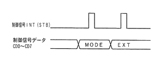
次に、主基板600から表示制御基板630に対する表示制御コマンドの送出について説明する。図9は、主基板600から表示制御基板630に送信される表示制御コマンドの信号線を示す説明図である。図9に示すように、この実施の形態では、表示制御コマンドは、表示制御信号D0〜D7の8本の信号線で主基板600から表示制御基板630に送信される。また、主基板600と表示制御基板630との間には、ストローブ信号を送信するための表示制御INT信号の信号線も配線されている。
Next, transmission of a display control command from the
この実施の形態では、表示制御コマンドは2バイト構成であり、図10に示すように、1バイト目はMODE(コマンドの分類)を表し、2バイト目はEXT(コマンドの種類)を表す。MODEデータの先頭ビット(ビット7)は必ず「1」とされ、EXTデータの先頭ビット(ビット7)は必ず「0」とされる。なお、図10に示されたコマンド形態は一例であって他のコマンド形態を用いてもよい。また、この例では、制御コマンドが2つの制御信号で構成されていることになるが、制御コマンドを構成する制御信号数は、1であってもよいし、3以上の複数であってもよい。 In this embodiment, the display control command has a 2-byte configuration. As shown in FIG. 10, the first byte represents MODE (command classification), and the second byte represents EXT (command type). The first bit (bit 7) of the MODE data is always “1”, and the first bit (bit 7) of the EXT data is always “0”. Note that the command form shown in FIG. 10 is an example, and other command forms may be used. In this example, the control command is composed of two control signals. However, the number of control signals constituting the control command may be one or a plurality of three or more. .
図11は、表示制御基板630に対する制御コマンドを構成する8ビットの制御信号とINT信号(ストローブ信号)との関係を示すタイミング図である。図11に示すように、MODEまたはEXTのデータが出力ポートに出力されてから、所定期間が経過すると、CPU602は、データ出力を示す信号であるINT信号をオン状態にする。また、そこから所定期間が経過するとINT信号をオフ状態にする。
FIG. 11 is a timing chart showing the relationship between an 8-bit control signal and an INT signal (strobe signal) that constitute a control command for the display control board 630. As shown in FIG. 11, when a predetermined period elapses after MODE or EXT data is output to the output port, the
なお、ここでは、表示制御コマンドについて説明したが、他のサブ基板(払出制御基板、ランプ制御基板660、音制御基板680)に送出される各制御コマンドも、図10および図11に示された形態と同一である。 Although the display control command has been described here, the control commands sent to other sub-boards (payout control board, lamp control board 660, sound control board 680) are also shown in FIGS. The form is the same.
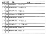
図12は、遊技の制御を行う主基板600から表示制御基板630に送出される表示制御コマンドの内容の一例を示す説明図である。表示制御基板630は、表示制御コマンドを受信すると、表示制御コマンドの内容に応じてLCD541を用いて所定情報の表示を行う。なお、コマンドの受信処理などについては後で詳しく説明する。図12に示す例において、コマンドB100(H)は、はずれ予告表示を行うことを指定する表示制御コマンドである。コマンドB101(H)〜コマンドB104(H)は、小役予告1〜小役予告4の表示態様での小役予告表示を指定する表示制御コマンドである。コマンドB100(H)〜コマンドB104(H)は、スタートスイッチ525の押下に応じて抽出される告知用乱数や遊技状態にもとづいて選択されて出力される。
FIG. 12 is an explanatory diagram showing an example of the contents of a display control command sent from the
コマンド9300(H)〜コマンド9302(H)は、LCD541におけるボーナスフラグ告知1〜ボーナスフラグ告知3の表示態様での告知表示を指定する表示制御コマンドである。コマンド9400(H)〜コマンド9402(H)は、LCD541におけるボーナスフラグはずれ告知1〜ボーナスフラグはずれ告知3の表示態様でのはずれ予告表示を指定する表示制御コマンドである。コマンド9300(H)〜コマンド9302(H)およびコマンド9400(H)〜コマンド9402(H)は、回転していた図柄表示リール514a〜514aの全てが停止したことに応じて(停止図柄がリプレイ図柄、または小役内部当選図柄であるときを除く)抽出される告知用乱数や遊技状態にもとづいて選択されて出力される。
Command 9300 (H) to command 9302 (H) are display control commands for designating notification display in the display mode of
なお、図12には示されていないが、LCD541の他の表示内容を指定する表示制御コマンドや、客待ちデモンストレーションを指示する表示制御コマンドなどの他の表示制御コマンドもあらかじめ用意され、遊技状態に応じて出力される。
Although not shown in FIG. 12, other display control commands such as a display control command for specifying other display contents of the
表示制御基板630の表示制御手段は、主基板600の遊技制御手段から上述した表示制御コマンドを受信すると図12に示された内容に応じてLCD541によって所定の演出を実行する。
When the display control means of the display control board 630 receives the above-described display control command from the game control means of the
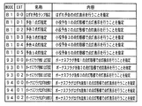
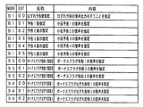
図13は、テストの実行の際に動作確認用の主基板600Aから表示制御基板630に送出される表示制御コマンドの内容の一例を示す説明図である。この例では、テストコマンド1〜9が用意されている。表示制御基板630の表示制御用CPU631は、主基板600Aからテストコマンド1〜9のいずれかを受信すると、図13に示す内容欄に記載された処理を行う。 FIG. 13 is an explanatory diagram showing an example of the contents of a display control command sent from the main board 600A for operation confirmation to the display control board 630 when the test is executed. In this example, test commands 1 to 9 are prepared. When receiving any one of the test commands 1 to 9 from the main board 600A, the display control CPU 631 of the display control board 630 performs the processing described in the contents column shown in FIG.
この例では、以下に示すテストコマンド1〜8は、主基板600Aと表示制御基板630とを接続する通信ケーブルのビット0〜ビット7に対応している。従って、LCD541においてテストコマンド1〜8に応じた制御が実行されない場合には、通信ケーブルの断線が発生していることが推測できる。
In this example, test commands 1 to 8 shown below correspond to
図13に示す例において、テストコマンドFF00(H)は、LCD541に色調調整用のカラーバー画面を表示することを指示するための表示制御コマンドである。テストコマンド2(FF01(H))〜テストコマンド9(FF70(H))は、LCD541における表示位置の調整の確認を行うための表示(単一色の画面表示)を指示するための表示制御コマンドである。具体的には、テストコマンドFF01(H)は「グレー」の画面を、テストコマンドFF02(H)は「赤」の画面を、テストコマンドFF04(H)は「緑」の画面を、テストコマンドFF08(H)は「青」の画面を、テストコマンドFF10(H)は「シアン」の画面を、テストコマンドFF20(H)は「マゼンダ」の画面を、テストコマンドFF40(H)は「黄」の画面を、そしてテストコマンドFF7F(H)は「白」の画面を、それぞれLCD541に表示することを指示するための表示制御コマンドである。
In the example shown in FIG. 13, the test command FF00 (H) is a display control command for instructing to display a color bar screen for color tone adjustment on the
なお、図13には示されていないが、テストコマンドとして、例えばLCD541の液晶パネルのチェック(パネルのドット欠けの有無の確認)を行うための表示を指定する表示制御コマンドを設けるようにしてもよい。表示制御用CPU631は、液晶パネルのチェックを行うためのテストコマンドを受信すると、客待ちデモンストレーション画面(例えば、機種名表示画面、ゲームキャラクタの紹介画面など)を例えば3秒間隔で順次ループ表示する。表示内容は、通常のデモンストレーション画面表示のときと同じ内容であるが、液晶パネルのチェックの際には、確認処理を迅速に行うために例えば切替周期を早くする。 Although not shown in FIG. 13, as a test command, for example, a display control command for designating a display for checking a liquid crystal panel of the LCD 541 (confirmation of presence / absence of missing dots on the panel) may be provided. Good. When receiving a test command for checking the liquid crystal panel, the display control CPU 631 sequentially displays a customer waiting demonstration screen (for example, a model name display screen, a game character introduction screen, etc.) in a loop at intervals of 3 seconds, for example. The display content is the same as that in the normal demonstration screen display. However, when the liquid crystal panel is checked, for example, the switching cycle is increased in order to perform the confirmation process quickly.
図14は、遊技の制御を行う主基板600からランプ制御基板660に送出されるランプ制御コマンドの内容の一例を示す説明図である。ランプ制御コマンドもMODEとEXTの2バイト構成である。ランプ制御基板660は、ランプ制御コマンドを受信すると、ランプ制御コマンドが示す内容に応じた点灯/消灯パターンでランプ・LEDの点灯/消灯制御を行う。図14に示す例において、コマンドB100(H)は、はずれ予告報知時のランプ・LED表示制御パターンを指示するランプ制御コマンドである。コマンドB101(H)〜コマンドB104(H)は、小役予告1〜小役予告4の報知時のランプ・LED表示制御パターンを指示するランプ制御コマンドである。
FIG. 14 is an explanatory diagram showing an example of the contents of a lamp control command sent from the
コマンド9300(H)〜コマンド9302(H)は、ボーナスフラグ告知1〜ボーナスフラグ告知3の報知時のランプ・LED表示制御パターンを指示するランプ制御コマンドである。コマンド9400(H)〜コマンド9402(H)は、ボーナスフラグはずれ告知1〜ボーナスフラグはずれ告知3の報知時のランプ・LED表示制御パターンを指示するランプ制御コマンドである。
A command 9300 (H) to a command 9302 (H) are lamp control commands for instructing a lamp / LED display control pattern when the
なお、図14には示されていないが、クレジット表示器511、ゲーム回数表示器512、ペイアウト表示器513に所定の数値を表示をさせるためのランプ制御コマンドや、客待ちデモンストレーション時におけるランプ・LEDの表示制御パターンを指定するランプ制御コマンドなどの他のランプ制御コマンドもあらかじめ用意され、遊技状態に応じて出力される。ただし、クレジット表示器511、ゲーム回数表示器512、ペイアウト表示器513が表示制御手段で制御される場合には、上記のコマンドは、ランプ制御基板660には送出されない。
Although not shown in FIG. 14, a lamp control command for displaying a predetermined numerical value on the
また、図14には示されていないが、LCD541によってなされている他の報知時のランプ・LED表示制御パターンを指定するランプ制御コマンドや、1枚賭けランプ503、2枚賭けランプ504、3枚賭けランプ505、ゲームオーバーランプ506、リプレイランプ507、ウエイトランプ508、スタートランプ509、メダル投入指示ランプ510などのランプやLEDの点灯/消灯を指定するランプ制御コマンドなどの他のランプ制御コマンドもあらかじめ用意され、遊技状態に応じて出力される。
Further, although not shown in FIG. 14, a lamp control command for designating other lamp / LED display control patterns at the time of notification made by the
なお、コマンド93XX、94XXおよびB1XX(X=4ビットの任意の値)は、遊技進行状況に応じて遊技制御手段から送出されるランプ制御コマンドである。ランプ制御手段は、主基板600の遊技制御手段から上述したランプ制御コマンドを受信すると図14に示された内容に応じてランプ・LEDの表示状態を変更する。コマンド93XX、94XXおよびB1XXは、表示制御コマンドや音制御コマンドと例えば共通の制御状態において共通に用いられる。
The commands 93XX, 94XX, and B1XX (X = an arbitrary value of 4 bits) are ramp control commands that are sent from the game control means in accordance with the game progress status. When the lamp control means receives the above-described lamp control command from the game control means of the
図15は、テストを実行する際に動作確認用の主基板600Aからランプ制御基板660に送出されるランプ制御コマンドの内容の一例を示す説明図である。この例では、テストコマンド1〜8が用意されている。ランプ制御基板660のランプ制御手段は、動作確認用の主基板600Aからテストコマンド1〜8のいずれかを受信すると、図15に示す内容欄に記載された処理を行う。 FIG. 15 is an explanatory diagram showing an example of the contents of a lamp control command sent from the main board 600A for operation confirmation to the lamp control board 660 when the test is executed. In this example, test commands 1 to 8 are prepared. When the lamp control means of the lamp control board 660 receives any of the test commands 1 to 8 from the main board 600A for operation confirmation, it performs the processing described in the contents column shown in FIG.
本例では、テストコマンド1〜8の各EXTデータには、ビット7を除く所定のビットに、各発光体が対応付けされている。テストコマンド1〜8において、対応付けされているビットが「1」に設定されていれば、その発光体の点灯を指示することになり、対応付けされているビットが「0」に設定されていれば、その発光体の消灯を指示することになる。
In this example, in each EXT data of the test commands 1 to 8, each light emitter is associated with a predetermined
図15に示す例において、テストコマンドF0XX(H)は、リールランプ652a〜652cの点灯/消灯を指示するためのランプ制御コマンドである。
ランプ制御用CPU661は、主基板600AからテストコマンドF0XX(H)を受けると、テストコマンドF0XX(H)のEXTデータのビット0が「1」であればリールランプ652aを点灯させる制御を行い、テストコマンドF0XX(H)のEXTデータのビット0が「0」であればリールランプ652aを消灯させる制御を行う。
受信したテストコマンドF0XX(H)のEXTデータのビット3が「1」であればリールランプ652bを点灯させる制御を行い、テストコマンドF0XX(H)のEXTデータのビット3が「0」であればリールランプ652bを消灯させる制御を行う。
さらに、受信したテストコマンドF0XX(H)のEXTデータのビット6が「1」であればリールランプ652cを点灯させる制御を行い、テストコマンドF0XX(H)のEXTデータのビット6が「0」であればリールランプ652cを消灯させる制御を行う。
In the example shown in FIG. 15, the test command F0XX (H) is a lamp control command for instructing to turn on / off the reel lamps 652a to 652c.
Upon receiving the test command F0XX (H) from the main board 600A, the lamp control CPU 661 performs control to turn on the reel lamp 652a if
If
Further, if
また、テストコマンドF1XX(H)は、リールランプ652d,652eの点灯/消灯を指示するためのランプ制御コマンドである。
ランプ制御用CPU661は、主基板600AからテストコマンドF1XX(H)を受けると、テストコマンドF1XX(H)のEXTデータのビット2が「1」であればリールランプ652dを点灯させる制御を行い、テストコマンドF1XX(H)のEXTデータのビット2が「0」であればリールランプ652dを消灯させる制御を行う。
受信したテストコマンドF1XX(H)のEXTデータのビット5が「1」であればリールランプ652eを点灯させる制御を行い、テストコマンドF1XX(H)のEXTデータのビット5が「0」であればリールランプ652eを消灯させる制御を行う。
The test command F1XX (H) is a lamp control command for instructing to turn on / off the reel lamps 652d and 652e.
Upon receiving the test command F1XX (H) from the main board 600A, the lamp control CPU 661 performs control to turn on the reel lamp 652d if
If
テストコマンドF2XX(H)は、リールランプ652f,652gの点灯/消灯を指示するためのランプ制御コマンドである。
ランプ制御用CPU661は、主基板600AからテストコマンドF2XX(H)を受けると、テストコマンドF2XX(H)のEXTデータのビット0が「1」であればリールランプ652fを点灯させる制御を行い、テストコマンドF2XX(H)のEXTデータのビット0が「0」であればリールランプ652fを消灯させる制御を行う。
また、受信したテストコマンドF2XX(H)のEXTデータのビット3が「1」であればリールランプ652gを点灯させる制御を行い、テストコマンドF2XX(H)のEXTデータのビット3が「0」であればリールランプ652gを消灯させる制御を行う。
The test command F2XX (H) is a lamp control command for instructing to turn on / off the reel lamps 652f and 652g.
Upon receiving the test command F2XX (H) from the main board 600A, the lamp control CPU 661 performs control to turn on the reel lamp 652f if
If
テストコマンドF3XX(H)は、リールランプ652h,652i、およびスロットマシン上部に設けられているランプ542の点灯/消灯を指示するためのランプ制御コマンドである。
ランプ制御用CPU661は、主基板600AからテストコマンドF3XX(H)を受けると、テストコマンドF3XX(H)のEXTデータのビット0が「1」であればリールランプ652hを点灯させる制御を行い、テストコマンドF3XX(H)のEXTデータのビット0が「0」であればリールランプ652hを消灯させる制御を行う。
また、受信したテストコマンドF3XX(H)のEXTデータのビット3が「1」であればリールランプ652iを点灯させる制御を行い、テストコマンドF3XX(H)のEXTデータのビット3が「0」であればリールランプ652iを消灯させる制御を行う。
さらに、受信したテストコマンドF3XX(H)のEXTデータのビット6が「1」であればランプ542を点灯させる制御を行い、テストコマンドF3XX(H)のEXTデータのビット6が「0」であればランプ542を消灯させる制御を行う。
The test command F3XX (H) is a lamp control command for instructing to turn on / off the reel lamps 652h and 652i and the
Upon receiving the test command F3XX (H) from the main board 600A, the lamp control CPU 661 performs control to turn on the reel lamp 652h if
If
Furthermore, if
テストコマンドF4XX(H)は、ランプ543,544、およびサイドランプ550〜553,528a,528b,529a,529bの点灯/消灯を指示するためのランプ制御コマンドである。
ランプ制御用CPU661は、主基板600AからテストコマンドF4XX(H)を受けると、テストコマンドF4XX(H)のEXTデータのビット0が「1」であればランプ543を点灯させる制御を行い、テストコマンドF4XX(H)のEXTデータのビット0が「0」であればランプ543を消灯させる制御を行う。
受信したテストコマンドF4XX(H)のEXTデータのビット1が「1」であればランプ544を点灯させる制御を行い、テストコマンドF4XX(H)のEXTデータのビット1が「0」であればランプ544を消灯させる制御を行う。
受信したテストコマンドF4XX(H)のEXTデータのビット2が「1」であればサイドランプ550,552を点灯させる制御を行い、テストコマンドF4XX(H)のEXTデータのビット2が「0」であればサイドランプ550,552を消灯させる制御を行う。
受信したテストコマンドF4XX(H)のEXTデータのビット3が「1」であればサイドランプ(図1において上側に配されている方のサイドランプ)551,553を点灯させる制御を行い、テストコマンドF4XX(H)のEXTデータのビット3が「0」であればそのサイドランプ551,553を消灯させる制御を行う。
受信したテストコマンドF4XX(H)のEXTデータのビット4が「1」であればサイドランプ(図1において下側に配されている方のサイドランプ)551,553を点灯させる制御を行い、テストコマンドF4XX(H)のEXTデータのビット4が「0」であればそのサイドランプ551,553を消灯させる制御を行う。
さらに、受信したテストコマンドF4XX(H)のEXTデータのビット5が「1」であればサイドランプ528a,528bを点灯させる制御を行い、テストコマンドF4XX(H)のEXTデータのビット5が「0」であればサイドランプ528a,528bを消灯させる制御を行う。 さらに、ランプ制御用CPU661は、受信したテストコマンドF4XX(H)のEXTデータのビット6が「1」であればサイドランプ529a,529bを点灯させる制御を行い、テストコマンドF4XX(H)のEXTデータのビット6が「0」であればサイドランプ529a,529bを消灯させる制御を行う。
The test command F4XX (H) is a lamp control command for instructing to turn on / off the
Upon receiving the test command F4XX (H) from the main board 600A, the lamp control CPU 661 performs control to turn on the
If
If
If
If
Further, if
テストコマンドF5XX(H)は、1枚賭けランプ503、2枚賭けランプ504、3枚賭けランプ505、ゲームオーバーランプ506、およびリプレイランプ507の点灯/消灯を指示するためのランプ制御コマンドである。
ランプ制御用CPU661は、主基板600AからテストコマンドF5XX(H)を受けると、テストコマンドF5XX(H)のEXTデータのビット0が「1」であれば3枚賭けランプ(図1において上側に配されている方の3枚賭けランプ)505を点灯させる制御を行い、テストコマンドF5XX(H)のEXTデータのビット0が「0」であれば上記の3枚賭けランプ505を消灯させる制御を行う。
受信したテストコマンドF5XX(H)のEXTデータのビット1が「1」であれば2枚賭けランプ(図1において上側に配されている方の2枚賭けランプ)504を点灯させる制御を行い、テストコマンドF5XX(H)のEXTデータのビット1が「0」であれば上記の2枚賭けランプ504を消灯させる制御を行う。
受信したテストコマンドF5XX(H)のEXTデータのビット2が「1」であれば1枚賭けランプ503を点灯させる制御を行い、テストコマンドF5XX(H)のEXTデータのビット2が「0」であれば1枚賭けランプ503を消灯させる制御を行う。
The test command F5XX (H) is a lamp control command for instructing to turn on / off the one-
When the lamp control CPU 661 receives the test command F5XX (H) from the main board 600A, if
If
If
また、ランプ制御用CPU661は、受信したテストコマンドF5XX(H)のEXTデータのビット3が「1」であれば2枚賭けランプ(図1において下側に配されている方の2枚賭けランプ)504を点灯させる制御を行い、テストコマンドF5XX(H)のEXTデータのビット3が「0」であれば上記の2枚賭けランプ504を消灯させる制御を行う。
受信したテストコマンドF5XX(H)のEXTデータのビット4が「1」であれば3枚賭けランプ(図1において下側に配されている方の3枚賭けランプ)505を点灯させる制御を行い、テストコマンドF5XX(H)のEXTデータのビット4が「0」であれば上記の3枚賭けランプ505を消灯させる制御を行う。
受信したテストコマンドF5XX(H)のEXTデータのビット5が「1」であればゲームオーバーランプ506を点灯させる制御を行い、テストコマンドF5XX(H)のEXTデータのビット5が「0」であればゲームオーバーランプ506を消灯させる制御を行う。
さらに、受信したテストコマンドF5XX(H)のEXTデータのビット6が「1」であればリプレイランプ507を点灯させる制御を行い、テストコマンドF5XX(H)のEXTデータのビット6が「0」であればリプレイランプ507を消灯させる制御を行う。
Further, the lamp control CPU 661, if the
If
If
Further, if
テストコマンドF6XX(H)は、ウエイトランプ508、スタートランプ509、インサートメダルランプ510、クレジット表示器511、およびペイアウト表示器513の点灯/消灯を指示するためのランプ制御コマンドである。
ランプ制御用CPU661は、主基板600AからテストコマンドF6XX(H)を受けると、テストコマンドF6XX(H)のEXTデータのビット0が「1」であればウエイトランプ508を点灯させる制御を行い、テストコマンドF6XX(H)のEXTデータのビット0が「0」であればウエイトランプ508を消灯させる制御を行う。
受信したテストコマンドF6XX(H)のEXTデータのビット1が「1」であればスタートランプ509を点灯させる制御を行い、テストコマンドF6XX(H)のEXTデータのビット1が「0」であればスタートランプ509を消灯させる制御を行う。
受信したテストコマンドF6XX(H)のEXTデータのビット2が「1」であればインサートメダルランプ510を点灯させる制御を行い、テストコマンドF6XX(H)のEXTデータのビット2が「0」であればインサートメダルランプ510を消灯させる制御を行う。
The test command F6XX (H) is a lamp control command for instructing to turn on / off the weight lamp 508, the start lamp 509, the
When the lamp control CPU 661 receives the test command F6XX (H) from the main board 600A, if the
If
If
また、ランプ制御用CPU661は、受信したテストコマンドF6XX(H)のEXTデータのビット5が「1」であればクレジット表示器511に例えば「88」を表示させる制御を行い、テストコマンドF6XX(H)のEXTデータのビット5が「0」であればクレジット表示器511を消灯させる制御を行う。
さらに、受信したテストコマンドF6XX(H)のEXTデータのビット6が「1」であればペイアウト表示器513に例えば「88」を表示させる制御を行い、テストコマンドF6XX(H)のEXTデータのビット6が「0」であればペイアウト表示器513を消灯させる制御を行う。
The lamp control CPU 661 controls the
Further, if
テストコマンドF7XX(H)は、ゲーム回数表示器512の点灯/消灯を指示するためのランプ制御コマンドである。
ランプ制御用CPU661は、主基板600AからテストコマンドF7XX(H)を受けると、テストコマンドF7XX(H)のEXTデータのビット0が「1」であればゲーム回数表示器512に例えば「888」を表示させる制御を行い、テストコマンドF7XX(H)のEXTデータのビット0が「0」であればゲーム回数表示器512を消灯させる制御を行う。
The test command F7XX (H) is a lamp control command for instructing to turn on / off the
When the lamp control CPU 661 receives the test command F7XX (H) from the main board 600A, if
以上のように、この実施の形態では、各ランプ・LEDを個別に点灯/消灯させるためのテストコマンドを用いる構成としているため、個別の発光体についての動作確認を容易に行うことが可能となる。従って、主基板600Aが、特定の発光体を点灯/消灯させるテストコマンドを順次出力するようにすれば、発光体を例えば1つずつ順番に点灯させることができるようになる。この場合における発光体の点灯移動スピードは、主基板600Aのテストコマンドの送信間隔に関係してくるため、主基板600Aのメインプログラムを変更することによって調整することが可能である。 As described above, in this embodiment, since the test command for individually turning on / off each lamp / LED is used, it is possible to easily check the operation of individual light emitters. . Therefore, if the main board 600A sequentially outputs test commands for turning on / off specific light emitters, the light emitters can be turned on one by one in order, for example. In this case, the lighting moving speed of the light emitter is related to the test command transmission interval of the main board 600A, and can be adjusted by changing the main program of the main board 600A.
なお、上述した実施の形態では、各ランプ・LEDに対応付けされたビットを有するEXTデータを含むテストコマンドを用いて、各ランプ・LEDを個別に点灯/消灯させることが可能な構成としているが、1つのテストコマンドによって複数のランプ・LEDを点灯/消灯させるような構成としてもよい。この場合、例えば、テストコマンド4においてテストコマンドF309(H)を用いるようにすれば、1つのテストコマンドによってリールランプ652hとリールランプ652iを点灯/消灯させることが可能となる。このように、1つのテストコマンドによって複数の発光体の点灯/消灯制御を行うことが可能な構成とすれば、1つのテストコマンドにもとづいて複数の発光体の動作確認を行うことが可能となり、動作確認における作業効率がさらに向上する。
In the above-described embodiment, each lamp / LED can be individually turned on / off using a test command including EXT data having a bit associated with each lamp / LED. A plurality of lamps / LEDs may be turned on / off by one test command. In this case, for example, if the test command F309 (H) is used in the
なお、上述した実施の形態では、各ランプ・LEDに対応付けされたビットを有するEXTデータを含むテストコマンドを用いて、各ランプ・LEDを個別に点灯/消灯させることが可能な構成としているが、1つのテストコマンドによって複数のランプ・LEDを例えば順番に点灯/消灯させるような構成としてもよい。この場合、例えば、リールランプ652a〜652iを、リールランプ652a、リールランプ652b、・・・、リールランプ652i、リールランプ652a、・・・、の順番に、例えば500ms間隔で点灯させることを指示するためのテストコマンドとしてのランプ制御コマンドを用いるようにすればよい。このように、連続的に複数の発光体の点灯/消灯制御を行うことが可能な構成とすれば、1つのテストコマンドにもとづいて複数の発光体の動作確認を行うことが可能となり、動作確認における作業効率がさらに向上する。 In the above-described embodiment, each lamp / LED can be individually turned on / off using a test command including EXT data having a bit associated with each lamp / LED. For example, a plurality of lamps / LEDs may be sequentially turned on / off by one test command. In this case, for example, it is instructed to light the reel lamps 652a to 652i in the order of the reel lamp 652a, the reel lamp 652b,..., The reel lamp 652i, the reel lamp 652a,. A lamp control command as a test command for this purpose may be used. In this way, if the configuration is such that a plurality of light emitters can be turned on / off continuously, it is possible to check the operation of a plurality of light emitters based on one test command. The work efficiency in the is further improved.
また、1つのテストコマンドによって各発光体について複数種類の制御を同時に実行するようにしてもよい。例えば、上記の例にように、リールランプ652a〜652iを所定の間隔で順次点灯させることを指示するためのテストコマンドが、例えば、ランプ542〜544を、ランプ542、ランプ543、ランプ544、ランプ542、・・・、の順番に、例えば500ms間隔で点灯させることを指示するためのテストコマンドでもあるようにすればよい。このように、同時に複数の発光体の点灯/消灯制御を行うことが可能な構成とすれば、1つのテストコマンドにもとづいてさらに多くの発光体の動作確認を行うことが可能となり、動作確認における作業効率がさらに向上する。
Further, a plurality of types of control may be simultaneously executed for each light emitter by one test command. For example, as in the above example, a test command for instructing to sequentially turn on the reel lamps 652a to 652i at a predetermined interval is, for example,
なお、上記の他の実施の形態に示したように、1つのテストコマンドによって各発光体について複数種類の制御を同時に実行するとした場合に、例えば、特定のテストコマンド(1つであっても2以上であってもよい)によって枠側(前面扉側)に設けられている発光体(例えば、ランプ542〜544など)の動作確認を行い、他の特定のテストコマンド(1つであっても2以上であってもよい)によって本体側(図柄表示リール514a〜514cにより構成されるリールユニット650を収納する筐体側)に設けられている発光体(例えば、リールランプ652a〜652iなど)の動作確認を行う構成としてもよい。このように構成すれば、枠側に設けられている発光体と本体側に設けられている発光体とにおける確認動作を別個に実行することが可能となり、作業者が各発光体の動作内容を見落とすことを防止することができる。従って、動作確認における確実性を向上させることが可能となる。なお、本例では、本体側に設けられている発光体がリールランプ652a〜652iのみであるが、他の発光体が設けられる構成としてもよい。
Note that, as shown in the other embodiments described above, when a plurality of types of control are simultaneously executed for each light emitter by one test command, for example, a specific test command (2 even if there is one). The operation of the light emitter (for example,
上記のように、枠側に設けられている発光体の動作確認を行うためのテストコマンドと、本体側に設けられている発光体の動作確認を行うためのテストコマンドを別個に設ける構成とする場合においては、MODEデータを異ならせるようにしても、EXTデータを異ならせるようにしても、双方を異ならせるようにしてもよい。例えば図15に示すテストコマンド4は、枠側に設けられている発光体(ランプ542)および本体側に設けられている発光体(リールランプ652h,652i)の動作確認を行うことが可能なテストコマンドであるが、EXTデータを異ならせることで別個のテストコマンドとなるようにすればよい。例えば、ランプ542の動作確認を行うテストコマンドをテストコマンドF340(H)とし、リールランプ652h,652iの動作確認を行うテストコマンドをテストコマンドF309(H)とするようにすればよい。
As described above, the test command for confirming the operation of the light emitter provided on the frame side and the test command for confirming the operation of the light emitter provided on the main body side are separately provided. In some cases, the MODE data may be different, the EXT data may be different, or both may be different. For example, the
また、上記の他の実施の形態に示したように、1つのテストコマンドによって各発光体について複数種類の制御を同時に実行するとした場合に、例えば、特定のテストコマンド(1つであっても2以上であってもよい)によって可変表示装置(可変表示領域502)に設けられている発光体(例えば、リールランプ651a〜651iなど)の動作確認を行い、他の特定のテストコマンド(1つであっても2以上であってもよい)によって可変表示領域502以外に設けられている発光体(例えば、ランプ542など)の動作確認を行う構成としてもよい。このように構成すれば、可変表示領域502に設けられている発光体と可変表示領域502以外に設けられている発光体とにおける確認動作を別個に実行することが可能となり、作業者が各発光体の動作内容を見落とすことを防止することができる。従って、動作確認における確実性を向上させることが可能となる。
In addition, as shown in the other embodiments described above, when a plurality of types of control are simultaneously executed for each light emitter by one test command, for example, a specific test command (2 even if there is one). The operation of the light emitters (for example, reel lamps 651a to 651i) provided in the variable display device (variable display area 502) may be confirmed by the above, and other specific test commands (with one) The configuration may be such that the operation of a light emitter (for example, the lamp 542) provided outside the
上記のように、可変表示領域502に設けられている発光体の動作確認を行うためのテストコマンドと、可変表示領域502以外に設けられている発光体の動作確認を行うためのテストコマンドを別個に設ける構成とする場合においては、MODEデータを異ならせるようにしても、EXTデータを異ならせるようにしても、双方を異ならせるようにしてもよい。例えば図15に示すテストコマンド4は、可変表示領域502に設けられている発光体(リールランプ652h,652i)および可変表示領域502以外に設けられている発光体(ランプ542)の動作確認を行うことが可能なテストコマンドであるが、EXTデータを異ならせることで別個のテストコマンドとなるようにすればよい。例えば、ランプ542の動作確認を行うテストコマンドをテストコマンドF340(H)とし、リールランプ652h,652iの動作確認を行うテストコマンドをテストコマンドF309(H)とするようにすればよい。
As described above, the test command for confirming the operation of the light emitter provided in the
図16は、遊技を制御する主基板600から音制御基板680に送出される音制御コマンドの内容の一例を示す説明図である。音制御コマンドもMODEとEXTの2バイト構成である。音制御基板680の音制御手段は、主基板600の遊技制御手段から以下に示す音制御コマンドを受信すると図16に示された内容に応じて音声出力状態を変更する。図16に示す例において、コマンドB100(H)は、はずれ予告報知時の音声出力パターンを指示するランプ制御コマンドである。コマンドB101(H)〜コマンドB104(H)は、小役予告1〜小役予告4の報知時の音声出力パターンを指示する音制御コマンドである。
FIG. 16 is an explanatory diagram showing an example of the contents of a sound control command sent from the
コマンド9300(H)〜コマンド9302(H)は、ボーナスフラグ告知1〜ボーナスフラグ告知3の報知時の音声出力パターンを指示する音制御コマンドである。コマンド9400(H)〜コマンド9402(H)は、ボーナスフラグはずれ告知1〜ボーナスフラグはずれ告知3の報知時の音声出力パターンを指示する音制御コマンドである。
Command 9300 (H) to command 9302 (H) are sound control commands for instructing sound output patterns at the time of notification of
なお、図16には示されていないが、LCD541によってなされている他の報知時の音声出力パターンを指定する音制御コマンドや、客待ちデモンストレーション時における音声出力パターンを指定する音制御コマンドなどの他の音制御コマンドもあらかじめ用意され、遊技状態に応じて出力される。
In addition, although not shown in FIG. 16, other sound control commands for designating other audio output patterns at the time of notification made by the
なお、コマンド93XX、94XXおよびB1XX(X=4ビットの任意の値)は、遊技進行状況に応じて遊技制御手段から送出される音制御コマンドである。音制御手段は、主基板600の遊技制御手段から上述した音制御コマンドを受信すると図16に示された内容に応じてスピーカ531,545a,545bを用いて音声出力を行う。
The commands 93XX, 94XX, and B1XX (X = an arbitrary value of 4 bits) are sound control commands sent from the game control means in accordance with the game progress status. When the sound control means receives the above-described sound control command from the game control means of the
図17は、テストを実行する際に動作確認用の主基板600から音制御基板680に送出される音制御コマンドの内容の一例を示す説明図である。この例では、テストコマンド1〜128が用意されている。音制御手段は、主基板600からテストコマンド1〜128のいずれかを受信すると、図17に示す内容欄に記載された処理を行う。
FIG. 17 is an explanatory diagram showing an example of the contents of a sound control command sent from the
図17に示す例において、テストコマンドFEXX(H)は、XX(=00〜7E)によって特定される音番号に対応した音を出力することを指示するための音制御コマンドである。音番号に対応した音には、例えば複数の曲ナンバーデータや、無音データ(曲データが格納されていない領域のデータ)などがある。曲ナンバーは、例えば数十種類用意されており、これらの曲を組み合せることで、ボーナスゲームなどに出力される曲が作成される。このようにすれば、遊技中に用いるコマンド全てを確認することなく、全てのパターンが正常に出力されるか否か確認することができる。また、基本形態の表示や点灯制御を組み合せて制御するようにしている場合には、表示制御手段やランプ制御手段において上記のような検査を適用するようにしてもよい。この実施の形態では、演出に用いられる各音声の元となる音声を出力し、基本となる各パターンの音声が正常に出力されるか否かの確認をすることが可能となる。 In the example shown in FIG. 17, the test command FEXX (H) is a sound control command for instructing to output a sound corresponding to the sound number specified by XX (= 00 to 7E). The sound corresponding to the sound number includes, for example, a plurality of music number data and silence data (data in an area where no music data is stored). Dozens of song numbers are prepared, for example, and by combining these songs, a song output to a bonus game or the like is created. In this way, it is possible to confirm whether or not all patterns are normally output without confirming all commands used during the game. Further, in the case where control is performed by combining display and lighting control in the basic form, the above inspection may be applied to the display control means and the lamp control means. In this embodiment, it is possible to output the sound that is the source of each sound used for production, and confirm whether or not the sound of each basic pattern is normally output.
また、図17に示す例において、テストコマンドFE7F(H)は、ミュート(音停止)状態とすることを指示するための音制御コマンドである。音制御用CPU681は、テストコマンドFE7F(H)を受信すると、ミュート状態に制御する。検査時は、他のコマンドにより音声出力したあと、テストコマンドFE7F(H)を出力するなどして確認する。 Further, in the example shown in FIG. 17, the test command FE7F (H) is a sound control command for instructing a mute (sound stop) state. When the sound control CPU 681 receives the test command FE7F (H), the sound control CPU 681 controls the mute state. At the time of inspection, the voice is output by another command, and then the test command FE7F (H) is output for confirmation.
本例では、確認処理の際にも、音番号に応じて、通常の遊技の際に音声が出力されるスピーカ(スピーカ531,545a,545bのうちの1つまたは複数)から所定の音声が出力される。通常の遊技の際にスピーカ545aを用いて出力される音(例えばステレオ音声を構成する音)については、確認処理の際にもスピーカ545aによって音声出力される。また、例えば、メダル払出音などの継続して音声出力される音(出力時間が決まっていない音)については、ループ処理によって継続して出力される。この場合、テストコマンドFE7F(H)を出力することによって、継続して出力されている音を停止させるようにすればよい。
In this example, also in the confirmation process, a predetermined sound is output from a speaker (one or more of the
なお、図17には示されていないが、SSG(ソフトウェアコントロールド・サウンド・ジェネレータ:曲のデータを制御する装置)テスト音を例えば250msの間音声出力することを指示する複数のテストコマンドを用いるようにしてもよい。例えば、連続的に上記のテストコマンドを送信して、スピーカ545aとスピーカ545bとから交互にSSGテスト音が出力されるようにすればよい。例えば、SSGテスト音の音声出力実行後の250ms経過後に次のSSGテスト音の出力を指示するコマンドを受信していなければ、音声合成IC(曲のデータであるSSGと、声などのデータを制御するPCM音源とで構成される回路)をリセットさせることを指示するためのテストコマンドとしての音制御コマンドを送信するようにすればよい。なお、スピーカ545aとスピーカ545bとの切り替えは、定位の切り換えを行うパンポット(PAN)を切り換えることによって行われる。従って、パンポットを右に設定すれば右側のスピーカ545bから音声出力され、パンポットを左に設定すれば左側のスピーカ545aから音声出力される。この例では、SSGテスト音を出力させることを指示するテストコマンドは、パンポットを左右交互に設定して定位を順次切り換えるようにしている。従って、音制御用CPU681は、上記のテストコマンドを順次(250ms以内の間隔で)受信すると、SSGテスト音を左右のスピーカ545a,545bから交互に出力することとなる。従って、動作確認を行う作業者は、テストコマンドが順次出力されて動作内容が切り換わったことを確認することができる。
Although not shown in FIG. 17, a plurality of test commands are used to instruct to output an SSG (Software Controlled Sound Generator: device for controlling music data) test sound for, for example, 250 ms. You may do it. For example, the above-described test command may be continuously transmitted so that the SSG test sound is alternately output from the
上記のSSGテスト音を出力させるための各テストコマンドは、コマンドを入力するためのピンの断線確認を行うためにも用いられる。例えば、特定のテストコマンドに対応する動作がなされない場合には、そのコマンドに対応付けされているピンの断線が発生していると推測できる。また、例えば、他の特定のテストコマンドに対応する動作がなされない場合には、そのコマンドに対応付けされているピンの断線が発生していると推測できる。従って、適正なコマンド受信ができる状態にあるか否かの確認をすることが可能となる。なお、8番目のビットの断線については確認する必要はない。8番目ビットの断線時は1バイト目のMODEデータが正常に受信できないため動作不能となり、テストを行うまでもなく断線確認をすることが可能であるからである。なお、音制御基板680についてだけでなく、表示制御基板630、ランプ制御基板660、払出制御基板37についても、同様の手段によってテストコマンドを用いてピンの断線確認を行うようにしてもよい。
Each test command for outputting the above SSG test sound is also used for confirming disconnection of a pin for inputting the command. For example, when an operation corresponding to a specific test command is not performed, it can be estimated that a disconnection of a pin associated with the command has occurred. Further, for example, when an operation corresponding to another specific test command is not performed, it can be estimated that a disconnection of a pin associated with the command has occurred. Therefore, it is possible to confirm whether or not the command can be properly received. Note that there is no need to confirm the disconnection of the eighth bit. This is because when the eighth bit is disconnected, the MODE data of the first byte cannot be received normally, and the operation becomes impossible, and it is possible to check the disconnection without performing a test. Note that not only the
以上説明したように、動作確認用の主基板600からのテストコマンドに応じて、表示制御基板630、ランプ制御基板660および音制御基板680において、各種制御動作を実行する構成としたことで、各種演出に関する動作確認を容易に行うことができるようになり、動作確認の作業負担を軽減することができる。
As described above, various control operations are performed on the display control board 630, the lamp control board 660, and the
遊技制御手段から各電気部品制御基板(サブ基板)に制御コマンドを出力しようとするときに、コマンド送信テーブルの設定が行われる。図18は、コマンド送信テーブルの一構成例を示す説明図である。1つのコマンド送信テーブルは3バイトで構成され、1バイト目にはINTデータが設定される。また、2バイト目のコマンドデータ1には、制御コマンドの1バイト目のMODEデータが設定される。そして、3バイト目のコマンドデータ2には、制御コマンドの2バイト目のEXTデータが設定される。
When a control command is to be output from the game control means to each electric component control board (sub board), the command transmission table is set. FIG. 18 is an explanatory diagram of a configuration example of the command transmission table. One command transmission table is composed of 3 bytes, and INT data is set in the first byte. In the
なお、EXTデータそのものがコマンドデータ2の領域に設定されてもよいが、コマンドデータ2には、EXTデータが格納されているテーブルのアドレスを指定するためのデータ(バッファ指定データ)が設定されるようにしてもよい。この実施の形態では、図19(A)に示すように、コマンドデータ2のビット7(ワークエリア参照ビット)が0であれば、コマンドデータ2にEXTデータそのものが設定されていることを示す。なお、そのようなEXTデータはビット7が0であるデータである。また、図19(B)に示すように、ワークエリア参照ビットが1であれば、他の7ビット(図19(B)では、所定の複数種類のバッファがそれぞれ指定され、本例ではビット4〜ビット0が使用されて、ビット6およびビット5が未使用とされている。)が、EXTデータが格納されているテーブルのアドレスを指定するためのオフセット(データの格納場所を指定するための補償領域)であることを示す。
Although the EXT data itself may be set in the area of the
図20はINTデータの一構成例を示す説明図である。INTデータにおけるビット0は、図示しない払出制御基板に払出制御コマンドを送出すべきか否かを示す。ビット0が「1」であるならば、払出制御コマンドを送出すべきことを示す。従って、CPU602は、例えば払出メダル設定処理(遊技制御処理のステップS27)において、INTデータに「01(H)」を設定する。また、INTデータにおけるビット1は、表示制御基板630に表示制御コマンドを送出すべきか否かを示す。ビット1が「1」であるならば、表示制御コマンドを送出すべきことを示す。従って、CPU602は、例えば表示制御コマンド制御処理(遊技制御処理のステップS25)において、INTデータに「02(H)」を設定する。INTデータのビット2,3は、それぞれ、ランプ制御コマンド、音制御コマンドを送出すべきか否かを示すビットであり、CPU602は、それらのコマンドを送出すべきタイミングになったら、リール制御プロセス処理等で、ポインタ(例えば、表示制御コマンドの送信ポインタ)が指しているコマンド送信テーブルに、INTデータ、コマンドデータ1およびコマンドデータ2を設定する。それらのコマンドを送出するときには、INTデータの該当ビットが「1」に設定され、コマンドデータ1およびコマンドデータ2にMODEデータおよびEXTデータが設定される。
FIG. 20 is an explanatory diagram showing a configuration example of INT data.
この実施の形態では、各制御コマンドについて、それぞれ複数のコマンド送信テーブルが用意され、使用すべきコマンド送信テーブルはコマンド送信前に設定される。また、複数のコマンド送信テーブルを1つのテーブルに設定してもよい。例えば、図21に示すように、複数の表示制御コマンドを格納することが可能な複数のコマンド送信テーブルを含む1個のテーブルが用意されている。従って、CPU602は、例えば、表示制御コマンド制御処理において、ポインタが差しているコマンド送信テーブルから、INTデータ、コマンドデータ1およびコマンドデータ2を設定し、表示制御コマンドを送信する。そして、ポインタを更新する。その後、ポインタが指定するコマンド送信テーブルが終了コードを示すまで、表示制御コマンドの送信処理を繰り返す。なお、各制御コマンドについて用意されるテーブルの一部(例えば、メダルの払出個数を指定するコマンドが設定されるテーブル)を、リングバッファ形式に構成するようにしてもよい。
In this embodiment, a plurality of command transmission tables are prepared for each control command, and the command transmission table to be used is set before command transmission. A plurality of command transmission tables may be set as one table. For example, as shown in FIG. 21, one table including a plurality of command transmission tables capable of storing a plurality of display control commands is prepared. Therefore, for example, in the display control command control process, the
図22は、図8に示された遊技制御処理における表示制御コマンド制御処理(ステップS25)の処理例を示すフローチャートである。表示制御コマンド制御処理は、コマンド出力処理とINT信号出力処理とを含む処理である。表示制御コマンド制御処理において、CPU602は、まず、コマンド送信テーブルのアドレス(読出ポインタの内容)をスタック等に退避する(ステップS331)。そして、読出ポインタが指していたコマンド送信テーブルのINTデータを引数1にロードする(ステップS332)。引数1は、後述するコマンド送信処理に対する入力情報になる。また、コマンド送信テーブルを指すアドレスを+1する(ステップS333)。従って、コマンド送信テーブルを指すアドレスは、コマンドデータ1のアドレスに一致する。
FIG. 22 is a flowchart showing a processing example of display control command control processing (step S25) in the game control processing shown in FIG. The display control command control process is a process including a command output process and an INT signal output process. In the display control command control process, the
そこで、CPU602は、コマンドデータ1を読み出して引数2に設定する(ステップS334)。引数2も、後述するコマンド送信処理に対する入力情報になる。そして、コマンド送信処理ルーチンをコールする(ステップS335)。
Therefore, the
図23は、コマンド送信ルーチンを示すフローチャートである。コマンド送信ルーチンにおいて、CPU602は、まず、引数1に設定されているデータすなわちINTデータを、比較値として決められているワークエリアに設定する(ステップS351)。次いで、送信回数=4を、処理数として決められているワークエリアに設定する(ステップS352)。そして、払出制御信号を出力するためのポート1のアドレスをIOアドレスにセットする(ステップS353)。この実施の形態では、ポート1のアドレスは、払出制御信号を出力するための出力ポートのアドレスである。また、ポート2〜4のアドレスが、表示制御信号、ランプ制御信号、音制御信号を出力するための出力ポートのアドレスである。
FIG. 23 is a flowchart showing a command transmission routine. In the command transmission routine, the
次に、CPU602は、比較値を1ビット右にシフトする(ステップS354)。シフト処理の結果、キャリービットが1になったか否か確認する(ステップS355)。キャリービットが1になったということは、INTデータにおける最も右側のビットが「1」であったことを意味する。この実施の形態では4回のシフト処理が行われるのであるが、例えば、払出制御コマンドを送出すべきことが指定されているときには、最初のシフト処理でキャリービットが1になる。
Next, the
キャリービットが1になった場合には、引数2に設定されているデータ、この場合にはコマンドデータ1(すなわちMODEデータ)を、IOアドレスとして設定されているアドレスに出力する(ステップS356)。最初のシフト処理が行われたときにはIOアドレスにポート1のアドレスが設定されているので、そのときに、払出制御コマンドのMODEデータがポート1に出力される。
When the carry bit becomes 1, the data set in the
次いで、CPU602は、IOアドレスを1加算するとともに(ステップS357)、処理数を1減算する(ステップS358)。加算前にポート1を示していた場合には、IOアドレスに対する加算処理によって、IOアドレスにはポート2のアドレスが設定される。ポート2は、表示制御コマンドを出力するためのポートである。そして、CPU602は、処理数の値を確認し(ステップS359)、値が0になっていなければ、ステップS354に戻る。ステップS354で再度シフト処理が行われる。
Next, the
2回目のシフト処理ではINTデータにおけるビット1の値が押し出され、ビット1の値に応じてキャリーフラグが「1」または「0」になる。従って、表示制御コマンドを送出すべきことが指定されているか否かのチェックが行われる。同様に、3回目および4回目のシフト処理によって、ランプ制御コマンドおよび音制御コマンドを送出すべきことが指定されているか否かのチェックが行われる。このように、それぞれのシフト処理が行われるときに、IOアドレスには、シフト処理によってチェックされるコマンド(払出制御コマンド、表示制御コマンド、ランプ制御コマンド、音制御コマンド)に対応したIOアドレスが設定されている。
In the second shift process, the value of
よって、キャリーフラグが「1」になったときには、対応する出力ポート(ポート1〜ポート4)に制御コマンドが送出される。すなわち、1つの共通モジュールで、各電気部品制御手段に対する制御コマンドの送出処理を行うことができる。
Therefore, when the carry flag becomes “1”, a control command is sent to the corresponding output port (
また、このように、シフト処理のみによってどの電気部品制御手段に対して制御コマンドを出力すべきかが判定されるので、いずれの電気部品制御手段に対して制御コマンドを出力すべきか判定する処理が簡略化されている。 In addition, since it is determined to which electrical component control means the control command should be output only by the shift processing, the process for determining to which electrical component control means the control command should be output is simplified. It has become.
次に、CPU602は、シフト処理開始前のINTデータが格納されている引数1の内容を読み出し(ステップS360)、読み出したデータをポート0に出力する(ステップS361)。この実施の形態では、ポート0のアドレスは、各制御信号についてのINT信号を出力するためのポートであり、ポート0のビット0〜4が、それぞれ、払出制御INT信号、表示制御INT信号、ランプ制御INT信号、音制御INT信号を出力するためのポートである。INTデータでは、ステップS351〜S359の処理で出力された制御コマンド(払出制御コマンド、表示制御コマンド、ランプ制御コマンド、音制御コマンド)に応じたINT信号の出力ビットに対応したビットが「1」になっている。従って、ポート1〜ポート4のいずれかに出力された制御コマンド(払出制御コマンド、表示制御コマンド、ランプ制御コマンド、音制御コマンド)に対応したINT信号がオン状態になる。
Next, the
次いで、CPU602は、ウェイトカウンタに所定値を設定し(ステップS362)、その値が0になるまで1ずつ減算する(ステップS363,S364)。この処理は、図11のタイミング図に示されたINT信号(制御信号INT)のオン期間を設定するための処理である。ウェイトカウンタの値が0になると、クリアデータ(00)を設定して(ステップS365)、そのデータをポート0に出力する(ステップS366)。よって、INT信号はオフ状態になる。そして、ウェイトカウンタに所定値を設定し(ステップS362)、その値が0になるまで1ずつ減算する(ステップS368,S369)。この処理は、1つ目のINT信号の立ち下がりからEXTデータ出力開始までの期間を設定するための処理である。
Next, the
従って、ステップS367でウェイトカウンタに設定される値は、1つ目のINT信号の立ち下がりからEXTデータ出力開始までの期間が、制御コマンド受信対象となる全ての電気部品制御手段(サブ基板に搭載されているCPU等)が確実にコマンド受信処理を行うのに十分な期間になるような値である。また、ウェイトカウンタに設定される値は、その期間が、ステップS351〜S359の処理に要する時間よりも長くなるような値である。 Therefore, the value set in the wait counter in step S367 is the period from the falling edge of the first INT signal until the start of EXT data output. The value is such that a sufficient period of time is obtained for surely receiving the command. Further, the value set in the wait counter is a value such that the period becomes longer than the time required for the processing of steps S351 to S359.
以上のようにして、制御コマンドの1バイト目のMODEデータが送出される。そこで、CPU602は、図22に示すステップS336で、コマンド送信テーブルを指す値を1加算する。従って、3バイト目のコマンドデータ2の領域が指定される。CPU602は、指し示されたコマンドデータ2の内容を引数2にロードする(ステップS337)。また、コマンドデータ2のビット7(ワークエリア参照ビット)の値が「0」であるか否か確認する(ステップS339)。0でなければ、コマンド拡張データアドレステーブルの先頭アドレスをポインタにセットし(ステップS339)、そのポインタにコマンドデータ2のビット6〜ビット0の値を加算してアドレスを算出する(ステップS340)。そして、そのアドレスが指すエリアのデータを引数2にロードする(ステップS341)。
As described above, the MODE data of the first byte of the control command is transmitted. Therefore, the
コマンド拡張データアドレステーブルには、電気部品制御手段に送出されうるEXTデータが順次設定されている。よって、以上の処理によって、ワークエリア参照ビットの値が「1」であれば、コマンドデータ2の内容に応じたコマンド拡張データアドレステーブル内のEXTデータが引数2にロードされ、ワークエリア参照ビットの値が「0」であれば、コマンドデータ2の内容がそのまま引数2にロードされる。なお、コマンド拡張データアドレステーブルからEXTデータが読み出される場合でも、そのデータのビット7は「0」である。
In the command extension data address table, EXT data that can be sent to the electrical component control means is sequentially set. Therefore, if the value of the work area reference bit is “1” by the above processing, the EXT data in the command extended data address table corresponding to the contents of the
次に、CPU602は、コマンド送信ルーチンをコールする(ステップS342)。従って、MODEデータの送出の場合と同様のタイミングでEXTデータが送出される。その後、CPU602は、コマンド送信テーブルのアドレスを復帰し(ステップS343)、コマンド送信テーブルを指す読出ポインタの値を更新する(ステップS344)。読出ポインタの値が図21に示すコマンド送信テーブル12の位置を越えた場合には、読出ポインタの値が0に戻される。
Next, the
さらに、コマンド送信テーブルにまだ未送信の制御コマンドが設定されている場合には、ステップS331に戻る。なお、ステップS331に戻る場合には、連続して制御コマンドが送出されることになるので、制御コマンド間の間隔を空けるためにディレイタイムをおく。また、未送信の制御コマンドが設定されているか否かは、例えば、コマンド送信カウンタの値と読出ポインタの値とを比較することによって判断される。 Further, if a control command that has not been transmitted is set in the command transmission table, the process returns to step S331. When returning to step S331, control commands are continuously sent out, so a delay time is set in order to leave an interval between the control commands. Whether or not an untransmitted control command is set is determined, for example, by comparing the value of the command transmission counter with the value of the read pointer.
以上のようにして、1つの制御信号出力モジュールであるコマンド制御処理モジュールによって、2バイト構成の各制御コマンド(払出制御コマンド、表示制御コマンド、ランプ制御コマンド、音制御コマンド)が、対応する電気部品制御手段に送信される。電気部品制御手段では、取込信号としてのINT信号の立ち下がりを検出すると制御コマンドの取り込み処理を開始するのであるが、いずれの電気部品制御手段についても、取り込み処理が完了する前に遊技制御手段からの新たな信号が信号線に出力されることはない。すなわち、各電気部品制御手段において、確実なコマンド受信処理が行われる。なお、各電気部品制御手段は、INT信号の立ち上がりで制御コマンドの取り込み処理を開始してもよい。また、INT信号の極性を図11に示された場合と逆にしてもよい。 As described above, each control command (payout control command, display control command, lamp control command, sound control command) having a 2-byte configuration is handled by the command control processing module which is one control signal output module. It is transmitted to the control means. In the electrical component control means, when the falling edge of the INT signal as the capture signal is detected, the control command capture process is started. A new signal from is not output to the signal line. That is, reliable command reception processing is performed in each electric component control means. In addition, each electric component control means may start taking in the control command at the rising edge of the INT signal. Further, the polarity of the INT signal may be reversed from that shown in FIG.
また、この実施の形態では、複数のコマンド送信テーブルがリングバッファとして用いられ、図22に示すコマンド制御処理では、読出ポインタが指しているコマンド送信テーブルを対象としてコマンド出力制御が行われ、コマンド送信テーブルにデータを設定する処理、例えば、遊技制御処理における表示制御コマンド制御処理では、コマンド送信個数カウンタが指すコマンド送信テーブルを対象としてコマンド設定処理が行われる。従って、同時に複数のコマンド送出要求が発生しても、それらの要求にもとづくコマンド出力処理は問題なく実行される。 In this embodiment, a plurality of command transmission tables are used as a ring buffer. In the command control process shown in FIG. 22, command output control is performed for the command transmission table pointed to by the read pointer, and command transmission is performed. In the process of setting data in the table, for example, the display control command control process in the game control process, the command setting process is performed for the command transmission table indicated by the command transmission number counter. Therefore, even if a plurality of command transmission requests are generated at the same time, command output processing based on these requests is executed without any problem.
さらに、この実施の形態では、コマンド送信テーブルに複数の制御コマンドが設定されている場合には、1回のコマンド制御処理で全ての制御コマンドが送出される。コマンド制御処理(例えば表示制御コマンド制御処理)は2msに1回起動されるので、結局、2msのメイン処理起動周期において、全ての制御コマンドが送出される。また、この実施の形態では、各制御手段への制御コマンド(表示制御コマンド、ランプ制御コマンド、音制御コマンド、払出制御コマンド)毎に、それぞれ複数のコマンド送信テーブルが用意されているので、例えば、表示制御コマンド、ランプ制御コマンドおよび音制御コマンドのコマンド送信テーブルに制御コマンドが設定されている場合には、1回のコマンド制御処理で全ての表示制御コマンド、ランプ制御コマンドおよび音制御コマンドを送出することも可能である。すなわち、同時に(1メイン処理起動周期での意味)、それらの制御コマンドを送出することができる。遊技演出の進行上、それらの制御コマンドの送出タイミングは同時に発生するので、このように構成されているのは便利である。ただし、払出制御コマンドは、遊技演出の進行とは無関係に発生するので、一般には、表示制御コマンド、ランプ制御コマンドおよび音制御コマンドと同時に送出されることはない。 Further, in this embodiment, when a plurality of control commands are set in the command transmission table, all control commands are sent out by one command control process. Since the command control process (for example, the display control command control process) is activated once every 2 ms, all the control commands are eventually transmitted in the main process activation period of 2 ms. In this embodiment, a plurality of command transmission tables are prepared for each control command (display control command, lamp control command, sound control command, payout control command) to each control means. When the control command is set in the command transmission table of the display control command, the lamp control command, and the sound control command, all display control commands, lamp control commands, and sound control commands are transmitted in one command control process. It is also possible. That is, at the same time (meaning in one main process start cycle), those control commands can be sent out. Since the sending timing of these control commands is generated at the same time in the progress of the game effect, it is convenient to have such a configuration. However, since the payout control command is generated regardless of the progress of the game effect, it is generally not sent simultaneously with the display control command, the lamp control command, and the sound control command.
なお、動作確認用の主基板600Aにおいては、本例では、遊技を制御する主基板600が実行する遊技制御処理(図8参照)のうち、制御コマンドを送信するために必要な処理(例えばステップS25など)が実行される。この場合、動作確認用の主基板600Aは、例えば作業者からのテストコマンドの出力指示(出力指示は、例えば、動作確認を行うための例えば検査装置が動作確認用の主基板600Aに接続される構成とし、パーソナルコンピュータなどによって構成される検査装置の例えばキーボードなどの入力手段を作業者が所定の操作を行うことによってなされるようにすればよい)に基づいて、所定のテストコマンドをRAM603の所定の領域に設定し、テストコマンドを送出する処理(図22、図23に示す処理)を行うようにすればよい。また、パーソナルコンピュータなどの情報処理装置を表示制御基板630、音制御基板680、ランプ制御基板660に直接接続して、作業者が所望のテストコマンドを入力するようにしてもよい。
In the main board 600A for operation confirmation, in this example, among the game control processes (see FIG. 8) executed by the
次に、電気部品制御手段におけるコマンド受信処理等を説明する。ここでは、表示制御手段おけるコマンド受信処理等について説明するが、他のサブ基板においても同様にコマンド受信処理等が実行される。 Next, command reception processing and the like in the electrical component control means will be described. Here, the command reception processing and the like in the display control means will be described, but the command reception processing and the like are similarly executed in other sub-boards.
図24は、表示制御用CPU631が実行するメイン処理を示すフローチャートである。メイン処理では、まず、RAM領域をクリアする等の初期値設定処理が行われる(ステップS701)。その後、この実施の形態では、表示制御用CPU631は、タイマ割込フラグの監視(ステップS702)の確認を行うループ処理に移行する。なお、ループ内では所定の乱数を発生するためのカウンタを更新する処理も行われる(ステップS710)。そして、図25に示すように、タイマ割込が発生すると、表示制御用CPU631は、タイマ割込フラグをセットする(ステップS711)。メイン処理において、タイマ割込フラグがセットされていたら、表示制御用CPU631は、そのフラグをクリアし(ステップS703)、以下の可変表示制御処理を実行する。 FIG. 24 is a flowchart showing main processing executed by the display control CPU 631. In the main process, first, an initial value setting process such as clearing the RAM area is performed (step S701). Thereafter, in this embodiment, the display control CPU 631 shifts to a loop process for checking the timer interrupt flag (step S702). In the loop, a process for updating a counter for generating a predetermined random number is also performed (step S710). Then, as shown in FIG. 25, when a timer interrupt occurs, the display control CPU 631 sets a timer interrupt flag (step S711). If the timer interrupt flag is set in the main process, the display control CPU 631 clears the flag (step S703) and executes the following variable display control process.
なお、この実施の形態では、タイマ割込は2ms毎にかかるとする。すなわち、可変表示制御処理は、2ms毎に起動される。また、この実施の形態では、タイマ割込処理ではフラグセットのみがなされ、具体的な可変表示制御処理はメイン処理において実行されるが、タイマ割込処理で可変表示制御処理を実行してもよい。 In this embodiment, it is assumed that the timer interrupt takes every 2 ms. That is, the variable display control process is started every 2 ms. In this embodiment, only the flag is set in the timer interrupt process, and the specific variable display control process is executed in the main process. However, the variable display control process may be executed in the timer interrupt process. .
可変表示制御処理において、表示制御用CPU631は、遊技制御手段より受信した表示制御コマンドを解析し、遊技制御手段からのコマンドに応じた表示制御を実行する(ステップS704)。以上の制御によって、この実施の形態では、可変表示制御処理は2ms毎に起動されることになる。なお、この実施の形態では、タイマ割込処理ではフラグセットのみがなされ、可変表示制御処理はメイン処理において実行されるが、タイマ割込処理で可変表示制御処理を実行してもよい。なお、可変表示制御処理においては、文字、図形、キャラクタなどを所定の表示態様でLCD541に表示するなどの画像制御を行う。
In the variable display control process, the display control CPU 631 analyzes the display control command received from the game control means, and executes display control according to the command from the game control means (step S704). With the above control, in this embodiment, the variable display control process is started every 2 ms. In this embodiment, only the flag is set in the timer interrupt process, and the variable display control process is executed in the main process, but the variable display control process may be executed in the timer interrupt process. In the variable display control process, image control such as displaying characters, figures, characters, etc. on the
次いで表示制御用CPU631は、動作確認処理を行う(ステップS705)。動作確認処理では、表示制御用CPU631は、動作確認用の遊技制御手段より受信した表示制御コマンドを解析し、受信した表示制御コマンドがテストコマンドであれば、テストコマンドが示す内容の動作を行うための制御を実行する。その後、ステップS710に戻る。 Next, the display control CPU 631 performs an operation confirmation process (step S705). In the operation confirmation process, the display control CPU 631 analyzes the display control command received from the game control means for operation confirmation, and performs the operation indicated by the test command if the received display control command is a test command. Execute the control. Thereafter, the process returns to step S710.
次に、主基板600からの表示制御コマンド受信処理について説明する。図26は、主基板600から受信した表示制御コマンドを格納するためのコマンド受信バッファの一構成例を示す説明図である。この例では、2バイト構成の表示制御コマンドを6個格納可能なリングバッファ形式のコマンド受信バッファが用いられる。従って、コマンド受信バッファは、受信コマンドバッファ1〜12の12バイトの領域で構成される。そして、受信したコマンドをどの領域に格納するのかを示すコマンド受信個数カウンタが用いられる。コマンド受信個数カウンタは、0〜11の値をとる。なお、必ずしもリングバッファ形式でなくてもよく、例えば、所定の表示制御コマンドの格納領域を3個(2×3=6バイトのコマンド受信バッファ)、他の所定の表示制御コマンドの格納領域を1個(2×1=2バイトのコマンド受信バッファ)のようなバッファ構成としてもよい。音制御手段や、ランプ制御手段においても同様に、リングバッファ形式でないバッファ形式としてもよい。この場合、表示制御手段、音制御手段、ランプ制御手段は、格納領域に格納される最新のコマンドにもとづき制御される。これにより、主基板600からの指示に迅速に対応することができる。
Next, display control command reception processing from the
図27は、割込処理による表示制御コマンド受信処理を示すフローチャートである。主基板600からの表示制御用のINT信号は表示制御用CPU631の割込端子に入力されている。例えば、主基板600からのINT信号がオン状態になると、表示制御用CPU631において割込がかかる。そして、図27に示す表示制御コマンドの受信処理が開始される。
FIG. 27 is a flowchart showing display control command reception processing by interrupt processing. An INT signal for display control from the
表示制御コマンドの受信処理において、表示制御用CPU631は、まず、各レジスタをスタックに退避する(ステップS670)。なお、割込が発生すると表示制御用CPU631は自動的に割込禁止状態に設定するが、自動的に割込禁止状態にならないCPUを用いている場合には、ステップS670の処理の実行前に割込禁止命令(DI命令)を発行することが好ましい。次いで、表示制御コマンドデータの入力に割り当てられている入力ポートからデータを読み込む(ステップS671)。そして、2バイト構成の表示制御コマンドのうちの1バイト目であるか否か確認する(ステップS672)。 In the display control command reception process, the display control CPU 631 first saves each register in the stack (step S670). When an interrupt occurs, the display control CPU 631 automatically sets the interrupt prohibited state. However, if a CPU that does not automatically enter the interrupt prohibited state is used, before executing the process of step S670. It is preferable to issue an interrupt prohibition instruction (DI instruction). Next, data is read from an input port assigned to input of display control command data (step S671). And it is confirmed whether it is the 1st byte of the display control command of 2 bytes composition (Step S672).
1バイト目であるか否かは、受信したコマンドの先頭ビットが「1」であるか否かによって確認される。先頭ビットが「1」であるのは、2バイト構成である表示制御コマンドのうちのMODEデータ(1バイト目)のはずである(図10参照)。そこで、表示制御用CPU631は、先頭ビットが「1」であれば、有効な1バイト目を受信したとして、受信したコマンドを受信バッファ領域におけるコマンド受信個数カウンタが示す受信コマンドバッファに格納する(ステップS673)。 Whether or not it is the first byte is confirmed by whether or not the first bit of the received command is “1”. The first bit of “1” is supposed to be MODE data (first byte) in the display control command having a 2-byte configuration (see FIG. 10). Therefore, if the first bit is “1”, the display control CPU 631 determines that the valid first byte has been received, and stores the received command in the reception command buffer indicated by the command reception number counter in the reception buffer area (step S1). S673).
表示制御コマンドのうちの1バイト目でなければ、1バイト目を既に受信したか否か確認する(ステップS674)。既に受信したか否かは、受信バッファ(受信コマンドバッファ)に有効なデータが設定されているか否かによって確認される。 If it is not the first byte of the display control command, it is confirmed whether or not the first byte has already been received (step S674). Whether or not it has already been received is confirmed by whether or not valid data is set in the reception buffer (reception command buffer).
1バイト目を既に受信している場合には、受信した1バイトのうちの先頭ビットが「0」であるか否か確認する。そして、先頭ビットが「0」であれば、有効な2バイト目を受信したとして、受信したコマンドを、受信バッファ領域におけるコマンド受信個数カウンタ+1が示す受信コマンドバッファに格納する(ステップS675)。先頭ビットが「0」であるのは、2バイト構成である表示制御コマンドのうちのEXTデータ(2バイト目)のはずである(図10参照)。なお、ステップS674における確認結果が1バイト目を既に受信したである場合には、2バイト目として受信したデータのうちの先頭ビットが「0」でなければ処理を終了する。 If the first byte has already been received, it is confirmed whether or not the first bit of the received 1 byte is “0”. If the first bit is “0”, it is determined that a valid second byte has been received, and the received command is stored in the reception command buffer indicated by the command reception number counter + 1 in the reception buffer area (step S675). The first bit of “0” is supposed to be EXT data (second byte) in the display control command having a two-byte configuration (see FIG. 10). If the confirmation result in step S674 indicates that the first byte has already been received, the process ends unless the first bit of the data received as the second byte is “0”.
ステップS675において、2バイト目のコマンドデータを格納すると、コマンド受信個数カウンタに2を加算する(ステップS676)。そして、コマンド受信カウンタが12以上であるか否か確認し(ステップS677)、12以上であればコマンド受信個数カウンタをクリアする(ステップS678)。その後、退避されていたレジスタを復帰し(ステップS679)、割込許可に設定する(ステップS680)。 In step S675, when the command data of the second byte is stored, 2 is added to the command reception number counter (step S676). Then, it is confirmed whether or not the command reception counter is 12 or more (step S677), and if it is 12 or more, the command reception number counter is cleared (step S678). Thereafter, the saved register is restored (step S679), and interrupt permission is set (step S680).
表示制御コマンドは2バイト構成であって、1バイト目(MODE)と2バイト目(EXT)とは、受信側で直ちに区別可能に構成されている。すなわち、先頭ビットによって、MODEとしてのデータを受信したのかEXTとしてのデータを受信したのかを、受信側において直ちに検出できる。よって、上述したように、適正なデータを受信したのか否かを容易に判定することができる。なお、このことは、払出制御コマンド、ランプ制御コマンドおよび音制御コマンドについても同様である。 The display control command has a two-byte configuration, and the first byte (MODE) and the second byte (EXT) are configured to be immediately distinguishable on the receiving side. In other words, the reception side can immediately detect whether the data as MODE or the data as EXT has been received by the first bit. Therefore, as described above, it can be easily determined whether or not appropriate data has been received. This also applies to the payout control command, the lamp control command, and the sound control command.
図28は、ステップS705の動作確認処理の一例を示すフローチャートである。動作確認処理において、表示制御用CPU631は、確定コマンドバッファ領域中に受信コマンドがあるか否かの確認を行う(ステップS705a)。受信コマンドがあれば、受信した表示制御コマンドがテストコマンドであるか否かの確認を行う(ステップS705b)。なお、確定コマンドバッファ領域中に複数の受信コマンドがある場合には、受信した表示制御コマンドがテストコマンドであるか否かの確認は、最も前に受信された受信された受信コマンドについて行われる。 FIG. 28 is a flowchart illustrating an example of the operation check process in step S705. In the operation confirmation process, the display control CPU 631 confirms whether or not there is a received command in the confirmed command buffer area (step S705a). If there is a reception command, it is confirmed whether or not the received display control command is a test command (step S705b). When there are a plurality of received commands in the fixed command buffer area, whether or not the received display control command is a test command is checked for the received received command received most recently.
受信した表示制御コマンドがテストコマンドであれば、テストコマンドで指示された内容の制御を実行する(ステップS705c)。すなわち、表示制御用CPU631は、主基板600AのCPU602Aから送られたテストコマンドが指定する動作内容(図13参照)を実行するための制御を行う。なお、表示制御用CPU631は、必要ならば、コマンド受信個数カウンタの減算や確定コマンドバッファ領域における受信コマンドシフト処理を行う。 If the received display control command is a test command, control of the content instructed by the test command is executed (step S705c). That is, the display control CPU 631 performs control for executing the operation content (see FIG. 13) specified by the test command sent from the CPU 602A of the main board 600A. Note that the display control CPU 631 performs subtraction of the command reception number counter and reception command shift processing in the confirmed command buffer area, if necessary.
上記のようにして表示動作を実行させる構成としたことで、作業者は、正常に動作するか否か確認する場合に、主基板600Aから対応するテストコマンドを送出させるだけで、迅速に確認作業を行うことができるようになる。 With the configuration in which the display operation is executed as described above, when the operator confirms whether or not the operation is normally performed, the operator can quickly confirm by simply sending the corresponding test command from the main board 600A. Will be able to do.
具体的には、LCD541が正常に動作するか否か、キャラクタROM640が正常であるか否か(スロットマシン固有の画面を表示させることによって確認可能である)、主基板600Aと表示制御基板630とを接続している通信ケーブルが断線していないか否かなどについての確認作業を行うことができる。
Specifically, whether the
上記の各実施の形態では、動作確認処理について表示制御手段について説明したが、払出制御手段、ランプ制御手段、音制御手段などの他の制御手段においても同様の処理を実行する。以下に、ランプ制御手段と、音制御手段における動作確認処理の例について説明する。 In each of the embodiments described above, the display control unit has been described with respect to the operation confirmation process, but the same process is also executed in other control units such as a payout control unit, a lamp control unit, and a sound control unit. Hereinafter, an example of the operation confirmation process in the lamp control unit and the sound control unit will be described.
図29は、ランプ制御手段が実行するメイン処理(表示制御手段と同様の処理内容であるが、表示に関する制御ではなくランプやLEDに関する制御が実行される)の中で行われる動作確認処理の一例を示すフローチャートである。動作確認処理において、ランプ制御用CPU661は、確定コマンドバッファ領域中に受信コマンドがあるか否かの確認を行う(ステップS201)。受信コマンドがあれば、受信したランプ制御コマンドがテストコマンドであるか否かの確認を行う(ステップS202)。なお、確定コマンドバッファ領域中に複数の受信コマンドがある場合には、受信したランプ制御コマンドがテストコマンドであるか否かの確認は、最も前に受信された受信された受信コマンドについて行われる。 FIG. 29 shows an example of an operation confirmation process performed in the main process (same processing contents as the display control unit, but the control related to the lamp and the LED is executed instead of the control related to the display) executed by the lamp control unit. It is a flowchart which shows. In the operation confirmation process, the lamp control CPU 661 confirms whether or not there is a received command in the confirmed command buffer area (step S201). If there is a reception command, it is confirmed whether or not the received lamp control command is a test command (step S202). If there are a plurality of received commands in the fixed command buffer area, whether or not the received lamp control command is a test command is checked for the received received command received most recently.
受信したランプ制御コマンドがテストコマンドであれば、テストコマンドで指示された内容の制御を実行する(ステップS203)。すなわち、ランプ制御用CPU661は、主基板600AのCPU602Aから送られたテストコマンドが指定する動作内容(図15参照)を実行するための制御を行う。なお、ランプ制御用CPU661は、必要ならば、コマンド受信個数カウンタの減算や確定コマンドバッファ領域における受信コマンドシフト処理を行う。 If the received lamp control command is a test command, control of the content instructed by the test command is executed (step S203). That is, the lamp control CPU 661 performs control for executing the operation content (see FIG. 15) specified by the test command sent from the CPU 602A of the main board 600A. The lamp control CPU 661 performs subtraction of the command reception number counter and reception command shift processing in the confirmed command buffer area, if necessary.
本例では、各発光体を個別に点灯/消灯させることが可能なテストコマンドとしているので、例えば、主基板600Aが特定の発光体を点灯させるテストコマンドを出力し、次いでその発光体を消灯させるテストコマンドを出力し、さらに他の特定の発光体を点灯させるテストコマンドを送出する、というような処理を繰り返していくと、全ての発光体を順次点灯移動させていくことができる。従って、作業者は、点灯移動するランプを目視するだけで、ランプ切れとなっていないか否かなどについての確認をすることができるようになる。 In this example, each light emitter is a test command that can be turned on / off individually. For example, the main board 600A outputs a test command for turning on a specific light emitter, and then turns off the light emitter. By repeating the process of outputting a test command and sending a test command for turning on another specific light emitter, all the light emitters can be turned on and off sequentially. Therefore, the operator can confirm whether or not the lamp has run out by merely looking at the lamp that is lit and moved.
上述したように、確認する動作内容に関わるテストコマンドを作業者が選択し、ランプ制御基板660に所定の動作を実行させてランプやLEDの動作確認を行う構成としたことで、作業者は、正常にランプやLEDが点灯するか否か確認する場合に、確認する動作内容に関わるテストコマンドを選択するだけで、希望する動作を実行させるようにすることができるため、出荷時や保守点検時などにおいて迅速に確認作業を行うことができるようになる。 As described above, the operator selects a test command related to the operation content to be confirmed and causes the lamp control board 660 to execute a predetermined operation to confirm the operation of the lamp and the LED. When checking whether or not the lamp or LED is normally lit, it is possible to execute the desired operation simply by selecting the test command related to the operation to be checked. The confirmation work can be quickly performed in such a case.
図30は、音制御手段が実行する図示しないメイン処理の中で行われる動作確認処理の一例を示すフローチャートである。動作確認処理において、音制御用CPU681は、確定コマンドバッファ領域中に受信コマンドがあるか否かの確認を行う(ステップS221)。受信コマンドがあれば、受信した音制御コマンドがテストコマンドであるか否かの確認を行う(ステップS222)。なお、確定コマンドバッファ領域中に複数の受信コマンドがある場合には、受信した音制御コマンドがテストコマンドであるか否かの確認は、最も前に受信された受信された受信コマンドについて行われる。 FIG. 30 is a flowchart showing an example of the operation check process performed in the main process (not shown) executed by the sound control unit. In the operation confirmation process, the sound control CPU 681 confirms whether or not there is a received command in the confirmed command buffer area (step S221). If there is a reception command, it is confirmed whether or not the received sound control command is a test command (step S222). When there are a plurality of received commands in the fixed command buffer area, whether or not the received sound control command is a test command is checked for the received received command received most recently.
受信した音制御コマンドがテストコマンドであれば、テストコマンドで指示された内容の動作を実行する(ステップS223)。すなわち、音制御用CPU681は、主基板600AのCPU602Aから送られたテストコマンドが指定する動作内容(図17参照)を実行するための制御を行う。なお、音制御用CPU681は、必要ならば、コマンド受信個数カウンタの減算や確定コマンドバッファ領域における受信コマンドシフト処理を行う。 If the received sound control command is a test command, the operation instructed by the test command is executed (step S223). That is, the sound control CPU 681 performs control for executing the operation content (see FIG. 17) specified by the test command sent from the CPU 602A of the main board 600A. If necessary, the sound control CPU 681 performs subtraction of the command reception number counter and reception command shift processing in the confirmed command buffer area.
上述したように、確認する動作内容に関わるテストコマンドを作業者が選択して、音制御基板680に所定の動作を実行させて音声出力に関する動作確認を行う構成としたことで、作業者は、正常に音声が出力されるか否か確認する場合に、確認する動作内容に関わるテストコマンドを選択するだけで、希望する動作を実行させるようにすることができるため、出荷時や保守点検時などにおいて迅速に音声出力動作に関する確認作業を行うことができるようになる。
As described above, the operator selects a test command related to the operation content to be confirmed, and causes the
なお、上記の各実施の形態では、LCD541の表示動作、ランプ・LEDの点灯/消灯動作、音声の出力動作が正常に行われているか否かなどを確認する構成としていたが、スロットマシンに設けられている各種のスイッチ(例えば、スタートスイッチ525、ストップスイッチ526a〜526cなど)が正常に動作するか否かの確認を行うようにしてもよい。この場合、所定のスイッチがオンすると、主基板600Aが所定の発光体を点灯させるテストコマンド(図15参照)をランプ制御基板660に向けて送信するように構成すればよい。例えば、上記の例では、主基板600Aに接続された検査装置によってテストコマンドの出力指示を行うようにしていたが、所定のスイッチのオン検出がテストコマンドの出力指示となる構成とすればよい。すなわち、主基板600Aは、スロットマシンに接続されると各スイッチの検出待ち状態となり、スイッチのオンが確認されると、そのスイッチに対応するテストコマンドを送出するように構成される。
In each of the above embodiments, the display operation of the
具体的には、例えば、主基板600Aは、スイッチオン待ち状態において、例えば作業者がスタートスイッチ525を押下したことによって、スタートスイッチ525のオンを検出すると、スタートスイッチ525に対応付けされている所定のテストコマンド(例えば図15に示すテストコマンドF401(H))をランプ制御基板630に出力する。テストコマンドF401(H)を受信すると、ランプ制御基板630は、対応するランプ543を点灯させる。作業者は、ランプ543の点灯を目視することによって、スタートスイッチ525が正常に動作していることを確認することができる。このようにして、各スイッチに、それぞれ何れかの発光体を対応付けすることによって、スロットマシンに設けられている各スイッチが正常に動作するか否かを確認することができる。なお、各スイッチに対応付けされた音や表示によって、各スイッチが正常に動作するか否かを確認するようにしてもよい。
Specifically, for example, when the main board 600A detects that the
なお、上記の各実施の形態では、動作確認を行うときに、遊技の制御を行う主基板600に換えて動作確認用の主基板600Aを動作確認の対象となる各サブ基板に接続するようにしていたが、遊技の制御を行う主基板600が、動作確認用の主基板600Aの機能をも兼ね備えるとしてもよい。例えば、電源投入時は、動作確認モードとなり、テストコマンドを順番に出力したあとに、遊技制御モードへ移行する。また、主基板600に切替スイッチを設け、動作確認モードに切り替えた場合に、テストコマンドを順番に出力するようにしてもよい。
In each of the above-described embodiments, when performing the operation check, the operation check main board 600A is connected to each sub-board to be the operation check instead of the
また、上記の各実施の形態では、動作確認を行うときに、遊技の制御を行う主基板600に換えて動作確認用の主基板600Aを動作確認の対象となる各サブ基板に接続するようにしていたが、遊技の制御を行う主基板600を接続したまま、テストコマンドを出力することが可能な検査装置を、動作確認の対象となる各サブ基板のコマンドの入力端子(例えば、検査用の端子)などに接続して動作確認処理を行うようにしてもよい。なお、遊技の制御を行う主基板600を取り外すようにすれば、検査用の端子を設けなくても検査装置を取付けることが可能となる。
Further, in each of the above-described embodiments, when performing the operation check, the operation check main board 600A is connected to each sub-board to be the operation check instead of the
また、表示制御基板630、音制御基板680、ランプ制御基板660などの各基板にテストプログラムを搭載させるとともに操作スイッチを設ける構成としてもよい。この場合、表示制御基板630では、操作スイッチを操作して動作確認モードとすると、テストモード用のプログラムを実行して例えば位置調整や色調調整などが順番に行われる。また、音制御基板680やランプ制御基板660では、操作スイッチを操作して動作確認モードとすると、テストモード用のプログラムを実行して例えば発光体の点灯や音の出力が順次行われる。
Further, a test program may be mounted on each substrate such as the display control substrate 630, the
また、遊技制御基板を演出制御基板(LCDなどの画像表示装置や、ランプ、音を制御する基板)と別個に構成するようにした場合であっても、本発明を適用することができる。 Further, the present invention can be applied even when the game control board is configured separately from the effect control board (an image display device such as an LCD, a lamp, or a board for controlling sound).
また、上述した各実施の形態では、表示制御基板630、音制御基板680、ランプ制御基板660の各基板を別の基板で構成していたが、例えば任意の組合せ(例えば、音制御基板680とランプ制御基板660)によって1つの基板を構成するようにしてもよく、また上記3つの基板を1つの基板で構成するようにしてもよい。
Further, in each of the above-described embodiments, each of the display control board 630, the
図31は、表示制御基板630、音制御基板680およびランプ制御基板660の機能を1つの演出制御基板690で構成した場合における主基板600(主基板600A)の回路構成の一例を示すブロック図である。図31に示すように、演出制御基板690は、主基板600からの制御コマンドに応じて、LCD541、サイドランプ550などの各種発光体、およびスピーカ531,545a,545bを制御する。
FIG. 31 is a block diagram showing an example of the circuit configuration of the main board 600 (main board 600A) when the functions of the display control board 630, the
上記の他の実施の形態における主基板600から演出制御基板690に対する演出制御コマンドの送出などについては、上述した実施の形態と同様にして実行される。図32は、主基板600から演出制御基板690に送信される演出制御コマンドの信号線を示す説明図である。図32に示すように、この他の実施の形態では、演出制御コマンドは、演出制御信号D0〜D7の8本の信号線で主基板600から演出制御基板690に送信される。また、主基板600と表示制御基板630との間には、ストローブ信号を送信するための表示制御INT信号の信号線も配線されている。この例においても、演出制御コマンドは2バイト構成であり、1バイト目はMODE(コマンドの分類)を表し、2バイト目はEXT(コマンドの種類)を表す。1つの演出制御コマンドは、上述した各制御コマンド(図12、図14、図16参照)のうちの同一値で定義されている各コマンドを含む制御コマンドである。従って、演出制御基板690は、演出制御コマンドを受信すると、その内容に応じてLCD541、発光体、およびスピーカ531,545a,545bを制御する。
In the other embodiment, the transmission of the effect control command from the
図33は他の実施の形態におけるINTデータの一構成例を示す説明図である。INTデータにおけるビット0、は、図示しない払出制御基板に払出制御コマンドを送出すべきか否かを示す。ビット0が「1」であるならば、払出制御コマンドを送出すべきことを示す。従って、CPU602は、例えば払出メダル設定処理(遊技制御処理のステップS27)において、INTデータに「01(H)」を設定する。また、INTデータにおけるビット1は、演出制御基板690に演出制御コマンドを送出すべきか否かを示す。ビット1が「1」であるならば、演出制御コマンドを送出すべきことを示す。従って、CPU602は、例えば演出制御コマンド制御処理(例えば、遊技制御処理のステップS25に相当する処理)において、INTデータに「02(H)」を設定する。なお、メダルの払出を主基板600が実行する構成として、サブ基板が演出制御基板690のみである場合には、INTデータを用いないようにしてもよい。
FIG. 33 is an explanatory diagram showing a configuration example of INT data according to another embodiment.
上記の他の実施の形態においても、上述した図22および図23に示す処理が実行されることによって主基板600から演出制御コマンドが送信され、上述した図27に示す処理が実行されることによって演出制御基板690にて演出制御コマンドが受信される。そして、演出制御基板690が例えば図28に示す処理を実行することによって、テストコマンドの内容に応じたLCD541、発光体、またはスピーカ531,545a,545bの制御が実行され、各演出用電気部品が正常に動作するか否かなどについての確認が行われる。
Also in the other embodiments described above, when the processing shown in FIGS. 22 and 23 is executed, an effect control command is transmitted from the
以上のように、各演出制御基板を1つの演出制御基板690によって構成するようにしても、上述した各実施の形態と同様の効果を得ることができる。
As described above, even if each effect control board is configured by one
また、上述した各実施の形態では、スロットマシンにLCD541を設ける構成としていたが、上述したLCD541の代わりに、CRT(陰極線管)、ビットマップ方式で表示を行う表示器、7セグメントLEDなどの各種の表示器を設ける構成とし、テストコマンドを用いてこれらの表示器の動作確認を行う構成としてもよい。
Further, in each of the above-described embodiments, the
また、LCD541の代わりに、ドラムや人形などの可変構造物を用いる構成としてもよい。このように構成した場合には、例えば、ドラムが作動するか否かを確認するためのテストコマンド(一回転した後、最初の位置で停止する、コマ送り回転を行う、正回転逆回転を交互に行う、などの動作を実行させる)や、ドラムに設けられた発光体が正常に点灯するか否かを確認するためのテストコマンド(ドラム内に複数の発光体を備え、これらが正常に動作するか否かを確認するためのテストコマンド(リールランプと同様の構成とすることが可能である))を用いることで、本発明に適用することが可能ある。
Further, instead of the
さらに、上述した各実施の形態では、遊技機の一形態としてスロットマシンについて説明したが、スロットマシンに限られず、パチンコ遊技機等においても、遊技演出などのために発光体やスピーカなどが備えられている場合などには本発明を適用することができる。 Further, in each of the above-described embodiments, the slot machine has been described as one form of gaming machine. However, the present invention is not limited to the slot machine, and a pachinko gaming machine or the like is provided with a light emitter, a speaker, and the like for gaming effects. The present invention can be applied to such cases.
上記の各実施の形態には、以下のようなスロットマシンも開示されている。 In the above embodiments, the following slot machines are also disclosed.
演出用電気部品が複数種類設けられ、確認用制御信号が、演出用電気部品の種類ごとに別の制御信号とされるスロットマシン。そのように構成されている場合には、演出用電気部品の種類ごとに個別に動作確認を行うことが可能である。 A slot machine in which a plurality of types of production electrical parts are provided, and the confirmation control signal is a separate control signal for each type of production electrical component. In the case of such a configuration, it is possible to check the operation individually for each type of electrical component for presentation.
演出用電気部品として複数の発光体を備え、一の確認用制御信号により、複数の発光体を用いた制御を行うことが可能なスロットマシン。そのように構成されている場合には、複数の発光体の動作確認を同時に行うようにすることができる。 A slot machine that includes a plurality of light emitters as electric parts for performance, and that can perform control using a plurality of light emitters with a single control signal for confirmation. In the case of such a configuration, it is possible to simultaneously confirm the operation of a plurality of light emitters.
一の確認用制御信号は複数のビットにより構成され、複数のビットそれぞれに対応して制御する発光体が割り当てられるように構成されているスロットマシン。そのように構成されている場合には、各ビットに割り当てられている特定の発光体の動作確認を行うことが可能である。 A slot machine configured such that one confirmation control signal is composed of a plurality of bits, and a light emitter to be controlled is assigned to each of the plurality of bits. In such a configuration, it is possible to confirm the operation of a specific light emitter assigned to each bit.
本体と本体に開閉可能に設けられる開閉部材とを含む構成とされ、本体側に設けられた発光体を制御するための確認用制御信号と、開閉部材側に設けられた発光体を制御するための確認用制御信号とを別の制御信号としたスロットマシン。そのように構成されている場合には、本体側あるいは開閉部材側の発光体の動作確認をそれぞれ単体で行うのに好都合であり、また、欠陥の見落としを防止することができる。 A structure including a main body and an opening / closing member provided on the main body so as to be openable and closable. A slot machine that uses the control signal for confirmation as a separate control signal. In such a configuration, it is convenient to check the operation of the light emitter on the main body side or the opening / closing member side alone, and it is possible to prevent oversight of defects.
可変表示装置に設けられる発光体が発光するか否かを確認するための確認用制御信号と、可変表示装置以外に設けられる発光体が発光するか否かを確認するための確認用制御信号とを別の制御信号としたスロットマシン。そのように構成されている場合には、可変表示装置に設けられる発光体と、可変表示装置以外に設けられる発光体の動作確認をそれぞれ単体で行うのに好都合であり、また、欠陥の見落としを防止することができる。 A confirmation control signal for confirming whether or not a light emitter provided in the variable display device emits light, and a control signal for confirmation for confirming whether or not a light emitter provided other than the variable display device emits light Slot machine with another control signal. In the case of such a configuration, it is convenient to check the operation of the light emitter provided in the variable display device and the light emitter provided other than the variable display device, respectively, and it is possible to overlook defects. Can be prevented.
演出用電気部品として所定の音を出力する音出力手段を備え、演出制御手段が、遊技制御手段からの遊技用制御信号の受信に応じて音出力手段の制御を行うように構成されたスロットマシン。そのように構成されている場合には、遊技演出を行うための音出力手段に関する動作確認を容易に行うことができるようになり、スロットマシンの音に関する動作確認の作業負担を軽減することが可能である。 A slot machine comprising sound output means for outputting a predetermined sound as an effect electrical component, wherein the effect control means controls the sound output means in response to reception of a game control signal from the game control means . When configured in this way, it is possible to easily confirm the operation related to the sound output means for performing the game effect, and it is possible to reduce the burden of confirming the operation related to the sound of the slot machine. It is.
演出制御手段が、確認用制御信号の受信に応じて遊技中に用いられる音を出力するように構成されたスロットマシン。そのように構成されている場合には、確認用制御信号用の音声データを用意しておく必要がなく、簡単な構成で動作確認のための処理を行うことが可能である。 A slot machine in which the effect control means is configured to output a sound used during a game in response to reception of a confirmation control signal. In such a configuration, it is not necessary to prepare audio data for the confirmation control signal, and it is possible to perform processing for operation confirmation with a simple configuration.
演出制御手段が、音の出力を停止するための確認用制御信号の受信に応じて音の出力を停止させるスロットマシン。そのように構成されている場合には、音が停止されている状態の確認を行うことが可能である。 A slot machine in which the production control means stops sound output in response to reception of a confirmation control signal for stopping sound output. In the case of such a configuration, it is possible to confirm that the sound is stopped.
遊技中に用いられる遊技用制御信号の受信に応じて制御される内容は、複数の制御パターンを組み合せて構成され、確認用制御信号の受信に応じて、複数の制御パターンを個別に導出させることが可能なスロットマシン。そのように構成されている場合には、個別の制御パターンについて正常に音声出力できるか否か確認することが可能である。 The content controlled according to the reception of the game control signal used during the game is configured by combining a plurality of control patterns, and the plurality of control patterns are individually derived according to the reception of the confirmation control signal. A slot machine that can. In the case of such a configuration, it is possible to confirm whether or not the sound can be normally output for each control pattern.
演出用電気部品として、画像を表示する画像表示手段を備え、演出制御手段が、遊技制御手段からの確認用制御信号の受信に応じて画像表示手段を制御するように構成たスロットマシン。そのように構成されている場合には、遊技演出を行うための画像表示手段に関する動作確認を容易に行うことができるようになり、スロットマシンの画像表示に関する動作確認の作業負担を軽減することが可能である。 A slot machine comprising an image display means for displaying an image as an effect electrical part, wherein the effect control means controls the image display means in response to receiving a confirmation control signal from the game control means. When configured in this way, it is possible to easily perform operation confirmation regarding image display means for performing a game effect, and to reduce the work burden of operation confirmation regarding image display of the slot machine. Is possible.
遊技制御手段が、確認用制御信号を出力不能であるように構成されたスロットマシン。そのように構成されている場合には、遊技制御手段の遊技の進行にかかわる制御以外の制御負担を増加させてしまうことを回避することができる。 A slot machine configured such that the game control means cannot output a confirmation control signal. In the case of such a configuration, it is possible to avoid increasing the control burden other than the control related to the progress of the game of the game control means.
500 スロットマシン
600 主基板
600A 動作確認用の主基板
601 基本回路
602 CPU
630 表示制御基板
631 表示制御用CPU
660 ランプ制御基板
661 ランプ制御用CPU
680 音制御基板
681 音制御用CPU
690 演出制御基板
500
630 Display control board 631 Display control CPU
660 Lamp control board 661 Lamp control CPU
680 Sound control board 681 Sound control CPU
690 Production control board
Claims (1)
ゲームの進行を制御するとともに、ゲームの進行状況に応じて遊技用制御信号を送信する遊技制御手段と、
該遊技制御手段からの遊技用制御信号に応じてスロットマシンに設けられている所定の演出用電気部品を制御する演出制御手段を備え、
前記演出制御手段は、前記遊技用制御信号とは異なる制御信号であって、演出用電気部品が正常に動作するか否かを確認するための確認用制御信号の受信に応じて、演出用電気部品の制御を実行する
ことを特徴とするスロットマシン。 By setting the number of bets for one game, it is possible to start the game, and when the display result of the variable display device is derived and displayed, one game ends, and according to the display result of the variable display device In slot machines where winning can occur,
Game control means for controlling the progress of the game and transmitting a game control signal according to the progress of the game;
Production control means for controlling a predetermined production electrical component provided in the slot machine in response to a game control signal from the game control means,
The production control means is a control signal different from the game control signal, and in response to receiving the confirmation control signal for confirming whether or not the production electrical component operates normally, A slot machine that controls parts.
Priority Applications (1)
| Application Number | Priority Date | Filing Date | Title |
|---|---|---|---|
| JP2008127488A JP2008188474A (en) | 2008-05-14 | 2008-05-14 | Slot machine |
Applications Claiming Priority (1)
| Application Number | Priority Date | Filing Date | Title |
|---|---|---|---|
| JP2008127488A JP2008188474A (en) | 2008-05-14 | 2008-05-14 | Slot machine |
Related Parent Applications (1)
| Application Number | Title | Priority Date | Filing Date |
|---|---|---|---|
| JP2001012483A Division JP2002210072A (en) | 2001-01-19 | 2001-01-19 | Slot machine |
Publications (2)
| Publication Number | Publication Date |
|---|---|
| JP2008188474A true JP2008188474A (en) | 2008-08-21 |
| JP2008188474A5 JP2008188474A5 (en) | 2010-07-29 |
Family
ID=39749091
Family Applications (1)
| Application Number | Title | Priority Date | Filing Date |
|---|---|---|---|
| JP2008127488A Pending JP2008188474A (en) | 2008-05-14 | 2008-05-14 | Slot machine |
Country Status (1)
| Country | Link |
|---|---|
| JP (1) | JP2008188474A (en) |
Cited By (4)
| Publication number | Priority date | Publication date | Assignee | Title |
|---|---|---|---|---|
| JP2013240502A (en) * | 2012-05-22 | 2013-12-05 | Sophia Co Ltd | Game machine |
| JP2016131667A (en) * | 2015-01-19 | 2016-07-25 | 京楽産業.株式会社 | Game machine |
| JP2016193237A (en) * | 2016-07-13 | 2016-11-17 | 株式会社ソフイア | Game machine |
| JP2017093845A (en) * | 2015-11-25 | 2017-06-01 | サミー株式会社 | Slot machine |
Citations (2)
| Publication number | Priority date | Publication date | Assignee | Title |
|---|---|---|---|---|
| JPH08266723A (en) * | 1995-03-31 | 1996-10-15 | Sankyo Kk | Pachinko game machine |
| JPH11436A (en) * | 1997-06-10 | 1999-01-06 | Sanyo Bussan Kk | Amusement machine for hitting balls |
-
2008
- 2008-05-14 JP JP2008127488A patent/JP2008188474A/en active Pending
Patent Citations (2)
| Publication number | Priority date | Publication date | Assignee | Title |
|---|---|---|---|---|
| JPH08266723A (en) * | 1995-03-31 | 1996-10-15 | Sankyo Kk | Pachinko game machine |
| JPH11436A (en) * | 1997-06-10 | 1999-01-06 | Sanyo Bussan Kk | Amusement machine for hitting balls |
Cited By (4)
| Publication number | Priority date | Publication date | Assignee | Title |
|---|---|---|---|---|
| JP2013240502A (en) * | 2012-05-22 | 2013-12-05 | Sophia Co Ltd | Game machine |
| JP2016131667A (en) * | 2015-01-19 | 2016-07-25 | 京楽産業.株式会社 | Game machine |
| JP2017093845A (en) * | 2015-11-25 | 2017-06-01 | サミー株式会社 | Slot machine |
| JP2016193237A (en) * | 2016-07-13 | 2016-11-17 | 株式会社ソフイア | Game machine |
Similar Documents
| Publication | Publication Date | Title |
|---|---|---|
| JP4689022B2 (en) | Game machine | |
| JP2004016367A (en) | Game machine | |
| JP2003181048A (en) | Game machine | |
| JP2009090146A (en) | Game machine | |
| JP2002210072A (en) | Slot machine | |
| JP5122608B2 (en) | Revolving machine | |
| JP2008188474A (en) | Slot machine | |
| JP2011004894A (en) | Game machine | |
| JP2002210122A (en) | Game machine | |
| JP2003164617A (en) | Game machine | |
| JP2011036504A (en) | Game machine | |
| JP2010240002A (en) | Game parlor facilities and pachinko game machine | |
| JP2006230864A (en) | Game machine | |
| JP2003199929A (en) | Game machine | |
| JP2003047707A (en) | Big jackpot previous announcing device for game machine | |
| JP2002210162A (en) | Game machine | |
| JP4656129B2 (en) | Game machine | |
| JP4353230B2 (en) | Game machine | |
| JP2002355427A (en) | Game machine | |
| JP2003199928A (en) | Game machine | |
| JP4808790B2 (en) | Game machine | |
| JP5085706B2 (en) | Game machine | |
| JP2003164618A (en) | Game machine | |
| JP2004242965A (en) | Game machine | |
| JP5383309B2 (en) | Game machine |
Legal Events
| Date | Code | Title | Description |
|---|---|---|---|
| A621 | Written request for application examination |
Free format text: JAPANESE INTERMEDIATE CODE: A621 Effective date: 20080514 |
|
| A521 | Written amendment |
Free format text: JAPANESE INTERMEDIATE CODE: A523 Effective date: 20100611 |
|
| A131 | Notification of reasons for refusal |
Free format text: JAPANESE INTERMEDIATE CODE: A131 Effective date: 20110222 |
|
| A521 | Written amendment |
Free format text: JAPANESE INTERMEDIATE CODE: A523 Effective date: 20110420 |
|
| A02 | Decision of refusal |
Free format text: JAPANESE INTERMEDIATE CODE: A02 Effective date: 20110628 |