JP2008166370A - Substrate transfer device, substrate mounting shelf, and substrate processing apparatus - Google Patents
Substrate transfer device, substrate mounting shelf, and substrate processing apparatus Download PDFInfo
- Publication number
- JP2008166370A JP2008166370A JP2006352000A JP2006352000A JP2008166370A JP 2008166370 A JP2008166370 A JP 2008166370A JP 2006352000 A JP2006352000 A JP 2006352000A JP 2006352000 A JP2006352000 A JP 2006352000A JP 2008166370 A JP2008166370 A JP 2008166370A
- Authority
- JP
- Japan
- Prior art keywords
- substrate
- height
- difference
- storage
- holders
- Prior art date
- Legal status (The legal status is an assumption and is not a legal conclusion. Google has not performed a legal analysis and makes no representation as to the accuracy of the status listed.)
- Granted
Links
Images

Classifications
-
- H—ELECTRICITY
- H10—SEMICONDUCTOR DEVICES; ELECTRIC SOLID-STATE DEVICES NOT OTHERWISE PROVIDED FOR
- H10P—GENERIC PROCESSES OR APPARATUS FOR THE MANUFACTURE OR TREATMENT OF DEVICES COVERED BY CLASS H10
- H10P72/00—Handling or holding of wafers, substrates or devices during manufacture or treatment thereof
- H10P72/30—Handling or holding of wafers, substrates or devices during manufacture or treatment thereof for conveying, e.g. between different workstations
- H10P72/34—Handling or holding of wafers, substrates or devices during manufacture or treatment thereof for conveying, e.g. between different workstations the wafers being stored in a carrier, involving loading and unloading
- H10P72/3402—Mechanical parts of transfer devices
-
- B—PERFORMING OPERATIONS; TRANSPORTING
- B25—HAND TOOLS; PORTABLE POWER-DRIVEN TOOLS; MANIPULATORS
- B25J—MANIPULATORS; CHAMBERS PROVIDED WITH MANIPULATION DEVICES
- B25J11/00—Manipulators not otherwise provided for
- B25J11/0095—Manipulators transporting wafers
-
- B—PERFORMING OPERATIONS; TRANSPORTING
- B25—HAND TOOLS; PORTABLE POWER-DRIVEN TOOLS; MANIPULATORS
- B25J—MANIPULATORS; CHAMBERS PROVIDED WITH MANIPULATION DEVICES
- B25J9/00—Program-controlled manipulators
- B25J9/02—Program-controlled manipulators characterised by movement of the arms, e.g. cartesian coordinate type
- B25J9/04—Program-controlled manipulators characterised by movement of the arms, e.g. cartesian coordinate type by rotating at least one arm, excluding the head movement itself, e.g. cylindrical coordinate type or polar coordinate type
- B25J9/041—Cylindrical coordinate type
- B25J9/042—Cylindrical coordinate type comprising an articulated arm
- B25J9/043—Cylindrical coordinate type comprising an articulated arm double selective compliance articulated robot arms [SCARA]
-
- B—PERFORMING OPERATIONS; TRANSPORTING
- B25—HAND TOOLS; PORTABLE POWER-DRIVEN TOOLS; MANIPULATORS
- B25J—MANIPULATORS; CHAMBERS PROVIDED WITH MANIPULATION DEVICES
- B25J9/00—Program-controlled manipulators
- B25J9/10—Program-controlled manipulators characterised by positioning means for manipulator elements
- B25J9/106—Program-controlled manipulators characterised by positioning means for manipulator elements with articulated links
-
- H—ELECTRICITY
- H10—SEMICONDUCTOR DEVICES; ELECTRIC SOLID-STATE DEVICES NOT OTHERWISE PROVIDED FOR
- H10P—GENERIC PROCESSES OR APPARATUS FOR THE MANUFACTURE OR TREATMENT OF DEVICES COVERED BY CLASS H10
- H10P72/00—Handling or holding of wafers, substrates or devices during manufacture or treatment thereof
- H10P72/30—Handling or holding of wafers, substrates or devices during manufacture or treatment thereof for conveying, e.g. between different workstations
- H10P72/34—Handling or holding of wafers, substrates or devices during manufacture or treatment thereof for conveying, e.g. between different workstations the wafers being stored in a carrier, involving loading and unloading
- H10P72/3411—Handling or holding of wafers, substrates or devices during manufacture or treatment thereof for conveying, e.g. between different workstations the wafers being stored in a carrier, involving loading and unloading involving loading and unloading of wafers
- H10P72/3412—Batch transfer of wafers
-
- H—ELECTRICITY
- H10—SEMICONDUCTOR DEVICES; ELECTRIC SOLID-STATE DEVICES NOT OTHERWISE PROVIDED FOR
- H10P—GENERIC PROCESSES OR APPARATUS FOR THE MANUFACTURE OR TREATMENT OF DEVICES COVERED BY CLASS H10
- H10P72/00—Handling or holding of wafers, substrates or devices during manufacture or treatment thereof
- H10P72/70—Handling or holding of wafers, substrates or devices during manufacture or treatment thereof for supporting or gripping
- H10P72/76—Handling or holding of wafers, substrates or devices during manufacture or treatment thereof for supporting or gripping using mechanical means, e.g. clamps or pinches
- H10P72/7602—Handling or holding of wafers, substrates or devices during manufacture or treatment thereof for supporting or gripping using mechanical means, e.g. clamps or pinches the wafers being placed on a robot blade or gripped by a gripper for conveyance
-
- Y—GENERAL TAGGING OF NEW TECHNOLOGICAL DEVELOPMENTS; GENERAL TAGGING OF CROSS-SECTIONAL TECHNOLOGIES SPANNING OVER SEVERAL SECTIONS OF THE IPC; TECHNICAL SUBJECTS COVERED BY FORMER USPC CROSS-REFERENCE ART COLLECTIONS [XRACs] AND DIGESTS
- Y10—TECHNICAL SUBJECTS COVERED BY FORMER USPC
- Y10S—TECHNICAL SUBJECTS COVERED BY FORMER USPC CROSS-REFERENCE ART COLLECTIONS [XRACs] AND DIGESTS
- Y10S414/00—Material or article handling
- Y10S414/135—Associated with semiconductor wafer handling
- Y10S414/137—Associated with semiconductor wafer handling including means for charging or discharging wafer cassette
Landscapes
- Engineering & Computer Science (AREA)
- Robotics (AREA)
- Mechanical Engineering (AREA)
- Container, Conveyance, Adherence, Positioning, Of Wafer (AREA)
- Cleaning Or Drying Semiconductors (AREA)
Abstract
Description
本発明は、基板を搬送する基板搬送装置、基板を載置する基板載置棚、および基板を処理する基板処理装置に関する。 The present invention relates to a substrate transfer device for transferring a substrate, a substrate mounting shelf for mounting a substrate, and a substrate processing apparatus for processing a substrate.
従来より、半導体ウェハ、フォトマスク用ガラス基板、液晶表示装置用ガラス基板、プラズマディスプレイ用ガラス基板、光ディスク用基板、磁気ディスク用基板、光磁気ディスク用基板等の基板に種々の処理を行うために、基板処理装置が用いられている。 Conventionally, in order to perform various processes on substrates such as semiconductor wafers, photomask glass substrates, liquid crystal display glass substrates, plasma display glass substrates, optical disk substrates, magnetic disk substrates, magneto-optical disk substrates, etc. A substrate processing apparatus is used.
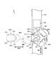
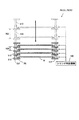
基板処理装置の一例として特許文献1の基板処理装置を説明する。図11は、特許文献1の基板処理装置を示す平面図である。図11に示すように、この基板処理装置900は、インデクサ910および処理モジュール920を備える。
The substrate processing apparatus of
インデクサ910は、直線的に延びるインデクサ搬送路911上を往復移動するインデクサロボット912と、インデクサ搬送路911に沿うように複数のキャリアCを載置可能なカセット載置部913とを備える。キャリアCには、複数の基板Wが収容される。
The
処理モジュール920は、インデクサ搬送路911に直交する主搬送路921上を往復移動する主搬送ロボット922と、主搬送路921を挟むように設けられる一対のユニット部930A,930Bとを備える。ユニット部930A,930Bには、基板Wに処理を行うための処理室933,934が設けられている。基板処理装置900において、基板Wは次のように搬送される。
The
まず、カセット載置部913に基板処理装置900の外部からキャリアCが搬入される。そして、キャリアCに収納された未処理の基板Wが、インデクサロボット912により取り出され、主搬送ロボット922に渡される。
First, the carrier C is carried into the
主搬送ロボット922に渡された基板Wは、処理室933,934に搬入され、洗浄処理が施される。その後、処理済の基板Wは、主搬送ロボット922およびインデクサロボット912により、再びキャリアC内に収納される。
上記の基板処理装置900において、インデクサロボット912は、キャリアCから未処理の基板Wを取り出すための基板取り出しアームと、キャリアCに処理済の基板Wを収納するための基板収納アームとを備える。
In the
例えばインデクサロボット912は、キャリアCから1枚の未処理の基板Wを取り出すとともに搬送し、その基板Wを主搬送ロボット922に受け渡す。また、インデクサロボット912は、主搬送ロボット922から1枚の処理済の基板Wを受け取るとともに搬送し、その基板WをキャリアC内に収納する。
For example, the
インデクサロボット912の動作時において、インデクサロボット912が取り出すべき未処理の基板Wが収納されているキャリアCと、インデクサロボット912が処理済の基板Wを収納するためのキャリアCとが異なる場合がある。
During the operation of the
この場合、インデクサロボット912は、例えば処理済の基板Wを1つのキャリアCに収納した後、未処理の基板Wが収納された他のキャリアCに向かってインデクサ搬送路911を移動しなければならない。これにより、基板処理装置900におけるスループットの向上が妨げられる。
In this case, the
そこで、基板処理装置900におけるスループットを向上させるために、インデクサロボット912の動作速度を高くすることが考えられる。しかしながら、インデクサロボット912の動作速度を著しく高くすることはできない。これは以下の理由による。
Therefore, in order to improve the throughput in the
キャリアCにおいて、より多くの基板Wを収容するために基板Wの収納間隔は非常に小さくなっている。これにより、インデクサロボット912の基板取り出しアームおよび基板収納アームはキャリアC内での基板Wの収納間隔に応じて肉厚が小さくなるように作製されている。そのため、基板取り出しアームおよび基板収納アームの剛性はさほど高くない。
In the carrier C, the accommodation interval of the substrates W is very small in order to accommodate more substrates W. As a result, the substrate take-out arm and the substrate storage arm of the
したがって、インデクサロボット912の動作速度を著しく高くすると、各アームに振動または変形等が発生する。その結果、基板Wの搬送不良が発生する。
Therefore, when the operation speed of the
本発明の目的は、基板の搬送時間を十分に短縮できる基板搬送装置、基板載置棚および基板処理装置を提供することである。 An object of the present invention is to provide a substrate transport apparatus, a substrate mounting shelf, and a substrate processing apparatus that can sufficiently shorten a substrate transport time.
(1)第1の発明に係る基板搬送装置は、基板が略水平姿勢で収納される複数段の収納溝を有する収納容器と、基板が略水平姿勢で載置される複数段の収納棚を有する基板載置棚との間で基板を搬送する基板搬送装置であって、互いに上下に設けられ、基板を略水平姿勢で保持する第1および第2の基板保持部と、収納容器および基板載置棚に対して基板の受け渡しを行うために第1および第2の基板保持部を移動させるとともに略水平方向に進退させる駆動機構と、第1および第2の基板保持部間の高さの差を調整する調整機構とを備え、調整機構は、収納容器と第1および第2の基板保持部との間での基板の受け渡しの際に、第1および第2の基板保持部間の高さの差を収納容器の収納溝間の高さの差に調整し、基板載置棚と第1および第2の基板保持部との間での基板の受け渡しの際に、第1および第2の基板保持部間の高さの差を基板載置棚の収納棚間の高さの差に調整するものである。 (1) A substrate transfer device according to a first aspect of the present invention includes a storage container having a plurality of storage grooves in which substrates are stored in a substantially horizontal posture, and a plurality of storage shelves in which substrates are placed in a substantially horizontal posture. A substrate transport apparatus for transporting a substrate to and from a substrate mounting shelf having first and second substrate holders that are provided one above the other and hold the substrate in a substantially horizontal posture, a storage container, and a substrate mounting A difference in height between the first and second substrate holders, and a drive mechanism that moves the first and second substrate holders and moves them back and forth in a substantially horizontal direction to transfer the substrates to the shelf. And an adjustment mechanism that adjusts the height between the first and second substrate holders when the substrate is transferred between the storage container and the first and second substrate holders. To the height difference between the storage grooves of the storage container, Adjusting the difference in height between the first and second substrate holders to the difference in height between the storage shelves of the substrate mounting shelf when transferring the substrate between the two substrate holders It is.
この発明に係る基板搬送装置は、互いに上下に設けられた第1および第2の基板保持部を用いて複数段の収納溝を有する収納容器との間で基板の受け渡しを行う。この基板の受け渡しが行われる際には、第1および第2の基板保持部間の高さの差が調整機構により収納容器の収納溝間の高さの差に調整される。 The substrate transfer apparatus according to the present invention transfers a substrate to and from a storage container having a plurality of storage grooves by using first and second substrate holders provided one above the other. When the substrate is transferred, the height difference between the first and second substrate holders is adjusted to the height difference between the storage grooves of the storage container by the adjusting mechanism.
これにより、第1および第2の基板保持部を、駆動機構により略水平方向に前進させることにより収納容器の2つの収納溝間にそれぞれ容易に挿入することができる。それにより、第1および第2の基板保持部と収納容器の収納溝との間で複数の基板の受け渡しが円滑に行われる。 Accordingly, the first and second substrate holding portions can be easily inserted between the two storage grooves of the storage container by being advanced in the substantially horizontal direction by the drive mechanism. Accordingly, the plurality of substrates are smoothly transferred between the first and second substrate holding portions and the storage groove of the storage container.
また、基板搬送装置は、第1および第2の基板保持部を用いて複数段の収納棚を有する基板載置棚との間で基板の受け渡しを行う。この受け渡しが行われる際には、第1および第2の基板保持部間の高さの差が調整機構により基板載置棚の収納棚間の高さの差に調整される。 In addition, the substrate transfer apparatus transfers the substrate to and from the substrate mounting shelf having a plurality of storage shelves using the first and second substrate holding units. When this delivery is performed, the height difference between the first and second substrate holders is adjusted to the height difference between the storage shelves of the substrate mounting shelf by the adjustment mechanism.
これにより、第1および第2の基板保持部を、駆動機構により略水平方向に前進させることにより基板載置棚の2つの収納棚間にそれぞれ容易に挿入することができる。それにより、第1および第2の基板保持部と基板載置棚の収納棚との間で複数の基板の受け渡しが円滑に行われる。 As a result, the first and second substrate holders can be easily inserted between the two storage shelves of the substrate mounting shelf by being advanced in the substantially horizontal direction by the drive mechanism. Accordingly, the plurality of substrates are smoothly transferred between the first and second substrate holding units and the storage shelf of the substrate mounting shelf.
このように、収納容器の収納溝間の高さの差と基板載置棚の収納棚間の高さの差とが異なる場合であっても、第1および第2の基板保持部は収納容器および基板載置棚に対して複数の基板を同時に受け渡しすることができる。その結果、基板の搬送時間が十分に短縮される。 As described above, even when the difference in height between the storage grooves of the storage container and the difference in height between the storage shelves of the substrate mounting shelf are different, the first and second substrate holders are stored in the storage container. A plurality of substrates can be delivered to the substrate mounting shelf at the same time. As a result, the substrate transfer time is sufficiently shortened.
(2)駆動機構は、収納容器および基板載置棚に対して基板の受け渡しを行うために第1および第2の基板保持部を略水平方向に個別に進退させてもよい。 (2) The drive mechanism may advance and retract the first and second substrate holders individually in a substantially horizontal direction in order to transfer the substrate to the storage container and the substrate mounting shelf.
この場合、第1および第2の基板保持部は略水平方向に個別に進退する。それにより、第1または第2の基板保持部と収納容器との間で1枚の基板の受け渡しを行うことが可能となる。また、第1または第2の基板保持部と基板収納棚との間で1枚の基板の受け渡しを行うことが可能となる。 In this case, the first and second substrate holders individually advance and retract in a substantially horizontal direction. Accordingly, it is possible to transfer one substrate between the first or second substrate holder and the storage container. In addition, it is possible to transfer one substrate between the first or second substrate holder and the substrate storage shelf.
(3)第2の発明に係る基板載置棚は、互いに上下に設けられた第1および第2の基板保持部を有する第1の基板搬送装置と互いに上下に設けられた第3および第4の基板保持部を有する第2の基板搬送装置との間で基板を受け渡すための基板載置棚であって、基板を略水平姿勢でそれぞれ支持する複数段の収納棚と、収納棚間の高さの差を調整する調整機構とを備え、調整機構は、第1の基板搬送装置との間での基板の受け渡しの際に、収納棚間の高さの差を第1および第2の基板保持部間の高さの差に調整し、第2の基板搬送装置との間での基板の受け渡しの際に、収納棚間の高さの差を第3および第4の基板保持部間の高さの差に調整するものである。 (3) A substrate mounting shelf according to a second aspect of the present invention includes a first substrate transport device having first and second substrate holders provided above and below and third and fourth provided above and below each other. A substrate mounting shelf for delivering a substrate to and from a second substrate transport apparatus having a substrate holding unit, and a plurality of storage shelves that respectively support the substrates in a substantially horizontal posture, and between the storage shelves An adjustment mechanism that adjusts the difference in height, and the adjustment mechanism is configured to adjust the difference in height between the storage shelves when the substrate is transferred to and from the first substrate transfer device. The height difference between the storage shelves is adjusted between the third and fourth substrate holders when the substrate is transferred to and from the second substrate transfer device. To adjust the difference in height.
この発明に係る基板載置棚においては、基板を略水平姿勢で支持する複数段の収納棚と第1の基板搬送装置との間で基板の受け渡しが行われる。 In the substrate mounting shelf according to the present invention, the substrate is transferred between a plurality of storage shelves that support the substrate in a substantially horizontal posture and the first substrate transport device.
この基板の受け渡しが行われる際には、収納棚間の高さの差が調整機構により第1および第2の基板保持部間の高さの差に調整される。これにより、第1および第2の基板保持部を2つの収納棚間にそれぞれ容易に挿入することができる。それにより、複数段の収納棚と第1の基板搬送装置との間で複数の基板の受け渡しが円滑に行われる。 When the substrate is transferred, the difference in height between the storage shelves is adjusted to the difference in height between the first and second substrate holders by the adjusting mechanism. Thereby, the first and second substrate holders can be easily inserted between the two storage shelves, respectively. Accordingly, the plurality of substrates are smoothly transferred between the plurality of storage shelves and the first substrate transport device.
また、この基板載置棚においては、収納棚と第2の搬送装置との間で基板の受け渡しが行われる。この基板の受け渡しが行われる際には、収納棚間の高さの差が調整機構により第3および第4の基板保持部間の高さの差に調整される。これにより、第3および第4の基板保持部を2つの収納棚間にそれぞれ容易に挿入することができる。それにより、複数段の収納棚と第2の基板搬送装置との間で複数の基板の受け渡しが円滑に行われる。 In the substrate mounting shelf, the substrate is transferred between the storage shelf and the second transport device. When the substrate is transferred, the height difference between the storage shelves is adjusted to the height difference between the third and fourth substrate holders by the adjusting mechanism. Thereby, the third and fourth substrate holders can be easily inserted between the two storage shelves, respectively. Accordingly, the plurality of substrates are smoothly transferred between the plurality of storage shelves and the second substrate transport apparatus.
このように、収納棚間の高さの差を調整機構により調整することができるので、第1の基板搬送装置の第1および第2の基板保持部間の高さの差と、第2の基板搬送装置の第3および第4の基板保持部間の高さの差とが異なる場合であっても、複数段の収納棚と第1および第2の基板搬送装置との間で複数の基板を同時に受け渡しすることができる。その結果、基板の搬送時間が十分に短縮される。 Thus, since the difference in height between the storage shelves can be adjusted by the adjustment mechanism, the difference in height between the first and second substrate holders of the first substrate transfer device, and the second Even if the difference in height between the third and fourth substrate holders of the substrate transfer device is different, a plurality of substrates between the plurality of storage shelves and the first and second substrate transfer devices Can be delivered at the same time. As a result, the substrate transfer time is sufficiently shortened.
(4)各段の収納棚は、略水平面内で所定の間隔をおいて配置される一組の棚部と、一組の棚部に設けられ、基板の下面を支持する複数の支持部材とを含んでもよい。 (4) Each stage of storage shelves has a set of shelves arranged at a predetermined interval in a substantially horizontal plane, and a plurality of support members provided on the set of shelves and supporting the lower surface of the substrate. May be included.
この場合、各段の収納棚の棚部の間に空間が形成される。これにより、複数段の収納棚と第1の基板搬送装置との間で基板の受け渡しが行われる際に、棚部の間に形成される空間に第1および第2の基板保持部をより容易に挿入することができる。 In this case, a space is formed between the shelves of the storage shelves at each stage. This makes it easier to place the first and second substrate holding portions in the space formed between the shelf portions when the substrates are transferred between the plurality of storage shelves and the first substrate transfer device. Can be inserted into.
また、複数段の収納棚と第2の基板搬送装置との間で基板の受け渡しが行われる際に、棚部の間に形成される空間に第3および第4の基板保持部をより容易に挿入することができる。 In addition, when the substrates are transferred between the plurality of storage shelves and the second substrate transport device, the third and fourth substrate holders are more easily placed in the space formed between the shelves. Can be inserted.
それにより、複数段の収納棚と第1の基板搬送装置との間、および複数段の収納棚と第2の基板搬送装置との間で複数の基板の受け渡しがより円滑に行われる。 Thereby, the delivery of the plurality of substrates is performed more smoothly between the plurality of storage shelves and the first substrate transfer device and between the plurality of storage shelves and the second substrate transfer device.
(5)第3の発明に係る基板処理装置は、基板に処理を行う基板処理装置であって、基板を処理する処理領域と、処理領域に対して基板を搬入および搬出する搬入搬出領域と、処理領域と搬入搬出領域との間で基板を受け渡す受け渡し部とを備え、搬入搬出領域は、基板が略水平姿勢で収納される複数段の収納溝を有する収納容器が載置される容器載置部と、容器載置部に載置された収納容器と受け渡し部との間で基板を搬送する第1の基板搬送装置とを含み、処理領域は、基板に処理を行う処理部と、受け渡し部と処理部との間で基板を搬送する第2の基板搬送装置とを含み、受け渡し部は、基板が略水平姿勢で載置される複数段の収納棚を有する基板載置棚を含み、第1の基板搬送装置は、互いに上下に設けられ、基板を略水平姿勢で保持する第1および第2の基板保持部と、収納容器および基板載置棚に対して基板の受け渡しを行うために第1および第2の基板保持部を移動させるとともに略水平方向に進退させる駆動機構と、第1および第2の基板保持部間の高さの差を調整する調整機構とを備え、調整機構は、収納容器と第1および第2の基板保持部との間での基板の受け渡しの際に、第1および第2の基板保持部間の高さの差を収納容器の収納溝間の高さの差に調整し、基板載置棚と第1および第2の基板保持部との間での基板の受け渡しの際に、第1および第2の基板保持部間の高さの差を基板載置棚の収納棚間の高さの差に調整するものである。 (5) A substrate processing apparatus according to a third invention is a substrate processing apparatus for processing a substrate, a processing region for processing a substrate, a loading / unloading region for loading and unloading a substrate with respect to the processing region, A transfer section that transfers the substrate between the processing area and the carry-in / out area, and the carry-in / out area is a container mounting on which a storage container having a plurality of storage grooves in which the substrate is stored in a substantially horizontal posture is placed. And a first substrate transport apparatus that transports the substrate between the storage container placed on the container placement unit and the transfer unit, and the processing region includes a processing unit that processes the substrate, and a transfer A second substrate transport device that transports the substrate between the processing unit and the processing unit, the transfer unit includes a substrate mounting shelf having a plurality of storage shelves on which the substrate is mounted in a substantially horizontal posture, The first substrate transfer device is provided one above the other and holds the substrate in a substantially horizontal posture. First and second substrate holders, and a drive mechanism for moving the first and second substrate holders and transferring them back and forth in a substantially horizontal direction to transfer the substrates to the storage container and the substrate mounting shelf. And an adjustment mechanism that adjusts the difference in height between the first and second substrate holders, and the adjustment mechanism delivers the substrate between the storage container and the first and second substrate holders. In this case, the height difference between the first and second substrate holders is adjusted to the height difference between the storage grooves of the storage container, and the substrate mounting shelf, the first and second substrate holders, When the substrate is transferred between the first and second substrates, the difference in height between the first and second substrate holders is adjusted to the difference in height between the storage shelves of the substrate mounting shelf.
この発明に係る基板処理装置において、搬入搬出領域の容器載置部には収納容器が載置される。収納容器の複数の収納溝には基板が略水平姿勢で収納される。搬入搬出領域の第1の基板搬送装置は、容器載置部上の収納容器と受け渡し部の基板載置棚との間で基板を搬送する。基板載置棚の複数段の収納棚には基板が略水平姿勢で載置される。 In the substrate processing apparatus according to the present invention, the storage container is placed on the container placement section in the carry-in / out area. The substrate is stored in a substantially horizontal posture in the plurality of storage grooves of the storage container. The first substrate transport device in the carry-in / out region transports the substrate between the storage container on the container placement unit and the substrate placement shelf of the delivery unit. Substrates are placed in a substantially horizontal posture on a plurality of storage shelves of the substrate placement shelf.
処理領域の第2の基板搬送装置は、受け渡し部の基板載置棚と処理部との間で基板を搬送する。これにより、搬入搬出領域において収納容器に収納された基板が、第1および第2の基板搬送装置により処理部に搬送され、処理される。また、処理部で処理された基板が第2および第1の基板搬送装置により搬入搬出領域の収納容器に搬送され、収納される。 The second substrate transport device in the processing region transports the substrate between the substrate mounting shelf of the transfer unit and the processing unit. Thereby, the board | substrate accommodated in the storage container in the carrying in / out area | region is conveyed by the process part by the 1st and 2nd board | substrate conveyance apparatus, and is processed. In addition, the substrate processed in the processing unit is transported and stored in the storage container in the loading / unloading region by the second and first substrate transport apparatuses.
第1の基板搬送装置は、互いに上下に設けられた第1および第2の基板保持部を用いて複数段の収納溝を有する収納容器との間で基板の受け渡しを行う。この基板の受け渡しが行われる際には、第1および第2の基板保持部間の高さの差が調整機構により収納容器の収納溝間の高さの差に調整される。 The first substrate transfer device transfers a substrate to and from a storage container having a plurality of storage grooves using first and second substrate holders provided one above the other. When the substrate is transferred, the height difference between the first and second substrate holders is adjusted to the height difference between the storage grooves of the storage container by the adjusting mechanism.
これにより、第1および第2の基板保持部を、駆動機構により略水平方向に前進させることにより収納容器の収納溝間にそれぞれ容易に挿入することができる。それにより、第1および第2の基板保持部と収納容器の収納溝との間で複数の基板の受け渡しが円滑に行われる。 Accordingly, the first and second substrate holding portions can be easily inserted between the storage grooves of the storage container by being advanced in the substantially horizontal direction by the drive mechanism. Accordingly, the plurality of substrates are smoothly transferred between the first and second substrate holding portions and the storage groove of the storage container.
また、第1の基板搬送装置は、第1および第2の基板保持部を用いて複数段の収納棚を有する基板載置棚の間で基板の受け渡しを行う。この受け渡しが行われる際には、第1および第2の基板保持部間の高さの差が調整機構により基板載置棚の収納棚間の高さの差に調整される。 In addition, the first substrate transport apparatus transfers substrates between substrate mounting shelves having a plurality of storage shelves using the first and second substrate holding units. When this delivery is performed, the height difference between the first and second substrate holders is adjusted to the height difference between the storage shelves of the substrate mounting shelf by the adjustment mechanism.
これにより、第1および第2の基板保持部を駆動機構により略水平方向に前進させることにより基板載置棚の2つの収納棚間にそれぞれ容易に挿入することができる。それにより、第1および第2の基板保持部と基板載置棚の収納棚との間で複数の基板の受け渡しが円滑に行われる。 Accordingly, the first and second substrate holders can be easily inserted between the two storage shelves of the substrate mounting shelf by advancing in a substantially horizontal direction by the drive mechanism. Accordingly, the plurality of substrates are smoothly transferred between the first and second substrate holding units and the storage shelf of the substrate mounting shelf.
このように、収納容器の収納溝間の高さの差と基板載置棚の収納棚間の高さの差とが異なる場合であっても、第1の基板搬送装置の第1および第2の基板保持部は、収納容器および基板載置棚に対して複数の基板を同時に受け渡しすることができる。その結果、基板の搬送時間が十分に短縮され、基板処理におけるスループットが十分に向上する。 Thus, even if the difference in height between the storage grooves of the storage container and the difference in height between the storage shelves of the substrate mounting shelf are different, the first and second of the first substrate transport device The substrate holding unit can simultaneously transfer a plurality of substrates to the storage container and the substrate mounting shelf. As a result, the substrate transfer time is sufficiently shortened, and the throughput in substrate processing is sufficiently improved.
(6)処理部は、基板を洗浄する洗浄処理部を含んでもよい。この場合、基板が洗浄処理部により洗浄される。 (6) The processing unit may include a cleaning processing unit that cleans the substrate. In this case, the substrate is cleaned by the cleaning processing unit.
(7)第4の発明に係る基板処理装置は、基板に処理を行う基板処理装置であって、基板を処理する処理領域と、処理領域に対して基板を搬入および搬出する搬入搬出領域と、処理領域と搬入搬出領域との間で基板を受け渡す受け渡し部とを備え、搬入搬出領域は、基板が略水平姿勢で収納される複数段の収納溝を有する収納容器が載置される容器載置部と、互いに上下に設けられた第1および第2の基板保持部を有し、容器載置部に載置された収納容器と受け渡し部との間で基板を搬送する第1の基板搬送装置とを含み、処理領域は、基板に処理を行う処理部と、互いに上下に設けられた第3および第4の基板保持部を有し、受け渡し部と処理部との間で基板を搬送する第2の基板搬送装置とを含み、受け渡し部は、基板が略水平姿勢で載置される複数段の収納棚を有する基板載置棚を含み、基板載置棚は、基板を略水平姿勢でそれぞれ支持する複数段の収納棚と、収納棚間の高さの差を調整する調整機構とを備え、調整機構は、第1の基板搬送装置との間での基板の受け渡しの際に、収納棚間の高さの差を第1および第2の基板保持部間の高さの差に調整し、第2の基板搬送装置との間での基板の受け渡しの際に、収納棚間の高さの差を第3および第4の基板保持部間の高さの差に調整するものである。 (7) A substrate processing apparatus according to a fourth invention is a substrate processing apparatus for processing a substrate, a processing region for processing a substrate, a loading / unloading region for loading and unloading a substrate with respect to the processing region, A transfer section that transfers the substrate between the processing area and the carry-in / out area, and the carry-in / out area is a container mounting on which a storage container having a plurality of storage grooves in which the substrate is stored in a substantially horizontal posture is placed. A first substrate transport unit having a mounting unit and first and second substrate holding units provided above and below each other, and transporting the substrate between the storage container mounted on the container mounting unit and the transfer unit The processing area includes a processing unit that processes a substrate and third and fourth substrate holding units provided above and below, and transports the substrate between the transfer unit and the processing unit. Including a second substrate transfer device, and the transfer unit has the substrate mounted in a substantially horizontal posture. The substrate mounting shelf includes a plurality of storage shelves, and the substrate mounting shelf adjusts a difference in height between the storage shelves and a plurality of storage shelves that respectively support the substrates in a substantially horizontal posture. A mechanism for adjusting the height difference between the first and second substrate holders when the substrate is transferred to and from the first substrate transfer device. The height difference between the storage shelves is adjusted to the height difference between the third and fourth substrate holders when the substrate is transferred to and from the second substrate transfer device. Is.
この発明に係る基板処理装置において、搬入搬出領域の容器載置部には収納容器が載置される。収納容器の複数の収納溝には基板が略水平姿勢で収納される。搬入搬出領域の第1の基板搬送装置は、容器載置部上の収納容器と受け渡し部の基板載置棚との間で基板を搬送する。基板載置棚の複数段の収納棚には基板が略水平姿勢で載置される。 In the substrate processing apparatus according to the present invention, the storage container is placed on the container placement section in the carry-in / out area. The substrate is stored in a substantially horizontal posture in the plurality of storage grooves of the storage container. The first substrate transport device in the carry-in / out region transports the substrate between the storage container on the container placement unit and the substrate placement shelf of the delivery unit. Substrates are placed in a substantially horizontal posture on a plurality of storage shelves of the substrate placement shelf.
処理領域の第2の基板搬送装置は、受け渡し部の基板載置棚と処理部との間で基板を搬送する。これにより、搬入搬出領域において収納容器に収納された基板が、第1および第2の基板搬送装置により処理部に搬送され、処理される。また、処理部で処理された基板が第2および第1の基板搬送装置により搬入搬出領域の収納容器に搬送され、収納される。 The second substrate transport device in the processing region transports the substrate between the substrate mounting shelf of the transfer unit and the processing unit. Thereby, the board | substrate accommodated in the storage container in the carrying in / out area | region is conveyed by the process part by the 1st and 2nd board | substrate conveyance apparatus, and is processed. In addition, the substrate processed in the processing unit is transported and stored in the storage container in the loading / unloading region by the second and first substrate transport apparatuses.
第1の基板搬送装置は、互いに上下に設けられた第1および第2の基板保持部を用いて複数段の収納棚を有する基板載置棚との間で基板の受け渡しを行う。この基板の受け渡しが行われる際には、収納棚間の高さの差が調整機構により第1および第2の基板保持部間の高さの差に調整される。これにより、第1および第2の基板保持部を2つの収納棚間にそれぞれ容易に挿入することができる。それにより、複数段の収納棚と第1の基板搬送装置との間で複数の基板の受け渡しが円滑に行われる。 The first substrate transport apparatus transfers substrates to and from a substrate mounting shelf having a plurality of storage shelves using first and second substrate holders provided one above the other. When the substrate is transferred, the difference in height between the storage shelves is adjusted to the difference in height between the first and second substrate holders by the adjusting mechanism. Thereby, the first and second substrate holders can be easily inserted between the two storage shelves, respectively. Accordingly, the plurality of substrates are smoothly transferred between the plurality of storage shelves and the first substrate transport device.
また、第2の基板搬送装置は、互いに上下に設けられた第3および第4の基板保持部を用いて複数段の収納棚を有する基板載置棚との間で基板の受け渡しを行う。この基板の受け渡しが行われる際には、収納棚間の高さの差が調整機構により第3および第4の基板保持部間の高さの差に調整される。これにより、第3および第4の基板保持部を2つの収納棚の間にそれぞれ容易に挿入することができる。それにより、複数段の収納棚と第2の基板搬送装置との間で複数の基板の受け渡しが円滑に行われる。 In addition, the second substrate transfer apparatus transfers the substrate to and from the substrate mounting shelf having a plurality of storage shelves using the third and fourth substrate holding units provided above and below each other. When the substrate is transferred, the height difference between the storage shelves is adjusted to the height difference between the third and fourth substrate holders by the adjusting mechanism. Thereby, the third and fourth substrate holders can be easily inserted between the two storage shelves, respectively. Accordingly, the plurality of substrates are smoothly transferred between the plurality of storage shelves and the second substrate transport apparatus.
このように、収納棚間の高さの差を調整機構により調整することができるので、第1の基板搬送装置の第1および第2の基板保持部間の高さの差と、第2の基板搬送装置の第3および第4の基板保持部間の高さの差とが異なる場合であっても、複数段の収納棚と第1および第2の基板搬送装置との間で複数の基板を同時に受け渡しすることができる。その結果、基板の搬送時間が十分に短縮され、基板処理におけるスループットが十分に向上する。 Thus, since the difference in height between the storage shelves can be adjusted by the adjustment mechanism, the difference in height between the first and second substrate holders of the first substrate transfer device, and the second Even if the difference in height between the third and fourth substrate holders of the substrate transfer device is different, a plurality of substrates between the plurality of storage shelves and the first and second substrate transfer devices Can be delivered at the same time. As a result, the substrate transfer time is sufficiently shortened, and the throughput in substrate processing is sufficiently improved.
(8)処理部は、基板を洗浄する洗浄処理部を含んでもよい。この場合、基板が洗浄処理部により洗浄される。 (8) The processing unit may include a cleaning processing unit that cleans the substrate. In this case, the substrate is cleaned by the cleaning processing unit.
本発明によれば、複数の基板を同時に搬送することが可能となり、基板の搬送時間が十分に短縮できる。 According to the present invention, a plurality of substrates can be transferred simultaneously, and the substrate transfer time can be sufficiently shortened.
本発明の一実施の形態に係る基板搬送装置、基板載置棚および基板処理装置について説明する。以下の説明において、基板とは、半導体ウェハ、フォトマスク用ガラス基板、液晶表示装置用ガラス基板、プラズマディスプレイ用ガラス基板、光ディスク用基板、磁気ディスク用基板、光磁気ディスク用基板等をいう。 A substrate transfer device, a substrate mounting shelf, and a substrate processing apparatus according to an embodiment of the present invention will be described. In the following description, the substrate refers to a semiconductor wafer, a glass substrate for a photomask, a glass substrate for a liquid crystal display device, a glass substrate for a plasma display, an optical disk substrate, a magnetic disk substrate, a magneto-optical disk substrate, and the like.
[1]第1の実施の形態
(1)基板処理装置の構成
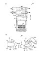
図1(a)は本発明の第1の実施の形態に係る基板処理装置の平面図であり、図1(b)は図1(a)の基板処理装置を矢印Xの方向から見た模式的側面図である。また、図2は、図1(a)のA−A線断面を模式的に示す図である。
[1] First Embodiment (1) Configuration of Substrate Processing Apparatus FIG. 1A is a plan view of a substrate processing apparatus according to a first embodiment of the present invention, and FIG. 2 is a schematic side view of the substrate processing apparatus 1 (a) as viewed from the direction of an arrow X. FIG. Moreover, FIG. 2 is a figure which shows typically the AA line cross section of Fig.1 (a).
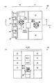
図1(a)に示すように、基板処理装置100は、インデクサブロック10および処理ブロック11を有する。インデクサブロック10および処理ブロック11は、互いに並列に設けられている。
As shown in FIG. 1A, the
インデクサブロック10には、複数のキャリア載置台40、インデクサロボットIRおよび制御部4が設けられている。各キャリア載置台40上には、複数枚の基板Wを多段に収納するキャリアCが載置される。キャリアCの詳細については後述する。
The
インデクサロボットIRは、矢印U(図1(a))の方向に移動可能で鉛直軸の周りで回転可能かつ上下方向に昇降可能に構成されている。インデクサロボットIRには、基板Wを受け渡すためのハンドIRH1,IRH2が上下に設けられている。ハンドIRH1,IRH2は、基板Wの下面の周縁部および外周端部を保持する。インデクサロボットIRの詳細については後述する。 The indexer robot IR is configured to be movable in the direction of an arrow U (FIG. 1A), to be rotatable about a vertical axis, and to be vertically movable. In the indexer robot IR, hands IRH1 and IRH2 for delivering the substrate W are provided above and below. The hands IRH1 and IRH2 hold the peripheral edge and the outer peripheral edge of the lower surface of the substrate W. Details of the indexer robot IR will be described later.
制御部4は、CPU(中央演算処理装置)を含むコンピュータ等からなり、基板処理装置100内の各部を制御する。
The
図1(b)に示すように、処理ブロック11には、複数の表面洗浄ユニットSSおよびメインロボットMRが設けられている。本例では、4つの表面洗浄ユニットSSが処理ブロック11の一方の側面側に上下に積層配置されており、他の4つの表面洗浄ユニットSSが処理ブロック11の他方の側面側に上下に積層配置されている。
As shown in FIG. 1B, the
メインロボットMRは、処理ブロック11の一方の側面側に位置する複数の表面洗浄ユニットSSと、処理ブロック11の他方の側面側に位置する複数の表面洗浄ユニットSSとの間に設けられている。メインロボットMRは、鉛直軸の周りで回転可能でかつ上下方向に昇降可能に構成されている。
The main robot MR is provided between the plurality of surface cleaning units SS located on one side surface of the
また、メインロボットMRには、基板Wを受け渡すためのハンドMRH1,MRH2が上下に設けられている。ハンドMRH1,MRH2は基板Wの下面の周縁部および外周端部を保持する。メインロボットMRの詳細については後述する。 The main robot MR is provided with hands MRH1 and MRH2 for delivering the substrate W up and down. The hands MRH1 and MRH2 hold the peripheral edge and the outer peripheral edge of the lower surface of the substrate W. Details of the main robot MR will be described later.
図2に示すように、インデクサブロック10と処理ブロック11との間には、インデクサロボットIRとメインロボットMRとの間で基板Wの受け渡しを行うための基板載置部PASS1,PASS2が上下に設けられている。
As shown in FIG. 2, between the
基板載置部PASS1,PASS2は、ともに複数枚の基板Wを多段に載置することができる。上側の基板載置部PASS1は、基板Wを処理ブロック11からインデクサブロック10へ搬送する際に用いられ、下側の基板載置部PASS2は、基板Wをインデクサブロック10から処理ブロック11へ搬送する際に用いられる。基板載置部PASS1,PASS2の詳細については後述する。
The substrate platforms PASS1, PASS2 can both mount a plurality of substrates W in multiple stages. The upper substrate platform PASS1 is used when transporting the substrate W from the
(2)基板処理装置の動作の概要
次に、図1および図2を参照して基板処理装置100の動作の概要について説明する。なお、以下に説明する基板処理装置100の各構成要素の動作は、図1の制御部4により制御される。
(2) Outline of Operation of Substrate Processing Apparatus Next, an outline of the operation of the
まず、インデクサロボットIRは、キャリア載置台40上に載置されたキャリアCの1つから上下に設けられた2つのハンドIRH1,IRH2を用いて2枚の未処理の基板Wを取り出す。インデクサロボットIRは、矢印Uの方向に移動しつつ鉛直軸の周りで回転し、2枚の未処理の基板Wを基板載置部PASS2に載置する。 First, the indexer robot IR takes out two unprocessed substrates W from one of the carriers C mounted on the carrier mounting table 40 using the two hands IRH1 and IRH2 provided above and below. The indexer robot IR rotates around the vertical axis while moving in the direction of the arrow U, and places two unprocessed substrates W on the substrate platform PASS2.
メインロボットMRは、鉛直軸の周りで回転しつつ昇降し、下側のハンドMRH2を用いて基板載置部PASS2から基板Wを受け取る。次に、メインロボットMRは、上側のハンドMRH1により表面洗浄ユニットSSのいずれかから表面洗浄処理後の基板Wを取り出し、その表面洗浄ユニットSSにハンドMRH2に保持する基板Wを搬入する。そして、メインロボットMRは、再び鉛直軸の周りで回転しつつ昇降し、上側のハンドMRH1に保持する基板Wを基板載置部PASS1に載置する。 The main robot MR moves up and down while rotating around the vertical axis, and receives the substrate W from the substrate platform PASS2 using the lower hand MRH2. Next, the main robot MR takes out the substrate W after the surface cleaning process from any of the surface cleaning units SS by the upper hand MRH1, and carries the substrate W held by the hand MRH2 into the surface cleaning unit SS. Then, the main robot MR moves up and down again while rotating around the vertical axis, and places the substrate W held by the upper hand MRH1 on the substrate platform PASS1.
インデクサロボットIRは、基板載置部PASS2から2つのハンドIRH1,IRH2を用いて2枚の処理済の基板Wを取り出す。インデクサロボットIRは、矢印Uの方向に移動しつつ鉛直軸の周りで回転し、2枚の処理済の基板Wをキャリア載置台40上に載置されたキャリアCの1つに収納する。 The indexer robot IR takes out two processed substrates W from the substrate platform PASS2 using the two hands IRH1 and IRH2. The indexer robot IR rotates around the vertical axis while moving in the direction of the arrow U, and stores the two processed substrates W in one of the carriers C mounted on the carrier mounting table 40.
本実施の形態に係る基板処理装置100においては、このようなインデクサロボットIRおよびメインロボットMRによる基板Wの搬送動作が連続的に繰り返される。
In the
(3)キャリアおよび基板載置部の構成
図3は図1のキャリアCおよび基板載置部PASS1,PASS2の構造を説明するための縦断面図である。
(3) Configuration of Carrier and Substrate Placement Section FIG. 3 is a longitudinal sectional view for explaining the structure of the carrier C and the substrate placement sections PASS1, PASS2 in FIG.
図3(a)に図1のキャリアCの縦断面図が示されている。図3(a)に示すように、キャリアCは箱型形状を有し、一面が開口している(開口部C1)。 FIG. 3A shows a longitudinal sectional view of the carrier C in FIG. As shown in FIG. 3A, the carrier C has a box shape, and one surface is open (opening C1).
鉛直方向に延びるキャリアCの内面には、水平方向に沿って延びる複数の基板収納溝C2が形成されている。 A plurality of substrate storage grooves C2 extending along the horizontal direction are formed on the inner surface of the carrier C extending in the vertical direction.
各基板収納溝C2には、基板Wが一枚ずつ収納される。上下に隣接する基板収納溝C2間の間隔GAは、例えば10mm程度に設定される。この場合、キャリアC内には、基板Wが約10mmの間隔で収納される。基板収納溝C2間の間隔GAを小さくすることにより、キャリアCは多数の基板Wを収納することができる。 One substrate W is stored in each substrate storage groove C2. The gap GA between the substrate storage grooves C2 adjacent in the vertical direction is set to about 10 mm, for example. In this case, the substrates W are accommodated in the carrier C at intervals of about 10 mm. By reducing the gap GA between the substrate storage grooves C2, the carrier C can store a large number of substrates W.
図3(b)に図1の基板載置部PASS1,PASS2の縦断面図が示されている。図3(b)に示すように、基板載置部PASS1,PASS2は、複数の支持板51が複数の支持柱52により多段に積層された構造を有する。
FIG. 3B shows a longitudinal sectional view of the substrate platforms PASS1, PASS2 of FIG. As shown in FIG. 3B, the substrate platforms PASS <b> 1 and PASS <b> 2 have a structure in which a plurality of
支持板51上には、基板Wの下面を支持する複数の支持ピンPNが設けられている。インデクサロボットIRとメインロボットMRとの間で基板Wの受け渡しが行われる際には、基板Wが一時的に基板載置部PASS1,PASS2の支持ピンPN上に載置される。この基板載置部PASS1,PASS2において、上下に隣接する支持板51間の間隔GCは、例えば45mm程度である。この場合、基板載置部PASS1,PASS2では基板Wが約45mmの間隔で載置される。
A plurality of support pins PN that support the lower surface of the substrate W are provided on the
本実施の形態において、基板載置部PASS1,PASS2の上下に隣接する支持板51間の間隔GCは、キャリアCの基板収納溝C2間の間隔GAよりも大きく設定されている。
In the present embodiment, the interval GC between the
基板載置部PASS1,PASS2には、各支持板51ごとに基板Wの有無を検出する光学式のセンサ(図示せず)が設けられている。それにより、基板載置部PASS1,PASS2において基板Wが載置されているか否かの判定を行うことが可能となる。
The substrate platforms PASS1, PASS2 are provided with optical sensors (not shown) that detect the presence or absence of the substrate W for each
(4)インデクサロボットの構成
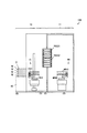
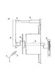
続いて、インデクサロボットIRの詳細な構成について説明する。図4はインデクサロボットIRの側面図であり、図5はインデクサロボットIRの平面図である。
(4) Configuration of Indexer Robot Subsequently, a detailed configuration of the indexer robot IR will be described. FIG. 4 is a side view of the indexer robot IR, and FIG. 5 is a plan view of the indexer robot IR.
図4および図5に示すように、インデクサロボットIRは搬送レール部210、移動支持柱220、昇降支持部230およびベース部240を備える。
As shown in FIGS. 4 and 5, the indexer robot IR includes a
搬送レール部210は、インデクサブロック10の床面に取り付けられている。搬送レール部210上に、鉛直方向に延びる移動支持柱220が取り付けられている。移動支持柱220には、水平方向に延びる昇降支持部230の一端が取り付けられている。昇降支持部230の他端にベース部240が取り付けられている。
The
水平方向に延びる搬送レール部210には、例えばボールねじおよびモータ等からなる水平移動機構211が設けられている。水平移動機構211により、移動支持柱220は搬送レール部210に沿って水平方向に移動する(矢印MV1)。
A
移動支持柱220には、例えばボールねじおよびモータ等からなる鉛直移動機構221が設けられている。鉛直移動機構221により、昇降支持部230は移動支持柱220に沿って鉛直方向に移動する(矢印MV2)。これにより、ベース部240は、水平方向および鉛直方向に移動可能となっている。
The moving
ベース部240上には、回転ステージ250がベース部240に対して回転可能に設けられている。回転ステージ250は、ベース部240の内部に設けられた回転機構241により回転する(矢印MV3)。回転機構241は、例えばモータにより構成される。
A
回転ステージ250には昇降軸260が立設されている。また、回転ステージ250上には、多関節型アームIAM1を介してハンドIRH1が接続され、昇降軸260および多関節型アームIAM2を介してハンドIRH2が接続されている。
A
多関節型アームIAM1,IAM2は、図示しない駆動機構によりそれぞれ独立に駆動され、ハンドIRH1,IRH2をそれぞれ一定姿勢に維持しつつ水平方向に進退させる(矢印MV4)。 The articulated arms IAM1 and IAM2 are independently driven by a driving mechanism (not shown), and move the hands IRH1 and IRH2 in the horizontal direction while maintaining the hands in a fixed posture (arrow MV4).
ハンドIRH1は、回転ステージ250に対して一定の高さに設けられており、ハンドIRH1はハンドIRH2よりも上方に位置している。
The hand IRH1 is provided at a certain height with respect to the
昇降軸260の内部には、ボールねじ261が設けられている。ボールねじ261は回転ステージ250の内部に設けられたモータ251に接続されている。モータ251が動作することによりボールねじ261が回転し、昇降軸260に取り付けられた多関節型アームIAM2が鉛直方向に移動する(矢印MV5)。
A
これにより、ハンドIRH1とハンドIRH2との高さの差が所定の範囲内で変化する。図4の例では、多関節型アームIAM2が昇降軸260の最も高い位置に移動した場合のハンドIRH1とハンドIRH2との高さの差が矢印HG1で示されている。また、多関節型アームIAM2が昇降軸260の最も低い位置に移動した場合のハンドIRH1とハンドIRH2との高さの差が矢印HG2で示されている。
Thereby, the difference in height between the hand IRH1 and the hand IRH2 changes within a predetermined range. In the example of FIG. 4, the difference in height between the hand IRH1 and the hand IRH2 when the articulated arm IAM2 moves to the highest position of the lifting
矢印HG1で示されるハンドIRH1とハンドIRH2との高さの差は、例えば図3(a)のキャリアCの基板収納溝C2間の間隔GAと等しくなるように設定され、矢印HG2で示されるハンドIRH1とハンドIRH2との高さの差は、例えば図3(b)の基板載置部PASS1,PASS2の支持板51間の間隔GCと等しくなるように設定される。
The difference in height between the hand IRH1 and the hand IRH2 indicated by the arrow HG1 is set to be equal to the distance GA between the substrate storage grooves C2 of the carrier C in FIG. 3A, for example, and the hand indicated by the arrow HG2 The difference in height between the IRH1 and the hand IRH2 is set to be equal to, for example, the interval GC between the
図5に示すように、ハンドIRH1,IRH2は互いに同じ形状を有し、それぞれ略U字状に形成されている。ハンドIRH1はほぼ平行に延びる2本の爪部IH11を有し、ハンドIRH2はほぼ平行に延びる2本の爪部IH12を有する。 As shown in FIG. 5, the hands IRH1 and IRH2 have the same shape and are formed in a substantially U shape. The hand IRH1 has two claw portions IH11 extending substantially in parallel, and the hand IRH2 has two claw portions IH12 extending substantially in parallel.
また、ハンドIRH1,IRH2上には、それぞれ複数の支持ピン271が取り付けられている。本実施の形態では、ハンドIRH1,IRH2の上面に載置される基板Wの外周に沿ってほぼ均等にそれぞれ4個の支持ピン271が取り付けられている。この4個の支持ピン271により基板Wの下面の周縁部および外周端部が保持される。
A plurality of support pins 271 are attached to the hands IRH1 and IRH2, respectively. In the present embodiment, four
ハンドIRH1,IRH2は、例えば4mm程度の厚みを有する。これにより、ハンドIRH1,IRH2は、図3(a)のキャリアCに収納された複数の基板W間に挿入可能となっている。 The hands IRH1 and IRH2 have a thickness of about 4 mm, for example. Accordingly, the hands IRH1 and IRH2 can be inserted between the plurality of substrates W accommodated in the carrier C in FIG.
上記の水平移動機構211、鉛直移動機構221、回転機構241およびモータ251の動作は図1の制御部4により制御される。
The operations of the
(5)メインロボットの構成
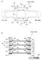
次に、メインロボットMRの詳細な構成について説明する。図6(a)は、メインロボットMRの側面図であり、図6(b)はメインロボットMRの平面図である。
(5) Configuration of Main Robot Next, a detailed configuration of the main robot MR will be described. FIG. 6A is a side view of the main robot MR, and FIG. 6B is a plan view of the main robot MR.
図6(a)および図6(b)に示すように、メインロボットMRはベース部21を備え、ベース部21に対して昇降可能かつ回転可能に昇降回転部22が設けられている。昇降回転部22には、多関節型アームAM1を介してハンドMRH1が接続され、多関節型アームAM2を介してハンドMRH2が接続されている。
As shown in FIGS. 6A and 6B, the main robot MR includes a
昇降回転部22は、ベース部21内に設けられた昇降駆動機構25により上下方向に昇降されるとともに、ベース部21内に設けられた回転駆動機構26により鉛直軸の周りで回転される。
The up-and-
多関節型アームAM1,AM2は、それぞれ図示しない駆動機構により独立に駆動され、ハンドMRH1,MRH2をそれぞれ一定姿勢に維持しつつ水平方向に進退させる。 The articulated arms AM1 and AM2 are independently driven by a driving mechanism (not shown), and advance and retreat in the horizontal direction while maintaining the hands MRH1 and MRH2 in a fixed posture.
ハンドMRH1,MRH2は、それぞれ昇降回転部22に対して一定の高さに設けられており、ハンドMRH1はハンドMRH2よりも上方に位置している。ハンドMRH1とハンドMRH2との高さの差M1(図6(a))は一定に維持される。
The hands MRH1 and MRH2 are provided at a certain height with respect to the lifting / lowering rotating
なお、ハンドMRH1とハンドMRH2との高さの差M1は、例えば図3(b)に示される基板載置部PASS1,PASS2の上下に隣接する支持板51間の間隔GCとほぼ等しくなるように設定されてもよい。
The height difference M1 between the hand MRH1 and the hand MRH2 is, for example, substantially equal to the interval GC between the
ハンドMRH1,MRH2は互いに同じ形状を有し、それぞれ略U字状に形成されている。ハンドMRH1はほぼ平行に延びる2本の爪部H11を有し、ハンドMRH2はほぼ平行に延びる2本の爪部H12を有する。また、ハンドMRH1,MRH2上には、それぞれ複数の支持ピン23が取り付けられている。 The hands MRH1 and MRH2 have the same shape, and are each formed in a substantially U shape. The hand MRH1 has two claw portions H11 extending substantially in parallel, and the hand MRH2 has two claw portions H12 extending substantially in parallel. A plurality of support pins 23 are attached to the hands MRH1 and MRH2.
本実施の形態では、ハンドMRH1,MRH2の上面に載置される基板Wの外周に沿ってほぼ均等にそれぞれ4個の支持ピン23が取り付けられている。この4個の支持ピン23により基板Wの下面の周縁部および外周端部が保持される。
In the present embodiment, four support pins 23 are attached almost evenly along the outer periphery of the substrate W placed on the upper surfaces of the hands MRH1 and MRH2. The four
ハンドMRH1,MRH2は、インデクサロボットIRのハンドIRH1,IRH2よりも厚く形成され、例えば7mm程度の厚みを有する。これにより、ハンドMRH1,MRH2は、インデクサロボットIRのハンドIRH1,IRH2に比べて高い剛性を有する。 The hands MRH1 and MRH2 are formed thicker than the hands IRH1 and IRH2 of the indexer robot IR, and have a thickness of about 7 mm, for example. Thereby, the hands MRH1 and MRH2 have higher rigidity than the hands IRH1 and IRH2 of the indexer robot IR.
また、図3(b)の基板載置部PASS1,PASS2においては、メインロボットMRのハンドMRH1,MRH2を支持板51と基板Wとの間に容易に挿入できるように支持ピンPNの高さが設定されている。
3B, the height of the support pin PN is such that the hands MRH1 and MRH2 of the main robot MR can be easily inserted between the
(6)表面洗浄ユニットの詳細
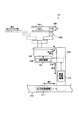
次に、図1に示した表面洗浄ユニットSSについて説明する。図7は表面洗浄ユニットSSの構成を説明するための図である。図7に示す表面洗浄ユニットSSでは、ブラシを用いた基板Wの洗浄処理(以下、スクラブ洗浄処理と呼ぶ)が行われる。
(6) Details of Surface Cleaning Unit Next, the surface cleaning unit SS shown in FIG. 1 will be described. FIG. 7 is a view for explaining the configuration of the surface cleaning unit SS. In the surface cleaning unit SS shown in FIG. 7, a cleaning process (hereinafter referred to as a scrub cleaning process) of the substrate W using a brush is performed.
まず、図7を用いて表面洗浄ユニットSSの詳細について説明する。図7に示すように、表面洗浄ユニットSSは、基板Wを水平に保持するとともに基板Wの中心を通る鉛直軸の周りで基板Wを回転させるためのスピンチャック61を備える。スピンチャック61は、チャック回転駆動機構62によって回転される回転軸63の上端に固定されている。
First, details of the surface cleaning unit SS will be described with reference to FIG. As shown in FIG. 7, the surface cleaning unit SS includes a
上記のように、表面洗浄ユニットSSには表面が上方に向けられた状態の基板Wが搬入される。スクラブ洗浄処理を行う場合には、スピンチャック61により基板Wの裏面が吸着保持される。
As described above, the substrate W whose surface is directed upward is carried into the surface cleaning unit SS. When performing the scrub cleaning process, the back surface of the substrate W is sucked and held by the
スピンチャック61の外方には、モータ64が設けられている。モータ64には、回動軸65が接続されている。回動軸65には、アーム66が水平方向に延びるように連結され、アーム66の先端に略円筒形状のブラシ洗浄具70が設けられている。
A
また、スピンチャック61の上方には、スピンチャック61により保持された基板Wの表面に向けて洗浄液またはリンス液(純水)を供給するための液吐出ノズル71が設けられている。
Further, a
液吐出ノズル71には供給管72が接続されており、この供給管72を通して液吐出ノズル71に洗浄液およびリンス液が選択的に供給される。
A
スクラブ洗浄処理時には、モータ64が回動軸65を回転させる。これにより、アーム66が水平面内で回動し、ブラシ洗浄具70が回動軸65を中心として基板Wの外方位置と基板Wの中心の上方位置との間で移動する。モータ64には、図示しない昇降機構が設けられている。昇降機構は、回動軸65を上昇および下降させることにより、基板Wの外方位置、および基板Wの中心の上方位置でブラシ洗浄具70を下降および上昇させる。
During the scrub cleaning process, the
スクラブ洗浄処理の開始時には、表面が上方に向けられた状態の基板Wがスピンチャック61により回転される。また、供給管72を通して洗浄液吐出ノズル71に洗浄液またはリンス液が供給される。これにより、回転する基板Wの表面に洗浄液またはリンス液が供給される。この状態で、ブラシ洗浄具70が回動軸65およびアーム66により揺動および昇降動作される。それにより、基板Wの表面に対してスクラブ洗浄処理が行われる。なお、表面洗浄ユニットSSにおいては吸着式のスピンチャック61を用いているため、基板Wの周縁部および外周端部も同時に洗浄することができる。
At the start of the scrub cleaning process, the substrate W whose surface is directed upward is rotated by the
(7)効果
図4を用いて説明したように、インデクサロボットIRにおけるハンドIRH1とハンドIRH2との高さの差は所定の範囲内で変化させることが可能である。
(7) Effect As described with reference to FIG. 4, the difference in height between the hand IRH1 and the hand IRH2 in the indexer robot IR can be changed within a predetermined range.
したがって、インデクサロボットIRは、キャリアCから2枚の基板Wを取り出す際に、上下に隣接する基板収納溝C2間の間隔GAに応じてハンドIRH1とハンドIRH2との高さの差を小さく(例えば、10mm程度)調整することができる。 Therefore, when taking out the two substrates W from the carrier C, the indexer robot IR reduces the difference in height between the hand IRH1 and the hand IRH2 according to the gap GA between the substrate storage grooves C2 adjacent in the vertical direction (for example, (About 10 mm) can be adjusted.
これにより、インデクサロボットIRは、ハンドIRH1およびハンドIRH2をキャリアC内に収納された複数の基板W間に挿入し、上下に隣接して収納された2枚の基板Wを容易に取り出すことができる。 Thereby, the indexer robot IR can easily take out the two substrates W stored adjacent to each other in the vertical direction by inserting the hand IRH1 and the hand IRH2 between the plurality of substrates W stored in the carrier C. .
また、インデクサロボットIRは、取り出した2枚の基板Wを基板載置部PASS2へ搬送する間に、上下に隣接する支持板51間の間隔GCに応じてハンドIRH1とハンドIRH2との高さの差を大きく(例えば、45mm程度)調整することができる。
In addition, the indexer robot IR moves the height of the hand IRH1 and the hand IRH2 according to the interval GC between the
これにより、インデクサロボットIRは、ハンドIRH1およびハンドIRH2が保持する2枚の基板Wを基板載置部PASS2の上下に隣接する支持板51上に容易に載置することができる。
Thereby, the indexer robot IR can easily place the two substrates W held by the hand IRH1 and the hand IRH2 on the
さらに、インデクサロボットIRは、2枚の基板Wを基板載置部PASS1からキャリアCに搬送する際にも、同様にハンドIRH1とハンドIRH2との高さの差を調整することができる。 Furthermore, the indexer robot IR can similarly adjust the difference in height between the hand IRH1 and the hand IRH2 when transporting the two substrates W from the substrate platform PASS1 to the carrier C.
これにより、キャリアCと基板載置部PASS1,PASS2との間で、基板Wを2枚ずつ搬送することが可能となっている。その結果、キャリアCと基板載置部PASS1,PASS2との間での基板Wの搬送時間が短縮され、基板処理装置100におけるスループットの向上が実現されている。
Thereby, it is possible to transport two substrates W between the carrier C and the substrate platforms PASS1, PASS2. As a result, the transfer time of the substrate W between the carrier C and the substrate platforms PASS1, PASS2 is shortened, and the throughput of the
なお、インデクサロボットIRにおいては、多関節型アームIAM1,IAM2が図示しない駆動機構によりそれぞれ独立に駆動されるので、キャリアCと基板載置部PASS1,PASS2との間で、基板Wを1枚ずつ搬送することも可能となっている。 In the indexer robot IR, the articulated arms IAM1 and IAM2 are independently driven by a driving mechanism (not shown), so that one substrate W is placed between the carrier C and the substrate platform PASS1 and PASS2. It can also be transported.
(8)変形例
本実施の形態では、表面洗浄ユニットSSにおいて、ブラシを用いて基板Wの表面を洗浄するが、これに限らず、薬液を用いて基板Wの表面を洗浄してもよい。
(8) Modification In the present embodiment, in the surface cleaning unit SS, the surface of the substrate W is cleaned using a brush, but the present invention is not limited thereto, and the surface of the substrate W may be cleaned using a chemical solution.
また、メインロボットMRは、未処理の基板Wを保持する際にはハンドMRH2を用い、スクラブ洗浄処理が施された基板Wを保持する際にはハンドMRH1を用いるが、これとは逆に、未処理の基板Wを保持する際にはハンドMRH1を用い、スクラブ洗浄処理が施された基板Wを保持する際にはハンドMRH2を用いてもよい。 The main robot MR uses the hand MRH2 when holding the unprocessed substrate W and uses the hand MRH1 when holding the substrate W that has been subjected to the scrub cleaning process. The hand MRH1 may be used when holding the unprocessed substrate W, and the hand MRH2 may be used when holding the substrate W that has been subjected to the scrub cleaning process.
さらに、上記では、インデクサロボットIRおよびメインロボットMRとして、関節を動かすことにより直線的にハンドの進退動作を行う多関節型搬送ロボットを用いているが、これに限定されず、基板Wに対して直線的にスライドさせてハンドの進退動作を行う直動型搬送ロボットを用いてもよい。 Further, in the above, as the indexer robot IR and the main robot MR, an articulated transfer robot that moves the joint linearly by moving the joint is used, but the present invention is not limited to this. A linear motion transfer robot that slides linearly and moves the hand back and forth may be used.
本実施の形態において、ハンドMRH1とハンドMRH2との高さの差M1(図6(a))が、図3(b)に示される基板載置部PASS1,PASS2の上下に隣接する支持板51間の間隔GCとほぼ等しくなるように設定されている場合、メインロボットMRは基板載置部PASS1,PASS2に対して2枚の基板Wを受け渡してもよい。
In the present embodiment, the height difference M1 (FIG. 6A) between the hand MRH1 and the hand MRH2 is the
この場合、メインロボットMRは、ハンドMRH1およびハンドMRH2を基板載置部PASS1,PASS2の隣接する支持板51間に挿入し、上下に隣接して載置された2枚の基板Wを容易に取り出すことができる。また、ハンドMRH1およびハンドMRH2に保持する2枚の基板Wを、基板載置部PASS1,PASS2の隣接する支持板51上に載置することができる。
In this case, the main robot MR inserts the hand MRH1 and the hand MRH2 between the
これにより、基板載置部PASS1,PASS2と表面洗浄ユニットSSとの間の基板Wの搬送時間を短縮することができる。 Thereby, the conveyance time of the board | substrate W between board | substrate mounting part PASS1, PASS2 and surface cleaning unit SS can be shortened.
本実施の形態において、インデクサロボットIRに設けられるハンドIRH1,IRH2は2本であるが、インデクサロボットIRに設けられるハンドの数は2本以上であればよく、特に限定されない。例えば、3本であってもよいし、4本であってもよい。 In the present embodiment, there are two hands IRH1 and IRH2 provided in the indexer robot IR, but the number of hands provided in the indexer robot IR is not particularly limited as long as it is two or more. For example, the number may be three or four.
[2]第2の実施の形態
第2の実施の形態に係る基板処理装置は、以下の点で第1の実施の形態に係る基板処理装置100と構成が異なる。
[2] Second Embodiment The substrate processing apparatus according to the second embodiment is different in configuration from the
(1)基板載置部の構成
本実施の形態に係る基板処理装置に用いられる基板載置部は、以下の構成を有する。図8は、第2の実施の形態に係る基板処理装置に用いられる基板載置部の構造を説明するための図である。
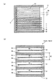
(1) Configuration of Substrate Placement Unit The substrate placement unit used in the substrate processing apparatus according to the present embodiment has the following configuration. FIG. 8 is a view for explaining the structure of the substrate platform used in the substrate processing apparatus according to the second embodiment.
図8(a)に本実施の形態の基板載置部PASS1,PASS2の平面図が示され、図8(b)に図8(a)のB−B線断面が示されている。 FIG. 8A shows a plan view of the substrate platforms PASS1, PASS2 of the present embodiment, and FIG. 8B shows a cross section taken along line BB of FIG. 8A.
図8(a)および図8(b)に示すように、本実施の形態の基板載置部PASS1,PASS2は、水平面内で対向するように配置される複数組の支持板51Pを備える。各組の支持板51Pは、複数のシリンダ510により多段に積層されている。各組の支持板51P上には基板Wの下面を支持する複数の支持ピンPNが設けられている。
As shown in FIG. 8A and FIG. 8B, the substrate platforms PASS1, PASS2 of the present embodiment include a plurality of sets of
各組における2枚の支持板51P間には、インデクサロボットIRのハンドIRH1,IRH2およびメインロボットMRのハンドMRH1,MRH2が挿入可能となっている。これにより、インデクサロボットIRおよびメインロボットMRにより搬送される基板Wが、各組の支持板51Pに設けられた複数の支持ピンPN上に一時的に載置される。
Between the two
上記のシリンダ510としては、例えばエアシリンダまたはオイルシリンダ等が用いられる。各シリンダ510は、ともにシリンダ同期機構500に接続されている。シリンダ同期機構500は、制御部4により制御され、複数のシリンダ510に同期を取りつつ、流体(例えば、空気またはオイル等)を複数のシリンダ510に供給する。
As the
これにより、各シリンダ510は、シリンダ同期機構500からの流体(例えば、空気またはオイル等)の供給量に応じて鉛直方向に伸縮動作する。それにより、本実施の形態の基板載置部PASS1,PASS2においては、上下に隣接する支持板51P間の間隔GCが所定の範囲内で変化する。
Accordingly, each
図9は、図8の基板載置部PASS1,PASS2において、上下に隣接する支持板51P間の間隔GCが変化する場合の一例を示す図である。
FIG. 9 is a diagram illustrating an example of a case where the interval GC between the
図9に示すように、上下に隣接する支持板51P間の間隔GCは、例えば点線で示される最大の間隔HG3から実線で示される最小の間隔HG4まで変化する。
As shown in FIG. 9, the interval GC between the upper and
支持板51P間の最大間隔HG3は、例えば図6(a)のメインロボットMRのハンドMRH1とハンドMRH2との高さの差M1とほぼ等しくなるように設定される。また、支持板51P間の最小間隔HG4は、例えば図3(a)の間隔GAと等しくなるように、例えば10mm程度に設定される。
For example, the maximum distance HG3 between the
なお、支持板51P間の最大間隔HG3は、例えば図3(b)の間隔GCと等しくなるように、45mm程度に設定されてもよい。
The maximum distance HG3 between the
本実施の形態の基板載置部PASS1,PASS2においても、各組の支持板51Pに対応して、基板Wの有無を検出する光学式のセンサ(図示せず)が設けられている。
Also in the substrate platforms PASS1 and PASS2 of the present embodiment, optical sensors (not shown) for detecting the presence or absence of the substrate W are provided corresponding to each set of
(2)インデクサロボットの構成
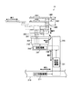
図10は、第2の実施の形態に係る基板処理装置に用いられるインデクサロボットIRの側面図である。図10に示すように、本実施の形態のインデクサロボットIRには、図4のモータ251、昇降軸260およびボールねじ261が設けられていない。
(2) Configuration of Indexer Robot FIG. 10 is a side view of the indexer robot IR used in the substrate processing apparatus according to the second embodiment. As shown in FIG. 10, the indexer robot IR of the present embodiment is not provided with the
本実施の形態のインデクサロボットIRにおいては、回転ステージ250上に、多関節型アームIAM1を介してハンドIRH1が接続され、多関節型アームIAM2を介してハンドIRH2が接続されている。
In the indexer robot IR of the present embodiment, a hand IRH1 is connected to a
これにより、多関節型アームIAM1,IAM2は、回転ステージ250に対して鉛直方向に移動せず、回転ステージ250に対して一定の高さに設けられる。それにより、ハンドIRH1とハンドIRH2との高さの差N1(図10)が一定に維持される。
As a result, the articulated arms IAM1 and IAM2 do not move in the vertical direction with respect to the
ここで、ハンドIRH1とハンドIRH2との高さの差N1は、例えば図3(a)の間隔GAと等しくなるように、例えば10mm程度に設定される。 Here, the height difference N1 between the hand IRH1 and the hand IRH2 is set to, for example, about 10 mm so as to be equal to the interval GA in FIG.
(3)効果
本実施の形態において、インデクサロボットIRにおけるハンドIRH1とハンドIRH2との高さの差N1(図10)はキャリアC内で上下に隣接する基板収納溝C2間の間隔GAと等しくなるように設定されている。
(3) Effects In this embodiment, the height difference N1 (FIG. 10) between the hand IRH1 and the hand IRH2 in the indexer robot IR is equal to the gap GA between the substrate storage grooves C2 that are vertically adjacent in the carrier C. Is set to
これにより、インデクサロボットIRは、キャリアCから2枚の基板Wを取り出す際に、ハンドIRH1およびハンドIRH2をキャリアC内に収納された複数の基板W間に挿入し、上下に隣接して収納された2枚の基板Wを容易に取り出すことができる。 Thus, when the indexer robot IR takes out the two substrates W from the carrier C, the indexer robot IR inserts the hand IRH1 and the hand IRH2 between the plurality of substrates W stored in the carrier C, and is stored adjacent to the top and bottom. The two substrates W can be easily taken out.
ここで、図8および図9を用いて説明したように、基板載置部PASS1,PASS2の上下に隣接する支持板51P間の間隔GCは、所定の範囲内で変化する。
Here, as described with reference to FIGS. 8 and 9, the interval GC between the
したがって、基板載置部PASS1,PASS2は、例えばインデクサロボットIRにより2枚の基板Wが搬送される際に、上下に隣接する支持板51間の間隔GCを最小間隔HG4に調整することができる。
Accordingly, the substrate platforms PASS1 and PASS2 can adjust the interval GC between the
上述のように、支持板51P間の最小間隔HG4は、キャリアC内で上下に隣接する基板収納溝C2間の間隔GAと等しい。これにより、インデクサロボットIRは、ハンドIRH1とハンドIRH2との高さの差N1が基板収納溝C2間の間隔GAと等しいので、ハンドIRH1およびハンドIRH2に保持する2枚の基板Wを容易に基板載置部PASS2の支持板51P上に載置することができる。
As described above, the minimum interval HG4 between the
また、インデクサロボットIRは、ハンドIRH1およびハンドIRH2を用いることにより、基板載置部PASS1の支持板51P上に載置された2枚の基板Wを容易に取り出すことができる。
Further, the indexer robot IR can easily take out the two substrates W placed on the
それにより、本実施の形態に係る基板処理装置100においても、キャリアCと基板載置部PASS1,PASS2との間で、基板Wを2枚ずつ搬送することが可能となっている。その結果、基板処理装置100のスループットの向上が実現されている。
Thereby, also in the
基板載置部PASS1,PASS2は、例えばメインロボットMRにより基板Wが表面洗浄ユニットSSへ搬送される際に、上下に隣接する支持板51間の間隔GCを最大間隔HG3に調整することができる。
The substrate platforms PASS1, PASS2 can adjust the interval GC between the upper and
支持板51P間の最大間隔HG3は、キャリアC内で上下に隣接する基板収納溝C2間の間隔GAよりも十分に大きく、メインロボットMRのハンドMRH1とハンドMRH2との高さの差M1にほぼ等しい。
The maximum distance HG3 between the
これにより、インデクサロボットIRのハンドIRH1,IRH2よりも大きい厚みを有するメインロボットMRのハンドMRH1,MRH2が、基板載置部PASS1,PASS2の支持板51P上に載置された複数の基板W間に容易に挿入される。それにより、メインロボットMRと基板載置部PASS1,PASS2との間の基板Wの受け渡しが確実に行われる。
Thereby, the hands MRH1 and MRH2 of the main robot MR having a thickness larger than the hands IRH1 and IRH2 of the indexer robot IR are placed between the plurality of substrates W placed on the
[3]請求項の各構成要素と実施の形態の各要素との対応
以下、請求項の各構成要素と実施の形態の各要素との対応の例について説明するが、本発明は下記の例に限定されない。
[3] Correspondence between Each Component in Claim and Each Element in Embodiment The following describes an example of correspondence between each component in the claim and each element in the embodiment. It is not limited to.
上記実施の形態では、キャリアCが収納容器の例であり、支持板51,51Pが収納棚の例であり、基板載置部PASS1,PASS2が基板載置棚および受け渡し部の例であり、インデクサロボットIRが基板搬送装置および第1の基板搬送装置の例である。
In the above embodiment, the carrier C is an example of a storage container, the
また、搬送レール部210、水平移動機構211、移動支持柱220、鉛直移動機構221、昇降支持部230、ベース部240、回転機構241、回転ステージ250、および多関節型アームIAM1,IAM2が駆動機構の例である。
Further, the
また、ハンドIRH1が第1の基板保持部の例であり、ハンドIRH2が第2の基板保持部の例であり、モータ251、昇降軸260およびボールねじ261、ならびにシリンダ同期機構500およびシリンダ510が調整機構の例である。
The hand IRH1 is an example of the first substrate holding unit, the hand IRH2 is an example of the second substrate holding unit, the
また、ハンドMRH1が第3の保持部の例であり、ハンドMRH2が第4の保持部の例であり、メインロボットMRが第2の基板搬送装置の例であり、支持ピンPNが支持部材の例であり、処理ブロック11が処理領域の例であり、インデクサブロック10が搬入搬出領域の例であり、キャリア載置台40が容器載置部の例であり、表面洗浄ユニットSSが処理部および洗浄処理部の例である。
The hand MRH1 is an example of a third holding unit, the hand MRH2 is an example of a fourth holding unit, the main robot MR is an example of a second substrate transfer device, and the support pin PN is a support member. For example, the
なお、請求項の各構成要素として、請求項に記載されている構成または機能を有する他の種々の要素を用いることもできる。 In addition, as each component of a claim, the other various element which has the structure or function described in the claim can also be used.
本発明は、半導体ウェハ、フォトマスク用ガラス基板、液晶表示装置用ガラス基板、プラズマディスプレイ用ガラス基板、光ディスク用基板、磁気ディスク用基板、光磁気ディスク用基板等の基板の製造に有効に利用できる。 INDUSTRIAL APPLICABILITY The present invention can be effectively used for manufacturing substrates such as semiconductor wafers, glass substrates for photomasks, glass substrates for liquid crystal display devices, glass substrates for plasma displays, optical disk substrates, magnetic disk substrates, and magneto-optical disk substrates. .
10 インデクサブロック
11 処理ブロック
40 キャリア載置台
51,51P 支持板
100 基板処理装置
210 搬送レール部
211 水平移動機構
220 移動支持柱
221 鉛直移動機構
230 昇降支持部
240 ベース部
241 回転機構
250 回転ステージ
251 モータ
260 昇降軸
261 ボールねじ
500 シリンダ同期機構
510 シリンダ
C キャリア
C2 基板収納溝
IR インデクサロボット
IAM1,IAM2 多関節型アーム
IRH1,IRH2,MRH1,MRH2 ハンド
MR メインロボット
PASS1,PASS2 基板載置部
PN 支持ピン
SS 表面洗浄ユニット
W 基板
DESCRIPTION OF
Claims (8)
互いに上下に設けられ、基板を略水平姿勢で保持する第1および第2の基板保持部と、
前記収納容器および前記基板載置棚に対して基板の受け渡しを行うために前記第1および第2の基板保持部を移動させるとともに略水平方向に進退させる駆動機構と、
前記第1および前記第2の基板保持部間の高さの差を調整する調整機構とを備え、
前記調整機構は、前記収納容器と前記第1および第2の基板保持部との間での基板の受け渡しの際に、前記第1および第2の基板保持部間の高さの差を前記収納容器の前記収納溝間の高さの差に調整し、前記基板載置棚と前記第1および第2の基板保持部との間での基板の受け渡しの際に、前記第1および第2の基板保持部間の高さの差を前記基板載置棚の収納棚間の高さの差に調整することを特徴とする基板搬送装置。 A substrate for transporting a substrate between a storage container having a plurality of storage grooves in which the substrate is stored in a substantially horizontal posture and a substrate mounting shelf having a plurality of storage shelves in which the substrate is mounted in a substantially horizontal posture. A conveying device,
First and second substrate holders that are provided one above the other and hold the substrate in a substantially horizontal posture;
A drive mechanism that moves the first and second substrate holders and moves them back and forth in a substantially horizontal direction in order to transfer the substrates to the storage container and the substrate mounting shelf;
An adjustment mechanism for adjusting a difference in height between the first and second substrate holders,
The adjusting mechanism stores the difference in height between the first and second substrate holders when the substrate is transferred between the storage container and the first and second substrate holders. When adjusting the height difference between the storage grooves of the container and transferring the substrate between the substrate mounting shelf and the first and second substrate holders, the first and second A substrate transfer apparatus, wherein a difference in height between substrate holding portions is adjusted to a difference in height between storage shelves of the substrate mounting shelf.
基板を略水平姿勢でそれぞれ支持する複数段の収納棚と、
収納棚間の高さの差を調整する調整機構とを備え、
前記調整機構は、前記第1の基板搬送装置との間での基板の受け渡しの際に、前記収納棚間の高さの差を前記第1および第2の基板保持部間の高さの差に調整し、前記第2の基板搬送装置との間での基板の受け渡しの際に、前記収納棚間の高さの差を前記第3および第4の基板保持部間の高さの差に調整することを特徴とする基板載置棚。 Between a first substrate transport device having first and second substrate holders provided above and below each other and a second substrate transport device having third and fourth substrate holders provided above and below each other A substrate mounting shelf for delivering the substrate at
A plurality of storage shelves for supporting the substrates in a substantially horizontal position, and
An adjustment mechanism for adjusting the height difference between the storage shelves,
The adjustment mechanism is configured to determine a difference in height between the storage shelves when the substrate is transferred to and from the first substrate transfer device. And adjusting the difference in height between the storage shelves to the difference in height between the third and fourth substrate holders when transferring the substrate to and from the second substrate transfer device. A substrate mounting shelf that is adjusted.
基板を処理する処理領域と、
前記処理領域に対して基板を搬入および搬出する搬入搬出領域と、
前記処理領域と前記搬入搬出領域との間で基板を受け渡す受け渡し部とを備え、
前記搬入搬出領域は、
基板が略水平姿勢で収納される複数段の収納溝を有する収納容器が載置される容器載置部と、
前記容器載置部に載置された収納容器と前記受け渡し部との間で基板を搬送する第1の基板搬送装置とを含み、
前記処理領域は、
基板に処理を行う処理部と、
前記受け渡し部と前記処理部との間で基板を搬送する第2の基板搬送装置とを含み、
前記受け渡し部は、
基板が略水平姿勢で載置される複数段の収納棚を有する基板載置棚を含み、
前記第1の基板搬送装置は、
互いに上下に設けられ、基板を略水平姿勢で保持する第1および第2の基板保持部と、
前記収納容器および前記基板載置棚に対して基板の受け渡しを行うために前記第1および第2の基板保持部を移動させるとともに略水平方向に進退させる駆動機構と、
前記第1および前記第2の基板保持部間の高さの差を調整する調整機構とを備え、
前記調整機構は、前記収納容器と前記第1および第2の基板保持部との間での基板の受け渡しの際に、前記第1および第2の基板保持部間の高さの差を前記収納容器の前記収納溝間の高さの差に調整し、前記基板載置棚と前記第1および第2の基板保持部との間での基板の受け渡しの際に、前記第1および第2の基板保持部間の高さの差を前記基板載置棚の収納棚間の高さの差に調整することを特徴とする基板処理装置。 A substrate processing apparatus for processing a substrate,
A processing area for processing the substrate;
A loading / unloading area for loading and unloading the substrate with respect to the processing area;
A delivery section for delivering a substrate between the processing area and the carry-in / out area;
The carry-in / out area is
A container mounting portion on which a storage container having a plurality of storage grooves in which the substrate is stored in a substantially horizontal posture is mounted;
A first substrate transfer device that transfers a substrate between the storage container placed on the container placement unit and the delivery unit;
The processing area is
A processing unit for processing the substrate;
A second substrate transfer device for transferring a substrate between the delivery unit and the processing unit;
The delivery unit is
Including a substrate mounting shelf having a plurality of storage shelves on which the substrate is mounted in a substantially horizontal posture;
The first substrate transfer device includes:
First and second substrate holders that are provided one above the other and hold the substrate in a substantially horizontal posture;
A drive mechanism that moves the first and second substrate holders and moves them back and forth in a substantially horizontal direction in order to transfer the substrates to the storage container and the substrate mounting shelf;
An adjustment mechanism for adjusting a difference in height between the first and second substrate holders,
The adjusting mechanism stores the difference in height between the first and second substrate holders when the substrate is transferred between the storage container and the first and second substrate holders. When adjusting the height difference between the storage grooves of the container and transferring the substrate between the substrate mounting shelf and the first and second substrate holders, the first and second A substrate processing apparatus for adjusting a difference in height between substrate holders to a difference in height between storage shelves of the substrate mounting shelf.
基板を処理処理領域と、
前記処理領域に対して基板を搬入および搬出する搬入搬出領域と、
前記処理領域と前記搬入搬出領域との間で基板を受け渡す受け渡し部とを備え、
前記搬入搬出領域は、
基板が略水平姿勢で収納される複数段の収納溝を有する収納容器が載置される容器載置部と、
互いに上下に設けられた第1および第2の基板保持部を有し、前記容器載置部に載置された収納容器と前記受け渡し部との間で基板を搬送する第1の基板搬送装置とを含み、
前記処理領域は、
基板に処理を行う処理部と、
互いに上下に設けられた第3および第4の基板保持部を有し、前記受け渡し部と前記処理部との間で基板を搬送する第2の基板搬送装置とを含み、
前記受け渡し部は、
基板が略水平姿勢で載置される複数段の収納棚を有する基板載置棚を含み、
前記基板載置棚は、
基板を略水平姿勢でそれぞれ支持する複数段の収納棚と、
収納棚間の高さの差を調整する調整機構とを備え、
前記調整機構は、前記第1の基板搬送装置との間での基板の受け渡しの際に、前記収納棚間の高さの差を前記第1および第2の基板保持部間の高さの差に調整し、前記第2の基板搬送装置との間での基板の受け渡しの際に、前記収納棚間の高さの差を前記第3および第4の基板保持部間の高さの差に調整することを特徴とする基板処理装置。 A substrate processing apparatus for processing a substrate,
A substrate processing area,
A loading / unloading area for loading and unloading the substrate with respect to the processing area;
A delivery section for delivering a substrate between the processing area and the carry-in / out area;
The carry-in / out area is
A container mounting portion on which a storage container having a plurality of storage grooves in which the substrate is stored in a substantially horizontal posture is mounted;
A first substrate transport device that includes first and second substrate holders provided above and below, and that transports a substrate between a storage container placed on the container placement unit and the transfer unit; Including
The processing area is
A processing unit for processing the substrate;
A second substrate transport device that includes third and fourth substrate holders provided above and below each other and transports a substrate between the transfer unit and the processing unit;
The delivery unit is
Including a substrate mounting shelf having a plurality of storage shelves on which the substrate is mounted in a substantially horizontal posture;
The substrate mounting shelf is
A plurality of storage shelves for supporting the substrates in a substantially horizontal position, and
An adjustment mechanism for adjusting the height difference between the storage shelves,
The adjustment mechanism is configured to determine a difference in height between the storage shelves when the substrate is transferred to and from the first substrate transfer device. And adjusting the difference in height between the storage shelves to the difference in height between the third and fourth substrate holders when transferring the substrate to and from the second substrate transfer device. A substrate processing apparatus characterized by adjusting.
Priority Applications (7)
| Application Number | Priority Date | Filing Date | Title |
|---|---|---|---|
| JP2006352000A JP4744427B2 (en) | 2006-12-27 | 2006-12-27 | Substrate processing equipment |
| US11/958,816 US20080159832A1 (en) | 2006-12-27 | 2007-12-18 | Substrate transporting apparatus, substrate platform shelf and substrate processing apparatus |
| KR1020070135430A KR100927302B1 (en) | 2006-12-27 | 2007-12-21 | Substrate Processing Equipment |
| CN201010198915XA CN101872736B (en) | 2006-12-27 | 2007-12-27 | Substrate processing equipment |
| TW096150475A TWI455234B (en) | 2006-12-27 | 2007-12-27 | Substrate processing device |
| CN2007103056009A CN101221918B (en) | 2006-12-27 | 2007-12-27 | Substrate carrying device, substrate carrying frame and substrate processing device |
| US12/886,063 US8500915B2 (en) | 2006-12-27 | 2010-09-20 | Substrate transporting apparatus, substrate platform shelf and substrate processing apparatus |
Applications Claiming Priority (1)
| Application Number | Priority Date | Filing Date | Title |
|---|---|---|---|
| JP2006352000A JP4744427B2 (en) | 2006-12-27 | 2006-12-27 | Substrate processing equipment |
Publications (2)
| Publication Number | Publication Date |
|---|---|
| JP2008166370A true JP2008166370A (en) | 2008-07-17 |
| JP4744427B2 JP4744427B2 (en) | 2011-08-10 |
Family
ID=39584217
Family Applications (1)
| Application Number | Title | Priority Date | Filing Date |
|---|---|---|---|
| JP2006352000A Expired - Fee Related JP4744427B2 (en) | 2006-12-27 | 2006-12-27 | Substrate processing equipment |
Country Status (5)
| Country | Link |
|---|---|
| US (2) | US20080159832A1 (en) |
| JP (1) | JP4744427B2 (en) |
| KR (1) | KR100927302B1 (en) |
| CN (2) | CN101221918B (en) |
| TW (1) | TWI455234B (en) |
Cited By (11)
| Publication number | Priority date | Publication date | Assignee | Title |
|---|---|---|---|---|
| JP2010045214A (en) * | 2008-08-13 | 2010-02-25 | Dainippon Screen Mfg Co Ltd | Substrate carrying device and substrate treatment device having the same |
| JP2010129769A (en) * | 2008-11-27 | 2010-06-10 | Tokyo Electron Ltd | Substrate processing system |
| JP2010192685A (en) * | 2009-02-18 | 2010-09-02 | Tokyo Electron Ltd | Substrate conveying device and substrate processing system |
| CN101859723A (en) * | 2009-04-01 | 2010-10-13 | 东京毅力科创株式会社 | Substrate exchange method and substrate processing apparatus |
| JP2010238783A (en) * | 2009-03-30 | 2010-10-21 | Dainippon Screen Mfg Co Ltd | Substrate processing apparatus and substrate transfer method |
| JP2012501533A (en) * | 2008-08-28 | 2012-01-19 | セメス カンパニー リミテッド | Method for adjusting speed of transfer member, substrate transfer method and substrate processing apparatus using the same |
| JP2012501534A (en) * | 2008-08-28 | 2012-01-19 | セメス カンパニー リミテッド | Substrate processing apparatus and substrate transfer method |
| JP2012160759A (en) * | 2012-05-15 | 2012-08-23 | Dainippon Screen Mfg Co Ltd | Substrate carrying device and substrate processing device having the same |
| JP2013098288A (en) * | 2011-10-31 | 2013-05-20 | Disco Abrasive Syst Ltd | Carrier device |
| KR101495241B1 (en) | 2010-12-24 | 2015-02-24 | 카와사키 주코교 카부시키 카이샤 | Transportation robot, substrate transportation method therefor, and substrate transportation relay apparatus |
| JP2017085127A (en) * | 2011-03-11 | 2017-05-18 | ブルックス オートメーション インコーポレイテッド | Substrate processing tool |
Families Citing this family (23)
| Publication number | Priority date | Publication date | Assignee | Title |
|---|---|---|---|---|
| US8430620B1 (en) | 2008-03-24 | 2013-04-30 | Novellus Systems, Inc. | Dedicated hot and cold end effectors for improved throughput |
| DE102009009548A1 (en) * | 2009-02-19 | 2010-09-09 | Jonas & Redmann Automationstechnik Gmbh | A method of forming a packet-like back-to-back wafer batch |
| JP5037551B2 (en) * | 2009-03-24 | 2012-09-26 | 東京エレクトロン株式会社 | Substrate replacement mechanism and substrate replacement method |
| JP5347652B2 (en) * | 2009-03-30 | 2013-11-20 | 株式会社Ihi | Substrate lifting / lowering transfer apparatus and substrate processing / transfer system |
| TWI451519B (en) * | 2010-10-19 | 2014-09-01 | Au Optronics Corp | Method for transporting and processing substrate |
| CN102064126B (en) * | 2010-11-04 | 2013-04-17 | 友达光电股份有限公司 | Substrate transport handling method |
| JP5666361B2 (en) * | 2011-03-29 | 2015-02-12 | 株式会社Screenセミコンダクターソリューションズ | Substrate processing equipment |
| KR20140087038A (en) * | 2011-12-15 | 2014-07-08 | 다즈모 가부시키가이샤 | Wafer conveyance device |
| JP5993625B2 (en) * | 2012-06-15 | 2016-09-14 | 株式会社Screenホールディングス | Substrate reversing apparatus and substrate processing apparatus |
| US9245783B2 (en) | 2013-05-24 | 2016-01-26 | Novellus Systems, Inc. | Vacuum robot with linear translation carriage |
| JP6190645B2 (en) * | 2013-07-09 | 2017-08-30 | 東京エレクトロン株式会社 | Substrate transfer method |
| US9214369B2 (en) * | 2013-11-01 | 2015-12-15 | Varian Semiconductor Equipment Associates, Inc. | Dynamic pitch substrate lift |
| JP6347333B2 (en) * | 2015-06-01 | 2018-06-27 | 株式会社ダイフク | Control method of loading / unloading device in flat storage facility |
| CN107552467A (en) * | 2017-09-24 | 2018-01-09 | 安徽海拓志永智能装备股份有限公司 | Suitable for the system of reaching the standard grade of glass cleaning |
| TWI668790B (en) * | 2018-04-30 | 2019-08-11 | 漢民科技股份有限公司 | Substrate transfer mechanism and film forming apparatus for semiconductor process |
| JP7114456B2 (en) * | 2018-12-28 | 2022-08-08 | 株式会社Screenホールディングス | SUBSTRATE PROCESSING APPARATUS AND SUBSTRATE TRANSFER METHOD |
| US11427412B2 (en) * | 2019-05-09 | 2022-08-30 | Kawasaki Jukogyo Kabushiki Kaisha | Substrate conveying robot and substrate conveying method |
| US11004713B2 (en) | 2019-05-16 | 2021-05-11 | Taiwan Semiconductor Manufacturing Co., Ltd. | Robot arm device and method for transferring wafer |
| CN110817225A (en) * | 2019-11-28 | 2020-02-21 | 国网新疆电力有限公司物资公司 | Automatic stacking robot for electronic material warehouse |
| KR102150230B1 (en) * | 2020-04-07 | 2020-08-31 | (주)볼타오토메이션 | Transfer apparatus having vacuum robot |
| JP7541457B2 (en) * | 2020-09-18 | 2024-08-28 | 株式会社Screenホールディングス | SUBSTRATE PROCESSING APPARATUS AND SUBSTRATE PROCESSING METHOD |
| KR20220106900A (en) | 2021-01-22 | 2022-08-01 | 삼성디스플레이 주식회사 | Cassette for loading panel and substrate processign method using the same |
| US12441557B2 (en) * | 2021-12-30 | 2025-10-14 | Semes Co., Ltd. | Apparatus and method for transporting articles |
Citations (2)
| Publication number | Priority date | Publication date | Assignee | Title |
|---|---|---|---|---|
| JPH0870033A (en) * | 1994-08-26 | 1996-03-12 | Kokusai Electric Co Ltd | Wafer transfer machine for semiconductor manufacturing equipment |
| JPH11130254A (en) * | 1997-10-24 | 1999-05-18 | Sharp Corp | Substrate transfer cassette |
Family Cites Families (10)
| Publication number | Priority date | Publication date | Assignee | Title |
|---|---|---|---|---|
| KR100310249B1 (en) * | 1995-08-05 | 2001-12-17 | 엔도 마코토 | Substrate Processing Equipment |
| TW318258B (en) * | 1995-12-12 | 1997-10-21 | Tokyo Electron Co Ltd | |
| JP3522469B2 (en) * | 1996-11-18 | 2004-04-26 | 大日本スクリーン製造株式会社 | Substrate processing apparatus and substrate processing method |
| JP3589839B2 (en) * | 1997-10-24 | 2004-11-17 | シャープ株式会社 | Substrate transfer device with pitch conversion |
| JP3974985B2 (en) | 1997-12-02 | 2007-09-12 | 大日本スクリーン製造株式会社 | Substrate transfer device |
| JP3888608B2 (en) * | 2001-04-25 | 2007-03-07 | 東京エレクトロン株式会社 | Substrate double-sided processing equipment |
| JP4283559B2 (en) * | 2003-02-24 | 2009-06-24 | 東京エレクトロン株式会社 | Conveying apparatus, vacuum processing apparatus, and atmospheric pressure conveying apparatus |
| JP2005072559A (en) * | 2003-08-05 | 2005-03-17 | Dainippon Screen Mfg Co Ltd | Substrate processing apparatus and substrate processing method |
| JP5154008B2 (en) * | 2004-11-10 | 2013-02-27 | 株式会社Sokudo | Substrate processing apparatus and substrate processing method |
| KR20060077960A (en) * | 2004-12-30 | 2006-07-05 | 삼성전자주식회사 | Reticle storage cassette |
-
2006
- 2006-12-27 JP JP2006352000A patent/JP4744427B2/en not_active Expired - Fee Related
-
2007
- 2007-12-18 US US11/958,816 patent/US20080159832A1/en not_active Abandoned
- 2007-12-21 KR KR1020070135430A patent/KR100927302B1/en not_active Expired - Fee Related
- 2007-12-27 TW TW096150475A patent/TWI455234B/en not_active IP Right Cessation
- 2007-12-27 CN CN2007103056009A patent/CN101221918B/en not_active Expired - Fee Related
- 2007-12-27 CN CN201010198915XA patent/CN101872736B/en not_active Expired - Fee Related
-
2010
- 2010-09-20 US US12/886,063 patent/US8500915B2/en not_active Expired - Fee Related
Patent Citations (2)
| Publication number | Priority date | Publication date | Assignee | Title |
|---|---|---|---|---|
| JPH0870033A (en) * | 1994-08-26 | 1996-03-12 | Kokusai Electric Co Ltd | Wafer transfer machine for semiconductor manufacturing equipment |
| JPH11130254A (en) * | 1997-10-24 | 1999-05-18 | Sharp Corp | Substrate transfer cassette |
Cited By (18)
| Publication number | Priority date | Publication date | Assignee | Title |
|---|---|---|---|---|
| JP2010045214A (en) * | 2008-08-13 | 2010-02-25 | Dainippon Screen Mfg Co Ltd | Substrate carrying device and substrate treatment device having the same |
| US8690516B2 (en) | 2008-08-28 | 2014-04-08 | Semes Co., Ltd. | Method of adjusting velocity of transfer member, method of transferring substrate using the method, and substrate-processing apparatus |
| US8615323B2 (en) | 2008-08-28 | 2013-12-24 | Semes Co., Ltd. | Substrate-processing apparatus and method of transferring substrate in the same |
| JP2012501533A (en) * | 2008-08-28 | 2012-01-19 | セメス カンパニー リミテッド | Method for adjusting speed of transfer member, substrate transfer method and substrate processing apparatus using the same |
| JP2012501534A (en) * | 2008-08-28 | 2012-01-19 | セメス カンパニー リミテッド | Substrate processing apparatus and substrate transfer method |
| KR101229010B1 (en) | 2008-11-27 | 2013-02-01 | 도쿄엘렉트론가부시키가이샤 | Substrate processing system |
| JP2010129769A (en) * | 2008-11-27 | 2010-06-10 | Tokyo Electron Ltd | Substrate processing system |
| JP2010192685A (en) * | 2009-02-18 | 2010-09-02 | Tokyo Electron Ltd | Substrate conveying device and substrate processing system |
| JP2010238783A (en) * | 2009-03-30 | 2010-10-21 | Dainippon Screen Mfg Co Ltd | Substrate processing apparatus and substrate transfer method |
| JP2010245127A (en) * | 2009-04-01 | 2010-10-28 | Tokyo Electron Ltd | Substrate replacement method and substrate processing apparatus |
| CN101859723A (en) * | 2009-04-01 | 2010-10-13 | 东京毅力科创株式会社 | Substrate exchange method and substrate processing apparatus |
| KR101495241B1 (en) | 2010-12-24 | 2015-02-24 | 카와사키 주코교 카부시키 카이샤 | Transportation robot, substrate transportation method therefor, and substrate transportation relay apparatus |
| JP2017085127A (en) * | 2011-03-11 | 2017-05-18 | ブルックス オートメーション インコーポレイテッド | Substrate processing tool |
| US10325795B2 (en) | 2011-03-11 | 2019-06-18 | Brooks Automation, Inc. | Substrate processing apparatus |
| US10600665B2 (en) | 2011-03-11 | 2020-03-24 | Brooks Automation, Inc. | Substrate processing apparatus |
| US11978649B2 (en) | 2011-03-11 | 2024-05-07 | Brooks Automation Us, Llc | Substrate processing apparatus |
| JP2013098288A (en) * | 2011-10-31 | 2013-05-20 | Disco Abrasive Syst Ltd | Carrier device |
| JP2012160759A (en) * | 2012-05-15 | 2012-08-23 | Dainippon Screen Mfg Co Ltd | Substrate carrying device and substrate processing device having the same |
Also Published As
| Publication number | Publication date |
|---|---|
| TW200836289A (en) | 2008-09-01 |
| CN101872736A (en) | 2010-10-27 |
| TWI455234B (en) | 2014-10-01 |
| KR100927302B1 (en) | 2009-11-18 |
| CN101221918A (en) | 2008-07-16 |
| US8500915B2 (en) | 2013-08-06 |
| KR20080061290A (en) | 2008-07-02 |
| CN101872736B (en) | 2012-10-24 |
| US20080159832A1 (en) | 2008-07-03 |
| US20110008148A1 (en) | 2011-01-13 |
| JP4744427B2 (en) | 2011-08-10 |
| CN101221918B (en) | 2010-07-14 |
Similar Documents
| Publication | Publication Date | Title |
|---|---|---|
| JP4744427B2 (en) | Substrate processing equipment | |
| JP5068738B2 (en) | Substrate processing apparatus and method | |
| JP4744426B2 (en) | Substrate processing apparatus and substrate processing method | |
| CN101246813B (en) | Substrate processing apparatus | |
| CN101211812B (en) | Substrate processing equipment | |
| JP4999487B2 (en) | Substrate processing equipment | |
| JP5274339B2 (en) | Substrate processing apparatus and substrate transfer method | |
| KR102157427B1 (en) | Substrate transfer robot and substrate processing system | |
| CN101211758B (en) | Substrate processing equipment | |
| JP4969138B2 (en) | Substrate processing equipment | |
| US11069546B2 (en) | Substrate processing system | |
| JP4869097B2 (en) | Substrate processing equipment | |
| JP5385965B2 (en) | Substrate processing equipment | |
| JP2005145713A (en) | Substrate transfer device |
Legal Events
| Date | Code | Title | Description |
|---|---|---|---|
| A621 | Written request for application examination |
Free format text: JAPANESE INTERMEDIATE CODE: A621 Effective date: 20090205 |
|
| A131 | Notification of reasons for refusal |
Free format text: JAPANESE INTERMEDIATE CODE: A131 Effective date: 20100914 |
|
| A977 | Report on retrieval |
Free format text: JAPANESE INTERMEDIATE CODE: A971007 Effective date: 20100916 |
|
| A521 | Request for written amendment filed |
Free format text: JAPANESE INTERMEDIATE CODE: A523 Effective date: 20101112 |
|
| TRDD | Decision of grant or rejection written | ||
| A01 | Written decision to grant a patent or to grant a registration (utility model) |
Free format text: JAPANESE INTERMEDIATE CODE: A01 Effective date: 20110510 |
|
| A01 | Written decision to grant a patent or to grant a registration (utility model) |
Free format text: JAPANESE INTERMEDIATE CODE: A01 |
|
| A61 | First payment of annual fees (during grant procedure) |
Free format text: JAPANESE INTERMEDIATE CODE: A61 Effective date: 20110510 |
|
| FPAY | Renewal fee payment (event date is renewal date of database) |
Free format text: PAYMENT UNTIL: 20140520 Year of fee payment: 3 |
|
| R150 | Certificate of patent or registration of utility model |
Ref document number: 4744427 Country of ref document: JP Free format text: JAPANESE INTERMEDIATE CODE: R150 Free format text: JAPANESE INTERMEDIATE CODE: R150 |
|
| R250 | Receipt of annual fees |
Free format text: JAPANESE INTERMEDIATE CODE: R250 |
|
| S533 | Written request for registration of change of name |
Free format text: JAPANESE INTERMEDIATE CODE: R313533 |
|
| R350 | Written notification of registration of transfer |
Free format text: JAPANESE INTERMEDIATE CODE: R350 |
|
| R250 | Receipt of annual fees |
Free format text: JAPANESE INTERMEDIATE CODE: R250 |
|
| R250 | Receipt of annual fees |
Free format text: JAPANESE INTERMEDIATE CODE: R250 |
|
| R250 | Receipt of annual fees |
Free format text: JAPANESE INTERMEDIATE CODE: R250 |
|
| R250 | Receipt of annual fees |
Free format text: JAPANESE INTERMEDIATE CODE: R250 |
|
| R250 | Receipt of annual fees |
Free format text: JAPANESE INTERMEDIATE CODE: R250 |
|
| LAPS | Cancellation because of no payment of annual fees |