JP2008166310A - Solder printing mask, printed wiring board, and circuit board manufacturing method - Google Patents
Solder printing mask, printed wiring board, and circuit board manufacturing method Download PDFInfo
- Publication number
- JP2008166310A JP2008166310A JP2006350652A JP2006350652A JP2008166310A JP 2008166310 A JP2008166310 A JP 2008166310A JP 2006350652 A JP2006350652 A JP 2006350652A JP 2006350652 A JP2006350652 A JP 2006350652A JP 2008166310 A JP2008166310 A JP 2008166310A
- Authority
- JP
- Japan
- Prior art keywords
- land
- component
- solder
- mounting
- printed wiring
- Prior art date
- Legal status (The legal status is an assumption and is not a legal conclusion. Google has not performed a legal analysis and makes no representation as to the accuracy of the status listed.)
- Pending
Links
Images
Landscapes
- Printing Plates And Materials Therefor (AREA)
- Electric Connection Of Electric Components To Printed Circuits (AREA)
Abstract
【課題】混載基板に印刷によりクリーム半田を印刷して半田コートを形成する際に、挿入部品用の貫通孔を塞ぐことのない半田印刷マスク、プリント配線基板及び回路基板の製造方法を提供することを目的とする。
【解決手段】プリント配線基板の実装面上に、表面実装部品と挿入部品とが実装されてなる回路基板の製造方法において、表面実装部品が半田付けされる第1のランド上に半田ペーストを印刷するとともに、挿入部品が半田付けされる第2のランド上に半田ペーストが複数の領域に分割されて印刷されるように印刷する工程と、半田ペーストが印刷された第1のランド上に、表面実装部品を搭載する工程と、基板を加熱して表面実装部品を第1のランドに半田付けするとともに、第2のランド上に半田による被膜を形成する工程と、挿入部品を第2のランドに半田付けする工程とを実施するものとする。
【選択図】図8Provided are a solder printing mask, a printed wiring board, and a method for manufacturing a circuit board that do not block a through hole for an insertion component when a solder coat is formed by printing cream solder on a mixed board by printing. With the goal.
In a circuit board manufacturing method in which a surface mounting component and an insertion component are mounted on a mounting surface of a printed wiring board, a solder paste is printed on a first land to which the surface mounting component is soldered. And a step of printing so that the solder paste is divided into a plurality of regions and printed on the second land to which the insertion component is soldered, and a surface on the first land on which the solder paste is printed. A step of mounting the mounting component, a step of heating the substrate and soldering the surface mounting component to the first land, forming a coating film with solder on the second land, and an insertion component on the second land. The soldering process is performed.
[Selection] Figure 8
Description
本発明は、半田印刷マスク、プリント配線基板及び回路基板の製造方法に関し、特に、表面実装部品と挿入部品とが実装されてなる回路基板の製造方法、及びこれに用いられる半田印刷マスクと、前記回路基板を構成するプリント配線基板に関する。 The present invention relates to a solder printing mask, a printed wiring board, and a circuit board manufacturing method, in particular, a circuit board manufacturing method in which a surface mounting component and an insertion component are mounted, and a solder printing mask used therefor, The present invention relates to a printed wiring board constituting a circuit board.
近年、電子機器に用いられる回路基板の製造方法として、表面実装技術が多用される。表面実装技術は、特許文献1に記載されているように、スクリーン印刷機によりプリント配線基板のランド上にクリーム半田(半田ペーストとも称される)を印刷(塗布、供給)し、その後、ランド上に表面実装部品を搭載して加熱することにより表面実装部品をランド上に半田付けするものである。 In recent years, surface mounting technology has been frequently used as a method for manufacturing circuit boards used in electronic devices. As described in Patent Document 1, the surface mounting technology prints (applies and supplies) cream solder (also referred to as solder paste) on a land of a printed wiring board by a screen printer, and then on the land. The surface mount component is soldered on the land by mounting and heating the surface mount component.
また、回路基板として、同一のプリント配線基板に表面実装部品とともに挿入部品(ディスクリート部品)が実装される、いわゆる混載基板も多く採用されている。混載基板の製造工程においては、上述の表面実装工程を実施した後に、別工程で挿入部品を実装する工程が実施される場合がある。この場合、挿入用部品が半田付けされるランド上に、予め表面実装工程においてクリーム半田を印刷して、半田による被膜(半田コート)を形成し、挿入用部品が半田付けされるランドの酸化を防止する技術が用いられることがある。
しかしながら、挿入用部品が半田付けされるランド上にクリーム半田を印刷して半田コートを形成する場合、ランドの外形と印刷用のマスクの開口部を略同一形状とすると、溶解後の半田が挿入部品のリード部を挿入するための貫通孔を塞いでしまい、挿入部品のリード部の挿入が困難になってしまうという問題があった。 However, when cream solder is printed on the lands to which the parts to be inserted are soldered to form a solder coat, the melted solder is inserted if the outer shape of the lands and the opening of the mask for printing are made substantially the same shape. There is a problem that the through hole for inserting the lead portion of the component is blocked, and it becomes difficult to insert the lead portion of the inserted component.
本発明は上記事情に鑑みてなされたものであり、混載基板に印刷によりクリーム半田を印刷して半田コートを形成する際に、挿入部品用の貫通孔を塞ぐことのない半田印刷マスク、プリント配線基板及び回路基板の製造方法を提供することを目的とする。 SUMMARY OF THE INVENTION The present invention has been made in view of the above circumstances, and a solder printing mask and printed wiring that do not block a through hole for an insertion part when a solder coat is formed by printing cream solder on a mixed substrate by printing. It is an object of the present invention to provide a method for manufacturing a substrate and a circuit board.
本発明に係る半田印刷マスクは、表面実装部品及び挿入部品が実装されるプリント配線基板にクリーム半田を印刷するための半田印刷マスクであって、前記挿入部品が半田付けされるランドに対応する開口部は、梁部が形成されることにより複数に分割されてなることを特徴とする。 A solder printing mask according to the present invention is a solder printing mask for printing cream solder on a printed wiring board on which a surface mounting component and an insertion component are mounted, and an opening corresponding to a land to which the insertion component is soldered The part is divided into a plurality of parts by forming a beam part.
また、本発明に係るプリント配線基板は、複数の層の配線パターンを有し、実装面上に表面実装部品と挿入部品とが半田付けされるランドが形成されてなるプリント配線基板であって、前記挿入部品が半田付けされる前記ランドを構成する導体部は、前記実装面上にのみに配設されることを特徴とする。 Further, the printed wiring board according to the present invention is a printed wiring board having a wiring pattern of a plurality of layers, wherein a land on which a surface mounting component and an insertion component are soldered is formed on a mounting surface, The conductor portion constituting the land to which the insertion part is soldered is disposed only on the mounting surface.
また、本発明に係る回路基板の製造方法は、プリント配線基板の少なくとも一方の主面である実装面上に、表面実装部品と挿入部品とが実装されてなる回路基板の製造方法であって、前記表面実装部品が半田付けされる第1のランド上に半田ペーストを印刷するとともに、前記挿入部品が半田付けされる第2のランド上に前記半田ペーストが複数の領域に分割されて印刷されるように印刷する工程と、前記半田ペーストが印刷された第1のランド上に、表面実装部品を搭載する工程と、前記基板を加熱して前記表面実装部品を前記第1のランドに半田付けするとともに、前記第2のランド上に半田による被膜を形成する工程と、前記挿入部品を前記第2のランドに半田付けする工程とを具備することを特徴とする。 The circuit board manufacturing method according to the present invention is a circuit board manufacturing method in which a surface mounting component and an insertion component are mounted on a mounting surface which is at least one main surface of a printed wiring board, A solder paste is printed on a first land to which the surface mount component is soldered, and the solder paste is divided into a plurality of regions and printed on a second land to which the insert component is soldered. Printing, mounting the surface-mounted component on the first land printed with the solder paste, and heating the substrate to solder the surface-mounted component to the first land And a step of forming a film of solder on the second land, and a step of soldering the insertion part to the second land.
本発明の半田印刷マスクによれば、混載基板に印刷によりクリーム半田を印刷して半田コートを形成する際に、挿入部品用の貫通孔が塞がれることがない半田印刷マスク、プリント配線基板及び回路基板の製造方法を実現することができる。 According to the solder printing mask of the present invention, when the solder coat is formed by printing cream solder on the mixed substrate by printing, the solder printing mask, the printed wiring board, and the through hole for the insertion component are not blocked. A circuit board manufacturing method can be realized.
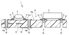
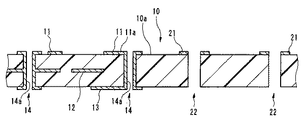
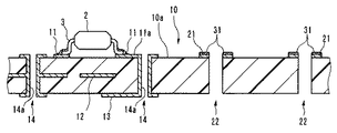
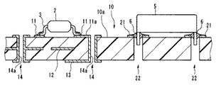
以下、本発明の実施形態について図面を参照して説明する。図1は回路基板の構成を模式的に表す断面図である。図2は、回路基板の製造方法のフローチャートである。図3は、プリント配線基板の構成を模式的に表す断面図である。図4から図7は、回路基板の製造方法を工程をおって示す説明図である。図8は、挿入部品用ランドの形状と半田印刷マスクの開口部の形状を示す斜視図である。図9は、挿入部品用ランドへの半田の印刷範囲を示す平面図である。なお、以下の説明に用いた各図においては、各部材を図面上で認識可能な程度の大きさとするため、各部材毎に縮尺を異ならせてある。 Embodiments of the present invention will be described below with reference to the drawings. FIG. 1 is a cross-sectional view schematically showing the configuration of a circuit board. FIG. 2 is a flowchart of a circuit board manufacturing method. FIG. 3 is a cross-sectional view schematically showing the configuration of the printed wiring board. 4 to 7 are explanatory views showing a method of manufacturing a circuit board through steps. FIG. 8 is a perspective view showing the shape of the insertion component land and the shape of the opening of the solder printing mask. FIG. 9 is a plan view showing a printing range of solder on the insertion component land. In each drawing used for the following description, the scale is different for each member in order to make each member a size that can be recognized on the drawing.
図1に示すように、本実施形態の回路基板1は、表面実装部品2と挿入部品(ディスクリート部品)5が同一のプリント配線基板10に半田付けにより実装されて構成されるものである。表面実装部品2は、例えばチップ状の抵抗、コンデンサ及びダイオードや多ピンのIC等がある。また、挿入部品5は、例えばパワートランジスタやコネクタ等の比較的大型の部品や、複数の部品からなり所定の機能を有する回路を構成するパッケージ(モジュール)部品等がある。なお、本実施形態では、表面実装部品2と挿入部品5の種類は以上に挙げた例に限られるものではないことは言うまでもない。また、以下の説明においては、表面実装部品2と挿入部品5を、機能に関係なく、実装方法の差異のみで区別して称するものとする。
As shown in FIG. 1, the circuit board 1 of this embodiment is configured by mounting a surface mounting component 2 and an insertion component (discrete component) 5 on the same printed
プリント配線基板10は、図3に示すように、銅箔等からなる複数の配線パターン11a、13及び13が積層された、いわゆる多層プリント配線基板であり、各配線パターン11a、12及び13は、スルーホール14の内周壁面部に形成された導体のめっき層14aにより電気的に接続されているものである。
As shown in FIG. 3, the printed
プリント配線基板10の一方の主面である実装面10a上には、第1のランドである表面実装用ランド11及び第2のランドである挿入部品用ランド21が形成されている。表面実装用ランド11及び挿入部品用ランド21は、配線パターン11aを構成する導体層のうち、ソルダーレジストにより被覆されておらず、それぞれ表面実装部品2のリード部3及び挿入部品5のリード部6が半田付けされる領域のことである。
On a
また、本実施形態のプリント配線基板10では、挿入部品用ランド21は実装面10a上にのみ形成されている。すなわち、本実施形態では、挿入部品5のリード部6が挿入される貫通孔22の内周壁面部上には、スルーホール14の構造とは異なり、導体からなる層が形成されていないのである。
Moreover, in the printed
上述した構成を有するプリント配線基板10に、表面実装部品2及び挿入部品5を実装し、回路基板1を製造する工程について、図2に示すフローチャートと図4から図9を参照して以下に説明する。プリント配線基板10の製造については、公知の多層基板の製造方法により実施されるものであるためその説明は省略するものとする。
A process of manufacturing the circuit board 1 by mounting the surface mounting component 2 and the
まず、図4に示すように、スクリーン印刷機により、プリント配線基板10の実装10a上に形成された表面実装用ランド11上及び挿入部品用ランド21上に、クリーム半田(半田ペーストとも称する)30を印刷する(ステップS01)。スクリーン印刷機は、半田印刷マスク40に形成された所定の形状の開口部を介して、クリーム半田30を表面実装用ランド11上及び挿入部品用ランド21上に供給する装置である。
First, as shown in FIG. 4, cream solder (also referred to as solder paste) 30 is formed on the
ここで、本実施形態においては、図8に示すように、半田印刷マスク40の開口部のうちの、挿入部品用ランド21上にクリーム半田30を印刷するための挿入部品用開口部41は、複数に分割されて形成されている。
Here, in the present embodiment, as shown in FIG. 8, among the openings of the
より具体的には、半田印刷マスク40の挿入部品用開口部41は、略円形状の挿入部品用ランド21と略同一の略円形状の外周形状を有するものであるが、さらに、該開口を複数に分割する梁部42が形成されている。本実施形態では、平面視で略円形状の挿入部品用開口部41は、梁部42により周方向に三等分されるものであり、言い換えれば、挿入部品用開口部41は、3つの扇状の開口部41aから41cにより構成されているのである。
More specifically, the insertion part opening 41 of the
すなわち、ステップS01においては、挿入部品用開口部41を有する半田印刷マスク40を使用して挿入部品用ランド21上にクリーム半田30が印刷される領域は、図9の網掛けの領域に示すように、平面視で貫通孔22の周方向に複数に分割されるのである。なお、同時に印刷される表面実装用ランド11上には、従来と同様に、表面実装用ランド11と略同一の形状でクリーム半田30が印刷されるものである。
That is, in step S01, the area where the
次に、図5に示すように、表面実装機により、表面実装部品2を、クリーム半田30が印刷された状態の表面実装用ランド11上に搭載する(ステップS02)。表面実装機は、搬送されてきたプリント配線基板10の実装面10a上の所定の位置に、所定の表面実装部品2を位置決めして搭載するものである。
Next, as shown in FIG. 5, the surface mounting component 2 is mounted on the
次に、図6に示すように、リフロー装置により、表面実装部品2が搭載された状態のプリント配線基板10を、所定の時間だけ所定の温度にまで加熱し、クリーム半田30を溶解させることで、表面実装部品2を表面実装用ランド11に半田付けする(ステップS03)。
Next, as shown in FIG. 6, the printed
このステップS03のリフロー時において、挿入部品用ランド21上のクリーム半田30の同時に溶解するため、挿入部品用ランド21の表面上は半田31により被覆される。すなわち、挿入部品用ランド21は、いわゆる半田コート(半田レベラ処理)が施された状態となる。
At the time of the reflow in step S03, the
次に、図7に示すように、挿入部品5のリード部6を貫通孔22に挿入し、リード部6を挿入部品用ランド21に半田付けする(ステップS04及びS05)。
以上により、プリント配線基板10に、表面実装部品2及び挿入部品5が実装され、本実施形態の回路基板1の製造工程が終了するのである。
Next, as shown in FIG. 7, the
As described above, the surface mounting component 2 and the
上述した本実施形態の効果を以下に説明する。
本実施形態の回路基板1の製造方法においては、ステップS01のクリーム半田印刷工程において、実装部品用ランド11上と挿入部品用ランド21上とに同時にクリーム半田30を印刷する場合に、挿入部品用ランド21上には、クリーム半田30が複数の領域に分割されて印刷される。
The effect of this embodiment mentioned above is demonstrated below.
In the method of manufacturing the circuit board 1 according to the present embodiment, when the
このように、挿入部品用ランド21上に、クリーム半田30を複数の領域に分割して印刷することにより、ステップS03のリフロー工程においてクリーム半田30を溶解させた場合に、溶解した半田が表面張力によって貫通孔22を塞いでしまうように広がってしまうことがない。
As described above, the
また、本実施形態のプリント配線基板10においては、挿入部品用ランド21は、実装面10a上にのみ形成されている。すなわち、挿入部品5のリード部6が挿入される貫通孔22は、その内周壁面部上に導体からなる層が形成されていない。いわば、本実施形態のプリント配線基板10は、複数の配線パターン11a、12及び13が積層された、いわゆる多層プリント配線基板でありながら、挿入部品5が実装される領域のみは、単層のプリント配線基板のように構成されているのである。
Further, in the printed
このように、挿入部品用ランド21を、実装面10a上にのみ形成することにより、ステップS03のリフロー工程においてクリーム半田30を溶解させた場合に、溶解した半田が貫通孔22内に入り込んだとしても半田はそのまま貫通孔22を通過するため、半田が貫通孔22内に留まって貫通孔22を塞いでしまうことがない。
Thus, by forming the
したがって、本実施形態によれば、混載基板に印刷により半田を印刷して半田コートを形成する際に、挿入部品用の貫通孔を塞ぐことがないのである。 Therefore, according to the present embodiment, when the solder is printed on the mixed substrate to form the solder coat, the through hole for the insertion component is not blocked.
また、上述のように、本実施形態によれば、貫通孔22が半田により塞がれてしまうことがないため、ステップS04の挿入部品5の挿入工程において、挿入部品5のリード部6を、貫通孔22に容易かつ確実に挿入することができ、回路基板1の歩留まりを向上させることが可能となる。
Further, as described above, according to the present embodiment, since the through
さらに、本実施形態では、挿入部品用ランド21は、実装面10a上にのみ形成されているため、半田付けされた挿入部品5を容易に取り外すことが可能であり、修正作業や修理作業に必要な工数を減らすことができる。
Furthermore, in this embodiment, since the
また、本実施形態においては、表面実装部品2を実装する工程であるステップS01のクリーム半田印刷工程において、同時に挿入部品用ランド21上にクリーム半田30を印刷することにより、後のステップS03のリフロー工程において、表面実装部品2の半田付けと同時に挿入部品用ランド21上に半田コートを施すことが可能となる。すなわち、工程を増やすことなく、挿入部品用ランド21上に半田コートを施すことが可能となる。
In this embodiment, in the cream solder printing process of step S01, which is a process of mounting the surface-mounted component 2, by simultaneously printing the
このように、挿入部品用ランド21上に半田コートを施すことにより、続くステップS04及びS05の挿入部品実装工程の実施前に、挿入部品用ランド21が酸化してしまうことを防止することが可能となる。これにより、ステップS01からステップS03のいわゆる表面実装工程と、ステップS04及びS05の挿入部品実装工程との間に時間的隔たりがあったとしても、回路基板1を品質を落とすことなく製造することが可能となる。例えば、本実施形態によれば、ステップS01からステップS03のいわゆる表面実装工程とステップS04及びS05の挿入部品実装工程とを、異なる工場において行うことも可能となり、回路基板1の製造工程の設計の自由度が向上する。
As described above, by applying the solder coat on the
また、このように、表面実装部品2の半田付けと同時に挿入部品用ランド21上に半田コートを施すことにより、ステップS04及びS05の挿入部品実装工程に先立って、挿入部品用ランド21上には半田盛りが行われた状態となるため、ステップS05における挿入部品の半田付け作業の工数を減らすことが可能となる。
In addition, by applying the solder coat onto the
また、本発明は、上述した実施形態に限られるものではなく、特許請求の範囲及び明細書全体から読み取れる発明の要旨或いは思想に反しない範囲で適宜変更可能であり、そのような変更を伴う半田印刷マスク、プリント配線基板及び回路基板の製造方法もまた本発明の技術的範囲に含まれるものである。 Further, the present invention is not limited to the above-described embodiment, and can be appropriately changed without departing from the gist or concept of the invention that can be read from the claims and the entire specification. Printing masks, printed wiring boards, and circuit board manufacturing methods are also included in the technical scope of the present invention.
例えば、挿入部品のリード部の断面形状が細長の矩形状である場合、一般に挿入部品用ランド21は、図10に示すように、矩形状に形成されるものである。この場合、本発明に係る半田印刷マスク40の挿入部品用開口部41は、長手方向に分割されるように形成される。すなわち、上述のステップS01のクリーム半田印刷工程においては、細長の挿入部品用ランド21上にクリーム半田30が印刷される領域は、図11の網掛けの領域に示すように、平面視で長手方向に複数に分割されるのである。このような変形例においても、上述の実施形態と同様の効果が得られるものである。
For example, when the cross-sectional shape of the lead part of the insertion part is an elongated rectangular shape, the
1…回路基板、2…表面実装部品、5…挿入部品、10…プリント配線基板、10a…実装面、21…挿入部品用ランド、…22…貫通孔、40…半田印刷マスク、41…挿入部品用開口部、42…梁部。 DESCRIPTION OF SYMBOLS 1 ... Circuit board, 2 ... Surface mounting component, 5 ... Insertion component, 10 ... Printed wiring board, 10a ... Mounting surface, 21 ... Land for insertion component, ... 22 ... Through-hole, 40 ... Solder printing mask, 41 ... Insertion component Opening, 42... Beam.
Claims (4)
前記挿入部品が半田付けされるランドに対応する開口部は、梁部が形成されることにより複数に分割されてなることを特徴とする半田印刷マスク。 A solder printing mask for printing cream solder on a printed wiring board on which a surface mounting component and an insertion component are mounted,
An opening corresponding to a land to which the insertion component is soldered is divided into a plurality of portions by forming a beam portion.
前記挿入部品が半田付けされる前記ランドを構成する導体部は、前記実装面上にのみに配設されることを特徴とするプリント配線基板。 A printed wiring board having a wiring pattern of a plurality of layers, wherein a land on which a surface mounting component and an insertion component are soldered is formed on a mounting surface,
The printed wiring board according to claim 1, wherein the conductor portion constituting the land to which the insertion component is soldered is disposed only on the mounting surface.
前記表面実装部品が半田付けされる第1のランド上に半田ペーストを印刷するとともに、前記挿入部品が半田付けされる第2のランド上に前記半田ペーストが複数の領域に分割されて印刷されるように印刷する工程と、
前記半田ペーストが印刷された第1のランド上に、前記表面実装部品を搭載する工程と、
前記基板を加熱して前記表面実装部品を前記第1のランドに半田付けするとともに、前記第2のランド上に半田による被膜を形成する工程と、
前記挿入部品を前記第2のランドに半田付けする工程とを具備することを特徴とする回路基板の製造方法。 A circuit board manufacturing method in which a surface mounting component and an insertion component are mounted on a mounting surface which is at least one main surface of a printed wiring board,
A solder paste is printed on a first land to which the surface mount component is soldered, and the solder paste is divided into a plurality of regions and printed on a second land to which the insert component is soldered. And printing process,
Mounting the surface-mounted component on the first land on which the solder paste is printed;
Heating the substrate to solder the surface-mounted component to the first land, and forming a solder film on the second land;
Soldering the insertion part to the second land. A method of manufacturing a circuit board, comprising:
前記第2のランドを構成する導体部は、前記実装面上にのみに配設されることを特徴とする請求項3に記載の回路基板の製造方法。 The printed wiring board has a wiring pattern of a plurality of layers,
The method for manufacturing a circuit board according to claim 3, wherein the conductor portion constituting the second land is disposed only on the mounting surface.
Priority Applications (1)
| Application Number | Priority Date | Filing Date | Title |
|---|---|---|---|
| JP2006350652A JP2008166310A (en) | 2006-12-26 | 2006-12-26 | Solder printing mask, printed wiring board, and circuit board manufacturing method |
Applications Claiming Priority (1)
| Application Number | Priority Date | Filing Date | Title |
|---|---|---|---|
| JP2006350652A JP2008166310A (en) | 2006-12-26 | 2006-12-26 | Solder printing mask, printed wiring board, and circuit board manufacturing method |
Publications (1)
| Publication Number | Publication Date |
|---|---|
| JP2008166310A true JP2008166310A (en) | 2008-07-17 |
Family
ID=39695447
Family Applications (1)
| Application Number | Title | Priority Date | Filing Date |
|---|---|---|---|
| JP2006350652A Pending JP2008166310A (en) | 2006-12-26 | 2006-12-26 | Solder printing mask, printed wiring board, and circuit board manufacturing method |
Country Status (1)
| Country | Link |
|---|---|
| JP (1) | JP2008166310A (en) |
Cited By (4)
| Publication number | Priority date | Publication date | Assignee | Title |
|---|---|---|---|---|
| EP2139056A1 (en) | 2008-06-25 | 2009-12-30 | Sony Corporation | Female connector structure, male connector structure, battery, adaptor and electric device |
| JP2011082498A (en) * | 2009-10-07 | 2011-04-21 | Samsung Electro-Mechanics Co Ltd | Mask for printing solder and method of manufacturing printed circuit board using the same |
| CN113455112A (en) * | 2019-02-25 | 2021-09-28 | 三菱电机株式会社 | Circuit board, semiconductor device, power conversion device, and moving object |
| CN115103528A (en) * | 2022-06-20 | 2022-09-23 | 珠海景旺柔性电路有限公司 | Flexible circuit board connector welding method and flexible circuit board |
Citations (2)
| Publication number | Priority date | Publication date | Assignee | Title |
|---|---|---|---|---|
| JPH09162536A (en) * | 1995-12-06 | 1997-06-20 | Sony Corp | Method for mounting components on printed circuit board, components mounted on printed circuit board, and printed circuit board |
| JP2002185116A (en) * | 2000-12-18 | 2002-06-28 | Rb Controls Co | Metal mask and cream solder printing method |
-
2006
- 2006-12-26 JP JP2006350652A patent/JP2008166310A/en active Pending
Patent Citations (2)
| Publication number | Priority date | Publication date | Assignee | Title |
|---|---|---|---|---|
| JPH09162536A (en) * | 1995-12-06 | 1997-06-20 | Sony Corp | Method for mounting components on printed circuit board, components mounted on printed circuit board, and printed circuit board |
| JP2002185116A (en) * | 2000-12-18 | 2002-06-28 | Rb Controls Co | Metal mask and cream solder printing method |
Cited By (4)
| Publication number | Priority date | Publication date | Assignee | Title |
|---|---|---|---|---|
| EP2139056A1 (en) | 2008-06-25 | 2009-12-30 | Sony Corporation | Female connector structure, male connector structure, battery, adaptor and electric device |
| JP2011082498A (en) * | 2009-10-07 | 2011-04-21 | Samsung Electro-Mechanics Co Ltd | Mask for printing solder and method of manufacturing printed circuit board using the same |
| CN113455112A (en) * | 2019-02-25 | 2021-09-28 | 三菱电机株式会社 | Circuit board, semiconductor device, power conversion device, and moving object |
| CN115103528A (en) * | 2022-06-20 | 2022-09-23 | 珠海景旺柔性电路有限公司 | Flexible circuit board connector welding method and flexible circuit board |
Similar Documents
| Publication | Publication Date | Title |
|---|---|---|
| JP2008166310A (en) | Solder printing mask, printed wiring board, and circuit board manufacturing method | |
| JP5938953B2 (en) | Printed wiring board warpage reduction structure and circuit board manufacturing method | |
| JPH07288375A (en) | Circuit board | |
| KR20060045757A (en) | Printed wiring board, component mounting method and mounting location confirmation method | |
| US6344974B1 (en) | Printed circuit board and method of producing same | |
| JP2010103295A (en) | Method for manufacturing end surface through-hole wiring substrate | |
| JP7522973B2 (en) | Chip component mounting structure | |
| JP2007027538A (en) | Circuit board | |
| US20070089903A1 (en) | Printed circuit board | |
| JP2001102713A (en) | Pin-erecting type printed circuit board | |
| KR20090102227A (en) | Printed circuit board and manufacturing method thereof | |
| JP2008205101A (en) | Manufacturing method of electronic component mounted substrate and electronic component mounted substrate | |
| US20060038264A1 (en) | Printed circuit board | |
| JP2009060006A (en) | Soldering pallet | |
| JPH06296076A (en) | Side face electrode forming method of smd module | |
| JP2002334953A (en) | Wiring board processing method | |
| JP2001102706A (en) | Pin-erecting type printed circuit board | |
| JP2008066344A (en) | Multilayer board, and printing method of metal bonding material | |
| JP2008103547A (en) | Solder paste application method and electronic circuit board | |
| JP7427378B2 (en) | Printed board | |
| JPS5853890A (en) | Method of soldering electronic part | |
| JP2020064998A5 (en) | ||
| KR200176365Y1 (en) | Printed circuit board | |
| JP2017220574A (en) | Method of manufacturing electronic component mounting substrate, substrate, and metal mask | |
| EP2086298B1 (en) | Solder void reduction on circuit boards |
Legal Events
| Date | Code | Title | Description |
|---|---|---|---|
| A621 | Written request for application examination |
Effective date: 20091008 Free format text: JAPANESE INTERMEDIATE CODE: A621 |
|
| A977 | Report on retrieval |
Free format text: JAPANESE INTERMEDIATE CODE: A971007 Effective date: 20110301 |
|
| A131 | Notification of reasons for refusal |
Effective date: 20110308 Free format text: JAPANESE INTERMEDIATE CODE: A131 |
|
| A521 | Written amendment |
Free format text: JAPANESE INTERMEDIATE CODE: A523 Effective date: 20110420 |
|
| A131 | Notification of reasons for refusal |
Free format text: JAPANESE INTERMEDIATE CODE: A131 Effective date: 20110531 |
|
| A02 | Decision of refusal |
Effective date: 20111011 Free format text: JAPANESE INTERMEDIATE CODE: A02 |


