JP2007526096A - Stent delivery apparatus and method - Google Patents
Stent delivery apparatus and method Download PDFInfo
- Publication number
- JP2007526096A JP2007526096A JP2007502027A JP2007502027A JP2007526096A JP 2007526096 A JP2007526096 A JP 2007526096A JP 2007502027 A JP2007502027 A JP 2007502027A JP 2007502027 A JP2007502027 A JP 2007502027A JP 2007526096 A JP2007526096 A JP 2007526096A
- Authority
- JP
- Japan
- Prior art keywords
- stent
- sheath
- expansion member
- segments
- catheter
- Prior art date
- Legal status (The legal status is an assumption and is not a legal conclusion. Google has not performed a legal analysis and makes no representation as to the accuracy of the status listed.)
- Pending
Links
Images


Classifications
-
- A—HUMAN NECESSITIES
- A61—MEDICAL OR VETERINARY SCIENCE; HYGIENE
- A61F—FILTERS IMPLANTABLE INTO BLOOD VESSELS; PROSTHESES; DEVICES PROVIDING PATENCY TO, OR PREVENTING COLLAPSING OF, TUBULAR STRUCTURES OF THE BODY, e.g. STENTS; ORTHOPAEDIC, NURSING OR CONTRACEPTIVE DEVICES; FOMENTATION; TREATMENT OR PROTECTION OF EYES OR EARS; BANDAGES, DRESSINGS OR ABSORBENT PADS; FIRST-AID KITS
- A61F2/00—Filters implantable into blood vessels; Prostheses, i.e. artificial substitutes or replacements for parts of the body; Appliances for connecting them with the body; Devices providing patency to, or preventing collapsing of, tubular structures of the body, e.g. stents
- A61F2/82—Devices providing patency to, or preventing collapsing of, tubular structures of the body, e.g. stents
- A61F2/86—Stents in a form characterised by the wire-like elements; Stents in the form characterised by a net-like or mesh-like structure
- A61F2/90—Stents in a form characterised by the wire-like elements; Stents in the form characterised by a net-like or mesh-like structure characterised by a net-like or mesh-like structure
- A61F2/91—Stents in a form characterised by the wire-like elements; Stents in the form characterised by a net-like or mesh-like structure characterised by a net-like or mesh-like structure made from perforated sheet material or tubes, e.g. perforated by laser cuts or etched holes
- A61F2/915—Stents in a form characterised by the wire-like elements; Stents in the form characterised by a net-like or mesh-like structure characterised by a net-like or mesh-like structure made from perforated sheet material or tubes, e.g. perforated by laser cuts or etched holes with bands having a meander structure, adjacent bands being connected to each other
-
- A—HUMAN NECESSITIES
- A61—MEDICAL OR VETERINARY SCIENCE; HYGIENE
- A61F—FILTERS IMPLANTABLE INTO BLOOD VESSELS; PROSTHESES; DEVICES PROVIDING PATENCY TO, OR PREVENTING COLLAPSING OF, TUBULAR STRUCTURES OF THE BODY, e.g. STENTS; ORTHOPAEDIC, NURSING OR CONTRACEPTIVE DEVICES; FOMENTATION; TREATMENT OR PROTECTION OF EYES OR EARS; BANDAGES, DRESSINGS OR ABSORBENT PADS; FIRST-AID KITS
- A61F2/00—Filters implantable into blood vessels; Prostheses, i.e. artificial substitutes or replacements for parts of the body; Appliances for connecting them with the body; Devices providing patency to, or preventing collapsing of, tubular structures of the body, e.g. stents
- A61F2/95—Instruments specially adapted for placement or removal of stents or stent-grafts
- A61F2/958—Inflatable balloons for placing stents or stent-grafts
-
- A—HUMAN NECESSITIES
- A61—MEDICAL OR VETERINARY SCIENCE; HYGIENE
- A61F—FILTERS IMPLANTABLE INTO BLOOD VESSELS; PROSTHESES; DEVICES PROVIDING PATENCY TO, OR PREVENTING COLLAPSING OF, TUBULAR STRUCTURES OF THE BODY, e.g. STENTS; ORTHOPAEDIC, NURSING OR CONTRACEPTIVE DEVICES; FOMENTATION; TREATMENT OR PROTECTION OF EYES OR EARS; BANDAGES, DRESSINGS OR ABSORBENT PADS; FIRST-AID KITS
- A61F2/00—Filters implantable into blood vessels; Prostheses, i.e. artificial substitutes or replacements for parts of the body; Appliances for connecting them with the body; Devices providing patency to, or preventing collapsing of, tubular structures of the body, e.g. stents
- A61F2/95—Instruments specially adapted for placement or removal of stents or stent-grafts
- A61F2/962—Instruments specially adapted for placement or removal of stents or stent-grafts having an outer sleeve
- A61F2/966—Instruments specially adapted for placement or removal of stents or stent-grafts having an outer sleeve with relative longitudinal movement between outer sleeve and prosthesis, e.g. using a push rod
-
- A—HUMAN NECESSITIES
- A61—MEDICAL OR VETERINARY SCIENCE; HYGIENE
- A61F—FILTERS IMPLANTABLE INTO BLOOD VESSELS; PROSTHESES; DEVICES PROVIDING PATENCY TO, OR PREVENTING COLLAPSING OF, TUBULAR STRUCTURES OF THE BODY, e.g. STENTS; ORTHOPAEDIC, NURSING OR CONTRACEPTIVE DEVICES; FOMENTATION; TREATMENT OR PROTECTION OF EYES OR EARS; BANDAGES, DRESSINGS OR ABSORBENT PADS; FIRST-AID KITS
- A61F2/00—Filters implantable into blood vessels; Prostheses, i.e. artificial substitutes or replacements for parts of the body; Appliances for connecting them with the body; Devices providing patency to, or preventing collapsing of, tubular structures of the body, e.g. stents
- A61F2/82—Devices providing patency to, or preventing collapsing of, tubular structures of the body, e.g. stents
- A61F2002/826—Devices providing patency to, or preventing collapsing of, tubular structures of the body, e.g. stents more than one stent being applied sequentially
-
- A—HUMAN NECESSITIES
- A61—MEDICAL OR VETERINARY SCIENCE; HYGIENE
- A61F—FILTERS IMPLANTABLE INTO BLOOD VESSELS; PROSTHESES; DEVICES PROVIDING PATENCY TO, OR PREVENTING COLLAPSING OF, TUBULAR STRUCTURES OF THE BODY, e.g. STENTS; ORTHOPAEDIC, NURSING OR CONTRACEPTIVE DEVICES; FOMENTATION; TREATMENT OR PROTECTION OF EYES OR EARS; BANDAGES, DRESSINGS OR ABSORBENT PADS; FIRST-AID KITS
- A61F2/00—Filters implantable into blood vessels; Prostheses, i.e. artificial substitutes or replacements for parts of the body; Appliances for connecting them with the body; Devices providing patency to, or preventing collapsing of, tubular structures of the body, e.g. stents
- A61F2/82—Devices providing patency to, or preventing collapsing of, tubular structures of the body, e.g. stents
- A61F2002/828—Means for connecting a plurality of stents allowing flexibility of the whole structure
-
- A—HUMAN NECESSITIES
- A61—MEDICAL OR VETERINARY SCIENCE; HYGIENE
- A61F—FILTERS IMPLANTABLE INTO BLOOD VESSELS; PROSTHESES; DEVICES PROVIDING PATENCY TO, OR PREVENTING COLLAPSING OF, TUBULAR STRUCTURES OF THE BODY, e.g. STENTS; ORTHOPAEDIC, NURSING OR CONTRACEPTIVE DEVICES; FOMENTATION; TREATMENT OR PROTECTION OF EYES OR EARS; BANDAGES, DRESSINGS OR ABSORBENT PADS; FIRST-AID KITS
- A61F2/00—Filters implantable into blood vessels; Prostheses, i.e. artificial substitutes or replacements for parts of the body; Appliances for connecting them with the body; Devices providing patency to, or preventing collapsing of, tubular structures of the body, e.g. stents
- A61F2/82—Devices providing patency to, or preventing collapsing of, tubular structures of the body, e.g. stents
- A61F2/86—Stents in a form characterised by the wire-like elements; Stents in the form characterised by a net-like or mesh-like structure
- A61F2/90—Stents in a form characterised by the wire-like elements; Stents in the form characterised by a net-like or mesh-like structure characterised by a net-like or mesh-like structure
- A61F2/91—Stents in a form characterised by the wire-like elements; Stents in the form characterised by a net-like or mesh-like structure characterised by a net-like or mesh-like structure made from perforated sheet material or tubes, e.g. perforated by laser cuts or etched holes
- A61F2/915—Stents in a form characterised by the wire-like elements; Stents in the form characterised by a net-like or mesh-like structure characterised by a net-like or mesh-like structure made from perforated sheet material or tubes, e.g. perforated by laser cuts or etched holes with bands having a meander structure, adjacent bands being connected to each other
- A61F2002/91508—Stents in a form characterised by the wire-like elements; Stents in the form characterised by a net-like or mesh-like structure characterised by a net-like or mesh-like structure made from perforated sheet material or tubes, e.g. perforated by laser cuts or etched holes with bands having a meander structure, adjacent bands being connected to each other the meander having a difference in amplitude along the band
-
- A—HUMAN NECESSITIES
- A61—MEDICAL OR VETERINARY SCIENCE; HYGIENE
- A61F—FILTERS IMPLANTABLE INTO BLOOD VESSELS; PROSTHESES; DEVICES PROVIDING PATENCY TO, OR PREVENTING COLLAPSING OF, TUBULAR STRUCTURES OF THE BODY, e.g. STENTS; ORTHOPAEDIC, NURSING OR CONTRACEPTIVE DEVICES; FOMENTATION; TREATMENT OR PROTECTION OF EYES OR EARS; BANDAGES, DRESSINGS OR ABSORBENT PADS; FIRST-AID KITS
- A61F2/00—Filters implantable into blood vessels; Prostheses, i.e. artificial substitutes or replacements for parts of the body; Appliances for connecting them with the body; Devices providing patency to, or preventing collapsing of, tubular structures of the body, e.g. stents
- A61F2/82—Devices providing patency to, or preventing collapsing of, tubular structures of the body, e.g. stents
- A61F2/86—Stents in a form characterised by the wire-like elements; Stents in the form characterised by a net-like or mesh-like structure
- A61F2/90—Stents in a form characterised by the wire-like elements; Stents in the form characterised by a net-like or mesh-like structure characterised by a net-like or mesh-like structure
- A61F2/91—Stents in a form characterised by the wire-like elements; Stents in the form characterised by a net-like or mesh-like structure characterised by a net-like or mesh-like structure made from perforated sheet material or tubes, e.g. perforated by laser cuts or etched holes
- A61F2/915—Stents in a form characterised by the wire-like elements; Stents in the form characterised by a net-like or mesh-like structure characterised by a net-like or mesh-like structure made from perforated sheet material or tubes, e.g. perforated by laser cuts or etched holes with bands having a meander structure, adjacent bands being connected to each other
- A61F2002/91516—Stents in a form characterised by the wire-like elements; Stents in the form characterised by a net-like or mesh-like structure characterised by a net-like or mesh-like structure made from perforated sheet material or tubes, e.g. perforated by laser cuts or etched holes with bands having a meander structure, adjacent bands being connected to each other the meander having a change in frequency along the band
-
- A—HUMAN NECESSITIES
- A61—MEDICAL OR VETERINARY SCIENCE; HYGIENE
- A61F—FILTERS IMPLANTABLE INTO BLOOD VESSELS; PROSTHESES; DEVICES PROVIDING PATENCY TO, OR PREVENTING COLLAPSING OF, TUBULAR STRUCTURES OF THE BODY, e.g. STENTS; ORTHOPAEDIC, NURSING OR CONTRACEPTIVE DEVICES; FOMENTATION; TREATMENT OR PROTECTION OF EYES OR EARS; BANDAGES, DRESSINGS OR ABSORBENT PADS; FIRST-AID KITS
- A61F2/00—Filters implantable into blood vessels; Prostheses, i.e. artificial substitutes or replacements for parts of the body; Appliances for connecting them with the body; Devices providing patency to, or preventing collapsing of, tubular structures of the body, e.g. stents
- A61F2/82—Devices providing patency to, or preventing collapsing of, tubular structures of the body, e.g. stents
- A61F2/86—Stents in a form characterised by the wire-like elements; Stents in the form characterised by a net-like or mesh-like structure
- A61F2/90—Stents in a form characterised by the wire-like elements; Stents in the form characterised by a net-like or mesh-like structure characterised by a net-like or mesh-like structure
- A61F2/91—Stents in a form characterised by the wire-like elements; Stents in the form characterised by a net-like or mesh-like structure characterised by a net-like or mesh-like structure made from perforated sheet material or tubes, e.g. perforated by laser cuts or etched holes
- A61F2/915—Stents in a form characterised by the wire-like elements; Stents in the form characterised by a net-like or mesh-like structure characterised by a net-like or mesh-like structure made from perforated sheet material or tubes, e.g. perforated by laser cuts or etched holes with bands having a meander structure, adjacent bands being connected to each other
- A61F2002/91525—Stents in a form characterised by the wire-like elements; Stents in the form characterised by a net-like or mesh-like structure characterised by a net-like or mesh-like structure made from perforated sheet material or tubes, e.g. perforated by laser cuts or etched holes with bands having a meander structure, adjacent bands being connected to each other within the whole structure different bands showing different meander characteristics, e.g. frequency or amplitude
-
- A—HUMAN NECESSITIES
- A61—MEDICAL OR VETERINARY SCIENCE; HYGIENE
- A61F—FILTERS IMPLANTABLE INTO BLOOD VESSELS; PROSTHESES; DEVICES PROVIDING PATENCY TO, OR PREVENTING COLLAPSING OF, TUBULAR STRUCTURES OF THE BODY, e.g. STENTS; ORTHOPAEDIC, NURSING OR CONTRACEPTIVE DEVICES; FOMENTATION; TREATMENT OR PROTECTION OF EYES OR EARS; BANDAGES, DRESSINGS OR ABSORBENT PADS; FIRST-AID KITS
- A61F2/00—Filters implantable into blood vessels; Prostheses, i.e. artificial substitutes or replacements for parts of the body; Appliances for connecting them with the body; Devices providing patency to, or preventing collapsing of, tubular structures of the body, e.g. stents
- A61F2/82—Devices providing patency to, or preventing collapsing of, tubular structures of the body, e.g. stents
- A61F2/86—Stents in a form characterised by the wire-like elements; Stents in the form characterised by a net-like or mesh-like structure
- A61F2/90—Stents in a form characterised by the wire-like elements; Stents in the form characterised by a net-like or mesh-like structure characterised by a net-like or mesh-like structure
- A61F2/91—Stents in a form characterised by the wire-like elements; Stents in the form characterised by a net-like or mesh-like structure characterised by a net-like or mesh-like structure made from perforated sheet material or tubes, e.g. perforated by laser cuts or etched holes
- A61F2/915—Stents in a form characterised by the wire-like elements; Stents in the form characterised by a net-like or mesh-like structure characterised by a net-like or mesh-like structure made from perforated sheet material or tubes, e.g. perforated by laser cuts or etched holes with bands having a meander structure, adjacent bands being connected to each other
- A61F2002/91533—Stents in a form characterised by the wire-like elements; Stents in the form characterised by a net-like or mesh-like structure characterised by a net-like or mesh-like structure made from perforated sheet material or tubes, e.g. perforated by laser cuts or etched holes with bands having a meander structure, adjacent bands being connected to each other characterised by the phase between adjacent bands
-
- A—HUMAN NECESSITIES
- A61—MEDICAL OR VETERINARY SCIENCE; HYGIENE
- A61F—FILTERS IMPLANTABLE INTO BLOOD VESSELS; PROSTHESES; DEVICES PROVIDING PATENCY TO, OR PREVENTING COLLAPSING OF, TUBULAR STRUCTURES OF THE BODY, e.g. STENTS; ORTHOPAEDIC, NURSING OR CONTRACEPTIVE DEVICES; FOMENTATION; TREATMENT OR PROTECTION OF EYES OR EARS; BANDAGES, DRESSINGS OR ABSORBENT PADS; FIRST-AID KITS
- A61F2/00—Filters implantable into blood vessels; Prostheses, i.e. artificial substitutes or replacements for parts of the body; Appliances for connecting them with the body; Devices providing patency to, or preventing collapsing of, tubular structures of the body, e.g. stents
- A61F2/82—Devices providing patency to, or preventing collapsing of, tubular structures of the body, e.g. stents
- A61F2/86—Stents in a form characterised by the wire-like elements; Stents in the form characterised by a net-like or mesh-like structure
- A61F2/90—Stents in a form characterised by the wire-like elements; Stents in the form characterised by a net-like or mesh-like structure characterised by a net-like or mesh-like structure
- A61F2/91—Stents in a form characterised by the wire-like elements; Stents in the form characterised by a net-like or mesh-like structure characterised by a net-like or mesh-like structure made from perforated sheet material or tubes, e.g. perforated by laser cuts or etched holes
- A61F2/915—Stents in a form characterised by the wire-like elements; Stents in the form characterised by a net-like or mesh-like structure characterised by a net-like or mesh-like structure made from perforated sheet material or tubes, e.g. perforated by laser cuts or etched holes with bands having a meander structure, adjacent bands being connected to each other
- A61F2002/9155—Adjacent bands being connected to each other
- A61F2002/91558—Adjacent bands being connected to each other connected peak to peak
Abstract
ステントを送出する装置および方法では、同じステント送出装置を使用して、治療部位を拡張すると共にステントを配置することができる。装置は通常、少なくとも1つの膨張可能な部材を有するカテーテル、その上に位置付け可能な少なくとも1つのステント、および膨張可能な部材およびステント上に配置されたシースを備える。一部の実施形態は、病変部を拡張しステントを膨張させるための別々の膨張可能な部材を備えるが、他の実施形態では両方に同じ膨張可能な部材が使用される。一部の実施形態では、ステントは複数の分離可能なステント・セグメントを含む。様々な実施形態では、自己膨張型ステントを使用することができる。方法は、ステント送出装置を治療部位に位置付け、膨張可能な部材を膨張させて治療部位で病変部の少なくとも一部を拡張し、治療部位でステントを膨張させる(または膨張することができるようにする)ことを含む。 In devices and methods for delivering stents, the same stent delivery device can be used to expand the treatment site and deploy the stent. The device typically comprises a catheter having at least one expandable member, at least one stent positionable thereon, and an expandable member and a sheath disposed on the stent. Some embodiments comprise separate inflatable members to expand the lesion and expand the stent, while in other embodiments the same inflatable member is used for both. In some embodiments, the stent includes a plurality of separable stent segments. In various embodiments, self-expanding stents can be used. The method positions the stent delivery device at the treatment site, expands the expandable member to expand at least a portion of the lesion at the treatment site, and allows the stent to expand (or expand) at the treatment site. )
Description
(関連出願の相互引用)
本出願は、2003年8月8日に出願の米国特許出願第10/637713号明細書(代理人整理番号021629−000340US)の一部継続出願である、2004年3月3日に出願の米国特許出願第10/794,405号明細書(代理人整理番号021629−002400US)の優先権を主張するものである。前記米国特許出願第10/637713号明細書は、2003年4月10日に出願の米国特許出願第10/412,714号明細書(代理人整理番号21629−000330US)の一部継続出願であり、前記米国特許出願第10/412,714号明細書は、2002年11月27日に出願の出願第10/306,813号(代理人整理番号21629−000320US)の一部継続出願であり、前記出願第10/306,813号は、2001年12月3日に出願の米国特許仮出願第60/336,767号明細書(代理人整理番号21629−000300US)および2002年3月13日に出願の第60/364,389号明細書(代理人整理番号21629−000310US)の特許出願である。上記の参考文献すべての開示を参照によりすべて本明細書に組み込む。
(Mutual citation of related applications)
This application is a continuation-in-part of US patent application Ser. No. 10/637713 filed on Aug. 8, 2003 (Attorney Docket No. 021629-000340 US), filed on Mar. 3, 2004. The priority of patent application No. 10 / 794,405 (Attorney Docket No. 021629-002400 US) is claimed. The above-mentioned US Patent Application No. 10/636713 is a continuation-in-part of US Patent Application No. 10 / 412,714 (Attorney Docket No. 21629-000330US) filed on Apr. 10, 2003. US patent application Ser. No. 10 / 412,714 is a continuation-in-part of application No. 10 / 306,813 (Attorney Docket No. 21629-000320US) filed on Nov. 27, 2002, No. 10 / 306,813 is filed on Dec. 3, 2001, US Provisional Application No. 60 / 336,767 (Attorney Docket No. 21629-000300 US) and Mar. 13, 2002. This is a patent application of application No. 60 / 364,389 (Attorney Docket No. 21629-000310US). The disclosures of all the above references are fully incorporated herein by reference.
本発明は、一般に、医療装置および方法に関する。本発明は、より詳細には、身体の管腔内に複数の管腔のプロテーゼを個別に送出するための装置および方法に関する。 The present invention generally relates to medical devices and methods. The present invention more particularly relates to an apparatus and method for individually delivering a multi-lumen prosthesis into a body lumen.
ステント技術は冠動脈疾患の患者にとってますます重要な治療の選択肢になっている。ステント技術は、冠動脈の病変部内に管状プロテーゼを配置して、動脈管腔を膨張させ、動脈の開通性を維持するものである。初期のステント技術は、冠動脈がステントの配置後に再閉鎖する傾向を指す再狭窄の問題があった。しかし近年では、ステント設計が改善され、薬物溶出ステントの開発によって再狭窄率が激減した。そのため、米国、ヨーロッパ、その他の国で行われるステント技術処置の数が急増した。 Stent technology has become an increasingly important treatment option for patients with coronary artery disease. Stent technology places a tubular prosthesis within a coronary artery lesion to dilate the arterial lumen and maintain the patency of the artery. Early stent technology had the problem of restenosis, which refers to the tendency of coronary arteries to reclose after stent placement. In recent years, however, stent design has improved and the development of drug-eluting stents has dramatically reduced the rate of restenosis. This has led to a surge in the number of stent technology procedures performed in the United States, Europe and other countries.
ステントは、通常は大腿動脈を通して挿入される長い可撓性血管カテーテルを使用して冠動脈に送られる。自己膨張型ステントでは、ステントは単に送出カテーテルから開放され、弾性的に膨張して血管壁と係合する。バルーン膨張型ステントでは、送出カテーテルのバルーンが膨張させられ、それによってステントが所望の径に膨張し、変形し、その後バルーンが縮小され除去される。 The stent is delivered to the coronary artery using a long flexible vascular catheter that is usually inserted through the femoral artery. In self-expanding stents, the stent is simply released from the delivery catheter and elastically expands to engage the vessel wall. In a balloon expandable stent, the balloon of the delivery catheter is inflated, thereby expanding and deforming the stent to the desired diameter, after which the balloon is contracted and removed.
最近のステント送出技術の多くの進歩にもかかわらず、依然としていくつかの欠点が存在する。例えば、現在のステント送出カテーテルでは、治療すべき病変部の大きさに合うようにその場でステントの長さをカスタマイズすることができない。血管造影法または蛍光透視法を使用してステント技術の前に病変部の大きさを測定することができるが、こうした測定値は不正確なことがある。ステントが導入され、そのステントが適切な大きさでないことが判明した場合、送出カテーテルとステントを患者から取り出し、正しいサイズの違う装置と取り替えなければならない。さらに、現在のステント送出装置では、単一のカテーテルで複数の病変部を治療することができない。複数の病変部を治療する場合は、治療すべき病変部ごとに新しいカテーテルとステントを導入しなければならない。 Despite many recent advances in stent delivery technology, there are still some drawbacks. For example, with current stent delivery catheters, the length of the stent cannot be customized in situ to fit the size of the lesion to be treated. Although angiography or fluoroscopy can be used to measure lesion size prior to stent technology, these measurements can be inaccurate. If a stent is introduced and it is found that the stent is not the correct size, the delivery catheter and stent must be removed from the patient and replaced with a different size device. In addition, current stent delivery devices cannot treat multiple lesions with a single catheter. When treating multiple lesions, a new catheter and stent must be introduced for each lesion to be treated.
また、現在使用可能なステント送出装置は、非常に長い、かつ/または血管の湾曲した領域の血管病変部の治療にはあまり適していない。現在のステントは、ステントが剛性なために比較的短い別個の長さを有するものである。比較的長い病変部を治療するために、こうしたステントを長く作成しても、血管の曲率、または拍動する心臓の表面上の血管の動きにうまく一致しないであろう。一方、比較的長い領域で複数のステントの端と端をつなぐことを試みても、適切なステント間の間隔を維持し、隣接するステントの重なりを防ぐことができないことが障害になる。本発明は従来技術のこうした欠点に対処するものであり、参照により本明細書にすべて組み込まれている米国特許出願第10/412714号明細書(代理人整理番号21629−000330)や、前に参照により組み込まれている第10/637713号に記載されている。 Also, currently available stent delivery devices are not well suited for the treatment of vascular lesions in very long and / or curved regions of blood vessels. Current stents have a relatively short discrete length due to the rigidity of the stent. Creating such stents to treat relatively long lesions would not match the curvature of blood vessels or the movement of blood vessels on the beating heart surface. On the other hand, even if an attempt is made to connect the ends of a plurality of stents in a relatively long region, an obstacle is that an appropriate interval between the stents cannot be maintained and overlapping of adjacent stents cannot be prevented. The present invention addresses these shortcomings of the prior art and is incorporated by reference in US patent application Ser. No. 10 / 414,714 (Attorney Docket No. 21629-000330), previously incorporated by reference. No. 10/637713, which is incorporated by reference.
上記で参照した特許出願明細書に記載された改善点に、ステント送出装置および方法のさらなる改善が求められている。例えば、冠動脈ステントが狭窄性病変部内で展開される前に、通常、医師は先ず血管形成バルーンで病変部を拡張する。こうした「予備拡張」に続いて、血管形成カテーテルを除去し、ステント送出カテーテルを治療部位に前進させてステントを展開する。上記で組み込まれた米国特許出願第10/412714号や第10/637713号に記載されたステント送出システムの著しい進歩の1つは、カテーテルを除去または再配置することなく、様々な部位の複数の病変部を治療することができることである。こうしたステント送出システムを第1の病変部に位置付けて、所望の長さの第1のステントを展開させ、次いで第2の部位に移動させ、そこに異なる長さの第2のステントを展開させることができる。これを、カテーテルを交換せずに複数の病変部に繰り返して行うことができ、それによって時間が節約され、複数のカテーテルを使用する非効率性が回避される。しかし、血管形成カテーテルを使用して病変部を予め拡張し、別のステント送出カテーテルを使用してステントを送出する必要がある場合は、こうした効率が低減される。別々の予備拡張とステント送出カテーテルが使用される場合は、ステント技術処置中に2つのカテーテルを何回も交換し、または「取り出す」ことがしばしば必要とされるであろう。 There is a need for further improvements in stent delivery devices and methods to the improvements described in the above-referenced patent application. For example, before a coronary stent is deployed within a stenotic lesion, a physician typically first dilates the lesion with an angioplasty balloon. Following such “pre-expansion”, the angioplasty catheter is removed and the stent delivery catheter is advanced to the treatment site to deploy the stent. One of the significant advancements in stent delivery systems described in the above-incorporated US patent application Ser. Nos. 10 / 41,714 and 10 / 636,713 is that multiple sites at various sites can be used without removing or repositioning the catheter. The lesion can be treated. Positioning such a stent delivery system at a first lesion, deploying a first stent of a desired length, and then moving to a second site where a second stent of a different length is deployed. Can do. This can be repeated for multiple lesions without replacing the catheter, thereby saving time and avoiding the inefficiency of using multiple catheters. However, this efficiency is reduced if the angioplasty catheter is used to pre-dilate the lesion and another stent delivery catheter needs to be delivered. If separate pre-expansion and stent delivery catheters are used, it will often be necessary to exchange or “remove” the two catheters many times during the stent technique procedure.
したがって、別々の血管形成カテーテルを必要とせずに、病変部を予め拡張するのに使用することができるステント送出システムを有することが望ましい。理想的には、こうしたステント送出システムによって、複数かつ/または長い病変部を個別に予め拡張し、こうした病変部に個別のステントを展開することができ、カテーテルの交換が不要であることが望ましい。こうしたシステムによって、ユーザが予備拡張装置の長さを調整して治療すべき病変部の長さに合わせることもできることが好ましい。本発明はこうした目的の少なくとも一部を満たすものである。 Therefore, it is desirable to have a stent delivery system that can be used to pre-dilate the lesion without the need for a separate angioplasty catheter. Ideally, such a stent delivery system would allow multiple and / or long lesions to be pre-expanded individually, deploying individual stents in such lesions, and eliminating the need for catheter replacement. Such a system preferably allows the user to adjust the length of the pre-expansion device to match the length of the lesion to be treated. The present invention satisfies at least some of these objectives.
本発明は、1つまたは複数のステントを身体の管腔内に送出する装置および方法を提供する。本発明の一態様では、少なくとも1つのステントを治療部位に送出するステント送出装置は、近位端と遠位端を有するカテーテル軸、カテーテル軸上に位置付け可能な少なくとも1つのステント、ステントの少なくとも一部を治療部位で展開させるステント展開機構、少なくとも1つのステントの展開と関係なく治療部位で病変部の少なくとも一部を拡張する拡張部材を備える。展開機構は、全般的に、ステントの展開される部分の長さをユーザが選択することができるようにする。一部の実施態様では、展開されるステントの長さをその場で選択することができる。同様に、一部の実施態様では、病変部を拡張するために膨張すべき拡張部材の長さをその場で選択することができる。 The present invention provides an apparatus and method for delivering one or more stents into a body lumen. In one aspect of the invention, a stent delivery device for delivering at least one stent to a treatment site includes a catheter shaft having a proximal end and a distal end, at least one stent positionable on the catheter shaft, and at least one of the stents. A stent deployment mechanism for deploying the site at the treatment site, and an expansion member for expanding at least a part of the lesion site at the treatment site regardless of the deployment of at least one stent. The deployment mechanism generally allows the user to select the length of the deployed portion of the stent. In some embodiments, the length of the deployed stent can be selected in situ. Similarly, in some embodiments, the length of the expansion member to be expanded to expand the lesion can be selected in situ.
一部の実施態様では、ステント展開機構は、カテーテル軸に遠位端付近で結合されたステント膨張部材と、そのステント膨張部材とその上のステントの少なくとも一部を覆って配置された少なくとも1つの軸方向に可動のシースを備える。一部の実施態様では、ステント膨張部材は拡張部材として働くこともできる。別法として、拡張部材をシースに結合させることもできる。他の実施態様では、拡張部材を、カテーテル軸内に摺動可能に配置された内部軸に結合することができる。 In some embodiments, the stent deployment mechanism includes a stent expansion member coupled to the catheter shaft near the distal end, and at least one disposed over the stent expansion member and at least a portion of the stent thereon. A sheath movable in the axial direction is provided. In some embodiments, the stent expansion member can also serve as an expansion member. Alternatively, the expansion member can be coupled to the sheath. In other embodiments, the expansion member can be coupled to an internal shaft that is slidably disposed within the catheter shaft.
一部の実施態様では、少なくとも1つのステントが複数の分離可能なステント・セグメントを含む。任意選択で、分離可能なステント・セグメントは、カテーテル軸かつ/またはステント膨張部材に対して軸方向に可動でもよい。こうした実施態様は、ステント・セグメントをカテーテル軸かつ/またはステント膨張部材に沿って前進させるプッシャー部材をさらに任意選択で備えることができる。シースを備える一部の実施態様では、上記のように、シースを、ステント膨張部材の第1の部分と第1の複数のステント・セグメントの膨張を抑制する一方、ステント膨張部材の第2の部分と第2の複数のステント・セグメントの膨張を可能にするように構成することができる。シースはさらに任意選択で、第1の複数のステント・セグメントを第2の複数のステント・セグメントから分離して、ステント・セグメントが隣接するステント・セグメントを妨害せずに膨張することができるようにする少なくとも1つの分離装置を備えることができる。 In some embodiments, the at least one stent includes a plurality of separable stent segments. Optionally, the separable stent segment may be axially movable relative to the catheter shaft and / or the stent expansion member. Such embodiments may further optionally include a pusher member that advances the stent segment along the catheter shaft and / or the stent expansion member. In some embodiments comprising a sheath, as described above, the sheath inhibits expansion of the first portion of the stent expansion member and the first plurality of stent segments while the second portion of the stent expansion member. And a second plurality of stent segments can be configured to allow expansion. The sheath is further optionally separates the first plurality of stent segments from the second plurality of stent segments so that the stent segments can expand without interfering with adjacent stent segments. At least one separation device.
一部の実施態様では、拡張部材とステント膨張部材は独立して膨張可能でもよい。こうした実施態様は、任意選択でさらに、拡張部材を膨張させるための少なくとも1つの膨張管腔を備えることができる。例えば、一部の実施態様では、膨張管腔は、拡張部材に結合されたシース上に同心状に配置された管状部材を備えることができる。代替実施態様では、膨張管腔は、拡張部材に結合されたシースの外面に結合され、それに沿って延びる管状部材を備えることができる。他の実施態様では、膨張管腔を、拡張部材に結合されたシースの壁内に配置することができる。 In some embodiments, the expansion member and the stent expansion member may be independently expandable. Such embodiments may optionally further comprise at least one inflation lumen for inflating the expansion member. For example, in some implementations, the inflation lumen can comprise a tubular member disposed concentrically on a sheath coupled to the expansion member. In an alternative embodiment, the inflation lumen can comprise a tubular member coupled to and extending along the outer surface of the sheath coupled to the expansion member. In other embodiments, the inflation lumen can be disposed within the wall of the sheath coupled to the expansion member.
本発明の他の態様では、少なくとも1つのステントを治療部位に送出するステント送出装置は、近位端と遠位端を有するカテーテル軸、カテーテル軸に遠位端付近で結合された膨張可能な部材、膨張可能な部材上に摺動可能に位置付け可能な少なくとも1つのステント、膨張可能な部材とその上のステントの少なくとも一部を覆って配置される少なくとも1つの軸方向に可動のシースを備える。全般的に、シースは、ステントを露出せずに膨張可能な部材の少なくとも一部を露出させるようにカテーテル本体に対して軸方向に可動であり、ステントが膨張することができるようにステントの少なくとも一部を露出させるようにも可動である。 In another aspect of the invention, a stent delivery device for delivering at least one stent to a treatment site includes a catheter shaft having a proximal end and a distal end, an inflatable member coupled to the catheter shaft near the distal end. At least one stent slidably positioned on the expandable member, and at least one axially movable sheath disposed over the expandable member and at least a portion of the stent thereon. In general, the sheath is moveable axially relative to the catheter body to expose at least a portion of the expandable member without exposing the stent, and at least the stent so that the stent can expand. It is also movable to expose a part.
一部の実施態様では、ステントは自己膨張型である。例えば、一部の実施態様では、ステントは、複数の分離可能な自己膨張型のステント・セグメントを含む。一部の実施態様では、ステント(あるいは1つまたは複数のステント・セグメント)をプッシャー部材によって膨張可能な部材に沿って前進させることができる。任意選択で、シースを、第1の複数のステント・セグメントの膨張を抑制し、第2の複数のステント・セグメントの膨張を可能にするように構成することができる。一部の実施態様では、シースはさらに、第1の複数のステント・セグメントを第2の複数のステント・セグメントから分離して、ステント・セグメントが隣接するステント・セグメントを妨害せずに膨張することができるようにする少なくとも1つの分離装置を備えることができる。様々な実施態様では、ステント・セグメントは任意の適した形状記憶材料などを含むことができる。例えば、一実施態様では、ステント・セグメントは熱形状記憶材料を含み、膨張可能な部材は1つまたは複数の加熱または冷却された流体を受け入れてステント・セグメントの温度を変えるように構成される。 In some embodiments, the stent is self-expanding. For example, in some embodiments, the stent includes a plurality of separable self-expanding stent segments. In some embodiments, the stent (or one or more stent segments) can be advanced along the expandable member by a pusher member. Optionally, the sheath can be configured to inhibit expansion of the first plurality of stent segments and to allow expansion of the second plurality of stent segments. In some embodiments, the sheath further separates the first plurality of stent segments from the second plurality of stent segments so that the stent segments expand without interfering with adjacent stent segments. There may be provided at least one separation device that allows In various embodiments, the stent segment can include any suitable shape memory material and the like. For example, in one embodiment, the stent segment includes a thermal shape memory material and the expandable member is configured to receive one or more heated or cooled fluids to change the temperature of the stent segment.
本発明の他の態様では、血管内の標的部位を治療するためのステント送出装置は、近位端と遠位端を有するカテーテル軸、カテーテル軸上に設けられ、カテーテル軸から展開可能な第1のステント、カテーテル軸上で搬送され第1のステントとは関係なくカテーテル軸から展開可能な第2のステント、第1と第2のステントの展開と関係なく標的部位を拡張するための拡張部材を備える。 In another aspect of the present invention, a stent delivery apparatus for treating a target site in a blood vessel includes a catheter shaft having a proximal end and a distal end, a first provided on the catheter shaft and deployable from the catheter shaft. A second stent that is transported on the catheter shaft and deployable from the catheter shaft regardless of the first stent, and an expansion member for expanding the target site regardless of the deployment of the first and second stents. Prepare.
本発明の他の態様では、少なくとも1つのステントを治療部位に送出するステント送出装置は、近位端と遠位端を有するカテーテル軸、カテーテル軸に遠位端付近で結合されたステント膨張部材、ステント膨張部材上に位置付け可能な少なくとも1つのステント、ステント膨張部材とその上のステントの少なくとも一部を覆って配置された少なくとも1つの軸方向に可動のシース、さらには治療部位で1つまたは複数の病変部を拡張させるためのシースに結合された拡張部材を備える。ステントはやはり、複数の分離可能なステント・セグメントを含むことができ、ステント・セグメントは任意選択でステント膨張部材に対して軸方向に可動でもよい。こうした実施態様は、ステント・セグメントを前進させるためのプッシャー部材を備えこともできる。シースと膨張可能な部材は、上記の任意の特徴を有することができる。 In another aspect of the invention, a stent delivery device for delivering at least one stent to a treatment site includes a catheter shaft having a proximal end and a distal end, a stent expansion member coupled to the catheter shaft near the distal end, At least one stent positionable on the stent expansion member, at least one axially movable sheath disposed over the stent expansion member and at least a portion of the stent thereon, and one or more at the treatment site An expansion member coupled to a sheath for expanding the lesion. The stent may also include a plurality of separable stent segments, which may optionally be movable axially relative to the stent expansion member. Such embodiments may also include a pusher member for advancing the stent segment. The sheath and the inflatable member can have any of the features described above.
本発明の他の態様では、少なくとも1つのステントを治療部位に送出するステント送出装置は、近位端と遠位端を有するカテーテル軸、カテーテル軸上に位置付け可能な少なくとも1つのステント、カテーテル軸とステントを覆って配置された少なくとも1つの軸方向に可動のシース、カテーテル軸内に摺動可能に配置された内部軸、治療部位で1つまたは複数の病変部を拡張させるための内部軸の遠位端に結合された拡張部材を備える。一部の実施態様では、ステントは、複数の分離可能なステント・セグメントを含み、ステント・セグメントは任意選択でステント膨張部材に対して軸方向に可動でもよい。こうした一実施態様は、ステント・セグメントを前進させるためのプッシャー部材を備えることもできる。シースと膨張可能な部材は、上記の任意の特徴を有することができる。 In another aspect of the invention, a stent delivery apparatus for delivering at least one stent to a treatment site includes a catheter shaft having a proximal end and a distal end, at least one stent positionable on the catheter shaft, a catheter shaft, At least one axially movable sheath disposed over the stent, an internal shaft slidably disposed within the catheter shaft, and distant from the internal shaft for dilating one or more lesions at the treatment site An expansion member coupled to the distal end. In some embodiments, the stent includes a plurality of separable stent segments, which may optionally be axially movable relative to the stent expansion member. One such embodiment may also include a pusher member for advancing the stent segment. The sheath and the inflatable member can have any of the features described above.
一部の実施態様では、内部軸は、管状のカテーテル軸を備える。別法として、内部軸は案内ワイヤを備えることもできる。一部の実施態様では、内部軸は、拡張部材の少なくとも一部をカテーテル軸の遠位端から外に露出させるように摺動可能であり、内部軸は拡張部材を少なくとも部分的にカテーテル軸内の位置に引き込めるように摺動可能である。一部の実施態様では、拡張部材は、カテーテル軸の遠位端から一部だけを露出させながら膨張可能である。一部の実施態様では、拡張部材は拡張部材の露出される部分の長さを調整して、治療部位で所望の長さの病変部を拡張するように、カテーテル軸に対して位置付け可能である。 In some embodiments, the internal shaft comprises a tubular catheter shaft. Alternatively, the inner shaft can comprise a guide wire. In some embodiments, the inner shaft is slidable to expose at least a portion of the expansion member out of the distal end of the catheter shaft, the inner shaft at least partially within the catheter shaft. It is slidable to be retracted to the position. In some embodiments, the expansion member is inflatable while only exposing a portion from the distal end of the catheter shaft. In some embodiments, the dilation member can be positioned relative to the catheter shaft to adjust the length of the exposed portion of the dilation member to dilate the desired length of the lesion at the treatment site. .
任意選択で、ステント膨張部材と拡張部材の一方または両方を膨張させるために、個別の膨張管腔を備えることができる。一部の実施態様では、拡張部材を膨張させるために個別の管腔を備える場合、膨張管腔は、内部軸上に同心状に配置された管状部材を備える。別法として、膨張管腔は内部軸内に配置された管状部材を備えることもできる。他の実施態様では、膨張管腔を、内部軸の壁内に配置することができる。 Optionally, a separate inflation lumen can be provided to inflate one or both of the stent expansion member and the expansion member. In some embodiments, where a separate lumen is provided to inflate the expansion member, the expansion lumen comprises a tubular member disposed concentrically on the internal axis. Alternatively, the inflation lumen can comprise a tubular member disposed within the internal shaft. In other embodiments, the inflation lumen can be disposed within the wall of the inner shaft.
本発明の他の態様では、少なくとも1つのステントを治療部位に送出する方法は、ステント送出カテーテル装置の遠位端を治療部位に位置付けること、ステント送出カテーテルが少なくとも1つのステントを運ぶこと、カテーテル装置上で膨張可能な部材の少なくとも一部を膨張させて治療部位で病変部の少なくとも一部を拡張すること、選択した長さを有するステントの展開可能な部分を選択すること、治療部位でステントの展開可能な部分を膨張させ、ステントの配置されない部分を送出カテーテル内に残留させることを含む。一部の実施態様は、任意選択でさらに、ステントの展開可能な部分を膨張可能な部材上に位置付けることを含んでもよい。一部の実施態様は、任意選択でさらに、ステントの展開可能な部分の膨張が膨張可能な部材を膨張させることを含む。一部の実施態様では、少なくとも1つのステントが複数のステント・セグメントを含み、シースを引き込めることによって、ステント・セグメントの少なくとも1つが露出して治療部位で自己膨張する。こうした実施態様は、任意選択でさらに、シースを引き込めた後に、膨張可能な部材を少なくとも1つの自己膨張型ステント・セグメント内に位置付けること、および膨張可能な部材の少なくとも一部を膨張させてステント・セグメントをさらに膨張させることを含むことができる。 In another aspect of the invention, a method of delivering at least one stent to a treatment site includes positioning a distal end of the stent delivery catheter device at the treatment site, the stent delivery catheter carrying at least one stent, a catheter device Expanding at least a portion of the lesion at the treatment site by expanding at least a portion of the expandable member above, selecting an expandable portion of the stent having a selected length, and Inflating the deployable portion and leaving the undeployed portion of the stent in the delivery catheter. Some embodiments may optionally further include positioning the deployable portion of the stent on the expandable member. Some embodiments optionally further include expanding the expandable portion of the stent to expand the expandable member. In some embodiments, the at least one stent includes a plurality of stent segments and retracting the sheath causes at least one of the stent segments to be exposed and self-expanded at the treatment site. Such embodiments optionally further include positioning the expandable member within the at least one self-expanding stent segment and retracting at least a portion of the expandable member after retracting the sheath. -It can include further expanding the segment.
一部の実施態様では、この方法は、膨張ステップの前に、膨張可能な部材の一部をシースの外に露出させることも含むことができる。この方法は、さらに任意選択で、膨張ステップの後に、膨張可能な部材の一部をシース内の位置に引き込めることも含むことができる。一部の実施態様は、ステント・セグメントが膨張可能な部材上に配置されている間に膨張可能な部材に流体を通過させ、ステント・セグメントが熱形状記憶材料を含み、流体を流すことによってステント・セグメントの温度を変えることを含むことができる。例えば、一部の実施態様では、通過される流体が体温よりも高くなるように加熱され、他の実施態様では、体温よりも低くなるように冷却される。一部の実施態様では、膨張可能な部材の一部が流体を使用して膨張される。 In some embodiments, the method can also include exposing a portion of the expandable member out of the sheath prior to the expansion step. The method may further optionally include retracting a portion of the inflatable member to a position within the sheath after the inflation step. Some embodiments allow a fluid to pass through the expandable member while the stent segment is disposed on the expandable member, the stent segment includes a thermal shape memory material, and the fluid flows. Can include changing the temperature of the segment. For example, in some embodiments, the fluid being passed is heated to be above body temperature, and in other embodiments, it is cooled to be below body temperature. In some embodiments, a portion of the inflatable member is inflated using a fluid.
本発明の他の態様では、少なくとも1つのステントを治療部位に送出する方法は、ステント送出カテーテル装置の遠位部分を治療部位に位置付けること、ステント送出カテーテルが少なくとも1つのステントを搬送すること、カテーテル装置の拡張部材の少なくとも一部を膨張させて治療部位で病変部の少なくとも一部を拡張すること、カテーテル装置のステント膨張部材の少なくとも一部を拡張させて治療部位に少なくとも1つのステントの少なくとも一部を展開させることを含む。この方法は、さらに任意選択で、ステントの展開可能な部分を選択し、展開可能な部分がステント膨張部材によって膨張され、ステントの展開されない部分が膨張せずにステント送出カテーテル内に残留することを含むことができる。やはり一部の実施態様では、少なくとも1つのステントが複数のステント・セグメントを含み、少なくとも一部を展開することが、ステント・セグメントの少なくとも1つを展開することを含む。 In another aspect of the invention, a method of delivering at least one stent to a treatment site includes positioning a distal portion of a stent delivery catheter device at the treatment site, the stent delivery catheter carrying at least one stent, a catheter Expanding at least a portion of the lesion at the treatment site by expanding at least a portion of the expansion member of the device; expanding at least a portion of the stent expansion member of the catheter device to at least one of the at least one stent at the treatment site; Including deploying parts. The method further optionally selects a deployable portion of the stent, the expandable portion is expanded by the stent expansion member, and the undeployed portion of the stent remains unexpanded in the stent delivery catheter. Can be included. Again, in some embodiments, the at least one stent includes a plurality of stent segments, and deploying at least a portion includes deploying at least one of the stent segments.
一部の実施態様では、拡張部材は、ステントとステント膨張部材上に摺動可能に配置されたシースの外面上に配置される。こうした実施態様では、方法は、シースを引き込めて、ステント膨張部材の少なくとも一部と少なくとも1つのステントを露出させることを含むこともできる。代替実施態様はさらに、カテーテル装置の内部軸をステント膨張部材に対して遠位に摺動して、拡張部材の少なくとも一部を露出させ、拡張部材が内部軸上に配置されることを含むことができる。一部の実施態様では、こうした方法は、カテーテル本体を内部軸上で遠位に摺動して、ステント膨張部材を治療部位に位置付けることを含むこともできる。任意選択で、ステントが展開された後に、次いで拡張部材を治療部位で再膨張させることを含むことができる。 In some embodiments, the expansion member is disposed on the outer surface of a sheath that is slidably disposed on the stent and the stent expansion member. In such embodiments, the method can also include retracting the sheath to expose at least a portion of the stent expansion member and at least one stent. Alternative embodiments further include sliding the internal shaft of the catheter device distally with respect to the stent expansion member to expose at least a portion of the expansion member, the expansion member being disposed on the internal shaft. Can do. In some implementations, such methods can also include sliding the catheter body distally on the internal shaft to position the stent expansion member at the treatment site. Optionally, after the stent has been deployed, the expansion member can then be re-expanded at the treatment site.
本発明の特質および利点のさらなる側面が、添付の図面と併せて、以下の詳細な説明から明らかになるであろう。 Further aspects of the nature and advantages of the present invention will become apparent from the following detailed description, taken in conjunction with the accompanying drawings.
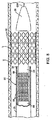
本発明によるステント送出カテーテルの一実施形態を図1で示す。ステント送出カテーテル20は、内部軸27上に摺動可能に配置された外側シース25を備えるカテーテル本体22を含む。膨張可能な部材24は、好ましくは(膨張した構成で示されている)膨張可能なバルーンであるが、内部軸27に取り付けられ、シース25を内部軸27に対して引き込めることによって露出される。テーパを付けたノーズ・コーン28は、装置の前進中に血管に損傷を与えるのを低減するために柔軟な弾性材料から構成されており、膨張可能な部材24の遠位に取り付けられている。ステント30が、好ましくは複数の個別のまたは分離可能なステント・セグメント32を含み、膨張可能な部材24上に配置されて膨張可能な部材24と共に膨張するようになっている。案内ワイヤ管34は、膨張可能な部材24の近くにあるシース25内の案内ワイヤ管出口ポート35を通って摺動可能に位置付けられる。案内ワイヤ36は案内ワイヤ管34、膨張可能な部材24、ノーズ・コーン28を通って摺動可能に位置付けられ、ノーズ・コーン28の遠位に延びる。
One embodiment of a stent delivery catheter according to the present invention is shown in FIG.
ハンドル38は、シース25の近位端23に取り付けられ、以下に記載する目的で、ハンドル38に摺動可能に取り付けられたアクチュエータ40を備える。アダプタ42はハンドル38の近位端に取り付けられ、カテーテル・ポート44を備え、このカテーテル・ポート44を通って内部軸27が摺動可能に位置付けられる。フラッシュ・ポート48はアダプタ42の側面に取り付けられており、フラッシュ・ポート48を通って食塩水など流体をカテーテル本体22の内部に導入することができる。カテーテル・ポート44内の環状シール(図示せず)は、内部軸27の周囲を密封して、流体がカテーテル・ポート44を通る漏れを防止する。任意選択で、ねじ付きカラーなどクランプ(図示せず)をカテーテル・ポート44に取り付けて、内部軸27をハンドル38に対して係止させることができる。
The
内部軸27は近位端50を有し、この近位端50に膨張アダプタ52が取り付けられる。膨張アダプタ52は膨張装置54と流体的に結合されるように構成される。膨張装置54は、Santa Clara、CAのAdvanced Cardiovascular Systemsから入手可能な「Indeflator(商標)」で販売されているものなど、市販のバルーン膨張装置でもよい。膨張アダプタ52は、内部軸27内の(以下に記載する)膨張管腔を介して膨張可能な部材24と流体連通して、膨張可能な部材24を膨張することができるようになっている。
The
次に図2A〜2B、3、4を参照すると、ステント送出カテーテルの遠位部分が断面図で示されている。図で分かるように、シース25をノーズ・コーン28まで引き延ばして、膨張可能な部材24とステント・セグメント32を完全に取り囲んでいる状態が示されている。シース25の位置を見やすくするために、蛍光透視法を使用して1つまたは複数の放射線不透過性マーカ56がシース25の遠位端57付近に取り付けられている。好ましい一実施形態では、2つの環状マーカ56が、より詳細に以下に記載する目的で、ステント・セグメント32の1つの長さに等しい長さだけ間隔をおいて配置されている。シース25はさらに弁部材58を備える。弁部材58は、遠位端57から近位方向にステント・セグメント32の1つの長さと等しい距離だけ間隔をおいて配置されることが好ましい。弁部材58は、内側に延びるフランジ60を有する。フランジ60は、ステント・セグメント32と摩擦係合するように構成され、それによってステント・セグメント32がシース25に対して遠位に摺動するのを制限する。フランジ60は、シース25と一体的に形成されたポリマー材料、またはシース25に接着あるいは他の方法で取り付けられた別の環状部材でもよい。弁部材58の様々な実施形態が、参照により本明細書に組み込まれている、同時継続中の、2003年4月10日に出願された出願第10/412,714号明細書(代理人整理番号21629−000330)に記載されている。
2A-2B, 3, and 4, the distal portion of the stent delivery catheter is shown in cross-section. As can be seen, the
シース25は、非膨張構成の場合に、膨張可能な部材24とその膨張可能な部材24の上に配置されたステント・セグメント32を取り囲むように構成された遠位端部62を有する。遠位端部62は接合部63まで近位方向に延び、接合部63は好ましくは案内ワイヤ管出口ポート35の位置と位置合わせされており、接合部63で遠位端部62は近位端部64に接合され、近位端部64はハンドル38(図1を参照)まで近位方向に延びている。好ましい一実施形態では、遠位端部62の長さは約15〜35cmであり、近位端部64の長さは約100〜125cmである。近位端部64を様々な生態親和性のポリマー、または金属、好ましくはステンレス鋼またはニチノールから構成することができる。遠位端部62は、PTFE、FEP、ポリイミド、またはPebaxなどポリマーでもよく、好ましくは金属またはポリマーの網組で補強して、膨張可能な部材24が膨張するときに半径方向の膨張に抵抗するようにする。
The
好ましくは、近位端部64は遠位端部62よりも径を小さくして、血管腔内で案内ワイヤ管34の追加される幅に対応させる他に、可撓性を最大に、断面を最小にする。一実施形態では、図3で示したように、遠位端部62は、好ましくは約1.0〜1.5mmの第1の外径を有する管状部材であり、近位端部64は、好ましくは約0.7〜1.0mmの第2の比較的小さい外径を有する管状部材である。近位端部64と遠位端部62の接合部に、近位に面した三日月形の開口65が2つの管状部材の間に形成され、案内ワイヤ管出口ポート35が作成される。三日月形開口65内の余剰空間を接着剤など充填剤で充填することができる。
Preferably, the
代替実施形態(図示せず)では、遠位端部62または近位端部64の側壁に穴が形成されて、案内ワイヤ管出口ポート35が作成される。案内ワイヤ管34に隣接するシース25の壁は、案内ワイヤ管出口ポート35の近位で平坦化され、すなわち内側につぶすことができるようになっており、それによって案内ワイヤ管34の幅に順応するようにシース25の径が縮小される。
In an alternative embodiment (not shown), a hole is formed in the sidewall of the
案内ワイヤ管34は案内ワイヤ管出口ポート35を通って摺動可能に位置付けられる。案内ワイヤ管出口ポート35は、案内ワイヤ管34の周囲に完全なまたは部分的な液封を形成して、シース25の内部への血流を制限し、食塩水(または他のフラッシュ用流体)がシース25の外に漏れるのを制限するように構成されることが好ましい。これは、案内ワイヤ管出口ポート35を適切なサイズにして、案内ワイヤ管34の周囲にきっちりした摩擦シールを形成しながらも、案内ワイヤ管34がシース25に対して摺動することができるようにすることによって実施される。別法として、環状シーリング・リングを案内ワイヤ管出口ポート35内に取り付けて所望のシールを形成することもできる。
案内ワイヤ管出口ポート35は、脈管構造中でステント送出カテーテル20の最適な追跡を行い、カテーテルの交換を容易にするために、カテーテルを最も容易に案内ワイヤ上に挿入しそれから除去できるように位置付けられる。通常、案内ワイヤ管出口ポート35は、シース25がノーズ・コーン28まで完全に、しかしシース25の遠位端57からの長さの半分以下の距離だけ遠位に引き延ばされた場合に、膨張可能な部材24に近位の位置に位置付けられる。冠動脈に適用される好ましい一実施形態では、案内ワイヤ管出口ポート35はシース25の遠位端57から距離約20〜35cmだけ近位に間隔をおいて配置される。
The guide wire
案内ワイヤ管34は、展開される最も長いステントの長さと少なくとも同じ距離(例えば30〜60mm)だけ案内ワイヤ管出口ポート35から近位方向に延びていて、シース25をその距離を引き込めたとき、案内ワイヤ管34のシース25から外にあった部分を保持することができるようにすべきである。好ましくは、案内ワイヤ管34は、シース25が完全に遠位の位置にある場合に、案内ワイヤ管出口ポート35から距離約3〜15cm近位方向に延び、案内ワイヤ管34の近位端はノーズ・コーン28の遠位先端部から距離約23〜50cmのところに配置される。ステント送出カテーテル20が案内カテーテルを通って位置付けられる場合、案内ワイヤ管34の近位端は、膨張可能な部材24がステントを配置する標的部位に位置付けられた場合に、案内カテーテル内に位置付けられることが好ましい。案内ワイヤ管34は、好ましくは、PTFE、FEP、ポリイミド、またはPebaxなど高い可撓性のポリマーであり、よじれ耐性を高めるために埋め込まれた金属またはポリマーの網組を任意選択で有することができる。
The
内部軸27は、膨張可能な部材24の内部と連通する膨張管腔66を形成する。ステント送出カテーテル20の遠位端部内の内部軸27は、好ましくは、PTFE、FEP、ポリイミド、またはPebaxなどポリマーで形成され、金属製網組で補強して半径方向の強度とよじれ耐性を追加することができる。送出カテーテル20の近位端部内の内部軸27は、同様のポリマー、またはステンレス鋼あるいはニチノールなど金属でもよい。
The
膨張可能な部材24は、膨張不可能な管状脚72に接合された膨張可能なバルーン部材70を有する。膨張可能なバルーン部材70は、Pebaxまたはナイロンなど半順応性ポリマーである。管状脚72は、好ましくは、ポリイミド、PTFE、FEP、またはPebaxなどポリマーであり、任意選択で金属またはポリマーの網組で補強することができる。管状脚72は開放近位端74を有し、この開放近位端74を通って案内ワイヤ管34が延びる。管状脚72の近位端74は、内部軸27の遠位端68と案内ワイヤ管34に固定され、液密シールを形成する。バルーン部材70は、環状停止部78に接着された遠位端76を有し、停止部78はノーズ・コーン28に取り付けられる。停止部78は、ステント・セグメント32と係合し、ステント・セグメント32がバルーン部材70の遠位端を超えて押し出されないように理想の展開位置に位置付けられる停止部となるように選択されたサイズと形状を有する。案内ワイヤ管34は、バルーン部材70の内部を通過し、ノーズ・コーン28に取り付けられ、それによってカテーテル本体22の遠位部分を通る通路が設けられ、その通路を案内ワイヤ36が通過することができる。
The
任意選択で、バルーン部材70の内部で環状ベース部材80が案内ワイヤ管34に取り付けられる。ベース部材80は、非膨張構成でバルーン部材70をステント・セグメント32に押し付け、それによってステント・セグメント32との摩擦係合をもたらすように選択された径を有する。これは、ステント・セグメント32がバルーン部材70上で意図せずに摺動するのを制限する助けになる。ベース部材80を、軟質のエラストマー、泡、または他の圧縮性材料で作成することができる。2つの環状放射線不透過性マーカ82が、ベース部材80の遠位端と近位端に隣接して案内ワイヤ管34に取り付けられて、蛍光透視法でバルーン部材70の位置を見やすくすると共に、バルーン部材70上のステント・セグメント32を適切に位置付けることができるようにする。別法として、単一のマーカ82だけをベース部材80の遠位端に使用し、またはマーカをノーズ・コーン28、案内ワイヤ管34、または内部軸27上の他の位置に配置することもできる。こうしたマーカを、白金/イリジウム、タンタル、その他の材料など様々な放射線不透過性材料で作成することができる。
Optionally, an
ステント・セグメント32はバルーン部材70上に摺動可能に位置付けられる。ステント送出カテーテル20に装填されるステント・セグメント32の数によって、ステント・セグメント32をバルーン部材70と管状脚72の両方上に位置付けることができる。例示の一実施形態では、各ステント・セグメントの長さは約2〜8mmであり、10〜50までのステント・セグメントをバルーン部材70と管状脚72上に端から端まで整列して位置付けることができる。各ステント・セグメント32は、互いに直接接触することが好ましいが、別法として、隣接するステント・セグメントの間に個別の間隔保持要素を配置し、間隔保持要素がバルーン部材70に沿ってステント・セグメントと共に可動であるようにすることができる。こうした間隔保持要素は、ステント・セグメント32と共に血管内に配置することができるように、可塑的に変形可能または自己膨張型でもよいが、別法として、ステントを配置した後にバルーン部材70上に残るように構成することもできる。例えば、こうした間隔保持要素は、バルーン部材70と共に弾性的に膨張し、バルーン部材70が収縮された場合に非膨張形状に弾性的に戻る弾性リングを備えることができる。追加のステント・セグメント32を遠位に前進させるときに、間隔保持要素を停止部78に対してバルーン部材70の遠位端に押し付けることができる。
ステント・セグメント32は、好ましくは可鍛金属であり、ステント・セグメント32が血管内で所望の径まで膨張されるときに膨張可能な部材24によって可塑的に変形可能なものである。別法として、ステント・セグメント32をニチノールなど弾性または超弾性形状記憶材料で形成して、シース25を引き込めることによって血管内で開放されると自己膨張するようにしてもよい。ステント・セグメント32を、ポリマーまたは他の適した生態親和性材料で構成することもできる。自己膨張型実施形態では、以下にかなり詳細に記載するように、膨張可能な部材24を使用して、ステントを配置する前に病変部を予め拡張し、かつ/または自己膨張型ステント・セグメントが膨張しやすくなるようにすることができる。一部の実施形態では、ステント・セグメント32を熱形状記憶材料で形成することができ、膨張可能な部材24を使用してステント・セグメント32と接触中に加熱または冷却した流体を受け入れて、ステント・セグメント32の温度を変えて、ステント・セグメント32が開放されると膨張するようにすることができる。一部の実施形態では、膨張可能な部材24が冷却水を保持する場合、膨張可能な部材24をさらに使用して、ステント・セグメント32が定位置に配置された後に病変部を拡張する助けをすることができる。
The
好ましい実施形態では、ステント・セグメント32は、Rapamycin、Paclitaxel、類似物、プロドラッグ、または上記の誘導体、あるいは、好ましくは生態分解性ポリマー担体で担持される他の適した薬剤など、再狭窄を抑制する薬物で被覆される。別法として、ステント・セグメント32を、抗生物質、血栓溶解剤、血小板凝集阻止剤、抗炎症剤、細胞毒性剤、抗増殖剤、血管拡張剤、遺伝子治療剤、放射性剤、免疫抑制薬、化学療法剤など他のタイプの薬物、治療材料で被覆することもできる。こうした材料をステント・セグメント32の表面すべてまたはその一部に被覆することができ、またはステント・セグメント32がアパーチャ、穴、チャネル、または他の形状を含んでその中にこうした材料を沈着することができる。
In a preferred embodiment, the
ステント・セグメント32は、参照により本明細書に組み込まれている、2003年1月17日に出願された同時継続中の出願第60/440839号明細書(代理人整理番号21629−000500)に記載されている構成を含む様々な構成を有することができる。他の好ましいステント構成を以下に記載する。ステント・セグメント32は、好ましくは、相互連結がまったくないように互いに完全に分離されているが、別法として、2つ以上の隣接したセグメントの間に結合を有して、セグメント間の屈曲を可能にすることもできる。また別法として、参照により本明細書に組み込まれている、2002年11月27日に出願された同時継続中の出願第10/306,813号明細書(代理人整理番号21629−000320)に記載されているように、1つまたは複数の隣接したステント・セグメントを分離可能なまたは壊れやすい結合部によって連結し、その連結部が展開前または展開されたときに分離されるようにすることができる。
プッシャー管86は内部軸27上に摺動可能に配置され、プッシャー・リング90に結合された遠位延長部88を有する。プッシャー・リング90は、管状脚72上で摺動可能であり、ステント・セグメント32とステント・セグメント32の列の近位端で係合する。プッシャー管86は、その近位端(図示せず)でハンドル38上の摺動式アクチュエータ40(図1を参照)に結合される。こうすると、プッシャー管86を内部軸27に対して遠位に前進させて、ステント・セグメントが停止部78と係合するまで、ステント・セグメント32を膨張可能な部材24上で遠位に移動させることができる(または膨張可能な部材24をステント・セグメント32に対して引き込めながら、プッシャー管86を定位置に保持することができる)。さらに、図2Bで示したように、プッシャー管86を使用してステント・セグメント32を膨張可能な部材24上で定位置に保持し、シース25を引き込めて、所望数のステント・セグメント32を露出させることができる。プッシャー管86を、様々な生態親和性のポリマーまたは金属、好ましくはステンレス鋼またはニチノールで構成することができる。遠位延長部88とプッシャー・リング90は、PTFE、FEP、ポリイミド、またはPebaxなどポリマーでもよく、好ましくは金属またはポリマーの網組で補強して、膨張可能な部材24が膨張される場合に半径方向の膨張に抵抗するようにする。
図で分かるように、シース25を所望の距離だけ引き込めた状態で、膨張流体が膨張管腔66を通して送られると、膨張可能な部材24が膨張し、それによってシース25の遠位に露出された所望数のステント・セグメント32が膨張する。膨張可能な部材24の残りの部分とシース25内に残留しているステント・セグメント32は、シース25によって膨張が阻止されている。
As can be seen, when the inflation fluid is delivered through the
図2Bでさらに示されているように、シース25が膨張可能な部材24に対して引きこめられた場合に、案内ワイヤ管出口ポート35は案内ワイヤ36が管状脚72の近位端74を出る点からさらに離れ、案内ワイヤ36がシース25の内部を通過しなければならない距離が長くなる。有利には、案内ワイヤ管34が、管状脚72から案内ワイヤ管出口ポート35を通る平滑で連続した通路を提供し、その2つの位置合せの変化から生じる可能性があるいかなる障害も回避する。これは本発明では特に重要である。ステント送出カテーテルが多数のステント・セグメント32を有し、シース25が膨張可能な部材24に対してかなりの距離だけ引きこめられて、案内ワイヤ管出口ポート35の管状脚72に対するかなりのずれが生じることがあるためである。
As further shown in FIG. 2B, when the
膨張可能な部材24上のステント・セグメント32の位置付けを限定するため、蛍光透視法を使用して、内部軸27の上のマーカ82に対してステント・セグメント32を可視化する。さらに、シース25上のマーカ56を蛍光透視で可視化することによって、ユーザは、膨張可能な部材24に対してシース25を引き込める範囲を見ることができ、露出されたステント・セグメント32のシース25に対する位置を見ることができる。ステント・セグメント自体の内または外に放射線不透過性マーカおよび/または材料を使用して、ステント・セグメント32の可視化をさらに向上させることができる。例えば、ステント・セグメントのすべてあるいはその一部に金、白金などの金属、放射線不透過性ポリマー、または他の適した被覆またはマークを加えることによって、放射線不透過性材料のマーカをステント・セグメント32の外部に加えることができる。別法として、ステント・セグメント32は、放射線不透過性クラッディングまたは被覆を含むことができ、またはL−605コバルトクロム(ASTM F90)など放射線不透過性材料、放射線不透過性要素を含む他の適した合金、または放射線不透過層を有する多層材料で構成することもできる。他の代替実施形態では、ステント・セグメント32は、比較的厚さが厚いストラット、比較的高密度のセクション、または重ねられたストラットを有するなど、蛍光透視法による可視化を幾何形状的に導くものを有することができる。ステント・セグメント32に使用することができる可能な材料の一部には以下のものが含まれる(ASTM番号による):
F67−00 非合金チタン
F75−01 コバルト28 クロム6 モリブデン 合金
F90−01 鍛造 コバルト20 クロム15 タングステン10 ニッケル 合金
F136−02a 鍛造 チタン6 アルミニウム4 バナジウム ELI 合金
F138−00、F139−00 鍛造 18 クロム14 ニッケル2.5 モリブデン ステンレス鋼バーまたはシート
F560−98 非合金チタン
F562−02 鍛造 35 コバルト35 ニッケル20 クロム10 モリブデン 合金
F563−00 鍛造 コバルト20 ニッケル20 クロム3.5 モリブデン3.5 タングステン5 鉄 合金
F688 鍛造 コバルト35 ニッケル20 クロム10 モリブデン 合金
F745−00 18 クロム12.5 ニッケル2.5 モリブデン ステンレス鋼
F799−02 コバルト28 クロム6 モリブデン 合金
F961−96 コバルト35 ニッケル20 クロム10 モリブデン 合金
F1058−02 鍛造 40 コバルト20 クロム16 鉄15 ニッケル7 モリブデン 合金
F1091−02 鍛造 コバルト20 クロム15 タングステン10 ニッケル 合金
F1108 チタン6 アルミニウム4 バナジウム 合金
F1295−01 鍛造 チタン6 アルミニウム7 ニオブ 合金
F1314−01 鍛造 窒素強化22 クロム13 ニッケル5 マンガン2.5 モリブデン ステンレス鋼 合金
F1241−99 非合金チタン・ワイヤ
F1350−02 鍛造 18 クロム14 ニッケル2.5 モリブデン ステンレス鋼ワイヤ
F1377−98a コバルト28 クロム6 モリブデン粉末 被覆
F1472−02a 鍛造 チタン6 アルミニウム4 バナジウム 合金
F1537−00 鍛造 コバルト28 クロム6 モリブデン 合金
F1580−01 チタンおよびチタン6 アルミニウム4バナジウム 合金粉末被覆
F1586−02 鍛造 窒素強化21 クロム10 ニッケル3 マンガン2.5 モリブデン ステンレス鋼バー
F1713−96 鍛造 チタン13 ニオブ13 ジルコニウム 合金
F1813−01 鍛造 チタン12 モリブデン6 ジルコニウム2 鉄 合金
F2063−00 鍛造 ニッケル−チタン形状記憶合金
F2066−01 鍛造 チタン15 モリブデン 合金
F2146−01 鍛造 チタン3 アルミニウム2.5 バナジウム 合金継ぎ目なし管
F2181−02a 鍛造 ステンレス鋼管
To limit the positioning of the
F67-00 Non-alloy titanium F75-01 Cobalt 28 Chromium 6 Molybdenum alloy F90-01 Forging Cobalt 20 Chromium 15 Tungsten 10 Nickel alloy F136-02a Forging Titanium 6 Aluminum 4 Vanadium ELI alloy F138-00, F139-00 Forging 18 Chromium 14 Nickel 2.5 Molybdenum Stainless steel bar or sheet F560-98 Non-alloy titanium F562-02 Forging 35 Cobalt 35 Nickel 20 Chrome 10 Molybdenum alloy F563-00 Forging Cobalt 20 Nickel 20 Chrome 3.5 Molybdenum 3.5 Tungsten 5 Iron alloy F688 Forging Cobalt 35 Nickel 20 Chromium 10 Molybdenum alloy F745-00 18 Chromium 12.5 Nickel 2.5 Molybdenum Stainless steel F799-02 Cobalt 28 Chromium 6 Molybdenum alloy F961-96 Cobalt 35 Nickel 20 Chromium 10 Molybdenum alloy F1058-02 Forged 40 Cobalt 20 Chromium 16 Iron 15 Nickel 7 Molybdenum alloy F1091-02 Forged Cobalt 20 Chrome 15 Tungsten 10 Nickel alloy F1108 Titanium 6 Aluminum 4 Vanadium Alloy F1295-01 Forged Titanium 6 Aluminum 7 Niobium Alloy F1314-01 Forged Nitrogen strengthened 22 Chrome 13 Nickel 5 Manganese 2.5 Molybdenum Stainless steel Alloy F1241-99 Non-alloyed titanium wire F1350-02 Forged 18 Chrome 14 Nickel 2.5 Molybdenum Stainless steel wire F1377-98a Cobalt 28 Chromium 6 Molybdenum powder Coating F1472-02a Forging H 6 Aluminum 4 Vanadium alloy F1537-00 Forged Cobalt 28 Chromium 6 Molybdenum alloy F1580-01 Titanium and titanium 6 Aluminum 4 Vanadium alloy powder coating F1586-02 Forged Nitrogen strengthened 21 Chrome 10 Nickel 3 Manganese 2.5 Molybdenum Stainless steel bar F1713- 96 Forged Titanium 13 Niobium 13 Zirconium Alloy F1813-01 Forged Titanium 12 Molybdenum 6 Zirconium 2 Iron Alloy F2063-00 Forged Nickel-Titanium Shape Memory Alloy F2066-01 Forged Titanium 15 Molybdenum Alloy F2146-01 Forged Titanium 3 Aluminum 2.5 Vanadium Alloy Seamless pipe F2181-02a Forged stainless steel pipe
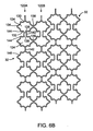
ステント・セグメント32の第1の好ましい幾何形状を図5A〜5Bで示す。図5Aは、非膨張構成のステント・セグメント32の一部を示し、図を見やすくするために平面形状で示してある。ステント・セグメント32は、ステント・セグメント32が円筒形を有するように軸Aの周囲に形成されたI形セル100の2つの平行の列98A、98Bを備える。各セル100は、軸方向に整列した上下の軸方向のスロット102と円周スロット104を有する。上下のスロット102は、好ましくは、全般的に軸Aに対して平行の長い長さLと軸Aに対して垂直の短い長さWを有する長円形、レーストラック形、長方形、または他の楕円形を有する。軸方向のスロット102は、上方の軸方向のストラット106と下方の軸方向のストラット107、湾曲した外端108、湾曲した内端110によって境界付けられている。各円周スロット104は、外側ストラット109と内側ストラット111によって境界付けられている。各I形セル100は、同じ列98Aまたは98Bの隣接するI形セル100に周方向の連結ストラット113によって連結される。列98AのI形セル100のすべてまたは一部は、隣接するセル100の内端110と一体に形成される、列98Bのセル100と内端110で合併または接合される。
A first preferred geometry for the
好ましい一実施形態では、間隔保持部材112は、選択された数の外側ストラット109および/または連結ストラット113から外側に軸方向に延びる。間隔保持部材112は、それ自体が内部にサブセル114を形成することが好ましいが、別法として間隔保持部材112内にセルまたは開口を持たない固体でもよい。外側ストラット109に取り付けられたこれらの間隔保持部材112では、サブセル114がI形セル100と連通することが好ましい。間隔保持部材112は、隣接するステント・セグメント32の湾曲した外端108と係合して、隣接するステント・セグメント間の適切な間隔を維持するように構成される。一実施形態では、間隔保持部材112は、2つの間隔をおいて配置された突起部118を備えた外端116を有し、クレードル様の構造となり、隣接するステント・セグメントの湾曲した外端108を位置決めし安定させる。間隔保持部材112の軸方向の長さは、I形セル100の長い長さLの、好ましくは少なくとも約10%、より好ましくは少なくとも約25%であり、隣接するステント・セグメントのI形セル100が少なくともその距離だけ間隔をおいて配置されるようにする。間隔保持部材112は、ステント・セグメント32の膨張中に、軸方向の短縮が少ししかなく、またはまったくないため、ステント・セグメント間のこの最小間隔が非膨張構成と膨張構成の両方で維持される。
In a preferred embodiment, the spacing
図5Bは、膨張した構成の図5Aのステント・セグメント32を示す。図で分かるように、セル100が膨張して、上下のスロット102がダイアモンド形になっており、円周スロット104は基本的に変化しないままである。そのため、ステント・セグメントのいくらかの軸方向の短縮が生じて、隣接するステント・セグメント間の間隔が大きくなる。ステントの幾何形状は、軸方向の短縮の程度と、関連するセグメント間の間隔、血管壁の範囲の所望の大きさ、所望の金属密度、その他の要因とのバランスを取ることによって最適にすることができる。ステントは複数の連結されていないステント・セグメント32からなるため、2から10まで、またはそれより大きい任意の所望数のステント・セグメントを同時に展開させて任意の長さの病変部を治療することができる。さらに、こうしたセグメントは互いに連結されていないため、配置されたステントの構造は非常に柔軟性があり、屈曲や他の複雑な形状を有する長い病変部への展開が可能である。
FIG. 5B shows the
追加の特徴として、円周スロット104は、それを通って血管の側枝にアクセスしてカテーテル・インターベンションを行うことができる通路を提供する。ステント・セグメント32を、アクセスが望まれる側枝の口を覆う位置に展開させる場合は、バルーン拡張カテーテルを円周スロット104を通して位置付けて膨張させることができる。それによって、図5Bの破線で示したように、円周ストラット109、111を軸方向に外側に変形させて、円周スロット104を膨張させ、さらに上下のスロット102を膨張させる。それによって比較的大きい開口120が形成される。その開口を介して、カテーテルをステント・セグメント32を通って側枝内に挿入し、ステントを配置し、血管形成術を行い、または他のインターベンションを実行することができる。
As an additional feature, the
図6A〜6Bは、本発明によるステント・セグメント32の第2の実施形態を示す。図6Aでは、図を見やすくするために、ステント・セグメント32の一部が平面形状で示されている。図5Aの実施形態と同様に、ステント・セグメント32は、軸Aの周囲に円筒形に形成されたI形セル124の2つの平行の列122A、122Bを備える。セル124は上下の軸方向のスロット126と連結円周スロット128を備える。上下のスロット126は、上方の軸方向のストラット130、下方の軸方向のストラット132、湾曲した外端134、湾曲した内端136によって境界付けられている。円周スロット128は、外側ストラット138と内側ストラット140によって境界付けられている。各I形セル124は、同じ列122内の隣接するI形セル124に円周の連結ストラット142によって連結される。列122Aは列122Bに各セル124内の上下のスロット126のうちの少なくとも1つの湾曲した内端136の合併または接合によって連結される。
6A-6B show a second embodiment of a
図6A〜6Bの実施形態と図5A〜5Bの実施形態の違いの1つは、間隔保持部が隣接するステント・セグメント間で保持される方法である。図6Aの実施形態は、前の実施形態の間隔保持部材112の代わりに、上下の軸方向のストラット130、132内の膨らみ144を備え、膨らみ144は軸方向のスロット126から円周方向に外側に延びる。この膨らみ144によって、軸方向のスロット126にスロット126の内端と外端に矢じりまたは十字の形状が与えられる。各上方の軸方向のストラット130の膨らみ144は、同じセル100または隣接するセル100内の下方の軸方向のストラット132内の膨らみ144に向かって延び、それによって各軸方向のスロット126の間の空間に凹面隣接部146が作成される。凹面隣接部146は、隣接するステント・セグメントのセル124の湾曲した外端134を受けて係合し、それによってステント・セグメント間の空間を維持するように構成される。所望の大きさのセグメント間の空間が得られるように、膨らみ144の軸方向の位置を上下の軸方向のストラット130、132に沿って選択することができる。
One difference between the embodiment of FIGS. 6A-6B and the embodiment of FIGS. 5A-5B is the manner in which the spacing retainer is retained between adjacent stent segments. The embodiment of FIG. 6A includes
図6Bは、膨張した構成の図6Aの2つのステント・セグメント32を示す。図を見ると分かるように、軸方向のスロット124が、この場合は斜めの上下の軸方向のストラット130、132上の膨らみ144によって周方向に拡張され変更されたダイアモンド形に変形されている。円周スロット128は、膨張した構成でも全般的に同じサイズと形状である。膨らみ144は、互いから離れるようにある程度引っ張られているが、なお凹面隣接部146を形成して、隣接するステント・セグメント間の最小空間が維持されている。前の実施形態のように、各セグメントのいくらかの軸方向の短縮が膨張時に生じるが、ステントの幾何形状を最適化して、理想のセグメント間の空間を形成するようにすることができる。
FIG. 6B shows the two
図6A〜6Bの実施形態は、図5A〜5Bに関する上記の特徴を保持し、ステント・セグメント32によって塞がれた血管の側枝にアクセスできるようになっていることも留意されたい。こうした側枝へのアクセスが望まれる場合、拡張カテーテルを円周スロット128内に挿入し膨張させて、拡大した開口を形成し、その開口を通って側枝に入ることができる。ステント・セグメント32の他の好ましい幾何形状が、参照により本明細書にすべて組み込まれている、米国特許出願第10/738666号明細書(代理人整理番号021629−000510US)に記載されている。
It should also be noted that the embodiment of FIGS. 6A-6B retains the features described above with respect to FIGS. 5A-5B and allows access to the side branch of the vessel occluded by the
次に図7A〜7Eを参照し、本発明のステント送出カテーテルの使用を記載する。本発明を冠動脈の治療のコンテキストで記載するが、本発明は、頚動脈、大腿、腸骨、その他の動脈、さらには、静脈や他の流体を搬送する脈管を含む、ステントが配置される広範な血管や他の身体管腔の任意のものに有用である。案内カテーテル(図示せず)が、大腿など末梢動脈内に先に挿入され、標的の冠動脈口に前進される。次いで案内ワイヤGWが、案内カテーテルを通り、病変部Lを治療すべき冠動脈Aに挿入される。次いで案内ワイヤGWの近位端が、ノーズ・コーン28と患者の身体の外部にある案内ワイヤ管34を通って挿入され、ステント送出カテーテル20が案内ワイヤGW上で案内カテーテルを通って冠動脈A内に摺動するように進められる。ステント送出カテーテル20は、ノーズ・コーン28が病変部Lの遠位になるように、治療すべき病変部Lを通って位置付けられる。この位置付け中、シース25はノーズ・コーン28まで遠位に位置付けられ、膨張可能な部材24とその上のステント・セグメント32すべてを取り囲むようになっている。
7A-7E, the use of the stent delivery catheter of the present invention will now be described. Although the present invention will be described in the context of coronary artery treatment, the present invention is broad in that a stent is deployed, including the carotid artery, femur, iliac, other arteries, and even vessels that carry veins and other fluids. Useful for any vessel or other body lumen. A guide catheter (not shown) is first inserted into a peripheral artery such as the thigh and advanced into the target coronary ostium. A guide wire GW is then inserted through the guide catheter and into the coronary artery A where the lesion L is to be treated. The proximal end of guide wire GW is then inserted through
任意選択で、ステントを配置する前に病変部Lを予め拡張することができる。血管形成用カテーテルを案内ワイヤGW上に挿入し病変部Lを拡張することによって、ステント送出カテーテル20を導入する前に予め拡張することができる。別法として、シース25をステント・セグメント32と共に引き込めて、膨張可能な部材24の端部を病変部全体にわたる十分な長さだけ露出させることによって、ステント送出カテーテル20を使用して予め膨張することができる。これは、送出カテーテル20を病変部Lの近位に位置付け、または膨張可能な部材24を病変部Lにわたって延ばすことで行うことができる。蛍光透視法によって、ユーザは、膨張可能な部材24の遠位端にあるマーカ82に対するシース25上のマーカ56の位置を観察することによって、病変部Lに対してシースを引き込める程度を見ることができる。ステント・セグメント32が膨張可能な部材24に対して近位に移動させるには、プッシャー管86から力を解放し、弁部材58がステント・セグメントと係合し、ステント・セグメントをシース25と共に近位に引き寄せる。膨張可能な部材24の適切な長さが露出された状態で、膨張可能な部材24が病変部L内に位置付けられ、膨張流体が膨張管腔66を通って導入されて、膨張可能な部材24をシース25の遠位で膨張させ、それによって病変部Lを拡張させる。次いで、膨張可能な部材24が収縮されてシース25内に引きこめられるが、プッシャー管86への力が維持されて、ステント・セグメント32が膨張可能な部材24の遠位端まで位置付けられシース25によって包囲される。病変部を予め拡張するための装置と方法の代替実施形態を以下に詳細に記載する。
Optionally, the lesion L can be pre-expanded before placing the stent. By inserting the angioplasty catheter onto the guide wire GW and expanding the lesion L, the
予備拡張に引き続き、図7Aで示したように、ノーズ・コーン28が病変部Lに対して遠位になるように、ステント送出カテーテル20が冠動脈A内に再位置付けされる。次いで、図7Bで示したように、シース25を引き込めて、病変部Lを覆うために適切な数のステント・セグメント32を露出させる。やはり、蛍光透視法を使用して、膨張可能な部材24内のマーカ82に対するシース25上のマーカ56を観察することによって、シース25の位置をみることができる。シース25が近位に引き寄せられたときに、プッシャー管86に対する力が維持され、ステント・セグメント32が膨張可能な部材24の遠位端部まで位置付けられたままになる。シース25は案内ワイヤ管34に対して近位に移動し、案内ワイヤ管34は案内ワイヤ管出口ポート35を通って摺動することも留意されたい。有利には、シース25の位置に関係なく、案内ワイヤ管34が案内ワイヤGWのための平滑で連続した通路を形成して、ステント送出カテーテルが案内ワイヤGW上を容易に摺動するようにされることである。任意選択で、膨張可能な部材24の遠位部分は、事前または後の拡張にさらに適するように、膨張可能な部材24の残りの部分とは異なる材料または異なるポリマー製剤で作成することができる異なるサイズのものでもよい。例えば、膨張可能な部材24の遠位部分のコンプライアンスを膨張可能な部材の残りの部分よりも低減し、かつ/または、ステント材料を配置するための比較的高圧の膨張に適したより剛性または耐性のあるポリマーで作成することができる。
Following pre-dilation, the
所望数のステント・セグメント32をシース25の遠位に露出した状態で、展開すべきステント・セグメント間の間隔をあけ、残りをシース25内で包囲することが望ましいことが多い。それによって、膨張可能な部材24が膨張したときに、シース25内で最遠位のステント・セグメント32が外れ、または部分的に膨張する危険性が低減される。図7Cで示したように、プッシャー管86に対する力を解放し、シース25を短距離だけ近位に引き込めることによってこうした間隔があけられる。弁部材58とステント・セグメント32の係合によって、シース25内のステント・セグメント32が、シース25に対して遠位にあるステント・セグメント32から離れるように移動させられる。この間隔の長さは好ましくは、ステント・セグメントの長さの約1/2〜1に等しい。
With the desired number of
次いで、図7Dで示したように、膨張流体を膨張管腔66を通して送ることによって、膨張可能な部材24が膨張させられる。膨張可能な部材24の露出された遠位部分が膨張して、膨張可能な部材24上のステント・セグメント32が膨張されて病変部Lと係合する。予め拡張されない場合は、膨張可能な部材24を適切に膨張させることによって、ステント・セグメント32の展開中に病変部Lを拡張することができる。シース25は、シース25内にある膨張可能な部材24の近位部分とステント・セグメント32の膨張を抑制する。
The
次いで、図7Eで示したように、膨張可能な部材24が収縮され、ステント・セグメント32は可塑的に変形し病変部L内で膨張した構成のままにされる。図6A〜6Bで示したステント・セグメント32の代替実施形態が図8で同様に膨張した状態で示されている。ステント・セグメント32が配置された状態で、膨張可能な部材24をシース25内に引き込め、やはりプッシャー管86に対する力を維持してステント・セグメント32を膨張可能な部材24の遠位端に位置付けることができる。膨張可能な部材24は、最遠位のステント・セグメントが停止部78(図2A〜2B)と係合するまでステント・セグメント32に対して近位に移動され、それによってステント・セグメント32が配置位置に配置される。このとき、ステント送出カテーテル20は、同じまたは異なる動脈の異なる病変部に再位置付けされる用意ができており、追加のステント・セグメントを配置することができる。こうした再位置付け中に、案内ワイヤ管34は、案内ワイヤGW上で円滑に追跡しやすくする。有利には、ステント送出カテーテル20を患者の身体から除去することなく、様々な長さの複数の病変部をこうして治療することができる。ステント送出カテーテル20を案内ワイヤGW上に導入すべき他のカテーテルと交換する必要がある場合は、案内ワイヤ管34によって迅速かつ簡単に交換しやすくなる。
Then, as shown in FIG. 7E, the
プッシャー管、シース、またはステント・セグメントの動きを本発明の送出カテーテルの他の構成要素に関連して記載する場合、こうした動きは相対的なものであり、シース、プッシャー管、またはステント・セグメントを移動させる一方で、他の1つまたは複数の構成要素は静止したままにし、シース、プッシャー管、またはステント・セグメントは静止したままで、他の1つまたは複数の構成要素を移動させ、あるいは、複数の構成要素を互いに同時に移動させることが包含される。 When movement of the pusher tube, sheath, or stent segment is described in relation to other components of the delivery catheter of the present invention, such movement is relative and the sheath, pusher tube, or stent segment is Moving one or more other components stationary while leaving the sheath, pusher tube, or stent segment stationary, moving one or more other components, or It involves moving a plurality of components simultaneously with respect to one another.
次に図9を参照すると、ステント送出カテーテル装置150の一実施形態は、その上に複数のステント・セグメント154を有するステントを位置付けることができるステント膨張部材152、ステント・セグメント154、ステント膨張部材152上に配置される内側シース156、ステント・セグメント154をステント膨張部材152に沿って摺動可能に前進させるプッシャー部材158、ノーズ・コーン164、外側シース162に結合された拡張部材160を適切に備える。内側シースは、ステント分離部材157を備えて、隣接するステント・セグメント154を分離させることができる。外側シース162を内側シース156上に配置して、拡張部材160を膨張させるための膨張管腔163を形成することができる。別法として、膨張管腔を内側シース156の壁内に配置することができ、または膨張管腔は内側シース156の外壁に固定または成形された管または管腔を備えることができる。上記の他の実施形態と同様に、カテーテル装置150を案内ワイヤ166上で送出することができる。
Referring now to FIG. 9, one embodiment of a stent
ステント送出カテーテル装置150は、上記の実施形態の多くのものと同様に使用することができ、1つまたは複数のステント・セグメント154を病変部に配置する前に、拡張部材160を使用して病変部を予め拡張する追加の特徴を有する。また、予め拡張しステント・セグメントを配置した後に、拡張部材160を収縮した形で、1つまたは複数の膨張したステント・セグメント154内に位置付け膨張させて、ステント・セグメント154をさらに膨張させ、ステント・セグメント154の完全な膨張を確保して、病変部などをさらに拡張することができる。外側シース162と内側シース156は、通常は共に引込み可能であり、1つまたは複数のステント・セグメント154および/またはステント膨張部材152の一部を露出させるようになっている。ステント分離部材157を使用して、隣接するステント・セグメント154を分離し、摺動可能なステント・セグメント154をステント膨張部材152上で引き込め、かつ/またはステント膨張部材152の前進中にステント・セグメント154を定位置に保持することができる。図9で示した実施形態では、別法として、ステント・セグメント154は自己膨張型でもよく、その場合、内側シース156は、内側シース156が引きこめられて1つまたは複数のステント・セグメントが治療部位で病変部内に自己膨張することができるようになるまで、ステント・セグメント154が膨張するのを抑制する。
The stent
次に図10を参照すると、ステント送出カテーテル装置170の他の実施形態は、ステント膨張部材172、ステント膨張部材172上に位置付け可能なステント・セグメント174を有するステント、膨張可能な部材172とステント・セグメント174上に配置され、ステント分離部材177を有するシース176、プッシャー部材178、ノーズ・コーン184、摺動可能な内部軸192、摺動可能な内部軸192に沿って配置された拡張部材190を備えている。やはり、カテーテル装置170を案内ワイヤ186に沿って前進させることができる。代替実施形態では、平坦な可撓性軸を、摺動可能ではなく、ノーズ・コーン184の遠位端に結合された拡張部材190と共にノーズ・コーン184に固定し、それから遠位に延ばすことができる。あるいは、拡張部材をノーズ・コーン自体などに結合することもできる。
Referring now to FIG. 10, another embodiment of the stent
摺動可能な内部軸192を軸方向に遠位と近位方向(両方向矢印)に移動させて、拡張部材190のすべてまたは一部を露出させ、すべてまたは一部をノーズ・コーン184かつ/または第1の膨張可能な部材172内に引き込めることができる。代替実施形態では、拡張部材190は図10で示したものよりもかなり長くてもよく(例えば約30〜100mm)、通常は拡張部材190の一部だけがノーズ・コーン184の遠位端から外に前進させられる。それによって、ユーザは、第2の膨張可能な部材190の膨張される部分の長さを調整して、拡張される病変部の長さに合うようにすることができる。ノーズ・コーン184は、第2の膨張可能な部材190の露出されない部分が、露出された遠位部分が膨張する間に膨張しないように抑制する。いずれにしても、拡張部材190を使用して、ステント・セグメント174を配置する前に病変部を予め拡張することができ、配置したステント・セグメント174をさらに膨張させ、ステント・セグメント174などの配置後に病変部をさらに膨張させることができる。
The slidable
図11A、11Bは、本発明の一実施形態による、血管V内の病変部Lを拡張し、ステント・セグメントを配置する方法を示す。この実施形態では、ステント送出カテーテル装置200は血管V内の病変部Lを治療する位置に、例えば装置200を案内ワイヤ216上で通過させることによって、または他の適した位置付け方法によって位置付けられる。次いでシース206を引き込め、かつ/または膨張可能な部材202を前進させて、膨張可能な部材202の一部をシース206の遠位に露出させることができる。シース206が引き込められると、ステント分離/保持部材207がステント・セグメント204を膨張可能な部材202に対して近位に摺動させて、膨張可能な部材202を病変部Lと同一の範囲に及ぶ所望の長さだけ露出させることができる。次いで、その上にステント・セグメント202を有していない膨張可能な部材202の露出された部分を膨張させて(一方向の矢印)病変部を予め拡張することができる。次いで、膨張可能な部材202をしぼませ/収縮し、ステント・セグメント204内の位置に引き戻すことができる。別法として、または追加で、シース206とプッシャー208を使用して、ステント・セグメント204をこのときは膨張していない膨張可能な部材202上で摺動可能に前進させることができる。
11A and 11B illustrate a method of dilating a lesion L in a blood vessel V and placing a stent segment according to one embodiment of the present invention. In this embodiment, the stent
図11Bで示したように、次にシース206を引き込めて、ステント・セグメント204と膨張可能な部材202の両方を露出させることができる。ステント・セグメント204の数と膨張可能な部材202の長さは、病変部Lの長さに合うように選択される。一部の実施形態では、ステント・セグメント204は自己膨張して病変部Lと接触し、他の実施形態では、ステント・セグメント204は膨張可能な部材202によって膨張される。ステント・セグメント204が膨張した後、膨張可能な部材202を任意選択で再膨張させて、セグメント204をさらに膨張させ、セグメント204が完全に膨張するようにして、病変部Lなどをさらに膨張させることができる。一部の実施形態では、装置200を再位置付けし、追加の1つまたは複数の病変部を予め拡張し、ステント・セグメントなどを配置することによって追加で血管Vに沿ったさらなる病変部を治療することができる。
As shown in FIG. 11B, the
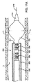
図12A〜12Eは、病変部Lを拡張し、病変部L内にステントを配置する方法の他の実施形態を示す。ステント送出カテーテル装置220は、案内ワイヤ236上で血管V内の病変部Lを治療する位置まで前進させられる。一実施形態では、カテーテル装置220は、外側の膨張可能な部材230に結合された外側シース232を備えており、そのどちらも内部カテーテル本体221上に摺動可能に配置される。図12Bで示したように、次いで外側の膨張可能な部材230を膨張させて、血管Vの病変部を含む部分に接触させて膨張させる。次いで、図12Cで示したように、外側の膨張可能な部材230を収縮させて外側シース232と共に引き込める。外側シース232と外側の膨張可能な部材230を引き込めることによって、1つまたは複数のステント・セグメント224を有するステントと内側の膨張可能な部材222を露出させることができる。一実施形態では、図12Dで示したように、ステント・セグメント224は自己膨張して病変部と接触する。図12Eで示したように、追加の任意選択のステップは、内側の膨張可能な部材222を膨張させて病変部Lをさらに拡張し、ステント・セグメント224をさらに膨張させ、ステント・セグメント224などの膨張を確実にすることを含む。
12A-12E illustrate another embodiment of a method for dilating a lesion L and placing a stent within the lesion L. FIGS. The stent
上記の方法へのいくつかの追加、変形、および変更を様々な実施形態に加えることができる。例えば、代替実施形態では、ステント・セグメント224を膨張させた後に外側の膨張可能な部材230を遠位に移動させ、セグメントをさらに膨張させるために再膨張させることができる。こうした実施形態では、外側の膨張可能な部材230など膨張可能な部材を1つだけ有すればよい。図11Aおよび11Bに関連して記載した他の実施形態では、内側の膨張可能な部材が1つしか使用されていない。やはり様々な実施形態で、拡張およびステント配置のステップの任意の適した組合せおよび順序を使用することができる。さらに、ステントの配置と組み合わせた拡張のための上記の装置および方法の様々な実施形態を、その両方が参照によりすべて本明細書に組み込まれている、2002年11月27日に出願の米国特許出願第10/306,622号明細書(代理人整理番号021629−000110US)と第10/306,620号明細書(代理人整理番号021629−000210US)に記載されたものを含む、様々なステントやステント送出システムの任意のものと共に使用することができる。
Several additions, variations, and modifications to the above method can be made to various embodiments. For example, in an alternative embodiment, after the
したがって、上記は本発明の好ましい実施形態の完全な記述であるが、本発明の範囲から逸脱することなく、様々な代替案、追加、変更、改善が可能である。例えば、本発明の上記の説明は、ステントを血管腔内に配置して開通性を維持するためのステント送出カテーテルを対象としたものであるが、様々な他のタイプのワイヤ案内式カテーテルも本発明の概念を実現するものである。例えば、血管形成術または他の目的のバルーン・カテーテル、特にバルーンを取り囲む摺動可能な外部シースを有するものを本発明により構築することができる。塞栓性コイル、ステント移植片、動脈瘤修復装置、環状形成リング、心臓弁、吻合装置、ステープルまたはクリップなど補綴装置を配置するための他のタイプのカテーテル、並びに超音波および血管形成カテーテル、電気生理学的マッピングと切除カテーテル、その他の装置にも本発明の概念を使用することができる。したがって、上記の説明は、主に例を示す目的で提供されたものであって、添付の特許請求の範囲を限定しないものであると解釈されるものとする。 Thus, while the above is a complete description of the preferred embodiments of the invention, various alternatives, additions, modifications and improvements are possible without departing from the scope of the invention. For example, the above description of the present invention is directed to a stent delivery catheter for placing a stent within a blood vessel lumen to maintain patency, although various other types of wire guided catheters are also described herein. The concept of the invention is realized. For example, a balloon catheter for angioplasty or other purposes, particularly one having a slidable outer sheath surrounding the balloon, can be constructed according to the present invention. Embolic coils, stent grafts, aneurysm repair devices, annuloplasty rings, heart valves, anastomosis devices, other types of catheters for placing prosthetic devices such as staples or clips, and ultrasound and angioplasty catheters, electrophysiology The concepts of the present invention can also be used for mechanical mapping and ablation catheters and other devices. Accordingly, the foregoing description has been provided primarily for purposes of illustration and should not be construed as limiting the scope of the appended claims.
Claims (79)
近位端と遠位端を有するカテーテル軸と、
前記カテーテル軸上に位置付け可能な少なくとも1つのステントと、
前記ステントの少なくとも一部を前記治療部位で展開させるステント展開機構であって、前記ステントの展開される部分の長さを選択することができるステント展開機構と、
前記少なくとも1つのステントの展開と関係なく、前記治療部位で病変部の少なくとも一部を拡張させる拡張部材とを備える装置。 A stent delivery device for delivering at least one stent to a treatment site,
A catheter shaft having a proximal end and a distal end;
At least one stent positionable on the catheter shaft;
A stent deployment mechanism for deploying at least a portion of the stent at the treatment site, the stent deployment mechanism being capable of selecting the length of the deployed portion of the stent;
An expansion member that expands at least a portion of a lesion at the treatment site regardless of deployment of the at least one stent.
前記カテーテル軸に前記遠位端付近で結合されたステント膨張部材と、
前記ステント膨張部材とその上のステントの少なくとも一部を覆って配置された少なくとも1つの軸方向に可動のシースとを備える請求項1に記載の装置。 The stent deployment mechanism comprises:
A stent expansion member coupled to the catheter shaft near the distal end;
The apparatus of claim 1, comprising the stent expansion member and at least one axially movable sheath disposed over at least a portion of the stent thereon.
近位端と遠位端を有するカテーテル軸と、
前記カテーテル軸に前記遠位端付近で結合された膨張可能な部材と、
前記膨張可能な部材上に摺動可能に位置付け可能な少なくとも1つのステントと、
前記膨張可能な部材とその上のステントの少なくとも一部上に配置された少なくとも1つの軸方向に可動のシースとを備え、前記シースが前記ステントを露出させずに前記膨張可能な部材の少なくとも一部を露出させるようにカテーテル本体に対して軸方向に可動であり、また、前記シースが前記ステントの少なくとも一部を露出させて前記ステントを膨張させようにも可動である装置。 A stent delivery device for delivering at least one stent to a treatment site,
A catheter shaft having a proximal end and a distal end;
An inflatable member coupled to the catheter shaft near the distal end;
At least one stent slidably positioned on the expandable member;
And an at least one axially movable sheath disposed on at least a portion of the stent thereon, wherein the sheath does not expose the stent and at least one of the expandable members. An apparatus that is axially movable relative to the catheter body so as to expose a portion, and wherein the sheath is also movable to expose at least a portion of the stent and expand the stent.
近位端と遠位端を有するカテーテル軸と、
前記カテーテル軸上に設けられ、前記カテーテル軸から展開可能な第1のステントと、
前記カテーテル軸上に設けられ、前記第1のステントとは関係なく前記カテーテル軸から展開可能な第2のステントと、
前記第1と第2のステントの配置とは関係なく前記標的部位を拡張させる拡張部材とを備える装置。 A stent delivery device for treating a target site in a blood vessel,
A catheter shaft having a proximal end and a distal end;
A first stent provided on the catheter shaft and deployable from the catheter shaft;
A second stent provided on the catheter shaft and deployable from the catheter shaft independently of the first stent;
An expansion member that expands the target site regardless of the placement of the first and second stents.
近位端と遠位端を有するカテーテル軸と、
前記カテーテル軸に前記遠位端付近で結合されたステント膨張部材と、
前記ステント膨張部材上に位置付け可能な少なくとも1つのステントと、
前記ステント膨張部材とその上のステントの少なくとも一部を覆って配置された少なくとも1つの軸方向に可動のシースと、
前記治療部位で1つまたは複数の病変部を拡張するための前記シースに結合された拡張部材とを備える装置。 A stent delivery device for delivering at least one stent to a treatment site,
A catheter shaft having a proximal end and a distal end;
A stent expansion member coupled to the catheter shaft near the distal end;
At least one stent positionable on the stent expansion member;
At least one axially movable sheath disposed over the stent expansion member and at least a portion of the stent thereon;
An expansion member coupled to the sheath for dilating one or more lesions at the treatment site.
近位端と遠位端を有するカテーテル軸と、
前記カテーテル軸上に位置付け可能な少なくとも1つのステントと、
前記カテーテル軸とステント上に配置された少なくとも1つの軸方向に可動のシースと、
前記カテーテル軸内に摺動可能に配置された内部軸と、
前記治療部位で1つまたは複数の病変部を拡張するための前記内部軸の遠位端に結合された拡張部材とを備える装置。 A stent delivery device for delivering at least one stent to a treatment site,
A catheter shaft having a proximal end and a distal end;
At least one stent positionable on the catheter shaft;
At least one axially movable sheath disposed on the catheter shaft and the stent;
An internal shaft slidably disposed within the catheter shaft;
An expansion member coupled to a distal end of the internal shaft for dilating one or more lesions at the treatment site.
少なくとも1つのステントを有するステント送出カテーテル装置の遠位部分を前記治療部位に位置付けるステップと、
前記治療部位で病変部の少なくとも一部を拡張させるために、前記カテーテル装置上で膨張可能な部材の少なくとも一部を膨張させるステップと、
選択された長さを有する前記ステントの展開可能な部分を選択するステップと、
前記ステントの配置されない部分を前記送出カテーテル内に残留させて、前記ステントの前記展開可能な部分を前記治療部位で膨張させるステップとを含む方法。 A method of delivering at least one stent to a treatment site, comprising:
Positioning a distal portion of a stent delivery catheter device having at least one stent at the treatment site;
Inflating at least a portion of an expandable member on the catheter device to expand at least a portion of a lesion at the treatment site;
Selecting a deployable portion of the stent having a selected length;
Leaving the undeployed portion of the stent within the delivery catheter and inflating the deployable portion of the stent at the treatment site.
前記膨張可能な部材が膨張していない形態に戻ることができるようにするステップと、および
前記膨張していない膨張可能な部材を前記少なくとも1つのステント・セグメント内の位置に引き込めることを含む請求項60に記載の方法。 Positioning the at least one stent segment on the expandable member;
Allowing the expandable member to return to an unexpanded configuration, and retracting the unexpanded expandable member to a location within the at least one stent segment. Item 60. The method according to Item 60.
ステント送出カテーテルが少なくとも1つのステントを有し、前記ステント送出カテーテル装置の遠位部分を前記治療部位に位置付けるステップと、
前記治療部位で病変部の少なくとも一部を拡張させるために、前記カテーテル装置上で膨張可能な部材の少なくとも一部を膨張させるステップと、
前記カテーテル装置上でシースを引き込めて、前記少なくとも1つのステントの少なくとも一部を前記シース内から露出させ、その部分を前記治療部位で自己膨張させるステップを含む方法。 A method of delivering at least one stent segment to a treatment site, comprising:
A stent delivery catheter having at least one stent and positioning a distal portion of the stent delivery catheter device at the treatment site;
Inflating at least a portion of an expandable member on the catheter device to expand at least a portion of a lesion at the treatment site;
Retracting a sheath over the catheter device to expose at least a portion of the at least one stent from within the sheath and self-expanding that portion at the treatment site.
前記膨張可能な部材を前記少なくとも1つの自己膨張したステント・セグメント内に位置付けるステップと、
前記膨張可能な部材の少なくとも一部を膨張させて前記ステント・セグメントをさらに膨張させるステップとをさらに含む請求項64に記載の方法。 After retracting the sheath,
Positioning the expandable member within the at least one self-expanding stent segment;
65. The method of claim 64, further comprising expanding at least a portion of the expandable member to further expand the stent segment.
ステント送出カテーテルが少なくとも1つのステントを有し、前記ステント送出カテーテル装置の遠位部分を前記治療部位に位置付けるステップと、
前記治療部位で病変部の少なくとも一部を拡張させるために、前記カテーテル装置の拡張部材の少なくとも一部を膨張させるステップと、
前記少なくとも1つのステントの少なくとも一部を前記治療部位に配置させるために、前記カテーテル装置のステント膨張部材の少なくとも一部を膨張させるステップを含む方法。 A method of delivering at least one stent to a treatment site, comprising:
A stent delivery catheter having at least one stent and positioning a distal portion of the stent delivery catheter device at the treatment site;
Inflating at least a portion of the expansion member of the catheter device to expand at least a portion of a lesion at the treatment site;
Inflating at least a portion of a stent expansion member of the catheter device to place at least a portion of the at least one stent at the treatment site.
Applications Claiming Priority (2)
| Application Number | Priority Date | Filing Date | Title |
|---|---|---|---|
| US10/794,405 US7351255B2 (en) | 2001-12-03 | 2004-03-03 | Stent delivery apparatus and method |
| PCT/US2005/007147 WO2005084382A2 (en) | 2004-03-03 | 2005-03-02 | Stent delivery apparatus and methods |
Publications (2)
| Publication Number | Publication Date |
|---|---|
| JP2007526096A true JP2007526096A (en) | 2007-09-13 |
| JP2007526096A5 JP2007526096A5 (en) | 2008-04-03 |
Family
ID=34919756
Family Applications (1)
| Application Number | Title | Priority Date | Filing Date |
|---|---|---|---|
| JP2007502027A Pending JP2007526096A (en) | 2004-03-03 | 2005-03-02 | Stent delivery apparatus and method |
Country Status (6)
| Country | Link |
|---|---|
| US (2) | US7351255B2 (en) |
| EP (1) | EP1771126B1 (en) |
| JP (1) | JP2007526096A (en) |
| AU (1) | AU2005218631A1 (en) |
| CA (1) | CA2558381A1 (en) |
| WO (1) | WO2005084382A2 (en) |
Cited By (3)
| Publication number | Priority date | Publication date | Assignee | Title |
|---|---|---|---|---|
| JP2010268950A (en) * | 2009-05-21 | 2010-12-02 | Kawasumi Lab Inc | Tubular treatment implement-indwelling apparatus |
| WO2012132753A1 (en) * | 2011-03-25 | 2012-10-04 | テルモ株式会社 | Stent and stent delivery system |
| JP2013240652A (en) * | 2006-01-30 | 2013-12-05 | Jw Medical Systems Ltd | Apparatus and method for deployment of custom-length prosthesis |
Families Citing this family (114)
| Publication number | Priority date | Publication date | Assignee | Title |
|---|---|---|---|---|
| EP1258230A3 (en) | 2001-03-29 | 2003-12-10 | CardioSafe Ltd | Balloon catheter device |
| GB0121980D0 (en) | 2001-09-11 | 2001-10-31 | Cathnet Science Holding As | Expandable stent |
| US8080048B2 (en) * | 2001-12-03 | 2011-12-20 | Xtent, Inc. | Stent delivery for bifurcated vessels |
| US7182779B2 (en) | 2001-12-03 | 2007-02-27 | Xtent, Inc. | Apparatus and methods for positioning prostheses for deployment from a catheter |
| US20030135266A1 (en) * | 2001-12-03 | 2003-07-17 | Xtent, Inc. | Apparatus and methods for delivery of multiple distributed stents |
| US7137993B2 (en) | 2001-12-03 | 2006-11-21 | Xtent, Inc. | Apparatus and methods for delivery of multiple distributed stents |
| US7309350B2 (en) | 2001-12-03 | 2007-12-18 | Xtent, Inc. | Apparatus and methods for deployment of vascular prostheses |
| US7892273B2 (en) | 2001-12-03 | 2011-02-22 | Xtent, Inc. | Custom length stent apparatus |
| US7351255B2 (en) | 2001-12-03 | 2008-04-01 | Xtent, Inc. | Stent delivery apparatus and method |
| US20040186551A1 (en) | 2003-01-17 | 2004-09-23 | Xtent, Inc. | Multiple independent nested stent structures and methods for their preparation and deployment |
| US7147656B2 (en) | 2001-12-03 | 2006-12-12 | Xtent, Inc. | Apparatus and methods for delivery of braided prostheses |
| US7294146B2 (en) | 2001-12-03 | 2007-11-13 | Xtent, Inc. | Apparatus and methods for delivery of variable length stents |
| DE10233085B4 (en) * | 2002-07-19 | 2014-02-20 | Dendron Gmbh | Stent with guide wire |
| US8425549B2 (en) | 2002-07-23 | 2013-04-23 | Reverse Medical Corporation | Systems and methods for removing obstructive matter from body lumens and treating vascular defects |
| US7241308B2 (en) | 2003-06-09 | 2007-07-10 | Xtent, Inc. | Stent deployment systems and methods |
| US7192440B2 (en) * | 2003-10-15 | 2007-03-20 | Xtent, Inc. | Implantable stent delivery devices and methods |
| US7403966B2 (en) * | 2003-12-08 | 2008-07-22 | Freescale Semiconductor, Inc. | Hardware for performing an arithmetic function |
| US7326236B2 (en) | 2003-12-23 | 2008-02-05 | Xtent, Inc. | Devices and methods for controlling and indicating the length of an interventional element |
| US7323006B2 (en) | 2004-03-30 | 2008-01-29 | Xtent, Inc. | Rapid exchange interventional devices and methods |
| US8317859B2 (en) | 2004-06-28 | 2012-11-27 | J.W. Medical Systems Ltd. | Devices and methods for controlling expandable prostheses during deployment |
| AU2005260787A1 (en) | 2004-06-28 | 2006-01-12 | Xtent, Inc. | Devices and methods for controlling expandable prostheses during deployment |
| US20050288766A1 (en) * | 2004-06-28 | 2005-12-29 | Xtent, Inc. | Devices and methods for controlling expandable prostheses during deployment |
| US20060135983A1 (en) * | 2004-12-16 | 2006-06-22 | Cook Incorporated | Catheter with tapered end balloon |
| US7402168B2 (en) * | 2005-04-11 | 2008-07-22 | Xtent, Inc. | Custom-length stent delivery system with independently operable expansion elements |
| US20060258981A1 (en) * | 2005-04-27 | 2006-11-16 | Tracee Eidenschink | Balloon catheter with perfusion lumen |
| US8641746B2 (en) * | 2005-05-31 | 2014-02-04 | J.W. Medical Systems Ltd. | In situ stent formation |
| US7320702B2 (en) * | 2005-06-08 | 2008-01-22 | Xtent, Inc. | Apparatus and methods for deployment of multiple custom-length prostheses (III) |
| CN101267781B (en) * | 2005-09-19 | 2011-06-08 | Minvasys公司 | Apparatus and methods for protected angioplasty and stenting at a carotid bifurcation |
| US20070073391A1 (en) * | 2005-09-28 | 2007-03-29 | Henry Bourang | System and method for delivering a mitral valve repair device |
| CN101437571B (en) | 2005-10-13 | 2013-01-02 | 斯恩蒂斯有限公司 | Drug-impregnated encasement |
| US20070129682A1 (en) * | 2005-12-02 | 2007-06-07 | Tracee Eidenschink | Guidewire with perfusion capability |
| EP1815821A1 (en) * | 2006-02-02 | 2007-08-08 | Dr. Karel Volenec - ELLA - CS | Stent delivery system |
| WO2007109621A2 (en) | 2006-03-20 | 2007-09-27 | Xtent, Inc. | Apparatus and methods for deployment of linked prosthetic segments |
| US20070288077A1 (en) * | 2006-06-07 | 2007-12-13 | Cherik Bulkes | Self-anchoring electrical lead with multiple electrodes |
| WO2007146075A2 (en) * | 2006-06-07 | 2007-12-21 | Cherik Bulkes | Analog signal transition detector |
| WO2007146076A2 (en) * | 2006-06-07 | 2007-12-21 | Cherik Bulkes | Biological tissue stimulator with flexible electrode carrier |
| US8057528B2 (en) * | 2006-06-20 | 2011-11-15 | Cook Medical Technologies Llc | Balloon-stent combination |
| US20080269865A1 (en) * | 2006-08-07 | 2008-10-30 | Xtent, Inc. | Custom Length Stent Apparatus |
| EP2374433B1 (en) * | 2006-09-06 | 2015-10-21 | Cook Medical Technologies LLC | Stents with connectors and stabilizing biodegradable elements |
| FR2911063B1 (en) | 2007-01-09 | 2009-03-20 | Stentys S A S Soc Par Actions | RUPTIBLE BRIDGE STRUCTURE FOR STENT, AND STENT INCLUDING SUCH BRIDGE STRUCTURES. |
| US20080199510A1 (en) | 2007-02-20 | 2008-08-21 | Xtent, Inc. | Thermo-mechanically controlled implants and methods of use |
| US8486132B2 (en) | 2007-03-22 | 2013-07-16 | J.W. Medical Systems Ltd. | Devices and methods for controlling expandable prostheses during deployment |
| US8052639B2 (en) * | 2007-04-10 | 2011-11-08 | Wilson David B | Clampless anastomotic device |
| US20080255653A1 (en) * | 2007-04-13 | 2008-10-16 | Medtronic Vascular, Inc. | Multiple Stent Delivery System and Method |
| US8366628B2 (en) * | 2007-06-07 | 2013-02-05 | Kenergy, Inc. | Signal sensing in an implanted apparatus with an internal reference |
| WO2009002819A2 (en) | 2007-06-22 | 2008-12-31 | Cr Bard Inc. | Locked segments pushable stent-graft |
| CA2691064C (en) * | 2007-06-22 | 2015-11-24 | David L. Bogert | Helical and segmented stent-graft |
| US8858490B2 (en) | 2007-07-18 | 2014-10-14 | Silk Road Medical, Inc. | Systems and methods for treating a carotid artery |
| WO2009012473A2 (en) | 2007-07-18 | 2009-01-22 | Silk Road Medical, Inc. | Methods and systems for establishing retrograde carotid arterial blood flow |
| DE102007040868A1 (en) * | 2007-08-29 | 2009-04-16 | Innora Gmbh | Balloon catheter with protection against unfolding |
| US8585713B2 (en) | 2007-10-17 | 2013-11-19 | Covidien Lp | Expandable tip assembly for thrombus management |
| US9198687B2 (en) | 2007-10-17 | 2015-12-01 | Covidien Lp | Acute stroke revascularization/recanalization systems processes and products thereby |
| US20100256600A1 (en) * | 2009-04-04 | 2010-10-07 | Ferrera David A | Neurovascular otw pta balloon catheter and delivery system |
| US11337714B2 (en) | 2007-10-17 | 2022-05-24 | Covidien Lp | Restoring blood flow and clot removal during acute ischemic stroke |
| US8066757B2 (en) | 2007-10-17 | 2011-11-29 | Mindframe, Inc. | Blood flow restoration and thrombus management methods |
| US8926680B2 (en) | 2007-11-12 | 2015-01-06 | Covidien Lp | Aneurysm neck bridging processes with revascularization systems methods and products thereby |
| US9220522B2 (en) | 2007-10-17 | 2015-12-29 | Covidien Lp | Embolus removal systems with baskets |
| US8088140B2 (en) | 2008-05-19 | 2012-01-03 | Mindframe, Inc. | Blood flow restorative and embolus removal methods |
| US10123803B2 (en) | 2007-10-17 | 2018-11-13 | Covidien Lp | Methods of managing neurovascular obstructions |
| US9603730B2 (en) | 2007-12-12 | 2017-03-28 | Intact Vascular, Inc. | Endoluminal device and method |
| US10166127B2 (en) | 2007-12-12 | 2019-01-01 | Intact Vascular, Inc. | Endoluminal device and method |
| US10022250B2 (en) | 2007-12-12 | 2018-07-17 | Intact Vascular, Inc. | Deployment device for placement of multiple intraluminal surgical staples |
| US9375327B2 (en) | 2007-12-12 | 2016-06-28 | Intact Vascular, Inc. | Endovascular implant |
| US20110230954A1 (en) * | 2009-06-11 | 2011-09-22 | Peter Schneider | Stent device having focal elevating elements for minimal surface area contact with lumen walls |
| US8128677B2 (en) | 2007-12-12 | 2012-03-06 | Intact Vascular LLC | Device and method for tacking plaque to a blood vessel wall |
| US7896911B2 (en) * | 2007-12-12 | 2011-03-01 | Innovasc Llc | Device and method for tacking plaque to blood vessel wall |
| US11589880B2 (en) | 2007-12-20 | 2023-02-28 | Angiodynamics, Inc. | System and methods for removing undesirable material within a circulatory system utilizing during a surgical procedure |
| US10517617B2 (en) | 2007-12-20 | 2019-12-31 | Angiodynamics, Inc. | Systems and methods for removing undesirable material within a circulatory system utilizing a balloon catheter |
| JP2011510796A (en) | 2008-02-05 | 2011-04-07 | シルク・ロード・メディカル・インコーポレイテッド | Intervention catheter system and method |
| US8940003B2 (en) | 2008-02-22 | 2015-01-27 | Covidien Lp | Methods and apparatus for flow restoration |
| US9101503B2 (en) | 2008-03-06 | 2015-08-11 | J.W. Medical Systems Ltd. | Apparatus having variable strut length and methods of use |
| EP2271390A4 (en) | 2008-04-11 | 2016-07-20 | Covidien Lp | Monorail neuro-microcatheter for delivery of medical devices to treat stroke, processes and products thereby |
| US20090264859A1 (en) * | 2008-04-21 | 2009-10-22 | Medtronic Vascular, Inc. | Catheter Having a Selectively Expandable Distal Tip |
| EP2293838B1 (en) * | 2008-07-01 | 2012-08-08 | Endologix, Inc. | Catheter system |
| US11298252B2 (en) | 2008-09-25 | 2022-04-12 | Advanced Bifurcation Systems Inc. | Stent alignment during treatment of a bifurcation |
| US8769796B2 (en) | 2008-09-25 | 2014-07-08 | Advanced Bifurcation Systems, Inc. | Selective stent crimping |
| US8821562B2 (en) | 2008-09-25 | 2014-09-02 | Advanced Bifurcation Systems, Inc. | Partially crimped stent |
| CN102215780B (en) | 2008-09-25 | 2015-10-14 | 高级分支系统股份有限公司 | Part crimped stent |
| WO2011119883A1 (en) | 2010-03-24 | 2011-09-29 | Advanced Bifurcation Systems, Inc. | Stent alignment during treatment of a bifurcation |
| AU2011232360B2 (en) | 2010-03-24 | 2015-10-08 | Advanced Bifurcation Systems Inc. | Methods and systems for treating a bifurcation with provisional side branch stenting |
| CN103037816B (en) | 2010-03-24 | 2018-12-28 | 高级分支系统股份有限公司 | System and method for handling furcation |
| US10039900B2 (en) * | 2010-09-07 | 2018-08-07 | Angiodynamics, Inc. | Fluid delivery and treatment device and method of use |
| US9039749B2 (en) | 2010-10-01 | 2015-05-26 | Covidien Lp | Methods and apparatuses for flow restoration and implanting members in the human body |
| US10449071B2 (en) * | 2010-12-22 | 2019-10-22 | Boston Scientific Scimed, Inc. | Stent deployment system with integrated digital camera and dilation balloon |
| WO2012109382A2 (en) | 2011-02-08 | 2012-08-16 | Advanced Bifurcation Systems, Inc. | Multi-stent and multi-balloon apparatus for treating bifurcations and methods of use |
| EP2672932B1 (en) | 2011-02-08 | 2018-09-19 | Advanced Bifurcation Systems, Inc. | System for treating a bifurcation with a fully crimped stent |
| WO2012118901A1 (en) | 2011-03-01 | 2012-09-07 | Endologix, Inc. | Catheter system and methods of using same |
| US9055964B2 (en) | 2011-03-15 | 2015-06-16 | Angio Dynamics, Inc. | Device and method for removing material from a hollow anatomical structure |
| US10285831B2 (en) | 2011-06-03 | 2019-05-14 | Intact Vascular, Inc. | Endovascular implant |
| US8734500B2 (en) | 2011-09-27 | 2014-05-27 | DePuy Synthes Products, LLC | Distal detachment mechanisms for vascular devices |
| US9554904B2 (en) | 2011-09-28 | 2017-01-31 | Medtronic CV Luxembourg S.a.r.l. | Distal tip assembly for a heart valve delivery catheter |
| TWI590843B (en) | 2011-12-28 | 2017-07-11 | 信迪思有限公司 | Films and methods of manufacture |
| CA2986656A1 (en) | 2012-01-25 | 2013-08-01 | Intact Vascular, Inc. | Endoluminal device and method |
| US8911490B2 (en) | 2012-03-27 | 2014-12-16 | Medtronic Vascular, Inc. | Integrated mesh high metal to vessel ratio stent and method |
| US9005270B2 (en) | 2012-03-27 | 2015-04-14 | Medtronic Vascular, Inc. | High metal to vessel ratio stent and method |
| KR101231197B1 (en) * | 2012-09-20 | 2013-02-07 | 썬텍 주식회사 | Polymeric stent |
| US10010436B2 (en) | 2012-09-20 | 2018-07-03 | Dotter Intellectual Pte, Ltd. | Polymeric stent and methods of manufacturing the same |
| US9907684B2 (en) | 2013-05-08 | 2018-03-06 | Aneuclose Llc | Method of radially-asymmetric stent expansion |
| CA2916249C (en) | 2013-06-21 | 2021-07-13 | DePuy Synthes Products, Inc. | Films and methods of manufacture |
| US9375336B1 (en) | 2015-01-29 | 2016-06-28 | Intact Vascular, Inc. | Delivery device and method of delivery |
| US9456914B2 (en) | 2015-01-29 | 2016-10-04 | Intact Vascular, Inc. | Delivery device and method of delivery |
| US9433520B2 (en) | 2015-01-29 | 2016-09-06 | Intact Vascular, Inc. | Delivery device and method of delivery |
| US9192500B1 (en) | 2015-01-29 | 2015-11-24 | Intact Vascular, Inc. | Delivery device and method of delivery |
| WO2017004265A1 (en) | 2015-06-30 | 2017-01-05 | Endologix, Inc. | Locking assembly for coupling guidewire to delivery system |
| US10993824B2 (en) | 2016-01-01 | 2021-05-04 | Intact Vascular, Inc. | Delivery device and method of delivery |
| US20200100776A1 (en) * | 2017-02-09 | 2020-04-02 | Intuitive Surgical Operations, Inc. | System and method of accessing encapsulated targets |
| US11660218B2 (en) | 2017-07-26 | 2023-05-30 | Intact Vascular, Inc. | Delivery device and method of delivery |
| US10441449B1 (en) | 2018-05-30 | 2019-10-15 | Vesper Medical, Inc. | Rotary handle stent delivery system and method |
| CN108852575B (en) * | 2018-07-11 | 2023-11-10 | 浙江巴泰医疗科技有限公司 | Multisection application operating system of closed self-expansion unit bracket |
| CN108852570B (en) * | 2018-07-11 | 2023-12-01 | 浙江巴泰医疗科技有限公司 | Closed self-expansion unit bracket |
| US10449073B1 (en) | 2018-09-18 | 2019-10-22 | Vesper Medical, Inc. | Rotary handle stent delivery system and method |
| US11648020B2 (en) | 2020-02-07 | 2023-05-16 | Angiodynamics, Inc. | Device and method for manual aspiration and removal of an undesirable material |
| CN115279308A (en) | 2020-03-11 | 2022-11-01 | 高级分支系统股份有限公司 | Stent retention |
| US11219541B2 (en) | 2020-05-21 | 2022-01-11 | Vesper Medical, Inc. | Wheel lock for thumbwheel actuated device |
Citations (3)
| Publication number | Priority date | Publication date | Assignee | Title |
|---|---|---|---|---|
| JPH08238322A (en) * | 1994-10-20 | 1996-09-17 | Cordis Europ Nv | Catheter for stent embedding |
| WO2003047651A2 (en) * | 2001-12-03 | 2003-06-12 | Xtent, Inc. | Apparatus and methods for delivery of multiple distributed stents |
| JP2003530200A (en) * | 2000-04-12 | 2003-10-14 | ボストン サイエンティフィック リミテッド | Stent delivery catheter with retractable balloon |
Family Cites Families (422)
| Publication number | Priority date | Publication date | Assignee | Title |
|---|---|---|---|---|
| US4069825A (en) | 1976-01-28 | 1978-01-24 | Taichiro Akiyama | Surgical thread and cutting apparatus for the same |
| US4564014A (en) | 1980-01-30 | 1986-01-14 | Thomas J. Fogarty | Variable length dilatation catheter apparatus and method |
| US4468224A (en) | 1982-01-28 | 1984-08-28 | Advanced Cardiovascular Systems, Inc. | System and method for catheter placement in blood vessels of a human patient |
| US4512338A (en) | 1983-01-25 | 1985-04-23 | Balko Alexander B | Process for restoring patency to body vessels |
| US5693083A (en) | 1983-12-09 | 1997-12-02 | Endovascular Technologies, Inc. | Thoracic graft and delivery catheter |
| US4891225A (en) | 1984-05-21 | 1990-01-02 | Massachusetts Institute Of Technology | Bioerodible polyanhydrides for controlled drug delivery |
| US4580568A (en) | 1984-10-01 | 1986-04-08 | Cook, Incorporated | Percutaneous endovascular stent and method for insertion thereof |
| DE3442736A1 (en) | 1984-11-23 | 1986-06-05 | Tassilo Dr.med. 7800 Freiburg Bonzel | DILATATION CATHETER |
| US4690684A (en) | 1985-07-12 | 1987-09-01 | C. R. Bard, Inc. | Meltable stent for anastomosis |
| US4770176A (en) | 1985-07-12 | 1988-09-13 | C. R. Bard, Inc. | Vessel anastomosis using meltable stent |
| US4733665C2 (en) | 1985-11-07 | 2002-01-29 | Expandable Grafts Partnership | Expandable intraluminal graft and method and apparatus for implanting an expandable intraluminal graft |
| US5102417A (en) | 1985-11-07 | 1992-04-07 | Expandable Grafts Partnership | Expandable intraluminal graft, and method and apparatus for implanting an expandable intraluminal graft |
| US4681110A (en) | 1985-12-02 | 1987-07-21 | Wiktor Dominik M | Catheter arrangement having a blood vessel liner, and method of using it |
| US5061273A (en) | 1989-06-01 | 1991-10-29 | Yock Paul G | Angioplasty apparatus facilitating rapid exchanges |
| US5040548A (en) | 1989-06-01 | 1991-08-20 | Yock Paul G | Angioplasty mehtod |
| US5350395A (en) | 1986-04-15 | 1994-09-27 | Yock Paul G | Angioplasty apparatus facilitating rapid exchanges |
| US4775337A (en) | 1986-12-02 | 1988-10-04 | Universal Manufacturing Corporation | Conductive wire with integral electrical terminal |
| US4748982A (en) | 1987-01-06 | 1988-06-07 | Advanced Cardiovascular Systems, Inc. | Reinforced balloon dilatation catheter with slitted exchange sleeve and method |
| US4988356A (en) | 1987-02-27 | 1991-01-29 | C. R. Bard, Inc. | Catheter and guidewire exchange system |
| EP0282143B1 (en) | 1987-02-27 | 1993-09-15 | C.R. Bard, Inc. | Catheter and guidewire exchange system |
| US4886062A (en) | 1987-10-19 | 1989-12-12 | Medtronic, Inc. | Intravascular radially expandable stent and method of implant |
| US5171222A (en) | 1988-03-10 | 1992-12-15 | Scimed Life Systems, Inc. | Interlocking peel-away dilation catheter |
| US4994298A (en) | 1988-06-07 | 1991-02-19 | Biogold Inc. | Method of making a biocompatible prosthesis |
| US6730105B2 (en) | 1988-07-29 | 2004-05-04 | Samuel Shiber | Clover leaf shaped tubular medical device |
| US5092877A (en) | 1988-09-01 | 1992-03-03 | Corvita Corporation | Radially expandable endoprosthesis |
| US5226913A (en) | 1988-09-01 | 1993-07-13 | Corvita Corporation | Method of making a radially expandable prosthesis |
| CA1322628C (en) | 1988-10-04 | 1993-10-05 | Richard A. Schatz | Expandable intraluminal graft |
| US4994066A (en) | 1988-10-07 | 1991-02-19 | Voss Gene A | Prostatic stent |
| US4994069A (en) | 1988-11-02 | 1991-02-19 | Target Therapeutics | Vaso-occlusion coil and method |
| US4950227A (en) | 1988-11-07 | 1990-08-21 | Boston Scientific Corporation | Stent delivery system |
| DE8916283U1 (en) | 1989-01-30 | 1997-05-15 | Bard Inc C R | Quickly replaceable coronary catheter |
| US5217495A (en) | 1989-05-10 | 1993-06-08 | United States Surgical Corporation | Synthetic semiabsorbable composite yarn |
| US5292331A (en) | 1989-08-24 | 1994-03-08 | Applied Vascular Engineering, Inc. | Endovascular support device |
| CA2026604A1 (en) | 1989-10-02 | 1991-04-03 | Rodney G. Wolff | Articulated stent |
| US5035706A (en) | 1989-10-17 | 1991-07-30 | Cook Incorporated | Percutaneous stent and method for retrieval thereof |
| US5061274A (en) | 1989-12-04 | 1991-10-29 | Kensey Nash Corporation | Plug device for sealing openings and method of use |
| US5158548A (en) | 1990-04-25 | 1992-10-27 | Advanced Cardiovascular Systems, Inc. | Method and system for stent delivery |
| US5064435A (en) | 1990-06-28 | 1991-11-12 | Schneider (Usa) Inc. | Self-expanding prosthesis having stable axial length |
| US5013318A (en) | 1990-07-31 | 1991-05-07 | Special Devices Incorporated | Medical instrument for measuring depth of fastener hold in bone |
| US5122154A (en) | 1990-08-15 | 1992-06-16 | Rhodes Valentine J | Endovascular bypass graft |
| AR246020A1 (en) | 1990-10-03 | 1994-03-30 | Hector Daniel Barone Juan Carl | A ball device for implanting an intraluminous aortic prosthesis, for repairing aneurysms. |
| DE9117152U1 (en) | 1990-10-09 | 1996-07-11 | Cook Inc | Stent |
| CA2060067A1 (en) | 1991-01-28 | 1992-07-29 | Lilip Lau | Stent delivery system |
| US5533968A (en) | 1991-05-15 | 1996-07-09 | Advanced Cardiovascular Systems, Inc. | Low profile catheter with expandable outer tubular member |
| US5135535A (en) | 1991-06-11 | 1992-08-04 | Advanced Cardiovascular Systems, Inc. | Catheter system with catheter and guidewire exchange |
| US5527354A (en) | 1991-06-28 | 1996-06-18 | Cook Incorporated | Stent formed of half-round wire |
| US5976107A (en) | 1991-07-05 | 1999-11-02 | Scimed Life Systems. Inc. | Catheter having extendable guide wire lumen |
| US5490837A (en) | 1991-07-05 | 1996-02-13 | Scimed Life Systems, Inc. | Single operator exchange catheter having a distal catheter shaft section |
| ATE112847T1 (en) | 1991-07-29 | 1994-10-15 | Brandes Bernd | EQUIPMENT AND PROCEDURE FOR DETECTING LEAKS IN TUBES FOR LIQUID MEDIA. |
| US5443498A (en) | 1991-10-01 | 1995-08-22 | Cook Incorporated | Vascular stent and method of making and implanting a vacsular stent |
| US5456713A (en) | 1991-10-25 | 1995-10-10 | Cook Incorporated | Expandable transluminal graft prosthesis for repairs of aneurysm and method for implanting |
| CA2380683C (en) | 1991-10-28 | 2006-08-08 | Advanced Cardiovascular Systems, Inc. | Expandable stents and method for making same |
| US5628775A (en) | 1991-11-08 | 1997-05-13 | Ep Technologies, Inc. | Flexible bond for sleeves enclosing a bendable electrode tip assembly |
| US5192297A (en) | 1991-12-31 | 1993-03-09 | Medtronic, Inc. | Apparatus and method for placement and implantation of a stent |
| DE69330119T2 (en) | 1992-01-09 | 2001-08-02 | Advanced Cardiovascular System | DEVICE FOR REPLACING A GUIDE WIRE |
| US5246421A (en) | 1992-02-12 | 1993-09-21 | Saab Mark A | Method of treating obstructed regions of bodily passages |
| US5273536A (en) | 1992-04-02 | 1993-12-28 | Vicky Savas | Tapered balloon catheter |
| US5201757A (en) | 1992-04-03 | 1993-04-13 | Schneider (Usa) Inc. | Medial region deployment of radially self-expanding stents |
| US5507771A (en) | 1992-06-15 | 1996-04-16 | Cook Incorporated | Stent assembly |
| US5562725A (en) | 1992-09-14 | 1996-10-08 | Meadox Medicals Inc. | Radially self-expanding implantable intraluminal device |
| US5312415A (en) | 1992-09-22 | 1994-05-17 | Target Therapeutics, Inc. | Assembly for placement of embolic coils using frictional placement |
| ES2089342T3 (en) | 1992-10-31 | 1996-10-01 | Schneider Europ Ag | DISPOSITION OF INTRODUCTION OF A SELF-EXPANDING ENDOPROTESIS. |
| US5336178A (en) | 1992-11-02 | 1994-08-09 | Localmed, Inc. | Intravascular catheter with infusion array |
| CA2149887A1 (en) | 1992-12-30 | 1994-07-21 | Steven J. Healy | Apparatus for deploying body implantable stents |
| US5607463A (en) | 1993-03-30 | 1997-03-04 | Medtronic, Inc. | Intravascular medical device |
| JPH08509642A (en) | 1993-04-28 | 1996-10-15 | フォーカル,インコーポレイテッド | Device and method for intraluminal photothermoforming |
| US5549553A (en) | 1993-04-29 | 1996-08-27 | Scimed Life Systems, Inc. | Dilation ballon for a single operator exchange intravascular catheter or similar device |
| US5480423A (en) | 1993-05-20 | 1996-01-02 | Boston Scientific Corporation | Prosthesis delivery |
| US5334187A (en) | 1993-05-21 | 1994-08-02 | Cathco, Inc. | Balloon catheter system with slit opening handle |
| US5391172A (en) | 1993-05-24 | 1995-02-21 | Advanced Cardiovascular Systems, Inc. | Stent delivery system with coaxial catheter handle |
| US5458615A (en) | 1993-07-06 | 1995-10-17 | Advanced Cardiovascular Systems, Inc. | Stent delivery system |
| US5735892A (en) * | 1993-08-18 | 1998-04-07 | W. L. Gore & Associates, Inc. | Intraluminal stent graft |
| US5545209A (en) | 1993-09-30 | 1996-08-13 | Texas Petrodet, Inc. | Controlled deployment of a medical device |
| US5445646A (en) | 1993-10-22 | 1995-08-29 | Scimed Lifesystems, Inc. | Single layer hydraulic sheath stent delivery apparatus and method |
| US5989280A (en) | 1993-10-22 | 1999-11-23 | Scimed Lifesystems, Inc | Stent delivery apparatus and method |
| US5607444A (en) | 1993-12-02 | 1997-03-04 | Advanced Cardiovascular Systems, Inc. | Ostial stent for bifurcations |
| US5549635A (en) | 1994-01-24 | 1996-08-27 | Solar, Rita & Gaterud, Ltd. | Non-deformable self-expanding parallel flow endovascular stent and deployment apparatus therefore |
| US6051020A (en) | 1994-02-09 | 2000-04-18 | Boston Scientific Technology, Inc. | Bifurcated endoluminal prosthesis |
| DE69514690T3 (en) | 1994-02-25 | 2006-09-14 | Fischell, Robert E. | stent |
| US5453090A (en) | 1994-03-01 | 1995-09-26 | Cordis Corporation | Method of stent delivery through an elongate softenable sheath |
| US5449373A (en) | 1994-03-17 | 1995-09-12 | Medinol Ltd. | Articulated stent |
| CA2261941C (en) | 1994-04-01 | 2005-06-21 | Prograft Medical, Inc. | Self-expandable stent and stent-graft and method of using them |
| US6165210A (en) | 1994-04-01 | 2000-12-26 | Gore Enterprise Holdings, Inc. | Self-expandable helical intravascular stent and stent-graft |
| US5478349A (en) | 1994-04-28 | 1995-12-26 | Boston Scientific Corporation | Placement of endoprostheses and stents |
| DE69527141T2 (en) | 1994-04-29 | 2002-11-07 | Scimed Life Systems Inc | STENT WITH COLLAGEN |
| JP3647456B2 (en) | 1994-04-29 | 2005-05-11 | ボストン・サイエンティフィック・コーポレーション | Medical artificial stent and method for producing the same |
| US5554181A (en) | 1994-05-04 | 1996-09-10 | Regents Of The University Of Minnesota | Stent |
| US5456694A (en) | 1994-05-13 | 1995-10-10 | Stentco, Inc. | Device for delivering and deploying intraluminal devices |
| US5514093A (en) | 1994-05-19 | 1996-05-07 | Scimed Life Systems, Inc. | Variable length balloon dilatation catheter |
| DE4418336A1 (en) | 1994-05-26 | 1995-11-30 | Angiomed Ag | Stent for widening and holding open receptacles |
| US5824041A (en) | 1994-06-08 | 1998-10-20 | Medtronic, Inc. | Apparatus and methods for placement and repositioning of intraluminal prostheses |
| US5683451A (en) | 1994-06-08 | 1997-11-04 | Cardiovascular Concepts, Inc. | Apparatus and methods for deployment release of intraluminal prostheses |
| US5636641A (en) | 1994-07-25 | 1997-06-10 | Advanced Cardiovascular Systems, Inc. | High strength member for intracorporeal use |
| US5575816A (en) | 1994-08-12 | 1996-11-19 | Meadox Medicals, Inc. | High strength and high density intraluminal wire stent |
| US5723003A (en) | 1994-09-13 | 1998-03-03 | Ultrasonic Sensing And Monitoring Systems | Expandable graft assembly and method of use |
| US5470315A (en) | 1994-09-20 | 1995-11-28 | Scimed Life Systems, Inc. | Over-the-wire type balloon catheter with proximal hypotube |
| US5531735A (en) | 1994-09-27 | 1996-07-02 | Hercules Incorporated | Medical devices containing triggerable disintegration agents |
| US5549563A (en) | 1994-10-11 | 1996-08-27 | Kronner; Richard F. | Reinforcing insert for uterine manipulator |
| US5836964A (en) | 1996-10-30 | 1998-11-17 | Medinol Ltd. | Stent fabrication method |
| CA2163823A1 (en) | 1994-11-28 | 1996-05-29 | Richard S. Stack | System and method for delivering multiple stents |
| US5735869A (en) | 1994-11-30 | 1998-04-07 | Schneider (Europe) A.G. | Balloon catheter and stent delivery device |
| US5628755A (en) | 1995-02-20 | 1997-05-13 | Schneider (Europe) A.G. | Balloon catheter and stent delivery system |
| CA2163708C (en) | 1994-12-07 | 2007-08-07 | Robert E. Fischell | Integrated dual-function catheter system for balloon angioplasty and stent delivery |
| US5549551A (en) | 1994-12-22 | 1996-08-27 | Advanced Cardiovascular Systems, Inc. | Adjustable length balloon catheter |
| US5662675A (en) | 1995-02-24 | 1997-09-02 | Intervascular, Inc. | Delivery catheter assembly |
| DE69637527D1 (en) | 1995-03-01 | 2008-06-26 | Boston Scient Scimed Inc | Longitudinally flexible and expandable stent |
| US7204848B1 (en) | 1995-03-01 | 2007-04-17 | Boston Scientific Scimed, Inc. | Longitudinally flexible expandable stent |
| US5709713A (en) | 1995-03-31 | 1998-01-20 | Cardiovascular Concepts, Inc. | Radially expansible vascular prosthesis having reversible and other locking structures |
| US5807398A (en) | 1995-04-28 | 1998-09-15 | Shaknovich; Alexander | Shuttle stent delivery catheter |
| FR2733682B1 (en) | 1995-05-04 | 1997-10-31 | Dibie Alain | ENDOPROSTHESIS FOR THE TREATMENT OF STENOSIS ON BIFURCATIONS OF BLOOD VESSELS AND LAYING EQUIPMENT THEREFOR |
| US5534007A (en) | 1995-05-18 | 1996-07-09 | Scimed Life Systems, Inc. | Stent deployment catheter with collapsible sheath |
| US5681347A (en) | 1995-05-23 | 1997-10-28 | Boston Scientific Corporation | Vena cava filter delivery system |
| JPH10503411A (en) | 1995-05-25 | 1998-03-31 | メドトロニック・インコーポレーテッド | Stent assembly and method of using the same |
| US5639274A (en) | 1995-06-02 | 1997-06-17 | Fischell; Robert E. | Integrated catheter system for balloon angioplasty and stent delivery |
| CA2223399C (en) | 1995-06-06 | 2003-08-05 | Corvita Corporation | Endovascular measuring apparatus, loading and deployment means |
| US6010530A (en) | 1995-06-07 | 2000-01-04 | Boston Scientific Technology, Inc. | Self-expanding endoluminal prosthesis |
| AU5776696A (en) | 1995-06-08 | 1997-01-09 | Bard Galway Limited | Bifurcated endovascular stent |
| JP3467916B2 (en) | 1995-07-10 | 2003-11-17 | 松下電器産業株式会社 | Transmission / reception method |
| US5877224A (en) | 1995-07-28 | 1999-03-02 | Rutgers, The State University Of New Jersey | Polymeric drug formulations |
| US5797951A (en) | 1995-08-09 | 1998-08-25 | Mueller; Edward Gene | Expandable support member |
| US5776141A (en) | 1995-08-28 | 1998-07-07 | Localmed, Inc. | Method and apparatus for intraluminal prosthesis delivery |
| DE19531659C2 (en) | 1995-08-29 | 1998-07-02 | Ernst Peter Prof Dr M Strecker | Stent |
| US5769882A (en) | 1995-09-08 | 1998-06-23 | Medtronic, Inc. | Methods and apparatus for conformably sealing prostheses within body lumens |
| US5702418A (en) | 1995-09-12 | 1997-12-30 | Boston Scientific Corporation | Stent delivery system |
| JPH11511363A (en) | 1995-09-18 | 1999-10-05 | ダブリュ.エル.ゴア アンド アソシエイツ,インコーポレイティド | Intraluminal vascular graft delivery device |
| JP3725919B2 (en) | 1995-09-26 | 2005-12-14 | キーパー株式会社 | Resin CVJ boots |
| US5591195A (en) | 1995-10-30 | 1997-01-07 | Taheri; Syde | Apparatus and method for engrafting a blood vessel |
| US5749848A (en) | 1995-11-13 | 1998-05-12 | Cardiovascular Imaging Systems, Inc. | Catheter system having imaging, balloon angioplasty, and stent deployment capabilities, and method of use for guided stent deployment |
| US6090063A (en) | 1995-12-01 | 2000-07-18 | C. R. Bard, Inc. | Device, system and method for implantation of filaments and particles in the body |
| US5824040A (en) | 1995-12-01 | 1998-10-20 | Medtronic, Inc. | Endoluminal prostheses and therapies for highly variable body lumens |
| US6579305B1 (en) | 1995-12-07 | 2003-06-17 | Medtronic Ave, Inc. | Method and apparatus for delivery deployment and retrieval of a stent comprising shape-memory material |
| US6042605A (en) | 1995-12-14 | 2000-03-28 | Gore Enterprose Holdings, Inc. | Kink resistant stent-graft |
| US6878161B2 (en) | 1996-01-05 | 2005-04-12 | Medtronic Vascular, Inc. | Stent graft loading and deployment device and method |
| US5895398A (en) | 1996-02-02 | 1999-04-20 | The Regents Of The University Of California | Method of using a clot capture coil |
| US5749921A (en) | 1996-02-20 | 1998-05-12 | Medtronic, Inc. | Apparatus and methods for compression of endoluminal prostheses |
| DE69729137T2 (en) * | 1996-03-10 | 2005-05-12 | Terumo K.K. | Stent for implantation |
| US6334871B1 (en) | 1996-03-13 | 2002-01-01 | Medtronic, Inc. | Radiopaque stent markers |
| CA2199890C (en) | 1996-03-26 | 2002-02-05 | Leonard Pinchuk | Stents and stent-grafts having enhanced hoop strength and methods of making the same |
| US6533805B1 (en) | 1996-04-01 | 2003-03-18 | General Surgical Innovations, Inc. | Prosthesis and method for deployment within a body lumen |
| US5670161A (en) | 1996-05-28 | 1997-09-23 | Healy; Kevin E. | Biodegradable stent |
| US5709701A (en) | 1996-05-30 | 1998-01-20 | Parodi; Juan C. | Apparatus for implanting a prothesis within a body passageway |
| US7238197B2 (en) | 2000-05-30 | 2007-07-03 | Devax, Inc. | Endoprosthesis deployment system for treating vascular bifurcations |
| FR2749500B1 (en) * | 1996-06-06 | 1998-11-20 | Jacques Seguin | DEVICE ALLOWING THE TREATMENT OF BODY DUCTS AT THE LEVEL OF A BIFURCATION |
| US6666883B1 (en) | 1996-06-06 | 2003-12-23 | Jacques Seguin | Endoprosthesis for vascular bifurcation |
| US8728143B2 (en) | 1996-06-06 | 2014-05-20 | Biosensors International Group, Ltd. | Endoprosthesis deployment system for treating vascular bifurcations |
| US5697971A (en) | 1996-06-11 | 1997-12-16 | Fischell; Robert E. | Multi-cell stent with cells having differing characteristics |
| US6190402B1 (en) * | 1996-06-21 | 2001-02-20 | Musc Foundation For Research Development | Insitu formable and self-forming intravascular flow modifier (IFM) and IFM assembly for deployment of same |
| EP0820784B1 (en) | 1996-07-24 | 2003-06-11 | Cordis Corporation | Balloon catheter and methods of use |
| US5980514A (en) | 1996-07-26 | 1999-11-09 | Target Therapeutics, Inc. | Aneurysm closure device assembly |
| DE19630469C2 (en) | 1996-07-27 | 2000-12-21 | Michael Betzler | Vascular endoprosthesis, especially for the endovascular treatment of aortic aneurysms |
| US6090136A (en) | 1996-07-29 | 2000-07-18 | Radiance Medical Systems, Inc. | Self expandable tubular support |
| US5922020A (en) | 1996-08-02 | 1999-07-13 | Localmed, Inc. | Tubular prosthesis having improved expansion and imaging characteristics |
| US5755781A (en) | 1996-08-06 | 1998-05-26 | Iowa-India Investments Company Limited | Embodiments of multiple interconnected stents |
| US6217585B1 (en) | 1996-08-16 | 2001-04-17 | Converge Medical, Inc. | Mechanical stent and graft delivery system |
| US6007517A (en) | 1996-08-19 | 1999-12-28 | Anderson; R. David | Rapid exchange/perfusion angioplasty catheter |
| US6123712A (en) | 1996-08-23 | 2000-09-26 | Scimed Life Systems, Inc. | Balloon catheter with stent securement means |
| JP3968444B2 (en) | 1996-08-23 | 2007-08-29 | ボストン サイエンティフィック サイムド,インコーポレイテッド | Stent delivery mechanism with stent fixation device |
| US6007543A (en) * | 1996-08-23 | 1999-12-28 | Scimed Life Systems, Inc. | Stent delivery system with stent securement means |
| US20030093143A1 (en) * | 1999-03-01 | 2003-05-15 | Yiju Zhao | Medical device having surface depressions containing nitric oxide releasing compound |
| US5921971A (en) | 1996-09-13 | 1999-07-13 | Boston Scientific Corporation | Single operator exchange biliary catheter |
| US6254628B1 (en) | 1996-12-09 | 2001-07-03 | Micro Therapeutics, Inc. | Intracranial stent |
| US5772669A (en) | 1996-09-27 | 1998-06-30 | Scimed Life Systems, Inc. | Stent deployment catheter with retractable sheath |
| US5755776A (en) | 1996-10-04 | 1998-05-26 | Al-Saadon; Khalid | Permanent expandable intraluminal tubular stent |
| US6086610A (en) * | 1996-10-22 | 2000-07-11 | Nitinol Devices & Components | Composite self expanding stent device having a restraining element |
| US5843119A (en) * | 1996-10-23 | 1998-12-01 | United States Surgical Corporation | Apparatus and method for dilatation of a body lumen and delivery of a prothesis therein |
| US7220275B2 (en) | 1996-11-04 | 2007-05-22 | Advanced Stent Technologies, Inc. | Stent with protruding branch portion for bifurcated vessels |
| WO1998020810A1 (en) | 1996-11-12 | 1998-05-22 | Medtronic, Inc. | Flexible, radially expansible luminal prostheses |
| EP0843990B1 (en) * | 1996-11-15 | 2003-07-30 | Schneider (Europe) GmbH | Balloon catheter and delivery device for a stent |
| US5749890A (en) | 1996-12-03 | 1998-05-12 | Shaknovich; Alexander | Method and system for stent placement in ostial lesions |
| US6551350B1 (en) | 1996-12-23 | 2003-04-22 | Gore Enterprise Holdings, Inc. | Kink resistant bifurcated prosthesis |
| US5858556A (en) | 1997-01-21 | 1999-01-12 | Uti Corporation | Multilayer composite tubular structure and method of making |
| JP3523765B2 (en) | 1997-01-24 | 2004-04-26 | テルモ株式会社 | Living organ dilator |
| AU746009B2 (en) | 1997-01-24 | 2002-04-11 | Celonova Stent, Inc | Bistable spring construction for a stent and other medical apparatus |
| US5882329A (en) | 1997-02-12 | 1999-03-16 | Prolifix Medical, Inc. | Apparatus and method for removing stenotic material from stents |
| GB9703859D0 (en) * | 1997-02-25 | 1997-04-16 | Plante Sylvain | Expandable intravascular stent |
| US6035856A (en) | 1997-03-06 | 2000-03-14 | Scimed Life Systems | Percutaneous bypass with branching vessel |
| US5814064A (en) | 1997-03-06 | 1998-09-29 | Scimed Life Systems, Inc. | Distal protection device |
| IL128261A0 (en) | 1999-01-27 | 1999-11-30 | Disc O Tech Medical Tech Ltd | Expandable element |
| US6344272B1 (en) | 1997-03-12 | 2002-02-05 | Wm. Marsh Rice University | Metal nanoshells |
| US6852252B2 (en) | 1997-03-12 | 2005-02-08 | William Marsh Rice University | Use of metalnanoshells to impede the photo-oxidation of conjugated polymer |
| US5817101A (en) | 1997-03-13 | 1998-10-06 | Schneider (Usa) Inc | Fluid actuated stent delivery system |
| US5792144A (en) | 1997-03-31 | 1998-08-11 | Cathco, Inc. | Stent delivery catheter system |
| US6273913B1 (en) | 1997-04-18 | 2001-08-14 | Cordis Corporation | Modified stent useful for delivery of drugs along stent strut |
| US6143016A (en) | 1997-04-21 | 2000-11-07 | Advanced Cardiovascular Systems, Inc. | Sheath and method of use for a stent delivery system |
| EP0884063B1 (en) | 1997-06-10 | 2004-04-28 | Schneider ( Europe) GmbH | Catheter system |
| US6004328A (en) | 1997-06-19 | 1999-12-21 | Solar; Ronald J. | Radially expandable intraluminal stent and delivery catheter therefore and method of using the same |
| FR2764794B1 (en) | 1997-06-20 | 1999-11-12 | Nycomed Lab Sa | EXPANDED TUBULAR DEVICE WITH VARIABLE THICKNESS |
| US6070589A (en) | 1997-08-01 | 2000-06-06 | Teramed, Inc. | Methods for deploying bypass graft stents |
| US5899935A (en) | 1997-08-04 | 1999-05-04 | Schneider (Usa) Inc. | Balloon expandable braided stent with restraint |
| US5984957A (en) | 1997-08-12 | 1999-11-16 | Schneider (Usa) Inc | Radially expanded prostheses with axial diameter control |
| US6306166B1 (en) | 1997-08-13 | 2001-10-23 | Scimed Life Systems, Inc. | Loading and release of water-insoluble drugs |
| US6056722A (en) * | 1997-09-18 | 2000-05-02 | Iowa-India Investments Company Limited Of Douglas | Delivery mechanism for balloons, drugs, stents and other physical/mechanical agents and methods of use |
| US6231598B1 (en) | 1997-09-24 | 2001-05-15 | Med Institute, Inc. | Radially expandable stent |
| US5972027A (en) | 1997-09-30 | 1999-10-26 | Scimed Life Systems, Inc | Porous stent drug delivery system |
| US5961536A (en) | 1997-10-14 | 1999-10-05 | Scimed Life Systems, Inc. | Catheter having a variable length balloon and method of using the same |
| US6511468B1 (en) * | 1997-10-17 | 2003-01-28 | Micro Therapeutics, Inc. | Device and method for controlling injection of liquid embolic composition |
| EP0917886B1 (en) * | 1997-10-23 | 2003-10-01 | Schneider (Europe) GmbH | Seal for catheter assembly with dilation and occlusion balloon |
| NO311781B1 (en) | 1997-11-13 | 2002-01-28 | Medinol Ltd | Metal multilayer stents |
| US6241691B1 (en) * | 1997-12-05 | 2001-06-05 | Micrus Corporation | Coated superelastic stent |
| US6027519A (en) | 1997-12-15 | 2000-02-22 | Stanford; Ulf Harry | Catheter with expandable multiband segment |
| US6022374A (en) | 1997-12-16 | 2000-02-08 | Cardiovasc, Inc. | Expandable stent having radiopaque marker and method |
| US6159178A (en) | 1998-01-23 | 2000-12-12 | Heartport, Inc. | Methods and devices for occluding the ascending aorta and maintaining circulation of oxygenated blood in the patient when the patient's heart is arrested |
| US6280467B1 (en) | 1998-02-26 | 2001-08-28 | World Medical Manufacturing Corporation | Delivery system for deployment and endovascular assembly of a multi-stage stented graft |
| US6699724B1 (en) | 1998-03-11 | 2004-03-02 | Wm. Marsh Rice University | Metal nanoshells for biosensing applications |
| US6428811B1 (en) | 1998-03-11 | 2002-08-06 | Wm. Marsh Rice University | Temperature-sensitive polymer/nanoshell composites for photothermally modulated drug delivery |
| US6425898B1 (en) | 1998-03-13 | 2002-07-30 | Cordis Corporation | Delivery apparatus for a self-expanding stent |
| US6129756A (en) | 1998-03-16 | 2000-10-10 | Teramed, Inc. | Biluminal endovascular graft system |
| EP0943300A1 (en) | 1998-03-17 | 1999-09-22 | Medicorp S.A. | Reversible action endoprosthesis delivery device. |
| US6132460A (en) | 1998-03-27 | 2000-10-17 | Intratherapeutics, Inc. | Stent |
| US6558415B2 (en) | 1998-03-27 | 2003-05-06 | Intratherapeutics, Inc. | Stent |
| US6102942A (en) | 1998-03-30 | 2000-08-15 | Endovascular Technologies, Inc. | Stent/graft deployment catheter with a stent/graft attachment mechanism |
| US6063111A (en) | 1998-03-31 | 2000-05-16 | Cordis Corporation | Stent aneurysm treatment system and method |
| IE980241A1 (en) | 1998-04-02 | 1999-10-20 | Salviac Ltd | Delivery catheter with split sheath |
| US6037647A (en) | 1998-05-08 | 2000-03-14 | Fujitsu Limited | Semiconductor device having an epitaxial substrate and a fabrication process thereof |
| US6036725A (en) | 1998-06-10 | 2000-03-14 | General Science And Technology | Expandable endovascular support device |
| US6171334B1 (en) | 1998-06-17 | 2001-01-09 | Advanced Cardiovascular Systems, Inc. | Expandable stent and method of use |
| DE19829702C1 (en) | 1998-07-03 | 2000-03-16 | Heraeus Gmbh W C | Radially expandable support device V |
| WO2000012832A2 (en) | 1998-08-26 | 2000-03-09 | Molecular Geodesics, Inc. | Radially expandable device |
| US6120522A (en) | 1998-08-27 | 2000-09-19 | Scimed Life Systems, Inc. | Self-expanding stent delivery catheter |
| US5997563A (en) | 1998-09-28 | 1999-12-07 | Medtronic, Inc. | Implantable stent having variable diameter |
| US6196995B1 (en) * | 1998-09-30 | 2001-03-06 | Medtronic Ave, Inc. | Reinforced edge exchange catheter |
| US6254612B1 (en) | 1998-10-22 | 2001-07-03 | Cordis Neurovascular, Inc. | Hydraulic stent deployment system |
| US6293967B1 (en) | 1998-10-29 | 2001-09-25 | Conor Medsystems, Inc. | Expandable medical device with ductile hinges |
| DE19855421C2 (en) | 1998-11-02 | 2001-09-20 | Alcove Surfaces Gmbh | Implant |
| US6214036B1 (en) | 1998-11-09 | 2001-04-10 | Cordis Corporation | Stent which is easily recaptured and repositioned within the body |
| SG75982A1 (en) | 1998-12-03 | 2000-10-24 | Medinol Ltd | Controlled detachment stents |
| US6340366B2 (en) | 1998-12-08 | 2002-01-22 | Bandula Wijay | Stent with nested or overlapping rings |
| US6187034B1 (en) * | 1999-01-13 | 2001-02-13 | John J. Frantzen | Segmented stent for flexible stent delivery system |
| US6022359A (en) | 1999-01-13 | 2000-02-08 | Frantzen; John J. | Stent delivery system featuring a flexible balloon |
| US6350277B1 (en) | 1999-01-15 | 2002-02-26 | Scimed Life Systems, Inc. | Stents with temporary retaining bands |
| US6558414B2 (en) | 1999-02-02 | 2003-05-06 | Impra, Inc. | Partial encapsulation of stents using strips and bands |
| US6248122B1 (en) | 1999-02-26 | 2001-06-19 | Vascular Architects, Inc. | Catheter with controlled release endoluminal prosthesis |
| WO2000049973A2 (en) | 1999-02-26 | 2000-08-31 | Vascular Architects, Inc. | Coiled stent and catheter assembly |
| US6251134B1 (en) | 1999-02-28 | 2001-06-26 | Inflow Dynamics Inc. | Stent with high longitudinal flexibility |
| US5976155A (en) | 1999-03-05 | 1999-11-02 | Advanced Cardiovascular Systems, Inc. | System for removably securing a stent on a catheter assembly and method of use |
| US6613074B1 (en) | 1999-03-10 | 2003-09-02 | Cordis Corporation | Endovascular aneurysm embolization device |
| US6379365B1 (en) | 1999-03-29 | 2002-04-30 | Alexis Diaz | Stent delivery catheter system having grooved shaft |
| US6258117B1 (en) | 1999-04-15 | 2001-07-10 | Mayo Foundation For Medical Education And Research | Multi-section stent |
| US6730116B1 (en) | 1999-04-16 | 2004-05-04 | Medtronic, Inc. | Medical device for intraluminal endovascular stenting |
| US6273911B1 (en) | 1999-04-22 | 2001-08-14 | Advanced Cardiovascular Systems, Inc. | Variable strength stent |
| US6585756B1 (en) | 1999-05-14 | 2003-07-01 | Ernst P. Strecker | Implantable lumen prosthesis |
| US6375676B1 (en) | 1999-05-17 | 2002-04-23 | Advanced Cardiovascular Systems, Inc. | Self-expanding stent with enhanced delivery precision and stent delivery system |
| US6858034B1 (en) | 1999-05-20 | 2005-02-22 | Scimed Life Systems, Inc. | Stent delivery system for prevention of kinking, and method of loading and using same |
| US6290673B1 (en) | 1999-05-20 | 2001-09-18 | Conor Medsystems, Inc. | Expandable medical device delivery system and method |
| US6241758B1 (en) | 1999-05-28 | 2001-06-05 | Advanced Cardiovascular Systems, Inc. | Self-expanding stent delivery system and method of use |
| DE19938377A1 (en) | 1999-08-06 | 2001-03-01 | Biotronik Mess & Therapieg | Stent for vascular branching |
| US6415696B1 (en) | 1999-09-01 | 2002-07-09 | Kennametal Pc Inc. | Toolholder assembly |
| US6605062B1 (en) | 1999-09-02 | 2003-08-12 | Advanced Cardiovascular Systems, Inc. | Catheter for guidewire support or exchange |
| US6383171B1 (en) * | 1999-10-12 | 2002-05-07 | Allan Will | Methods and devices for protecting a passageway in a body when advancing devices through the passageway |
| AU1083101A (en) | 1999-10-12 | 2001-04-23 | Allan R. Will | Methods and devices for protecting a passageway in a body |
| US6409753B1 (en) | 1999-10-26 | 2002-06-25 | Scimed Life Systems, Inc. | Flexible stent |
| US6325823B1 (en) | 1999-10-29 | 2001-12-04 | Revasc Corporation | Endovascular prosthesis accommodating torsional and longitudinal displacements and methods of use |
| US6428569B1 (en) | 1999-11-09 | 2002-08-06 | Scimed Life Systems Inc. | Micro structure stent configurations |
| US6287291B1 (en) | 1999-11-09 | 2001-09-11 | Advanced Cardiovascular Systems, Inc. | Protective sheath for catheters |
| JP4473390B2 (en) | 2000-01-07 | 2010-06-02 | 川澄化学工業株式会社 | Stent and stent graft |
| US6322586B1 (en) | 2000-01-10 | 2001-11-27 | Scimed Life Systems, Inc. | Catheter tip designs and method of manufacture |
| US6312458B1 (en) | 2000-01-19 | 2001-11-06 | Scimed Life Systems, Inc. | Tubular structure/stent/stent securement member |
| US20010049547A1 (en) | 2000-02-04 | 2001-12-06 | Moore Scott T. | Stent introducer apparatus |
| US6530944B2 (en) | 2000-02-08 | 2003-03-11 | Rice University | Optically-active nanoparticles for use in therapeutic and diagnostic methods |
| US7373197B2 (en) | 2000-03-03 | 2008-05-13 | Intramedical Imaging, Llc | Methods and devices to expand applications of intraoperative radiation probes |
| EP1693000B1 (en) | 2000-03-08 | 2013-05-08 | Given Imaging Ltd. | A device for in vivo imaging |
| DE10012460A1 (en) | 2000-03-15 | 2001-09-20 | Biotronik Mess & Therapieg | Stent consists of several adjacent lengthwise tubular sections joined by first and second connections consisting of cell-type elements of one orientation. |
| US6264683B1 (en) | 2000-03-17 | 2001-07-24 | Advanced Cardiovascular Systems, Inc. | Stent delivery catheter with bumpers for improved retention of balloon expandable stents |
| AUPQ641400A0 (en) | 2000-03-23 | 2000-04-15 | Kleiner, Daniel E. | A device incorporating a hollow member for being positioned along a body cavity of a patient and method of positioning same |
| US6315708B1 (en) | 2000-03-31 | 2001-11-13 | Cordis Corporation | Stent with self-expanding end sections |
| US6964676B1 (en) | 2000-04-14 | 2005-11-15 | Scimed Life Systems, Inc. | Stent securement system |
| KR20030060771A (en) | 2000-04-28 | 2003-07-16 | 메모리얼 슬로안-케터링 캔서 센터 | Topical anesthetic/opioid formulations and uses thereof |
| US6451050B1 (en) | 2000-04-28 | 2002-09-17 | Cardiovasc, Inc. | Stent graft and method |
| AU2001259429A1 (en) | 2000-05-02 | 2001-11-12 | Wilson-Cook Medical Inc. | Introducer device for catheters o.t.l. with eversible sleeve |
| US6602282B1 (en) | 2000-05-04 | 2003-08-05 | Avantec Vascular Corporation | Flexible stent structure |
| JP4754714B2 (en) | 2000-06-01 | 2011-08-24 | テルモ株式会社 | Intraluminal indwelling |
| US6569180B1 (en) | 2000-06-02 | 2003-05-27 | Avantec Vascular Corporation | Catheter having exchangeable balloon |
| US6540775B1 (en) | 2000-06-30 | 2003-04-01 | Cordis Corporation | Ultraflexible open cell stent |
| US6555157B1 (en) * | 2000-07-25 | 2003-04-29 | Advanced Cardiovascular Systems, Inc. | Method for coating an implantable device and system for performing the method |
| US6529549B1 (en) * | 2000-07-27 | 2003-03-04 | 2Wire, Inc. | System and method for an equalizer-based symbol timing loop |
| US6773446B1 (en) | 2000-08-02 | 2004-08-10 | Cordis Corporation | Delivery apparatus for a self-expanding stent |
| US6629992B2 (en) | 2000-08-04 | 2003-10-07 | Advanced Cardiovascular Systems, Inc. | Sheath for self-expanding stent |
| US6776771B2 (en) | 2000-09-14 | 2004-08-17 | Tuborg Engineering | Adaptive balloon with improved flexibility |
| US6945989B1 (en) | 2000-09-18 | 2005-09-20 | Endotex Interventional Systems, Inc. | Apparatus for delivering endoluminal prostheses and methods of making and using them |
| ATE384486T1 (en) | 2000-09-22 | 2008-02-15 | Boston Scient Ltd | FLEXIBLE AND EXPANDABLE STENT |
| US6589273B1 (en) | 2000-10-02 | 2003-07-08 | Impra, Inc. | Apparatus and method for relining a blood vessel |
| US6602226B1 (en) | 2000-10-12 | 2003-08-05 | Scimed Life Systems, Inc. | Low-profile stent delivery system and apparatus |
| WO2002059226A2 (en) | 2000-11-03 | 2002-08-01 | Wm. Marsh Rice University | Partial coverage metal nanoshells and method of making same |
| US6582394B1 (en) * | 2000-11-14 | 2003-06-24 | Advanced Cardiovascular Systems, Inc. | Stent and catheter assembly and method for treating bifurcated vessels |
| US6743251B1 (en) * | 2000-11-15 | 2004-06-01 | Scimed Life Systems, Inc. | Implantable devices with polymeric detachment junction |
| US6607553B1 (en) | 2000-11-17 | 2003-08-19 | B. Braun Medical, Inc. | Method for deploying a thermo-mechanically expandable stent |
| US6582460B1 (en) | 2000-11-20 | 2003-06-24 | Advanced Cardiovascular Systems, Inc. | System and method for accurately deploying a stent |
| US6884257B1 (en) | 2000-11-28 | 2005-04-26 | Advanced Cardiovascular Systems, Inc. | Stent delivery system with adjustable length balloon |
| US6468298B1 (en) | 2000-12-28 | 2002-10-22 | Advanced Cardiovascular Systems, Inc. | Gripping delivery system for self-expanding stents and method of using the same |
| DE10103000B4 (en) | 2001-01-24 | 2007-08-30 | Qualimed Innovative Medizinprodukte Gmbh | Radially re-expandable vascular support |
| DE10105160B4 (en) | 2001-02-06 | 2005-09-01 | Osypka, Peter, Dr.-Ing. | Implantable vascular support |
| US6540777B2 (en) | 2001-02-15 | 2003-04-01 | Scimed Life Systems, Inc. | Locking stent |
| KR20090130879A (en) | 2001-02-16 | 2009-12-24 | 애보트 래보러토리즈 배스큘라 엔터프라이지즈 리미티드 | Implants with fk506 |
| US7799064B2 (en) | 2001-02-26 | 2010-09-21 | Boston Scientific Scimed, Inc. | Bifurcated stent and delivery system |
| WO2002067653A2 (en) | 2001-02-26 | 2002-09-06 | Scimed Life Systems, Inc. | Bifurcated stent and delivery system |
| US6790227B2 (en) | 2001-03-01 | 2004-09-14 | Cordis Corporation | Flexible stent |
| US20020123786A1 (en) | 2001-03-02 | 2002-09-05 | Ventrica, Inc. | Methods and devices for bypassing an obstructed target vessel by placing the vessel in communication with a heart chamber containing blood |
| CA2708607C (en) | 2001-03-13 | 2015-02-10 | Yoram Richter | Method and apparatus for stenting |
| US6592549B2 (en) * | 2001-03-14 | 2003-07-15 | Scimed Life Systems, Inc. | Rapid exchange stent delivery system and associated components |
| EP1258230A3 (en) * | 2001-03-29 | 2003-12-10 | CardioSafe Ltd | Balloon catheter device |
| US6660031B2 (en) | 2001-04-11 | 2003-12-09 | Scimed Life Systems, Inc. | Multi-length delivery system |
| DE10216849B4 (en) * | 2001-04-23 | 2015-11-05 | Kyocera Corp. | Toner and image forming method using the same |
| US6712845B2 (en) * | 2001-04-24 | 2004-03-30 | Advanced Cardiovascular Systems, Inc. | Coating for a stent and a method of forming the same |
| JP2002325046A (en) * | 2001-04-25 | 2002-11-08 | Alps Electric Co Ltd | Filter switching circuit |
| US6837901B2 (en) | 2001-04-27 | 2005-01-04 | Intek Technology L.L.C. | Methods for delivering, repositioning and/or retrieving self-expanding stents |
| GB0110551D0 (en) | 2001-04-30 | 2001-06-20 | Angiomed Ag | Self-expanding stent delivery service |
| EP1254644A1 (en) | 2001-05-01 | 2002-11-06 | Pan Medical Limited | Variable form stent and deployment arrangement for use therewith |
| US6749628B1 (en) | 2001-05-17 | 2004-06-15 | Advanced Cardiovascular Systems, Inc. | Stent and catheter assembly and method for treating bifurcations |
| US8337540B2 (en) | 2001-05-17 | 2012-12-25 | Advanced Cardiovascular Systems, Inc. | Stent for treating bifurcations and method of use |
| SE0101887L (en) | 2001-05-30 | 2002-12-01 | Jan Otto Solem | Vascular instrument and method |
| US6562067B2 (en) | 2001-06-08 | 2003-05-13 | Cordis Corporation | Stent with interlocking elements |
| US6676693B1 (en) | 2001-06-27 | 2004-01-13 | Advanced Cardiovascular Systems, Inc. | Apparatus and method for delivering a self-expanding stent |
| EP1277449B2 (en) | 2001-07-20 | 2012-07-11 | Sorin Biomedica Cardio S.R.L. | Stent |
| US6599296B1 (en) | 2001-07-27 | 2003-07-29 | Advanced Cardiovascular Systems, Inc. | Ratcheting handle for intraluminal catheter systems |
| US6679909B2 (en) * | 2001-07-31 | 2004-01-20 | Advanced Cardiovascular Systems, Inc. | Rapid exchange delivery system for self-expanding stent |
| US20030045923A1 (en) * | 2001-08-31 | 2003-03-06 | Mehran Bashiri | Hybrid balloon expandable/self expanding stent |
| SG108867A1 (en) | 2001-09-06 | 2005-02-28 | Medinol Ltd | Self articulating stent |
| GB0121980D0 (en) | 2001-09-11 | 2001-10-31 | Cathnet Science Holding As | Expandable stent |
| US20030055485A1 (en) | 2001-09-17 | 2003-03-20 | Intra Therapeutics, Inc. | Stent with offset cell geometry |
| ATE519438T1 (en) | 2001-09-26 | 2011-08-15 | Rice University | OPTICALLY ABSORBING NANOPARTICLES FOR IMPROVED TISSUE REPAIR |
| US6778316B2 (en) | 2001-10-24 | 2004-08-17 | William Marsh Rice University | Nanoparticle-based all-optical sensors |
| JP4043216B2 (en) * | 2001-10-30 | 2008-02-06 | オリンパス株式会社 | Stent |
| US6939376B2 (en) * | 2001-11-05 | 2005-09-06 | Sun Biomedical, Ltd. | Drug-delivery endovascular stent and method for treating restenosis |
| US7682387B2 (en) | 2002-04-24 | 2010-03-23 | Biosensors International Group, Ltd. | Drug-delivery endovascular stent and method for treating restenosis |
| US20040186551A1 (en) | 2003-01-17 | 2004-09-23 | Xtent, Inc. | Multiple independent nested stent structures and methods for their preparation and deployment |
| US8353945B2 (en) | 2001-12-03 | 2013-01-15 | J.W. Medical System Ltd. | Delivery catheter having active engagement mechanism for prosthesis |
| US7137993B2 (en) * | 2001-12-03 | 2006-11-21 | Xtent, Inc. | Apparatus and methods for delivery of multiple distributed stents |
| US7147656B2 (en) | 2001-12-03 | 2006-12-12 | Xtent, Inc. | Apparatus and methods for delivery of braided prostheses |
| US8080048B2 (en) | 2001-12-03 | 2011-12-20 | Xtent, Inc. | Stent delivery for bifurcated vessels |
| US7270668B2 (en) | 2001-12-03 | 2007-09-18 | Xtent, Inc. | Apparatus and methods for delivering coiled prostheses |
| US7294146B2 (en) | 2001-12-03 | 2007-11-13 | Xtent, Inc. | Apparatus and methods for delivery of variable length stents |
| US7351255B2 (en) | 2001-12-03 | 2008-04-01 | Xtent, Inc. | Stent delivery apparatus and method |
| US7309350B2 (en) * | 2001-12-03 | 2007-12-18 | Xtent, Inc. | Apparatus and methods for deployment of vascular prostheses |
| US7892273B2 (en) | 2001-12-03 | 2011-02-22 | Xtent, Inc. | Custom length stent apparatus |
| US7182779B2 (en) * | 2001-12-03 | 2007-02-27 | Xtent, Inc. | Apparatus and methods for positioning prostheses for deployment from a catheter |
| US20030114919A1 (en) * | 2001-12-10 | 2003-06-19 | Mcquiston Jesse | Polymeric stent with metallic rings |
| US6991646B2 (en) | 2001-12-18 | 2006-01-31 | Linvatec Biomaterials, Inc. | Method and apparatus for delivering a stent into a body lumen |
| US20050182477A1 (en) | 2001-12-20 | 2005-08-18 | White Geoffrey H. | Intraluminal stent and graft |
| US7537607B2 (en) | 2001-12-21 | 2009-05-26 | Boston Scientific Scimed, Inc. | Stent geometry for improved flexibility |
| EP1471844A2 (en) | 2002-01-16 | 2004-11-03 | Eva Corporation | Catheter hand-piece apparatus and method of using the same |
| US6939368B2 (en) | 2002-01-17 | 2005-09-06 | Scimed Life Systems, Inc. | Delivery system for self expanding stents for use in bifurcated vessels |
| US6981985B2 (en) | 2002-01-22 | 2006-01-03 | Boston Scientific Scimed, Inc. | Stent bumper struts |
| US6911040B2 (en) | 2002-01-24 | 2005-06-28 | Cordis Corporation | Covered segmented stent |
| US6866679B2 (en) | 2002-03-12 | 2005-03-15 | Ev3 Inc. | Everting stent and stent delivery system |
| GB0206061D0 (en) | 2002-03-14 | 2002-04-24 | Angiomed Ag | Metal structure compatible with MRI imaging, and method of manufacturing such a structure |
| US7052511B2 (en) | 2002-04-04 | 2006-05-30 | Scimed Life Systems, Inc. | Delivery system and method for deployment of foreshortening endoluminal devices |
| US6800065B2 (en) | 2002-04-04 | 2004-10-05 | Medtronic Ave, Inc. | Catheter and guide wire exchange system |
| US20030195609A1 (en) | 2002-04-10 | 2003-10-16 | Scimed Life Systems, Inc. | Hybrid stent |
| WO2003088848A2 (en) | 2002-04-16 | 2003-10-30 | Tyco Healthcare Group Lp | Method and apparatus for anastomosis including an expandable anchor |
| US20040024450A1 (en) | 2002-04-24 | 2004-02-05 | Sun Biomedical, Ltd. | Drug-delivery endovascular stent and method for treating restenosis |
| US7470281B2 (en) | 2002-04-26 | 2008-12-30 | Medtronic Vascular, Inc. | Coated stent with crimpable coating |
| US6645547B1 (en) | 2002-05-02 | 2003-11-11 | Labcoat Ltd. | Stent coating device |
| AU2003243334A1 (en) | 2002-05-29 | 2003-12-19 | Cook Incorporated | Multi-piece prosthesis deployment apparatus |
| US7056523B1 (en) | 2002-06-21 | 2006-06-06 | Advanced Cardiovascular Systems, Inc. | Implantable medical devices incorporating chemically conjugated polymers and oligomers of L-arginine |
| US6761734B2 (en) | 2002-07-22 | 2004-07-13 | William S. Suhr | Segmented balloon catheter for stenting bifurcation lesions |
| US20040015224A1 (en) | 2002-07-22 | 2004-01-22 | Armstrong Joseph R. | Endoluminal expansion system |
| US7141063B2 (en) | 2002-08-06 | 2006-11-28 | Icon Medical Corp. | Stent with micro-latching hinge joints |
| US6945995B2 (en) | 2002-08-29 | 2005-09-20 | Boston Scientific Scimed, Inc. | Stent overlap point markers |
| US8518096B2 (en) | 2002-09-03 | 2013-08-27 | Lifeshield Sciences Llc | Elephant trunk thoracic endograft and delivery system |
| US6951053B2 (en) | 2002-09-04 | 2005-10-04 | Reva Medical, Inc. | Method of manufacturing a prosthesis |
| US6893417B2 (en) | 2002-09-20 | 2005-05-17 | Medtronic Vascular, Inc. | Catheter and guide wire exchange system with improved proximal shaft and transition section |
| JP4033747B2 (en) | 2002-09-30 | 2008-01-16 | テルモ株式会社 | Biological organ expansion device |
| US7223283B2 (en) | 2002-10-09 | 2007-05-29 | Boston Scientific Scimed, Inc. | Stent with improved flexibility |
| US6994721B2 (en) * | 2002-10-21 | 2006-02-07 | Israel Henry M | Stent assembly |
| US7169172B2 (en) * | 2002-11-01 | 2007-01-30 | Counter Clockwise, Inc. | Method and apparatus for caged stent delivery |
| CA2513721C (en) | 2002-11-08 | 2013-04-16 | Conor Medsystems, Inc. | Method and apparatus for reducing tissue damage after ischemic injury |
| ITRM20020596A1 (en) | 2002-11-27 | 2004-05-28 | Mauro Ferrari | IMPLANT VASCULAR PROSTHESIS WITH COMBINED, LAPAROSCOPIC AND ENDOVASCULAR TECHNIQUES, FOR THE TREATMENT OF ABDOMINAL AORTIC ANEURYSMS, AND OPERATIONAL EQUIPMENT FOR THE RELEASE OF A PROSTHESIS EQUIPPED WITH ANCHORING STENTS. |
| WO2004049978A1 (en) | 2002-12-04 | 2004-06-17 | Cook Incorporated | Method and device for treating aortic dissection |
| EP1575454A4 (en) | 2002-12-09 | 2006-11-29 | Medtronic Vascular Inc | Modular stent having polymer bridges at modular unit contact sites |
| US6849084B2 (en) * | 2002-12-31 | 2005-02-01 | Intek Technology L.L.C. | Stent delivery system |
| US7314480B2 (en) | 2003-02-27 | 2008-01-01 | Boston Scientific Scimed, Inc. | Rotating balloon expandable sheath bifurcation delivery |
| JP2006521161A (en) | 2003-03-26 | 2006-09-21 | カーディオマインド インコーポレイティッド | Implant delivery technology |
| WO2004093746A1 (en) | 2003-03-26 | 2004-11-04 | The Foundry Inc. | Devices and methods for treatment of abdominal aortic aneurysm |
| US7208001B2 (en) | 2003-04-24 | 2007-04-24 | Medtronic Vascular, Inc. | Catheter with detached proximal inflation and guidewire shafts |
| US7241308B2 (en) | 2003-06-09 | 2007-07-10 | Xtent, Inc. | Stent deployment systems and methods |
| US7131993B2 (en) | 2003-06-25 | 2006-11-07 | Boston Scientific Scimed, Inc. | Varying circumferential spanned connectors in a stent |
| US7744620B2 (en) | 2003-07-18 | 2010-06-29 | Intervalve, Inc. | Valvuloplasty catheter |
| US8784472B2 (en) | 2003-08-15 | 2014-07-22 | Boston Scientific Scimed, Inc. | Clutch driven stent delivery system |
| US20050209674A1 (en) | 2003-09-05 | 2005-09-22 | Kutscher Tuvia D | Balloon assembly (V) |
| US20070219613A1 (en) | 2003-10-06 | 2007-09-20 | Xtent, Inc. | Apparatus and methods for interlocking stent segments |
| US20050080475A1 (en) | 2003-10-14 | 2005-04-14 | Xtent, Inc. A Delaware Corporation | Stent delivery devices and methods |
| US7553324B2 (en) | 2003-10-14 | 2009-06-30 | Xtent, Inc. | Fixed stent delivery devices and methods |
| US7192440B2 (en) | 2003-10-15 | 2007-03-20 | Xtent, Inc. | Implantable stent delivery devices and methods |
| US7175654B2 (en) | 2003-10-16 | 2007-02-13 | Cordis Corporation | Stent design having stent segments which uncouple upon deployment |
| US20050085897A1 (en) | 2003-10-17 | 2005-04-21 | Craig Bonsignore | Stent design having independent stent segments which uncouple upon deployment |
| US20050123451A1 (en) | 2003-10-31 | 2005-06-09 | Hiroshi Nomura | System and apparatus for body fluid analysis using surface-textured optical materials |
| US7220755B2 (en) | 2003-11-12 | 2007-05-22 | Biosensors International Group, Ltd. | 42-O-alkoxyalkyl rapamycin derivatives and compositions comprising same |
| US7090694B1 (en) | 2003-11-19 | 2006-08-15 | Advanced Cardiovascular Systems, Inc. | Portal design for stent for treating bifurcated vessels |
| US8157855B2 (en) | 2003-12-05 | 2012-04-17 | Boston Scientific Scimed, Inc. | Detachable segment stent |
| US7244336B2 (en) * | 2003-12-17 | 2007-07-17 | Lam Research Corporation | Temperature controlled hot edge ring assembly for reducing plasma reactor etch rate drift |
| US9232948B2 (en) | 2003-12-23 | 2016-01-12 | Stryker Corporation | Catheter with distal occlusion apparatus |
| US20070156225A1 (en) | 2003-12-23 | 2007-07-05 | Xtent, Inc. | Automated control mechanisms and methods for custom length stent apparatus |
| US7326236B2 (en) | 2003-12-23 | 2008-02-05 | Xtent, Inc. | Devices and methods for controlling and indicating the length of an interventional element |
| US20050149168A1 (en) | 2003-12-30 | 2005-07-07 | Daniel Gregorich | Stent to be deployed on a bend |
| US7323006B2 (en) | 2004-03-30 | 2008-01-29 | Xtent, Inc. | Rapid exchange interventional devices and methods |
| US20050222671A1 (en) | 2004-03-31 | 2005-10-06 | Schaeffer Darin G | Partially biodegradable stent |
| US20050228477A1 (en) | 2004-04-09 | 2005-10-13 | Xtent, Inc. | Topographic coatings and coating methods for medical devices |
| US7820732B2 (en) | 2004-04-30 | 2010-10-26 | Advanced Cardiovascular Systems, Inc. | Methods for modulating thermal and mechanical properties of coatings on implantable devices |
| US20050278011A1 (en) | 2004-06-10 | 2005-12-15 | Peckham John E | Stent delivery system |
| WO2006001367A1 (en) | 2004-06-25 | 2006-01-05 | Zeon Corporation | Stent |
| US20050288766A1 (en) | 2004-06-28 | 2005-12-29 | Xtent, Inc. | Devices and methods for controlling expandable prostheses during deployment |
| CA2571899A1 (en) | 2004-07-01 | 2006-08-03 | Yale University | Targeted and high density drug loaded polymeric materials |
| US20060069424A1 (en) | 2004-09-27 | 2006-03-30 | Xtent, Inc. | Self-constrained segmented stents and methods for their deployment |
| CA2585219A1 (en) | 2004-10-25 | 2006-05-04 | Alveolus, Inc. | Stent removal and repositioning device and associated method |
| US7402168B2 (en) | 2005-04-11 | 2008-07-22 | Xtent, Inc. | Custom-length stent delivery system with independently operable expansion elements |
| US8641746B2 (en) | 2005-05-31 | 2014-02-04 | J.W. Medical Systems Ltd. | In situ stent formation |
| US7938851B2 (en) | 2005-06-08 | 2011-05-10 | Xtent, Inc. | Devices and methods for operating and controlling interventional apparatus |
| US7320702B2 (en) | 2005-06-08 | 2008-01-22 | Xtent, Inc. | Apparatus and methods for deployment of multiple custom-length prostheses (III) |
| US8021426B2 (en) | 2005-06-15 | 2011-09-20 | Ouroboros Medical, Inc. | Mechanical apparatus and method for artificial disc replacement |
| JP4797473B2 (en) | 2005-07-11 | 2011-10-19 | ニプロ株式会社 | Flexible stent with excellent expandability |
| US20080249607A1 (en) | 2005-09-20 | 2008-10-09 | Thomas Jay Webster | Biocompatable Nanophase Materials |
| US20070179587A1 (en) | 2006-01-30 | 2007-08-02 | Xtent, Inc. | Apparatus and methods for deployment of custom-length prostheses |
| WO2007109621A2 (en) | 2006-03-20 | 2007-09-27 | Xtent, Inc. | Apparatus and methods for deployment of linked prosthetic segments |
| US20070265637A1 (en) | 2006-04-21 | 2007-11-15 | Xtent, Inc. | Devices and methods for controlling and counting interventional elements |
| US20070281117A1 (en) | 2006-06-02 | 2007-12-06 | Xtent, Inc. | Use of plasma in formation of biodegradable stent coating |
| US8603530B2 (en) | 2006-06-14 | 2013-12-10 | Abbott Cardiovascular Systems Inc. | Nanoshell therapy |
| EP2043567B1 (en) | 2006-06-30 | 2011-07-13 | Boston Scientific Limited | Stent design with variable expansion columns along circumference |
| US20080269865A1 (en) | 2006-08-07 | 2008-10-30 | Xtent, Inc. | Custom Length Stent Apparatus |
| US20080199510A1 (en) | 2007-02-20 | 2008-08-21 | Xtent, Inc. | Thermo-mechanically controlled implants and methods of use |
| US8486132B2 (en) | 2007-03-22 | 2013-07-16 | J.W. Medical Systems Ltd. | Devices and methods for controlling expandable prostheses during deployment |
| US9370642B2 (en) | 2007-06-29 | 2016-06-21 | J.W. Medical Systems Ltd. | Adjustable-length drug delivery balloon |
| US20090076584A1 (en) | 2007-09-19 | 2009-03-19 | Xtent, Inc. | Apparatus and methods for deployment of multiple custom-length prostheses |
-
2004
- 2004-03-03 US US10/794,405 patent/US7351255B2/en not_active Expired - Lifetime
-
2005
- 2005-03-02 AU AU2005218631A patent/AU2005218631A1/en not_active Abandoned
- 2005-03-02 EP EP05727731.1A patent/EP1771126B1/en not_active Not-in-force
- 2005-03-02 CA CA002558381A patent/CA2558381A1/en not_active Abandoned
- 2005-03-02 WO PCT/US2005/007147 patent/WO2005084382A2/en active Application Filing
- 2005-03-02 JP JP2007502027A patent/JP2007526096A/en active Pending
-
2008
- 2008-02-07 US US12/027,447 patent/US8177831B2/en active Active
Patent Citations (3)
| Publication number | Priority date | Publication date | Assignee | Title |
|---|---|---|---|---|
| JPH08238322A (en) * | 1994-10-20 | 1996-09-17 | Cordis Europ Nv | Catheter for stent embedding |
| JP2003530200A (en) * | 2000-04-12 | 2003-10-14 | ボストン サイエンティフィック リミテッド | Stent delivery catheter with retractable balloon |
| WO2003047651A2 (en) * | 2001-12-03 | 2003-06-12 | Xtent, Inc. | Apparatus and methods for delivery of multiple distributed stents |
Cited By (4)
| Publication number | Priority date | Publication date | Assignee | Title |
|---|---|---|---|---|
| JP2013240652A (en) * | 2006-01-30 | 2013-12-05 | Jw Medical Systems Ltd | Apparatus and method for deployment of custom-length prosthesis |
| JP2010268950A (en) * | 2009-05-21 | 2010-12-02 | Kawasumi Lab Inc | Tubular treatment implement-indwelling apparatus |
| WO2012132753A1 (en) * | 2011-03-25 | 2012-10-04 | テルモ株式会社 | Stent and stent delivery system |
| US10076426B2 (en) | 2011-03-25 | 2018-09-18 | Terumo Kabushiki Kaisha | Stent and stent delivery system |
Also Published As
| Publication number | Publication date |
|---|---|
| EP1771126B1 (en) | 2019-01-23 |
| WO2005084382A3 (en) | 2007-08-09 |
| US7351255B2 (en) | 2008-04-01 |
| WO2005084382A2 (en) | 2005-09-15 |
| EP1771126A4 (en) | 2008-05-07 |
| AU2005218631A1 (en) | 2005-09-15 |
| US20080125850A1 (en) | 2008-05-29 |
| US8177831B2 (en) | 2012-05-15 |
| US20040215312A1 (en) | 2004-10-28 |
| EP1771126A2 (en) | 2007-04-11 |
| CA2558381A1 (en) | 2005-09-15 |
Similar Documents
| Publication | Publication Date | Title |
|---|---|---|
| US7351255B2 (en) | Stent delivery apparatus and method | |
| JP4671960B2 (en) | Apparatus and method for deploying an artificial blood vessel | |
| US11439524B2 (en) | Apparatus and methods for deployment of multiple custom-length prostheses (III) | |
| JP4903138B2 (en) | Apparatus and method for positioning a prosthesis for deployment from a catheter | |
| JP4921355B2 (en) | Stent delivery for branch vessels | |
| JP2007508110A (en) | Fixed stent delivery apparatus and method | |
| JP2007508111A (en) | Apparatus and method for delivering a stent |
Legal Events
| Date | Code | Title | Description |
|---|---|---|---|
| A521 | Written amendment |
Free format text: JAPANESE INTERMEDIATE CODE: A523 Effective date: 20080215 |
|
| A621 | Written request for application examination |
Free format text: JAPANESE INTERMEDIATE CODE: A621 Effective date: 20080215 |
|
| A131 | Notification of reasons for refusal |
Free format text: JAPANESE INTERMEDIATE CODE: A131 Effective date: 20100727 |
|
| A601 | Written request for extension of time |
Free format text: JAPANESE INTERMEDIATE CODE: A601 Effective date: 20101027 |
|
| A602 | Written permission of extension of time |
Free format text: JAPANESE INTERMEDIATE CODE: A602 Effective date: 20101104 |
|
| A601 | Written request for extension of time |
Free format text: JAPANESE INTERMEDIATE CODE: A601 Effective date: 20101129 |
|
| A602 | Written permission of extension of time |
Free format text: JAPANESE INTERMEDIATE CODE: A602 Effective date: 20101206 |
|
| A521 | Written amendment |
Free format text: JAPANESE INTERMEDIATE CODE: A523 Effective date: 20101221 |
|
| A131 | Notification of reasons for refusal |
Free format text: JAPANESE INTERMEDIATE CODE: A131 Effective date: 20110628 |
|
| A02 | Decision of refusal |
Free format text: JAPANESE INTERMEDIATE CODE: A02 Effective date: 20120104 |