JP2007508111A - Apparatus and method for delivering a stent - Google Patents
Apparatus and method for delivering a stent Download PDFInfo
- Publication number
- JP2007508111A JP2007508111A JP2006535519A JP2006535519A JP2007508111A JP 2007508111 A JP2007508111 A JP 2007508111A JP 2006535519 A JP2006535519 A JP 2006535519A JP 2006535519 A JP2006535519 A JP 2006535519A JP 2007508111 A JP2007508111 A JP 2007508111A
- Authority
- JP
- Japan
- Prior art keywords
- stent
- shuttle
- expandable member
- sheath
- segments
- Prior art date
- Legal status (The legal status is an assumption and is not a legal conclusion. Google has not performed a legal analysis and makes no representation as to the accuracy of the status listed.)
- Pending
Links
Images

Classifications
-
- A—HUMAN NECESSITIES
- A61—MEDICAL OR VETERINARY SCIENCE; HYGIENE
- A61F—FILTERS IMPLANTABLE INTO BLOOD VESSELS; PROSTHESES; DEVICES PROVIDING PATENCY TO, OR PREVENTING COLLAPSING OF, TUBULAR STRUCTURES OF THE BODY, e.g. STENTS; ORTHOPAEDIC, NURSING OR CONTRACEPTIVE DEVICES; FOMENTATION; TREATMENT OR PROTECTION OF EYES OR EARS; BANDAGES, DRESSINGS OR ABSORBENT PADS; FIRST-AID KITS
- A61F2/00—Filters implantable into blood vessels; Prostheses, i.e. artificial substitutes or replacements for parts of the body; Appliances for connecting them with the body; Devices providing patency to, or preventing collapsing of, tubular structures of the body, e.g. stents
- A61F2/95—Instruments specially adapted for placement or removal of stents or stent-grafts
- A61F2/958—Inflatable balloons for placing stents or stent-grafts
- A61F2002/9583—Means for holding the stent on the balloon, e.g. using protrusions, adhesives or an outer sleeve
Abstract
【課題】ステントと拡張可能な部材への損傷を少なくし、かつ、ステント留置を容易にし、人体の内腔内にステント・セグメントを個々に展開させる。
【解決手段】ステントを移送する装置と方法は、複数のステント・セグメントと拡張可能な部材との直接の接触を避けるために、これらのステント・セグメントを運ぶシャトルを含む。拡張可能な部材の上にシースを設けて、このシースを引っ込めると、拡張可能な部材の末端部が露出して、拡張してシャトルに当たり、したがって、シャトルを拡張させて、選択された数のステント・セグメントを拡張させて、展開させる。第2の選択された数のステント・セグメントを展開させるために、このシースをさらに引っ込めて、この拡張可能な部材をさらに多く露出させることができる。こうして、拡張可能な部材とステント・セグメントへの損傷のおそれを少なくし、かつ、治療場所におけるステント留置の容易さと精度を向上させて、1つまたはいくつかの所望の長さのステントを展開させる。
【選択図】図1An object of the present invention is to reduce damage to a stent and an expandable member, to facilitate stent placement, and to individually deploy stent segments within a lumen of a human body.
An apparatus and method for transferring stents includes a shuttle that carries the stent segments to avoid direct contact between the plurality of stent segments and the expandable member. When a sheath is provided over the expandable member and the sheath is retracted, the distal end of the expandable member is exposed and expands to hit the shuttle, thus causing the shuttle to expand and the selected number of stents・ Expand and expand the segment. The sheath can be further retracted to expose more of the expandable member to deploy a second selected number of stent segments. Thus, one or several desired length stents are deployed with reduced risk of damage to the expandable member and stent segment and with improved ease and accuracy of stent placement at the treatment site. .
[Selection] Figure 1
Description
本発明は、一般に、医療用の装置と方法に関する。さらに具体的に言えば、本発明は、人体の内腔内に、複数の内腔プロテーゼ(luminal prostheses)を別々に移送する装置と方法に関する。 The present invention relates generally to medical devices and methods. More specifically, the present invention relates to an apparatus and method for separately transferring a plurality of luminal prostheses into a lumen of a human body.
ステント治療は、冠状動脈の病気を持つ患者には、ますます重要な治療オプションとなっている。ステント治療は、動脈の内腔を拡張させて、動脈の開通性を維持するために、管状プロテーゼを、病気にかかっている冠状動脈内に留置するものである。初期ステント手法は、再狭窄にかかわる問題、すなわち、冠状動脈がステント留置後に再閉塞するようになる傾向を免れなかった。しかしながら、近年では、ステントの設計が改良され、かつ、薬剤溶出用ステントが登場したことにより、再狭窄の率が大幅に低下した。その結果、アメリカ、ヨーロッパ、その他の諸国で行われているステント処置の数が急上昇した。 Stent treatment has become an increasingly important treatment option for patients with coronary artery disease. Stent treatment is the placement of a tubular prosthesis in a diseased coronary artery to expand the lumen of the artery and maintain the patency of the artery. The initial stent approach was subject to the problems associated with restenosis, i.e., the tendency for coronary arteries to become reoccluded after stent placement. However, in recent years, the rate of restenosis has been greatly reduced due to improved stent design and the emergence of drug eluting stents. As a result, the number of stent procedures performed in the United States, Europe, and other countries has skyrocketed.
ステントは、長くて、撓む血管カテーテルを用いて冠状動脈に移送される。一般に、大腿動脈から挿入される。自己拡張するステントでは、このステントは、単に移送カテーテルから放出されるにすぎず、弾力的に拡張して、血管壁に係合する。バルーン拡張可能なステントでは、移送カテーテルのバルーンを拡張させ、そのバルーンが、ステントを所望の直径まで拡張させ、かつ変形させ、その後、このバルーンを収縮させて、取り除く。
ステント移送手法の最近の多くの進歩にもかかわらず、いくつかの欠点がなお存在する。例えば、現行のステント移送カテーテルは、治療される病変の大きさと一致するように、その場でステントの長さをカスタマイズすることができない。病変の大きさは、血管造影法またはX線透視診断法を用いて、ステント治療の前に測定されるが、このような測定は正確でないこともある。ステントを導入し、そのステントが不適当な大きさであることが判明した場合には、その移送カテーテルとステントを患者から取り除いて、それらを、正確な大きさの別の装置と取り替えなければならない。さらに、現行のステント移送装置は、ただ1つのカテーテルを用いて、複数の病変を治療することができない。複数の病変を治療するには、治療されるそれぞれの病変に対して、新たなカテーテルとステントを導入しなければならない。 Despite many recent advances in stent delivery techniques, some drawbacks still exist. For example, current stent delivery catheters cannot customize the length of the stent in situ to match the size of the lesion being treated. The size of the lesion is measured before stent treatment using angiography or fluoroscopy, but such measurements may not be accurate. If a stent is introduced and the stent is found to be improperly sized, the delivery catheter and stent must be removed from the patient and replaced with another device of the correct size . Furthermore, current stent delivery devices cannot treat multiple lesions using a single catheter. To treat multiple lesions, a new catheter and stent must be introduced for each lesion to be treated.
さらに、現在入手できるステント移送装置は、血管のうち、非常に長く、かつ/または、内側に曲った領域にある血管病変を治療するには好適でない。現行のステントは、それらの剛性のために比較的に短い個別の長さを持っている。さらに長い病変を治療するために、このようなステントをさらに長くするとすれば、これらのステントは、血管の彎曲にも、鼓動する心臓の表面上の血管の運動にも、たいして順応しないであろう。また一方、ステント間の適切な間隔を維持することも、隣り合ったステントの重なりを防止することもできないために、さらに長い病変では、複数のステントの端と端を突き合わせようとするどんな試みも妨げられる。このような従来技術の欠点は、「複数の分散型ステントを移送する装置と方法」と称する2003年4月10出願の米国特許出願第10/412714号(Attorney Docket No.21629−000330)と、「複数の分散型ステントを移送する装置と方法」と称する2003年8月8日出願の米国特許出願第10/637713号(Attorney Docket No.21629−000340)に記載されている発明で扱われている。双方の出願は、本発明の譲受人に譲渡され、また、双方の出願は、参照によって、その全体が本明細書に組み入れられている。 Furthermore, currently available stent delivery devices are not suitable for treating vascular lesions in very long and / or inwardly bent regions of blood vessels. Current stents have relatively short individual lengths due to their rigidity. If these stents were made longer to treat longer lesions, they would not adapt well to vessel curvature or vessel movement on the beating heart surface. . On the other hand, any attempt to abut multiple stents end-to-end for longer lesions, as maintaining proper spacing between stents and preventing overlapping of adjacent stents is not possible. Be disturbed. Such disadvantages of the prior art include: US patent application Ser. No. 10 / 414,714 (Attorney Docket No. 21629-000330) filed Apr. 10, 2003, entitled “Apparatus and Method for Transferring Multiple Dispersed Stents” Addressed in the invention described in US patent application Ser. No. 10 / 636,713 (Attorney Docket No. 21629-000340) filed Aug. 8, 2003, entitled “Apparatus and Method for Transferring Multiple Dispersed Stents”. Yes. Both applications are assigned to the assignee of the present invention, and both applications are hereby incorporated by reference in their entirety.
上に引用された特許出願に記載されるような改良があっても、それでも、ステント移送の装置と方法のさらなる改良が求められている。例えば、多くのバルーン拡張可能なステントは現在、それらのステントがバルーンまたは他の拡張可能な部材と直接に接触している装置によって、移送される。そのようなステントを、収縮した状態にある拡張可能な部材に沿って押すなどして前進させることが多く、次に、この拡張可能な部材を膨脹させて、ステントを展開させる。バルーンに沿ってステントを前進させるとともに、ステントとバルーンとを上記のように直接に接触させることから、時には、バルーン、および/または、バルーン上の1つまたは複数のステントまたは被覆に損傷が発生することがある。バルーンまたは他の拡張可能な部材はまた、特に、バルーンを複数回、膨脹させ、収縮させた後では、ステントの前進を損なうことがあり、したがって、これらの部材が、ややしぼみ、かつ/または変形する。こうして、ステントが、拡張可能な部材と直接に接触するステント移送装置では、バルーンまたはステントの損傷のおそれが高まり、全体の摩耗と破れが高まり、ステント移送装置に沿ったステントの前進が困難となり、さらに、ステントの留置の精度が低下することがある。 Even with the improvements as described in the above-cited patent applications, there is still a need for further improvements in stent delivery devices and methods. For example, many balloon expandable stents are currently delivered by devices in which they are in direct contact with a balloon or other expandable member. Such stents are often advanced, such as by pushing along the expandable member in a contracted state, and then the expandable member is expanded to deploy the stent. Because the stent is advanced along the balloon and the stent and balloon are in direct contact as described above, sometimes the balloon and / or one or more stents or coatings on the balloon are damaged. Sometimes. Balloons or other expandable members can also impair stent advancement, especially after the balloon has been inflated and deflated multiple times, so that these members may be slightly squeezed and / or deformed. To do. Thus, in a stent delivery device where the stent is in direct contact with the expandable member, there is an increased risk of balloon or stent damage, increased overall wear and tear, making it difficult to advance the stent along the stent delivery device, Furthermore, the accuracy of stent placement may be reduced.
それゆえ、ステント移送の装置と方法を向上させる必要がある。理想的には、このような装置と方法は、ステント移送装置のステントと拡張可能な部材との直接の接触を減らすか、または排除して、ステントや拡張可能な部材への損傷を少なくし、かつ、ステント留置を容易にする。少なくとも、これらの目的の一部は、本発明により満たされる。 Therefore, there is a need to improve stent delivery devices and methods. Ideally, such devices and methods reduce or eliminate direct contact between the stent and the expandable member of the stent delivery device to reduce damage to the stent and expandable member, and In addition, stent placement is facilitated. At least some of these objectives are met by the present invention.
前に参照によって組み入れられた米国特許出願第10/412714号と米国特許出願第10/637713号は、複数の分散型ステントを移送する装置と方法を記載している。特許文献1と特許文献2は、セグメント(分割片)間に分断可能な結合部を持つセグメント化されたステントを記載している。米国特許出願公開第2002/0156496号(発明者Chermoni氏)は、ステント位置決め装置を含め、ステントを運ぶカテーテルを記載している。特許文献3は、ステント移送シースを記載している。特許文献4は、シャトル(shuttle)ステント移送カテーテルを記載している。特許文献5と特許文献6は、バルーン・カテーテルに載せて、1つないし2つのステント構造物を血管系に移送拡張可能なスリーブを記載している。特許文献7は、シースでカバーされたステントを移送するためのカテーテルを記載している。特許出願第2003/0139797号(Johnson氏)と特許出願第2003/0114919号(McQuiston氏)は、カバーされたセグメント化されたステントを記載している。
US patent application Ser. No. 10 / 421,714 and US patent application Ser. No. 10 / 6,713, previously incorporated by reference, describe devices and methods for delivering a plurality of distributed stents. Patent document 1 and
本発明の装置と方法は、ステントや移植片などのプロテーゼを人体の内腔に移送する。一般に、本発明の装置は、カテーテルの拡張可能なバルーンには直接に接触しないように、ステントを運ぶステント・シャトルを持つカテーテルを含む。ステント(または、ステント・セグメント)は、一般に、ステント押し装置を用いてシャトルに沿って、シースを引っ込め、かつ/または、ステントを前進させることで、カテーテルから展開される。次に、拡張可能なバルーンを膨脹させて、シャトルを拡張させ、さらに、そのシャトルが、1つまたは複数のステント・セグメントを拡張させる。拡張可能な展開バルーンとステントとの直接の接触を避けながら、人体の内腔内に、単一のステント、ステントのグループ、あるいは、単一または複数のステント・セグメントを個々に展開させるために、このような装置と方法が用いられる。 The apparatus and method of the present invention transfers a prosthesis, such as a stent or graft, to the lumen of the human body. In general, the devices of the present invention include a catheter having a stent shuttle that carries the stent so that it does not directly contact the expandable balloon of the catheter. A stent (or stent segment) is generally deployed from the catheter by retracting the sheath and / or advancing the stent along the shuttle using a stent pusher. The expandable balloon is then inflated to expand the shuttle, which in turn expands one or more stent segments. To individually deploy a single stent, group of stents, or single or multiple stent segments within the body lumen while avoiding direct contact between the expandable deployment balloon and the stent, Such an apparatus and method are used.
「ステント」という語と「ステント・セグメント」という語が本出願において頻繁に使用されている。「ステント」という語は、当技術分野においてよく知られており、一部のステントは、2つまたは複数のステント・セグメントに分割される。一般に、或るステントの隣り合ったステント・セグメントは、結合されているか、部分的に結合されているか、分断可能に結合されているか、あるいは、完全に分かれていることもある。本発明の方法と装置は、一般に、血管などの人体の内腔内に、複数のステント、複数のステント・セグメント、または、その両方を移送するのに使用される。様々な実施態様では、例えば、それぞれ複数のセグメントを持つ複数のステント、或るステントの複数のセグメント、および/または、複数の非セグメント化されたステントが移送される。複数のステント、或るステントの複数のセグメント、複数のステントの複数のセグメントなどを移送するために、或る装置または方法の同一実施態様が使用されることがたびたびある。それゆえ、「ステント」という語と「ステント・セグメント」という語は、時には、本出願の至る所で取り替えて使うことがあり、したがって、このような語は、決して本発明の範囲を限定するものと解してはならない。 The terms “stent” and “stent segment” are frequently used in this application. The term “stent” is well known in the art and some stents are divided into two or more stent segments. In general, adjacent stent segments of a stent may be joined, partially joined, severably joined, or completely separated. The methods and devices of the present invention are generally used to deliver multiple stents, multiple stent segments, or both into a lumen of a human body such as a blood vessel. In various embodiments, for example, multiple stents, each having multiple segments, multiple segments of a stent, and / or multiple non-segmented stents are transferred. Often, the same embodiment of a device or method is used to transport multiple stents, multiple segments of a stent, multiple segments of a plurality of stents, and the like. Therefore, the terms “stent” and “stent segment” are sometimes used interchangeably throughout the application, and thus such terms in no way limit the scope of the present invention. Do not understand.
本発明の一面において、複数のステント・セグメントを治療場所に移送するステント移送装置は、近位端と遠位端を持つカテーテル軸、遠位端付近でカテーテル軸と結合されている拡張可能な部材、カテーテル軸と拡張可能な部材の少なくとも一部の上側に直接または間接に設けられた軸方向に動けるシース、カテーテル軸と拡張可能な部材の少なくとも一部の上側に同軸状に設けられて、少なくとも一部が半径方向に拡張可能であるシャトル、このシャトルに沿って設けられた複数のステント・セグメントを含む。一般に、拡張可能な部材の一部または全部をシースが覆っている最初の位置から、軸方向にカテーテル軸の近位端に向けてシースを移動させると、その拡張可能な部材の少なくとも一部が露出し、それにより、拡張可能な部材が拡張してシャトルに当たり、シャトルを半径方向に拡張させることができ、したがって、複数のステント・セグメントの少なくとも1つが拡張する。選択された数のステント・セグメントを露出させると、所望の長さのステントを展開させことができる。様々な実施態様では、シースをシャトルの上側に設けるが、一方、代替実施態様では、シャトルをシースの上側に設ける。 In one aspect of the invention, a stent delivery device for delivering a plurality of stent segments to a treatment site includes a catheter shaft having a proximal end and a distal end, and an expandable member coupled to the catheter shaft near the distal end. An axially movable sheath provided directly or indirectly above at least a portion of the catheter shaft and expandable member, provided coaxially above the catheter shaft and at least a portion of the expandable member, and at least A shuttle that is partially expandable radially includes a plurality of stent segments provided along the shuttle. In general, when the sheath is moved axially toward the proximal end of the catheter shaft from an initial position where the sheath covers some or all of the expandable member, at least a portion of the expandable member is Exposed so that the expandable member expands and hits the shuttle, causing the shuttle to expand radially, thus expanding at least one of the plurality of stent segments. Once a selected number of stent segments are exposed, a desired length of stent can be deployed. In various embodiments, the sheath is provided on the upper side of the shuttle, while in alternative embodiments, the shuttle is provided on the upper side of the sheath.
一実施態様では、シャトルをシースの上側に設け、また、シースを拡張可能な部材の上側に設ける。代替実施態様では、シースをシャトル上側に設け、かつ、シャトルを拡張可能な部材の上側に設けてもよい。いずれの場合にも、シースを、軸方向にカテーテル軸の近位端に向けて移動させると、拡張可能な部材の少なくとも一部が露出し(あるいは、さらに露出し)、それにより、拡張可能な部材が拡張してシャトルに当たり、シャトルを半径方向に拡張させることができ、したがって、複数のステント・セグメントの少なくとも1つを拡張させることができる。いくつかの実施態様では、少なくとも1つのステント・セグメントは、第1の選択された数のステント・セグメントを含む。いくつかの実施態様では、後続する段階において、第2の選択された数のステント・セグメントを展開させる。こうして、この装置は、いくつかの実施態様では、1つの所望の長さのステントを展開させるためだけでなく、いくつかの所望の長さのステントを展開させるためにも使用することができる。 In one embodiment, the shuttle is provided above the sheath and the sheath is provided above the expandable member. In an alternative embodiment, the sheath may be provided above the shuttle and the shuttle may be provided above the expandable member. In either case, moving the sheath axially toward the proximal end of the catheter shaft exposes (or even exposes) at least a portion of the expandable member, thereby expanding the expandable member. The member expands and hits the shuttle, causing the shuttle to expand radially and thus at least one of the plurality of stent segments can be expanded. In some embodiments, the at least one stent segment includes a first selected number of stent segments. In some embodiments, a second selected number of stent segments are deployed in subsequent steps. Thus, the device can be used in some embodiments not only to deploy one desired length of stent, but also to deploy several desired lengths of stent.
いくつかの実施態様では、シャトルがシースとカテーテル軸の上側に摺動自在に設けられる。ステント・セグメントは、展開位置に拡張させられるまでシャトルに固定されるか、あるいは、シャトルに沿って摺動自在に設けられる。後者の場合には、この装置は、ステント・セグメントをシャトルに沿って基部から末端への方向に前進させるために、シャトル上で上記複数のステント・セグメントの基部側に設けられたステント押し部材も含む。このような実施態様では、複数のステント・セグメントがシャトルの遠位端よりも外に進めないようにするために、シャトルの遠位端にまたは遠位端付近に止め部材を設ける。 In some embodiments, a shuttle is slidably provided above the sheath and catheter shaft. The stent segment is fixed to the shuttle until it is expanded to the deployed position, or is slidable along the shuttle. In the latter case, the device also includes a stent push member provided on the proximal side of the plurality of stent segments on the shuttle for advancing the stent segment along the shuttle in the base to distal direction. Including. In such an embodiment, stop members are provided at or near the distal end of the shuttle to prevent the plurality of stent segments from advancing beyond the distal end of the shuttle.
シースをシャトルの上側に設けるいくつかの実施態様では、シャトルは、カテーテル軸に対して軸方向に移動でき、複数のステント・セグメントを展開させるための拡張可能な部材をシャトルに対して引っ込めておく。他の実施態様では、シャトルは、その位置が、カテーテル軸に対して固定される。さらに、シースをシャトル上側に設ける実施態様では、シースは、少なくとも1つのステントを選択的にシース内に保持するために、その遠位端あるいは遠位端付近に(あるいは、シースに沿った他の場所に)、少なくとも1つの弁部材も含むことがある。このような弁部材は、一般に、シースに設けられて、1つまたは複数のステント・セグメント、あるいは他のプロテーゼの展開を制御するために使用される。この弁部材は上述のシャトルの止め部材と区別される。この止め部材は、一般にシャトルに設けられて、1つまたは複数のステント・セグメント、あるいは他のプロテーゼが、例えば押し装置によって、シャトルの遠位端から押し出されないようにする働きをする点で区別される。 In some embodiments in which a sheath is provided on the upper side of the shuttle, the shuttle can be moved axially relative to the catheter axis and retracts an expandable member to deploy the plurality of stent segments relative to the shuttle. . In other embodiments, the shuttle is fixed in position relative to the catheter shaft. Further, in embodiments where the sheath is provided on the upper side of the shuttle, the sheath may be at or near its distal end (or other along the sheath) to selectively retain at least one stent within the sheath. May also include at least one valve member. Such valve members are typically provided on the sheath and used to control the deployment of one or more stent segments or other prostheses. This valve member is distinguished from the shuttle stop member described above. This stop member is generally provided on the shuttle and is distinguished in that it serves to prevent one or more stent segments or other prostheses from being pushed out of the distal end of the shuttle, for example by a pusher. Is done.
本発明の他の面では、複数のステント・セグメントを治療場所に移送するステント移送装置であって、近位端と遠位端を持つカテーテル軸、遠位端付近でカテーテル軸と結合されている拡張可能な部材、カテーテル軸と拡張可能な部材の少なくとも一部の上側に設けられた軸方向に動けるシース、カテーテル軸と拡張可能な部材の少なくとも一部の上側に設けられて、少なくとも一部が半径方向に拡張可能であるシャトル、シャトルに沿って摺動自在に設けられた複数のステント・セグメント、そのステント・セグメントをシャトルに沿って末端側に前進させるために、シャトル上で上記複数のステント・セグメントの基部側に設けられたステント押し部材を含む。この場合も、シースを、軸方向にカテーテル軸の近位端に向けて移動させると、拡張可能な部材の少なくとも一部が露出し、それにより、拡張可能な部材が拡張してシャトルに当たり、シャトルを半径方向に拡張させることができ、したがって、複数のステント・セグメントの少なくとも1つが拡張する。 In another aspect of the invention, a stent delivery device for delivering a plurality of stent segments to a treatment site, the catheter shaft having a proximal end and a distal end, coupled to the catheter shaft near the distal end An expandable member, an axially movable sheath provided over at least a portion of the catheter shaft and the expandable member, and provided at least partially over the catheter shaft and at least a portion of the expandable member. A shuttle that is radially expandable, a plurality of stent segments slidably provided along the shuttle, and the plurality of stents on the shuttle to advance the stent segment distally along the shuttle A stent pushing member provided on the base side of the segment is included. Again, when the sheath is moved axially toward the proximal end of the catheter shaft, at least a portion of the expandable member is exposed so that the expandable member expands and hits the shuttle. Can be radially expanded so that at least one of the plurality of stent segments expands.
本発明のさらに他の面は、複数のステント・セグメントを治療場所に移送する方法であって、ステント移送カテーテル装置の末端部を治療場所に配置して、このカテーテル装置上の拡張可能な部材に対して基部側に、カテーテル装置のシースを移動させ、したがって、それにより、拡張可能な部材の少なくとも一部が拡張して、カテーテル装置の拡張可能なシャトルに当たって、複数のステント・セグメントの少なくとも1つを展開させる。いくつかの実施態様では、上記の少なくとも1つのステント・セグメントは、第1の複数のステント・セグメントを含む。任意選択で、この方法はさらに、シースをさらに基部側に移動させて、拡張可能な部材をさらに露出させることで、拡張可能な部材が拡張して、拡張可能なシャトルに当たって、少なくとも第2の複数のステント・セグメントを展開させることができる処置も含む。次に、この方法は、シースをさらに基部側に、順番に移動させて、第3、第4、第5の複数または任意の数の後続するステント・セグメントを展開させる。 Yet another aspect of the present invention is a method of transferring a plurality of stent segments to a treatment location, wherein the distal end of the stent delivery catheter device is positioned at the treatment location and the expandable member on the catheter device is attached. Moving the sheath of the catheter device proximally, thereby causing at least a portion of the expandable member to expand and strike the expandable shuttle of the catheter device to at least one of the plurality of stent segments. Expand. In some embodiments, the at least one stent segment includes a first plurality of stent segments. Optionally, the method further includes moving the sheath further proximally to further expose the expandable member so that the expandable member expands and strikes the expandable shuttle to at least a second plurality. Also included is a procedure that can deploy multiple stent segments. The method then moves the sheath further to the proximal side in order to deploy a third, fourth, fifth plurality or any number of subsequent stent segments.
一般に、本方法は、任意の数のステント・セグメントを選択して展開させ、また、その選択された数のステント・セグメントを展開させるために、使用することができる。次に、いくつかの実施態様では、第2の数のステント・セグメントを選択して、展開させ、第3の数のステント・セグメントも同様に行われる。こうして、本発明の方法は、所望の長さのステントを選択し、展開させることができる。展開するステントは、長さ、形状、被覆、剛性、支柱態様、幾何形状などが異なってもよい。 In general, the method can be used to select and deploy any number of stent segments and to deploy the selected number of stent segments. Next, in some embodiments, a second number of stent segments is selected and deployed, and a third number of stent segments is similarly performed. Thus, the method of the present invention can select and deploy a stent of a desired length. The deployed stents may differ in length, shape, covering, stiffness, strut geometry, geometry, and the like.
本発明の性質および利点のさらなる面は、図面とともに、以下の詳細な説明を読めば、明らかになろう。 Further aspects of the nature and advantages of the present invention will become apparent from the following detailed description when read in conjunction with the drawings.
本発明のステント移送装置は、一般に、複数のステント・セグメントを、このステント移送装置の拡張可能なバルーン部材に載せる必要もなく、また、そのバルーン部材の上で直接に前進させる必要もないように、これらのステント・セグメントを運ぶシャトルを含む。このシャトルを、バルーンなどの拡張可能な部材の上側に設けて、かつ、この拡張可能な部材により少なくとも一部拡張できるようにして、ステント・セグメントを拡張させて、展開させる。いくつかの実施形態では、シャトルを、拡張可能な部材とシースの外側に配置して、シースを引っ込めると、その拡張可能な部材の一部が露出して、拡張してシャトルに当たり、したがって、1つまたは複数のステント・セグメントを拡張させて、展開させるようにしている。他の実施形態では、シースを引っ込めると、拡張可能な部材とシャトルが拡張して、1つまたは複数のステント・セグメントを展開さるように、シャトルをシースの内側に配置している。様々な実施形態では、ステント・セグメントは、シャトル上に固定されるか、あるいは、シャトルに沿って摺動自在に設けられる。摺動自在な実施形態では、この装置はさらに、ステント・セグメントを、シャトルに沿って末端側に前進させるステント押し部材、および/または、ステント・セグメントが、シャトルの遠位端から押し出されないようにする止め部材も含む。 The stent delivery device of the present invention generally does not require a plurality of stent segments to be mounted on the expandable balloon member of the stent delivery device and advanced directly over the balloon member. Including a shuttle carrying these stent segments. The shuttle is provided on the upper side of an expandable member, such as a balloon, and is at least partially expandable by the expandable member to expand and deploy the stent segment. In some embodiments, the shuttle is positioned outside the expandable member and sheath, and when the sheath is retracted, a portion of the expandable member is exposed and expands to hit the shuttle, thus 1 One or more stent segments are expanded and deployed. In other embodiments, the shuttle is positioned inside the sheath such that when the sheath is retracted, the expandable member and shuttle expand to deploy one or more stent segments. In various embodiments, the stent segment is fixed on the shuttle or is slidable along the shuttle. In a slidable embodiment, the device further includes a stent pushing member that advances the stent segment distally along the shuttle, and / or prevents the stent segment from being pushed out of the distal end of the shuttle. A stop member is also included.
本発明のシャトルは、一般に、ステント・セグメントと拡張可能なバルーンとの直接の接触を避けながら、所望の長さのステントを移送できるようにし、したがって、拡張可能なバルーンおよび/またはステント・セグメントへの損傷のおそれを少なくし、かつ、治療場所におけるステント留置の容易さと精度を向上させることで、ステントの移送を向上させる。所望の長さのステントを移送できることは、いくつかのステント・セグメントを選択して、展開できることを意味する。例えば、いくつかの実施形態では、それぞれ複数のステント・セグメントを持っている複数のステントが、シャトルに沿って設けられる。ユーザは、シースを引っ込めて、第1のステントの選択された数のステント・セグメントを露出させることで、人体の内腔内の第1の場所にて、この選択された数のステント・セグメントを展開させることに決める。次に、ユーザは、第2の場所にて、第1のステントから、あるいは次のステントから、選択された第2の数のステント・セグメントを展開させることに決めるといった具合である。このようにして、所望の長さのステントや、形態などの他の所望の特徴を持つステントを選択して、展開させることがある。 The shuttle of the present invention generally allows a desired length of stent to be transferred while avoiding direct contact between the stent segment and the expandable balloon, and thus to the expandable balloon and / or stent segment. The transfer of the stent is improved by reducing the risk of damage and improving the ease and accuracy of stent placement at the treatment site. The ability to transport the desired length of stent means that several stent segments can be selected and deployed. For example, in some embodiments, a plurality of stents, each having a plurality of stent segments, are provided along the shuttle. The user retracts the sheath to expose the selected number of stent segments of the first stent, thereby allowing the selected number of stent segments at the first location within the body lumen. Decide to deploy. The user then decides to deploy a second selected number of stent segments from the first stent or from the next stent at the second location, and so on. In this way, a stent of a desired length or other desired characteristics such as morphology may be selected and deployed.
「ステント」という語と「ステント・セグメント」という語は、本出願において頻繁に使用されている。「ステント」という語は、当技術分野においてよく知られており、一部のステントは、2つまたは複数のステント・セグメントに分割される。一般に、或るステントの隣り合ったステント・セグメントは、結合されているか、部分的に結合されているか、分断可能に結合されているか、あるいは、完全に分かれていることもある。本発明の方法と装置は、一般に、血管などの人体の内腔内に、複数のステント、複数のステント・セグメント、または、その両方を移送するのに使用される。様々な実施形態では、例えば、それぞれ複数のセグメントを持つ複数のステント、或るステントの複数のセグメント、および/または、複数の非セグメント化されたステントが移送される。複数のステント、或るステントの複数のセグメント、複数のステントの複数のセグメントなどを移送するために、或る装置または方法の同一実施形態を使用することができる。それゆえ、「ステント」という語と「ステント・セグメント」という語は、時には、本出願の至る所で取り替えて使うことがあり、したがって、このような語は、決して本発明の範囲を限定するものと解してはならない。 The terms “stent” and “stent segment” are frequently used in this application. The term “stent” is well known in the art and some stents are divided into two or more stent segments. In general, adjacent stent segments of a stent may be joined, partially joined, severably joined, or completely separated. The methods and devices of the present invention are generally used to deliver multiple stents, multiple stent segments, or both into a lumen of a human body such as a blood vessel. In various embodiments, for example, multiple stents, each having multiple segments, multiple segments of a stent, and / or multiple non-segmented stents are transferred. The same embodiment of an apparatus or method can be used to transport multiple stents, multiple segments of a stent, multiple segments of a plurality of stents, and the like. Therefore, the terms “stent” and “stent segment” are sometimes used interchangeably throughout the application, and thus such terms in no way limit the scope of the present invention. Do not understand.
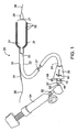
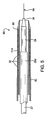
次に、図1を参照すると、末端部を断面で表わしたステント移送カテーテル装置20が示されている。一実施形態では、カテーテル装置20は、前に参照によって組み入れられた米国特許出願第10/637713号に記載されているステント移送カテーテルと類似しているが、複数のステント・セグメント32が配置されたシャトル21の追加の特徴を含む。この場合も、複数のセグメント32を持つ1つのステント、それぞれ複数のセグメント32を持つ複数のステント、複数の非セグメント化されたステントなどが、シャトル21上に設けられる。一般に、ステント移送カテーテル20は、軸27の上側に摺動自在に設けられたシース25を備えるカテーテル本体22を含むことが好ましい。拡張可能な部材24、好ましくは、膨脹可能なバルーン(膨脹した形態で図示されている)は、軸27に付けられていて、軸27に対してシース25を引っ込めることで露出する。別法として、拡張可能な部材は、拡張可能な編組物、拡張可能なケージ(かご)、拡張可能なMallecott構造物、自己拡張する構造物(形状記憶ケージを含む)などのような、内腔内カテーテル技術において知られている機械、油圧、電気などで拡張できる他の様々な構造物のいずれでもよい。この装置を前進させている間、血管への外傷を減らすために、柔かいエラストマ材料から成るテーパー付きノーズコーン28を、拡張可能な部材24の末端側に付けることができる。ステント・セグメント32がシャトル21上に設けられ、さらに、シャトルが、拡張可能な部材24上側に設けられて、拡張可能な部材24といっしょに拡張するが、その場合、ステント・セグメント32は、一般に、同軸で、かつ摺動自在に軸27の上側に受け止められている。いくつかの実施形態では、ガイドワイヤ・チューブ34が、シース25内で、拡張可能な部材24の基部側のガイドワイヤ・チューブ出口35を通って摺動自在に配置されている。ガイドワイヤ36は、ガイドワイヤ・チューブ34、拡張可能な部材24、ノーズコーン28を通って、摺動自在に設けられて、その末端側に延びている。ガイドワイヤを軸27全体に通す他の設計も、本発明の範囲内にある。
Referring now to FIG. 1, there is shown a stent
ハンドルまたはハブ38が、シース25の近位端23に取り付けられていて、以下に述べられる目的で摺動自在に取り付けられたアクチュエータ40を含む。アダプタ42は、ハンドル38の近位端に取り付けられていて、軸27を摺動自在に配置させているカテーテル・ポート44を備えている。フラッシュ・ポート48が、アダプタ42の側面に取り付けられていて、生理的食塩水などの流体を、フラッシュ・ポート48を介してカテーテル本体22の内部に導入することができる。カテーテル・ポート44中の環状シール(図示されてない)は、軸27の周りを封止して、流体がカテーテル・ポート44から漏れないようにする。任意選択で、ハンドル38に対して軸27をロックするために、ねじ付きカラーなどのクランプ(図示されてない)をカテーテル・ポート44に取り付けることができる。アダプタ42は、ハンドル38とは別に図示されているが、これらの構造物を互いに一体にすることもある。
A handle or
軸27は、近位端50を持ち、その近位端50には膨脹アダプタ52(これも、ハンドル38と一体に形成されることもある)が取り付けられている。膨脹アダプタ52は、膨脹装置54に流体結合されるように構成されている。膨脹装置54は、Santa Clara,CAのAdvanced Cardiovascular Systemsから入手できる商品名「IndeflatorTM」のもとに販売されているような任意の市販バルーン膨脹装置でよい。膨脹アダプタ52は、拡張可能な部材24を膨脹させることができるように、軸27中の膨脹管腔を介して、拡張可能な部材24と流体連通している。ステント自体の様々な実施形態だけでなく、分散型ステントを移送する装置と方法もさらに詳しく説明するために、前に参照によって組み入れられた米国特許出願第10/412714号と米国特許出願第10/637713号を参照する。
The
上記の通り、また以下でさらに詳しく説明されるように、ステント移送カテーテル20の形態は、いくつかの代替形式のいずれでもよい。例えば、図2では、シャトル21は、シース25a外側で、かつ拡張可能な部材24の周りに設けられる。代替実施形態では、シャトル21は、シース25bの内側に設けられる。これらの実施形態のいずれにおいても、シャトル21は、おそらくカテーテル20のほぼ全長にわたって延びている比較的に長い管状部材から成っているか、あるいは、カテーテル20の末端部だけに沿って設けられた管状部材である。様々なシャトル21は、軸27および/またはシース25に対して、固定されているか、あるいは、摺動できる。ステント30またはステント・セグメント32は、様々な実施形態において、シャトル21上に固定されるやり方で、または摺動自在なやり方で取り付けられる。その場合、摺動自在な実施形態は、ステント・セグメント32を前進させるステント押し部材を含むことが多い。それゆえ、図1は、ステント移送装置の模範的な実施形態を1つだけ示しており、本発明の範囲を限定するものと解してはならない。
As described above and as described in more detail below, the configuration of the
ステント・セグメント32は、前に参照によって組み入れられた米国特許出願第10/637713号と、参照によって本明細書に組み入れられた2003年1月17日出願の米国特許出願第60/440839号(Attorney Docket No.21629−000500)にさらに詳しく説明されている。一実施形態では、例えば、それぞれのステント・セグメントは、長さが約2〜8mmであり、また、10〜50個までのステント・セグメントを、シャトル21上に、端と端を接して、一列に配置している。ステント・セグメント32は、互いにじかに接触していてもいが、ただし、好ましくは、ステント・セグメント32に、互いに充分な間隔を置いて、それぞれのステント・セグメント32が、隣り合ったステント・セグメント(1つまたは複数)32のどれにも妨げられずに拡張できるようにする。別法として、隣り合ったステント・セグメント32の間に、別々のスペーシング要素を設けてもよい。このようなスペーシング要素は、ステント・セグメント32とともに、血管の中で展開できるように、塑性変形できるか、あるいは自己拡張できるが、ただし、別法として、ステントの展開後にシャトル21上にとどまるように構成されてもよく、例えば、このようなスペーシング要素には、バルーン部材70とともに伸縮自在に拡張し、またシャトル21が収縮すると、それらの拡張していない形状に弾力的に戻る弾性リングが含まれる。
ステント・セグメント32は、好ましくは、血管内で所望の直径まで拡張すると、拡張可能な部材24により塑性変形できるように、可鍛金属である。別法として、ステント・セグメント32は、シース25を引っ込めることで、血管中に離されることで自己拡張するように、Nitinolなどの弾性または超弾性の形状記憶材料で形成されてもよい。ステント・セグメント32はまた、ポリマーまたは他の適切な生体親和性材料から構成されてもよい。自己拡張する実施形態では、拡張可能な部材24は、ステントの展開前に病変を事前拡張させるために、あるいは、自己拡張するステント・セグメントの拡張を増大させるために使用される。好ましい実施形態では、ステント・セグメント32は、Rapamycin、Everolimus、Paclitaxel、また、Rapamycin、Everolimus、またはPaclitaxelのアナローグ、誘導剤、プロドラッグ、あるいは、他の適切な薬剤(好ましくは、生体侵食可能なポリマー・キャリア(bioerodable polymeric carrier)で運ばれるもの)のように、再狭窄を抑制する薬でコーティングされている。別法として、ステント・セグメント32は、抗生物質、血栓溶解剤、抗血栓症剤、抗炎症剤、細胞毒性薬剤、抗増殖性薬剤、血管拡張剤、遺伝子治療薬剤、放射性薬剤、免疫抑制剤、化学療法薬剤、幹細胞などの他のタイプの薬および治療物質でコーティングされることもある。このような物質は、ステント・セグメント32の表面の全部または一部にわたってコーティングされるか、あるいは、ステント・セグメント32は、このような物質を被着できる開口、穴、溝、または他の特徴要素を含む。
The
ステント・セグメント32は、前に参照によって組み入れられた米国特許出願第60/440839号に記載されているものを含め、様々な形態を持つことができる。ステント・セグメント32は、好ましくは、まったく相互結合なしに、互いに完全に分かれていることであるが、ただし、別法として、隣り合った2つ以上のセグメントの間に、これらのセグメントを互いに曲げることができるような継手を持っていてもよい。さらに他の別法として、隣り合った1つまたは複数のステント・セグメント32は、参照によって本明細書に組み入れられた2002年11月27日出願の米国特許出願第10/306,813号(Attorney Docket No.21629−000320)に記載されているように、展開前または展開時に切り離される分離可能または折れやすい継手により結合されてもよい。
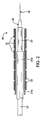
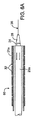
次に図2を参照すると、ステント移送カテーテル60の一実施形態の末端部が示されている。この場合も、ステント移送カテーテル60は、カテーテル軸27、拡張可能な部材24、シース25a、ノーズコーン28を含み、また、ガイドワイヤ36を通すようにすることが好ましい。ステント・セグメント32は、シャトル21aに沿って設けられ、また、この実施形態では、シャトル21aは、シース25aと拡張可能な部材24に沿って設けられている。
Referring now to FIG. 2, the distal end of one embodiment of the
シャトル21aは、任意の適切な材料または材料の組合せから構成され、また、任意の適切な長さ、内径、厚さなどを持つ。拡張可能な部材24がシャトル21aを拡張させて、ステント・セグメント32を拡張させ、かつ展開させることができるように、一般に、シャトル21aの少なくとも一部は拡張可能である。したがって、シャトル21は、その全長に沿って、あるいは、遠位端付近で、その長さの一部に沿ってのみ拡張できるようになっていてもよい。シャトル21aの拡張可能な部分は、拡張可能な部材24のものに類似する材料、あるいは代替材料から構成されてもよい。いくつかの実施形態では、例えば、シャトル21aの少なくとも一部は、PebaxまたはNylonなどの半可撓性のポリマーを含んでもよく、これは、拡張後に、その拡張していない形状に弾力的に戻るように構成されている。シャトル21aの拡張していない基部側部分が1つ含まれる場合には、その部分は、ポリイミド、PTFE、FEP、またはPebaxなどのポリマーからできているか、あるいは、他の適切な任意の材料を含んでいる。シース25aの軸方向の摺動を向上させるために、シャトル21aは、摩擦を減らすか、または摩擦を最小限に抑える材料でできており、かつ/または、摩擦を減らす被覆で覆われる。
The
シース25aは、拡張していない形態にあるときに、拡張可能な部材24を囲うように構成された末端部を持っている。この末端部は、好ましくはガイドワイヤ・チューブ出口の場所に揃えられた接合個所の基部側に延びており、その場合、末端部は、ハンドル38の基部側に延びている基部に接合されている(図1)。一実施形態では、この末端部は、約15〜35cmの長さを持ち、また、この基部は、約100〜125cmの長さを持っている。基部は、様々な生体親和性のポリマーまたは金属(好ましくは、ステンレス鋼またはNitinolである)で構成される。末端部は、PTFE、FEP、ポリイミド、またはPebaxなどのポリマーであり、また、拡張可能な部材24が拡張するときに、半径方向の拡張に耐えるように、好ましくは、金属製またはポリマー製の編組物で補強される。
The
基部は、撓み性を最大にし、かつ外形を最小限に抑えるためだけでなく、血管内腔内に、ガイドワイヤ・チューブの追加幅を受け入れるためにも、末端部よりも小さい横断寸法を持っていることが望ましい。一実施形態では、例えば、末端部は、約1.0〜1.5mmの外径を持ち、また、基部は、約0.7〜1.0mmの外径を持つ。基部と末端部との接合個所には、ガイドワイヤ・チューブ出口を形成する、基部側に面する三日月形開口が、これら2つの管状部材の間に形成される。この三日月形開口中の余分の空間には、接着剤などの充填剤が詰められる。 The base has a smaller transverse dimension than the distal end, not only to maximize flexibility and minimize profile, but also to accommodate the additional width of the guidewire tube within the vessel lumen It is desirable. In one embodiment, for example, the distal end has an outer diameter of about 1.0 to 1.5 mm and the base has an outer diameter of about 0.7 to 1.0 mm. At the junction between the base and the distal end, a crescent-shaped opening facing the base that forms the guidewire tube outlet is formed between the two tubular members. The extra space in the crescent shaped opening is filled with a filler such as an adhesive.
いくつかの実施形態では、シャトル21は、1つまたは複数のカテーテル構成要素に対して軸方向に移動させるために、カテーテル60と摺動自在に結合されている。シース25aが基部側に引っ込められて、拡張可能な部材24の一部を露出させる。次に、拡張可能な部材24(拡張していない形態で示されている)が拡張して、シャトル21aに接触し、かつそれを拡張させ、さらに、シャトル21aが、選択された数のステント・セグメント32を拡張させて、展開させる。このようにして、ステント・セグメント32は、一度に1つ、あるいはグループで拡張し、展開して、所望の長さのステント展開を実現することができる。シース25aをさらに基部側に引っ込めると、さらに多くの拡張可能な部材が露出して、さらに多くのシャトル21aが拡張し、また、追加的なステント・セグメント32が拡張し、展開する。カテーテル60はまた、シャトル21に対して引っ込められて、拡張可能な部材24を、追加的なステント・セグメント32に揃えることができる。他の実施形態では、シャトル21aを移送カテーテル60に固定させて、カテーテル軸27、拡張可能な部材24などに対して、軸方向に摺動しないようにしてもよい。
In some embodiments,
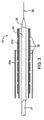
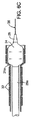
次に、図3を参照すると、ステント移送カテーテル70の代替実施形態の末端部が示されている。この実施形態では、シャトル21bがシース25b内に設けられ、また、ステント・セグメント32は、シャトル21bに沿って設けられ、さらに、拡張可能な部材24は、シャトル21b内に設けられる。このような実施形態では、シース25bが基部側に引っ込められることで、拡張可能な部材24、シャトル21b、ステント・セグメント32を拡張させることができる。別法として、シャトル21bと拡張可能な部材24を、シース24から末端側に前進させるようにしてもよい。前述の実施形態と同様に、拡張可能な部材24、シャトル21b、ステント・セグメント32がシース25bから露出すると、それらは、拡張して、血管内腔または他の内腔内にステント・セグメント32を展開させることができる。
Referring now to FIG. 3, the distal end of an alternative embodiment of the
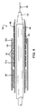
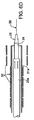
次に、図4に移る。ステント移送カテーテル80の他の実施形態の遠位端が、この場合も、そのシャトル21cが、シース25c内に配置させられている。しかしながら、この実施形態では、ステント・セグメント32は、シャトル21cに沿って、摺動自在に設けられている。このような実施形態では、ステント・セグメント32は、基部側に配置されたステント押し部材82を用いて、シャトル21cに沿って前進させられる。ステント押し部材82は、様々な生体親和性のポリマーまたは金属(好ましくは、ステンレス鋼またはNitinolである)で構成される。ステント・セグメント32が、進みすぎて、シャトルの遠位端から落ちないようにするために、シャトル21cに、環状隆起86または他の止め部材を付けて、最も末端側のステント・セグメント32を止める働きをさせる。このような実施形態はまた、シース25cを通過するステント・セグメント32の数を医師がよりよく調整できるようにするために、シース25cの内面に設けられた1つまたは複数の弁84も含む。このような弁は、前に参照によって組み入れられた同時係属中の米国特許出願第10/412714号に記載されている。さらに、弁84により、医師は、ステント・セグメント32をシース25c内に引っ込めることができ、それにより、隣り合ったステント・セグメント32の相互の妨害なしに展開させるために、ステント・セグメント32間の適切な間隔をもたらす。
Next, the process moves to FIG. The distal end of another embodiment of the stent delivery catheter 80 again has its shuttle 21c disposed within the
次に、他の実施形態において、図5を参照すると、ステント移送カテーテル90は、シース25dの外側に設けられたシャトル21d上に、軸方向に摺動自在なステント・セグメント32を含む。この場合も、ステント押し部材82が、カテーテル装置90に含まれ、また、シャトル21dが、環状隆起86を含む。シース25dは、拡張可能な部材24の所望の長さを選択的に露出させるために、拡張可能な部材24の上側で軸方向に摺動自在である。
Next, in another embodiment, referring to FIG. 5, the
次に、図6A〜図6Dを参照すると、ステント・セグメントを移送方法が示されているが、ただし、分かりやすくするために、血管内腔も、他の内腔も示されていない。一般に、ステント移送カテーテル60を、患者の血管内腔または他の内腔を通って、所望の場所まで前進させて、ステント・セグメント32を移送する。この地点では、図6Aの2つの基部側に向いた矢印で示されるように、シース25aを基部側に引っ込めて、シャトル21A内の拡張可能な部材24の少なくとも一部を露出させる。次に、露出した拡張可能な部材24を、図6Bと図6Cに示されるように拡張させる。このような拡張の際、拡張可能な部材24は、シャトル21aの拡張可能な部分に接触して、それを拡張させ、さらに、この拡張可能な部分が、図6Cに示されるように、1つまたは複数のステント・セグメント32を拡張させる。次に、拡張可能な部材24を収縮させても、ステント・セグメント32は、図6Dに示されるように、拡張した状態にあって、所定の位置にとどまる。しかしながら、シャトル21aは、その元の形状に戻る。次に、医師は、移送カテーテル60を元に戻し、シース25aと拡張可能な部材24をさらに基部に引っ込めて、かつ、拡張可能な部材24とシャトル21aを拡張させて、追加的なステント・セグメント32を展開させることができる。処理が終了すると、医師は、シース25aを末端側に前進させて、拡張可能な部材24を覆う。この方法はさらに、ステント押し部材を用いてステント・セグメント32を前進させる処置、シャトル21aを摺動させる処置、図4のカテーテルの実施形態を利用して、弁を使ってステントの前進を制御する処置を含む。この方法の様々な実施形態は、本発明の範囲から逸脱することなく、ステップを追加するか、取り去るか、あるいは、その代りをすることで、利用できる。
Referring now to FIGS. 6A-6D, a method for delivering a stent segment is shown, but for the sake of clarity, neither vessel lumen nor other lumens are shown. In general, the
上記のものは、本発明の好ましい実施形態を完全に説明したものであるが、併記の特許請求の範囲で定められる本発明の範囲から逸脱しなければ、様々な代替、追加、変更、改良を行うことができる。 While the above is a complete description of the preferred embodiment of the present invention, various alternatives, additions, modifications and improvements may be made without departing from the scope of the invention as defined in the appended claims. It can be carried out.
20 ステント移送カテーテル装置、21 シャトル、22 カテーテル本体、24 拡張可能な部材、25 シース、27 軸、32 ステント・セグメント、36 ガイドワイヤ 20 Stent Transfer Catheter Device, 21 Shuttle, 22 Catheter Body, 24 Expandable Member, 25 Sheath, 27 Axis, 32 Stent Segment, 36 Guidewire
Claims (34)
近位端と遠位端を持つカテーテル軸と、
前記遠位端付近で前記カテーテル軸と結合されている拡張可能な部材と、
前記カテーテル軸と前記拡張可能な部材の少なくとも一部の上側に設けられた軸方向に動けるシースと、
前記カテーテル軸と前記拡張可能な部材の少なくとも一部の上側に同軸状に設けられて、少なくとも一部が半径方向に拡張可能であるシャトルと、
前記シャトルに沿って設けられた複数のステント・セグメントと、
を備え、
前記シースを、軸方向に前記カテーテル軸の前記近位端に向けて移動させると、前記拡張可能な部材の少なくとも一部が拡張して前記シャトルに当たり、シャトルを半径方向に拡張させ、前記複数のステント・セグメントの少なくとも1つが拡張することを特徴とするステント移送装置。 A stent delivery device for delivering a plurality of stent segments to a treatment location,
A catheter shaft having a proximal end and a distal end;
An expandable member coupled to the catheter shaft near the distal end;
An axially movable sheath provided above at least a portion of the catheter shaft and the expandable member;
A shuttle provided coaxially above at least a portion of the catheter shaft and the expandable member and at least a portion of which is radially expandable;
A plurality of stent segments provided along the shuttle;
With
When the sheath is moved axially toward the proximal end of the catheter shaft, at least a portion of the expandable member expands to hit the shuttle, causing the shuttle to expand radially, and A stent delivery device, wherein at least one of the stent segments expands.
近位端と遠位端を持つカテーテル軸と、
前記遠位端付近で前記カテーテル軸と結合されている拡張可能な部材と、
前記カテーテル軸と前記拡張可能な部材の少なくとも一部の上側に設けられた軸方向に動けるシースと、
前記カテーテル軸と前記拡張可能な部材の少なくとも一部の上側に設けられて、少なくとも一部が半径方向に拡張可能であるシャトルと、
前記シャトルに沿って摺動自在に設けられた複数のステント・セグメントと、
前記ステント・セグメントを前記シャトルに沿って末端側に前進させるために、前記シャトル上で前記複数のステント・セグメントの基部側に設けられたステント押し部材と、
を備え、
前記シースを、軸方向に前記カテーテル軸の前記近位端に向けて移動させると、前記拡張可能な部材の少なくとも一部が露出し、それにより、前記拡張可能な部材を拡張させて前記シャトルに当たり、前記シャトルを半径方向に拡張させることができ、したがって、前記複数のステント・セグメントの少なくとも1つが拡張することを特徴とするステント移送装置。 A stent delivery device for delivering a plurality of stent segments to a treatment location,
A catheter shaft having a proximal end and a distal end;
An expandable member coupled to the catheter shaft near the distal end;
An axially movable sheath provided above at least a portion of the catheter shaft and the expandable member;
A shuttle provided above at least a portion of the catheter shaft and the expandable member and at least a portion of which is radially expandable;
A plurality of stent segments slidably provided along the shuttle;
A stent push member provided on the proximal side of the plurality of stent segments on the shuttle to advance the stent segment distally along the shuttle;
With
Moving the sheath axially toward the proximal end of the catheter shaft exposes at least a portion of the expandable member, thereby expanding the expandable member and hitting the shuttle. The stent delivery device, wherein the shuttle can be radially expanded, and thus at least one of the plurality of stent segments expands.
ステント移送カテーテル装置の末端部を前記治療場所に配置するステップと、
前記カテーテル装置のシースを基部側に移動させて、前記カテーテル装置上の拡張可能な部材の少なくとも一部を露出させ、それにより、前記露出した拡張可能な部材を拡張させて、前記カテーテル装置の拡張可能なシャトルに当てて、前記複数のステント・セグメントの少なくとも1つを展開させるステップと、
を含むことを特徴とする方法。 A method of transferring a plurality of stent segments to a treatment location,
Placing a distal end of a stent delivery catheter device at the treatment site;
The catheter device sheath is moved proximally to expose at least a portion of the expandable member on the catheter device, thereby expanding the exposed expandable member to expand the catheter device. Deploying at least one of the plurality of stent segments against a possible shuttle;
A method comprising the steps of:
展開されることを望むステント・セグメントの数を選択するステップと、
前記シースを、前記カテーテル装置に沿って或る位置に移動させて、前記選択された数のステント・セグメントを展開させるステップと、
を含むことを特徴とする請求項22に記載の方法。 Deploying the first plurality of stent segments comprises:
Selecting the number of stent segments desired to be deployed;
Moving the sheath to a position along the catheter device to deploy the selected number of stent segments;
23. The method of claim 22, comprising:
ステント移送カテーテル装置の末端部を前記治療場所に配置するステップと、
前記カテーテル装置のシースを基部側に移動させて、前記カテーテル装置の拡張可能な部材の少なくとも一部を露出させ、それにより、前記露出した拡張可能な部材を拡張させて、前記カテーテル装置の拡張可能なシャトルに当てて、前記複数のステントの少なくとも第1のステントを展開させるステップと、
を含むことを特徴とする方法。 A method of transferring a plurality of stents to a treatment site,
Placing a distal end of a stent delivery catheter device at the treatment site;
The catheter device sheath is moved proximally to expose at least a portion of the expandable member of the catheter device, thereby expanding the exposed expandable member to expand the catheter device. Applying a shuttle to deploy at least a first stent of the plurality of stents;
A method comprising the steps of:
Applications Claiming Priority (2)
| Application Number | Priority Date | Filing Date | Title |
|---|---|---|---|
| US10/686,507 US20050080475A1 (en) | 2003-10-14 | 2003-10-14 | Stent delivery devices and methods |
| PCT/US2004/031853 WO2005037130A2 (en) | 2003-10-14 | 2004-09-28 | Stent delivery devices and methods |
Publications (2)
| Publication Number | Publication Date |
|---|---|
| JP2007508111A true JP2007508111A (en) | 2007-04-05 |
| JP2007508111A5 JP2007508111A5 (en) | 2007-10-04 |
Family
ID=34423295
Family Applications (1)
| Application Number | Title | Priority Date | Filing Date |
|---|---|---|---|
| JP2006535519A Pending JP2007508111A (en) | 2003-10-14 | 2004-09-28 | Apparatus and method for delivering a stent |
Country Status (6)
| Country | Link |
|---|---|
| US (1) | US20050080475A1 (en) |
| EP (1) | EP1684843A2 (en) |
| JP (1) | JP2007508111A (en) |
| AU (1) | AU2004281662A1 (en) |
| CA (1) | CA2538165A1 (en) |
| WO (1) | WO2005037130A2 (en) |
Families Citing this family (52)
| Publication number | Priority date | Publication date | Assignee | Title |
|---|---|---|---|---|
| US7018401B1 (en) | 1999-02-01 | 2006-03-28 | Board Of Regents, The University Of Texas System | Woven intravascular devices and methods for making the same and apparatus for delivery of the same |
| EP1258230A3 (en) * | 2001-03-29 | 2003-12-10 | CardioSafe Ltd | Balloon catheter device |
| GB0121980D0 (en) | 2001-09-11 | 2001-10-31 | Cathnet Science Holding As | Expandable stent |
| US8080048B2 (en) | 2001-12-03 | 2011-12-20 | Xtent, Inc. | Stent delivery for bifurcated vessels |
| US7892273B2 (en) | 2001-12-03 | 2011-02-22 | Xtent, Inc. | Custom length stent apparatus |
| US7137993B2 (en) | 2001-12-03 | 2006-11-21 | Xtent, Inc. | Apparatus and methods for delivery of multiple distributed stents |
| US7147656B2 (en) | 2001-12-03 | 2006-12-12 | Xtent, Inc. | Apparatus and methods for delivery of braided prostheses |
| US7351255B2 (en) | 2001-12-03 | 2008-04-01 | Xtent, Inc. | Stent delivery apparatus and method |
| US7309350B2 (en) | 2001-12-03 | 2007-12-18 | Xtent, Inc. | Apparatus and methods for deployment of vascular prostheses |
| US20030135266A1 (en) * | 2001-12-03 | 2003-07-17 | Xtent, Inc. | Apparatus and methods for delivery of multiple distributed stents |
| US7294146B2 (en) | 2001-12-03 | 2007-11-13 | Xtent, Inc. | Apparatus and methods for delivery of variable length stents |
| US7182779B2 (en) | 2001-12-03 | 2007-02-27 | Xtent, Inc. | Apparatus and methods for positioning prostheses for deployment from a catheter |
| US7270668B2 (en) * | 2001-12-03 | 2007-09-18 | Xtent, Inc. | Apparatus and methods for delivering coiled prostheses |
| US20040186551A1 (en) | 2003-01-17 | 2004-09-23 | Xtent, Inc. | Multiple independent nested stent structures and methods for their preparation and deployment |
| US7241308B2 (en) | 2003-06-09 | 2007-07-10 | Xtent, Inc. | Stent deployment systems and methods |
| US7192440B2 (en) * | 2003-10-15 | 2007-03-20 | Xtent, Inc. | Implantable stent delivery devices and methods |
| US7326236B2 (en) | 2003-12-23 | 2008-02-05 | Xtent, Inc. | Devices and methods for controlling and indicating the length of an interventional element |
| US7323006B2 (en) | 2004-03-30 | 2008-01-29 | Xtent, Inc. | Rapid exchange interventional devices and methods |
| US20050228477A1 (en) * | 2004-04-09 | 2005-10-13 | Xtent, Inc. | Topographic coatings and coating methods for medical devices |
| US20050288766A1 (en) | 2004-06-28 | 2005-12-29 | Xtent, Inc. | Devices and methods for controlling expandable prostheses during deployment |
| US8317859B2 (en) | 2004-06-28 | 2012-11-27 | J.W. Medical Systems Ltd. | Devices and methods for controlling expandable prostheses during deployment |
| US20060015170A1 (en) * | 2004-07-16 | 2006-01-19 | Jones Ryan A | Contrast coated stent and method of fabrication |
| US20060069424A1 (en) * | 2004-09-27 | 2006-03-30 | Xtent, Inc. | Self-constrained segmented stents and methods for their deployment |
| US7402168B2 (en) * | 2005-04-11 | 2008-07-22 | Xtent, Inc. | Custom-length stent delivery system with independently operable expansion elements |
| US8641746B2 (en) * | 2005-05-31 | 2014-02-04 | J.W. Medical Systems Ltd. | In situ stent formation |
| US8157851B2 (en) * | 2005-06-08 | 2012-04-17 | Xtent, Inc. | Apparatus and methods for deployment of multiple custom-length prostheses |
| US20070179587A1 (en) * | 2006-01-30 | 2007-08-02 | Xtent, Inc. | Apparatus and methods for deployment of custom-length prostheses |
| AU2007227000A1 (en) * | 2006-03-20 | 2007-09-27 | Xtent, Inc. | Apparatus and methods for deployment of linked prosthetic segments |
| HRP20060149B1 (en) * | 2006-04-19 | 2008-11-30 | Institut "Ruđer Bošković" | Intelligent sequential illuminator photodynamic therapy |
| US20070281117A1 (en) * | 2006-06-02 | 2007-12-06 | Xtent, Inc. | Use of plasma in formation of biodegradable stent coating |
| US20080269865A1 (en) * | 2006-08-07 | 2008-10-30 | Xtent, Inc. | Custom Length Stent Apparatus |
| KR20130095317A (en) | 2006-10-22 | 2013-08-27 | 이데브 테크놀로지스, 아이엔씨. | Devices and methods for stent advancement |
| BRPI0717392A2 (en) | 2006-10-22 | 2013-10-15 | Idev Technologies Inc | METHODS FOR FIXING WIRE END AND RESULTING DEVICES |
| US20080199510A1 (en) | 2007-02-20 | 2008-08-21 | Xtent, Inc. | Thermo-mechanically controlled implants and methods of use |
| US8486132B2 (en) | 2007-03-22 | 2013-07-16 | J.W. Medical Systems Ltd. | Devices and methods for controlling expandable prostheses during deployment |
| US8715332B2 (en) * | 2008-01-15 | 2014-05-06 | Boston Scientific Scimed, Inc. | Expandable stent delivery system with outer sheath |
| US9101503B2 (en) | 2008-03-06 | 2015-08-11 | J.W. Medical Systems Ltd. | Apparatus having variable strut length and methods of use |
| US9061119B2 (en) | 2008-05-09 | 2015-06-23 | Edwards Lifesciences Corporation | Low profile delivery system for transcatheter heart valve |
| US8828071B2 (en) | 2008-09-25 | 2014-09-09 | Advanced Bifurcation Systems, Inc. | Methods and systems for ostial stenting of a bifurcation |
| CN102215780B (en) | 2008-09-25 | 2015-10-14 | 高级分支系统股份有限公司 | Part crimped stent |
| US11298252B2 (en) | 2008-09-25 | 2022-04-12 | Advanced Bifurcation Systems Inc. | Stent alignment during treatment of a bifurcation |
| US8821562B2 (en) | 2008-09-25 | 2014-09-02 | Advanced Bifurcation Systems, Inc. | Partially crimped stent |
| WO2011119883A1 (en) | 2010-03-24 | 2011-09-29 | Advanced Bifurcation Systems, Inc. | Stent alignment during treatment of a bifurcation |
| CN109363807B (en) | 2010-03-24 | 2021-04-02 | 高级分支系统股份有限公司 | System and method for treating a bifurcation |
| EP2549958A4 (en) | 2010-03-24 | 2016-09-14 | Advanced Bifurcation Systems Inc | Methods and systems for treating a bifurcation with provisional side branch stenting |
| US9023095B2 (en) | 2010-05-27 | 2015-05-05 | Idev Technologies, Inc. | Stent delivery system with pusher assembly |
| EP2672925B1 (en) | 2011-02-08 | 2017-05-03 | Advanced Bifurcation Systems, Inc. | Multi-stent and multi-balloon apparatus for treating bifurcations |
| EP3449879B1 (en) | 2011-02-08 | 2020-09-23 | Advanced Bifurcation Systems Inc. | System for treating a bifurcation with a fully crimped stent |
| US20120290065A1 (en) * | 2011-05-12 | 2012-11-15 | Boston Scientific Scimed Inc. | Pre-Positioned Anastomosis Device and Related Methods of Use |
| EP4299086A2 (en) | 2017-04-10 | 2024-01-03 | LimFlow GmbH | Devices for treating lower extremity vasculature |
| CA3112353A1 (en) | 2018-10-09 | 2020-04-16 | Limflow Gmbh | Devices and methods for catheter alignment |
| CN114929163A (en) | 2019-11-01 | 2022-08-19 | 林弗洛公司 | Device and method for increasing blood perfusion to distal extremities |
Citations (3)
| Publication number | Priority date | Publication date | Assignee | Title |
|---|---|---|---|---|
| JPH10503411A (en) * | 1995-05-25 | 1998-03-31 | メドトロニック・インコーポレーテッド | Stent assembly and method of using the same |
| JPH1170170A (en) * | 1997-04-21 | 1999-03-16 | Advanced Cardeovascular Syst Inc | Sheath for stent feeding system and use method therefor |
| US20030135266A1 (en) * | 2001-12-03 | 2003-07-17 | Xtent, Inc. | Apparatus and methods for delivery of multiple distributed stents |
Family Cites Families (92)
| Publication number | Priority date | Publication date | Assignee | Title |
|---|---|---|---|---|
| US4069825A (en) * | 1976-01-28 | 1978-01-24 | Taichiro Akiyama | Surgical thread and cutting apparatus for the same |
| US4564014A (en) * | 1980-01-30 | 1986-01-14 | Thomas J. Fogarty | Variable length dilatation catheter apparatus and method |
| US4512338A (en) * | 1983-01-25 | 1985-04-23 | Balko Alexander B | Process for restoring patency to body vessels |
| US4580568A (en) * | 1984-10-01 | 1986-04-08 | Cook, Incorporated | Percutaneous endovascular stent and method for insertion thereof |
| US5102417A (en) * | 1985-11-07 | 1992-04-07 | Expandable Grafts Partnership | Expandable intraluminal graft, and method and apparatus for implanting an expandable intraluminal graft |
| US4733665C2 (en) * | 1985-11-07 | 2002-01-29 | Expandable Grafts Partnership | Expandable intraluminal graft and method and apparatus for implanting an expandable intraluminal graft |
| US5350395A (en) * | 1986-04-15 | 1994-09-27 | Yock Paul G | Angioplasty apparatus facilitating rapid exchanges |
| US4988356A (en) * | 1987-02-27 | 1991-01-29 | C. R. Bard, Inc. | Catheter and guidewire exchange system |
| US5092877A (en) * | 1988-09-01 | 1992-03-03 | Corvita Corporation | Radially expandable endoprosthesis |
| CA1322628C (en) * | 1988-10-04 | 1993-10-05 | Richard A. Schatz | Expandable intraluminal graft |
| US4994066A (en) * | 1988-10-07 | 1991-02-19 | Voss Gene A | Prostatic stent |
| US4994069A (en) * | 1988-11-02 | 1991-02-19 | Target Therapeutics | Vaso-occlusion coil and method |
| US5292331A (en) * | 1989-08-24 | 1994-03-08 | Applied Vascular Engineering, Inc. | Endovascular support device |
| IE73670B1 (en) * | 1989-10-02 | 1997-07-02 | Medtronic Inc | Articulated stent |
| US5013318A (en) * | 1990-07-31 | 1991-05-07 | Special Devices Incorporated | Medical instrument for measuring depth of fastener hold in bone |
| CA2052981C (en) * | 1990-10-09 | 1995-08-01 | Cesare Gianturco | Percutaneous stent assembly |
| CA2060067A1 (en) * | 1991-01-28 | 1992-07-29 | Lilip Lau | Stent delivery system |
| US5135535A (en) * | 1991-06-11 | 1992-08-04 | Advanced Cardiovascular Systems, Inc. | Catheter system with catheter and guidewire exchange |
| US5490837A (en) * | 1991-07-05 | 1996-02-13 | Scimed Life Systems, Inc. | Single operator exchange catheter having a distal catheter shaft section |
| CA2380683C (en) * | 1991-10-28 | 2006-08-08 | Advanced Cardiovascular Systems, Inc. | Expandable stents and method for making same |
| US5507771A (en) * | 1992-06-15 | 1996-04-16 | Cook Incorporated | Stent assembly |
| US5312415A (en) * | 1992-09-22 | 1994-05-17 | Target Therapeutics, Inc. | Assembly for placement of embolic coils using frictional placement |
| US5336178A (en) * | 1992-11-02 | 1994-08-09 | Localmed, Inc. | Intravascular catheter with infusion array |
| US5607463A (en) * | 1993-03-30 | 1997-03-04 | Medtronic, Inc. | Intravascular medical device |
| US5735892A (en) * | 1993-08-18 | 1998-04-07 | W. L. Gore & Associates, Inc. | Intraluminal stent graft |
| US5607444A (en) * | 1993-12-02 | 1997-03-04 | Advanced Cardiovascular Systems, Inc. | Ostial stent for bifurcations |
| SI0669114T1 (en) * | 1994-02-25 | 1999-02-28 | Robert E. Fischell | Stent having a multiplicity of closed circular structures |
| US5453090A (en) * | 1994-03-01 | 1995-09-26 | Cordis Corporation | Method of stent delivery through an elongate softenable sheath |
| US5514093A (en) * | 1994-05-19 | 1996-05-07 | Scimed Life Systems, Inc. | Variable length balloon dilatation catheter |
| DE4418336A1 (en) * | 1994-05-26 | 1995-11-30 | Angiomed Ag | Stent for widening and holding open receptacles |
| US5723003A (en) * | 1994-09-13 | 1998-03-03 | Ultrasonic Sensing And Monitoring Systems | Expandable graft assembly and method of use |
| US5735869A (en) * | 1994-11-30 | 1998-04-07 | Schneider (Europe) A.G. | Balloon catheter and stent delivery device |
| FR2733682B1 (en) * | 1995-05-04 | 1997-10-31 | Dibie Alain | ENDOPROSTHESIS FOR THE TREATMENT OF STENOSIS ON BIFURCATIONS OF BLOOD VESSELS AND LAYING EQUIPMENT THEREFOR |
| EP0830109B1 (en) * | 1995-06-08 | 2003-10-15 | Ave Galway Limited | Bifurcated endovascular stent |
| JP3467916B2 (en) * | 1995-07-10 | 2003-11-17 | 松下電器産業株式会社 | Transmission / reception method |
| JP3725919B2 (en) * | 1995-09-26 | 2005-12-14 | キーパー株式会社 | Resin CVJ boots |
| US6042605A (en) * | 1995-12-14 | 2000-03-28 | Gore Enterprose Holdings, Inc. | Kink resistant stent-graft |
| US6878161B2 (en) * | 1996-01-05 | 2005-04-12 | Medtronic Vascular, Inc. | Stent graft loading and deployment device and method |
| EP0795304B1 (en) * | 1996-03-10 | 2004-05-19 | Terumo Kabushiki Kaisha | Implanting stent |
| US6334871B1 (en) * | 1996-03-13 | 2002-01-01 | Medtronic, Inc. | Radiopaque stent markers |
| US5709701A (en) * | 1996-05-30 | 1998-01-20 | Parodi; Juan C. | Apparatus for implanting a prothesis within a body passageway |
| US6190402B1 (en) * | 1996-06-21 | 2001-02-20 | Musc Foundation For Research Development | Insitu formable and self-forming intravascular flow modifier (IFM) and IFM assembly for deployment of same |
| DE69722720T2 (en) * | 1996-07-24 | 2004-05-13 | Cordis Corp., Miami Lakes | Balloon catheter and method of use |
| US6007543A (en) * | 1996-08-23 | 1999-12-28 | Scimed Life Systems, Inc. | Stent delivery system with stent securement means |
| US6086610A (en) * | 1996-10-22 | 2000-07-11 | Nitinol Devices & Components | Composite self expanding stent device having a restraining element |
| US6551350B1 (en) * | 1996-12-23 | 2003-04-22 | Gore Enterprise Holdings, Inc. | Kink resistant bifurcated prosthesis |
| US5858556A (en) * | 1997-01-21 | 1999-01-12 | Uti Corporation | Multilayer composite tubular structure and method of making |
| GB9703859D0 (en) * | 1997-02-25 | 1997-04-16 | Plante Sylvain | Expandable intravascular stent |
| US5895358A (en) * | 1997-05-07 | 1999-04-20 | General Electric Company | Method and apparatus for mapping color flow velocity data into display intensities |
| US6306166B1 (en) * | 1997-08-13 | 2001-10-23 | Scimed Life Systems, Inc. | Loading and release of water-insoluble drugs |
| US6511468B1 (en) * | 1997-10-17 | 2003-01-28 | Micro Therapeutics, Inc. | Device and method for controlling injection of liquid embolic composition |
| US6022374A (en) * | 1997-12-16 | 2000-02-08 | Cardiovasc, Inc. | Expandable stent having radiopaque marker and method |
| EP0943300A1 (en) * | 1998-03-17 | 1999-09-22 | Medicorp S.A. | Reversible action endoprosthesis delivery device. |
| US6196995B1 (en) * | 1998-09-30 | 2001-03-06 | Medtronic Ave, Inc. | Reinforced edge exchange catheter |
| US6293967B1 (en) * | 1998-10-29 | 2001-09-25 | Conor Medsystems, Inc. | Expandable medical device with ductile hinges |
| DE19855421C2 (en) * | 1998-11-02 | 2001-09-20 | Alcove Surfaces Gmbh | Implant |
| US6022359A (en) * | 1999-01-13 | 2000-02-08 | Frantzen; John J. | Stent delivery system featuring a flexible balloon |
| US6187034B1 (en) * | 1999-01-13 | 2001-02-13 | John J. Frantzen | Segmented stent for flexible stent delivery system |
| US6379365B1 (en) * | 1999-03-29 | 2002-04-30 | Alexis Diaz | Stent delivery catheter system having grooved shaft |
| US6258117B1 (en) * | 1999-04-15 | 2001-07-10 | Mayo Foundation For Medical Education And Research | Multi-section stent |
| US6375676B1 (en) * | 1999-05-17 | 2002-04-23 | Advanced Cardiovascular Systems, Inc. | Self-expanding stent with enhanced delivery precision and stent delivery system |
| US6290673B1 (en) * | 1999-05-20 | 2001-09-18 | Conor Medsystems, Inc. | Expandable medical device delivery system and method |
| US6702843B1 (en) * | 2000-04-12 | 2004-03-09 | Scimed Life Systems, Inc. | Stent delivery means with balloon retraction means |
| US6555157B1 (en) * | 2000-07-25 | 2003-04-29 | Advanced Cardiovascular Systems, Inc. | Method for coating an implantable device and system for performing the method |
| US6529549B1 (en) * | 2000-07-27 | 2003-03-04 | 2Wire, Inc. | System and method for an equalizer-based symbol timing loop |
| US6540777B2 (en) * | 2001-02-15 | 2003-04-01 | Scimed Life Systems, Inc. | Locking stent |
| US6592549B2 (en) * | 2001-03-14 | 2003-07-15 | Scimed Life Systems, Inc. | Rapid exchange stent delivery system and associated components |
| US6712845B2 (en) * | 2001-04-24 | 2004-03-30 | Advanced Cardiovascular Systems, Inc. | Coating for a stent and a method of forming the same |
| US6676692B2 (en) * | 2001-04-27 | 2004-01-13 | Intek Technology L.L.C. | Apparatus for delivering, repositioning and/or retrieving self-expanding stents |
| US6749628B1 (en) * | 2001-05-17 | 2004-06-15 | Advanced Cardiovascular Systems, Inc. | Stent and catheter assembly and method for treating bifurcations |
| SE0101887L (en) * | 2001-05-30 | 2002-12-01 | Jan Otto Solem | Vascular instrument and method |
| US6679909B2 (en) * | 2001-07-31 | 2004-01-20 | Advanced Cardiovascular Systems, Inc. | Rapid exchange delivery system for self-expanding stent |
| US20030045923A1 (en) * | 2001-08-31 | 2003-03-06 | Mehran Bashiri | Hybrid balloon expandable/self expanding stent |
| US6939376B2 (en) * | 2001-11-05 | 2005-09-06 | Sun Biomedical, Ltd. | Drug-delivery endovascular stent and method for treating restenosis |
| US7682387B2 (en) * | 2002-04-24 | 2010-03-23 | Biosensors International Group, Ltd. | Drug-delivery endovascular stent and method for treating restenosis |
| US7182779B2 (en) * | 2001-12-03 | 2007-02-27 | Xtent, Inc. | Apparatus and methods for positioning prostheses for deployment from a catheter |
| US7147656B2 (en) * | 2001-12-03 | 2006-12-12 | Xtent, Inc. | Apparatus and methods for delivery of braided prostheses |
| US7137993B2 (en) * | 2001-12-03 | 2006-11-21 | Xtent, Inc. | Apparatus and methods for delivery of multiple distributed stents |
| US7892273B2 (en) * | 2001-12-03 | 2011-02-22 | Xtent, Inc. | Custom length stent apparatus |
| US20040024450A1 (en) * | 2002-04-24 | 2004-02-05 | Sun Biomedical, Ltd. | Drug-delivery endovascular stent and method for treating restenosis |
| US8518096B2 (en) * | 2002-09-03 | 2013-08-27 | Lifeshield Sciences Llc | Elephant trunk thoracic endograft and delivery system |
| US6849084B2 (en) * | 2002-12-31 | 2005-02-01 | Intek Technology L.L.C. | Stent delivery system |
| US7314480B2 (en) * | 2003-02-27 | 2008-01-01 | Boston Scientific Scimed, Inc. | Rotating balloon expandable sheath bifurcation delivery |
| US7241308B2 (en) * | 2003-06-09 | 2007-07-10 | Xtent, Inc. | Stent deployment systems and methods |
| US7744620B2 (en) * | 2003-07-18 | 2010-06-29 | Intervalve, Inc. | Valvuloplasty catheter |
| US7553324B2 (en) * | 2003-10-14 | 2009-06-30 | Xtent, Inc. | Fixed stent delivery devices and methods |
| US7192440B2 (en) * | 2003-10-15 | 2007-03-20 | Xtent, Inc. | Implantable stent delivery devices and methods |
| US7326236B2 (en) * | 2003-12-23 | 2008-02-05 | Xtent, Inc. | Devices and methods for controlling and indicating the length of an interventional element |
| US7323006B2 (en) * | 2004-03-30 | 2008-01-29 | Xtent, Inc. | Rapid exchange interventional devices and methods |
| US20050288766A1 (en) * | 2004-06-28 | 2005-12-29 | Xtent, Inc. | Devices and methods for controlling expandable prostheses during deployment |
| US20060069424A1 (en) * | 2004-09-27 | 2006-03-30 | Xtent, Inc. | Self-constrained segmented stents and methods for their deployment |
| US8157851B2 (en) * | 2005-06-08 | 2012-04-17 | Xtent, Inc. | Apparatus and methods for deployment of multiple custom-length prostheses |
-
2003
- 2003-10-14 US US10/686,507 patent/US20050080475A1/en not_active Abandoned
-
2004
- 2004-09-28 JP JP2006535519A patent/JP2007508111A/en active Pending
- 2004-09-28 AU AU2004281662A patent/AU2004281662A1/en not_active Abandoned
- 2004-09-28 EP EP04789186A patent/EP1684843A2/en not_active Withdrawn
- 2004-09-28 CA CA002538165A patent/CA2538165A1/en not_active Abandoned
- 2004-09-28 WO PCT/US2004/031853 patent/WO2005037130A2/en active Application Filing
Patent Citations (3)
| Publication number | Priority date | Publication date | Assignee | Title |
|---|---|---|---|---|
| JPH10503411A (en) * | 1995-05-25 | 1998-03-31 | メドトロニック・インコーポレーテッド | Stent assembly and method of using the same |
| JPH1170170A (en) * | 1997-04-21 | 1999-03-16 | Advanced Cardeovascular Syst Inc | Sheath for stent feeding system and use method therefor |
| US20030135266A1 (en) * | 2001-12-03 | 2003-07-17 | Xtent, Inc. | Apparatus and methods for delivery of multiple distributed stents |
Also Published As
| Publication number | Publication date |
|---|---|
| CA2538165A1 (en) | 2005-04-28 |
| WO2005037130A2 (en) | 2005-04-28 |
| US20050080475A1 (en) | 2005-04-14 |
| EP1684843A2 (en) | 2006-08-02 |
| AU2004281662A1 (en) | 2005-04-28 |
| WO2005037130A3 (en) | 2006-03-02 |
Similar Documents
| Publication | Publication Date | Title |
|---|---|---|
| JP2007508111A (en) | Apparatus and method for delivering a stent | |
| JP4671960B2 (en) | Apparatus and method for deploying an artificial blood vessel | |
| US7553324B2 (en) | Fixed stent delivery devices and methods | |
| US7182779B2 (en) | Apparatus and methods for positioning prostheses for deployment from a catheter | |
| US7351255B2 (en) | Stent delivery apparatus and method | |
| US7192440B2 (en) | Implantable stent delivery devices and methods |
Legal Events
| Date | Code | Title | Description |
|---|---|---|---|
| A521 | Written amendment |
Free format text: JAPANESE INTERMEDIATE CODE: A523 Effective date: 20070815 |
|
| A621 | Written request for application examination |
Free format text: JAPANESE INTERMEDIATE CODE: A621 Effective date: 20070815 |
|
| A131 | Notification of reasons for refusal |
Free format text: JAPANESE INTERMEDIATE CODE: A131 Effective date: 20100302 |
|
| A02 | Decision of refusal |
Free format text: JAPANESE INTERMEDIATE CODE: A02 Effective date: 20100803 |