JP2007282948A - Game machine and game equipment - Google Patents

Game machine and game equipment Download PDF

Info

Publication number
JP2007282948A
JP2007282948A JP2006115282A JP2006115282A JP2007282948A JP 2007282948 A JP2007282948 A JP 2007282948A JP 2006115282 A JP2006115282 A JP 2006115282A JP 2006115282 A JP2006115282 A JP 2006115282A JP 2007282948 A JP2007282948 A JP 2007282948A
Authority
JP
Japan
Prior art keywords
game
gaming machine
movable body
special symbol
display
Prior art date
Legal status (The legal status is an assumption and is not a legal conclusion. Google has not performed a legal analysis and makes no representation as to the accuracy of the status listed.)
Pending
Application number
JP2006115282A
Other languages
Japanese (ja)
Inventor
Katsumi Yamaguchi
克巳 山口
Yukihiro Yuasa
幸宏 湯浅
Current Assignee (The listed assignees may be inaccurate. Google has not performed a legal analysis and makes no representation or warranty as to the accuracy of the list.)
Universal Entertainment Corp
Original Assignee
Aruze Corp
Priority date (The priority date is an assumption and is not a legal conclusion. Google has not performed a legal analysis and makes no representation as to the accuracy of the date listed.)
Filing date
Publication date
Application filed by Aruze Corp filed Critical Aruze Corp
Priority to JP2006115282A priority Critical patent/JP2007282948A/en
Publication of JP2007282948A publication Critical patent/JP2007282948A/en
Pending legal-status Critical Current

Links

Images

Landscapes

  • Pinball Game Machines (AREA)

Abstract

<P>PROBLEM TO BE SOLVED: To provide a game machine capable of performing very fresh performance display with a stronger impact and strongly attracting the interest of a player. <P>SOLUTION: The game machine comprises: a game machine main body provided with a game area on the front side; a movable body housed inside the game machine main body so as to freely appear and disappear from the front side of the game machine main body to the outer part of the game machine main body; a blowing means for blowing air to the movable body; and a performance control means for projecting the movable body to the outer part of the game machine main body, also blowing the air from the blowing means to the movable body and executing performance control of changing a movable form. <P>COPYRIGHT: (C)2008,JPO&INPIT

Description

本発明は、パチンコ遊技機、回動式遊技機(パチスロ遊技機)などの遊技機、及び遊技設備に関する。   The present invention relates to a gaming machine such as a pachinko gaming machine, a rotary gaming machine (pachislot gaming machine), and a gaming facility.

従来、遊技機の一であるパチンコ機では、発射された遊技球が転動可能な遊技領域に設けられた所定の入賞口(所謂「始動口」)に入賞したことを主な条件として、遊技者にとって有利な遊技状態(大当たり遊技状態)へ移行するか(当選か)否か(はずれか)の大当たり抽選を行い、抽選結果に応じて識別情報を表示手段上で変動表示及び停止表示させるとともに、やはり表示手段上でキャラクタなどの画像による表示を行ったり、LEDなどによるランプ表示、さらには音声や効果音などを出力したりするなどの多様な演出表示を行っている。   Conventionally, in a pachinko machine that is one of the gaming machines, the game is based on the fact that the game balls that have been launched have won a predetermined winning opening (so-called “starting opening”) provided in a game area where the ball can roll. A lottery lottery of whether or not to shift to a game state advantageous to the player (a jackpot gaming state) (whether it is a win or not), and according to the lottery result, the identification information is displayed on the display means in a variable manner and stopped. Also, various presentation displays such as displaying characters and other images on the display means, lamp display using LEDs, and outputting sound and sound effects are also performed.

すなわち、前記大当たり抽選による結果に基いて、遊技状態に変化が生じると、その変化を報知する意味合いも含めて演出表示を行うようにしており、特に、大当たり抽選に当選した場合は、より派手な演出表示を実行して、遊技者の満足感を高めている。   In other words, based on the result of the jackpot lottery, when a change occurs in the gaming state, an effect display including a meaning for notifying the change is performed, and in particular, when the jackpot lottery is won, it is more flashy. The effect display is executed to increase the player's satisfaction.

また、上述した演出表示の一形態として、例えば、人形・模型状の可動体を遊技盤に配設し、可動体を前記表示装置の表示画像に連動して動かすことによって、遊技盤上においてよりダイナミックな動きを表現し、遊技者に新鮮なインパクトを与えて娯楽性を向上させるようにしたパチンコ機が提案されている(例えば、特許文献1を参照。)。
特開2001−157757号公報
Further, as one form of the above-described effect display, for example, a doll / model-like movable body is arranged on the game board, and the movable body is moved in conjunction with the display image of the display device, so that it is more on the game board. There has been proposed a pachinko machine that expresses dynamic movement and gives a player a fresh impact to improve amusement (see, for example, Patent Document 1).
JP 2001-157757 A

しかしながら、上述した特許文献1に記載の可動体を含め、従来の可動体は遊技盤上に設けられており、その可動範囲が限定されている。したがって、可動体を可動させることによる演出表示も、繰り返し行われるとさほどインパクトを受けることがなくなり、すぐに飽きられてしまうおそれがあった。   However, the conventional movable body including the movable body described in Patent Document 1 described above is provided on the game board, and its movable range is limited. Therefore, if the effect display by moving the movable body is repeatedly performed, the impact is not so much received, and there is a possibility that the display is quickly bored.

本発明は、上記課題を解決し、よりインパクトのある可動体を用いた演出表示が可能な遊技機を提供することを目的としている。   An object of the present invention is to solve the above-mentioned problems and to provide a gaming machine capable of effect display using a movable body with higher impact.

(1)請求項1記載の本発明では、遊技領域を前方側に設けた遊技機本体と、この遊技機本体の内部に、当該遊技機本体の前方側より当該遊技本体外方へ出没自在に収納された可動体と、この可動体に向けて送風する送風手段と、前記可動体を遊技機本体外方に突出させるとともに、この可動体に前記送風手段から風を吹き付けて可動態様に変化を与える演出制御を実行する演出制御手段と、を備える遊技機とした。   (1) In the present invention as set forth in claim 1, a gaming machine main body having a gaming area provided on the front side, and inside the gaming machine main body, the game machine main body can be projected and retracted outward from the front side of the gaming machine main body. The housed movable body, the air blowing means for blowing air toward the movable body, the movable body protrudes outward from the gaming machine main body, and the air is blown from the air blowing means to the movable body to change the movable mode. The gaming machine is provided with production control means for performing presentation control.

(2)請求項2記載の本発明では、請求項1に記載の遊技機において、前記演出制御手段は、遊技状態の変化に応じて、前記可動体に対する風の吹き付け角度を変化させることを特徴とする。   (2) In the present invention according to claim 2, in the gaming machine according to claim 1, the effect control means changes a wind blowing angle to the movable body in accordance with a change in the gaming state. And

(3)請求項3記載の本発明では、請求項1又は2に記載の遊技機において、前記演出制御手段は、遊技状態の変化に応じて、前記可動体に対する風の吹き付け強度を変化させることを特徴とする。   (3) In the present invention according to claim 3, in the gaming machine according to claim 1 or 2, the effect control means changes the blowing strength of the wind on the movable body according to a change in the gaming state. It is characterized by.

(4)請求項4記載の本発明では、請求項1に記載の遊技機において、前記可動体を複数種類設け、前記演出制御手段は、変化した遊技状態に応じて、各前記可動体に吹き付ける風の吹き付け角度及び/又は吹き付け強度を変化させることを特徴とする。   (4) In the present invention according to claim 4, in the gaming machine according to claim 1, a plurality of types of the movable bodies are provided, and the effect control means sprays each movable body according to a changed gaming state. It is characterized by changing the blowing angle and / or the blowing strength of the wind.

(5)請求項5記載の本発明では、請求項1〜5のいずれか1項に記載の遊技機が、当該遊技機における前記遊技機本体の幅方向に複数台並設してなる設備本体を、各遊技機本体の後方側が所定空間を介して向かい合うように2列配置した遊技設備であって、前記各遊技機に設けられた前記送風手段は、各前記遊技機本体の後方側における前記所定空間内の空気を、各前記遊技機本体の前方側に突出された前記可動体に向けて吹き付けることとした。   (5) In the present invention according to claim 5, a plurality of gaming machines according to any one of claims 1 to 5 are arranged in parallel in the width direction of the gaming machine body in the gaming machine. Are arranged in two rows so that the rear side of each gaming machine main body faces each other through a predetermined space, and the blowing means provided in each gaming machine includes the above-mentioned air blower on the rear side of each gaming machine main body. The air in the predetermined space is blown toward the movable body projecting forward of each gaming machine main body.

この発明によれば、可動体が遊技機本体の外方に突出し、吹き付けられる風によって可動体の動作態様が変化するという、極めて新鮮でよりインパクトの強い演出表示が行えるので、遊技者の興味を強く引き付けることができる遊技機を提供することが可能となる。   According to the present invention, since the movable body protrudes outward from the gaming machine main body and the operation mode of the movable body changes depending on the wind blown, it is possible to produce a very fresh and more impactful presentation display. A gaming machine that can be strongly attracted can be provided.

本実施形態に係る遊技機は、遊技領域を前方側に設けた遊技機本体と、この遊技機本体の内部に、当該遊技機本体の前方側より当該遊技本体外方へ出没自在に収納された可動体と、この可動体に向けて送風する送風手段と、前記可動体を遊技機本体外方に突出させるとともに、この可動体に前記送風手段から風を吹き付けて可動態様に変化を与える演出制御を実行する演出制御手段と、を備えるものである。   The gaming machine according to the present embodiment is housed in a gaming machine main body having a gaming area on the front side, and inside the gaming machine main body so as to be able to move in and out of the gaming main body from the front side of the gaming machine main body. Production control for moving the movable body, blowing means for blowing air toward the movable body, and projecting the movable body outward from the gaming machine main body and blowing wind from the blower means to the movable body Production control means for executing

すなわち、遊技機本体の外方にまで突出する可動体に風が吹き付けられ、この風によってより動作態様が変化するという、これまでにない大きなインパクトのある斬新な演出をなすことができ、遊技者の遊技に対する興趣を著しく高めることが可能になっている。   In other words, wind is blown to the movable body that protrudes to the outside of the main body of the gaming machine, and the action mode is further changed by this wind, which can make a novel production with an unprecedented big impact, and the player It is possible to remarkably enhance the interest in games.

なお、可動体の構成としては、風によってたなびくような旗状、吹流し状のものが考えられ、素材としても布地やフィルム状のものが好適に用いられる。   In addition, as a structure of a movable body, the thing of a flag shape and a windsock-like which are fluttering with a wind can be considered, and a fabric or a film-like thing is used suitably also as a raw material.

なお、ここで遊技機本体というのは、遊技盤そのものに加え、通常遊技場に設置される遊技設備(所謂「遊技島」と呼ばれるもので、パチンコ機を複数並設するための遊技設備である)まで含む概念である。   In addition, the game machine main body here is a game equipment (called a so-called “game island”) that is usually installed in a game hall in addition to the game board itself, and is a game equipment for arranging a plurality of pachinko machines in parallel. ).

また、前記演出制御手段は、遊技状態の変化に応じて、前記可動体に対する風の吹き付け強度を変化させることができる。   Further, the effect control means can change the blowing strength of the wind on the movable body according to the change in the gaming state.

すなわち、前記演出制御手段は、遊技状況に応じて前記可動体に吹き付ける風量などを調整することができるようにするもので、例えば、遊技者に有利な遊技状態に移行した場合は、可動体に強い風を吹き付けて勢いよくたなびかせるような演出が考えられる。   In other words, the effect control means is capable of adjusting the amount of air blown to the movable body according to the gaming situation. For example, when the game state has changed to a game state advantageous to the player, There can be a directing effect that blows a strong wind.

また、前記演出制御手段は、遊技状態の変化に応じて、前記可動体に対する風の吹き付け角度を変化させることができるようにするとよい。   The production control means may be configured to change a wind blowing angle with respect to the movable body in accordance with a change in the gaming state.

すなわち、風の吹き付け角度を変化させることで、可動体の動きに変化をつけることができ、簡単な構成で演出の多様性を実現することができる。   That is, by changing the blowing angle of the wind, it is possible to change the movement of the movable body and realize a variety of effects with a simple configuration.

さらに、前記可動体を複数種類設け、前記演出制御手段は、変化した遊技状態に応じて、各前記可動体に吹き付ける風の吹き付け角度及び/又は吹き付け強度を変化させることも可能である。   Furthermore, a plurality of types of the movable bodies are provided, and the effect control means can change the blowing angle and / or the blowing strength of the wind sprayed on each movable body according to the changed gaming state.

このように構成することによって、可動体が遊技機本体の外方まで突出して風にたなびくという斬新でインパクトのある演出が可能な上に、複数の可動体を用いてより多彩な演出が可能となり、遊技興趣を高めることができる。なお、可動体の配置については特に限定するものではなく、遊技盤の構成上の制約に従うこともできるし、あるいは、前記遊技島の各パチンコ機に対応する位置に可動体を配置してもよい。   By configuring in this way, it is possible to produce a novel and impactful effect that the movable body protrudes to the outside of the game machine body and flutters in the wind, and more various effects can be achieved using multiple movable bodies. , Can enhance the game entertainment. It should be noted that the arrangement of the movable body is not particularly limited, and may be subject to the restrictions on the configuration of the game board, or the movable body may be arranged at a position corresponding to each pachinko machine on the game island. .

また、上記遊技設備である遊技島は、上述してきた遊技機における前記遊技機本体の幅方向に複数台並設してなる設備本体を、各遊技機本体の後方側が所定空間を介して向かい合うように2列配置した構成であり、かかる遊技設備において、前記各遊技機に設けられた前記送風手段は、各前記遊技機本体の後方側における前記所定空間内の空気を、各前記遊技機本体の前方側に突出された前記可動体に向けて吹き付けるようにするとよい。   In addition, the gaming island, which is the above-mentioned gaming equipment, has a plurality of equipment bodies arranged in parallel in the width direction of the gaming machine body in the above-described gaming machine so that the rear side of each gaming machine body faces through a predetermined space. In such a gaming facility, the air blowing means provided in each gaming machine uses the air in the predetermined space on the rear side of each gaming machine body to It is preferable to spray toward the movable body protruding forward.

すなわち、パチンコ機の裏面にはCPU、ROM、RAMなどを備えた制御基板が設けられており、制御基板からはかなりの発熱量があることから、遊技島の内部空間、すなわち遊技機本体の幅方向に複数台並設してなる二列の設備本体の間の空間は極めて高温の雰囲気になりやすい。そして、内部空間が高温になると、パチンコ機の制御回路が誤動作するおそれがあるとともに、発火原因ともなりかねない。   That is, a control board having a CPU, ROM, RAM, etc. is provided on the back of the pachinko machine, and since there is a considerable amount of heat generated from the control board, the inner space of the game island, that is, the width of the game machine body The space between two rows of equipment bodies arranged in parallel in the direction tends to be extremely hot. If the internal space becomes hot, the control circuit of the pachinko machine may malfunction and may cause a fire.

そこで、高温になりがちな内部空間の空気を可動体に吹き付けることで、外部と内部空間との間で換気させるようにして、内部空間の温度上昇を可及的に防止している。なお、風の吹出口は、可動体を出没させる開口と兼用可能であり、また、必要に応じて外部空気を内部空間内に吸引する吸気口を遊技盤、あるいは遊技島に設けるとよい。   Therefore, by blowing air in the internal space, which tends to become high temperature, to the movable body, ventilation between the outside and the internal space is prevented as much as possible to prevent the temperature increase in the internal space. The wind outlet can also be used as an opening for allowing the movable body to appear and disappear, and if necessary, an inlet for sucking external air into the internal space may be provided on the game board or the game island.

以下、本実施形態に係る遊技機について、図面を参照しながらより具体的に説明する。なお、本実施形態においては、遊技機をパチンコ遊技機として説明する。
[遊技機の構成]
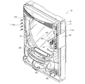
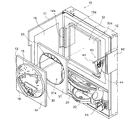
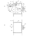
遊技機の概観について図1及び図2を用いて説明する。図1は、本実施形態におけるパチンコ遊技機10の概観を示す斜視図である。また、図2は、本実施形態におけるパチンコ遊技機10の概観を示す分解斜視図である。
Hereinafter, the gaming machine according to the present embodiment will be described more specifically with reference to the drawings. In the present embodiment, the gaming machine is described as a pachinko gaming machine.
[Composition of gaming machine]
An overview of the gaming machine will be described with reference to FIGS. FIG. 1 is a perspective view showing an overview of a pachinko gaming machine 10 according to the present embodiment. FIG. 2 is an exploded perspective view showing an overview of the pachinko gaming machine 10 according to the present embodiment.

図1及び図2に示すように、パチンコ遊技機10は、前面に開口12aが形成された本体枠12と、その本体枠12における開口12aの内部に配設される各種の部品と、本体枠12の前方に開閉自在に軸着された扉11とから構成されている。この扉11は、図1に示すように、開口12aを前面から閉鎖するためのものであり、通常閉鎖した状態で遊技が行われる。また、本体枠12の前面には、上皿20、下皿22、発射ハンドル26等が配設されている。   As shown in FIG. 1 and FIG. 2, the pachinko gaming machine 10 includes a main body frame 12 having an opening 12a formed on the front surface, various components disposed inside the opening 12a in the main body frame 12, and a main body frame. The door 11 is pivotally attached to the front of the door 12 so as to be openable and closable. As shown in FIG. 1, this door 11 is for closing the opening 12a from the front, and a game is normally performed in the closed state. Further, an upper plate 20, a lower plate 22, a firing handle 26, and the like are disposed on the front surface of the main body frame 12.

本体枠12の開口12a内部には、画像を表示する表示手段としての液晶表示装置32と、スペーサー31、遊技盤14等が配設されている。なお、遊技盤14、スペーサー31、液晶表示装置32以外の各種の部品(図示せず)については、理解を容易にするために説明を省略する。   Inside the opening 12a of the main body frame 12, a liquid crystal display device 32 as display means for displaying an image, a spacer 31, a game board 14 and the like are disposed. In addition, description is abbreviate | omitted in order to make an understanding easy about various components (not shown) other than the game board 14, the spacer 31, and the liquid crystal display device 32. FIG.

遊技盤14は、その全部が透過性を有する板形状の樹脂(透過性を有する部材)によって形成されている。この透過性を有する部材としては、例えば、アクリル樹脂、ポリカーボネート樹脂、メタクリル樹脂など各種の材質からなる。また、遊技盤14は、その前面側に、発射された遊技球が転動可能な遊技領域15を有している。この遊技領域15は、ガイドレール30に囲まれ、遊技球が転動可能な領域である。また、遊技盤14における遊技領域15には複数の障害釘13が打ちこまれている。   The game board 14 is entirely formed of a plate-shaped resin (a member having permeability) having permeability. Examples of the member having transparency include various materials such as acrylic resin, polycarbonate resin, and methacrylic resin. In addition, the game board 14 has a game area 15 on the front side thereof in which the launched game ball can roll. The game area 15 is an area surrounded by the guide rail 30 and allowing the game ball to roll. In addition, a plurality of obstacle nails 13 are driven into the game area 15 of the game board 14.

遊技に関する演出画像を表示する表示手段の一例である液晶表示装置32は、スペーサー31を挟んで、遊技盤14の背後に設けられている。すなわち、液晶表示装置32は、遊技盤14の透過性を有する部材の背後に配置されている。この液晶表示装置32は、遊技に関する画像の表示を可能とする表示領域32aを有している。この表示領域32aは、遊技盤14の全部又は一部に、スペーサー31を挟んで、背面側から重なるように配設される。具体的には、液晶表示装置32は、その表示領域32aが遊技領域15の全部又は一部と、遊技領域外域16の全部又は一部とに重なるように遊技盤14の後方に配設される。この液晶表示装置32における表示領域32aには、演出用の演出画像、装飾用の装飾画像等、各種の画像が表示される。   A liquid crystal display device 32, which is an example of display means for displaying an effect image related to a game, is provided behind the game board 14 with a spacer 31 interposed therebetween. In other words, the liquid crystal display device 32 is disposed behind the transparent member of the game board 14. The liquid crystal display device 32 has a display area 32a that enables display of an image relating to a game. The display area 32a is disposed so as to overlap the whole or a part of the game board 14 from the back side with the spacer 31 interposed therebetween. Specifically, the liquid crystal display device 32 is disposed behind the game board 14 so that the display area 32 a overlaps all or part of the game area 15 and all or part of the game area outer area 16. . In the liquid crystal display device 32, various images such as a production effect image and a decoration image are displayed in the display area 32a.

また、本実施形態において、遊技盤14における透過性領域の背後に液晶表示装置32などの表示手段を設けることにより、例えば、障害釘の植設領域や役物、装飾部材といった遊技部材を設ける領域を大きくし、レイアウトの自由度も更に大きくすることが可能である。   Further, in the present embodiment, by providing display means such as the liquid crystal display device 32 behind the transmissive region in the game board 14, for example, a region where game members such as an obstacle nail planting region, an accessory, and a decorative member are provided. And the degree of freedom in layout can be further increased.

スペーサー31は、遊技盤14の後方(背面側)に配設されるとともに、液晶表示装置32の前方(前面側)に配設される。つまり、スペーサー31は、遊技盤14と液晶表示装置32によって挟持される。このスペーサー31は、透過性を有した材料で形成されており、中央に大きな貫通穴31aが設けられている。貫通穴31aには、電飾ユニット53が設けられている。   The spacer 31 is disposed on the rear side (back side) of the game board 14 and on the front side (front side) of the liquid crystal display device 32. That is, the spacer 31 is sandwiched between the game board 14 and the liquid crystal display device 32. The spacer 31 is made of a permeable material, and has a large through hole 31a at the center. An electrical decoration unit 53 is provided in the through hole 31a.

図3を参照して、特別図柄表示器33、普通図柄表示器35、特別図柄保留ランプ34a〜34dおよび普通図柄保留ランプ50a〜50dを説明する。図3は、電飾ユニット53の拡大図である。   With reference to FIG. 3, the special symbol display 33, the normal symbol display 35, the special symbol hold lamps 34a to 34d, and the normal symbol hold lamps 50a to 50d will be described. FIG. 3 is an enlarged view of the electrical decoration unit 53.

図3に示すように、表示器ケース37に収容される特別図柄表示器33は、7セグメントLED41で構成されている。この7セグメントLED41は、所定の特別図柄の変動表示開始条件の成立により、点灯・消灯を繰り返す。7セグメントLED41の点灯・消灯によって、“0”から“9”までの10個の数字図柄が、特別図柄として変動表示される。
本実施形態においては、パチンコ遊技機10の遊技状態は、大別して一般遊技状態(大当たりの抽選を行いながら遊技球を消費する、所謂遊技客に不利な状態)と大当たり遊技状態(遊技客にとって短時間で大量の遊技球の獲得が期待できる、所謂遊技客にとって有利な状態)に分かれる。さらに、後述の特別図柄制御処理において抽選された、前記特別図柄表示器33に変動停止表示される特定の数字図柄により、15R確変大当り遊技状態、2R確変大当り遊技状態または15R通常大当り遊技状態の、3種類の大当たり遊技状態が決定する。そして、それぞれの大当たり遊技状態が終了後、前記一般遊技状態も、確変モードまたは時短モードと異なる状態の一般遊技状態へ移行する。
つまり、前記特別図柄として、特定の数字図柄(例えば、“7”の数字図柄)が停止表示された場合は、一般遊技状態から遊技者に有利なラウンドゲームを最大15回継続して行われる15R確変大当り遊技状態に移行する。また、特定の数字図柄(例えば、“3”の数字図柄)が停止表示された場合は、一般遊技状態から遊技者に有利なラウンドゲームを最大2回継続して行われる2R確変大当り遊技状態に移行する。そして、大当り遊技状態の終了後は、大当り遊技状態に移行する確率が通常より高い一般遊技状態である確変モードに移行する。特定の数字図柄(例えば、“5”の数字図柄)が停止表示された場合は、一般遊技状態から遊技者に有利なラウンドゲームを最大15回継続して行われる15R通常大当り遊技状態に移行する。そして、大当り遊技状態の終了後は、一般遊技状態である時短モードに移行する。この時短モードは、前記特別図柄の変動回数(例えば100回)を消化すると、一般遊技状態である通常モード(パチンコ遊技機10において最も基本的な一般遊技状態)に移行する。
As shown in FIG. 3, the special symbol display 33 accommodated in the display case 37 is composed of a 7-segment LED 41. The 7-segment LED 41 is repeatedly turned on and off when a predetermined special symbol variation display start condition is satisfied. By turning on / off the 7-segment LED 41, 10 numeric symbols from “0” to “9” are variably displayed as special symbols.
In the present embodiment, the gaming state of the pachinko gaming machine 10 is roughly classified into a general gaming state (consuming game balls while performing a jackpot lottery, a so-called disadvantageous state for the player) and a jackpot gaming state (short for the player). It is divided into a so-called advantageous state for a player who can expect to acquire a large amount of game balls in time. Further, according to a specific numerical symbol that is randomly selected and displayed in the special symbol display unit 33 in a special symbol control process described later, a 15R probability variable big hit gaming state, a 2R probability variable big hit gaming state, or a 15R normal big hit gaming state, Three types of jackpot gaming states are determined. And after each jackpot game state is complete | finished, the said general game state also transfers to the general game state of a state different from a probability change mode or a time-saving mode.
That is, when a specific numeric symbol (for example, a numeric symbol “7”) is stopped and displayed as the special symbol, a round game advantageous to the player from the general gaming state is continuously performed up to 15 times. Transition to a promising big hit gaming state. In addition, when a specific numeric symbol (for example, a numeric symbol of “3”) is stopped and displayed, the game state is changed from the general gaming state to the 2R probability variable big hit gaming state in which the round game advantageous to the player is continuously performed twice. Transition. Then, after the end of the big hit gaming state, the mode shifts to a probability change mode, which is a general gaming state in which the probability of changing to the big hit gaming state is higher than usual. When a specific numerical symbol (for example, a numerical symbol of “5”) is stopped and displayed, a transition is made from a general gaming state to a 15R normal jackpot gaming state in which a round game advantageous to the player is continuously performed up to 15 times. . Then, after the big hit gaming state ends, the mode shifts to the time saving mode which is the general gaming state. At this time, the short mode is shifted to the normal mode (the most basic general game state in the pachinko gaming machine 10), which is a general game state, when the number of changes (for example, 100 times) of the special symbol is digested.

一方、特別図柄として、特定の数字図柄以外の数字図柄(例えば、“3”、“5”、または“7”以外の数字図柄)が停止表示された場合は、基本的に一般遊技状態は移行しない。但し、詳細は後述の特別図柄制御処理で説明するが、一般遊技状態が時短モードの場合は、特別図柄の変動回数が所定の変動回数(例えば100回)に達したと判断すると、一般遊技状態を時短モードから通常モードへ移行する。以上のように、特別図柄が変動表示された後、停止表示され、その結果によって遊技状態が移行又は維持されるゲームを「特別図柄ゲーム」という。   On the other hand, if a number symbol other than a specific number symbol (for example, a number symbol other than “3”, “5”, or “7”) is stopped and displayed as a special symbol, the general gaming state basically shifts. do not do. However, the details will be described in the special symbol control process described later. When the general gaming state is the short-time mode, the general gaming state is determined when the number of variations of the special symbol has reached a predetermined variation number (for example, 100 times). Is switched from the short-time mode to the normal mode. As described above, a game in which a special symbol is variably displayed and then stopped and the game state is shifted or maintained according to the result is referred to as a “special symbol game”.

表示器ケース37の左右の両側には、特別図柄保留ランプ34a〜34dが設けられている。この特別図柄保留ランプ34a〜34dは、点灯又は消灯によって保留されている特別図柄の変動表示の実行回数(所謂、「特別図柄の保留球数」)を表示する。   On both the left and right sides of the display case 37, special symbol holding lamps 34a to 34d are provided. The special symbol hold lamps 34a to 34d display the number of executions of the special symbol variation display held by turning on or off (so-called “number of special symbols on hold ball”).

特別図柄表示器33の右側には、普通図柄表示器35が設けられている。普通図柄表示器35は、2つの表示用ランプ(図示せず)で構成されており、これら表示用ランプが交互に点灯・消灯を繰り返すことによって、例えば“○”、“×”等の記号が普通図柄として変動表示される。   A normal symbol display 35 is provided on the right side of the special symbol display 33. The normal symbol display 35 is composed of two display lamps (not shown). When these display lamps are alternately turned on and off, symbols such as “O” and “X” are displayed. Fluctuated display as a normal symbol.

表示器ケース37の下側には、普通図柄保留ランプ50a〜50dが設けられている。この普通図柄保留ランプ50a〜50dは、後述するように、点灯又は消灯によって保留されている普通図柄の変動表示の実行回数(所謂、「普通図柄の保留球数」)を表示する。   Under the display case 37, normal symbol holding lamps 50a to 50d are provided. As will be described later, the normal symbol holding lamps 50a to 50d display the number of executions of the fluctuation display of the normal symbol held by turning on or off (so-called “the number of holding balls of the normal symbol”).

図1及び図2を用いたパチンコ遊技機10の概観の説明を続ける。遊技盤14の透過性領域の外側には、発光表示手段としての装飾ランプ133a、133bが配設されており、遊技状態に合わせた所定の発光態様の表示を行う。   The description of the overview of the pachinko gaming machine 10 using FIG. 1 and FIG. 2 is continued. Decorative lamps 133a and 133b as light emitting display means are arranged outside the transmissive area of the game board 14, and display a predetermined light emission mode according to the gaming state.

扉11には、透過性を有する保護板19が配設されている。この保護板19は、扉11が閉鎖された状態で遊技盤14の前面に対面するように配設されている。   A protective plate 19 having transparency is disposed on the door 11. The protection plate 19 is disposed so as to face the front surface of the game board 14 with the door 11 closed.

発射ハンドル26は本体枠12に対して回動自在に設けられている。また、発射ハンドル26の裏側には、駆動装置である発射ソレノイド(図示せず)が設けられている。さらに、発射ハンドル26の周縁部には、タッチセンサ(図示せず)が設けられている。このタッチセンサが遊技者により触接されたときには、遊技者により発射ハンドル26が握持されたと検知される。発射ハンドル26が遊技者によって握持され、かつ、時計回り方向へ回動操作されたときには、その回動角度に応じて発射ソレノイドに電力が供給され、上皿20に貯留された遊技球が遊技盤14に順次発射され、遊技が進められる。   The firing handle 26 is provided so as to be rotatable with respect to the main body frame 12. A firing solenoid (not shown) as a driving device is provided on the back side of the firing handle 26. Further, a touch sensor (not shown) is provided on the peripheral edge of the firing handle 26. When the touch sensor is touched by the player, it is detected that the firing handle 26 is gripped by the player. When the firing handle 26 is gripped by the player and is rotated in the clockwise direction, power is supplied to the firing solenoid according to the rotational angle, and the game ball stored in the upper plate 20 is played. It is fired sequentially on the board 14 and the game proceeds.

また、遊技盤14の後方(背面側)に配設されている液晶表示装置32の表示領域32aでは、前述した特別図柄表示器33において表示される特別図柄と関連する演出画像が表示される。   In addition, in the display area 32a of the liquid crystal display device 32 disposed behind (on the back side of) the game board 14, an effect image related to the special symbol displayed on the special symbol display 33 described above is displayed.

例えば、特別図柄表示器33で表示される特別図柄の変動表示中においては、液晶表示装置32の表示領域32aにおいて、一列の図柄列に数字や記号等からなる装飾図柄(演出用の識別情報でもある。例えば、“0”から“9”までの数字)が変動表示される。また、特別図柄表示器33において変動表示されていた特別図柄が停止表示されるとともに、液晶表示装置32の表示領域32aでも演出用の装飾図柄が停止表示される。   For example, during the variable display of the special symbol displayed on the special symbol display device 33, in the display area 32a of the liquid crystal display device 32, a decorative symbol (even identification information for production) is formed of a single symbol row in a single symbol row. For example, “0” to “9” are displayed in a variable manner. In addition, the special symbol that has been variably displayed on the special symbol display 33 is stopped and displayed, and the decorative symbol for effect is also stopped and displayed on the display area 32 a of the liquid crystal display device 32.

また、特別図柄表示器33において特別図柄として特定の数字図柄が停止表示された場合には、大当りであることを遊技者に把握させる演出画像が液晶表示装置32の表示領域32aにおいて表示される。具体的には、特別図柄表示器33において特別図柄として特定の数字図柄が停止表示された場合には、液晶表示装置32の表示領域32aにおいて表示される演出用の装飾図柄の組合せが特定の表示態様(例えば、“1”から“9”のいずれかが全て揃った状態で停止表示される態様)となる。   Further, when a special numerical symbol is stopped and displayed as a special symbol on the special symbol display 33, an effect image for allowing the player to grasp that it is a big hit is displayed in the display area 32a of the liquid crystal display device 32. Specifically, when a specific numeric symbol is stopped and displayed as a special symbol on the special symbol display 33, a combination of effect decorative symbols displayed in the display area 32a of the liquid crystal display device 32 is a specific display. A mode (for example, a mode in which all of “1” to “9” are stopped and displayed in a state where all of them are aligned).

この演出用の装飾図柄の組合せとして、特定の“奇数”の数字図柄が全て揃った状態で停止表示された場合(例えば、“111”〜“999” の数字図柄)は、一般遊技状態から遊技者に有利なラウンドゲームを最大15回継続して行われる15R確変大当り遊技状態に移行する。この場合は、前記特別図柄表示器33に表示される特定図柄は“7”である。また、特定の数字図柄が連番で停止表示された場合(例えば、“1”“2”“3”の数字図柄)は、一般遊技状態から遊技者に有利なラウンドゲームを最大2回継続して行われる2R確変大当り遊技状態に移行する。この場合は、前記特別図柄表示器33に表示される特定図柄は“3”である。さらに、特定の“偶数”の数字図柄が全て揃った状態で停止表示された場合(例えば、“222”〜“888” の数字図柄)は、一般遊技状態から遊技者に有利なラウンドゲームを最大15回継続して行われる15R通常大当り遊技状態に移行する。この場合は、前記特別図柄表示器33に表示される特定図柄は“5”である。このように、前述した、特別図柄表示器33に停止表示される特定図柄に対応した装飾図柄の組み合わせが、液晶表示装置32の表示領域32aにおいて停止表示される。   As a combination of decorative symbols for performance, when a specific “odd” number symbols are all stopped and displayed (for example, “111” to “999” number symbols), the game is played from the general gaming state. The game proceeds to a 15R probability variation big hit gaming state in which a round game advantageous to the user is continuously performed up to 15 times. In this case, the specific symbol displayed on the special symbol display 33 is “7”. In addition, when a specific numeric symbol is stopped and displayed with a serial number (for example, a numeric symbol of “1”, “2”, “3”), the round game advantageous to the player is continued at most twice from the general gaming state. The 2R probability variation big hit gaming state is performed. In this case, the specific symbol displayed on the special symbol display 33 is “3”. Furthermore, when a specific “even” number symbols are all displayed in a stopped state (for example, “222” to “888” number symbols), the round game that is advantageous to the player from the general gaming state is maximized. Transition to the 15R normal jackpot gaming state, which is continuously performed 15 times. In this case, the specific symbol displayed on the special symbol display 33 is “5”. As described above, the combination of the decorative symbols corresponding to the specific symbols stopped and displayed on the special symbol display 33 is stopped and displayed in the display area 32 a of the liquid crystal display device 32.

このように、液晶表示装置32の表示領域32aにおいて表示される演出用の装飾図柄の組合せが特定の表示態様となった場合には、更に、「大当り!!」などの文字画像とともに、喜んでいるキャラクタ画像が液晶表示装置32の表示領域32aにおいて表示される。   In this way, when the combination of effect decoration symbols displayed in the display area 32a of the liquid crystal display device 32 is in a specific display mode, the character image such as “big hit! The character image is displayed in the display area 32 a of the liquid crystal display device 32.

なお、本発明における遊技は、始動口25に遊技球が入球したことを契機に、遊技者にとって有利な遊技へ移行するか否かの抽選が行われ、特別図柄表示器33において識別図柄の変動表示が行われ、液晶表示装置32において演出としての装飾図柄の変動表示、及びこれに伴う演出表示が行われる遊技である。そして、抽選結果が当選となり、特別図柄表示器33及び液晶表示装置32において変動表示される特別図柄及び装飾図柄が、特定の表示態様となった場合(例えば、大当たりを示す表示態様)は、後述する演出制御手段によって、可動体80(図1、図2、図5(a)参照)、96(図6参照)が遊技機本体の外方に突出して所定の動作態様に応じた演出を行う。なお、この可動体80、96を用いた演出表示については後に詳述する。   In the game according to the present invention, when a game ball enters the start opening 25, a lottery is performed as to whether or not to shift to a game advantageous to the player, and the special symbol display 33 displays the identification symbol. This is a game in which a variable display is performed, and a decorative display variable display as an effect on the liquid crystal display device 32 and an accompanying effect display are performed. When the lottery result is selected and the special symbol and the decorative symbol variably displayed on the special symbol display device 33 and the liquid crystal display device 32 are in a specific display mode (for example, a display mode indicating a jackpot), a description will be given later. The movable body 80 (see FIG. 1, FIG. 2, FIG. 5 (a)), 96 (see FIG. 6) projects outward from the gaming machine main body and produces an effect according to a predetermined operation mode. . The effect display using the movable bodies 80 and 96 will be described in detail later.

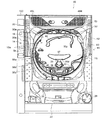
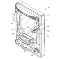
次に、図4を用いて、パチンコ遊技機10の概観を詳細に説明する。図4は、本実施形態におけるパチンコ遊技機10の概観を示す正面図である。なお、図4を用いたパチンコ遊技機10の概観の説明では、図1及び図2を用いたパチンコ遊技機10の概観の説明と重複する部分を省略する。また、図4においては、遊技盤14に打ち込まれている複数の障害釘13の記載を省略している。   Next, an overview of the pachinko gaming machine 10 will be described in detail with reference to FIG. FIG. 4 is a front view showing an overview of the pachinko gaming machine 10 in the present embodiment. Note that in the description of the overview of the pachinko gaming machine 10 using FIG. 4, portions that overlap with the description of the overview of the pachinko gaming machine 10 using FIGS. 1 and 2 are omitted. In FIG. 4, the description of the plurality of obstacle nails 13 driven into the game board 14 is omitted.

図4に示すように、遊技盤14には、2つのガイドレール30(30a及び30b)、障害物55、57、通過ゲート54、始動口25、大入賞口39、が設けられている。なお、遊技盤14の上部では、特別図柄表示器33、普通図柄表示器35等の電飾ユニット53(図3参照)が視認可能となっている。   As shown in FIG. 4, the game board 14 is provided with two guide rails 30 (30 a and 30 b), obstacles 55 and 57, a passage gate 54, a start opening 25, and a special winning opening 39. In addition, in the upper part of the game board 14, the electrical decoration units 53 (see FIG. 3) such as the special symbol display 33 and the normal symbol display 35 are visible.

遊技盤14の上部には障害物55が設けられ、遊技盤14の略中央には障害物57が設けられている。この障害物57下部には、始動口25が設けられている。   An obstacle 55 is provided in the upper part of the game board 14, and an obstacle 57 is provided in the approximate center of the game board 14. A starting port 25 is provided below the obstacle 57.

遊技盤14の左側に設けられている2つのガイドレール30は、遊技領域15を区画(画定)する外レール30aと、その外レール30aの内側に配設された内レール30bとから構成される。発射された遊技球は、遊技盤14上に設けられたガイドレール30に案内されて、遊技盤14の上部に移動し、電飾ユニット53上を通過して、前述した複数の障害釘13(図2参照)、遊技盤14上に設けられた障害物55、57等との衝突により、その進行方向を変えながら遊技盤14の下方に向かって流下する。   The two guide rails 30 provided on the left side of the game board 14 are composed of an outer rail 30a that partitions (defines) the game area 15 and an inner rail 30b that is disposed inside the outer rail 30a. . The launched game ball is guided by a guide rail 30 provided on the game board 14, moves to the upper part of the game board 14, passes through the electric decoration unit 53, and the plurality of obstacle nails 13 ( 2), due to the collision with the obstacles 55, 57, etc. provided on the game board 14, it flows down toward the lower side of the game board 14 while changing its traveling direction.

前述した始動口25に遊技球が入賞した場合(所定の特別図柄の変動表示開始の一つである。)には、特別図柄表示器33による特別図柄の変動表示が開始される。また、特別図柄の変動表示中に遊技球が始動口25へ入賞した場合には、変動表示中の特別図柄が停止表示されるまで、始動口25への遊技球の入賞に基づく特別図柄の変動表示の実行(開始)が保留される。その後、変動表示していた特別図柄が停止表示された後に、保留されていた特別図柄の変動表示が開始される。つまり、前記電飾ユニット53に設けられた、特別図柄保留ランプ34a〜34d(図3参照)は、保留された特別図柄の変動表示の実行回数に対応して、左から順番に点灯され、特別図柄の変動表示が一旦停止表示され、次の保留されていた特別図柄の変動表示が開始されると、それに対応した特別図柄保留ランプは消灯される。なお、特別図柄の変動表示の実行が保留される回数には上限が設定されており、例えば、4回(個)を上限として特別図柄の変動表示は保留される。   When a game ball wins at the start opening 25 described above (which is one of the start of the predetermined special symbol variation display), the special symbol display by the special symbol display 33 is started. Further, when the game ball wins the start opening 25 during the special symbol variation display, the special symbol variation based on the game ball winning at the start opening 25 is stopped until the special symbol being displayed is stopped. Display execution (start) is put on hold. Thereafter, after the special symbol that has been variably displayed is stopped and displayed, the variable symbol of the reserved special symbol is displayed. That is, the special symbol hold lamps 34a to 34d (see FIG. 3) provided in the lighting unit 53 are lit in order from the left in accordance with the number of executions of the variable display of the reserved special symbols. When the change display of the symbol is temporarily stopped and the next change display of the special symbol that has been put on hold is started, the special symbol hold lamp corresponding thereto is turned off. An upper limit is set for the number of times the execution of the special symbol variable display is suspended. For example, the special symbol variable display is suspended up to four times (number).

また、液晶表示装置32の表示領域32aにおいても、前述した始動口25に遊技球が入賞した場合には、前記特別図柄の変動表示の開始にあわせて、演出用の装飾図柄の変動表示が開始される。また、特別図柄に関する変動表示中に遊技球が始動口25へ入賞した場合には、変動表示中の演出用の識別情報が停止表示されるまで、始動口25への遊技球の入賞に基づく演出用の装飾図柄の変動表示の実行(開始)が保留される。その後、変動表示していた演出用の装飾図柄が停止表示された場合には、保留されていた演出用の装飾図柄の変動表示が開始される。   Also, in the display area 32a of the liquid crystal display device 32, when a game ball wins the start opening 25 described above, the variation display of the decorative design for production starts in accordance with the start of the variation display of the special symbol. Is done. Further, when the game ball wins the start opening 25 during the variation display regarding the special symbol, the effect based on the winning of the game ball at the start opening 25 until the identification information for the effect during the variation display is stopped and displayed. Execution (start) of the variable display of decorative symbols for use is suspended. Thereafter, when the decorative design for effect that has been variably displayed is stopped and displayed, the variable display of the decorative symbol for effect that has been put on hold is started.

なお、本実施形態においては、始動口25に遊技球が入賞したこと等を、所定の特別図柄の変動表示開始条件又は所定の演出用の装飾図柄の変動表示開始条件としたが、これに限らず、別の態様であってもよい。   In the present embodiment, the winning of a game ball at the start opening 25 is set as a predetermined special symbol variable display start condition or a predetermined decorative symbol variable display start condition. Alternatively, another embodiment may be used.

遊技盤14の略中央の左側には通過ゲート54が設けられている。この通過ゲート54には、後述する通過球センサ114(図8参照)が設けられている。通過球センサ114は、遊技球が通過ゲート54を通過したことを検出する。そして、通過球センサ114によって遊技球の通過が検出されたときには、普通図柄表示器35において普通図柄の変動表示が開始され、所定の時間が経過した後、普通図柄の変動表示が停止する。前述したように、この普通図柄は、“○”、“×”等の記号である。   A passing gate 54 is provided on the left side of the approximate center of the game board 14. The passing gate 54 is provided with a passing ball sensor 114 (see FIG. 8) described later. The passing ball sensor 114 detects that the game ball has passed through the passing gate 54. When the passing of the game ball is detected by the passing ball sensor 114, the normal symbol variation display is started on the normal symbol display 35, and after a predetermined time has elapsed, the normal symbol variation display is stopped. As described above, this normal symbol is a symbol such as “◯” or “x”.

この普通図柄が所定の図柄、例えば“○”として停止表示されたときには、始動口25の左右の両側に設けられている羽根部材(所謂、普通電動役物)23が閉鎖状態から開放状態となり、始動口25に遊技球が入りやすくなる。また、羽根部材23を開放状態とした後、所定の時間が経過したときには、羽根部材23を閉鎖状態として、始動口25に遊技球が入りにくくなるようにする。以上のように、普通図柄が変動表示された後、停止表示され、その結果によって羽根部材23の開放・閉鎖状態が異なってくるゲームを「普通図柄ゲーム」という。   When the normal symbol is stopped and displayed as a predetermined symbol, for example, “◯”, the blade members (so-called normal electric accessories) 23 provided on both the left and right sides of the start port 25 are changed from the closed state to the open state, It becomes easy for a game ball to enter the start opening 25. Further, when a predetermined time has elapsed after the blade member 23 is opened, the blade member 23 is closed to make it difficult for a game ball to enter the start port 25. As described above, a game in which the normal symbol is displayed in a variable manner and then stopped and the open / closed state of the blade member 23 differs depending on the result is referred to as a “normal symbol game”.

また、特別図柄の変動表示と同じように、普通図柄の変動表示中において通過ゲート54を遊技球が通過した場合には、変動表示中の普通図柄が停止表示されるまで、通過ゲート54への遊技球の通過に基づく普通図柄の変動表示の実行(開始)が保留される。つまり、前記電飾ユニット53に設けられた、普通図柄保留ランプ50a〜50d(図3参照)は、保留された普通図柄の変動表示の実行回数に対応して、左から順番に点灯され、変動が停止表示されると、次の保留されていた普通図柄の変動表示が開始され、それに対応した普通図柄保留ランプは消灯される。なお、普通図柄の変動表示の実行が保留される回数には上限が設定されており、例えば、4回(個)を上限として保留される。   As with the special symbol variation display, when the game ball passes through the passing gate 54 during the normal symbol variation display, until the normal symbol in the variation display is stopped and displayed, Execution (start) of normal symbol variation display based on the passing of the game ball is suspended. That is, the normal symbol hold lamps 50a to 50d (see FIG. 3) provided in the lighting unit 53 are lit in order from the left in accordance with the number of executions of the variable display of the held normal symbols. Is stopped, the next normal symbol variation display that has been put on hold is started, and the corresponding normal symbol hold lamp is turned off. Note that an upper limit is set for the number of times that the execution of the variable symbol display is suspended. For example, the upper limit is four times (pieces).

大入賞口39には、その前面側(前方)に開閉自在なシャッタ40が設けられている。このシャッタ40は、特別図柄表示器33において特別図柄として特定の数字図柄が停止表示され、遊技状態が前記の大当り遊技状態(つまり、15R確変大当たり、2R確変大当たりおよび15R通常大当たり状態)に移行された場合は、遊技球を受け入れやすい開放状態となるように駆動される。その結果、大入賞口39は、遊技球を受け入れやすい開放状態となる。   The big prize opening 39 is provided with a shutter 40 that can be opened and closed on the front side (front side). In the shutter 40, a special numerical symbol is stopped and displayed as a special symbol on the special symbol display 33, and the gaming state is shifted to the jackpot gaming state (that is, the 15R probability variation big hit, 2R probability variation big hit and 15R normal big hit state). If it is, it is driven so as to be in an open state where it is easy to accept the game ball. As a result, the special winning opening 39 is in an open state where it is easy to accept a game ball.

一方、シャッタ40の背面側(後方)に設けられた大入賞口39には、V・カウントセンサ102(図8参照)を有する特定領域(図示せず)と、カウントセンサ104(図8参照)を有する一般領域(図示せず)とがあり、それらの領域を遊技球が所定個数(例えば10個)通過するか、又は、所定時間(例えば30秒)が経過するまでシャッタ40が開放状態に駆動される。そして、開放状態において大入賞口39への所定数の遊技球の入賞又は所定時間の経過のいずれかの条件が成立すると、シャッタ40は、遊技球を受け入れ難い閉鎖状態になるように駆動される。その結果、大入賞口39は、遊技球を受け入れ難い閉鎖状態となる。   On the other hand, a special winning opening 39 provided on the back side (rear) of the shutter 40 includes a specific area (not shown) having a V / count sensor 102 (see FIG. 8) and a count sensor 104 (see FIG. 8). There are general areas (not shown) having a predetermined number (for example, 10) of game balls, or the shutter 40 is opened until a predetermined time (for example, 30 seconds) elapses. Driven. When a condition for winning a predetermined number of game balls in the grand prize opening 39 or elapse of a predetermined time is satisfied in the open state, the shutter 40 is driven so as to be in a closed state in which it is difficult to accept the game balls. . As a result, the special winning opening 39 is in a closed state in which it is difficult to accept a game ball.

なお、大入賞口39が遊技球を受け入れやすい状態となっている開放状態から大入賞口39が遊技球を受け入れ難い状態となっている閉鎖状態までの遊技をラウンドゲームという。したがって、シャッタ40は、ラウンドゲーム時に開放し、各ラウンドゲーム間では閉鎖することになる。また、ラウンドゲームは、“1”ラウンド、“2”ラウンド等のラウンド数として計数される。例えば、ラウンドゲームの1回目を第1ラウンド、2回目を第2ラウンドと呼称する場合がある。   A game from an open state in which the big prize opening 39 is in a state in which it is easy to accept game balls to a closed state in which the big prize opening 39 is in a state in which it is difficult to accept game balls is called a round game. Therefore, the shutter 40 is opened during the round game and is closed between the round games. A round game is counted as the number of rounds, such as “1” round and “2” round. For example, the first round game may be referred to as the first round and the second round as the second round.

続いて、開放状態から閉鎖状態に駆動されたシャッタ40は、開放状態において大入賞口39に受け入れられた遊技球がV・カウントセンサ102を通過したことを条件に、再度開放状態に駆動される。つまり、シャッタ40の開放状態において大入賞口39に受け入れられた遊技球がV・カウントセンサ102を通過したことを条件に、次のラウンドゲームへ継続して進むことができる。なお、第1ラウンドのラウンドゲームから、次のラウンドゲームに継続して進むことができない(最終の)ラウンドゲームが終了するまでの遊技を大当り遊技状態という。すなわち、大当り遊技状態は遊技者にとって有利な遊技状態である。   Subsequently, the shutter 40 driven from the open state to the closed state is driven to the open state again on condition that the game ball received in the big prize opening 39 in the open state has passed through the V / count sensor 102. . In other words, it is possible to continue to the next round game on condition that the game ball received in the special winning opening 39 in the opened state of the shutter 40 has passed the V · count sensor 102. Note that the game from the first round game until the end of the (final) round game that cannot continue to the next round game is called a big hit game state. That is, the big hit gaming state is a gaming state advantageous to the player.

また、本実施形態においては、役物の一例として、大入賞口39の役物が記載されているが、本発明はこれに限定されず、遊技盤上に2つ以上のいかなる数の役物が設けられてもよい。   Further, in the present embodiment, as an example of an accessory, an accessory of the big prize opening 39 is described, but the present invention is not limited to this, and any number of two or more accessories on the game board. May be provided.

本実施形態では、大当たり遊技状態の実行中において、最初のラウンド数から最もラウンドゲームが継続された場合の最後のラウンドゲームまでのラウンド数(最大継続ラウンド数)は、15ラウンドまたは2ラウンドである。なお、大当たり遊技状態の実行中における最大継続ラウンド数は限定されるものではない。例えば、最大継続ラウンド数は、ラウンド数抽選手段(後述するメインCPU66を含む主制御回路60(図8参照))による抽選により、“1”ラウンドから“15”ラウンドまでの間から選択されるなど、任意のラウンド数であってもよい。   In the present embodiment, during execution of the jackpot gaming state, the number of rounds from the first round number to the last round game when the round game is continued (maximum duration round number) is 15 rounds or 2 rounds. . Note that the maximum number of consecutive rounds during execution of the jackpot gaming state is not limited. For example, the maximum continuation round number is selected from “1” to “15” rounds by lottery by a round number lottery means (a main control circuit 60 including a main CPU 66 described later (see FIG. 8)). Any number of rounds may be used.

また、前述した始動口25、一般入賞口56a〜56d、大入賞口39における特定領域及び一般領域に遊技球が入賞又は通過したときには、それぞれの入賞口の種類に応じて予め設定されている数の遊技球が上皿20又は下皿22に払い出される。   In addition, when a game ball wins or passes through the specific area and the general area in the start opening 25, the general winning openings 56a to 56d, and the large winning opening 39, the number set in advance according to the type of each winning opening. The game balls are paid out to the upper plate 20 or the lower plate 22.

なお、本実施形態において、画像を表示する部分として液晶ディスプレイパネルからなる液晶表示装置32を採用したが、これに限らず、他の態様であってもよく、例えば、CRT(Cathode Ray Tube)を含むブラウン管、ドットLED、セグメントLED、EL(Electronic Luminescent)、プラズマ等からなるものであってもよい。また、本実施形態においては、液晶表示装置32は、遊技機であるパチンコ遊技機10における遊技盤14の正面略中央に設けられている場合を示したが、遊技者により視認可能な位置であれば何処の位置に液晶表示装置32を設けることとしてもよい。また、本実施形態においては、液晶表示装置32とは別に特別図柄表示器33および普通図柄表示器35を備えるように構成したが、これに限らず、液晶表示装置32に特別図柄及び普通図柄を変動表示させるように構成してもよい。また、変動表示手段として液晶表示装置32を採用したが、これに限らず、別の態様であってもよく、例えば、ドラム、ベルト、リーフ等を変動表示手段として採用してもよい。   In the present embodiment, the liquid crystal display device 32 including a liquid crystal display panel is used as a portion for displaying an image. However, the present invention is not limited to this, and other modes may be used. For example, a CRT (Cathode Ray Tube) is used. It may be composed of a cathode ray tube, a dot LED, a segment LED, an EL (Electronic Luminescent), plasma, or the like. Further, in the present embodiment, the liquid crystal display device 32 is shown in the case where it is provided in the approximate center of the front of the game board 14 in the pachinko gaming machine 10 that is a gaming machine, but it may be a position that can be visually recognized by the player. For example, the liquid crystal display device 32 may be provided at any position. In the present embodiment, the special symbol display 33 and the normal symbol display 35 are provided separately from the liquid crystal display device 32. However, the present invention is not limited thereto, and the liquid crystal display device 32 is provided with the special symbol and the normal symbol. You may comprise so that a fluctuation | variation display may be carried out. Further, the liquid crystal display device 32 is adopted as the fluctuation display means, but the present invention is not limited to this, and other modes may be adopted. For example, a drum, a belt, a leaf, or the like may be adopted as the fluctuation display means.

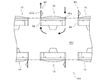
上記した構成を有するパチンコ遊技機10において、本実施形態に係るパチンコ遊技機10は、上記した液晶表示装置32による演出効果に加えて、遊技機本体を構成する遊技盤14より外方(本実施形態では前方)に突出して所定の動作態様により演出効果を奏することができる可動体80と、この可動体80に風を吹きつけることによって可動態様に変化させることができる送風手段81を具備することを特徴としている。以下、可動体80及び送風手段81の構成を図1、図2及び図5(a)、(b)を参照して説明する。   In the pachinko gaming machine 10 having the above-described configuration, the pachinko gaming machine 10 according to the present embodiment is outside of the gaming board 14 that constitutes the gaming machine main body in addition to the effect of the liquid crystal display device 32 described above (this embodiment). A movable body 80 projecting forward (in the form) and capable of producing an effect by a predetermined operation mode; and a blowing means 81 that can be changed to a movable mode by blowing wind on the movable body 80. It is characterized by. Hereinafter, the structure of the movable body 80 and the blowing means 81 will be described with reference to FIGS. 1, 2, 5 (a), and (b).

図示するように、可動体80は、本体枠12の一側壁に設けた前面開口の矩形箱体からなるケーシング82内に外方(本実施形態では前方)に向けて出没自在に配置されている棒状の可動体本体83と、基部を可動体本体83に固着すると共に先端を自由端とした柔軟素材である布等からなる三角形状の旗84とから構成されている。   As shown in the figure, the movable body 80 is disposed in a casing 82 formed of a rectangular box with a front opening provided on one side wall of the main body frame 12 so as to be able to protrude and retract outward (in the present embodiment, forward). It is composed of a rod-shaped movable body main body 83 and a triangular flag 84 made of a cloth or the like which is a flexible material having a base fixed to the movable body main body 83 and having a free end at the tip.

このような可動体80の出没動作を行うための駆動手段としては、各種形態の手段が考えられるが、本実施形態では、図5(a)に示す水平突出状態において、棒状の可動体本体83の基端上部を枢軸85によって回転自在に枢支し、かつ基端の周囲に固着したセクターワームホイール86に、回動モータ87によって駆動されるワームギア88を噛合させる構成としている。   Various types of means are conceivable as the driving means for performing the moving operation of the movable body 80. In the present embodiment, the rod-shaped movable body main body 83 in the horizontally projecting state shown in FIG. A worm gear 88 driven by a rotation motor 87 is meshed with a sector worm wheel 86 that is pivotally supported by a pivot 85 and fixed around the base end.

かかる構成によって、後述する可動体制御手段からの制御信号に基づいて回動モータ87を駆動することによって、常時は、図5(a)に点線で示すようにケーシング82内に収納状態にある可動体80を、実線で示す水平位置まで外方(本実施形態では前方)に回転しながら突出させることができる。また、回動モータ87を逆転させることによって、可動体80をケーシング82内に回転しながら収納することができる。   With this configuration, the rotating motor 87 is driven on the basis of a control signal from a movable body control means, which will be described later, so that the movable state is normally stored in the casing 82 as indicated by the dotted line in FIG. The body 80 can be protruded while rotating outward (forward in this embodiment) to a horizontal position indicated by a solid line. Further, the movable body 80 can be stored in the casing 82 while being rotated by reversing the rotation motor 87.

また、本実施形態では、ケーシング82の後部壁89に設けた吸気口90に送風手段81が取り付けられている。具体的には、送風手段81は、後部壁89に、後面に開口91aを形成した取付フレーム91を突設し、この取付フレーム91に吸気口90と対向させた送風ファン92と、送風ファン92を回転駆動する回動モータ93とを設けて構成している。   In the present embodiment, the air blowing means 81 is attached to the air inlet 90 provided in the rear wall 89 of the casing 82. Specifically, the blowing means 81 has a rear wall 89 provided with a mounting frame 91 having an opening 91a formed on the rear surface thereof, and a blower fan 92 that faces the intake port 90 on the mounting frame 91, and a blower fan 92. And a rotation motor 93 that rotationally drives the motor.

かかる構成によって、後述する可動体制御手段からの制御信号に基づいて回動モータ93を駆動することによって、ケーシング82を通して、可動体80、特に布等からなる三角形状の旗84に向けて風を送ることができ、旗84をはためかせることができる。   With this configuration, the rotation motor 93 is driven on the basis of a control signal from the movable body control means, which will be described later, so that the wind is passed through the casing 82 toward the movable body 80, particularly the triangular flag 84 made of cloth or the like. Can be sent and the flag 84 flipped.

このように、可動体80をケーシング82から遊技機本体の外方(本実施形態では前方)に突出させ、かつ、旗84に向けて風を送ることによってはためかせることによって、可動体80の動作態様を変化させることができ、これまでにない大きなインパクトのある斬新な演出をなすことができ、遊技者の遊技に対する興趣を著しく高めることができる。   As described above, the movable body 80 is projected from the casing 82 to the outside of the gaming machine main body (forward in the present embodiment) and fluttered by sending wind toward the flag 84. It is possible to change the operation mode, to make a novel production with an unprecedented great impact, and to significantly enhance the interest of the player in the game.

また、本実施形態では、図5(a)に示すように、ケーシング82内であって、送風手段81の前方をなす位置に、回動モータ94によって所定角度で揺動自在な偏向板95が配設されている。   Further, in the present embodiment, as shown in FIG. 5A, a deflection plate 95 that can be swung at a predetermined angle by a rotation motor 94 is provided in the casing 82 and in front of the air blowing means 81. It is arranged.

かかる構成によって、可動体80の旗8に吹き付ける風の角度を自在に変化させることができ、簡単な構成で演出の多様性を実現することができる。また、演出の多様性は、送風ファン92を回転駆動する回動モータ93の回転数を変えることによって吹きつけ強度を変えることによっても実現できる。   With this configuration, the angle of the wind blown on the flag 8 of the movable body 80 can be freely changed, and a variety of effects can be realized with a simple configuration. The variety of effects can also be realized by changing the blowing strength by changing the rotation speed of the rotation motor 93 that rotationally drives the blower fan 92.

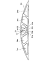
また、可動体80の構成は、図1、図2及び図5(a)に示す形態に何ら限定されるものではなく、例えば、図6に示す構成とすることもできる。   Moreover, the structure of the movable body 80 is not limited to the form shown in FIG.1, FIG.2 and FIG.5 (a) at all, For example, it can also be set as the structure shown in FIG.

即ち、図6に示す可動体96は、図示しない進退シリンダを用いて吹流し状の可動体本体97をケーシング98に設けた縦長スリット98aから外方に出没させる構成としている。また、ケーシング98の後部には、図1、図2及び図5(a)に示す可動体80の場合と同様に、図示しない送風手段が取り付けられており、ケーシング98を通して可動体本体97に風を吹きつけることができる。   That is, the movable body 96 shown in FIG. 6 has a configuration in which a wind-movable movable body main body 97 is projected and retracted outward from a vertically long slit 98 a provided in the casing 98 by using an advancing and retreating cylinder (not shown). Further, as in the case of the movable body 80 shown in FIGS. 1, 2, and 5 (a), air blowing means (not shown) is attached to the rear portion of the casing 98, and the wind is applied to the movable body main body 97 through the casing 98. Can be sprayed.

ここで、吹流し状の可動体本体97は、常態では縦長スリット98aを通過可能な縦長扁平断面を有し、かつ、前端に小孔99を設けると共に後端を全面開口した弾性を有する扁平筒体からなる。かかる構成によって、可動体本体97は、待機時はケーシング98内に扁平形状を保持しながら収納され、その後、縦長スリット98aを通して、ケーシング98から外方に突出し、その後、送風手段からの風を受けることによって膨らみ、可動体80の旗84と同様にはためくことになる。   Here, the streamer-shaped movable body main body 97 has a vertically long flat cross section that can normally pass through the vertically long slit 98a, has a small hole 99 at the front end, and has elasticity that has the rear end opened entirely. Consists of. With this configuration, the movable body main body 97 is stored in the casing 98 while maintaining a flat shape during standby, and then protrudes outward from the casing 98 through the longitudinal slit 98a, and then receives wind from the blowing means. It is swollen by this and flutters in the same manner as the flag 84 of the movable body 80.

このように、可動体96をケーシング98から遊技機本体の外方(本実施形態では前方)に突出させ、かつ、可動体本体97に向けて風を送ることによってはためかせることによって、可動体96の動作態様を変化させることができ、これまでにない大きなインパクトのある斬新な演出をなすことができ、遊技者の遊技に対する興趣を著しく高めることができる。   In this way, the movable body 96 is projected from the casing 98 to the outside of the gaming machine main body (in the present embodiment, forward) and fluttered by sending wind toward the movable body main body 97, thereby moving the movable body. 96 operation modes can be changed, an unprecedented large-scale impact production can be made, and the player's interest in games can be significantly enhanced.

さらに、本実施形態では、図7に示すように、遊技設備である遊技島100は、上述してきたパチンコ遊技機10における遊技機本体の幅方向に複数台並設してなる設備本体を、各遊技機本体の後方側が所定空間を介して向かい合うように2列配置した構成としており、かかる遊技島100において、各パチンコ遊技機10に設けられた送風手段は、各遊技機本体の後方側における遊技島100の内部空間101内の空気を、各遊技機本体の前方側に突出された可動体80に向けて吹き付けるようにしている。なお、風の吹出口は、可動体80を出没させる開口と兼用可能であり、また、本実施形態では、図1、図2、図5(b)及び図6に示すように、外部空気を内部空間101内に吸引する吸気口12bを具備するケーシング103を、各パチンコ遊技機10のケーシング82、98と反対側に設けている。なお、図5(b)に示すように、ケーシング103の後部には、外部空気の内部空間101内への吸引を促進するため、送風手段81aが配設されている。   Furthermore, in this embodiment, as shown in FIG. 7, the gaming island 100, which is a gaming facility, includes a plurality of equipment main bodies arranged in parallel in the width direction of the gaming machine main body in the pachinko gaming machine 10 described above. Two rows are arranged so that the rear side of the gaming machine main body faces each other through a predetermined space. In such a gaming island 100, the blowing means provided in each pachinko gaming machine 10 is a game on the rear side of each gaming machine main body. The air in the internal space 101 of the island 100 is blown toward the movable body 80 projecting to the front side of each gaming machine main body. Note that the wind outlet can also be used as an opening through which the movable body 80 appears and exits. In the present embodiment, as shown in FIGS. 1, 2, 5B, and 6, external air can be used. A casing 103 having an air inlet 12b for sucking into the internal space 101 is provided on the opposite side of the casings 82 and 98 of each pachinko gaming machine 10. As shown in FIG. 5B, a blower 81a is disposed at the rear portion of the casing 103 in order to promote the suction of the external air into the internal space 101.

かかる構成によって、高温になりがちな内部空間101内の空気を可動体80、96に吹き付けることで、外部と内部空間101との間で換気させるようにして、内部空間101の温度上昇を可及的に防止し、パチンコ遊技機10の後述する主制御回路60や副制御回路200の温度上昇による誤作動や故障を未然に防止することができる。
[遊技機の電気的構成]
本実施形態におけるパチンコ遊技機10の制御回路について図8を用いて説明する。図8は、本実施形態におけるパチンコ遊技機10の制御回路を示すブロック図である。
With such a configuration, the temperature of the internal space 101 can be increased by blowing the air in the internal space 101, which tends to be high temperature, to the movable bodies 80 and 96 so as to ventilate between the external space and the internal space 101. Therefore, it is possible to prevent malfunction and failure due to a temperature rise in a later-described main control circuit 60 and sub-control circuit 200 of the pachinko gaming machine 10.
[Electric configuration of gaming machine]
A control circuit of the pachinko gaming machine 10 in this embodiment will be described with reference to FIG. FIG. 8 is a block diagram showing a control circuit of the pachinko gaming machine 10 in the present embodiment.

本実施形態におけるパチンコ遊技機10の制御回路は、主に、遊技制御手段としての主制御回路60と、演出制御手段としての副制御回路200とから構成される。主制御回路60は、遊技の制御を行うものであり、副制御回路200は、遊技の進行に応じた演出の制御(例えば、可動体の駆動制御、画像表示制御、音声出音制御、装飾ランプ制御等)を行うものである。   The control circuit of the pachinko gaming machine 10 in the present embodiment is mainly composed of a main control circuit 60 as game control means and a sub-control circuit 200 as effect control means. The main control circuit 60 controls the game, and the sub control circuit 200 controls the production according to the progress of the game (for example, drive control of the movable body, image display control, sound output control, decoration lamp) Control, etc.).

主制御回路60は、図8に示すように、制御手段であるメインCPU66、メインROM(読み出し専用メモリ)68、メインRAM(読み書き可能メモリ)70を備えている。この主制御回路60は、遊技の進行を制御する。   As shown in FIG. 8, the main control circuit 60 includes a main CPU 66, a main ROM (read only memory) 68, and a main RAM (read / write memory) 70 as control means. The main control circuit 60 controls the progress of the game.

メインCPU66には、メインROM68、メインRAM70等が接続されており、このメインROM68に記憶されたプログラムに従って、各種の処理を実行する機能を有する。このように、このメインCPU66は、例えば、特別遊技実行手段や抽選手段として機能するなど、後述する各種の手段として機能することとなる。   The main CPU 66 is connected to a main ROM 68, a main RAM 70, and the like, and has a function of executing various processes according to a program stored in the main ROM 68. Thus, the main CPU 66 functions as various means to be described later, such as functioning as a special game execution means or a lottery means.

メインROM68には、メインCPU66によりパチンコ遊技機10の動作を制御するためのプログラムが記憶されており、その他には、乱数抽選によって大当り判定をする際に参照される大当り判定テーブル(図9の(a)参照)や、演出を選択する際に参照される可動体大当たり演出判定テーブル(図9の(b)参照)、または、可動体遊技状態演出判定テーブル(図9の(c)参照)等の各種のテーブルが記憶されている。   In the main ROM 68, a program for controlling the operation of the pachinko gaming machine 10 by the main CPU 66 is stored. In addition, a big hit determination table (refer to FIG. a)), a movable body big hit effect determination table (see (b) of FIG. 9) referred to when selecting an effect, or a movable body game state effect determination table (see (c) of FIG. 9), etc. The various tables are stored.

メインRAM70は、メインCPU66の一時記憶領域として種々のフラグや変数の値を記憶する機能を有する。   The main RAM 70 has a function of storing various flags and variable values as a temporary storage area of the main CPU 66.

また、この主制御回路60は、所定の周波数のクロックパルスを生成するリセット用クロックパルス発生回路62、電源投入時においてリセット信号を生成する初期リセット回路64、後述する副制御回路200に対してコマンドを供給するためのシリアル通信用IC72を備えている。また、これらのリセット用クロックパルス発生回路62、初期リセット回路64、シリアル通信用IC72は、メインCPU66に接続されている。なお、このリセット用クロックパルス発生回路62は、後述するシステムタイマ割込処理を実行するために、所定の周期(例えば2ミリ秒)毎にクロックパルスを発生する。尚、このシリアル通信用IC72は、各種のコマンドを副制御回路200(副制御回路200に含まれる各種の手段)へ送信する送信手段に相当する。   The main control circuit 60 also has a command for a reset clock pulse generating circuit 62 that generates a clock pulse of a predetermined frequency, an initial reset circuit 64 that generates a reset signal when the power is turned on, and a sub-control circuit 200 described later. IC for serial communication 72 is provided. The reset clock pulse generation circuit 62, the initial reset circuit 64, and the serial communication IC 72 are connected to the main CPU 66. The reset clock pulse generation circuit 62 generates a clock pulse every predetermined period (for example, 2 milliseconds) in order to execute a system timer interrupt process to be described later. The serial communication IC 72 corresponds to a transmission unit that transmits various commands to the sub-control circuit 200 (various units included in the sub-control circuit 200).

また、主制御回路60には、各種の装置が接続されており、例えば、図8に示すように、V・カウントセンサ102、カウントセンサ104、一般入賞球センサ106、108、110、112、通過球センサ114、始動入賞球センサ116、普通電動役物ソレノイド118、大入賞口ソレノイド120、シーソーソレノイド122、バックアップクリアスイッチ124が接続されている。   Also, various devices are connected to the main control circuit 60. For example, as shown in FIG. 8, the V / count sensor 102, the count sensor 104, the general winning ball sensors 106, 108, 110, 112, and the passage A ball sensor 114, a start winning ball sensor 116, a normal electric accessory solenoid 118, a big prize opening solenoid 120, a seesaw solenoid 122, and a backup clear switch 124 are connected.

V・カウントセンサ102は、大入賞口39における特定領域に設けられている。このV・カウントセンサ102は、大入賞口39における特定領域を遊技球が通過した場合に、所定の検知信号を主制御回路60に供給する。   The V / count sensor 102 is provided in a specific area in the special winning opening 39. The V / count sensor 102 supplies a predetermined detection signal to the main control circuit 60 when a game ball passes through a specific area in the special winning opening 39.

カウントセンサ104は、大入賞口39における特定領域とは異なる一般領域に設けられている。このカウントセンサ104は、大入賞口39における一般領域を遊技球が通過した場合に、所定の検知信号を主制御回路60に供給する。   The count sensor 104 is provided in a general area different from the specific area in the special winning opening 39. The count sensor 104 supplies a predetermined detection signal to the main control circuit 60 when the game ball passes through the general area at the special winning opening 39.

一般入賞球センサ106、108、110、112は、一般入賞口56a〜56dにそれぞれ設けられている。この一般入賞球センサ106、108、110、112は、各一般入賞口56a〜56dへ遊技球が入賞した場合に、所定の検知信号を主制御回路60に供給する。   The general winning ball sensors 106, 108, 110, and 112 are provided in the general winning ports 56a to 56d, respectively. The general winning ball sensors 106, 108, 110, and 112 supply a predetermined detection signal to the main control circuit 60 when a game ball wins each of the general winning ports 56 a to 56 d.

通過球センサ114は、通過ゲート54に設けられている。この通過球センサ114は、通過ゲート54を遊技球が通過した場合に、所定の検知信号を主制御回路60に供給する。   The passing ball sensor 114 is provided in the passing gate 54. The passing ball sensor 114 supplies a predetermined detection signal to the main control circuit 60 when a game ball passes through the passing gate 54.

遊技球検出手段である始動入賞球センサ116は、始動口25に設けられている。始動入賞球センサ116は、始動口25に遊技球が入賞したことを検出して、所定の検知信号を主制御回路60に供給する。   A start winning ball sensor 116 which is a game ball detecting means is provided at the start port 25. The start winning ball sensor 116 detects that a game ball has won the start opening 25 and supplies a predetermined detection signal to the main control circuit 60.

普通電動役物ソレノイド118は、リンク部材(図示せず)を介して羽根部材23に接続されており、メインCPU66から供給される駆動信号に応じて、羽根部材23を開放状態または閉鎖状態とする。   The ordinary electric accessory solenoid 118 is connected to the blade member 23 via a link member (not shown), and makes the blade member 23 open or closed according to a drive signal supplied from the main CPU 66. .

大入賞口ソレノイド120は、図4に示すシャッタ40に接続されており、メインCPU66から供給される駆動信号に応じて、シャッタ40を駆動させ、大入賞口39を開放状態又は閉鎖状態とする。   The big prize opening solenoid 120 is connected to the shutter 40 shown in FIG. 4, and drives the shutter 40 in accordance with a drive signal supplied from the main CPU 66 to make the big prize opening 39 open or closed.

シーソーソレノイド122は、板形状でシャッタ40内部に設けられているシーソー(図示せず)に接続されており、メインCPU66から供給される駆動信号に応じて、シーソーを変位させ、そのシーソーの傾斜を変更する。このシーソーが傾斜された結果、特定領域を通過しやすくなるように又は一般領域を通過しやすくなるように切り替えることとなる。   The seesaw solenoid 122 is connected to a seesaw (not shown) provided in the shutter 40 in the shape of a plate. The seesaw solenoid 122 is displaced in accordance with a drive signal supplied from the main CPU 66 to tilt the seesaw. change. As a result of tilting the seesaw, the seesaw is switched so as to easily pass through the specific region or to pass through the general region.

バックアップクリアスイッチ124は、パチンコ遊技機10に内蔵されており、電断時等におけるバックアップデータを遊技場の管理者の操作に応じてクリアする機能を有する。   The backup clear switch 124 is built in the pachinko gaming machine 10 and has a function of clearing backup data in the event of a power failure or the like in accordance with the operation of the game hall manager.

また、主制御回路60には、払出・発射制御回路126が接続されている。この払出・発射制御回路126には、遊技球の払出を行なう払出装置128、遊技球の発射を行なう発射装置130、カードユニット150が接続されている。   The main control circuit 60 is connected to a payout / launch control circuit 126. Connected to the payout / firing control circuit 126 are a payout device 128 that pays out game balls, a launch device 130 that fires game balls, and a card unit 150.

この払出・発射制御回路126は、主制御回路60から供給される賞球制御コマンド、カードユニット150から供給される貸し球制御信号を受け取り、払出装置128に対して所定の信号を送信することにより、払出装置128に遊技球を払い出させる。また、払出・発射制御回路126は、発射装置130に対して発射信号を供給することにより、遊技球を発射させる制御を行なう。   The payout / launch control circuit 126 receives a prize ball control command supplied from the main control circuit 60 and a lending ball control signal supplied from the card unit 150, and transmits a predetermined signal to the payout device 128. Then, the payout device 128 pays out the game ball. Further, the payout / launch control circuit 126 performs a control of launching a game ball by supplying a launch signal to the launch device 130.

また、発射装置130には、前述した発射ソレノイド、タッチセンサ等の遊技球を発射させるための装置が備えられている。発射ハンドル26が遊技者によって握持され、かつ、時計回り方向へ回動操作されたときには、その回動角度に応じて発射ソレノイドに電力が供給され、上皿20に貯留された遊技球が発射ソレノイドにより遊技盤14に順次発射される。   In addition, the launching device 130 includes a device for launching a game ball such as the launching solenoid and the touch sensor described above. When the firing handle 26 is gripped by the player and is rotated in the clockwise direction, electric power is supplied to the firing solenoid according to the rotational angle, and the game ball stored in the upper plate 20 is fired. The game board 14 is sequentially fired by the solenoid.

さらに、主制御回路60には、ランプ制御回路76が接続されており、このランプ制御回路76は、メインCPU66からの指示に従い、特別図柄保留ランプ34a〜34d、普通図柄保留ランプ50a〜50d、特別図柄表示器33(7セグメントLED41)、普通図柄表示器35(表示用ランプ)等を制御する。   Further, a lamp control circuit 76 is connected to the main control circuit 60, and the lamp control circuit 76, in accordance with an instruction from the main CPU 66, special symbol holding lamps 34a to 34d, normal symbol holding lamps 50a to 50d, special symbols. The symbol display 33 (7 segment LED 41), the normal symbol display 35 (display lamp), and the like are controlled.

一方、シリアル通信用IC72には、副制御回路200が接続されている。この副制御回路200は、主制御回路60から供給される各種のコマンドに応じて、液晶表示装置32における表示制御、スピーカ46から発生させる音声に関する制御、装飾ランプ133a、133bの制御、可動体80,96の出没及び送風の制御等を行なう。   On the other hand, the sub-control circuit 200 is connected to the serial communication IC 72. The sub-control circuit 200 controls display on the liquid crystal display device 32, control related to sound generated from the speaker 46, control of the decoration lamps 133a and 133b, and the movable body 80 in accordance with various commands supplied from the main control circuit 60. , 96, and control of air flow and the like.

なお、本実施形態においては、主制御回路60から副制御回路200に対してコマンドを供給するとともに、副制御回路200から主制御回路60に対して信号を供給できないように構成したが、これに限らず、副制御回路200から主制御回路60に対して信号を送信できるように構成しても問題ない。   In the present embodiment, the command is supplied from the main control circuit 60 to the sub control circuit 200 and the signal cannot be supplied from the sub control circuit 200 to the main control circuit 60. The present invention is not limited to this, and there is no problem even if it is configured such that a signal can be transmitted from the sub control circuit 200 to the main control circuit 60.

副制御回路200は、可変表示制御手段、音発生制御手段としてのサブCPU206、記憶手段としてのプログラムROM208、ワークRAM210、液晶表示装置32における表示制御を行うための表示制御回路250、スピーカ46から発生させる音声に関する制御を行う音声制御回路230、遊技機本体から外方への可動体80,96の出没及び送風による演出の制御を行う可動体制御回路260、装飾ランプなどのランプ133a、133bの制御を行うランプ制御回路240から構成されている。副制御回路200は、主制御回路60からの指令に応じて遊技の進行に応じた演出を実行する。   The sub control circuit 200 is generated from a variable display control means, a sub CPU 206 as sound generation control means, a program ROM 208 as storage means, a work RAM 210, a display control circuit 250 for performing display control in the liquid crystal display device 32, and a speaker 46. A voice control circuit 230 that controls the voice to be played, a movable body control circuit 260 that controls the appearance of the movable bodies 80 and 96 from the main body of the game machine to and from the outside, and a lamp 133a and 133b such as decorative lamps It is comprised from the lamp control circuit 240 which performs. The sub-control circuit 200 executes an effect according to the progress of the game in accordance with a command from the main control circuit 60.

サブCPU206には、プログラムROM208、ワークRAM210等が接続されている。サブCPU206は、このプログラムROM208に記憶されたプログラムに従って、各種の処理を実行する機能を有する。特に、サブCPU206は、後述するように、主制御回路60から供給される各種のコマンドに従って、副制御回路200の制御を行う。サブCPU206は、後述する各種の手段として機能することとなる。   A program ROM 208, a work RAM 210, and the like are connected to the sub CPU 206. The sub CPU 206 has a function of executing various processes according to the program stored in the program ROM 208. In particular, the sub CPU 206 controls the sub control circuit 200 in accordance with various commands supplied from the main control circuit 60, as will be described later. The sub CPU 206 functions as various means described later.

プログラムROM208には、サブCPU206によりパチンコ遊技機10の特別図柄の変動表示に関連して実行される液晶表示装置32の画像表示に伴う複数種類の演出画像データや、大当たり遊技中のラウンドゲームに関連して実行される複数種類の演出画像データが記憶されており、その他には、リーチ演出の表示期間を定めたリーチ時間テーブル等各種のテーブルも記憶されている。   In the program ROM 208, the sub CPU 206 relates to a plurality of types of effect image data associated with the image display of the liquid crystal display device 32 executed in association with the variable display of the special symbol of the pachinko gaming machine 10, and related to the round game during the jackpot game A plurality of types of effect image data to be executed are stored, and in addition, various tables such as a reach time table that defines a display period of reach effects are also stored.

プログラムROM208には、サブCPU206によりパチンコ遊技機10の特別図柄の変動表示に関連して実行される液晶表示装置32の画像表示に伴う複数種類の演出画像データや、大当たり遊技中のラウンドゲームに関連して実行される複数種類の演出画像データが記憶されており、その他には、リーチ演出の表示期間を定めたリーチ時間テーブル等各種のテーブルも記憶されている。また、プログラムROM208には、サブCPU206によりパチンコ遊技機10の特別図柄の変動表示に関連して実行される可動体80、96の演出に伴う複数種類の送風パターンや、大当たり遊技中のラウンドゲームに関連して実行される複数種類の送風パターンが記憶されている。   In the program ROM 208, the sub CPU 206 relates to a plurality of types of effect image data associated with the image display of the liquid crystal display device 32 executed in association with the variable display of the special symbol of the pachinko gaming machine 10, and related to the round game during the jackpot game A plurality of types of effect image data to be executed are stored, and in addition, various tables such as a reach time table that defines a display period of reach effects are also stored. In addition, the program ROM 208 includes a plurality of types of air blowing patterns associated with the effects of the movable bodies 80 and 96 executed by the sub CPU 206 in association with the change display of the special symbol of the pachinko gaming machine 10, and round games during the jackpot game. A plurality of types of air blowing patterns executed in association with each other are stored.

ワークRAM210は、サブCPU206の一時記憶領域として種々のフラグや変数の値を記憶する機能を有する。例えば、リーチ演出時間を制御するためのタイマ変数、演出パターンを選択するための演出表示選択用乱数カウンタ等、各種の変数等が位置付けられている。   The work RAM 210 has a function of storing various flags and variable values as a temporary storage area of the sub CPU 206. For example, various variables such as a timer variable for controlling the reach effect time, an effect display selection random number counter for selecting an effect pattern, and the like are positioned.

表示制御回路250は、サブCPU206から供給される、特別図柄の変動表示に関連して実行される演出表示の進行に伴う複数種類の演出パターンや、大当たり遊技中のラウンドゲームに関連して実行される複数種類の演出パターン等の演出画像データ等を、液晶表示装置32に画像を表示させる制御を行うものである。   The display control circuit 250 is executed in association with a plurality of types of effect patterns that are supplied from the sub CPU 206 and accompanied by the progress of effect display that is executed in relation to the variable display of special symbols, and in the round game during the jackpot game. Control is performed to cause the liquid crystal display device 32 to display images of effect image data such as a plurality of types of effect patterns.

音声制御回路230は、サブCPU206から供給される音声発生命令に応じて、スピーカ46から音声を発生させるものである。   The sound control circuit 230 generates sound from the speaker 46 in response to a sound generation command supplied from the sub CPU 206.

ランプ制御回路240は、サブCPU206から供給されるプログラムROM208に記憶されたプログラムに従って、装飾ランプ133a、133bの発光制御を行うものである。   The lamp control circuit 240 performs light emission control of the decorative lamps 133a and 133b according to a program stored in the program ROM 208 supplied from the sub CPU 206.

可動体制御回路260は、サブCPU206から供給されるプログラムROM208に記憶されたプログラムに従って、可動体80,96の動作態様(例えば、回転角度、回転速度、進退量、進退速度、風の吹き付け角度、吹き付け強度等)を決定し、可動体80,96による演出の制御を行うものである。   The movable body control circuit 260 operates according to the program stored in the program ROM 208 supplied from the sub CPU 206 (for example, rotation angle, rotation speed, advance / retreat amount, advance / retreat speed, wind blowing angle, The spraying strength and the like are determined, and the effect control by the movable bodies 80 and 96 is performed.

なお、本実施形態においては、パチンコ遊技機10の制御回路において、遊技制御手段としての主制御回路60と、演出制御手段としての副制御回路200を別々に構成しているが、主制御回路60と副制御回路200とを同じ基板で構成してもかまわない。   In the present embodiment, in the control circuit of the pachinko gaming machine 10, the main control circuit 60 as the game control means and the sub control circuit 200 as the effect control means are configured separately, but the main control circuit 60 And the sub-control circuit 200 may be configured on the same substrate.

なお、本実施形態においては、プログラム、テーブル等を記憶する記憶手段として、主制御回路60ではメインROM68を、副制御回路200ではプログラムROM208を用いるように構成したが、これに限らず、制御手段を備えたコンピュータにより読み取り可能な記憶媒体であれば別態様であってもよく、例えば、ハードディスク装置、CD−ROM及びDVD−ROM、ROMカートリッジ等の記憶媒体に、プログラム、テーブル等が記録されていてもよい。また、これらのプログラムは、予め記録されているものでなくとも、電源投入後にこれらのプログラムをダウンロードし、主制御回路60ではメインRAM70、副制御回路200ではワークRAM210等に記録されるものでもよい。なお、本実施形態においては、メインCPU66の一時記憶領域としてメインRAM70を、サブCPU206の一時記憶領域としてワークRAM210を用いているが、これに限らず、読み書き可能な記憶媒体であればよい。
[遊技機の動作]
本実施形態では、前述したように遊技状態は大別して一般遊技状態と大当たり遊技状態とに分かれる。さらに一般遊技状態においても、通常モード、確変モード、時短モードと3つの遊技状態が設けられている。以下に、パチンコ遊技機10で実行される処理を図10〜図18に示す。
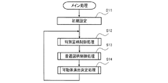
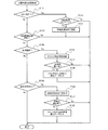
[メイン処理]
最初に、図10に示すように、RAMアクセス許可、バックアップ復帰処理、作業領域を初期化等の初期設定処理を実行する(ステップS11)。そして、詳しくは図12を用いて後述するが、特別図柄ゲームの進行、液晶表示装置32、特別図柄表示器33に表示される特別図柄、装飾図柄に関する特別図柄制御処理を実行する(ステップS12)。そして、詳しくは、図14を用いて後述するが、普通図柄ゲームの進行、普通図柄表示器35に表示される普通図柄に関する普通図柄制御処理を実行する(ステップS13)。そして、詳しくは、図16を用いて後述するが、可動体80,96による演出の実行を制御する可動体演出決定処理を実行する(ステップS14)。このように、メイン処理においては、ステップS11の初期設定処理が終了した後、ステップS12〜ステップS14の処理を繰り返し実行することとなる。
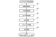
[システムタイマ割込処理]
また、メインCPU66は、メイン処理を実行している状態であっても、メイン処理を中断させ、システムタイマ割込処理を実行する場合がある。リセット用クロックパルス発生回路62から所定の周期(例えば2ミリ秒)毎に発生されるクロックパルスに応じて、以下のシステムタイマ割込処理を実行する。このシステムタイマ割込処理について図11を用いて説明する。
In this embodiment, the main control circuit 60 uses the main ROM 68 and the sub control circuit 200 uses the program ROM 208 as storage means for storing programs, tables, and the like. However, the present invention is not limited to this. As long as it is a storage medium readable by a computer equipped with a computer, a program, a table, and the like are recorded on a storage medium such as a hard disk device, a CD-ROM and a DVD-ROM, and a ROM cartridge. May be. Further, these programs may not be recorded in advance, but may be downloaded after the power is turned on and recorded in the main RAM 70 in the main control circuit 60 and the work RAM 210 in the sub control circuit 200. . In this embodiment, the main RAM 70 is used as the temporary storage area of the main CPU 66 and the work RAM 210 is used as the temporary storage area of the sub CPU 206. However, the present invention is not limited to this, and any readable / writable storage medium may be used.
[Game machine operation]
In the present embodiment, as described above, the gaming state is roughly divided into a general gaming state and a jackpot gaming state. Further, even in the general game state, three game states are provided: a normal mode, a probability change mode, and a time reduction mode. The processing executed in the pachinko gaming machine 10 is shown below in FIGS.
[Main processing]
First, as shown in FIG. 10, initial setting processing such as RAM access permission, backup restoration processing, and work area initialization is executed (step S11). Then, as will be described in detail later with reference to FIG. 12, a special symbol control process relating to the progress of the special symbol game, the special symbol displayed on the liquid crystal display device 32 and the special symbol display 33, and the decorative symbol is executed (step S12). . Then, as will be described in detail later with reference to FIG. 14, the normal symbol control process relating to the progress of the normal symbol game and the normal symbol displayed on the normal symbol display 35 is executed (step S13). Then, as will be described in detail later with reference to FIG. 16, a movable body effect determination process for controlling the execution of effects by the movable bodies 80 and 96 is executed (step S14). Thus, in the main process, after the initial setting process in step S11 is completed, the processes in steps S12 to S14 are repeatedly executed.
[System timer interrupt processing]
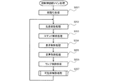
Further, the main CPU 66 may interrupt the main process and execute the system timer interrupt process even when the main process is being executed. The following system timer interrupt process is executed in response to a clock pulse generated from the reset clock pulse generation circuit 62 every predetermined period (for example, 2 milliseconds). This system timer interrupt process will be described with reference to FIG.

最初に、図11に示すように、メインCPU66は、大当り判定用乱数カウンタ、大当り図柄決定用乱数カウンタ等の各カウント値を“1”増加するように乱数更新処理を実行する(ステップS21)。そして、メインCPU66は、始動口25等への遊技球の入賞
を検知する入力検出処理を実行する(ステップS22)。この処理においては、メインCPU66は、各種の入賞口に遊技球が入賞したことを条件として、遊技球を払出す(賞球する)旨のデータをメインRAM70の所定領域に記憶することとなる。そして、主制御回路60と副制御回路200との同期をとるための待ち時間タイマ、大当りが発生した際に開放する大入賞口39の開放時間を計測するための大入賞口開放タイマ等、各種のタイマの更新処理を実行する(ステップS23)。そして、各種の変数に基づいて駆動制御するための信号をソレノイド、モータ等に供給するために、出力処理を実行する(ステップS24)。この処理が終了した場合には、ステップS25に処理を移す。
First, as shown in FIG. 11, the main CPU 66 executes a random number update process so as to increase the count values of the big hit determination random number counter, the big hit symbol determination random number counter, etc. by “1” (step S21). Then, the main CPU 66 executes an input detection process for detecting a winning of a game ball to the start opening 25 or the like (step S22). In this processing, the main CPU 66 stores in the predetermined area of the main RAM 70 data for paying out the game balls (winning the game balls) on the condition that the game balls have won the various winning ports. Various types of timers such as a waiting time timer for synchronizing the main control circuit 60 and the sub control circuit 200, a big prize opening timer for measuring the opening time of the big prize opening 39 that is opened when a big hit occurs, etc. The timer update process is executed (step S23). Then, an output process is executed in order to supply a signal for drive control based on various variables to a solenoid, a motor, and the like (step S24). If this process ends, the process moves to a step S25.

ステップS25においては、コマンド出力処理を実行する。この処理において、メインCPU66は、各種のコマンドを副制御回路200に供給する。これらの各種のコマンドとしては、具体的には、デモ表示コマンド、導出表示される特別図柄の種類を示す導出図柄指定コマンド、可動体80,96により実行される可動体演出指定コマンド等が含まれる。この処理が終了した場合には、ステップS26に処理を移す。   In step S25, command output processing is executed. In this process, the main CPU 66 supplies various commands to the sub control circuit 200. Specifically, these various commands include a demonstration display command, a derived symbol designation command indicating the type of special symbol derived and displayed, a movable body effect designation command executed by the movable bodies 80 and 96, and the like. . If this process ends, the process moves to a step S26.

そして、ステップS26の処理において、メインCPU66は、払出装置128に賞球を行わせるための賞球制御コマンドを払出・発射制御回路126へ送信する等の払出処理を実行する。具体的には、メインCPU66は、各種の入賞口に遊技球が入賞することで予め設定された所定数の賞球払出を行うための賞球制御コマンドを払出・発射制御回路126へ供給する。この処理が終了した場合には、本サブルーチンを終了し、割込発生前のアドレスへ復帰し、メイン処理を実行させる。
[特別図柄制御処理]
図10のステップS12において実行される特別図柄制御処理について図12を用いて説明する。
In step S26, the main CPU 66 executes a payout process such as transmitting a prize ball control command for causing the payout device 128 to perform a prize ball to the payout / firing control circuit 126. Specifically, the main CPU 66 supplies to the payout / firing control circuit 126 a prize ball control command for paying out a predetermined number of prize balls as a result of the game balls winning in various winning holes. When this process is finished, this subroutine is finished, the address is returned to the address before the occurrence of the interrupt, and the main process is executed.
[Special symbol control processing]
The special symbol control process executed in step S12 of FIG. 10 will be described with reference to FIG.

最初に、図12に示すように、特別図柄制御フラグをロードする(ステップS31)。この処理において、メインCPU66は、特別図柄制御フラグを読み出しステップS32に処理を移す。   First, as shown in FIG. 12, a special symbol control flag is loaded (step S31). In this process, the main CPU 66 reads the special symbol control flag and moves the process to step S32.

ステップS32においては、メインCPU66は、特別図柄制御フラグが(00)であるか否か判断し、(00)の場合には、ステップS33へ処理を移し、特別図柄記憶チェック処理を行う。この特別図柄記憶チェック処理では、詳細は後述するが、特別図柄の保留個数を調べ、保留個数がある場合に、大当り判定、特別図柄の変動開始、特別図柄変動タイマのセット等を行い、特別図柄制御フラグに次のステップの処理要求である(01)をセットして処理を終了する。また、特別図柄制御フラグが(00)でない場合には、ステップS34に処理を移す。   In step S32, the main CPU 66 determines whether or not the special symbol control flag is (00). If it is (00), the main CPU 66 moves the process to step S33 and performs a special symbol storage check process. Although the details will be described later in this special symbol memory check process, the number of special symbols held is checked, and if there is a number of reserves, the jackpot judgment, special symbol variation start, special symbol variation timer is set, etc. The processing flag is set to (01), which is the processing request for the next step, and the processing is terminated. If the special symbol control flag is not (00), the process proceeds to step S34.

ステップS34においては、メインCPU66は、特別図柄制御フラグが(01)であるか否か判断し、(01)でない場合には、ステップS40に処理を移す。また、特別図柄制御フラグが(01)の場合には、特別図柄変動時間監視処理を行う。ステップS35においては、特別図柄変動タイマがタイムアップ(つまり“0”)か否か判断し、タイムアップしていなければ処理を終了する。そしてタイムアップした場合は、メインCPU66は、ステップS36で特別図柄の停止処理を行うとともに、メインRAM70に記憶されている特別図柄保留個数を“1”減少するように記憶更新する。さらに、メインCPU66は、遊技状態フラグが時短モードであるか判断し、時短モードの場合はメインRAM70に記憶されている時短回数を“1”減少するように記憶更新し、そして、時短回数が“0”(つまり時短モードの終了)になった場合は、遊技状態フラグを通常モードにセットして、時短モードを終了させる。   In step S34, the main CPU 66 determines whether or not the special symbol control flag is (01). If not (01), the main CPU 66 moves the process to step S40. When the special symbol control flag is (01), special symbol variation time monitoring processing is performed. In step S35, it is determined whether or not the special symbol variation timer has timed up (that is, "0"). If the time has not expired, the process ends. When the time is up, the main CPU 66 performs a special symbol stop process in step S36 and updates the special symbol holding number stored in the main RAM 70 so as to decrease by "1". Further, the main CPU 66 determines whether or not the game state flag is in the time reduction mode. If the game time flag is in the time reduction mode, the main CPU 66 updates the memory so that the number of time reductions stored in the main RAM 70 is decreased by “1”. When it becomes 0 "(that is, the end of the time reduction mode), the gaming state flag is set to the normal mode, and the time reduction mode is ended.

次に、メインCPU66は、ステップS37において特別図柄が大当たりかどうか判断し、大当たりでなければステップS39において、特別図柄制御フラグをクリア(つまり特別図柄記憶チェック処理を要求する値(00)をセットする)して処理を終了する。そして大当たりであった場合は、ステップS38の大入賞口開放待ち処理を行う。大入賞口開放待ち処理では、メインCPU66は、特別図柄制御フラグに大入賞口開放待ちを示す値(02)をセットし、待ち時間(例えば1秒)を大入賞口開放待ちタイマにセットして処理を終了する。   Next, the main CPU 66 determines whether or not the special symbol is a big hit in step S37. If the big symbol is not a big hit, the main CPU 66 clears the special symbol control flag (that is, sets the value (00) for requesting the special symbol storage check process) in step S39. ) To finish the process. If it is a big win, a special winning opening release waiting process in step S38 is performed. In the special winning opening release waiting process, the main CPU 66 sets a value (02) indicating waiting for the special winning opening to the special symbol control flag, and sets a waiting time (for example, 1 second) in the special winning opening release waiting timer. The process ends.

ステップS40においては、メインCPU66は、特別図柄制御フラグが(02)であるか否か判断し、(02)の場合には、大入賞口開放処理を行う。大入賞口開放処理では、まず、メインCPU66は、ステップS41で大入賞口開放待ちタイマがタイムアップ(つまり“0”)か否かを判断し、タイムアップしていなければ処理を終了する。一方、タイムアップした場合は、ステップS42で大入賞口開放処理を行う。この大入賞口開放処理では、メインCPU66は、まず大入賞口の開放をセット(メインRAM70の所定の領域に、シャッタ40による大入賞口ソレノイド120の開放指示を記憶する)し、次に大当たりの種類によって大入賞口開放タイマに大入賞口の開放時間(例えば、大当たりが15R確変大当たり、または15R普通大当たりの場合は30秒、2R確変大当たりの場合は2秒)をセットする。そして、特別図柄制御フラグに大入賞口開放監視処理を示す値(03)をセットし処理を終了する。また、特別図柄制御フラグが(02)でない場合には、ステップS43に処理を移す。   In step S40, the main CPU 66 determines whether or not the special symbol control flag is (02). In the case of (02), the main CPU 66 performs a big prize opening process. In the big prize opening process, first, the main CPU 66 determines in step S41 whether or not the big prize opening waiting timer is timed up (that is, “0”). If the time is not up, the process is terminated. On the other hand, if the time is up, a special winning opening release process is performed in step S42. In this special winning opening opening process, the main CPU 66 first sets the opening of the special winning opening (stores the opening instruction of the special winning opening solenoid 120 by the shutter 40 in a predetermined area of the main RAM 70), and then the big win. Depending on the type, the opening time of the big prize opening is set in the big prize opening timer (for example, 30 seconds if the jackpot is 15R probability variation jackpot, or 15R normal jackpot, 2 seconds if 2R probability variation jackpot). Then, the special symbol control flag is set to a value (03) indicating the special winning opening release monitoring process, and the process ends. If the special symbol control flag is not (02), the process proceeds to step S43.

ステップS43においては、メインCPU66は、特別図柄制御フラグが(03)であるか否か判断し、(03)でない場合には、ステップS50に処理を移す。また、特別図柄制御フラグが(03)の場合には、大入賞口開放監視処理を行う。大入賞口開放監視処理では、まずメインCPU66は、ステップS44で大入賞口開放タイマがタイムアップ(つまり“0”)か、または、大入賞口へ規定の個数の遊技球が入賞したかを判断する。そして大入賞口開放タイマのタイムアップ、同時に、大入賞口へ規定の個数の遊技球が入賞していなければ処理を終了する。そして入賞口開放タイマのタイムアップ、または、大入賞口へ規定の個数の遊技球が入賞のいずれか一方の条件を満たしたことで、ステップS45へ処理を移行する。   In step S43, the main CPU 66 determines whether or not the special symbol control flag is (03). If not (03), the main CPU 66 shifts the processing to step S50. When the special symbol control flag is (03), a special winning opening opening monitoring process is performed. In the special winning opening opening monitoring process, first, the main CPU 66 determines in step S44 whether the special winning opening release timer is timed up (that is, “0”) or whether a prescribed number of game balls have won the special winning opening. To do. Then, the time of the grand prize opening timer expires, and at the same time, if the prescribed number of game balls have not won the big prize opening, the process is terminated. Then, the process proceeds to step S45 when the winning opening timer expires or when a prescribed number of game balls satisfy the winning condition.

ステップS45においては、メインCPU66は、大入賞口閉鎖処理(メインRAM70の所定の領域に、シャッタ40による大入賞口ソレノイド120の閉鎖指示を記憶する)を実行してステップS46へ処理を移す。   In step S45, the main CPU 66 executes a special winning opening closing process (stores a closing instruction of the special winning opening solenoid 120 by the shutter 40 in a predetermined area of the main RAM 70), and moves the process to step S46.

ステップS46においては、メインCPU66は、大入賞口開放回数(所謂ラウンド数)をカウントし、規定回数(15R通常大当たりまたは15R確変大当たりでは15回、2R確変大当たりでは2回)に達したか否かを判断し、規定回数に達した場合はステップS49で特別図柄制御フラグに大当たり終了処理を要求する値(04)をセットし処理を終了する。また、メインCPU66は、大入賞口開放回数が規定回数に達していなかった場合は、ステップS47で、大入賞口へ入賞した遊技球が所定の特定領域を通過したかどうかを判断し、大入賞口へ入賞した遊技球が所定の特定領域を通過しなかった場合(V・カウントセンサ102が遊技球の通過を検出しなかった場合)は、ステップS49で特別図柄制御フラグに大当たり終了処理を要求する値(04)をセットし処理を終了する。一方、メインCPU66は、大入賞口へ入賞した遊技球が所定の特定領域を通過した(つまり、V・カウントセンサ102が遊技球の通過を検出した)場合は、ステップS48へ処理を移す。   In step S46, the main CPU 66 counts the number of times that the special winning opening is opened (the so-called number of rounds), and whether or not the specified number of times (15 times for the 15R normal jackpot or 15R probability variation jackpot, 2 times for the 2R probability variation jackpot) is reached. In step S49, the special symbol control flag is set to a value (04) for requesting the jackpot end process, and the process ends. On the other hand, if the number of times of opening of the big winning opening has not reached the prescribed number, the main CPU 66 determines whether or not the game ball that has won the big winning opening has passed a predetermined specific area in step S47. If the game ball won in the mouth does not pass the predetermined specific area (when the V / count sensor 102 does not detect the game ball passing), the special symbol control flag is requested to end the jackpot in step S49. A value (04) to be set is set, and the process ends. On the other hand, the main CPU 66 moves the process to step S48 when the game ball that has won the special winning opening passes a predetermined specific area (that is, the V / count sensor 102 detects the passage of the game ball).

ステップS48では、メインCPU66は、大入賞口開放待ち処理を行う。大入賞口開放待ち処理では、特別図柄制御フラグに再度大入賞口の開放を要求する値(02)をセットし、待ち時間(例えば1秒)を大入賞口開放待ちタイマにセットして処理を終了する。   In step S48, the main CPU 66 performs a special winning opening opening waiting process. In the special winning opening release waiting process, the special symbol control flag is again set to the value (02) for requesting the opening of the special winning opening, and the waiting time (for example, 1 second) is set in the special winning opening release waiting timer. finish.

ステップS50においては、メインCPU66は、大当たり終了処理を行う。大当たり終了処理では、大当たり図柄が15R確変大当たりまたは2R確変大当たりの場合は、遊技状態フラグを確変モードとし、大当たり図柄が15R通常大当たりの場合には、遊技状態フラグを時短モードとして、さらに時短モード中の特別図柄の変動回数の上限(例えば100回)をメインRAM70の所定の領域に記憶する。最後にメインCPU66は、特別図柄制御フラグをクリア(つまり特別図柄記憶チェック処理を要求する値(00)をセットする)して、特別図柄制御処理を終了する。
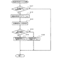
[特別図柄記憶チェック処理]
図12のステップS33において実行される特別図柄記憶チェック処理について図13を用いて説明する。
In step S50, the main CPU 66 performs jackpot end processing. In the jackpot end process, if the jackpot symbol is 15R probability variation jackpot or 2R probability variation jackpot, the gaming state flag is set to the probability variation mode. The upper limit (for example, 100 times) of the variation number of the special symbol is stored in a predetermined area of the main RAM 70. Finally, the main CPU 66 clears the special symbol control flag (that is, sets a value (00) for requesting the special symbol storage check process), and ends the special symbol control process.
[Special symbol memory check processing]
The special symbol memory check process executed in step S33 in FIG. 12 will be described with reference to FIG.

最初に、メインCPU66は、図13に示すように、特別図柄保留個数が“0”であるか否かの判断を行い、特別図柄の保留個数が“0”の場合には、ステップS62に処理を移し、特別図柄の保留個数が“0”でない場合(つまり、特別図柄の変動がある場合)には、ステップS63に処理を移す。   First, as shown in FIG. 13, the main CPU 66 determines whether or not the number of special symbol reservations is “0”. If the number of special symbol reservations is “0”, the main CPU 66 proceeds to step S62. If the number of reserved special symbols is not “0” (that is, if there is a change in special symbols), the process proceeds to step S63.

ステップS62においては、デモ表示処理を実行する。この処理において、メインCPU66は、デモ表示を行わせるために、副制御回路200にデモ表示コマンドを供給するためのデータを、メインRAM70の所定の領域に記憶する。これによって、副制御回路200において、客待ち状態(所定の待機状態)となったことを認識することができる。この処理が終了した場合には、特別図柄記憶チェック処理を終了する。   In step S62, a demonstration display process is executed. In this process, the main CPU 66 stores data for supplying a demo display command to the sub-control circuit 200 in a predetermined area of the main RAM 70 in order to perform a demo display. As a result, the sub-control circuit 200 can recognize that the customer waiting state (predetermined waiting state) has been reached. When this process ends, the special symbol storage check process ends.

ステップS63においては、メインCPU66は、特別図柄変動時間管理を要求する値(01)を、特別図柄制御フラグにセットする。この処理が終了した場合には、ステップS64に処理を移す。   In step S63, the main CPU 66 sets a value (01) for requesting special symbol variation time management to the special symbol control flag. If this process ends, the process moves to a step S64.

ステップS64においては、大当り判定処理を実行する。この処理において、メインCPU66は、遊技状態フラグを読み出し、読み出した遊技状態フラグに基づいて、大当りの判定値の数が異なる複数の大当り判定テーブル(図9(a)参照)から1つの大当り判定テーブルを選択する。そして、始動口25へ遊技球が入賞した時に抽出された大当り図柄用乱数値と、前記選択された大当たり判定テーブルを参照し、大当たりを判定(15R確変大当たり、2R確変大当たり、15R通常大当たりまたは“はずれ”のうちのいずれかを決定)する。ここで、図9(a)の大当たり判定テーブルに示すように、通常モードまたは時短モードにおける大当り判定テーブルと確変モードにおける大当り判定テーブルでは、大当たりの判定値は、通常モードでは7/400(15R通常大当たり、15R確変大当たり及び2R確変大当たりの全て大当たり判定値の合計)に設定されているのに対し、確変モードでは70/400(15R通常大当たり、15R確変大当たり及び2R確変大当たりの全て大当たり判定値の合計)と設定されている。つまり遊技状態フラグに基づいて大当り判定テーブルを選択することによって、大当り遊技状態に移行する確率が異なることとなる。このように、遊技状態フラグが確変モードである場合には、大当り遊技状態に移行する確率は、通常モードよりも向上することとなるので、遊技者にとって有利な状態といえる。この処理が終了した場合には、ステップS65に処理を移す。   In step S64, a big hit determination process is executed. In this process, the main CPU 66 reads out the game state flag and, based on the read game state flag, one jackpot determination table from a plurality of jackpot determination tables (see FIG. 9A) with different numbers of jackpot determination values. Select. Then, with reference to the jackpot symbol random number extracted when the game ball wins the starting opening 25 and the selected jackpot determination table, the jackpot is determined (15R probability variable jackpot, 2R probability variable jackpot, 15R normal jackpot or “ Determine one of the “out of”. Here, as shown in the jackpot determination table in FIG. 9A, in the jackpot determination table in the normal mode or the short time mode and the jackpot determination table in the probability variation mode, the jackpot determination value is 7/400 (15R normal in the normal mode). It is set to jackpot, 15R probability variation jackpot and 2R probability variation jackpot all jackpot judgment value), but in probability variation mode 70/400 (15R normal jackpot, 15R probability variation jackpot and 2R probability variation jackpot all jackpot judgment value) Total). That is, by selecting the jackpot determination table based on the gaming state flag, the probability of shifting to the jackpot gaming state will be different. Thus, when the gaming state flag is in the probability variation mode, the probability of shifting to the big hit gaming state is improved as compared with the normal mode, which can be said to be an advantageous state for the player. If this process ends, the process moves to a step S65.

ステップS65においては、メインCPU66は、大当たりであるか否かの判断処理を行う。この処理において、メインCPU66は、ステップS64の判定の結果が大当りであった場合には、ステップS66に処理を移し、大当りでなかった場合には、ステップS67に処理を移す。   In step S65, the main CPU 66 determines whether or not it is a big hit. In this process, the main CPU 66 moves the process to step S66 if the result of the determination in step S64 is a big hit, and moves the process to step S67 if not the big win.

ステップS66においては、特定図柄の決定処理を実行する。この処理において、メインCPU66は、ステップS64で決定された大当たりの種類に対応して表示される特定図柄を決定する。例えば、15R確変大当たりに対しては、特定図柄は“7”が決定され、2R確変大当たりに対しては、特定図柄は“3”、または、15R通常大当たりに対しては、特定図柄は“5”というように、それぞれの大当たりに対応して特定図柄は決定される。そして、決定された特定図柄は、メインRAM70の所定領域に記憶される。これによって、特別図柄表示器33に、大当たりに対応した特定図柄が導出表示されることとなる。この処理が終了した場合には、ステップS68に処理を移す。   In step S66, a specific symbol determination process is executed. In this process, the main CPU 66 determines a specific symbol to be displayed corresponding to the jackpot type determined in step S64. For example, for the 15R probability variable jackpot, the specific symbol is determined as “7”, for the 2R probability variable jackpot, the specific symbol is “3”, or for the 15R normal jackpot, the specific symbol is “5”. "A specific symbol is determined corresponding to each jackpot. The determined specific symbol is stored in a predetermined area of the main RAM 70. As a result, the special symbol corresponding to the jackpot is derived and displayed on the special symbol display 33. If this process ends, the process moves to a step S68.

ステップS67においては、はずれ図柄の決定処理を実行する。この処理において、メインCPU66は、はずれ図柄に対応した特定図柄(例えば“7”、“3”、“5”以外の数字)を決定し、メインRAM70の所定領域に記憶する。これによって、特別図柄表示器33に、はずれに対応した特定図柄が導出表示されることとなる。この処理が終了した場合には、ステップS68に処理を移す。   In step S67, a missing symbol determination process is executed. In this process, the main CPU 66 determines a specific symbol (for example, a number other than “7”, “3”, “5”) corresponding to the off symbol and stores it in a predetermined area of the main RAM 70. As a result, a special symbol corresponding to the deviation is derived and displayed on the special symbol display 33. If this process ends, the process moves to a step S68.

ステップS68では、遊技状態判別処理を行う。この遊技状態判別処理において、メインCPU66は、現在の遊技状態フラグが、確変モードもしくは時短モードであると判断した場合は、ステップS70へ処理を移行し、通常モードであると判断した場合は、ステップS69において、通常モードの特別図柄変動時間(例えば10秒)を、特別図柄変動タイマに記憶する。そして、ステップS71へ処理を移行する。   In step S68, a gaming state determination process is performed. In this gaming state determination process, the main CPU 66 proceeds to step S70 when it is determined that the current gaming state flag is in the probability variation mode or the short time mode, and when it is determined that it is in the normal mode, the step In S69, the special symbol variation time in the normal mode (for example, 10 seconds) is stored in the special symbol variation timer. Then, the process proceeds to step S71.

ステップS70においては、メインCPU66は、確変モードまたは時短モードの特別図柄変動時間(通常モードの特別図柄変動時間より短い時間、例えば5秒)を、特別図柄変動タイマに記憶する。そして、ステップS71へ処理を移行する。   In step S70, the main CPU 66 stores the special symbol variation time in the probability variation mode or the short time mode (a time shorter than the special symbol variation time in the normal mode, for example, 5 seconds) in the special symbol variation timer. Then, the process proceeds to step S71.

ステップS71では、液晶表示装置32に演出表示される装飾図柄や演出時間の決定処理を行う。この処理において、メインCPU66は、ステップS66またはステップS67で記憶された“大当たり”または“はずれ”のデータ、そしてステップS69またはステップS70で記憶された特別図柄変動時間等のデータを、図11のステップS25のコマンド出力処理により、主制御回路60のメインCPU66から副制御回路200のサブCPU206に導出図柄指定コマンドとして供給する。これによって、副制御回路200において、装飾図柄が液晶表示装置32に導出表示されるとともに、またその装飾図柄の変動時間も決定されることとなる。つまり、特別図柄表示器33で導出表示される特別図柄の変動時間と、液晶表示装置32に導出表示される装飾図柄の変動時間は、同期して行われることとなる。
[普通図柄制御処理]
図10のステップS13において実行されるサブルーチンについて図14を用いて説明する。
In step S71, a process of determining a decorative symbol and effect time displayed on the liquid crystal display device 32 is performed. In this process, the main CPU 66 uses the data of “big hit” or “out of place” stored in step S66 or step S67, and the special symbol variation time stored in step S69 or step S70 as the step of FIG. By the command output process of S25, the main CPU 66 of the main control circuit 60 supplies the sub CPU 206 of the sub control circuit 200 as a derived symbol designation command. As a result, in the sub control circuit 200, the decorative symbol is derived and displayed on the liquid crystal display device 32, and the variation time of the decorative symbol is also determined. That is, the variation time of the special symbol derived and displayed on the special symbol display device 33 and the variation time of the decorative symbol derived and displayed on the liquid crystal display device 32 are synchronized.
[Normal symbol control processing]
The subroutine executed in step S13 in FIG. 10 will be described with reference to FIG.

最初に、図14に示すように、普通図柄制御フラグをロードする(ステップS101)。この処理において、メインCPU66は、普通図柄制御フラグを読み出す。この処理が終了した場合には、ステップS102に処理を移す。   First, as shown in FIG. 14, the normal symbol control flag is loaded (step S101). In this process, the main CPU 66 reads the normal symbol control flag. If this process ends, the process moves to a step S102.

ステップS102においては、メインCPU66は、普通図柄制御フラグが普通図柄記憶チェック要求を示す値(00)である場合に、ステップ103の普通図柄記憶チェック処理を行う、この普通図柄記憶チェック処理は、詳しくは図15を用いて説明するが、普通図柄の保留個数がある場合の当り判定等を行う。この処理が終了した場合には、処理を終了する。また普通図柄制御フラグが(00)でない場合は、ステップS104へ処理を移す。   In step S102, when the normal symbol control flag is a value (00) indicating a normal symbol storage check request, the main CPU 66 performs the normal symbol storage check processing in step 103. This normal symbol storage check processing is detailed. Will be described with reference to FIG. 15, and a hit determination or the like is performed when there is a reserved number of normal symbols. When this process ends, the process ends. If the normal symbol control flag is not (00), the process proceeds to step S104.

ステップS104においては、メインCPU66は、普通図柄制御フラグが(01)であるか否か判断し、普通図柄制御フラグが(01)でない場合は、ステップS107へ処理を移す。また、普通図柄制御フラグが(01)である場合、ステップS105の普通図柄変動タイマがタイムアップ(つまり“0”)したか否かを判断し、タイムアップしなかった場合は処理を終了する。一方、タイムアップした場合は、メインCPU66は、ステップS106で普通図柄に対して普通図柄変動停止処理を行うとともに、メインRAM70の普通図柄保留個数を“1”減少するように記憶更新する。そして、普通図柄制御フラグに(02)をセットして処理を終了する。   In step S104, the main CPU 66 determines whether or not the normal symbol control flag is (01). If the normal symbol control flag is not (01), the process proceeds to step S107. If the normal symbol control flag is (01), it is determined whether or not the normal symbol variation timer in step S105 has timed up (that is, “0”). If the time has not expired, the process ends. On the other hand, when the time is up, the main CPU 66 performs the normal symbol variation stop process for the normal symbols in step S106 and also updates the stored number of normal symbols in the main RAM 70 so as to decrease by “1”. Then, (02) is set in the normal symbol control flag and the process is terminated.

ステップS107においては、メインCPU66は、普通図柄制御フラグが(02)であるか否かを判断する。そして、普通図柄制御フラグが(02)でない場合は、ステップS111へ処理を移す。また、普通図柄制御フラグが(02)であった場合は、ステップS108へ処理を移し、普通図柄が当りか否かを判断する。そして、メインCPU66は、当りである場合に、ステップS109の普通電役開放処理に処理を移す。一方、メインCPU66は、当りではないと判断すると、普通図柄制御フラグに普通図柄記憶チェックを要求する値(00)をセットして処理を終了する。   In step S107, the main CPU 66 determines whether or not the normal symbol control flag is (02). If the normal symbol control flag is not (02), the process proceeds to step S111. If the normal symbol control flag is (02), the process proceeds to step S108 to determine whether or not the normal symbol is a hit. If the main CPU 66 is successful, the main CPU 66 shifts the processing to the normal electric power releasing process of step S109. On the other hand, if the main CPU 66 determines that it is not a win, it sets the value (00) for requesting the normal symbol storage check to the normal symbol control flag and ends the process.

ステップS109における普通電動役物開放処理では、メインCPU66は、普通電動役物の羽根部材23の開放処理(メインRAMの所定の領域に普通電動役物の解放を記憶する)を行う。さらに遊技台の遊技状態に合わせて、普通電動役物の羽根部材23の開放時間(例えば、遊技状態が確変モードまたは時短モードの場合は3秒、通常モードの場合は0.2秒)を普通電動役物開放タイマにセットし、普通図柄制御フラグに(03)をセットし処理を終了する。   In the ordinary electric actor release process in step S109, the main CPU 66 performs the opening process of the blade member 23 of the ordinary electric actor (stores the release of the ordinary electric actor in a predetermined area of the main RAM). Furthermore, the opening time of the blade member 23 of the ordinary electric accessory (for example, 3 seconds when the game state is the probability change mode or the short time mode, 0.2 seconds when the game mode is the normal mode) according to the game state of the game table is normal. The electric accessory release timer is set, the normal symbol control flag is set to (03), and the process is terminated.

ステップS111においては、メインCPU66は、普通図柄制御フラグが(03)であるか否かを判断する。そして、普通図柄制御フラグが(03)でない場合は、ステップS114へ処理を移す。また、普通図柄制御フラグが(03)であった場合は、ステップS112へ処理を移し、普通電動役物開放タイマがタイムアップ(つまり“0”)かを判断する。そして、普通電動役物開放タイマがタイムアップしていない場合は処理を終了する。さらに、普通電動役物開放タイマがタイムアップしたと判断した場合は、ステップS113へ処理を移し、普通電動役物である羽根部材23を閉鎖状態(メインRAMの所定の領域に普通電動役物の閉鎖を記憶する)にさせる。そして普通図柄制御フラグに(04)をセットして処理を終了する。   In step S111, the main CPU 66 determines whether or not the normal symbol control flag is (03). If the normal symbol control flag is not (03), the process proceeds to step S114. If the normal symbol control flag is (03), the process proceeds to step S112, and it is determined whether the normal electric accessory release timer is up (that is, "0"). Then, if the normal electric accessory release timer has not expired, the process is terminated. Further, if it is determined that the normal electric accessory release timer has timed up, the process proceeds to step S113, and the blade member 23, which is an ordinary electric accessory, is closed (the normal electric accessory is not stored in a predetermined area of the main RAM). Remember the closure). Then, (04) is set in the normal symbol control flag and the process is terminated.

ステップS114においては、メインCPU66は、普通図柄制御フラグをクリア(つまり普通図柄の記憶チェックを要求する値“00”をセット)して処理を終了する。
[普通図柄記憶チェック処理]
図14のステップS103において実行されるサブルーチンについて図15を用いて説明する。
In step S114, the main CPU 66 clears the normal symbol control flag (that is, sets the value “00” for requesting the normal symbol storage check) and ends the process.
[Normal symbol memory check processing]
The subroutine executed in step S103 in FIG. 14 will be described with reference to FIG.

最初に、ステップS121において、メインCPU66は、普通図柄保留個数が“0”であるか否かの判断を行い、普通図柄保留個数が“0”であると判断した場合には、普通図柄記憶チェック処理を終了する。尚、この普通図柄保留個数はメインRAMの所定の領域に記憶され、通過ゲート54を遊技球が通過したことを検出した場合に、所定個数(例えば“4”)を上限として“1”増加して記憶更新され、普通図柄ゲームにおける普通図柄の可変表示が終了したときには、“1”減算して記憶更新される。一方、メインCPU66は、普通図柄の保留個数が“0”であるとは判別しなかった場合には、ステップS122において、普通図柄制御フラグに普通図柄変動タイマ監視要求の値“01”をセットし、ステップS123へ処理を移す。   First, in step S121, the main CPU 66 determines whether or not the normal symbol holding number is “0”. If it is determined that the normal symbol holding number is “0”, the normal symbol storage check is performed. The process ends. This normal symbol holding number is stored in a predetermined area of the main RAM, and when it is detected that a game ball has passed through the passing gate 54, the predetermined symbol (for example, “4”) is increased by “1”. When the variable display of the normal symbol in the normal symbol game is completed, “1” is subtracted and the memory is updated. On the other hand, if the main CPU 66 does not determine that the number of retained normal symbols is “0”, the normal symbol variation timer monitoring request value “01” is set in the normal symbol control flag in step S122. Then, the process proceeds to step S123.

ステップS123においては、普通図柄当り判定処理を実行する。この処理において、メインCPU66は、普通図柄始動領域通過時に(通過ゲート54を遊技球が通過することによって)抽出された普通図柄当り判定用乱数値と、メインROM68に記憶されている普通図柄当り判定値とを参照する。そして、メインCPU66は、参照した結果、普通図柄当り判定用乱数値が普通図柄当り判定値と一致する場合には、当り図柄(例えば、“○”図柄)を示すデータをメインRAMの所定の領域に記憶する。一方、メインCPU66は、参照した結果、普通図柄当り判定用乱数値が普通図柄当り判定値と一致しない場合には、はずれ図柄(例えば、“×”図柄)を示すデータをメインRAMの所定の領域に記憶する。このように記憶された当り図柄、はずれ図柄は、普通図柄表示器35に導出普通図柄指定コマンドとして供給される。これによって、普通図柄表示器35は、普通図柄の変動表示(例えば“○”、“×”図柄を交互に点滅させる)を開始する。この後ステップS124に処理を移す。   In step S123, a normal symbol hit determination process is executed. In this processing, the main CPU 66 determines the normal symbol per-determining random number extracted when the normal symbol starting region passes (by passing the game ball through the passing gate 54) and the normal symbol per-unit determination stored in the main ROM 68. Refers to the value. Then, as a result of the reference, when the random value for determination per ordinary symbol matches the determination value per ordinary symbol as a result of the reference, the main CPU 66 stores data indicating the winning symbol (for example, “◯” symbol) in a predetermined area of the main RAM. To remember. On the other hand, as a result of the reference, if the random value for determination per normal symbol does not match the determination value per normal symbol as a result of the reference, the main CPU 66 stores data indicating the off symbol (for example, “×” symbol) in a predetermined area of the main RAM. To remember. The winning symbol and the off symbol stored in this manner are supplied to the normal symbol display 35 as a derived normal symbol designation command. As a result, the normal symbol display 35 starts normal symbol variation display (for example, “◯” and “x” symbols are alternately blinked). Thereafter, the process proceeds to step S124.

ステップS124においては、メインCPUは、遊技状態フラグが確変モードまたは時短モードであるか否かを判断する。遊技状態フラグが確変モードまたは時短モードであった場合は、S126で通常モードより短い普通図柄変動停止時間(例えば5秒)が、普通図柄変動タイマにセットされ処理を終了する。一方、遊技状態が確変モードまたは時短モードで無い(つまり通常モード)場合は、ステップS125で確変モードまたは時短モードより長い普通図柄変動停止時間(例えば30秒)が、普通図柄変動タイマにセットされ処理を終了する。   In step S124, the main CPU determines whether or not the gaming state flag is in the probability change mode or the time reduction mode. When the game state flag is in the probability variation mode or the time reduction mode, the normal symbol variation stop time (for example, 5 seconds) shorter than the normal mode is set in the normal symbol variation timer in S126, and the processing is ended. On the other hand, if the gaming state is not the probability variation mode or the time reduction mode (that is, the normal mode), a normal symbol variation stop time (for example, 30 seconds) longer than the probability variation mode or the time reduction mode is set in the normal symbol variation timer and processed Exit.

ここで、パチンコ遊技機10における遊技状態フラグについて説明する。前述したように、パチンコ遊技機10における遊技状態フラグには、通常モード、確変モードおよび時短モードのいずれかが設定される。図7(a)によると、各遊技モードでは遊技者に有利な状態である大当たりを判定する数値が異なっている、つまり確変モードでは、大当たりを判定する数値が70/400(15R通常大当たり、2R確変大当たり、15R確変大当たりの全ての数値の合計)に設定されているのに対し、通常モードまたは時短モードでは、大当たりを判定する数値が7/400(15R通常大当たり、2R確変大当たり、15R確変大当たりの全ての数値の合計)に設定されている。つまり確変モードでは通常モードまたは時短モードと比較して、10倍の確率で大当たり遊技状態への当選が期待できる。いいかえると、確変モードは遊技者にとって次回の大当たりの期待値の大きい有利な遊技モードと言える。   Here, the gaming state flag in the pachinko gaming machine 10 will be described. As described above, the game state flag in the pachinko gaming machine 10 is set to any one of the normal mode, the probability variation mode, and the time reduction mode. According to FIG. 7 (a), the numerical value for determining the jackpot that is advantageous to the player is different in each game mode, that is, in the probability variation mode, the numerical value for determining the jackpot is 70/400 (15R normal jackpot, 2R In the normal mode or the short-time mode, the numerical value for determining the big hit is 7/400 (15R normal big hit, 2R positive big hit, 15R positive big hit) Is the sum of all the numerical values). That is, in the probability variation mode, it is possible to expect to win the jackpot gaming state with 10 times the probability compared to the normal mode or the short time mode. In other words, the probability variation mode can be said to be an advantageous game mode with a large expected value for the next jackpot for the player.

また特別図柄及び普通図柄の変動時間においても、前述したように、確変モードまたは時短モードと通常モードでは、確変モードまたは時短モード時の変動時間が短く設定されており、さらに、普通図柄が当たった場合の、始動口25にかかる羽根部材23の開放時間も確変モードまたは時短モード時のほうが長く設定されている。当然、羽根部材23の開放時間が長ければ、始動口25に遊技球が入賞する機会が通常モードに比べて増加するため、確変モードおよび時短モードは、単位時間における特別図柄の抽選回数が増加する。よって、遊技者にとって最も有利な遊技状態である大当たり遊技状態への当選を期待する抽選機会が増加する。これも遊技者にとって有利な状態といえる。
[可動体演出決定処理]
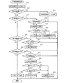
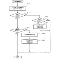
図10のステップS14において実行される可動体演出決定処理について図16を用いて説明する
最初に図16に示すように、メインCPU66は、ステップS131において、既に可動体80,96による演出が行われているか否かを判断し、演出中でなければステップS134へ処理を移す。そして、演出中と判断した場合は、ステップS132で可動体演出監視タイマがタイムアップ(つまり“0”)したか判断し、可動体演出監視タイマがタイムアップしていなかった場合は処理を終了する。また、可動体演出監視タイマがタイムアップしていた場合は、ステップS133において可動体演出終了処理を行う。この処理において、メインCPU66は、可動体演出の終了(停止)要求をメインRAM70の所定の領域に記憶して処理を終了する。
In addition, in the variation time of special symbols and normal symbols, as described above, the variation time in the probability variation mode or the short time mode is set short in the probability variation mode or the short time mode and the normal mode, and the normal symbol is hit. In this case, the opening time of the blade member 23 applied to the start port 25 is also set longer in the probability variation mode or the time reduction mode. Naturally, if the opening time of the blade member 23 is long, the chance that a game ball wins at the start port 25 increases as compared to the normal mode. Therefore, in the probability variation mode and the short time mode, the number of lotteries for special symbols per unit time increases. . Therefore, the lottery opportunities for expecting winning of the jackpot gaming state, which is the most advantageous gaming state for the player, increase. This is also an advantageous state for the player.
[Moving body production decision processing]
The movable body effect determination process executed in step S14 of FIG. 10 will be described with reference to FIG. 16. First, as shown in FIG. 16, the main CPU 66 has already performed effects by the movable bodies 80 and 96 in step S131. If it is determined that it is not presenting, the process proceeds to step S134. If it is determined that the effect is being performed, it is determined in step S132 whether the movable object effect monitoring timer has expired (that is, “0”). If the movable object effect monitoring timer has not expired, the process ends. . If the movable body effect monitoring timer has timed out, a movable body effect end process is performed in step S133. In this process, the main CPU 66 stores a movable body effect end (stop) request in a predetermined area of the main RAM 70 and ends the process.

ステップS134においては、メインCPU66は、特別図柄が変動中か否かを判断し、特別図柄が変動中でなければこの処理を終了する。一方、特別図柄が変動中であると判断した場合は、ステップS135において、メインCPU66は、特別図柄が大当たりに基いた図柄(当選図柄)か否かを判断し、当選図柄の場合は、ステップS136へ処理を移し、また当選していなかった場合は、ステップS139へ処理を移す。   In step S134, the main CPU 66 determines whether or not the special symbol is changing. If the special symbol is not changing, the main CPU 66 ends this processing. On the other hand, if it is determined that the special symbol is changing, in step S135, the main CPU 66 determines whether or not the special symbol is a symbol based on the jackpot (winning symbol), and if it is a winning symbol, step S136. If the process has not been won, the process proceeds to step S139.

ステップS136においては、メインCPU66は、図9(b)の可動体大当たり演出判定テーブルを参照し、対応する演出データを決定する。そしてステップS137において演出データの有無を判断し、演出データが無い場合(つまり“演出しない”が決定された場合)は処理を終了する。また、大当たり演出データが決定された場合は、メインCPU66は、ステップS138において、メインRAMの所定の領域に、決定された大当たり演出データや演出時間を監視する時間等を記憶して処理を終了する。   In step S136, the main CPU 66 refers to the movable body big hit effect determination table in FIG. 9B and determines the corresponding effect data. In step S137, the presence / absence of effect data is determined. If there is no effect data (that is, if “no effect” is determined), the process ends. If the jackpot effect data is determined, the main CPU 66 stores the determined jackpot effect data, the time for monitoring the effect time, and the like in a predetermined area of the main RAM in step S138 and ends the process. .

なお、図9(b)に示すように、前記可動体大当たり演出判定テーブルには、大当たり1、大当たり2・・・リーチ1、リーチ2の演出データの種類(演出なしを含む)と、各種類に割付けられた判定値が収められている。   As shown in FIG. 9B, in the movable body big hit effect determination table, the big hit 1, the big hit 2... Reach 1, reach 2 types of effect data (including no effect), and each type The judgment value assigned to is stored.

ステップS139においては、メインCPU66は、遊技状態の変化を判断し、遊技状態に変化がない場合は処理を終了する。そして、遊技状態に変化があった場合は、ステップS140において、図9(c)の可動体遊技状態演出判定テーブルを参照し、対応する演出データを決定して、ステップS141へ処理を移す。   In step S139, the main CPU 66 determines a change in the gaming state, and ends the process if there is no change in the gaming state. If there is a change in the game state, in step S140, the movable body game state effect determination table in FIG. 9C is referred to determine the corresponding effect data, and the process proceeds to step S141.

なお、図9(c)に示すように、可動体遊技状態演出判定テーブルには、各遊技状態(15R確変大当たり遊技状態、2R確変大当たり状態、15R通常大当たり状態、確変モード、時短モード)に応じた演出データの種類(演出なしを含む)と、各種類に割付けられた判定値が収められている。   As shown in FIG. 9C, the movable body game state effect determination table corresponds to each game state (15R probability variation big hit game state, 2R probability variation big hit state, 15R normal big hit state, probability variation mode, time reduction mode). The type of production data (including no production) and the judgment value assigned to each type are stored.

ステップS141においては、メインCPU66は、遊技状態演出データの有無を判断し、演出データが無い場合(つまり“演出しない”が決定された場合)は処理を終了する。そして、遊技状態演出データが決定された場合は、メインCPU66は、ステップS142において、メインRAMの所定の領域に、決定された遊技状態の演出データや演出時間を監視する時間等を記憶して処理を終了する。   In step S141, the main CPU 66 determines the presence / absence of game state effect data, and if there is no effect data (that is, if “no effect” is determined), the process ends. When the game state effect data is determined, the main CPU 66 stores and processes the determined game state effect data, the time for monitoring the effect time, and the like in a predetermined area of the main RAM in step S142. Exit.

この可動体演出決定処理で決定され、メインRAM70に記憶された、大当たり演出データ、遊技状態演出データおよび演出終了要求は、図11のシステムタイマ割込処理のコマンド出力処理(ステップS25)において、主制御回路60から副制御回路200へ送信される。そして、詳しくは後述するが、図17の副制御回路メイン処理の可動体制御処理(ステップS207)において、可動体による演出が実行される。
[副制御回路メイン処理]
一方、副制御回路200は、副制御回路メイン処理を実行することとなる。この副制御回路メイン処理について図17を用いて説明する。尚、この副制御回路メイン処理は、電源が投入されたときに開始される処理である。
The jackpot effect data, game state effect data, and effect end request determined in the movable body effect determination process and stored in the main RAM 70 are the main output in the command output process (step S25) of the system timer interruption process in FIG. It is transmitted from the control circuit 60 to the sub-control circuit 200. As will be described in detail later, in the movable body control process (step S207) of the sub-control circuit main process of FIG. 17, the effect by the movable body is executed.
[Sub control circuit main processing]
On the other hand, the sub-control circuit 200 executes the sub-control circuit main process. The sub control circuit main process will be described with reference to FIG. The sub-control circuit main process is a process that starts when the power is turned on.

最初に、図17に示すように、サブCPU206は、RAMアクセス許可、作業領域を初期化等の初期設定処理を実行する(ステップS201)。つまり、サブCPU206は、電源が投入されたことに基づいて、遊技を正常に行わせるための所定の初期設定を行うこととなる。尚、本実施形態においては、ステップS201を実行するサブCPU206は、初期設定手段の一例に相当する。この処理が終了した場合には、ステップS202に処理を移す。   First, as shown in FIG. 17, the sub CPU 206 executes an initial setting process such as RAM access permission and work area initialization (step S201). That is, the sub CPU 206 performs a predetermined initial setting for normally playing the game based on the power being turned on. In the present embodiment, the sub CPU 206 that executes step S201 corresponds to an example of an initial setting unit. If this process ends, the process moves to a step S202.

ステップS202において、サブCPU206は、乱数更新処理を実行する。この処理において、サブCPU206は、ワークRAM210の所定領域に位置付けられた各種の乱数カウンタの乱数値を更新する。この処理が終了した場合には、ステップS203に処理を移す。   In step S202, the sub CPU 206 executes random number update processing. In this process, the sub CPU 206 updates random number values of various random number counters positioned in a predetermined area of the work RAM 210. If this process ends, the process moves to a step S203.

ステップS203において、サブCPU206は、受信したコマンドを解析し、その解析したコマンドに応じた処理を実行することとなる。この処理が終了した場合には、ステップS204に処理を移す。   In step S203, the sub CPU 206 analyzes the received command and executes a process corresponding to the analyzed command. If this process ends, the process moves to a step S204.

ステップS204において、サブCPU206は、液晶表示装置32における画像の表示制御を行う。   In step S <b> 204, the sub CPU 206 performs image display control on the liquid crystal display device 32.

そして、サブCPU206は、スピーカ46から発生させる音の制御を行う音声制御処理(ステップS205)、各種のランプ133a、133bの発光制御を行うランプ制御処理を実行する(ステップS206)。この処理が終了した場合には、ステップS207に処理を移す。   Then, the sub CPU 206 executes a sound control process for controlling sound generated from the speaker 46 (step S205) and a lamp control process for controlling light emission of the various lamps 133a and 133b (step S206). If this process ends, the process moves to a step S207.

ステップS207において、サブCPU206は、遊技機本体から回転しながら又は直線的に出没する可動体80,96の演出データの制御を行う(詳細は図18を用いて後述する)。この処理が終了した場合には、ステップS202に処理を移す。   In step S207, the sub CPU 206 controls the effect data of the movable bodies 80 and 96 that appear or disappear linearly while rotating from the gaming machine main body (details will be described later with reference to FIG. 18). If this process ends, the process moves to a step S202.

このように、副制御回路メイン処理においては、ステップS201の初期設定処理が終了した後、ステップS202からステップS207の処理を繰り返し実行することとなる。
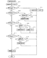
[可動体制御処理]
図17のステップS207において実行される可動体制御処理について図18を用いて説明する。
As described above, in the sub control circuit main process, after the initial setting process in step S201 is completed, the processes from step S202 to step S207 are repeatedly executed.
[Moving object control processing]
The movable body control process executed in step S207 in FIG. 17 will be described with reference to FIG.

最初に、サブCPU206は、ステップS211において、図17の副制御回路メイン処理のコマンド解析処理(ステップS203)で受信した主制御回路60からの、可動体演出コマンドを判定し、ワークRAM210の所定の領域に記憶する。そしてステップS212へ処理を移す。   First, in step S211, the sub CPU 206 determines the movable body effect command from the main control circuit 60 received in the command analysis process (step S203) of the sub control circuit main process in FIG. Store in the area. Then, the process proceeds to step S212.

ステップS212において、サブCPU206は、可動体80、96による演出が実行中であるか判断し、演出中でない場合はステップS215へ処理を移す。そして演出中の場合は、ステップS213で、主制御回路60からの可動体演出コマンドが、演出終了要求か判断し、演出終了要求でない場合は処理を終了する。一方、演出終了要求であった場合には、サブCPU206は、ステップS214において、可動体制御回路260に対し演出の停止(つまり送風停止及び可動体80,96の後退)を指示して処理を終了する。   In step S212, the sub CPU 206 determines whether or not an effect by the movable bodies 80 and 96 is being executed. If not, the process proceeds to step S215. If the effect is in progress, it is determined in step S213 whether the movable body effect command from the main control circuit 60 is an effect end request, and if it is not an effect end request, the process ends. On the other hand, if it is an effect end request, the sub CPU 206 instructs the movable body control circuit 260 to stop the effect (that is, stop the blowing and move the movable bodies 80 and 96 backward) in step S214 and end the processing. To do.

ステップS215において、サブCPU206は、主制御回路60からの可動体演出コマンドをチェックし、可動体80による演出指示の有無を判断する。そして演出指示がなかった場合は処理を終了し、演出指示があった場合は、サブCPU206は、ステップS216において、プログラムROM208にあらかじめ登録されている複数の演出表示パターンから、可動体演出コマンドで指定された演出用の可動体駆動態様及び送風態様からなる可動体演出態様を決定し、ステップS217へ処理を移す。   In step S <b> 215, the sub CPU 206 checks the movable body effect command from the main control circuit 60, and determines whether there is an effect instruction from the movable body 80. If there is no production instruction, the process ends. If there is an production instruction, the sub CPU 206 designates a movable body production command from a plurality of production display patterns registered in advance in the program ROM 208 in step S216. The movable body effect aspect which consists of the movable body drive aspect and the ventilation | gas_flowing aspect for the produced effect is determined, and a process is moved to step S217.

ステップS217において、サブCPU206は、ステップS216で決定された、可動体演出データを可動体制御回路260に指示することにより、回動モータ及び送風手段による、可動体80,96による演出が開始されることとなる。この後、サブCPU206は可動体制御処理を終了する。   In step S217, the sub CPU 206 instructs the movable body effect data determined in step S216 to the movable body control circuit 260, so that the effects by the movable bodies 80 and 96 by the rotation motor and the air blowing means are started. It will be. Thereafter, the sub CPU 206 ends the movable body control process.

このように、遊技機における演出表示を、遊技機本体の外部に突出する可動体に風が吹き付けられ、この風によってより動作が変化するという、これまでにない大きなインパクトのある斬新な演出をなすことができ、遊技者の遊技に対する興趣を著しく高めることができる。しかも、この可動体80,96による演出は、大当たりの抽選結果や遊技状態の変化に応じて制御されるので単調にならず変化に富むものとなり、意外性があり、かつ新鮮味のある演出表示として遊技者の興味をさらに引くことが可能となる
また、本実施形態においては、パチンコ遊技機等の遊技機自体に本発明を適用したが、パチスロ遊技機やその他各種ゲーム機などに適用してもよい。
In this way, the effect display in the gaming machine is a novel effect with an unprecedented great impact that the wind is blown to the movable body protruding outside the gaming machine main body, and the operation is changed by this wind. And the interest of the player in the game can be significantly enhanced. Moreover, the production by the movable bodies 80 and 96 is controlled according to the jackpot lottery result and the change in the gaming state, so it is not monotonous and rich in change, and is an unexpected and fresh production display. Further, in this embodiment, the present invention is applied to a gaming machine itself such as a pachinko gaming machine. However, the present invention may be applied to a pachislot gaming machine or other various gaming machines. Good.

以上、本発明を実施形態を通して説明したが、本実施形態では具体例を例示したに過ぎず、特に本発明を限定するものではない。すなわち、本発明は、主に、遊技者にとって有利なラウンドゲームを複数回行う有利な遊技を実行するか否かの抽選を制御するとともに、当該有利な遊技の実行の制御を行う制御手段と、前記有利な遊技の実行時に所定の開放動作を行う役物が備えられた遊技盤と、演出画像を表示する表示手段と、前記表示手段における演出画像の表示制御を行う表示制御手段と、特に演出手段として可動体と、それを制御する可動体制御手段を備えることを特徴とする遊技機であるが、制御手段、遊技盤などの具体的構成は、適宜設計変更可能である。   As mentioned above, although this invention was demonstrated through embodiment, this embodiment only illustrated the specific example and does not limit this invention in particular. That is, the present invention mainly controls a lottery to determine whether or not to execute an advantageous game in which a round game advantageous to the player is performed a plurality of times, and also controls the execution of the advantageous game; A gaming board provided with an accessory that performs a predetermined opening operation at the time of execution of the advantageous game, display means for displaying effect images, display control means for controlling display of effect images on the display means, and particularly effects Although the game machine is characterized by comprising a movable body as means and a movable body control means for controlling the movable body, the specific configuration of the control means, the game board, and the like can be changed as appropriate.

尚、本発明の実施形態に記載された効果は、本発明から生じる最も好適な効果を列挙したに過ぎず、本発明による効果は、本発明の実施形態に記載されたものに限定されるものではない。   It should be noted that the effects described in the embodiments of the present invention only list the most preferable effects resulting from the present invention, and the effects of the present invention are limited to those described in the embodiments of the present invention. is not.

本発明の一実施形態のパチンコ遊技機における概観を示す斜視図である。1 is a perspective view showing an overview of a pachinko gaming machine according to an embodiment of the present invention. 本発明の一実施形態のパチンコ遊技機における概観を示す分解斜視図である。It is a disassembled perspective view which shows the general view in the pachinko game machine of one Embodiment of this invention. 本発明の一実施形態のパチンコ遊技機において構成される電飾ユニットを示す正面図である。It is a front view which shows the electrical decoration unit comprised in the pachinko game machine of one Embodiment of this invention. 本発明の一実施形態のパチンコ遊技機における概観を示す正面図である。It is a front view which shows the general view in the pachinko game machine of one Embodiment of this invention. 本発明の一実施形態のパチンコ遊技機の一側及び他側にそれぞれ配設される可動体及び吸気口の一例を示す断面側面図である。1 is a cross-sectional side view showing an example of a movable body and an air inlet that are respectively disposed on one side and the other side of a pachinko gaming machine according to an embodiment of the present invention. 本発明の他の実施形態のパチンコ遊技機における概観を示す斜視図である。It is a perspective view which shows the general view in the pachinko game machine of other embodiment of this invention. 本発明のー実施形態のパチンコ遊技機における遊技島の平面図である。1 is a plan view of a game island in a pachinko gaming machine according to an embodiment of the present invention. FIG. 本発明の一実施形態のパチンコ遊技機において構成される主制御回路及び副制御回路を示すブロック図である。It is a block diagram which shows the main control circuit and sub control circuit which are comprised in the pachinko game machine of one Embodiment of this invention. 本発明の一実施形態のパチンコ遊技機において参照される各種判定テーブルである。It is various determination tables referred in the pachinko gaming machine of one embodiment of the present invention. 本発明の一実施形態のパチンコ遊技機において実行される制御処理を示すフローチャートである。It is a flowchart which shows the control processing performed in the pachinko game machine of one Embodiment of this invention. 本発明の一実施形態のパチンコ遊技機において実行される制御処理を示すフローチャートである。It is a flowchart which shows the control processing performed in the pachinko game machine of one Embodiment of this invention. 本発明の一実施形態のパチンコ遊技機において実行される制御処理を示すフローチャートである。It is a flowchart which shows the control processing performed in the pachinko game machine of one Embodiment of this invention. 本発明の一実施形態のパチンコ遊技機において実行される制御処理を示すフローチャートである。It is a flowchart which shows the control processing performed in the pachinko game machine of one Embodiment of this invention. 本発明の一実施形態のパチンコ遊技機において実行される制御処理を示すフローチャートである。It is a flowchart which shows the control processing performed in the pachinko game machine of one Embodiment of this invention. 本発明の一実施形態のパチンコ遊技機において実行される制御処理を示すフローチャートである。It is a flowchart which shows the control processing performed in the pachinko game machine of one Embodiment of this invention. 本発明の一実施形態のパチンコ遊技機において実行される制御処理を示すフローチャートである。It is a flowchart which shows the control processing performed in the pachinko game machine of one Embodiment of this invention. 本発明の一実施形態のパチンコ遊技機において実行される制御処理を示すフローチャートである。It is a flowchart which shows the control processing performed in the pachinko game machine of one Embodiment of this invention. 本発明の一実施形態のパチンコ遊技機において実行される制御処理を示すフローチャートである。It is a flowchart which shows the control processing performed in the pachinko game machine of one Embodiment of this invention.

符号の説明Explanation of symbols

10 パチンコ遊技機
14 遊技盤
32 液晶表示装置
60 主制御回路
80 可動体
96 可動体
200 副制御回路
260 可動体制御回路
DESCRIPTION OF SYMBOLS 10 Pachinko machine 14 Game board 32 Liquid crystal display device 60 Main control circuit 80 Movable body 96 Movable body 200 Sub control circuit 260 Movable body control circuit

Claims (5)

遊技領域を前方側に設けた遊技機本体と、
この遊技機本体の内部に、当該遊技機本体の前方側より当該遊技本体外方へ出没自在に収納された可動体と、
この可動体に向けて送風する送風手段と、
前記可動体を遊技機本体外方に突出させるとともに、この可動体に前記送風手段から風を吹き付けて可動態様に変化を与える演出制御を実行する演出制御手段と、
を備えることを特徴とする遊技機。
A gaming machine main body provided with a gaming area on the front side;
Inside the gaming machine body, a movable body housed in a manner that allows the game machine body to be moved in and out from the front side of the gaming machine body,
A blowing means for blowing air toward the movable body;
Production control means for causing the movable body to protrude outward from the gaming machine main body and performing production control for changing the movable mode by blowing wind from the blowing means to the movable body;
A gaming machine comprising:
前記演出制御手段は、遊技状態の変化に応じて、前記可動体に対する風の吹き付け角度を変化させることを特徴とする請求項1に記載の遊技機。   The gaming machine according to claim 1, wherein the effect control unit changes a wind blowing angle with respect to the movable body according to a change in a gaming state. 前記演出制御手段は、遊技状態の変化に応じて、前記可動体に対する風の吹き付け強度を変化させることを特徴とする請求項1又は2に記載の遊技機。   The gaming machine according to claim 1 or 2, wherein the effect control means changes a wind blowing strength to the movable body according to a change in a gaming state. 前記可動体を複数種類設け、前記演出制御手段は、変化した遊技状態に応じて、各前記可動体に吹き付ける風の吹き付け角度及び/又は吹き付け強度を変化させることを特徴とする請求項1に記載の遊技機。   The plurality of types of the movable bodies are provided, and the effect control unit changes a blowing angle and / or a blowing strength of the wind sprayed on each movable body according to a changed gaming state. Game machines. 請求項1〜5のいずれか1項に記載の遊技機が、当該遊技機における前記遊技機本体の幅方向に複数台並設してなる設備本体を、各遊技機本体の後方側が所定空間を介して向かい合うように2列配置した遊技設備であって、
前記各遊技機に設けられた前記送風手段は、各前記遊技機本体の後方側における前記所定空間内の空気を、各前記遊技機本体の前方側に突出された前記可動体に向けて吹き付けることを特徴とする遊技設備。
The gaming machine according to any one of claims 1 to 5, wherein a plurality of equipment bodies are arranged in parallel in the width direction of the gaming machine body in the gaming machine, and a rear side of each gaming machine body has a predetermined space. Game equipment arranged in two rows so as to face each other,
The air blowing means provided in each gaming machine blows air in the predetermined space on the rear side of each gaming machine body toward the movable body projecting to the front side of each gaming machine body. A game facility characterized by
JP2006115282A 2006-04-19 2006-04-19 Game machine and game equipment Pending JP2007282948A (en)

Priority Applications (1)

Application Number Priority Date Filing Date Title
JP2006115282A JP2007282948A (en) 2006-04-19 2006-04-19 Game machine and game equipment

Applications Claiming Priority (1)

Application Number Priority Date Filing Date Title
JP2006115282A JP2007282948A (en) 2006-04-19 2006-04-19 Game machine and game equipment

Publications (1)

Publication Number Publication Date
JP2007282948A true JP2007282948A (en) 2007-11-01

Family

ID=38755245

Family Applications (1)

Application Number Title Priority Date Filing Date
JP2006115282A Pending JP2007282948A (en) 2006-04-19 2006-04-19 Game machine and game equipment

Country Status (1)

Country Link
JP (1) JP2007282948A (en)

Cited By (1)

* Cited by examiner, † Cited by third party
Publication number Priority date Publication date Assignee Title
JP2014061083A (en) * 2012-09-20 2014-04-10 Newgin Co Ltd Game machine

Cited By (1)

* Cited by examiner, † Cited by third party
Publication number Priority date Publication date Assignee Title
JP2014061083A (en) * 2012-09-20 2014-04-10 Newgin Co Ltd Game machine

Similar Documents

Publication Publication Date Title
JP2008029603A (en) Game machine
JP2007275432A (en) Pinball game machine
JP2008061749A (en) Game machine
JP2008132178A (en) Game machine
JP2008119383A (en) Game machine
JP2009106554A (en) Game machine
JP2008110035A (en) Game machine
JP2008104582A (en) Game machine
JP2008029602A (en) Game machine
JP2008206713A (en) Game machine
JP2007282947A (en) Game machine
JP2008132181A (en) Game machine
JP2009148413A (en) Game machine
JP2009072464A (en) Game machine
JP2008132175A (en) Game machine
JP2007319194A (en) Game machine and game equipment
JP2007259897A (en) Game machine
JP2006314377A (en) Game machine
JP2007282948A (en) Game machine and game equipment
JP2008132177A (en) Game machine
JP2007202983A (en) Game machine
JP2009106561A (en) Game machine
JP2008302021A (en) Game machine
JP2008061750A (en) Game machine
JP2008183198A (en) Game machine