JP2007237242A - Laser beam machining apparatus - Google Patents
Laser beam machining apparatus Download PDFInfo
- Publication number
- JP2007237242A JP2007237242A JP2006063484A JP2006063484A JP2007237242A JP 2007237242 A JP2007237242 A JP 2007237242A JP 2006063484 A JP2006063484 A JP 2006063484A JP 2006063484 A JP2006063484 A JP 2006063484A JP 2007237242 A JP2007237242 A JP 2007237242A
- Authority
- JP
- Japan
- Prior art keywords
- laser
- processing
- trepanning
- mask
- processing apparatus
- Prior art date
- Legal status (The legal status is an assumption and is not a legal conclusion. Google has not performed a legal analysis and makes no representation as to the accuracy of the status listed.)
- Withdrawn
Links
Images


Abstract
Description
本発明はレーザ光を用いて穴の加工や、切断等を行うレーザ加工方法およびレーザ加工装置に係り、特に、プリント配線基板にビアホールを加工するのに好適なレーザ加工装置に関する。 The present invention relates to a laser processing method and a laser processing apparatus for processing or cutting holes using laser light, and more particularly to a laser processing apparatus suitable for processing a via hole in a printed wiring board.
以下、従来のレーザ加工装置について説明する。 Hereinafter, a conventional laser processing apparatus will be described.
電子機器の小型化,高密度実装化に伴い、プリント配線基板は複数の基板を積層した多層配線基板が主流となっている。多層配線基板では、上下に積層された基板間の導電層を電気的に接続する必要がある。そこで、多層配線基板の絶縁層に下層の導電層に達するビアホール(穴)を形成し、ビアホールの内部に導電性メッキを施すことにより、上下に積層された基板間の導電層を電気的に接続している。 Along with the downsizing and high-density mounting of electronic devices, printed wiring boards are mainly multilayer wiring boards in which a plurality of boards are stacked. In a multilayer wiring board, it is necessary to electrically connect conductive layers between substrates stacked one above the other. Therefore, a via hole (hole) reaching the lower conductive layer is formed in the insulating layer of the multilayer wiring board, and conductive plating is applied to the inside of the via hole to electrically connect the conductive layers between the substrates stacked vertically. is doing.
ビアホールの形成には、ビアホールの微細化に伴い、高出力のCO2 レーザやYAGの高調波を利用したUVレーザが使用される。また、ガルバノミラーとfθレンズを組み合せたビームスキャン光学系を用いて、レーザ光を走査させることにより高速加工を実現している。さらに、加工する穴径を選択するためマスクとしてアパーチャを採用し、その像を結像レンズ用いて基板上に転写する結像光学系を採用し、また、1つのビアホールに対してレーザ光を複数回に分けて照射することにより、ビアホールの形状品質を向上させている。 For the formation of the via hole, a high-power CO 2 laser or a UV laser using a harmonic of YAG is used with the miniaturization of the via hole. Further, high-speed processing is realized by scanning a laser beam using a beam scanning optical system in which a galvano mirror and an fθ lens are combined. Furthermore, an aperture is used as a mask to select the hole diameter to be processed, an imaging optical system is used to transfer the image onto the substrate using an imaging lens, and a plurality of laser beams are emitted to one via hole. By irradiating in divided times, the shape quality of the via hole is improved.
しかしながら、プリント基板製造における穴あけ加工に対するスループット向上の要求は高密度化による穴数の増加に伴い、益々厳しくなってきている。また、穴径の小径化に伴い位置精度に対する要求も同様に厳しくなってきている。 However, the demand for improving throughput for drilling in printed circuit board manufacturing has become increasingly severe as the number of holes has increased due to higher density. In addition, as the hole diameter is reduced, the requirements for positional accuracy are becoming stricter as well.
以上のような加工スループットの向上に対する要求に応えるため、加工ビームをマルチ化したレーザ加工装置が複数提案されている。マルチ化の方法としてはレーザ光を時間的に切替えて行うレーザ加工装置(例えば、特許文献1)やレーザ光を空間的に分割して行うレーザ加工装置(例えば、特許文献2)が代表的である。 In order to meet the demands for improving the processing throughput as described above, a plurality of laser processing apparatuses having multiple processing beams have been proposed. As a method of multi-sizing, a laser processing apparatus (for example, Patent Document 1) that switches laser light temporally and a laser processing apparatus (for example, Patent Document 2) that splits laser light spatially are typical. is there.
レーザ加工にはレーザ光のビームスポット径が、ほぼビアホールの穴径となるパンチ加工の他に、穴の軌跡を描きながらレーザ照射することでビームスポット径より大きい穴径のビアホールを加工するトレパニング加工がある。特にトレパニング加工は小径加工を得意とするUVレーザ加工機で、大きな穴径のビアホールを加工する際に必須の技術となっている。トレパニング加工では、加工軌跡をパンチ加工で高速位置決めに使用しているガルバノスキャナを用いて描くことが多い。パンチ加工ではある位置から他の位置へ急速に移動させるステップ走査で2点間を移動する道程での挙動が重要視されない。これに対して、トレパニング加工では軌跡を描くため移動中の道程の挙動も重要となり、高い追従性が要求される。しかし、高速動作でパンチ加工の高精度位置決めと、トレパニング加工の高い追従性を両立させることは困難である。特許文献1および特許文献2に記載のレーザ加工装置は共に、トレパニング加工に関しては配慮されておらず、小径から太径まで多様化するビアホール加工に十分対応できないという問題があった。
For laser processing, in addition to punching, where the beam spot diameter of the laser beam is approximately the diameter of the via hole, trepanning processing that processes a via hole with a diameter larger than the beam spot diameter by irradiating the laser while drawing the locus of the hole. There is. In particular, trepanning is a UV laser processing machine that excels at small-diameter processing, and has become an indispensable technique when processing via holes with large hole diameters. In trepanning processing, the processing locus is often drawn using a galvano scanner which is used for high-speed positioning by punching. In punching, the behavior along the path of moving between two points in step scanning that rapidly moves from one position to another is not regarded as important. On the other hand, in the trepanning process, since the trajectory is drawn, the behavior of the traveling route is also important, and high followability is required. However, it is difficult to achieve both high-precision positioning of punching and high followability of trepanning at high speed. Both the laser processing apparatuses described in
本発明の目的は、上記した課題を解決してパンチ加工とトレパニング加工共に高精度位置決めと高追従性を両立させるレーザ加工装置およびその方法を提供することにある。 An object of the present invention is to provide a laser processing apparatus and method for solving the above-described problems and achieving both high precision positioning and high followability in both punching and trepanning.
上記課題を解決するために、本発明のレーザ加工装置はプリント基板上の所定の加工位置に対して位置決め動作を行うスキャナと、1つのビアホールの外形を描くトレパニング動作を行うスキャナを別々に設けることを特徴とする。 In order to solve the above-described problems, the laser processing apparatus of the present invention separately provides a scanner that performs a positioning operation with respect to a predetermined processing position on a printed circuit board and a scanner that performs a trepanning operation for drawing the outline of one via hole. It is characterized by.
説明した本発明のレーザ加工装置によれば、パンチ加工とトレパニング加工の双方において、加工スループットと穴形状の向上を図ることが可能となり、小径から太径まで多様な穴加工が可能となる。 According to the described laser processing apparatus of the present invention, it is possible to improve processing throughput and hole shape in both punching and trepanning processing, and various hole processing from a small diameter to a large diameter is possible.
以下、図面を用いて本発明の実施例について説明する。 Embodiments of the present invention will be described below with reference to the drawings.
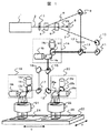
図1は、本発明の第1の実施例である、1つの発光源からの光を用いて2枚の基板を時分割で加工できるレーザ加工装置の構成図である。初めに、レーザ光の光路について説明する。 FIG. 1 is a configuration diagram of a laser processing apparatus according to a first embodiment of the present invention that can process two substrates in a time-sharing manner using light from one light emitting source. First, the optical path of laser light will be described.
レーザ発振器1から出射されたレーザ光2は、ビーム径(加工形状)を決定するマスク3を介してビーム分配整形器4,5に入射する。ビーム分配整形器4,5は、レーザ加工機の上位制御装置(図示せず)の指令によりレーザ光2の方向を切替える機能と、パルス波形を矩形状に整形する機能とを有する。ビーム分配整形器4がON状態ではレーザ光2は第1の加工ビーム6として進行方向を変え固定ミラー9に入射し、OFF状態ではそのまま直進してビーム分配整形器5に至る。ビーム分配整形器5に入射したレーザ光2は、ビーム分配整形器5がON状態で第2の加工ビーム7として進行方向を変え固定ミラー
10に入射し、OFF状態ではそのまま直進して遮光体8に至る。従って、ビーム分配整形器4,5のON/OFFを切替えることで、第1の加工ビーム6と第2の加工ビーム7とを時分割で切替えることができる。まず、第1の加工ビーム6の光路について述べる。
The
ビーム分配整形器4をON状態として出射された第1の加工ビーム6は、固定ミラー9で反射され、1/2波長板12を介して第1の偏光ビームスプリッタ13で反射され、第1の2軸スキャナ14に入射する。この第1の2軸スキャナ14はパンチ加工時には固定ミラーとして、トレパニング加工時にはトレパニング軌跡生成スキャナとして機能する。第1の2軸スキャナ14を出射した第1の加工ビーム6は第2の偏光ビームスプリッタ
15で反射して、固定ミラー16,17を介して第2の2軸スキャナ19に入射する。第2の2軸スキャナ19によってfθレンズ21へ入射する角度が制御されてXYステージ23上に設置された基板24の所定の位置に照射する(加工エリア50×50mm角程度)。
The first processed
次に、第2の加工ビーム7の光路について述べる。OFF状態のビーム分配整形器4を直進してON状態の分配整形器5により方向を変えられた第2の加工ビーム7は、固定ミラー10,11を介して第1の偏光ビームスプリッタ13を透過することで、第1の加工ビーム6と重畳(合成)されて第1の2軸スキャナ14に入射する。第1の2軸スキャナ14を出射した第2の加工ビーム7は第2の偏光ビームスプリッタ15を透過することで、第1の加工ビーム6と分離され、固定ミラー18に入射される。固定ミラー18で反射された第2の加工ビーム7は第3の2軸スキャナ20でfθレンズ22へ入射する角度が制御されてXYステージ23上に設置された基板25の所定の位置に照射する(加工エリア50×50mm角程度)。
Next, the optical path of the second machining beam 7 will be described. The second processed beam 7 that has traveled straight through the OFF beam distribution /
ここで、第1の2軸スキャナ14は、合成されたビームをXYステージ23に載置された基板面上でX軸方向に振るためのミラー14aが取り付けられたガルバノスキャナ14bと、Y軸方向に振るためのミラー14cが取り付けられたガルバノスキャナ14dとから構成されている。
Here, the first
第2の2軸スキャナ19は、第1の加工ビーム6をXYステージ23上における基板
24面上の被加工領域に対してX軸方向に振るためのミラー19aが取り付けられたガルバノスキャナ19bと、Y軸方向に振るためのミラー19cが取り付けられたガルバノスキャナ19dとから構成されている。同様に、第3の2軸スキャナ20は、第2の加工ビーム7をXYステージ23上における基板25面上の被加工領域に対してX軸方向に振るためのミラー20aが取り付けられたガルバノスキャナ20bと、Y軸方向に振るためのミラー20cが取り付けられたガルバノスキャナ20dとから構成されている。
The second
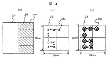
XYステージ23は、図示していない駆動機構によりXY方向に移動可能に構成されている。このXYステージに搭載された基板(例えば基板24)は、図4(a)に示すように、第2の2軸スキャナ19による被加工領域26での加工が終了すると、次の被加工領域27が来るように移動させて位置決めする。なお、第3の2軸スキャナ20と基板25の関係も被加工領域は図4(a)と同じである。
The
次に、第1の偏光ビームスプリッタ13,第2の偏光ビームスプリッタ15の機能について述べる。偏光ビームスプリッタはP偏光(振動方向が紙面に対して平行な光)を透過させて、S偏光(振動方向が紙面に対して垂直な光)を反射する特性を有している。いま、レーザ発振器1から出射されるレーザ光2がP偏光とすると、第2の加工ビーム7はP偏光のままなので、第1の偏光ビームスプリッタ13を100%透過する。一方、第1の加工ビーム6は1/2波長板12でS偏光に変換されるので第1の偏光ビームスプリッタ13で100%反射される。従って、第1の加工ビーム6がS偏光、第2の加工ビーム7がP偏光になるので第1偏光ビームスプリッタ13を使って別な光路を経由してきた2つの光の光路をロスなく同軸にすることができる。したがって、第1の加工ビーム6と第2の加工ビーム7は、第1の2軸スキャナ14で同じ軌跡を描き、第2の偏向ビームスプリッタ15へ入射する。第1の加工ビーム6と第2の加工ビームは第1の2軸スキャナ14を出射後もそれぞれ偏向状態が保たれているので、第2の偏光ビームスプリッタ15へ入射したS偏光の第1の加工ビーム6は100%反射、P偏光の第2の加工ビーム7は100%透過する。
Next, functions of the first polarizing
次に、本発明のレーザ加工装置の動作について説明する。 Next, the operation of the laser processing apparatus of the present invention will be described.
まず、パンチ加工について述べる。パンチ加工では第1の2軸スキャナ14は中心位置で固定して、固定ミラーとして機能させる。レーザ発振器1はレーザ光2の光強度およびビームプロファイルの安定化を図るため、常時同じ繰返し周波数でパルス発振させておく。いま、ビーム分配整形器4を上位制御装置(図示せず)の指令により、所定の時間だけONさせて第1の加工ビーム6を選択し、基板24に対して所定のレーザパルス数を照射してパンチ加工を行う。
First, punching will be described. In punching, the first two-
このとき、ビーム分配整形器5はOFFにしておき、同時に第3の2軸スキャナ20を動作させ基板25の任意の加工位置へ第2の加工ビーム7を照射できるように、位置決め動作を完了しておく。次に、ビーム分配整形器4をOFFとし、ビーム分配整形器5を
ONさせて加工ビーム7を選択すると、すでに基板25の任意の位置に対して、位置決めが完了しているので、すぐに所定のレーザパルス数を照射してパンチ加工を行うことができる。このとき、第2の2軸スキャナ19は次の加工位置へ第1の加工ビーム6を照射できるように、位置決め動作を完了しておく。以上の動作を図4(b)に示すように第2の2軸スキャナ19および第3の2軸スキャナ20の加工エリア26(50×50mm角程度)内で、穴位置の座標が記述してある加工プログラムに従い、例えば図4(b)に矢印で示した順序でレーザ光2の100%の加工エネルギーで基板24、25それぞれに対してパンチ加工28aができる。なお、第2の2軸スキャナ19および第3の2軸スキャナ20が基板の所定の加工エリアでの加工が終了して、次の被加工領域へ基板面を移動させるためXYステージ23が動作している間は、ビーム分配整形器4,5は共にOFFにしておく。このため、レーザ光2はビーム分配整形器4,5をほぼ100%透過して遮光ビーム29として遮光体8で吸収することで熱に変換されるので、加工ビームは基板へ照射されることはない。
At this time, the beam distribution /
次に、トレパニング加工について述べるが、パンチ加工と異なるのは第1の2軸スキャナ14の機能であり、その他の動作はパンチ加工と同じなので説明は省略する。トレパニング加工において第1の2軸スキャナ14は任意のトレパニング軌跡を常時繰返し描き続ける。例えば、図6(a)に示すようにガルバノスキャナ14aと14cを同じ振幅で位相をπ/2radだけずらして走査することで、図6(b)に示すように円軌跡を生成することができる。そして、ビーム分配整形器4,5は基板24,25に対してトレパニング加工が完了する所定の時間だけそれぞれON状態にすれば、図4(c)に示すような例えば、穴位置の座標が記述してある加工プログラムに従い、図4(c)に矢印で示した順序でレーザ光2の100%の加工エネルギーで基板24,25それぞれに対してトレパニング加工28bを行うことができる。
Next, the trepanning process will be described. The difference from the punching process is the function of the first
以上、説明したように本発明のレーザ加工装置によれば、トレパニング加工の軌跡を描くスキャナを別途配置することで、パンチ加工とトレパニング加工の双方において、加工スループットと穴形状の向上を図ることが可能となり、小径から太径まで多様な穴加工が可能となる。 As described above, according to the laser processing apparatus of the present invention, by separately arranging a scanner that draws a trace of trepanning, it is possible to improve processing throughput and hole shape in both punching and trepanning. This makes it possible to drill various holes from small to large diameters.
次に、本発明の第2の実施例を説明する。図2は本発明による第2の実施例であるレーザ加工装置の構成を示す構成図である。まず、第2の実施例の構成要素について述べるが、図2において図1と共通のものは同じ符号を用いたので説明は省略する。ここで、新たに追加修正された構成要素は、ビーム分配整形器5を削除し、第1の偏光ビームスプリッタの代わりにビームスプリッタ30を用いる点のみである。
Next, a second embodiment of the present invention will be described. FIG. 2 is a block diagram showing the configuration of the laser machining apparatus according to the second embodiment of the present invention. First, the components of the second embodiment will be described. In FIG. 2, the same components as those in FIG. Here, the only newly added and modified component is that the
初めに、レーザ光の光路について説明する。 First, the optical path of laser light will be described.
レーザ光2はレーザ発振器1から出射され、マスク3を介してビーム分配整形器4に入射する。ビーム分配整形器4はレーザ加工機の上位制御装置(図示せず)の指令によりレーザ光2の方向を切替える機能とパルス波形を矩形状に整形する機能とを有する。ビーム分配整形器4がON状態ではレーザ光2は進行方向を変え、OFF状態ではそのまま直進して遮光体8に至る。
The
レーザ光2は固定ミラー9,10を介して、第1の2軸スキャナ14に入射する。第1の2軸スキャナ14はパンチ加工時には固定ミラー、トレパニング加工時にはトレパニング軌跡生成スキャナとして機能する。第1の2軸スキャナ14を出射したレーザ光2はビームスプリッタ30で加工エネルギーが50%ずつ第1の加工ビーム6と第2の加工ビーム7に分割される。これ以後の第1の加工ビーム6と第2の加工ビーム7の光路は実施例1と同じなので省略する。
The
次に、本発明における第2の実施例の動作を詳細に述べるが、まず、パンチ加工について述べる。パンチ加工では第1の2軸スキャナ14は中心位置で固定して、固定ミラーとして機能させる。レーザ発振器1はレーザ光2の光強度およびビームプロファイルの安定化を図るため、常時同じ繰返し周波数でパルス発振させておく。いま、ビーム分配整形器4を上位制御装置(図示せず)の指令により、所定の時間だけONさせてレーザ光2をビームスプリッタ30で2分割し、その2分割された加工ビームのうち第1の加工ビーム6を基板24、第2の加工ビーム7を基板25に、同時に所定のレーザパルス数だけ照射する。このとき、例えば穴位置の座標を記述してある加工プログラムに従い、図4(b)に矢印で示した順序でレーザ光2を照射することで50%の加工エネルギーで基板24,
25それぞれに対してパンチ加工28aができる。
Next, the operation of the second embodiment of the present invention will be described in detail. First, punching will be described. In punching, the first two-
なお、XYステージ23が動作している間は、ビーム分配整形器4はOFFにしておけば、レーザ光2はビーム分配整形器4をほぼ100%透過して遮光ビーム29として遮光体8で吸収することで熱に変換されるので、加工ビームが基板へ照射されることはない。
While the
次に、トレパニング加工について述べるが、パンチ加工と異なるのは第1の2軸スキャナ14が任意のトレパニング軌跡を常時繰返し描き続けることだけであり、その他の動作はパンチ加工と同じなので説明は省略する。
Next, the trepanning process will be described. The only difference from the punching process is that the first
次に、本発明の第3の実施例を説明する。図3は本発明による第3の実施例であるレーザ加工装置の構成を示す構成図である。前述までの実施例は2つの基板を加工する構成であったが、本実施例では1つの基板上に同時に2箇所のパンチ加工又は2箇所のトレパニング加工を行う構成のものである。まず、第3の実施例の構成要素について述べるが、図3において図1と共通のものは同じ符号を用いたので説明は省略する。ここで、新たに追加修正された構成要素は第1の偏光ビームスプリッタの代わりにビームスプリッタ30、第3の2軸スキャナ20の代わりに第4の2軸スキャナ35を用いる点のみである。
Next, a third embodiment of the present invention will be described. FIG. 3 is a block diagram showing the configuration of the laser machining apparatus according to the third embodiment of the present invention. In the above embodiments, two substrates are processed, but in this embodiment, two punching or two trepanning processes are simultaneously performed on one substrate. First, the components of the third embodiment will be described. In FIG. 3, the same reference numerals are used for the same components as in FIG. Here, the only newly added and modified components are the use of the
初めに、レーザ光の光路について説明する。 First, the optical path of laser light will be described.
レーザ光2はレーザ発振器1から出射され、マスク3を介してビーム分配整形器4に入射する。ビーム分配整形器4はレーザ加工機の上位制御装置(図示せず)の指令によりレーザ光2の方向を切替える機能とパルス波形を矩形状に整形する機能とを有する。ビーム分配整形器4がON状態ではレーザ光2は進行方向を変え、OFF状態ではそのまま直進して遮光体8に至る。
The
レーザ2は固定ミラー9を介して、第1の2軸スキャナ14に入射する。第1の2軸スキャナ14はパンチ加工時には固定ミラー、トレパニング加工時にはトレパニング軌跡生成スキャナとして機能する。第1の2軸スキャナ14を出射したレーザ光2は、ビームスプリッタ30で第1の加工ビーム33と第2の加工ビーム34に分割される。第1の加工ビーム33は1/2波長板12で偏光方向を変換したのち、固定ミラー16,17を介して偏光ビームスプリッタ15で反射され、第2の2軸スキャナ19でfθレンズ21へ入射する角度が制御されてXYステージ23上に設置された基板24の所定の位置に照射する(加工エリア50×50mm角程度)。一方、第2の加工ビーム34は第4の2軸スキャナ35に入射する。ここで、第4の2軸スキャナ35は第2の加工ビーム34をXYステージのX軸方向に振るためのミラー35aが取り付けられたガルバノスキャナ35bと、Y軸方向に振るためのミラー35cが取り付けられたガルバノスキャナ35dから構成されている。第2の加工ビーム34は第4の2軸スキャナ35で僅かな角度範囲(例えば、加工エリアで1×1mm程度)だけを走査する。第2の加工ビーム34は偏光ビームスプリッタ15を透過して、基板24に照射される。従って、第1の加工ビーム33は第2の2軸スキャナ19で制御された角度に対応した位置に位置決めされるが、第2の加工ビーム34は第2の2軸スキャナ19と第4の2軸スキャナ35を加算した角度に対応した位置に位置決めされる。つまり、図5(a)に示すように基板24、第1の加工ビーム33の加工エリア26、第2の加工ビーム34の加工エリア36とすると、図5(b)に示すように第1の加工ビーム33による加工位置37aの周辺(例えば、1×1mm程度)で第2の加工ビーム34が任意の位置に移動できる構成となっている。なお、第2の加工ビーム34のスキャン範囲が狭くなるのは設置する位置がfθレンズ21から離れるために、大きくビーム走査するとfθレンズ21の有効径内に収まらないためである。
The
次に、本発明における第3の実施例の動作を詳細に述べる。まず、パンチ加工について述べる。パンチ加工では第1の2軸スキャナ14は中心位置で固定して、固定ミラーとして機能させる。レーザ発振器1はレーザ光2の光強度およびビームプロファイルの安定化を図るため、常時同じ繰返し周波数でパルス発振させておく。いま、ビーム分配整形器4を上位制御装置(図示せず)の指令により、所定の時間だけONさせてレーザ光2を2分割した第1の加工ビーム33および第2の加工ビーム34で基板24に対して、所定のレーザパルス数を照射する。このとき、例えば、図5(b)に示すようにパンチ加工穴37a,38aを2穴同時に、穴位置の座標が記述してある加工プログラムに従って矢印で示した順序で加工する。なお、第2の2軸スキャナ19の加工エリア27での加工が終了して、次の被加工領域へXYステージ23が動作している間は、ビーム分配整形器4はOFFにしておけば、レーザ光2はビーム分配整形器4をほぼ100%透過して遮光ビーム29として遮光体8で吸収することで熱に変換されるので、加工ビームが基板へ照射されることはない。
Next, the operation of the third embodiment of the present invention will be described in detail. First, punching will be described. In punching, the first two-
次に、トレパニング加工について述べるが、パンチ加工と異なるのは第1の2軸スキャナ14の機能であり、その他の動作はパンチ加工と同じなので説明は省略する。トレパニング加工において第1の2軸スキャナ14は任意のトレパニング軌跡を常時繰返し描き続ける。そして、ビーム分配整形器4は基板24に対してトレパニング加工が完了する所定の時間だけON状態にすれば、基板24に対して2穴同時に、穴位置の座標が記述してある加工プログラムに従い、トレパニング加工穴37b,38bが例えば、図5(c)に矢印で示した順序で加工できる。
Next, the trepanning process will be described. The difference from the punching process is the function of the first
以上の説明した構成においては1枚の基板上で2箇所略同時にパンチ加工及びトレパニング加工を短時間,高精度に行うことができる。 In the configuration described above, punching and trepanning can be performed with high accuracy in a short time at two locations on a single substrate.
本発明は実績のある構成要素を使ったものであり、その効果を鑑みて、特にプリント配線基板にビアホールを加工に関する分野で十分に利用される可能性は高い。 The present invention uses proven components, and in view of the effects, the present invention is highly likely to be sufficiently utilized particularly in the field related to processing of via holes in a printed wiring board.
1…レーザ発振器、2…レーザ光、3…マスク、13…第1の偏光ビームスプリッタ、14…第1の2軸スキャナ、15…第2の偏光ビームスプリッタ、19…第2の2軸スキャナ、20…第3の2軸スキャナ、21,22…fθレンズ、24,25…基板、35…第4の2軸スキャナ。
DESCRIPTION OF
Claims (5)
時分割したレーザ光路を重畳させる手段と、トレパニング軌跡を生成する手段と、重畳した光路を再び分割する手段とをビーム切替え手段と加工ヘッドの間に配置することを特徴とするレーザ加工装置。 A laser oscillator for oscillating a laser beam, a mask for determining a machining shape, beam switching means for time-dividing the laser beam, a beam scanning optical system for scanning the workpiece with the time-divided laser beam, In a laser processing apparatus having a processing head composed of a processing lens for transferring the shape of a mask onto a processing target for the number of time-divided beams, and supplying a laser beam to any one of the processing heads,
A laser processing apparatus comprising: means for superimposing time-divided laser light paths; means for generating a trepanning trajectory; and means for re-dividing the superimposed light paths between the beam switching means and the processing head.
トレパニング軌跡を生成する手段を前記マスクと、前記ビームスプリッタの間に配置することを特徴とするレーザ加工装置。 A laser oscillator that oscillates laser light, a mask that determines a processing shape, a beam splitter that divides the laser light, a beam scan optical system that scans the divided laser light onto a processing object, and a shape of the mask In a laser processing apparatus having a processing head composed of a processing lens for transferring a laser beam onto a processing object, and supplying laser light to any one of the processing heads.
A laser processing apparatus, wherein means for generating a trepanning trajectory is disposed between the mask and the beam splitter.
トレパニング軌跡を生成する手段を前記マスクと、前記ビームスプリッタの間に配置することを特徴とするレーザ加工装置。 A laser oscillator that oscillates a laser beam, a mask that determines a machining shape, a beam splitter that divides the laser beam, a polarization beam splitter that superimposes the divided laser beam, and a scanning object that scans the laser beam. In a laser processing apparatus having a beam scanning optical system and processing by making a plurality of laser beams incident on one processing lens for transferring the shape of the mask onto a processing target,
A laser processing apparatus, wherein means for generating a trepanning trajectory is disposed between the mask and the beam splitter.
4. The laser processing apparatus according to claim 1, wherein a polarization beam splitter is used as means for superimposing the laser light.
Priority Applications (1)
| Application Number | Priority Date | Filing Date | Title |
|---|---|---|---|
| JP2006063484A JP2007237242A (en) | 2006-03-09 | 2006-03-09 | Laser beam machining apparatus |
Applications Claiming Priority (1)
| Application Number | Priority Date | Filing Date | Title |
|---|---|---|---|
| JP2006063484A JP2007237242A (en) | 2006-03-09 | 2006-03-09 | Laser beam machining apparatus |
Publications (1)
| Publication Number | Publication Date |
|---|---|
| JP2007237242A true JP2007237242A (en) | 2007-09-20 |
Family
ID=38583287
Family Applications (1)
| Application Number | Title | Priority Date | Filing Date |
|---|---|---|---|
| JP2006063484A Withdrawn JP2007237242A (en) | 2006-03-09 | 2006-03-09 | Laser beam machining apparatus |
Country Status (1)
| Country | Link |
|---|---|
| JP (1) | JP2007237242A (en) |
Cited By (13)
| Publication number | Priority date | Publication date | Assignee | Title |
|---|---|---|---|---|
| JP2009125777A (en) * | 2007-11-26 | 2009-06-11 | Hitachi Via Mechanics Ltd | Laser beam machining apparatus |
| WO2009126899A2 (en) * | 2008-04-10 | 2009-10-15 | Applied Materials, Inc. | Laser-scribing platform |
| US20090255911A1 (en) * | 2008-04-10 | 2009-10-15 | Applied Materials, Inc. | Laser scribing platform and hybrid writing strategy |
| WO2010122667A1 (en) * | 2009-04-24 | 2010-10-28 | 三菱電機株式会社 | Laser processing method, laser processing system and processing controller |
| US8129658B2 (en) | 2009-08-06 | 2012-03-06 | Applied Materials, Inc. | Systems for thin film laser scribing devices |
| US20130122687A1 (en) * | 2011-11-16 | 2013-05-16 | Applied Materials, Inc. | Laser scribing systems, apparatus, and methods |
| JP2015208780A (en) * | 2014-04-23 | 2015-11-24 | 邦男 荒井 | Laser processing method and apparatus |
| JP2016511148A (en) * | 2013-04-28 | 2016-04-14 | 宝山鋼鉄股▲分▼有限公司 | Uncoil and punching method |
| CN108213743A (en) * | 2016-12-22 | 2018-06-29 | 株式会社村田制作所 | Laser processing device and laser processing |
| CN110328452A (en) * | 2019-07-15 | 2019-10-15 | 广东华奕激光技术有限公司 | A kind of double-station laser cutting device |
| KR20210062707A (en) | 2018-11-29 | 2021-05-31 | 데쿠세리아루즈 가부시키가이샤 | Laser processing method and laser processing device |
| JP7101923B1 (en) * | 2021-03-26 | 2022-07-15 | 信越エンジニアリング株式会社 | Work separation device and work separation method |
| US11565345B2 (en) | 2016-11-22 | 2023-01-31 | Panasonic Intellectual Property Management Co., Ltd. | Laser processing device and laser processing method |
-
2006
- 2006-03-09 JP JP2006063484A patent/JP2007237242A/en not_active Withdrawn
Cited By (22)
| Publication number | Priority date | Publication date | Assignee | Title |
|---|---|---|---|---|
| JP2009125777A (en) * | 2007-11-26 | 2009-06-11 | Hitachi Via Mechanics Ltd | Laser beam machining apparatus |
| CN101990480A (en) * | 2008-04-10 | 2011-03-23 | 应用材料股份有限公司 | Laser-scribing platform and hybrid writing strategy |
| WO2009126899A2 (en) * | 2008-04-10 | 2009-10-15 | Applied Materials, Inc. | Laser-scribing platform |
| US20090255911A1 (en) * | 2008-04-10 | 2009-10-15 | Applied Materials, Inc. | Laser scribing platform and hybrid writing strategy |
| WO2009126907A2 (en) * | 2008-04-10 | 2009-10-15 | Applied Materials, Inc. | Laser-scribing platform and hybrid writing strategy |
| WO2009126899A3 (en) * | 2008-04-10 | 2010-01-14 | Applied Materials, Inc. | Laser-scribing platform |
| WO2009126907A3 (en) * | 2008-04-10 | 2010-01-21 | Applied Materials, Inc. | Laser-scribing platform and hybrid writing strategy |
| WO2010122667A1 (en) * | 2009-04-24 | 2010-10-28 | 三菱電機株式会社 | Laser processing method, laser processing system and processing controller |
| CN102341212A (en) * | 2009-04-24 | 2012-02-01 | 三菱电机株式会社 | Laser processing method, laser processing system and processing controller |
| CN102341212B (en) * | 2009-04-24 | 2014-07-09 | 三菱电机株式会社 | Laser processing method, laser processing system and processing controller |
| KR101270287B1 (en) | 2009-04-24 | 2013-05-31 | 미쓰비시덴키 가부시키가이샤 | Laser processing method, laser processing system and processing controller |
| JP5236071B2 (en) * | 2009-04-24 | 2013-07-17 | 三菱電機株式会社 | LASER PROCESSING METHOD, LASER PROCESSING DEVICE, AND PROCESSING CONTROL DEVICE |
| US8129658B2 (en) | 2009-08-06 | 2012-03-06 | Applied Materials, Inc. | Systems for thin film laser scribing devices |
| US20130122687A1 (en) * | 2011-11-16 | 2013-05-16 | Applied Materials, Inc. | Laser scribing systems, apparatus, and methods |
| JP2016511148A (en) * | 2013-04-28 | 2016-04-14 | 宝山鋼鉄股▲分▼有限公司 | Uncoil and punching method |
| JP2015208780A (en) * | 2014-04-23 | 2015-11-24 | 邦男 荒井 | Laser processing method and apparatus |
| US11565345B2 (en) | 2016-11-22 | 2023-01-31 | Panasonic Intellectual Property Management Co., Ltd. | Laser processing device and laser processing method |
| CN108213743A (en) * | 2016-12-22 | 2018-06-29 | 株式会社村田制作所 | Laser processing device and laser processing |
| KR20210062707A (en) | 2018-11-29 | 2021-05-31 | 데쿠세리아루즈 가부시키가이샤 | Laser processing method and laser processing device |
| KR20230152776A (en) | 2018-11-29 | 2023-11-03 | 데쿠세리아루즈 가부시키가이샤 | Laser processing method and laser processing machine |
| CN110328452A (en) * | 2019-07-15 | 2019-10-15 | 广东华奕激光技术有限公司 | A kind of double-station laser cutting device |
| JP7101923B1 (en) * | 2021-03-26 | 2022-07-15 | 信越エンジニアリング株式会社 | Work separation device and work separation method |
Similar Documents
| Publication | Publication Date | Title |
|---|---|---|
| JP2007237242A (en) | Laser beam machining apparatus | |
| JP5133033B2 (en) | Laser processing equipment | |
| JP4459530B2 (en) | Laser processing equipment | |
| JP3479878B2 (en) | Laser processing method and processing apparatus | |
| EP2377375B1 (en) | Method and apparatus for laser machining relatively narrow and relatively wide structures | |
| KR100446052B1 (en) | Laser beam machining apparatus using a plurality of galvanoscanners | |
| JP5511644B2 (en) | Laser processing apparatus and laser processing method | |
| JP2001105164A (en) | Method for laser beam piercing and device therefor | |
| JP2006281268A (en) | Laser beam machine | |
| JP5153205B2 (en) | Laser marking device | |
| JP5183826B2 (en) | Laser processing method and laser processing machine | |
| JP4490410B2 (en) | Laser irradiation apparatus and laser processing method | |
| JP2005177788A (en) | Laser beam machining apparatus | |
| KR101352731B1 (en) | Laser-machining device, laser-machining method, and laser-machining control device | |
| JP2008168297A (en) | Apparatus and method for laser beam machining | |
| KR20200112644A (en) | Laser processing apparatus and laser processing method | |
| JP3682295B2 (en) | Laser processing equipment | |
| JP2003112278A (en) | Machining device and method | |
| JP2005262219A (en) | Laser beam machining apparatus and laser beam drawing method | |
| GB2466221A (en) | Method and apparatus for laser machining structures of different sizes by means of two different laser processes | |
| JP2008126306A (en) | Laser beam machining apparatus and method | |
| JP2014183152A (en) | Via hole formation method and desmear device | |
| JP2019155392A (en) | Laser processing device and laser processing method | |
| JP4948923B2 (en) | Beam irradiation apparatus and beam irradiation method | |
| JP2008129535A (en) | Beam distribution device and multi-axis laser irradiation device |
Legal Events
| Date | Code | Title | Description |
|---|---|---|---|
| A300 | Withdrawal of application because of no request for examination |
Free format text: JAPANESE INTERMEDIATE CODE: A300 Effective date: 20090512 |