JP2007200780A - Controller for cooling fan - Google Patents
Controller for cooling fan Download PDFInfo
- Publication number
- JP2007200780A JP2007200780A JP2006019630A JP2006019630A JP2007200780A JP 2007200780 A JP2007200780 A JP 2007200780A JP 2006019630 A JP2006019630 A JP 2006019630A JP 2006019630 A JP2006019630 A JP 2006019630A JP 2007200780 A JP2007200780 A JP 2007200780A
- Authority
- JP
- Japan
- Prior art keywords
- cooling fan
- voltage
- storage mechanism
- power storage
- control
- Prior art date
- Legal status (The legal status is an assumption and is not a legal conclusion. Google has not performed a legal analysis and makes no representation as to the accuracy of the status listed.)
- Granted
Links
Images


Classifications
-
- B—PERFORMING OPERATIONS; TRANSPORTING
- B60—VEHICLES IN GENERAL
- B60K—ARRANGEMENT OR MOUNTING OF PROPULSION UNITS OR OF TRANSMISSIONS IN VEHICLES; ARRANGEMENT OR MOUNTING OF PLURAL DIVERSE PRIME-MOVERS IN VEHICLES; AUXILIARY DRIVES FOR VEHICLES; INSTRUMENTATION OR DASHBOARDS FOR VEHICLES; ARRANGEMENTS IN CONNECTION WITH COOLING, AIR INTAKE, GAS EXHAUST OR FUEL SUPPLY OF PROPULSION UNITS IN VEHICLES
- B60K6/00—Arrangement or mounting of plural diverse prime-movers for mutual or common propulsion, e.g. hybrid propulsion systems comprising electric motors and internal combustion engines ; Control systems therefor, i.e. systems controlling two or more prime movers, or controlling one of these prime movers and any of the transmission, drive or drive units Informative references: mechanical gearings with secondary electric drive F16H3/72; arrangements for handling mechanical energy structurally associated with the dynamo-electric machine H02K7/00; machines comprising structurally interrelated motor and generator parts H02K51/00; dynamo-electric machines not otherwise provided for in H02K see H02K99/00
- B60K6/20—Arrangement or mounting of plural diverse prime-movers for mutual or common propulsion, e.g. hybrid propulsion systems comprising electric motors and internal combustion engines ; Control systems therefor, i.e. systems controlling two or more prime movers, or controlling one of these prime movers and any of the transmission, drive or drive units Informative references: mechanical gearings with secondary electric drive F16H3/72; arrangements for handling mechanical energy structurally associated with the dynamo-electric machine H02K7/00; machines comprising structurally interrelated motor and generator parts H02K51/00; dynamo-electric machines not otherwise provided for in H02K see H02K99/00 the prime-movers consisting of electric motors and internal combustion engines, e.g. HEVs
- B60K6/22—Arrangement or mounting of plural diverse prime-movers for mutual or common propulsion, e.g. hybrid propulsion systems comprising electric motors and internal combustion engines ; Control systems therefor, i.e. systems controlling two or more prime movers, or controlling one of these prime movers and any of the transmission, drive or drive units Informative references: mechanical gearings with secondary electric drive F16H3/72; arrangements for handling mechanical energy structurally associated with the dynamo-electric machine H02K7/00; machines comprising structurally interrelated motor and generator parts H02K51/00; dynamo-electric machines not otherwise provided for in H02K see H02K99/00 the prime-movers consisting of electric motors and internal combustion engines, e.g. HEVs characterised by apparatus, components or means specially adapted for HEVs
- B60K6/28—Arrangement or mounting of plural diverse prime-movers for mutual or common propulsion, e.g. hybrid propulsion systems comprising electric motors and internal combustion engines ; Control systems therefor, i.e. systems controlling two or more prime movers, or controlling one of these prime movers and any of the transmission, drive or drive units Informative references: mechanical gearings with secondary electric drive F16H3/72; arrangements for handling mechanical energy structurally associated with the dynamo-electric machine H02K7/00; machines comprising structurally interrelated motor and generator parts H02K51/00; dynamo-electric machines not otherwise provided for in H02K see H02K99/00 the prime-movers consisting of electric motors and internal combustion engines, e.g. HEVs characterised by apparatus, components or means specially adapted for HEVs characterised by the electric energy storing means, e.g. batteries or capacitors
-
- H—ELECTRICITY
- H01—ELECTRIC ELEMENTS
- H01M—PROCESSES OR MEANS, e.g. BATTERIES, FOR THE DIRECT CONVERSION OF CHEMICAL ENERGY INTO ELECTRICAL ENERGY
- H01M10/00—Secondary cells; Manufacture thereof
- H01M10/60—Heating or cooling; Temperature control
- H01M10/63—Control systems
-
- B—PERFORMING OPERATIONS; TRANSPORTING
- B60—VEHICLES IN GENERAL
- B60W—CONJOINT CONTROL OF VEHICLE SUB-UNITS OF DIFFERENT TYPE OR DIFFERENT FUNCTION; CONTROL SYSTEMS SPECIALLY ADAPTED FOR HYBRID VEHICLES; ROAD VEHICLE DRIVE CONTROL SYSTEMS FOR PURPOSES NOT RELATED TO THE CONTROL OF A PARTICULAR SUB-UNIT
- B60W20/00—Control systems specially adapted for hybrid vehicles
- B60W20/10—Controlling the power contribution of each of the prime movers to meet required power demand
-
- B—PERFORMING OPERATIONS; TRANSPORTING
- B60—VEHICLES IN GENERAL
- B60K—ARRANGEMENT OR MOUNTING OF PROPULSION UNITS OR OF TRANSMISSIONS IN VEHICLES; ARRANGEMENT OR MOUNTING OF PLURAL DIVERSE PRIME-MOVERS IN VEHICLES; AUXILIARY DRIVES FOR VEHICLES; INSTRUMENTATION OR DASHBOARDS FOR VEHICLES; ARRANGEMENTS IN CONNECTION WITH COOLING, AIR INTAKE, GAS EXHAUST OR FUEL SUPPLY OF PROPULSION UNITS IN VEHICLES
- B60K6/00—Arrangement or mounting of plural diverse prime-movers for mutual or common propulsion, e.g. hybrid propulsion systems comprising electric motors and internal combustion engines ; Control systems therefor, i.e. systems controlling two or more prime movers, or controlling one of these prime movers and any of the transmission, drive or drive units Informative references: mechanical gearings with secondary electric drive F16H3/72; arrangements for handling mechanical energy structurally associated with the dynamo-electric machine H02K7/00; machines comprising structurally interrelated motor and generator parts H02K51/00; dynamo-electric machines not otherwise provided for in H02K see H02K99/00
- B60K6/20—Arrangement or mounting of plural diverse prime-movers for mutual or common propulsion, e.g. hybrid propulsion systems comprising electric motors and internal combustion engines ; Control systems therefor, i.e. systems controlling two or more prime movers, or controlling one of these prime movers and any of the transmission, drive or drive units Informative references: mechanical gearings with secondary electric drive F16H3/72; arrangements for handling mechanical energy structurally associated with the dynamo-electric machine H02K7/00; machines comprising structurally interrelated motor and generator parts H02K51/00; dynamo-electric machines not otherwise provided for in H02K see H02K99/00 the prime-movers consisting of electric motors and internal combustion engines, e.g. HEVs
- B60K6/42—Arrangement or mounting of plural diverse prime-movers for mutual or common propulsion, e.g. hybrid propulsion systems comprising electric motors and internal combustion engines ; Control systems therefor, i.e. systems controlling two or more prime movers, or controlling one of these prime movers and any of the transmission, drive or drive units Informative references: mechanical gearings with secondary electric drive F16H3/72; arrangements for handling mechanical energy structurally associated with the dynamo-electric machine H02K7/00; machines comprising structurally interrelated motor and generator parts H02K51/00; dynamo-electric machines not otherwise provided for in H02K see H02K99/00 the prime-movers consisting of electric motors and internal combustion engines, e.g. HEVs characterised by the architecture of the hybrid electric vehicle
- B60K6/44—Series-parallel type
- B60K6/445—Differential gearing distribution type
-
- B—PERFORMING OPERATIONS; TRANSPORTING
- B60—VEHICLES IN GENERAL
- B60L—PROPULSION OF ELECTRICALLY-PROPELLED VEHICLES; SUPPLYING ELECTRIC POWER FOR AUXILIARY EQUIPMENT OF ELECTRICALLY-PROPELLED VEHICLES; ELECTRODYNAMIC BRAKE SYSTEMS FOR VEHICLES IN GENERAL; MAGNETIC SUSPENSION OR LEVITATION FOR VEHICLES; MONITORING OPERATING VARIABLES OF ELECTRICALLY-PROPELLED VEHICLES; ELECTRIC SAFETY DEVICES FOR ELECTRICALLY-PROPELLED VEHICLES
- B60L58/00—Methods or circuit arrangements for monitoring or controlling batteries or fuel cells, specially adapted for electric vehicles
- B60L58/10—Methods or circuit arrangements for monitoring or controlling batteries or fuel cells, specially adapted for electric vehicles for monitoring or controlling batteries
- B60L58/24—Methods or circuit arrangements for monitoring or controlling batteries or fuel cells, specially adapted for electric vehicles for monitoring or controlling batteries for controlling the temperature of batteries
- B60L58/26—Methods or circuit arrangements for monitoring or controlling batteries or fuel cells, specially adapted for electric vehicles for monitoring or controlling batteries for controlling the temperature of batteries by cooling
-
- B—PERFORMING OPERATIONS; TRANSPORTING
- B60—VEHICLES IN GENERAL
- B60L—PROPULSION OF ELECTRICALLY-PROPELLED VEHICLES; SUPPLYING ELECTRIC POWER FOR AUXILIARY EQUIPMENT OF ELECTRICALLY-PROPELLED VEHICLES; ELECTRODYNAMIC BRAKE SYSTEMS FOR VEHICLES IN GENERAL; MAGNETIC SUSPENSION OR LEVITATION FOR VEHICLES; MONITORING OPERATING VARIABLES OF ELECTRICALLY-PROPELLED VEHICLES; ELECTRIC SAFETY DEVICES FOR ELECTRICALLY-PROPELLED VEHICLES
- B60L58/00—Methods or circuit arrangements for monitoring or controlling batteries or fuel cells, specially adapted for electric vehicles
- B60L58/30—Methods or circuit arrangements for monitoring or controlling batteries or fuel cells, specially adapted for electric vehicles for monitoring or controlling fuel cells
- B60L58/32—Methods or circuit arrangements for monitoring or controlling batteries or fuel cells, specially adapted for electric vehicles for monitoring or controlling fuel cells for controlling the temperature of fuel cells, e.g. by controlling the electric load
- B60L58/33—Methods or circuit arrangements for monitoring or controlling batteries or fuel cells, specially adapted for electric vehicles for monitoring or controlling fuel cells for controlling the temperature of fuel cells, e.g. by controlling the electric load by cooling
-
- B—PERFORMING OPERATIONS; TRANSPORTING
- B60—VEHICLES IN GENERAL
- B60W—CONJOINT CONTROL OF VEHICLE SUB-UNITS OF DIFFERENT TYPE OR DIFFERENT FUNCTION; CONTROL SYSTEMS SPECIALLY ADAPTED FOR HYBRID VEHICLES; ROAD VEHICLE DRIVE CONTROL SYSTEMS FOR PURPOSES NOT RELATED TO THE CONTROL OF A PARTICULAR SUB-UNIT
- B60W10/00—Conjoint control of vehicle sub-units of different type or different function
- B60W10/30—Conjoint control of vehicle sub-units of different type or different function including control of auxiliary equipment, e.g. air-conditioning compressors or oil pumps
-
- H—ELECTRICITY
- H01—ELECTRIC ELEMENTS
- H01M—PROCESSES OR MEANS, e.g. BATTERIES, FOR THE DIRECT CONVERSION OF CHEMICAL ENERGY INTO ELECTRICAL ENERGY
- H01M10/00—Secondary cells; Manufacture thereof
- H01M10/60—Heating or cooling; Temperature control
- H01M10/61—Types of temperature control
- H01M10/613—Cooling or keeping cold
-
- H—ELECTRICITY
- H01—ELECTRIC ELEMENTS
- H01M—PROCESSES OR MEANS, e.g. BATTERIES, FOR THE DIRECT CONVERSION OF CHEMICAL ENERGY INTO ELECTRICAL ENERGY
- H01M10/00—Secondary cells; Manufacture thereof
- H01M10/60—Heating or cooling; Temperature control
- H01M10/62—Heating or cooling; Temperature control specially adapted for specific applications
- H01M10/625—Vehicles
-
- H—ELECTRICITY
- H01—ELECTRIC ELEMENTS
- H01M—PROCESSES OR MEANS, e.g. BATTERIES, FOR THE DIRECT CONVERSION OF CHEMICAL ENERGY INTO ELECTRICAL ENERGY
- H01M10/00—Secondary cells; Manufacture thereof
- H01M10/60—Heating or cooling; Temperature control
- H01M10/63—Control systems
- H01M10/633—Control systems characterised by algorithms, flow charts, software details or the like
-
- H—ELECTRICITY
- H01—ELECTRIC ELEMENTS
- H01M—PROCESSES OR MEANS, e.g. BATTERIES, FOR THE DIRECT CONVERSION OF CHEMICAL ENERGY INTO ELECTRICAL ENERGY
- H01M10/00—Secondary cells; Manufacture thereof
- H01M10/60—Heating or cooling; Temperature control
- H01M10/65—Means for temperature control structurally associated with the cells
- H01M10/656—Means for temperature control structurally associated with the cells characterised by the type of heat-exchange fluid
- H01M10/6561—Gases
- H01M10/6563—Gases with forced flow, e.g. by blowers
-
- H—ELECTRICITY
- H01—ELECTRIC ELEMENTS
- H01M—PROCESSES OR MEANS, e.g. BATTERIES, FOR THE DIRECT CONVERSION OF CHEMICAL ENERGY INTO ELECTRICAL ENERGY
- H01M10/00—Secondary cells; Manufacture thereof
- H01M10/60—Heating or cooling; Temperature control
- H01M10/66—Heat-exchange relationships between the cells and other systems, e.g. central heating systems or fuel cells
-
- B—PERFORMING OPERATIONS; TRANSPORTING
- B60—VEHICLES IN GENERAL
- B60K—ARRANGEMENT OR MOUNTING OF PROPULSION UNITS OR OF TRANSMISSIONS IN VEHICLES; ARRANGEMENT OR MOUNTING OF PLURAL DIVERSE PRIME-MOVERS IN VEHICLES; AUXILIARY DRIVES FOR VEHICLES; INSTRUMENTATION OR DASHBOARDS FOR VEHICLES; ARRANGEMENTS IN CONNECTION WITH COOLING, AIR INTAKE, GAS EXHAUST OR FUEL SUPPLY OF PROPULSION UNITS IN VEHICLES
- B60K1/00—Arrangement or mounting of electrical propulsion units
- B60K2001/003—Arrangement or mounting of electrical propulsion units with means for cooling the electrical propulsion units
- B60K2001/005—Arrangement or mounting of electrical propulsion units with means for cooling the electrical propulsion units the electric storage means
-
- B—PERFORMING OPERATIONS; TRANSPORTING
- B60—VEHICLES IN GENERAL
- B60W—CONJOINT CONTROL OF VEHICLE SUB-UNITS OF DIFFERENT TYPE OR DIFFERENT FUNCTION; CONTROL SYSTEMS SPECIALLY ADAPTED FOR HYBRID VEHICLES; ROAD VEHICLE DRIVE CONTROL SYSTEMS FOR PURPOSES NOT RELATED TO THE CONTROL OF A PARTICULAR SUB-UNIT
- B60W20/00—Control systems specially adapted for hybrid vehicles
-
- B—PERFORMING OPERATIONS; TRANSPORTING
- B60—VEHICLES IN GENERAL
- B60W—CONJOINT CONTROL OF VEHICLE SUB-UNITS OF DIFFERENT TYPE OR DIFFERENT FUNCTION; CONTROL SYSTEMS SPECIALLY ADAPTED FOR HYBRID VEHICLES; ROAD VEHICLE DRIVE CONTROL SYSTEMS FOR PURPOSES NOT RELATED TO THE CONTROL OF A PARTICULAR SUB-UNIT
- B60W2510/00—Input parameters relating to a particular sub-units
- B60W2510/24—Energy storage means
- B60W2510/242—Energy storage means for electrical energy
- B60W2510/246—Temperature
-
- B—PERFORMING OPERATIONS; TRANSPORTING
- B60—VEHICLES IN GENERAL
- B60W—CONJOINT CONTROL OF VEHICLE SUB-UNITS OF DIFFERENT TYPE OR DIFFERENT FUNCTION; CONTROL SYSTEMS SPECIALLY ADAPTED FOR HYBRID VEHICLES; ROAD VEHICLE DRIVE CONTROL SYSTEMS FOR PURPOSES NOT RELATED TO THE CONTROL OF A PARTICULAR SUB-UNIT
- B60W2710/00—Output or target parameters relating to a particular sub-units
- B60W2710/24—Energy storage means
-
- H—ELECTRICITY
- H01—ELECTRIC ELEMENTS
- H01M—PROCESSES OR MEANS, e.g. BATTERIES, FOR THE DIRECT CONVERSION OF CHEMICAL ENERGY INTO ELECTRICAL ENERGY
- H01M8/00—Fuel cells; Manufacture thereof
- H01M8/04—Auxiliary arrangements, e.g. for control of pressure or for circulation of fluids
- H01M8/04007—Auxiliary arrangements, e.g. for control of pressure or for circulation of fluids related to heat exchange
-
- Y—GENERAL TAGGING OF NEW TECHNOLOGICAL DEVELOPMENTS; GENERAL TAGGING OF CROSS-SECTIONAL TECHNOLOGIES SPANNING OVER SEVERAL SECTIONS OF THE IPC; TECHNICAL SUBJECTS COVERED BY FORMER USPC CROSS-REFERENCE ART COLLECTIONS [XRACs] AND DIGESTS
- Y02—TECHNOLOGIES OR APPLICATIONS FOR MITIGATION OR ADAPTATION AGAINST CLIMATE CHANGE
- Y02E—REDUCTION OF GREENHOUSE GAS [GHG] EMISSIONS, RELATED TO ENERGY GENERATION, TRANSMISSION OR DISTRIBUTION
- Y02E60/00—Enabling technologies; Technologies with a potential or indirect contribution to GHG emissions mitigation
- Y02E60/10—Energy storage using batteries
-
- Y—GENERAL TAGGING OF NEW TECHNOLOGICAL DEVELOPMENTS; GENERAL TAGGING OF CROSS-SECTIONAL TECHNOLOGIES SPANNING OVER SEVERAL SECTIONS OF THE IPC; TECHNICAL SUBJECTS COVERED BY FORMER USPC CROSS-REFERENCE ART COLLECTIONS [XRACs] AND DIGESTS
- Y02—TECHNOLOGIES OR APPLICATIONS FOR MITIGATION OR ADAPTATION AGAINST CLIMATE CHANGE
- Y02E—REDUCTION OF GREENHOUSE GAS [GHG] EMISSIONS, RELATED TO ENERGY GENERATION, TRANSMISSION OR DISTRIBUTION
- Y02E60/00—Enabling technologies; Technologies with a potential or indirect contribution to GHG emissions mitigation
- Y02E60/30—Hydrogen technology
- Y02E60/50—Fuel cells
-
- Y—GENERAL TAGGING OF NEW TECHNOLOGICAL DEVELOPMENTS; GENERAL TAGGING OF CROSS-SECTIONAL TECHNOLOGIES SPANNING OVER SEVERAL SECTIONS OF THE IPC; TECHNICAL SUBJECTS COVERED BY FORMER USPC CROSS-REFERENCE ART COLLECTIONS [XRACs] AND DIGESTS
- Y02—TECHNOLOGIES OR APPLICATIONS FOR MITIGATION OR ADAPTATION AGAINST CLIMATE CHANGE
- Y02T—CLIMATE CHANGE MITIGATION TECHNOLOGIES RELATED TO TRANSPORTATION
- Y02T10/00—Road transport of goods or passengers
- Y02T10/60—Other road transportation technologies with climate change mitigation effect
- Y02T10/62—Hybrid vehicles
-
- Y—GENERAL TAGGING OF NEW TECHNOLOGICAL DEVELOPMENTS; GENERAL TAGGING OF CROSS-SECTIONAL TECHNOLOGIES SPANNING OVER SEVERAL SECTIONS OF THE IPC; TECHNICAL SUBJECTS COVERED BY FORMER USPC CROSS-REFERENCE ART COLLECTIONS [XRACs] AND DIGESTS
- Y02—TECHNOLOGIES OR APPLICATIONS FOR MITIGATION OR ADAPTATION AGAINST CLIMATE CHANGE
- Y02T—CLIMATE CHANGE MITIGATION TECHNOLOGIES RELATED TO TRANSPORTATION
- Y02T10/00—Road transport of goods or passengers
- Y02T10/60—Other road transportation technologies with climate change mitigation effect
- Y02T10/70—Energy storage systems for electromobility, e.g. batteries
-
- Y—GENERAL TAGGING OF NEW TECHNOLOGICAL DEVELOPMENTS; GENERAL TAGGING OF CROSS-SECTIONAL TECHNOLOGIES SPANNING OVER SEVERAL SECTIONS OF THE IPC; TECHNICAL SUBJECTS COVERED BY FORMER USPC CROSS-REFERENCE ART COLLECTIONS [XRACs] AND DIGESTS
- Y02—TECHNOLOGIES OR APPLICATIONS FOR MITIGATION OR ADAPTATION AGAINST CLIMATE CHANGE
- Y02T—CLIMATE CHANGE MITIGATION TECHNOLOGIES RELATED TO TRANSPORTATION
- Y02T90/00—Enabling technologies or technologies with a potential or indirect contribution to GHG emissions mitigation
- Y02T90/40—Application of hydrogen technology to transportation, e.g. using fuel cells
Abstract
Description
発明は、冷却ファンの制御装置に関し、特に、第1の蓄電機構から電力の供給を受けて駆動することにより、第2の蓄電機構を冷却する冷却風を発生する冷却ファンを制御する技術に関する。 The present invention relates to a control device for a cooling fan, and more particularly to a technique for controlling a cooling fan that generates cooling air that cools a second power storage mechanism by being driven by power supplied from the first power storage mechanism.
近年、近年、環境問題対策の一環として、モータからの駆動力を用いて走行可能なハイブリッド車、電気自動車、燃料電池車等が注目されている。これらの車両には、モータに供給する電力を蓄える二次電池(バッテリ)やキャパシタ(コンデンサ)等の蓄電機構が搭載されている。バッテリやキャパシタは、充放電に伴い発熱するため、冷却する必要がある。 In recent years, attention has been paid to hybrid vehicles, electric vehicles, fuel cell vehicles, and the like that can travel using the driving force from a motor as part of measures against environmental problems. These vehicles are equipped with a power storage mechanism such as a secondary battery (battery) or a capacitor (capacitor) that stores electric power supplied to the motor. Batteries and capacitors generate heat as they are charged and discharged, and need to be cooled.
特開2005−184979号公報(特許文献1)は、車内の人の耳に聞こえる騒音を低下させながら、電池を効率よく冷却して電池の温度障害を有効に防止する車両用の電源装置を開示する。特許文献1に記載の電源装置は、複数の電池を備える電池ユニットと、この電池ユニットに強制送風して電池を冷却する送風ファンと、この送風ファンに供給する電力を制御するスイッチング素子と、このスイッチング素子を所定の周期で繰り返しオンオフするファンデューティを変更して送風ファンへの供給電力をPWM(Pulse Width Modulation)のパルス幅でコントロールする制御回路とを含む。制御回路は、電池ユニットの電池温度を温度センサで検出することに加えて、電源装置を搭載する車両から出力される車速信号を検出して搭載車両の車速を検出し、電池温度と車速の両方を変数としてスイッチング素子をオンオフするデューティを変更し、電池ユニットの電池温度が高くなり、あるいは車速が速くなると、スイッチング素子をオンオフするデューティを大きくして送風ファンに供給する電力が増加するように制御する。
Japanese Patent Laying-Open No. 2005-184979 (Patent Document 1) discloses a vehicle power supply device that efficiently cools a battery and effectively prevents a battery temperature failure while reducing noise heard by a person in the vehicle. To do. The power supply device described in
この公報に記載の電源装置によれば、車速やエンジン回転数によって送風ファンに電力を供給するスイッチング素子をオンオフに切り換えるデューティが変更される。これにより、車速やエンジン回転数が上がり、騒音が大きくなる状態で、送風ファンに電力を供給するスイッチング素子をオンオフするデューティを大きくして送風ファンを速く回転させることができる。そのため、ドライバーは送風ファンの運転音を耳ざわりな騒音として聞くことはない。その結果、車内の人の耳に聞こえる騒音を低下させながら、電池を効率よく冷却して、電池の温度障害を有効に防止できる。
ところが、冷却ファンのデューティ(デューティ比)が同じであれば、常に同じ回転数で作動するとは限らない。しかしながら、特開2005−184979号公報においては、このような課題に関する開示や示唆は何等ない。そのため、冷却ファンの回転数を精度よく制御できない場合がある。 However, if the cooling fan has the same duty (duty ratio), it does not always operate at the same rotational speed. However, Japanese Patent Laying-Open No. 2005-184979 has no disclosure or suggestion regarding such a problem. For this reason, the rotation speed of the cooling fan may not be accurately controlled.
本発明は、上述の課題を解決するためになされたものであって、その目的は、冷却ファンの回転数を精度よく制御することができる冷却ファンの制御装置を提供することである。 The present invention has been made to solve the above-described problems, and an object of the present invention is to provide a cooling fan control device capable of accurately controlling the rotation speed of the cooling fan.
第1の発明に係る冷却ファンの制御装置は、第1の蓄電機構から電力の供給を受けて駆動することにより、第2の蓄電機構を冷却する冷却風を発生する冷却ファンを制御する。この制御装置は、冷却ファンの回転数を制御するための制御手段と、第1の蓄電機構の電圧を検知するための検知手段と、第1の蓄電機構の電圧に応じて、冷却ファンの回転数を変化させるための制御値を設定するための設定手段とを含む。 A control device for a cooling fan according to a first aspect of the invention controls a cooling fan that generates cooling air for cooling the second power storage mechanism by being driven by power supplied from the first power storage mechanism. The control device includes a control unit for controlling the number of rotations of the cooling fan, a detection unit for detecting the voltage of the first power storage mechanism, and the rotation of the cooling fan according to the voltage of the first power storage mechanism. Setting means for setting a control value for changing the number.
第1の発明によると、第1の蓄電機構から電力の供給を受けて駆動することにより、第2の蓄電機構を冷却する冷却風を発生する冷却ファンの回転数が制御される。冷却ファンの回転数は、制御値を設定することにより制御される。この冷却ファンの回転数は、制御値以外にも、電源である第1の蓄電機構の電圧(出力電圧)の影響を受けて変動する。たとえば、第1の蓄電機構の電圧が高い場合は、低い場合に比べて、回転数が高くなる。そこで、第1の蓄電機構の電圧(出力電圧)が検知され、この電圧に応じた制御値が設定される。これにより、冷却ファンの回転数が、第1の蓄電機構の電圧に伴って変動することを抑制することができる。そのため、冷却ファンの回転数を精度よく制御することができる冷却ファンの制御装置を提供することができる。 According to the first aspect of the invention, the rotational speed of the cooling fan that generates the cooling air that cools the second power storage mechanism is controlled by being driven by the supply of electric power from the first power storage mechanism. The number of rotations of the cooling fan is controlled by setting a control value. The rotation speed of the cooling fan fluctuates due to the influence of the voltage (output voltage) of the first power storage mechanism, which is a power source, in addition to the control value. For example, when the voltage of the first power storage mechanism is high, the rotational speed is higher than when the voltage is low. Therefore, the voltage (output voltage) of the first power storage mechanism is detected, and a control value corresponding to this voltage is set. Thereby, it can suppress that the rotation speed of a cooling fan fluctuates with the voltage of a 1st electrical storage mechanism. Therefore, it is possible to provide a cooling fan control device capable of accurately controlling the rotation speed of the cooling fan.
第2の発明に係る冷却ファンの制御装置においては、第1の発明の構成に加えて、第1の蓄電機構の電圧は、第2の蓄電機構の電圧よりも低い。 In the cooling fan control device according to the second invention, in addition to the configuration of the first invention, the voltage of the first power storage mechanism is lower than the voltage of the second power storage mechanism.
第2の発明によると、第2の蓄電機構の電圧よりも低い電圧の第1の蓄電機構を電源として駆動する冷却ファンにおいて、回転数を精度よく制御することができる。 According to the second invention, in the cooling fan that drives the first power storage mechanism having a voltage lower than the voltage of the second power storage mechanism as a power source, the rotational speed can be accurately controlled.
第3の発明に係る冷却ファンの制御装置においては、第1または2の発明の構成に加えて、設定手段は、第1の蓄電機構の電圧に応じた制御値を設定することに加えて、第2の蓄電機構の残存容量が高いほど、冷却ファンの回転数がより高くなるように、制御値を設定するための手段を含む。 In the cooling fan control device according to the third invention, in addition to the configuration of the first or second invention, the setting means sets the control value according to the voltage of the first power storage mechanism, Means for setting the control value are included such that the higher the remaining capacity of the second power storage mechanism, the higher the rotational speed of the cooling fan.
第3の発明によると、第2の蓄電機構の残存容量が高いほど、第2の蓄電機構における発熱量が大きくなるため、冷却ファンの回転数がより高くされる。これにより、第2の蓄電機構の温度上昇を抑制することができる。 According to the third aspect of the invention, the higher the remaining capacity of the second power storage mechanism, the greater the amount of heat generated in the second power storage mechanism, and thus the higher the rotational speed of the cooling fan. Thereby, the temperature rise of a 2nd electrical storage mechanism can be suppressed.
第4の発明に係る冷却ファンの制御装置においては、第1または2の発明の構成に加えて、設定手段は、第1の蓄電機構の電圧に応じた制御値を設定することに加えて、第2の蓄電機構からの入出力電流が高いほど、冷却ファンの回転数がより高くなるように、制御値を設定するための手段を含む。 In the cooling fan control device according to the fourth invention, in addition to the configuration of the first or second invention, the setting means sets the control value in accordance with the voltage of the first power storage mechanism, Means for setting the control value are included such that the higher the input / output current from the second power storage mechanism, the higher the rotational speed of the cooling fan.
第4の発明によると、第2の蓄電機構からの入出力電流が高いほど、第2の蓄電機構における発熱量が大きくなるため、冷却ファンの回転数がより高くされる。これにより、第2の蓄電機構の温度上昇を抑制することができる。 According to the fourth aspect of the invention, the higher the input / output current from the second power storage mechanism, the greater the amount of heat generated in the second power storage mechanism, so the rotation speed of the cooling fan is further increased. Thereby, the temperature rise of a 2nd electrical storage mechanism can be suppressed.
第5の発明に係る冷却ファンの制御装置においては、第1または2の発明の構成に加えて、設定手段は、第1の蓄電機構の電圧に応じた制御値を設定することに加えて、第2の蓄電機構の温度と冷却ファンにより送風される冷却風の温度との差が小さいほど、冷却ファンの回転数がより高くなるように、制御値を設定するための手段を含む。 In the cooling fan control device according to the fifth invention, in addition to the configuration of the first or second invention, the setting means sets the control value according to the voltage of the first power storage mechanism, Means for setting the control value are included such that the smaller the difference between the temperature of the second power storage mechanism and the temperature of the cooling air blown by the cooling fan, the higher the rotational speed of the cooling fan.
第5の発明によると、第2の蓄電機構の温度と冷却ファンにより送風される冷却風の温度との差が小さいほど、冷却風による冷却効率が低くなるため、冷却ファンの回転数がより高くされる。これにより、第2の蓄電機構の温度上昇を抑制することができる。 According to the fifth aspect of the invention, the smaller the difference between the temperature of the second power storage mechanism and the temperature of the cooling air blown by the cooling fan, the lower the cooling efficiency by the cooling air, and thus the higher the rotational speed of the cooling fan. It will be lost. Thereby, the temperature rise of a 2nd electrical storage mechanism can be suppressed.
第6の発明に係る冷却ファンの制御装置は、第1〜5のいずれかの発明の構成に加えて、第1の蓄電機構の電圧に基づいて、制御値の制限値を設定するための手段をさらに含む。 A cooling fan control device according to a sixth aspect of the invention is a means for setting a control value limit value based on the voltage of the first power storage mechanism in addition to the configuration of any one of the first to fifth aspects of the invention. Further included.
第6の発明によると、冷却ファンの回転数が大きく変動することを抑制するために、制御値の制限値が設定される。このとき、冷却ファンの回転数は、電源である第1の蓄電機構の電圧の影響を受けて変動するため、第1の蓄電機構の電圧に基づいて、制御値の制限値が設定される。これにより、冷却ファンの回転数を精度よく制限することができる。 According to the sixth aspect of the invention, the control value limit value is set in order to prevent the rotation speed of the cooling fan from fluctuating greatly. At this time, since the rotation speed of the cooling fan fluctuates due to the influence of the voltage of the first power storage mechanism that is the power source, the limit value of the control value is set based on the voltage of the first power storage mechanism. Thereby, the rotation speed of the cooling fan can be accurately limited.
第7の発明に係る冷却ファンの制御装置は、第1〜6のいずれかの発明の構成に加えて、冷却ファンが予め定められた運転状態になるように、冷却ファンの運転状態に基づいたフィードバック制御により、制御値を補正するための補正手段と、補正手段により補正された制御値と設定手段により設定された制御値との差が予め定められた値より大きい場合、冷却ファンが異常であると判定するための判定手段とをさらに含む。 A control device for a cooling fan according to a seventh invention is based on the operation state of the cooling fan so that the cooling fan is in a predetermined operation state in addition to the configuration of any one of the first to sixth inventions. If the difference between the correction means for correcting the control value by feedback control and the control value corrected by the correction means and the control value set by the setting means is larger than a predetermined value, the cooling fan is abnormal. It further includes determination means for determining that there is.
第7の発明によると、冷却ファンが予め定められた運転状態になるように、冷却ファンの運転状態に基づいたフィードバック制御により、制御値が補正される。これにより、たとえば冷却ファンの回転数が所望の回転数になるように精度よく制御することができる。このフィードバック制御により補正された制御値と設定された制御値との差が予め定められた値より大きい場合、冷却ファンが制御通りに作動していないといえる。そのため、この場合、冷却ファンが異常であると判定される。これにより、冷却ファンの状態を把握することができる。 According to the seventh aspect, the control value is corrected by the feedback control based on the operation state of the cooling fan so that the cooling fan is in a predetermined operation state. Thereby, for example, the number of rotations of the cooling fan can be accurately controlled so as to be a desired number of rotations. If the difference between the control value corrected by this feedback control and the set control value is larger than a predetermined value, it can be said that the cooling fan is not operating as controlled. Therefore, in this case, it is determined that the cooling fan is abnormal. Thereby, the state of the cooling fan can be grasped.
第8の発明に係る冷却ファンの制御装置は、第1〜6のいずれかの発明の構成に加えて、冷却ファンが予め定められた運転状態になるように、冷却ファンの運転状態に基づいたフィードバック制御により、設定手段により設定された制御値を補正するための補正手段と、第1の蓄電機構に関する予め定められた条件が満たされた場合は、フィードバック制御による制御値の補正を禁止するための手段と、予め定められた条件が満たされた場合は、設定手段により設定される制御値とは異なる制御値を設定するための手段とをさらに含む。 The cooling fan control device according to the eighth invention is based on the operation state of the cooling fan so that the cooling fan is in a predetermined operation state in addition to the configuration of any one of the first to sixth inventions. A correction means for correcting the control value set by the setting means by feedback control and prohibiting correction of the control value by feedback control when a predetermined condition regarding the first power storage mechanism is satisfied. And a means for setting a control value different from the control value set by the setting means when a predetermined condition is satisfied.
第8の発明によると、冷却ファンが予め定められた運転状態になるように、冷却ファンの運転状態に基づいたフィードバック制御により、制御値が補正される。これにより、たとえば冷却ファンの回転数が所望の回転数になるように精度よく制御することができる。ところで、冷却ファンの回転数は、電源である第1の蓄電機構の電圧の影響を受けて変動するため、第1の蓄電機構の電圧が急変すれば、冷却ファンの回転数が急変し得る。この場合、冷却ファンの運転状態(たとえば回転数)が、変化後の電圧に適した運転状態とは異なることになるため、フィードバック制御により制御値が補正され、冷却ファンの回転数が再び急変する。このようにして冷却ファンの回転数が急変を繰返すことを抑制するため、第1の蓄電機構に関する予め定められた条件が満たされた場合は、フィードバック制御による制御値の補正が禁止される。さらに、第1の蓄電機構の電圧に基づいて設定された制御値とは異なる制御値が設定される。たとえば、第1の蓄電機構の電圧が急変することが予測されるような条件が満たされた場合において、フィードバック制御による制御値の補正が禁止されるとともに、変化後の電圧に対応する制御値が設定される。これにより、第1の蓄電機構の電圧が急変する前に、変化後の電圧に対応した制御値を維持することができる。そのため、第1の蓄電機構の電圧が急変することにより、冷却ファンの運転状態(回転数)が急変することを抑制することができる。 According to the eighth aspect of the invention, the control value is corrected by feedback control based on the operating state of the cooling fan so that the cooling fan is in a predetermined operating state. Thereby, for example, the number of rotations of the cooling fan can be accurately controlled so as to be a desired number of rotations. By the way, since the rotation speed of the cooling fan fluctuates due to the influence of the voltage of the first power storage mechanism as a power source, if the voltage of the first power storage mechanism changes suddenly, the rotation speed of the cooling fan can change suddenly. In this case, since the operating state (for example, the rotational speed) of the cooling fan is different from the operating state suitable for the changed voltage, the control value is corrected by feedback control, and the rotational speed of the cooling fan suddenly changes again. . In this way, in order to suppress a rapid change in the rotation speed of the cooling fan, correction of the control value by feedback control is prohibited when a predetermined condition regarding the first power storage mechanism is satisfied. Furthermore, a control value different from the control value set based on the voltage of the first power storage mechanism is set. For example, when a condition that the voltage of the first power storage mechanism is expected to change suddenly is satisfied, correction of the control value by feedback control is prohibited, and the control value corresponding to the voltage after the change is Is set. Thereby, before the voltage of the first power storage mechanism changes suddenly, the control value corresponding to the changed voltage can be maintained. Therefore, a sudden change in the operating state (the number of rotations) of the cooling fan due to a sudden change in the voltage of the first power storage mechanism can be suppressed.
第9の発明に係る冷却ファンの制御装置においては、第8の発明の構成に加えて、定められた条件は、第1の蓄電機構への充電が開始される前であるという条件である。 In the cooling fan control device according to the ninth aspect of the invention, in addition to the configuration of the eighth aspect of the invention, the predetermined condition is a condition that charging of the first power storage mechanism is not started.
第9の発明によると、第1の蓄電機構への充電開始時において、第1の蓄電機構の電圧が急変し得るため、第1の蓄電機構への充電が開始する前において、たとえば、充電開始後の電圧に対応するように制御値が補正されるとともに、フィードバック制御による制御値の補正が禁止される。これにより、第1の蓄電機構の電圧が急変する前において、変化後の電圧に対応した制御値で冷却ファンを作動することができる。そのため、第1の蓄電機構の電圧が急変することにより、冷却ファンの運転状態(回転数)が急変することを抑制することができる。 According to the ninth aspect, since the voltage of the first power storage mechanism can change suddenly at the start of charging of the first power storage mechanism, before the charging of the first power storage mechanism starts, for example, the start of charging The control value is corrected so as to correspond to the later voltage, and correction of the control value by feedback control is prohibited. Thus, before the voltage of the first power storage mechanism changes suddenly, the cooling fan can be operated with a control value corresponding to the changed voltage. Therefore, a sudden change in the operating state (the number of rotations) of the cooling fan due to a sudden change in the voltage of the first power storage mechanism can be suppressed.
第10の発明に係る冷却ファンの制御装置は、第8または9の発明の構成に加えて、制御装置は、補正手段により補正された制御値と設定手段により設定された制御値との差が予め定められた値より大きい場合、冷却ファンが異常であると判定するための判定手段をさらに含む。 In the cooling fan control device according to the tenth invention, in addition to the configuration of the eighth or ninth invention, the control device has a difference between the control value corrected by the correction means and the control value set by the setting means. If it is larger than the predetermined value, it further includes a determination means for determining that the cooling fan is abnormal.
第10の発明によると、補正手段により補正された制御値と設定手段により設定された制御値との差が予め定められた値より大きい場合、冷却ファンが制御通りに作動していないといえるため、冷却ファンが異常であると判定される。これにより、冷却ファンの状態を把握することができる。 According to the tenth invention, if the difference between the control value corrected by the correction means and the control value set by the setting means is larger than a predetermined value, it can be said that the cooling fan is not operating as controlled. It is determined that the cooling fan is abnormal. Thereby, the state of the cooling fan can be grasped.
以下、図面を参照しつつ、本発明の実施の形態について説明する。以下の説明では、同一の部品には同一の符号を付してある。それらの名称および機能も同一である。したがって、それらについての詳細な説明は繰返さない。 Hereinafter, embodiments of the present invention will be described with reference to the drawings. In the following description, the same parts are denoted by the same reference numerals. Their names and functions are also the same. Therefore, detailed description thereof will not be repeated.
<第1の実施の形態>
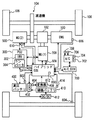
図1を参照して、本発明の第1の実施の形態に係る冷却ファンの制御装置を搭載した車両について説明する。この車両は、エンジン100と、MG(Motor Generator)(1)200と、PCU(Power Control Unit)300と、高圧バッテリ400と、冷却ファン402と、補機バッテリ410と、DC/DCコンバータ412と、MG(2)500と、ハイブリッドECU(Electronic Control Unit)600と、A/C(Air Conditioner)_ECU700と、A/Cユニット702とを含む。本本発明の実施の形態に係る冷却ファンの制御装置は、たとえばハイブリッドECU600が実行するプログラムにより実現される。
<First Embodiment>
A vehicle equipped with a cooling fan control device according to a first embodiment of the present invention will be described with reference to FIG. This vehicle includes an
なお、本実施の形態において、車両は、エンジン100を搭載したハイブリッド車両を用いて説明するが、ハイブリッド車両の代わりに、燃料電池を搭載した燃料電池車や、電気自動車などを用いてもよい。
In the present embodiment, the vehicle will be described using a hybrid vehicle equipped with
エンジン100は、燃料と空気との混合気を燃焼させてクランクシャフト(図示せず)を回転させ、駆動力を発生する。エンジン100が発生した駆動力は、動力分割機構102により、2経路に分割される。一方は減速機104を介して車輪106を駆動する経路である。もう一方は、MG(1)200を駆動させて発電する経路である。
MG(1)200は、動力分割機構102により分割されたエンジン100の駆動力により駆動させられ、発電する。MG(1)200により発電された電力は、車両の運転状態や、高圧バッテリ400のSOC(State Of Charge)の状態に応じて使い分けられる。たとえば、通常走行時や急加速時では、MG(1)200により発電された電力は、PCU300を介してMG(2)500に供給される。
MG (1) 200 is driven by the driving force of
一方、高圧バッテリ400のSOCが予め定められた値よりも低い場合、MG(1)200により発電された電力は、PCU300のインバータ302により交流電力から直流電力に変換され、コンバータ304により電圧が調整された後、高圧バッテリ400に蓄えられる。
On the other hand, when the SOC of
高圧バッテリ400のSOCは、電流センサ420により検知された入力電流および出力電流に基づいて、ハイブリッドECU600により推定される。なお、SOCを推定する方法は、公知の一般的な技術を利用すればよいため、ここではその詳細な説明は繰返さない。
The SOC of high-
高圧バッテリ400は、複数のバッテリセルを一体化したバッテリモジュールを、さらに複数直列に接続して構成された組電池である。なお、高圧バッテリ400の代わりに、キャパシタ(コンデンサ)を用いてもよい。高圧バッテリ400は、冷却ファン402により供給された冷却空気との間で熱交換が行なわれ、冷却される。冷却ファン402は、車室内の空気を高圧バッテリ400に対して供給する。
The high-
冷却ファン402には、高圧バッテリ400よりも定格電圧が低い補機バッテリ410から電力が供給される。なお、高圧バッテリ400の定格電圧は、たとえば300V程度であって、補機バッテリ410の定格電圧(出力時の定格電圧)は、たとえば14V程度である。冷却ファン402は、ハイブリッドECU600によりデューティ制御される。すなわち、冷却ファン402は、ハイブリッドECU600から冷却ファン402へ送信されるデューティ指令値(冷却ファン402に対するデューティ比の指令値)により制御される。
The cooling
ここで、デューティ制御とは、補機バッテリ410と冷却ファン402との間に設けられたスイッチング素子がオンになる比率(デューティ比)を制御することにより、冷却ファン402の作動電圧を制御することをいう。したがって、冷却ファン402の作動電圧は、デューティ指令値に対応した電圧になる。
Here, the duty control is to control the operating voltage of the cooling
補機バッテリ410には、DC/DCコンバータ412を介して高圧バッテリ400から電力が供給される。すなわち、高圧バッテリ400の出力電圧を、DC/DCコンバータ412により降圧することにより、補機バッテリ410が充電される。補機バッテリ410の電圧は、電圧センサ414により検知され、検知結果を表す信号がハイブリッドECU600に送信される。
The
なお、補機バッテリ410には、たとえば鉛蓄電池が用いられるが、その他、ニッケル水素電池やリチウム電池等であってもよく、キャパシタ(コンデンサ)等であってもよい。
In addition, although lead acid battery is used for the
MG(2)500は、三相交流回転電機である。MG(2)500は、高圧バッテリ400に蓄えられた電力およびMG(1)200により発電された電力の少なくともいずれか一方の電力により駆動する。MG(2)500の駆動力は、減速機104を介して車輪106に伝えられる。これにより、MG(2)500は、エンジン100をアシストして車両を走行させたり、MG(2)500からの駆動力のみにより車両を走行させたりする。
MG (2) 500 is a three-phase AC rotating electric machine. MG (2) 500 is driven by at least one of the electric power stored in
車両の回生制動時には、減速機104を介して車輪106によりMG(2)500が駆動させられ、MG(2)500が発電機として作動させられる。これによりMG(2)500は、制動エネルギを電力に変換する回生ブレーキとして作動する。MG(2)500により発電された電力は、インバータ302およびコンバータ304を介して高圧バッテリ400に蓄えられる。
During regenerative braking of the vehicle, the MG (2) 500 is driven by the
ハイブリッドECU600には、バッテリ温度センサ602、車速センサ604、クランクポジションセンサ606、回転数センサ(1)608および回転数センサ(2)610が接続されている。
The
バッテリ温度センサ602は、高圧バッテリ400の温度TBを検出する。車速センサ604は、車輪の回転数を検出する。クランクポジションセンサ606は、クランクシャフトに設けられたタイミングロータに対向して設けられており、クランクシャフトの回転数を検出する。回転数センサ(1)608は、MG(1)200の回転数を検出する。回転数センサ(2)610は、MG(2)500の回転数を検出する。
The battery temperature sensor 602 detects the temperature TB of the
バッテリ温度センサ602、車速センサ604、クランクポジションセンサ606、回転数センサ(1)608および回転数センサ(2)610の検出結果を表す信号は、ハイブリッドECU600に送信される。
Signals representing detection results of the battery temperature sensor 602, the
ハイブリッドECU600は、各センサから送信された信号、車両の運転状態、アクセル開度、アクセル開度の変化率、シフトポジション、高圧バッテリ400のSOCおよび温度、メモリ612に記憶されたマップおよびプログラムなどに基づいて演算処理を行なう。これにより、ハイブリッドECU600は、車両が所望の運転状態となるように車両に搭載された機器類を制御する。
The
A/C_ECU700には、A/Cユニット702が接続されている。A/C_ECU700は、車室内温度センサ706により検出された車室内温度および乗員により操作されるスイッチ708の操作状態に応じて、A/Cユニット702を制御する。A/Cユニット702からは、A/C_ECU700により設定された吹出し温度の空気が吹出される。
An A /
A/C_ECU700は、車室内温度に基づいて、A/Cファン704を駆動させる電圧を段階的に決定する。A/Cファン704を駆動させる電圧は、A/Cファン駆動段数を決定することにより決定される。決定されたA/Cファン駆動段数は、ハイブリッドECU600に送信される。
The A /
車速センサ604、クランクポジションセンサ606、回転数センサ(1)608および回転数センサ(2)610から送信された信号、A/Cファン駆動段数、補機類の作動音およびオーディオ(図示せず)の音量などに基づいて、ハイブリッドECU600により車室内における冷却ファン402の駆動音以外の騒音(暗騒音)が検出される。暗騒音は、たとえば予め実験などにより定められたマップにより検出すればよい。
ハイブリッドECU600は、高圧バッテリ400の温度TB、SOC、入出力電流、車室内の温度および暗騒音に基づいて、冷却ファン402の風量を示す冷却ファン402のファン駆動段数Fを設定する。
The
ファン駆動段数Fは、高圧バッテリ400の温度TBが高いほど、より高い段数に設定される。また、暗騒音が大きいほど、より高い段数に設定される。さらに、高圧バッテリ400のSOCや高圧バッテリ400からの入出力電流が高いほど、より高い段数に設定される。さらに、車室内の温度(冷却ファン402により送風される冷却空気(冷却風)の温度)と高圧バッテリ400の温度との差が小さいほど、より高い段数に設定される。ファン駆動段数Fが大きいほど、より高いデューティ指令値が設定される。
The fan drive stage number F is set to a higher stage number as the temperature TB of the high-
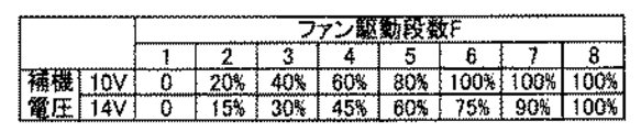
図2に示すように、ファン駆動段数Fに対応して、冷却ファン402へのデューティ指令値が補機バッテリ410の電圧毎に定められている。冷却ファン402を作動させる電圧は、各デューティ指令値に対応した電圧になる。したがって、冷却ファン402の作動電圧を制御することにより、冷却ファン402の風量(回転数)が制御される。なお、冷却ファン402の作動電圧(デューティ指令値)が高いほど、冷却ファン402の回転数が高くなる(風量が多くなる)。なお、図2に示すファン駆動段数Fおよび補機バッテリ410は一例であって、これらに限らない。
As shown in FIG. 2, a duty command value to cooling
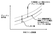
図3に示すように、同じファン駆動段数Fで比べた場合、補機バッテリ410の電圧が低いほど、デューティ指令値が高くされる。さらに、図3に示すように、ファン駆動段数Fが大きいほど、補機バッテリ410の電圧間におけるデューティ指令値の差が大きくなる。
As shown in FIG. 3, when compared at the same fan drive stage number F, the duty command value is increased as the voltage of the
冷却ファン402は、その回転数から変換される電圧を用いて、フィードバック制御される。すなわち、冷却ファン402の回転数センサ404により検知された回転数が、変換器406により電圧に変換される。変換器406により変換された電圧を表す信号がハイブリッドECU600に送信され、ハイブリッドECU600は、図2に示したマップにおけるデューティ指令値に対応した電圧(冷却ファン402の目標電圧)と、変換器406から送信された電圧とが一致するように、デューティ指令値を補正する。
The cooling
目標電圧よりも、変換器406から送信された電圧が高い場合、デューティ指令値が小さくなるように補正される。目標電圧よりも、変換器406から送信された電圧が低い場合、デューティ指令値が大きくなるように補正される。 When the voltage transmitted from the converter 406 is higher than the target voltage, the duty command value is corrected to be small. When the voltage transmitted from the converter 406 is lower than the target voltage, the duty command value is corrected so as to increase.
図4を参照して、本実施の形態に係る車両の制御装置においてハイブリッドECU600が実行するプログラムの制御構造について説明する。なお、以下に説明するプログラムは、予め定められた周期毎に繰り返し実行される。
Referring to FIG. 4, a control structure of a program executed by
ステップ(以下、ステップをSと略す)100にて、ハイブリッドECU600は、高圧バッテリ400の温度TB、SOC、入出力電流、車室内の温度および暗騒音に基づいて、冷却ファン402のファン駆動段数Fを設定する。
In step (hereinafter, step is abbreviated as S) 100,
S102にて、ハイブリッドECU600は、電圧センサ414から送信された信号に基づいて、補機バッテリ410の電圧を検知する。
In S102,
S104にて、ハイブリッドECU600は、ファン駆動段数Fおよび補機バッテリ410の電圧から、図2に示したマップに基づいて、冷却ファン402へのデューティ指令値を設定する。
In S104,
S106にて、ハイブリッドECU600は、設定されたデューティ指令値を冷却ファン402に送信する。すなわち、設定されたデューティ指定値で冷却ファン402を作動する。なお、このデューティ指令値は、フィードバック制御により補正される場合もある。
In S106,
以上のような構造およびフローチャートに基づく、本実施の形態に係る制御装置であるハイブリッドECU600の動作について説明する。
An operation of
車両の走行中において、高圧バッテリ400を冷却するために、高圧バッテリ400の温度TB、SOC、入出力電流、車室内の温度および暗騒音に基づいて、冷却ファン402のファン駆動段数Fが設定される(S100)。
In order to cool the high-
ところで、同じデューティ指令値で冷却ファン402を作動した場合であっても、冷却ファン402の電源である補機バッテリ410の電圧が異なれば、冷却ファン402に供給される電力に差が生じるため、冷却ファン402の回転数が異なり得る。すなわち、同じデューティ指令値(デューティ比)で冷却ファン402を制御した場合であっても、補機バッテリ410の電圧が高い場合は、低い場合に比べて、冷却ファン402の回転数が高くなり、風量が多くなり得る。この場合、冷却ファン402の作動音に対して乗員が不快感を感じる場合もある。
By the way, even if the cooling
そこで、本実施の形態においては、補機バッテリ410の電圧に応じてデューティ指令値を補正するために、電圧センサ414から送信された信号に基づいて、補機バッテリ410の電圧(出力電圧)が検知される(S102)。
Therefore, in the present embodiment, in order to correct the duty command value in accordance with the voltage of
この電圧(補機バッテリ410の電圧)と、設定されたファン駆動段数Fから、図2に示したマップに基づいて、冷却ファン402へのデューティ指令値が設定され(S104)、設定されたデューティ指定値で冷却ファン402が作動される(S106)。
From this voltage (the voltage of the auxiliary battery 410) and the set fan drive stage number F, the duty command value to the cooling
これにより、補機バッテリ410の電圧の変化に伴う冷却ファン402の回転数の変化を抑制することができる。
Thereby, the change of the rotation speed of the cooling
以上のように、本実施の形態に係る制御装置であるハイブリッドECUによれば、冷却ファンの電源である補機バッテリの電圧に応じたデューティ指令値が設定される。これにより、補機バッテリの電圧の変化に伴う冷却ファンの回転数の変化を抑制することができる。そのため、冷却ファンの回転数を精度よく制御することができる。 As described above, according to the hybrid ECU that is the control device according to the present embodiment, the duty command value according to the voltage of the auxiliary battery that is the power supply of the cooling fan is set. Thereby, the change of the rotation speed of the cooling fan accompanying the change of the voltage of an auxiliary battery can be suppressed. Therefore, the rotation speed of the cooling fan can be accurately controlled.
<第2の実施の形態>
以下、本発明の第2の実施の形態について説明する。本実施の形態は、デューティ指令値の下限値が補機バッテリの電圧に応じて設定される点で、前述の第1の実施の形態と相違する。その他の構造については、前述の第1の実施の形態と同じである。それらについての機能も同じである。したがって、それらについての詳細な説明はここでは繰返さない。
<Second Embodiment>
Hereinafter, a second embodiment of the present invention will be described. This embodiment is different from the first embodiment described above in that the lower limit value of the duty command value is set according to the voltage of the auxiliary battery. Other structures are the same as those in the first embodiment. The function about them is the same. Therefore, detailed description thereof will not be repeated here.
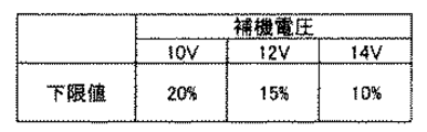
図5に示すように、ハイブリッドECU600は、補機バッテリ410の電圧をパラメータとしたマップを用いて、デューティ指令値の下限値を設定する。このマップによれば、補機バッテリ410の電圧が高いほど、デューティ指令値の下限値がより低く設定される。
As shown in FIG. 5,
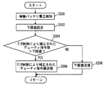
図6を参照して、本実施の形態に係る制御装置であるハイブリッドECU600が実行するプログラムの制御構造について説明する。なお、以下に説明するプログラムは、前述の第1の実施の形態におけるプログラムに加えて実行される。
With reference to FIG. 6, a control structure of a program executed by
S200にて、ハイブリッドECU600は、電圧センサ414から送信された信号に基づいて、補機バッテリ410の電圧を検知する。
In S200,
S202にて、ハイブリッドECU600は、図5に示したマップを用いて、デューティ指令値の下限値を設定する。
In S202,
S204にて、ハイブリッドECU600は、冷却ファン402の回転数に基づいたフィードバック制御により補正されたデューティ指令値が下限値よりも大きいか否かを判別する。フィードバック制御により補正されたデューティ指令値が下限値よりも大きいと(S204にてYES)、処理はS206に移される。もしそうでないと(S204にてNO)、処理はS208に移される。
In S204,
S206にて、ハイブリッドECU600は、フィードバック制御により補正されたデューティ指令値を冷却ファン402に送信する。すなわち、フィードバック制御により補正されたデューティ指定値で冷却ファン402を作動する。
In S206,
S208にて、ハイブリッドECU600は、デューティ指令値の下限値を冷却ファン402に送信する。すなわち、デューティ指令値の下限値で冷却ファン402を作動する。
In S208,
以上のような構造およびフローチャートに基づく、本実施の形態に係る制御装置であるハイブリッドECUの動作について説明する。 The operation of the hybrid ECU, which is the control device according to the present embodiment, based on the above-described structure and flowchart will be described.
図7の時間T(1)に示すように、冷却ファン402の実際の回転数が、前述した図2のマップを用いて設定されたデューティ指令値において期待される回転数(目標回転数)よりも大きい場合、冷却ファン402の作動電圧が高い状態であるため、フィードバック制御によりデューティ指令値が低くなるように補正される。
As shown at time T (1) in FIG. 7, the actual rotational speed of the cooling
このとき、図7に示すように、デューティ指令値が大きく低下されると、冷却ファン402の回転数が急低下し得る。冷却ファン402が大きく低下すると、フィードバック制御によりデューティ指令値が大きくなるよう補正され、冷却ファン402の回転数がハンチングし得る。冷却ファン402の回転数がハンチングすると、冷却ファン402の作動音が増減を繰り返し、乗員に違和感を与え得る。
At this time, as shown in FIG. 7, when the duty command value is greatly reduced, the rotational speed of the cooling
そこで、本実施の形態においては、補機バッテリ410の電圧に基づいて、デューティ指令値の下限値が設定される(S202)。フィードバック制御により補正されたデューティ指令値が下限値よりも大きいと(S204にてYES)、このデューティ指令値(フィードバック制御により補正されたデューティ指令値)で冷却ファン402が作動される(S206)。
Therefore, in the present embodiment, a lower limit value of the duty command value is set based on the voltage of auxiliary battery 410 (S202). If the duty command value corrected by feedback control is larger than the lower limit value (YES in S204), cooling
一方、フィードバック制御により補正されたデューティ指令値が下限値以下であると(S204にてNO)、デューティ指令値の下限値で冷却ファン402が作動される(S208)。これにより、図8に示すように、冷却ファン402の回転数が必要以上に低下することを抑制することができる。そのため、冷却ファン402の回転数がハンチングすることを抑制することができる。
On the other hand, when the duty command value corrected by the feedback control is equal to or lower than the lower limit value (NO in S204), cooling
以上のように、本実施の形態に係る制御装置であるハイブリッドECUによれば、補機バッテリの電圧に基づいて、デューティ指令値の下限値が設定される。これにより、冷却ファンの回転数が必要以上に低下することを抑制することができる。そのため、冷却ファンの回転数に基づいたフィードバック制御により、冷却ファンの回転数がハンチングすることを抑制することができる。 As described above, according to the hybrid ECU that is the control device according to the present embodiment, the lower limit value of the duty command value is set based on the voltage of the auxiliary battery. Thereby, it can suppress that the rotation speed of a cooling fan falls more than needed. Therefore, it is possible to suppress the hunting of the rotation speed of the cooling fan by feedback control based on the rotation speed of the cooling fan.
なお、デューティ指令値の下限値の代わりにもしくは加えて、上限値を設定するようにしてもよい。 An upper limit value may be set instead of or in addition to the lower limit value of the duty command value.
<第3の実施の形態>
以下、本発明の第3の実施の形態について説明する。本実施の形態は、冷却ファン402の回転数に基づいたフィードバック制御により補正されたデューティ指令値に基づいて、冷却ファン402が異常であるか否かを判定する点で、前述の第1の実施の形態および第2の実施の形態と相違する。その他の構造については、前述の第1の実施の形態および第2の実施の形態と同じである。それらについての機能も同じである。したがって、それらについての詳細な説明はここでは繰返さない。
<Third Embodiment>
Hereinafter, a third embodiment of the present invention will be described. The present embodiment is the first implementation described above in that it is determined whether or not the cooling
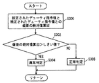
図9を参照して、本実施の形態に係る制御装置であるハイブリッドECU600が実行するプログラムの制御構造について説明する。なお、以下に説明するプログラムは、前述の第1の実施の形態および第2の実施の形態におけるプログラムに加えて実行される。
With reference to FIG. 9, a control structure of a program executed by
S300にて、ハイブリッドECU600は、前述した図2に示したマップを用いてファン駆動段数Fおよび補機バッテリ410の電圧から設定されたデューティ指令値と、フィードバック制御により補正されたデューティ指令値との偏差の絶対値を算出する。
In S300,
S302にて、ハイブリッドECU600は、偏差の絶対値がしきい値よりも大きいか否かを判別する。偏差の絶対値がしきい値よりも大きいと(S302にてYES)、処理はS304に移される。もしそうでないと(S302にてNO)、処理はS306に移される。
In S302,
S304にて、ハイブリッドECU600は、冷却ファン402が異常であると判定する。S306にて、ハイブリッドECU600は、冷却ファン402が正常であると判定する。
In S304,
以上のような構造およびフローチャートに基づく、本実施の形態に係る制御装置であるハイブリッドECU600の動作について説明する。
An operation of
冷却ファン402の作動中において、ファン駆動段数Fおよび補機バッテリ410の電圧から設定されたデューティ指令値と、フィードバック制御により補正されたデューティ指令値との偏差の絶対値が算出される(S300)。
During the operation of the cooling
図10に示すように、偏差の絶対値がしきい値よりも大きいと(S302にてYES)、ファン駆動段数Fおよび補機バッテリ410の電圧から設定されたデューティ指令値に応じた回転数で冷却ファン402が作動していない状態であるといえる。すなわち、冷却ファン402は、制御通りに作動していない状態であるといえる。
As shown in FIG. 10, when the absolute value of the deviation is larger than the threshold value (YES in S302), the rotational speed according to the duty command value set from the fan drive stage number F and the voltage of
この場合、冷却ファン402が異常であると判定される(S306)。一方、偏差の絶対値がしきい値以下であると(S304にてNO)、冷却ファン402が正常であると判定される(S306)。
In this case, it is determined that the cooling
このとき、補機バッテリ410の電圧に基づいて設定されるデューティ指令値を基準として、冷却ファン402の以上の有無が判定される。そのため、補機バッテリ410の電圧による冷却ファン402の回転数差を考慮して異常の有無を判定することができる。そのため、冷却ファン402の異常の有無を精度よく判定することができる。
At this time, the presence or absence of the cooling
以上のように、本実施の形態に係る制御装置であるハイブリッドECUによれば、補機バッテリの電圧に基づいて設定されるデューティ指令値とフィードバック制御により補正されたデューティ指令値との偏差の絶対値に基づいて、冷却ファンの異常の有無が判定される。これにより、冷却ファンの電源である補機バッテリの電圧による冷却ファンの回転数差を考慮して異常の有無を判定することができる。そのため、冷却ファンの異常の有無を精度よく判定することができる。 As described above, according to the hybrid ECU that is the control device according to the present embodiment, the absolute deviation between the duty command value that is set based on the voltage of the auxiliary battery and the duty command value that is corrected by feedback control. Based on the value, it is determined whether there is an abnormality in the cooling fan. Thereby, the presence or absence of abnormality can be determined in consideration of the difference in the number of rotations of the cooling fan due to the voltage of the auxiliary battery that is the power source of the cooling fan. Therefore, it is possible to accurately determine whether the cooling fan is abnormal.
<第4の実施の形態>
以下、本発明の第4の実施の形態について説明する。本実施の形態は、(システムの電源がオンにされた後であって、)補機バッテリ410への充電が開始される前において、デューティ指令値が低く設定されるとともに、フィードバック制御によるデューティ指令値の補正が禁止される点で、前述の第1〜第3の実施の形態と相違する。その他の構造については、前述の第1〜第3の実施の形態と同じである。それらについての機能も同じである。したがって、それらについての詳細な説明はここでは繰返さない。
<Fourth embodiment>
Hereinafter, a fourth embodiment of the present invention will be described. In the present embodiment, the duty command value is set to a low value (after the system power is turned on and before charging of the
図11を参照して、本実施の形態に係る制御装置であるハイブリッドECU600が実行するプログラムについて説明する。なお、以下に説明するプログラムは、前述の第1の実施の形態におけるプログラムの代わりに実行される。前述の第1の形態におけるプログラムと同じ処理については、同じステップ番号を付してある、それらについての機能についても同じである。したがって、ここではその詳細な説明は繰返さない。
Referring to FIG. 11, a program executed by
S400にて、ハイブリッドECU600は、補機バッテリ410への充電が開始される前(充電停止中)であるか否かを判別する。補機バッテリ410への充電が開始される前であると(S400にてYES)、処理はS402に移される。もしそうでないと(S400にてNO)、処理はS404に移される。
In S400,
S402にて、ハイブリッドECU600は、前述した図2に示したマップを用いてファン駆動段数Fおよび補機バッテリ410の電圧から設定されたデューティ指令値よりも予め定められた値だけ低いデューティ指令値を冷却ファン402に送信するとともに、フィードバック制御によるデューティ指令値を禁止する。このとき、充電が開始された後における補機バッテリ410の電圧に応じたデューティ指令値が冷却ファン402に送信される。
In S402,
S404にて、ハイブリッドECU600は、ファン駆動段数Fおよび補機バッテリ410の電圧から設定されたデューティ指令値を冷却ファン402に送信するとともに、フィードバック制御によるデューティ指令値を許可する。
In S404,
以上のような構造およびフローチャートに基づく、本実施の形態に係る制御装置であるハイブリッドECU600の動作について説明する。
An operation of
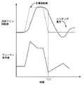
図12の時間T(2)に示すように、補機バッテリ410の充電開始時には、補機バッテリ410の電圧が急上昇する。このとき、冷却ファン402の回転数が急上昇し得る。冷却ファン402の回転数が急上昇すると、フィードバック制御によりデューティ指令値が低下され、冷却ファン402が急低下せしめられる。このような回転数の急変化が繰返されると、冷却ファン402の作動音が急変し、乗員に違和感を与え得る。
As shown at time T (2) in FIG. 12, at the start of charging of
そこで、本実施の形態においては、補機バッテリ410への充電が開始される前(充電停止中)であると(S400にてYES)、ファン駆動段数Fおよび補機バッテリ410の電圧から設定されたデューティ指令値よりも予め定められた値だけ低いデューティ指令値が冷却ファン402に送信される(S402)。また、このデューティ指令値(低く設定されたデューティ指令値)を維持するために、フィードバック制御によるデューティ指令値が禁止される(S402)。
Therefore, in the present embodiment, when charging to
これにより、補機バッテリ410への充電開始時において電圧が急上昇する前に、予めデューティ指令値を低くすることができる。そのため、図13に示すように、補機バッテリ410への充電開始時において電圧が急上昇した場合において、冷却ファン402の回転数が急上昇することを抑制することができる。
Thereby, the duty command value can be lowered in advance before the voltage suddenly rises at the start of charging of
補機バッテリ410への充電が開始されると(S400にてNO)、ファン駆動段数Fおよび補機バッテリ410の電圧から設定されたデューティ指令値が冷却ファン402に送信されるとともに、フィードバック制御によるデューティ指令値が許可される(S404)。
When charging of
以上のように、本実施の形態に係る制御装置に係る制御装置であるハイブリッドECUによれば、補機バッテリへの充電開始前において、補機バッテリの電圧に基づいて設定されたデューティ指令値よりも低いデューティ指令値で冷却ファンが作動されるとともに、フィードバック制御によるデューティ指令値の補正が禁止される。これにより、補機バッテリへの充電開始時において電圧が急上昇する前に、予めデューティ指令値を低くすることができる。そのため、補機バッテリへの充電開始時において電圧が急上昇した場合において、冷却ファンの回転数が急上昇すること(あるいは急上昇後の回転数)を抑制することができる。 As described above, according to the hybrid ECU that is the control device according to the control device according to the present embodiment, before starting charging of the auxiliary battery, from the duty command value set based on the voltage of the auxiliary battery. The cooling fan is operated with a lower duty command value, and correction of the duty command value by feedback control is prohibited. As a result, the duty command value can be lowered in advance before the voltage suddenly rises at the start of charging of the auxiliary battery. Therefore, when the voltage suddenly increases at the start of charging of the auxiliary battery, it is possible to suppress the rapid increase in the number of rotations of the cooling fan (or the number of rotations after the rapid increase).
なお、本実施の形態においては、補機バッテリ410への充電が開始される前、すなわち補機バッテリ410の電圧が急上昇する前において、予めデューティ指令値を低く設定していたが、充電を行なうことができる状態(たとえば高圧バッテリ400と補機バッテリ410との間に設けられたリレーがオンになる前において、予めデューティ指令値を低く設定するようにしてもよい。
In this embodiment, the duty command value is set low before charging of
また、補機バッテリ410の電圧が急低下する前において、予めデューティ指令値を高く設定するようにしてもよい。
Further, the duty command value may be set to be high in advance before the voltage of
さらに、デューティ指令値(デューティ比)の代わりに、その他、補機バッテリ410と冷却ファン402との間における抵抗値等を変化させることにより、冷却ファン402の回転数を制御するようにしてもよい。
Furthermore, instead of the duty command value (duty ratio), the rotational speed of the cooling
さらに、前述の第1〜第4の本実施の形態では動力分割機構102によりエンジン100の動力を車軸とMG(1)200とに分割して伝達可能なシリーズ/パラレル型ハイブリッドシステムに適用した例を示した。しかし本発明は、発電機を駆動するためにのみエンジンを用い、発電機により発電された電力を使うモータでのみ車軸の駆動力を発生させるシリーズ型ハイブリッド自動車や、モータのみで走行する電気自動車にも適用できる。
Further, in the first to fourth embodiments described above, an example is applied to a series / parallel type hybrid system in which the
今回開示された実施の形態は、すべての点で例示であって制限的なものではないと考えられるべきである。本発明の範囲は上記した説明ではなくて特許請求の範囲によって示され、特許請求の範囲と均等の意味および範囲内でのすべての変更が含まれることが意図さ
れる。
The embodiment disclosed this time should be considered as illustrative in all points and not restrictive. The scope of the present invention is defined by the terms of the claims, rather than the description above, and is intended to include any modifications within the scope and meaning equivalent to the terms of the claims.
100 エンジン、102 動力分割機構、104 減速機、106 車輪、200 MG(1)、300 PCU、302 インバータ、304 コンバータ、400 高圧バッテリ、402 冷却ファン、404 回転数センサ、406 変換器、410 補機バッテリ、412 DC/DCコンバータ、414 電圧センサ、420 電流センサ、500 MG(1)、600 ハイブリッドECU、602 バッテリ温度センサ、604 車速センサ、606 クランクポジションセンサ、608 回転数センサ(1)、610 回転数センサ(2)、612 メモリ、700 A/C_ECU、702 A/Cユニット、704 A/Cファン、706 車室内温度センサ、708 スイッチ。 100 engine, 102 power split mechanism, 104 speed reducer, 106 wheels, 200 MG (1), 300 PCU, 302 inverter, 304 converter, 400 high voltage battery, 402 cooling fan, 404 speed sensor, 406 converter, 410 auxiliary machine Battery, 412 DC / DC converter, 414 Voltage sensor, 420 Current sensor, 500 MG (1), 600 Hybrid ECU, 602 Battery temperature sensor, 604 Vehicle speed sensor, 606 Crank position sensor, 608 Rotational speed sensor (1), 610 revolutions Number sensor (2), 612 memory, 700 A / C_ECU, 702 A / C unit, 704 A / C fan, 706 interior temperature sensor, 708 switch.
Claims (10)
前記冷却ファンの回転数を制御するための制御手段と、
前記第1の蓄電機構の電圧を検知するための検知手段と、
前記第1の蓄電機構の電圧に応じて、前記冷却ファンの回転数を変化させるための制御値を設定するための設定手段とを含む、冷却ファンの制御装置。 A control device for a cooling fan that generates cooling air that cools the second power storage mechanism by receiving power supplied from the first power storage mechanism and driving the power storage mechanism.
Control means for controlling the number of rotations of the cooling fan;
Detecting means for detecting a voltage of the first power storage mechanism;
A cooling fan control device comprising: setting means for setting a control value for changing the number of revolutions of the cooling fan according to the voltage of the first power storage mechanism.
前記冷却ファンが予め定められた運転状態になるように、前記冷却ファンの運転状態に基づいたフィードバック制御により、制御値を補正するための補正手段と、
前記補正手段により補正された制御値と前記設定手段により設定された制御値との差が予め定められた値より大きい場合、前記冷却ファンが異常であると判定するための判定手段とをさらに含む、請求項1〜6のいずれかに記載の冷却ファンの制御装置。 The controller is
Correction means for correcting the control value by feedback control based on the operation state of the cooling fan so that the cooling fan is in a predetermined operation state;
And a determination unit for determining that the cooling fan is abnormal when a difference between the control value corrected by the correction unit and the control value set by the setting unit is larger than a predetermined value. The cooling fan control device according to any one of claims 1 to 6.
前記冷却ファンが予め定められた運転状態になるように、前記冷却ファンの運転状態に基づいたフィードバック制御により、制御値を補正するための補正手段と、
前記第1の蓄電機構に関する予め定められた条件が満たされた場合は、前記フィードバック制御による制御値の補正を禁止するための手段と、
前記予め定められた条件が満たされた場合は、前記設定手段により設定される制御値とは異なる制御値を設定するための手段とをさらに含む、請求項1〜6のいずれかに記載の冷却ファンの制御装置。 The controller is
Correction means for correcting the control value by feedback control based on the operation state of the cooling fan so that the cooling fan is in a predetermined operation state;
Means for prohibiting correction of the control value by the feedback control when a predetermined condition regarding the first power storage mechanism is satisfied;
The cooling according to any one of claims 1 to 6, further comprising means for setting a control value different from the control value set by the setting means when the predetermined condition is satisfied. Fan control device.
Priority Applications (6)
| Application Number | Priority Date | Filing Date | Title |
|---|---|---|---|
| JP2006019630A JP4848780B2 (en) | 2006-01-27 | 2006-01-27 | Control device for cooling fan |
| KR1020087020832A KR101050487B1 (en) | 2006-01-27 | 2006-12-21 | Cooling fan control device and control method |
| US12/087,785 US8219248B2 (en) | 2006-01-27 | 2006-12-21 | Control device and control method for cooling fan |
| PCT/JP2006/326182 WO2007086231A1 (en) | 2006-01-27 | 2006-12-21 | Cooling fan control device and method |
| CN2006800517219A CN101366144B (en) | 2006-01-27 | 2006-12-21 | Control device and control method for cooling fan |
| EP06843560.1A EP1983603B1 (en) | 2006-01-27 | 2006-12-21 | Cooling fan control device and method |
Applications Claiming Priority (1)
| Application Number | Priority Date | Filing Date | Title |
|---|---|---|---|
| JP2006019630A JP4848780B2 (en) | 2006-01-27 | 2006-01-27 | Control device for cooling fan |
Publications (3)
| Publication Number | Publication Date |
|---|---|
| JP2007200780A true JP2007200780A (en) | 2007-08-09 |
| JP2007200780A5 JP2007200780A5 (en) | 2008-04-24 |
| JP4848780B2 JP4848780B2 (en) | 2011-12-28 |
Family
ID=38309032
Family Applications (1)
| Application Number | Title | Priority Date | Filing Date |
|---|---|---|---|
| JP2006019630A Active JP4848780B2 (en) | 2006-01-27 | 2006-01-27 | Control device for cooling fan |
Country Status (6)
| Country | Link |
|---|---|
| US (1) | US8219248B2 (en) |
| EP (1) | EP1983603B1 (en) |
| JP (1) | JP4848780B2 (en) |
| KR (1) | KR101050487B1 (en) |
| CN (1) | CN101366144B (en) |
| WO (1) | WO2007086231A1 (en) |
Cited By (11)
| Publication number | Priority date | Publication date | Assignee | Title |
|---|---|---|---|---|
| EP2109178A1 (en) * | 2008-04-10 | 2009-10-14 | Peugeot Citroën Automobiles S.A. | Method for controlling a device for thermal control of a battery supplying an electrically powered vehicle |
| JP2010146920A (en) * | 2008-12-19 | 2010-07-01 | Toyota Motor Corp | Cooling device, vehicle loading the same, and control method for cooling device |
| JP2011055644A (en) * | 2009-09-02 | 2011-03-17 | Toshiba Mitsubishi-Electric Industrial System Corp | Uninterruptible power supply unit |
| JP2011194020A (en) * | 2010-03-19 | 2011-10-06 | Panasonic Corp | Rice cooker |
| JP2015047027A (en) * | 2013-08-29 | 2015-03-12 | 三菱自動車工業株式会社 | Electric vehicle charging system |
| JP2015511372A (en) * | 2012-02-03 | 2015-04-16 | ローベルト ボッシュ ゲゼルシャフト ミット ベシュレンクテル ハフツング | Control device for closed-loop control of a cooling circuit that regulates the temperature of a battery system with more than one heating and / or cooling element |
| JP2016120780A (en) * | 2014-12-24 | 2016-07-07 | トヨタ自動車株式会社 | Control system of hybrid vehicle |
| JP2016199151A (en) * | 2015-04-10 | 2016-12-01 | トヨタ自動車株式会社 | Cooling system for on-vehicle secondary battery |
| JP2017103128A (en) * | 2015-12-03 | 2017-06-08 | オートモーティブエナジーサプライ株式会社 | Cooling fan controller of battery pack |
| JP2018019504A (en) * | 2016-07-27 | 2018-02-01 | トヨタ自動車株式会社 | Power supply system for electric vehicle |
| WO2021085866A1 (en) * | 2019-10-28 | 2021-05-06 | 주식회사 엘지화학 | System and method for cooling battery modules included in energy storage system (ess) |
Families Citing this family (36)
| Publication number | Priority date | Publication date | Assignee | Title |
|---|---|---|---|---|
| JP4466595B2 (en) * | 2006-03-28 | 2010-05-26 | トヨタ自動車株式会社 | COOLING SYSTEM, AUTOMOBILE MOUNTING THE SAME, AND COOLING SYSTEM CONTROL METHOD |
| JP4327823B2 (en) | 2006-06-15 | 2009-09-09 | トヨタ自動車株式会社 | COOLING SYSTEM, AUTOMOBILE MOUNTING THE SAME, AND COOLING SYSTEM CONTROL METHOD |
| US7793746B2 (en) | 2007-03-09 | 2010-09-14 | Gm Global Technology Operations, Inc. | Noise-comfort function for cooling systems with proportional variable speed fans |
| US8465350B2 (en) * | 2007-06-28 | 2013-06-18 | GM Global Technology Operations LLC | Control method for RESS fan operation in a vehicle |
| FR2935646B1 (en) * | 2008-09-11 | 2010-12-03 | Peugeot Citroen Automobiles Sa | METHOD FOR CONTROLLING A THERMOREGULATION DEVICE OF A POWER BATTERY OF A POWER-DRIVEN VEHICLE |
| DE102009031295A1 (en) * | 2009-06-30 | 2011-01-05 | Fev Motorentechnik Gmbh | Power storage device |
| US20110048825A1 (en) * | 2009-08-28 | 2011-03-03 | Gary Starr | Air conditioner for electric car |
| FR2963167B1 (en) * | 2010-07-20 | 2013-03-08 | Peugeot Citroen Automobiles Sa | DEVICE AND METHOD FOR COOLING A MEANS FOR STORING ELECTRIC ENERGY |
| WO2012033234A1 (en) * | 2010-09-06 | 2012-03-15 | 볼보 컨스트럭션 이큅먼트 에이비 | Energy repository discharge system for construction machinery |
| KR101297005B1 (en) * | 2010-12-16 | 2013-08-14 | 삼성에스디아이 주식회사 | Apparatus and method for Battery temperature control |
| US8651209B2 (en) * | 2010-12-20 | 2014-02-18 | Sony Corporation | Kinetic energy storage systems and methods of use |
| CN102544618B (en) * | 2010-12-30 | 2014-08-13 | 上海航天电源技术有限责任公司 | Liquid cooling temperature control and management method of power lithium ion battery |
| JP5812522B2 (en) * | 2011-11-21 | 2015-11-17 | トヨタ自動車株式会社 | Fuel cell system |
| KR101438901B1 (en) * | 2012-08-23 | 2014-09-16 | 현대자동차주식회사 | Blower control device and method for high voltage battery |
| DE102012016801B3 (en) * | 2012-08-23 | 2014-02-13 | Audi Ag | Motor vehicle with battery cooling |
| EP2899044B1 (en) * | 2012-09-19 | 2017-07-05 | Nissan Motor Company, Limited | Cooling and heating air conditioner |
| JP6113455B2 (en) * | 2012-10-12 | 2017-04-12 | 日野自動車株式会社 | On-vehicle power control device cooling system and abnormality diagnosis method thereof |
| CN104042122B (en) * | 2013-03-17 | 2016-02-17 | 李昆生 | The smoke-free electric barbecue grill in many barbecues chamber |
| JP6187309B2 (en) | 2014-02-21 | 2017-08-30 | トヨタ自動車株式会社 | Electric vehicle power supply device |
| JP6330219B2 (en) * | 2014-03-17 | 2018-05-30 | 株式会社デンソー | Motor control device |
| US10059222B2 (en) | 2014-04-15 | 2018-08-28 | Ford Global Technologies, Llc | Battery temperature estimation system |
| KR101575480B1 (en) * | 2014-05-28 | 2015-12-07 | 현대자동차주식회사 | Control method for cooling fan in a low temperature state |
| US9207732B1 (en) | 2015-02-25 | 2015-12-08 | Quanta Computer Inc. | Optimized fan duty control for computing device |
| JP6269559B2 (en) * | 2015-04-10 | 2018-01-31 | トヨタ自動車株式会社 | In-vehicle secondary battery cooling system |
| CN104863684B (en) * | 2015-06-09 | 2017-12-08 | 宝沃汽车(中国)有限公司 | The monitoring method and monitoring system of vehicle and its cooling fan motor |
| DE102016202807B4 (en) * | 2016-02-24 | 2022-12-22 | Audi Ag | Method for charging an accumulator of an electrically drivable motor vehicle |
| WO2018189872A1 (en) | 2017-04-13 | 2018-10-18 | 三菱電機株式会社 | Power conversion device, control system for power conversion device, electronic device, and control method for cooling fan |
| JP6787242B2 (en) * | 2017-04-28 | 2020-11-18 | トヨタ自動車株式会社 | Power system |
| JP6496790B2 (en) * | 2017-09-08 | 2019-04-03 | 株式会社Subaru | In-vehicle equipment cooling system |
| DE102018204992A1 (en) * | 2018-04-04 | 2019-10-10 | Bayerische Motoren Werke Aktiengesellschaft | Device and method for controlling a charging of an electrical energy storage of a motor vehicle and charging system for an electrical energy storage |
| GB201819022D0 (en) * | 2018-11-22 | 2019-01-09 | Jaguar Land Rover Ltd | Vehicle controller and control method |
| CN112803036B (en) * | 2019-11-14 | 2023-04-14 | 宇通客车股份有限公司 | Fuel cell thermal management system and control method thereof |
| KR102287330B1 (en) | 2019-11-15 | 2021-08-06 | 삼성에스디아이 주식회사 | Fan fault detection device |
| CN111987386B (en) * | 2020-08-31 | 2021-11-12 | 东方醒狮(福建)储能科技有限公司 | High-temperature fault cooling protection system for lithium power battery and control method thereof |
| CN112026508B (en) * | 2020-09-07 | 2021-07-02 | 东风小康汽车有限公司重庆分公司 | Control method for cooling fan of extended range electric vehicle |
| CN112228367A (en) * | 2020-09-27 | 2021-01-15 | 宝能(西安)汽车研究院有限公司 | Method for controlling cooling fan of vehicle battery system |
Citations (8)
| Publication number | Priority date | Publication date | Assignee | Title |
|---|---|---|---|---|
| JPH01135603A (en) * | 1987-11-20 | 1989-05-29 | Sanyo Electric Co Ltd | Cooling device of mold |
| JPH02168865A (en) * | 1988-12-22 | 1990-06-28 | Hitachi Ltd | Pulse modulator and capacitor charging device |
| JPH08148190A (en) * | 1994-11-25 | 1996-06-07 | Nissan Motor Co Ltd | Battery cooling device |
| JPH11238530A (en) * | 1998-02-23 | 1999-08-31 | Matsushita Electric Ind Co Ltd | Cooling method for modular battery and its manufacture |
| JP2002151166A (en) * | 2000-11-10 | 2002-05-24 | Japan Storage Battery Co Ltd | Method and device for temperature adjustment of secondary battery |
| JP2003111291A (en) * | 2001-10-03 | 2003-04-11 | Matsushita Electric Ind Co Ltd | Control method for charging secondary battery used in fuel battery power generating system |
| JP2003274572A (en) * | 2002-03-15 | 2003-09-26 | Nippon Telegr & Teleph Corp <Ntt> | Power unit |
| JP2004080914A (en) * | 2002-08-19 | 2004-03-11 | Sanyo Electric Co Ltd | Electric vehicle |
Family Cites Families (20)
| Publication number | Priority date | Publication date | Assignee | Title |
|---|---|---|---|---|
| JPS61147708A (en) * | 1984-12-19 | 1986-07-05 | Yamaha Motor Co Ltd | Drive controller of electric automobile |
| JPS6438521A (en) * | 1987-07-31 | 1989-02-08 | Noritz Corp | Safety device for combustor |
| JP3220494B2 (en) * | 1992-01-09 | 2001-10-22 | マツダ株式会社 | Ventilation control device for vehicles |
| JP2001210389A (en) | 2000-01-31 | 2001-08-03 | Sanyo Electric Co Ltd | Electric power supply equipped with battery |
| JP2002051479A (en) | 2000-07-31 | 2002-02-15 | Sanyo Electric Co Ltd | Method and apparatus for charging battery |
| JP2003061400A (en) * | 2001-08-20 | 2003-02-28 | Nissan Motor Co Ltd | Control equipment of generator for mobile |
| US20030107341A1 (en) * | 2001-12-11 | 2003-06-12 | Georgia-Pacific Corporation | Motor control usable with high ripple BEMF feedback signal to achieve precision burst mode motor operation |
| JP4053289B2 (en) * | 2001-12-12 | 2008-02-27 | 本田技研工業株式会社 | Storage battery temperature control device and vehicle device using the same |
| JP3843956B2 (en) * | 2002-05-14 | 2006-11-08 | トヨタ自動車株式会社 | In-vehicle battery fan control method and fan control device |
| TWI230493B (en) * | 2002-10-11 | 2005-04-01 | Hitachi Koki Kk | Charging apparatus |
| JP2005063689A (en) * | 2003-08-12 | 2005-03-10 | Nissan Motor Co Ltd | Battery cooling control device |
| JP2005184979A (en) | 2003-12-19 | 2005-07-07 | Sanyo Electric Co Ltd | Power unit for vehicle, and power unit for hybrid car |
| US7479753B1 (en) * | 2004-02-24 | 2009-01-20 | Nvidia Corporation | Fan speed controller |
| JP2005333738A (en) * | 2004-05-20 | 2005-12-02 | Toyota Motor Corp | Cooling device controller, cooling device fault detector, cooling device fault detecting method and computer readable recording medium recording program for performing fault detection of cooling device by computer |
| JP4792712B2 (en) * | 2004-06-02 | 2011-10-12 | トヨタ自動車株式会社 | Power supply cooling system |
| KR20060024917A (en) * | 2004-09-15 | 2006-03-20 | 현대모비스 주식회사 | Apparatus for correcting the power of a actuator in a vehicle and method therefor |
| US7441616B2 (en) * | 2004-12-27 | 2008-10-28 | Nissan Motor Co., Ltd. | Generated power control system |
| JP4791054B2 (en) * | 2005-03-02 | 2011-10-12 | プライムアースEvエナジー株式会社 | Temperature management device and power supply device |
| JP5091579B2 (en) * | 2007-07-26 | 2012-12-05 | 矢崎総業株式会社 | Load control device |
| JP4947045B2 (en) * | 2008-12-19 | 2012-06-06 | トヨタ自動車株式会社 | Cooling device and vehicle equipped with the same |
-
2006
- 2006-01-27 JP JP2006019630A patent/JP4848780B2/en active Active
- 2006-12-21 US US12/087,785 patent/US8219248B2/en active Active
- 2006-12-21 CN CN2006800517219A patent/CN101366144B/en not_active Expired - Fee Related
- 2006-12-21 EP EP06843560.1A patent/EP1983603B1/en not_active Expired - Fee Related
- 2006-12-21 KR KR1020087020832A patent/KR101050487B1/en active IP Right Grant
- 2006-12-21 WO PCT/JP2006/326182 patent/WO2007086231A1/en active Application Filing
Patent Citations (8)
| Publication number | Priority date | Publication date | Assignee | Title |
|---|---|---|---|---|
| JPH01135603A (en) * | 1987-11-20 | 1989-05-29 | Sanyo Electric Co Ltd | Cooling device of mold |
| JPH02168865A (en) * | 1988-12-22 | 1990-06-28 | Hitachi Ltd | Pulse modulator and capacitor charging device |
| JPH08148190A (en) * | 1994-11-25 | 1996-06-07 | Nissan Motor Co Ltd | Battery cooling device |
| JPH11238530A (en) * | 1998-02-23 | 1999-08-31 | Matsushita Electric Ind Co Ltd | Cooling method for modular battery and its manufacture |
| JP2002151166A (en) * | 2000-11-10 | 2002-05-24 | Japan Storage Battery Co Ltd | Method and device for temperature adjustment of secondary battery |
| JP2003111291A (en) * | 2001-10-03 | 2003-04-11 | Matsushita Electric Ind Co Ltd | Control method for charging secondary battery used in fuel battery power generating system |
| JP2003274572A (en) * | 2002-03-15 | 2003-09-26 | Nippon Telegr & Teleph Corp <Ntt> | Power unit |
| JP2004080914A (en) * | 2002-08-19 | 2004-03-11 | Sanyo Electric Co Ltd | Electric vehicle |
Cited By (14)
| Publication number | Priority date | Publication date | Assignee | Title |
|---|---|---|---|---|
| EP2109178A1 (en) * | 2008-04-10 | 2009-10-14 | Peugeot Citroën Automobiles S.A. | Method for controlling a device for thermal control of a battery supplying an electrically powered vehicle |
| JP2010146920A (en) * | 2008-12-19 | 2010-07-01 | Toyota Motor Corp | Cooling device, vehicle loading the same, and control method for cooling device |
| US8418789B2 (en) | 2008-12-19 | 2013-04-16 | Toyota Jidosha Kabushiki Kaisha | Cooling system, vehicle equipped with the cooling system, and method for controlling the cooling system |
| JP2011055644A (en) * | 2009-09-02 | 2011-03-17 | Toshiba Mitsubishi-Electric Industrial System Corp | Uninterruptible power supply unit |
| JP2011194020A (en) * | 2010-03-19 | 2011-10-06 | Panasonic Corp | Rice cooker |
| JP2015511372A (en) * | 2012-02-03 | 2015-04-16 | ローベルト ボッシュ ゲゼルシャフト ミット ベシュレンクテル ハフツング | Control device for closed-loop control of a cooling circuit that regulates the temperature of a battery system with more than one heating and / or cooling element |
| JP2015047027A (en) * | 2013-08-29 | 2015-03-12 | 三菱自動車工業株式会社 | Electric vehicle charging system |
| JP2016120780A (en) * | 2014-12-24 | 2016-07-07 | トヨタ自動車株式会社 | Control system of hybrid vehicle |
| US9758055B2 (en) | 2014-12-24 | 2017-09-12 | Toyota Jidosha Kabushiki Kaisha | Control system for hybrid vehicle |
| JP2016199151A (en) * | 2015-04-10 | 2016-12-01 | トヨタ自動車株式会社 | Cooling system for on-vehicle secondary battery |
| US10297883B2 (en) | 2015-04-10 | 2019-05-21 | Toyota Jidosha Kabushiki Kaisha | Cooling system for on-vehicle secondary battery |
| JP2017103128A (en) * | 2015-12-03 | 2017-06-08 | オートモーティブエナジーサプライ株式会社 | Cooling fan controller of battery pack |
| JP2018019504A (en) * | 2016-07-27 | 2018-02-01 | トヨタ自動車株式会社 | Power supply system for electric vehicle |
| WO2021085866A1 (en) * | 2019-10-28 | 2021-05-06 | 주식회사 엘지화학 | System and method for cooling battery modules included in energy storage system (ess) |
Also Published As
| Publication number | Publication date |
|---|---|
| EP1983603B1 (en) | 2014-03-12 |
| EP1983603A1 (en) | 2008-10-22 |
| JP4848780B2 (en) | 2011-12-28 |
| CN101366144A (en) | 2009-02-11 |
| US20090024252A1 (en) | 2009-01-22 |
| KR101050487B1 (en) | 2011-07-20 |
| WO2007086231A1 (en) | 2007-08-02 |
| EP1983603A4 (en) | 2012-09-12 |
| US8219248B2 (en) | 2012-07-10 |
| CN101366144B (en) | 2012-07-25 |
| KR20080091495A (en) | 2008-10-13 |
Similar Documents
| Publication | Publication Date | Title |
|---|---|---|
| JP4848780B2 (en) | Control device for cooling fan | |
| US10381695B2 (en) | Cooling system for secondary battery | |
| JP6222159B2 (en) | In-vehicle secondary battery cooling system | |
| JP3638263B2 (en) | Vehicle drive device | |
| JP4947045B2 (en) | Cooling device and vehicle equipped with the same | |
| JP2009107619A (en) | Method and system for alerting driver that motive power system is about to be activated | |
| JP6683949B2 (en) | Vehicle drive device | |
| KR101807364B1 (en) | Vehicle driven by electric motor and control method for vehicle | |
| JP3918663B2 (en) | Vehicle control device, control method, program for realizing the method, and recording medium recording the program | |
| US20120049806A1 (en) | Generation control device | |
| JP2010161904A (en) | Drive controller of cooling fan | |
| JP2010273492A (en) | Battery device | |
| JP6287938B2 (en) | In-vehicle secondary battery cooling system | |
| JP2011083076A (en) | Vehicle and control method therefor | |
| JP2007282315A (en) | Fan control device of fuel battery vehicle | |
| US20210291661A1 (en) | Electric vehicle | |
| JP2008001301A (en) | Controller of hybrid vehicle | |
| JP2005204481A (en) | Device for controlling cooling fan of electricity-accumulating mechanism | |
| JP2010154654A (en) | Vehicle battery cooling control unit | |
| JP4096885B2 (en) | Cooling device for power conversion mechanism mounted on vehicle | |
| JP2007295785A (en) | Control unit for converter | |
| JP4285638B2 (en) | Vehicle charging control device | |
| JP2006121786A (en) | Drive system for vehicle | |
| JP2005306197A (en) | Controller of vehicle | |
| JP2004112997A (en) | Controller for hybrid vehicle |
Legal Events
| Date | Code | Title | Description |
|---|---|---|---|
| A521 | Written amendment |
Free format text: JAPANESE INTERMEDIATE CODE: A523 Effective date: 20080312 |
|
| A621 | Written request for application examination |
Free format text: JAPANESE INTERMEDIATE CODE: A621 Effective date: 20080312 |
|
| A131 | Notification of reasons for refusal |
Free format text: JAPANESE INTERMEDIATE CODE: A131 Effective date: 20110823 |
|
| A521 | Written amendment |
Free format text: JAPANESE INTERMEDIATE CODE: A523 Effective date: 20110901 |
|
| TRDD | Decision of grant or rejection written | ||
| A01 | Written decision to grant a patent or to grant a registration (utility model) |
Free format text: JAPANESE INTERMEDIATE CODE: A01 Effective date: 20110920 |
|
| A01 | Written decision to grant a patent or to grant a registration (utility model) |
Free format text: JAPANESE INTERMEDIATE CODE: A01 |
|
| A61 | First payment of annual fees (during grant procedure) |
Free format text: JAPANESE INTERMEDIATE CODE: A61 Effective date: 20111003 |
|
| R151 | Written notification of patent or utility model registration |
Ref document number: 4848780 Country of ref document: JP Free format text: JAPANESE INTERMEDIATE CODE: R151 |
|
| FPAY | Renewal fee payment (event date is renewal date of database) |
Free format text: PAYMENT UNTIL: 20141028 Year of fee payment: 3 |