JP2006504209A - A customizable and robust computer processing system - Google Patents
A customizable and robust computer processing system Download PDFInfo
- Publication number
- JP2006504209A JP2006504209A JP2005501660A JP2005501660A JP2006504209A JP 2006504209 A JP2006504209 A JP 2006504209A JP 2005501660 A JP2005501660 A JP 2005501660A JP 2005501660 A JP2005501660 A JP 2005501660A JP 2006504209 A JP2006504209 A JP 2006504209A
- Authority
- JP
- Japan
- Prior art keywords
- control unit
- external object
- processing control
- customizable
- storage module
- Prior art date
- Legal status (The legal status is an assumption and is not a legal conclusion. Google has not performed a legal analysis and makes no representation as to the accuracy of the status listed.)
- Pending
Links
Images


Classifications
-
- H—ELECTRICITY
- H05—ELECTRIC TECHNIQUES NOT OTHERWISE PROVIDED FOR
- H05K—PRINTED CIRCUITS; CASINGS OR CONSTRUCTIONAL DETAILS OF ELECTRIC APPARATUS; MANUFACTURE OF ASSEMBLAGES OF ELECTRICAL COMPONENTS
- H05K5/00—Casings, cabinets or drawers for electric apparatus
- H05K5/04—Metal casings
-
- G—PHYSICS
- G06—COMPUTING; CALCULATING OR COUNTING
- G06F—ELECTRIC DIGITAL DATA PROCESSING
- G06F1/00—Details not covered by groups G06F3/00 - G06F13/00 and G06F21/00
- G06F1/16—Constructional details or arrangements
- G06F1/1601—Constructional details related to the housing of computer displays, e.g. of CRT monitors, of flat displays
-
- G—PHYSICS
- G06—COMPUTING; CALCULATING OR COUNTING
- G06F—ELECTRIC DIGITAL DATA PROCESSING
- G06F1/00—Details not covered by groups G06F3/00 - G06F13/00 and G06F21/00
- G06F1/16—Constructional details or arrangements
- G06F1/1613—Constructional details or arrangements for portable computers
-
- G—PHYSICS
- G06—COMPUTING; CALCULATING OR COUNTING
- G06F—ELECTRIC DIGITAL DATA PROCESSING
- G06F1/00—Details not covered by groups G06F3/00 - G06F13/00 and G06F21/00
- G06F1/16—Constructional details or arrangements
- G06F1/1613—Constructional details or arrangements for portable computers
- G06F1/1632—External expansion units, e.g. docking stations
-
- G—PHYSICS
- G06—COMPUTING; CALCULATING OR COUNTING
- G06F—ELECTRIC DIGITAL DATA PROCESSING
- G06F1/00—Details not covered by groups G06F3/00 - G06F13/00 and G06F21/00
- G06F1/16—Constructional details or arrangements
- G06F1/1613—Constructional details or arrangements for portable computers
- G06F1/1633—Constructional details or arrangements of portable computers not specific to the type of enclosures covered by groups G06F1/1615 - G06F1/1626
- G06F1/1656—Details related to functional adaptations of the enclosure, e.g. to provide protection against EMI, shock, water, or to host detachable peripherals like a mouse or removable expansions units like PCMCIA cards, or to provide access to internal components for maintenance or to removable storage supports like CDs or DVDs, or to mechanically mount accessories
-
- G—PHYSICS
- G06—COMPUTING; CALCULATING OR COUNTING
- G06F—ELECTRIC DIGITAL DATA PROCESSING
- G06F1/00—Details not covered by groups G06F3/00 - G06F13/00 and G06F21/00
- G06F1/16—Constructional details or arrangements
- G06F1/18—Packaging or power distribution
- G06F1/181—Enclosures
-
- G—PHYSICS
- G06—COMPUTING; CALCULATING OR COUNTING
- G06F—ELECTRIC DIGITAL DATA PROCESSING
- G06F1/00—Details not covered by groups G06F3/00 - G06F13/00 and G06F21/00
- G06F1/16—Constructional details or arrangements
- G06F1/20—Cooling means
-
- H—ELECTRICITY
- H05—ELECTRIC TECHNIQUES NOT OTHERWISE PROVIDED FOR
- H05K—PRINTED CIRCUITS; CASINGS OR CONSTRUCTIONAL DETAILS OF ELECTRIC APPARATUS; MANUFACTURE OF ASSEMBLAGES OF ELECTRICAL COMPONENTS
- H05K5/00—Casings, cabinets or drawers for electric apparatus
- H05K5/02—Details
- H05K5/03—Covers
Abstract
【課題】 計算システムをロバストかつカスタム化可能とすること
【解決手段】 本発明は、処理制御ユニットと、外部物体と、前記処理制御ユニットを前記外部物体に作動可能に接続し、前記外部物体にインテリジェンスを導入し前記外部物体にスマート機能を実行させるための手段とを備えた、カスタム化可能なロバストな計算システムを特徴とするものであり、処理制御ユニットは、(a)複数の壁サポートおよび内部のコンピュータ部品を支持するための手段を含む複数の接合センターを有するメインサポートシャーシ、インターフェースを必要とすることなく、周辺部品およびその他の計算部品を直接システムバスに接続するための支持体となるダイナミックな背面、および前記メインサポートシャーシを収納し、前記収納モジュールの内側部分にアクセスするための手段を備えた収納モジュールと、(b)前記収納モジュールの前記接合センター内に配置された1つ以上のコンピュータ処理部品と、(c)前記収納モジュールの前記内側部分を冷却するための手段とを備える。PROBLEM TO BE SOLVED: To make a calculation system robust and customizable. The present invention relates to a processing control unit, an external object, and the processing control unit operatively connected to the external object, and connected to the external object. Characterized by a customizable and robust computing system comprising means for introducing intelligence and causing the external object to perform smart functions, the processing control unit comprising: (a) a plurality of wall supports and Main support chassis with multiple joint centers including means for supporting internal computer components, providing support for connecting peripheral components and other computational components directly to the system bus without the need for an interface A dynamic rear surface and the main support chassis are stored, and the storage module is stored. A storage module comprising means for accessing an inner portion of the storage module; (b) one or more computer processing components disposed within the joint center of the storage module; and (c) the inner portion of the storage module. Means for cooling.
Description
本発明は、コンピュータプロセッサおよび処理システム、コンピュータハウジングおよびコンピュータ収納モジュールに関する。より詳細には、本発明は所有権のある収納モジュール内に構成され、所有権のある電気プリント回路基板構造および所有権のあるデザイン内に存在するその他の電気部品を有する非周辺機器に基づくコンピュータプロセッサおよび処理システムに関する。更に本発明は、種々の構造体、デバイス、システムおよびその他のアイテムにインテリジェンスを導入するだけでなく、ユニークなコンピュータオペレーティング環境を提供するようになっている、カスタム化可能なロバストなコンピュータ処理ユニットおよびシステムにも関する。 The present invention relates to computer processors and processing systems, computer housings and computer storage modules. More particularly, the present invention is a non-peripheral computer based on a proprietary storage module and having a proprietary electrical printed circuit board structure and other electrical components present in the proprietary design. The present invention relates to a processor and a processing system. In addition, the present invention provides a customizable and robust computer processing unit that not only introduces intelligence into various structures, devices, systems and other items, but provides a unique computer operating environment and Also related to the system.
現代の、または歴史的世界のいずれかにおいて最も影響のある技術の1つとして、コンピュータおよびコンピュータシステムは我々の生活を大幅に変え、技術的な進歩を指数関数的な成長ペースで加速した。コンピュータおよび計算システムは発明を促進し、稲妻のような速度での技術的進歩を可能にし、作業を簡略にし、データを記憶し、蓄積し、世界を接続するだけでなく世界中の実質的にどの業界およびどの国においてもその他の多数の利用するのに不可欠な役割を果たしている。コンピュータは個人、ビジネスおよび政府のいずれにおいても不可欠な道具となった。コンピュータおよび計算システムは発端から大きな革命的な変化を遂げた。今日使用されている小型の強力な最新のシステムは昨年の前の対抗モデルとほとんど比較できないものとなっている。 As one of the most influential technologies in either the modern or historical world, computers and computer systems have greatly changed our lives and accelerated technological progress at an exponential growth rate. Computers and computing systems facilitate inventions, enable technological advancement at lightning-like speeds, simplify work, store and store data, connect the world as well as virtually all over the world It plays an essential role in many other uses in any industry and country. Computers have become an indispensable tool for individuals, businesses and governments. Computers and computing systems have undergone major revolutionary changes since their inception. The small, powerful and modern system in use today is almost incomparable with last year's previous model.
コンピュータおよび計算システムの処理能力の変化は、指数関数的な成長パターンを呈しているが、これらシステムの物理的かつ構造的な特徴、すなわち処理部品(プリント回路基板、マザーボードなど)のかかる電気部品および周辺部品(ハードドライブ、CD/DVD−ROMドライブ、サウンドカード、ビデオカードなど)を収納するケース、すなわち収納モジュールハウジングは不幸にも限界的な改善に制限されており、設計上の検討事項は、必要とされる機能、作業性および種々の部品の実装および関連する設計の制約によって決められていた。今日のコンピュータおよび計算システムは処理部品およびその他の部品をサポートする、大型の嵩ばる収納モジュールを切り捨てできなかった。 Changes in the processing power of computers and computing systems exhibit an exponential growth pattern, but the physical and structural characteristics of these systems, i.e. such electrical components of processing components (printed circuit boards, motherboards, etc.) and Cases that store peripheral components (hard drives, CD / DVD-ROM drives, sound cards, video cards, etc.), that is, storage module housings are unfortunately limited to marginal improvements, and design considerations are: It was determined by the required functions, workability and various component implementations and associated design constraints. Today's computers and computing systems have been unable to truncate large bulky storage modules that support processing and other components.
従来のコンピュータシステムおよびそれらの収納モジュール、すなわちデスクトップ、サーバーおよびその他の同様なコンピュータまたは計算システムは、極めて機能的で、極めて有効であるが、いくつかの理由から大きくかつ嵩っている。その理由の1つは、これらは種々の外付けデバイス、例えばモニタ、キーボード、マウスなどを除く、コンピュータシステムを作動するのに必要な部品および周辺デバイスのすべてを含むように設計されていることである。大型でかさばるコンピュータ収納モジュールが普及していることおよび、ゆっくりとしか変化しない一部責任は、処理部品と周辺部品の双方を使用が簡単な、整った1つのパッケージ内にバンドルすることが便利だと認識されていることにある。かかる収納モジュールは設置面積がかなり広く、重く、自ら移動したり、環境に適用することはできない。しかしながら、このようなことを解消しようとすることはほとんどなされず、かかるシステムは一般的なものであり、受け入れられている。例えばサーバーシステムは一般に、特にボックス状の構造体を収納するようになっているあるタイプのエリアまたはスペース、もしくは部屋内に設置され、デスクトップコンピュータはワークステーションのかなりのスペースを占有するが、デスク内ではこれらが存在することは時々隠されるか、または一部のコンピュータはオープン状態のままに残される。これらを置く場所がないからである。 Conventional computer systems and their storage modules, i.e. desktops, servers and other similar computers or computing systems, are extremely functional and highly effective, but are large and bulky for several reasons. One reason for this is that they are designed to include all of the parts and peripheral devices necessary to operate the computer system, except for various external devices such as monitors, keyboards, mice, etc. is there. Due to the prevalence of large and bulky computer storage modules and partly responsible changes that only change slowly, it is convenient to bundle both processing components and peripheral components in one easy-to-use package. It is that it is recognized. Such a storage module has a fairly large installation area and is heavy and cannot be moved by itself or applied to the environment. However, little has been done to eliminate this, and such systems are common and accepted. For example, server systems are typically installed in a certain type of area or space, or room, specifically designed to house box-like structures, while desktop computers take up considerable space on a workstation, So the presence of these is sometimes hidden, or some computers are left open. Because there is no place to put these.
かなりの数の利点が明らかに存在するが、従来のコンピュータおよび計算システムならびにこれらを含む収納モジュールに関連して、固有の、引き起こされたいくつかの問題も存在する。まず第1の理由は、これらはスペースを占め、多数のコードを必要とし、一般に家具およびその他の装飾品にそぐわないので、美的に不快であることである。第2の理由はこれらは騒音を発生し、作動の際に内部に含まれる処理部品および周辺部品から多量の熱を発することである。第3の理由は、ゴミ、ほこり、虫およびその他の異物の発生原因となっていることである。第4の理由は、特に内部部品をクリーンに維持することが困難であることである。第5の理由は、妨害電磁波状のかなりの放射線を発生することである。第6の理由は、環境、すなわち場所に適用することはできず、このことは機能的に一次元的であり、すなわち計算機能しか実行できいことを意味することである。第7の理由は、容易にスケーリングできないことである。このことは、特に余分なスペースまたは不動産を必要とすることなく、大きい処理能力を達成するために多数のコンピュータを共に結合することが困難であることを意味する。第8番目の理由は、現在の部品のサイズおよび数ではシステムの内部から熱を放散するのに強制冷却システム、例えば1つまたは多数のファンが必要であることである。第9番目の理由は、周辺機器に基づくシステムが、必要に応じてユーザーが1つの周辺機器またはすべての周辺機器を交換できるような能力をユーザーに与えることなく、すべての周辺機器を同時に作動させなければならないような周辺機器に基づくシステムを含むことである。第10番目の理由は、一部の周辺デバイスが交換可能であってもその他の周辺デバイスを交換できないことである。これらの周辺機器、例えばハードディスクドライブは永久的に固定された構造体となっている。 There are obviously a number of advantages, but there are also some inherent and caused problems associated with conventional computers and computing systems and storage modules containing them. First, they are aesthetically uncomfortable because they take up space, require a large number of cords, and generally do not fit furniture and other ornaments. The second reason is that they generate noise and generate a large amount of heat from the processing components and peripheral components contained therein during operation. The third reason is that it causes generation of dust, dust, insects and other foreign matters. The fourth reason is that it is particularly difficult to keep the internal parts clean. The fifth reason is that it generates considerable radiation in the form of disturbing electromagnetic waves. The sixth reason is that it cannot be applied to the environment, i.e. location, which means that it is functionally one-dimensional, i.e. only computational functions can be performed. The seventh reason is that it cannot be easily scaled. This means that it is difficult to combine a large number of computers together to achieve a large throughput without particularly requiring extra space or real estate. The eighth reason is that current component sizes and numbers require a forced cooling system, such as one or many fans, to dissipate heat from within the system. The ninth reason is that the peripheral-based system allows all peripherals to operate simultaneously without giving the user the ability to replace one or all peripherals as needed. To include a system based on peripherals that must be. The tenth reason is that even if some peripheral devices can be replaced, other peripheral devices cannot be replaced. These peripheral devices, such as hard disk drives, have a permanently fixed structure.
従来のコンピュータおよび計算システムの別の大きな欠点は、種々の環境に容易に適合できないこと、またはスマートなシステムとなるように現在のシステムデバイスなどに容易に設置できないことである。従来のコンピュータはフロアまたはデスクに置かれ、限られた態様でしか作動しない。更に従来のコンピュータは構造体またはデバイス内にインテリジェンスを導入するように、構造体またはデバイス内、またはその一部として統合されるようになってはいない。更に、従来のコンピュータはサポートメンバーとして作動できるような大きな負荷支持能力を有していない。 Another major drawback of conventional computers and computing systems is that they cannot be easily adapted to different environments or can be easily installed on current system devices, etc. to be smart systems. Conventional computers are placed on the floor or desk and operate only in a limited manner. Further, conventional computers are not designed to be integrated within or as part of a structure or device so as to introduce intelligence within the structure or device. Furthermore, conventional computers do not have a large load carrying capacity that can operate as a support member.
最後に、従来のコンピュータおよび計算システムの部品の熱を放散するための手段またはこれら部品を冷却するための手段にはいくつかの欠点がある。ほとんどすべてのケースにおいて、熱の放散または冷却はあるタイプの強制冷却システムによって行われている。このことは、一般に内部に1つ以上のブロワーまたはファンを取り付け、例えば収納モジュールの壁内にスリットを形成することによって循環空気を換気する手段を設けることを意味する。現在存在するコンピュータ収納装置のほとんどは、部品を動作させるために許容される温度を保存または維持するために処理装置が設けられている場合に熱を放散し、コンピュータの内部を冷却するために強制冷却システムを使用しなければならない。更に、内部には使用される周辺デバイスのほとんどが設けられているので、収納モジュールはかなり大型となり、比較的大きい空間容積を有する傾向がある。この結果、空気を逃すための方法はないので、処理部品からの放熱は基本的にはこの空間容積内にトラップされる。従って、空気を循環させ、コンピュータが設けられている部屋の温度を望ましくないことに高くする熱を内部から外部の空気へ放散させるために、従来の収納モジュール内にブロワーまたはファンのような種々の機械式装置が組み込まれている。 Finally, there are several drawbacks to the means for dissipating heat from or cooling the components of conventional computer and computing systems. In almost all cases, heat dissipation or cooling is provided by some type of forced cooling system. This generally means that one or more blowers or fans are installed inside, and means are provided for venting the circulating air, for example by forming a slit in the wall of the storage module. Most of the computer storage devices that exist today dissipate heat and are forced to cool the interior of the computer when a processing unit is provided to store or maintain the temperature allowed to operate the part. A cooling system must be used. Furthermore, since most of the peripheral devices used are provided inside, the storage module tends to be quite large and have a relatively large space volume. As a result, there is no way for air to escape, so heat dissipation from the processing components is basically trapped in this space volume. Thus, in order to dissipate heat from inside to outside air that circulates air and undesirably raises the temperature of the room in which the computer is installed, various types such as blowers or fans in conventional storage modules are used. A mechanical device is incorporated.
従って、従来の関連するコンピュータシステムおよび収納装置の適応性、使用性および機能性を拡張できるコンピュータシステムおよびコンピュータ収納装置が求められている。 Accordingly, there is a need for a computer system and computer storage device that can expand the adaptability, usability and functionality of conventional related computer systems and storage devices.
上記従来のコンピュータおよび計算システムにおける欠点に鑑み、本発明はこれら構造を改善した新規なコンピュータおよび計算システムを提供するものである。特に本発明の好ましい実施例は、現在のコンピュータ、計算システムおよび方法を改善し、ある場合にはかかる現在のシステムおよび方法に関係する1つ以上の問題を解決するために、これら実施例を使用できる。 In view of the above-mentioned drawbacks of the conventional computer and calculation system, the present invention provides a novel computer and calculation system having an improved structure. In particular, preferred embodiments of the present invention use these embodiments to improve current computers, computing systems and methods, and in some cases to solve one or more problems associated with such current systems and methods. it can.
本明細書に広義に説明し、実施される本発明によれば、本発明は、処理制御ユニットと、外部物体と、前記処理制御ユニットを前記外部物体に作動可能に接続し、前記外部物体にインテリジェンスを導入し前記外部物体にスマート機能を実行させるための手段とを備えた、カスタム化可能なロバストな計算システムを特徴とする。 According to the present invention described and implemented broadly herein, the present invention includes a process control unit, an external object, and the process control unit operatively connected to the external object to the external object. Features a customizable and robust computing system with means for introducing intelligence and causing the external object to perform smart functions.
好ましい実施例では、処理制御ユニットは、(a)複数の壁サポートおよび内部のコンピュータ部品を支持するための手段を含む複数の接合センターを有するメインサポートシャーシ、インターフェースを必要とすることなく、周辺部品およびその他の計算部品を直接システムバスに接続するための支持体となるダイナミックな背面、および前記メインサポートシャーシを収納し、前記収納モジュールの内側部分にアクセスするための手段を備えた収納モジュールと、(b)前記収納モジュールの前記接合センター内に配置された1つ以上のコンピュータ処理部品と、(c)前記収納モジュールの前記内側部分を冷却するための手段とを備える。 In a preferred embodiment, the process control unit comprises: (a) a main support chassis having a plurality of joint centers including means for supporting a plurality of wall supports and internal computer components; peripheral components without requiring an interface A storage module having a dynamic rear surface serving as a support for directly connecting to the system bus, and a means for storing the main support chassis and accessing an inner portion of the storage module; (B) one or more computer processing components disposed within the joint center of the storage module; and (c) means for cooling the inner portion of the storage module.
上記のように、本発明の実施例は極端に汎用性がある。別の実施例として、処理制御ユニットは種々の器具、デバイスおよび/または非活動的物体、例えば照明器具、電気ソケット、家電またはブレーカーボックスに対する処理を物理的にサポートしたり、および/または提供するのに使用できる。本明細書に記載するように、本発明の少なくとも一部の実施例は種々の部品、構造体、アセンブリ、機器モジュールなどの作動をドライブし、更にこれら内部のスマート機能を可能にするエンジンとして機能する処理ユニットを含む。 As described above, the embodiments of the present invention are extremely versatile. As another example, the processing control unit may physically support and / or provide processing for various appliances, devices and / or inactive objects such as lighting fixtures, electrical sockets, home appliances or breaker boxes. Can be used for As described herein, at least some embodiments of the present invention function as an engine that drives the operation of various components, structures, assemblies, equipment modules, etc., and also enables smart functions within them. Processing unit.
本発明の実施例はすべてのタイプのエンタプライズアプリケーション、特にコンピュータおよび/または電気エンタプライズに関連して使用できるプラットフォームを含む。このプラットフォームは処理制御ユニットに対する影響を最小にしながら行うことができる複数の変形を可能にし、よってすべてのタイプのアプリケーションおよび環境にわたってプラットフォームの有効性を高めることができる。更に処理制御ユニットは単独で機能できるし、または処理能力をたかめるよう、カスタム化可能なロバストな計算システムにおける他の同様な処理制御ユニットに関連させることができる。 Embodiments of the present invention include platforms that can be used in connection with all types of enterprise applications, particularly computer and / or electrical enterprises. This platform allows multiple variants that can be made with minimal impact on the processing control unit, thus increasing the effectiveness of the platform across all types of applications and environments. Furthermore, the process control unit can function alone or can be associated with other similar process control units in a robust computing system that can be customized to increase processing power.
本発明の方法およびプロセスは個人計算エンタプライズの分野で特に有効であることが証明されているが、当業者であれば、本発明の方法およびプロセスは、制御システムまたはスマートインターフェースシステムを利用する業界のためのエンタプライズおよび/またはかかるデバイスの実施から利益を享受するエンタプライズを含む、カスタム化されたロバストなエンタプライズを生じるよう、種々の異なるアプリケーションおよび種々の異なる製造分野で使用できる。かかる業界の例としては、自動車業界、航空業界、油圧制御業界、自動/ビデオ制御業界、通信業界、医療業界、特殊アプリケーション業界、電子民生用デバイス業界を挙げることができる。従って、本発明のシステムおよび方法はこれまで現在のコンピュータ技術によって開発されなかったマーケットを含むマーケットに巨大な計算パワーを提供するものである。 Although the methods and processes of the present invention have proven to be particularly effective in the field of personal computing enterprises, those skilled in the art will recognize that the methods and processes of the present invention are within the industry utilizing control systems or smart interface systems. Can be used in a variety of different applications and a variety of different manufacturing fields to produce a customized and robust enterprise, including enterprises that benefit from the implementation of such devices and / or such devices. Examples of such industries include the automotive industry, aviation industry, hydraulic control industry, auto / video control industry, communications industry, medical industry, special application industry, and electronic consumer device industry. Thus, the system and method of the present invention provides enormous computational power to markets, including markets that have not previously been developed by current computer technology.
本発明は更に外部物体にインテリジェンスを導入し、内部でスマート機能を可能にするための方法を特徴とする。この方法は、外部物体を含むステップと、処理制御ユニットを前記外部物体に作動可能に接続するステップと、前記処理制御ユニット内において1つ以上の計算機能を開始し、前記外部物体にスマート機能を実行させるステップとを備える。 The invention further features a method for introducing intelligence into an external object and enabling smart functionality internally. The method includes the steps of including an external object, operatively connecting a process control unit to the external object, and initiating one or more calculation functions within the process control unit, and providing the smart function to the external object. A step to execute.
本発明の上記およびそれ以外の利点および特徴が得られる態様を理解するためにいか添付図面に示された特定の実施例を参照して本発明について簡単に説明する。従って、これら図は発明を制限するものと見なしてはならないことを理解できるので、添付図面を使用して本発明について更に詳細に説明することとする。 In order to understand the manner in which the above and other advantages and features of the present invention are obtained, the present invention will be briefly described with reference to specific embodiments illustrated in the accompanying drawings. Accordingly, it should be understood that these figures should not be construed as limiting the invention, and the invention will now be described in further detail using the accompanying drawings.
本明細書において、全体を説明し、図面に示す本発明の部品は、種々の異なる配置に配置し、設計できることが容易に理解できよう。従って、図1〜14Bに示されている本発明のシステムおよび方法の実施例の次のより詳細な説明は、特許請求の範囲に記載の発明の範囲を限定するものではなく、本発明の現時点で好ましい実施例を単に示すにすぎない。 It will be readily appreciated that the components of the present invention as generally described and shown in the drawings can be arranged and designed in a variety of different arrangements. Accordingly, the following more detailed description of the system and method embodiments of the present invention illustrated in FIGS. 1-14B is not intended to limit the scope of the claimed invention, The preferred embodiments are merely shown.
以下、図面を参照すれば、本発明の現時点で好ましい実施例について最良に理解できよう。図中、同様な部品は同様な番号で示す。 Hereinafter, the presently preferred embodiments of the present invention can be best understood with reference to the drawings. In the figure, like parts are indicated by like numbers.
本発明の概念および特徴を明瞭に示すため以下、2つの主な説明の章において、本発明の特定の特徴および特性について説明する。第1章および説明の領域は、処理制御ユニットの部品を具現化するようになっている所有権のある収納モジュールまたはハウジングを含む、処理制御ユニット、特定の物理的な特性、特徴、機能、能力および利点に焦点を絞り、これらについて記載するものである。第2章は、処理制御ユニットをカスタム化し、任意の適当な外部物体に別々に作動的に接続できるか、または任意のエンタプライズアプリケーションで実施可能なカスタム化可能な計算システムを形成できる能力について焦点を絞る。特に次の説明は2つの章、すなわち「処理制御ユニット」と題する第1章と、「カスタム化可能なロバストな計算システム」と題する第2章とに別れている。これら章はいかなる意味においても発明を限定するものとみなしてはならない。
In order to clearly illustrate the concept and features of the present invention, the specific features and characteristics of the present invention will be described in the following two main description sections. Chapter 1 and description areas include process control units, specific physical characteristics, features, functions, capabilities, including proprietary storage modules or housings that are intended to embody parts of the process control unit. And focus on the benefits and describe them.
所有権のある収納モジュール
特に図1および2を参照すると、一実施例における本発明の特徴および図面は、斜視図に示された所有権のある非周辺機器、すなわち非周辺機器に基づく処理制御ユニット2(以下、処理制御ユニット2と称す)を示す。最も簡単な形態では、処理制御ユニット2は所有権のある収納モジュール10(以下収納モジュール10)のみならず、(図8に示された)所有権のあるプリント回路基板構造も含む。処理制御ユニット2は収納モジュールの特定の計算された設計により、従来の処理ユニットまたは計算機では見られない非並列的なコンピュータ処理上の利点および特徴を提供する。本明細書に説明し、請求の範囲に示した本発明の処理制御ユニットは、従来のコンピュータまたは処理制御ユニットから完全な概念上のシフト、すなわちパラダイムのシフトを提供するものであり、特許請求の範囲に要旨として記載した、下記の明細書の要旨からこのパラダイムのシフトが明らかとなろう。
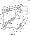
Owned storage module Referring specifically to FIGS. 1 and 2, the features and drawings of the present invention in one embodiment are a non-peripheral device with ownership shown in a perspective view, ie, a processing control unit based on a non-peripheral device. 2 (hereinafter referred to as processing control unit 2). In its simplest form, the
図1および2は完全に組み立てられた状態にある処理制御ユニット2を示し、ここでは処理制御ユニット2の主な部品の多くが示されている。説明するように、処理制御ユニット2は収納モジュール10を含み、この収納モジュール自身は図3により完全に示されているような、かなり特徴のあるユニークな支持構造体および幾何学的構造を有する。一実施例および好ましい実施例では、この収納モジュール10はメインサポートシャーシ14と、第1インサート66と、第2インサート70と、第3インサート74(図示せず)と、ダイナミックな背面34(図示せず)と、第1エンドプレート38と、第2エンドプレート42(図示せず)と、第1エンドキャップ46と、第2エンドキャップ50とを備え、1つ以上の処理部品およびその他のコンピュータ部品、例えばプリント回路基板、処理チップおよびそれらの内部に配置された回路のための密閉されたハウジング、すなわち収納体を提供している。
1 and 2 show the
図3および4はメインサポートシャーシ14およびこのメインサポートシャーシ14に取り付けまたは結合されるようになっている収納モジュール10の部品の一部の実施例を示す。これら部品は図示するように、取り外し自在にメインシャーシ14に結合され、本明細書に説明するように、処理制御ユニット2のユニークな特徴および機能を可能にするようになっていることが好ましい。メインサポートシャーシ14は収納モジュール10および処理制御ユニット2のための第1サポート構造体として働く。その小さい寸法および所有権のある構造によって、従来技術の設計で見られなかった利点が得られている。基本的には、メインサポートシャーシ14は任意の追加的物理的アタチメント、処理部品およびその他の回路基板部品を含む処理制御ユニット2の部品に対する構造的支持体となるだけでなく、処理制御ユニット2を任意のタイプの環境に適合できるようにすること、例えば任意の公知の構造体またはシステムに組み込みできるようにしたり、クラスター状およびマルチ環境で使用できるようにしている。
3 and 4 show an embodiment of a
特に図面の各々に示されるように、処理制御ユニット2および特に収納モジュール10は、基本的にはキューブ(立法)状の構造から成り、この構造ではメインサポートシャーシ14のうちの第1壁サポート18、第2壁サポート22および第3壁サポート26が、取り付けられたときのダイナミックな背面34と共に収納モジュール10の4つの側面を構成し、この場合、収納モジュール10の各コーナーに1つの合体モジュール54が位置する。
As particularly shown in each of the drawings, the
接合センター54は第1壁サポート18と、第2壁サポート22と、第3壁サポート26とを一体に接合するだけでなく、ベースを提供するように機能し、このベースには下記のエンドプレートを取り付けできる。取り付け受け部90内へ挿入される取り付け手段を使ってメインサポートシャーシ14にエンドプレートが結合される。取り付け受け部は図3ではアパーチャとして示されており、使用する取り付け手段の特定のタイプに応じてこのアパーチャにネジ切りしてもいし、しなくてもよい。接合センター54は更に下記のように処理制御ユニット2内に存在する所有権のあるプリント基板構造に対するメインサポートおよび接合センターとなっている。図3に示されるように、1つ以上のチャンネル状基板受け部62内にプリント回路基板を挿入し、固定することができる。図3に示し、本明細書に説明する特定の構造は、処理制御ユニット2内にプリント回路基板を固定し、係合するための一実施例または手段の一例にすぎない。当業者であれば認識できるように、その他の構造、組立体または装置を想到し、使用することができよう。例えば処理部品を固定するための手段として、ネジ、リベット、縛り嵌めおよびその他の一般に知られているものが挙げられる。
The joining
メインサポートシャーシ14は更に1つ以上のインサート部材上に位置する対応するインサートを受けるようになっている複数のスライド受け部82、ダイナミックな背面または2つ以上の処理制御ユニットを一体に結合するか、または処理制御ユニットを別の構造体、例えばテンペスト(Tempest)スーパー構造体内に組み込みできるようにするのに使用されるあるタイプの取り付けブラケットを更に含む。スライド受け部82は構造体の適当な要素または構造体、もしくはデバイス自身を取り込むか、または受けるのにも使用でき、この場合、処理制御ユニットおよび特に収納モジュールは負荷支持部材として働く。処理制御ユニット2が負荷支持部材として機能できる能力は、そのユニークなシャーシ構造から得られる。例えば処理制御ユニット2は2つの構造体を一体に架橋し、かつ構造体の全体の構造的支持および安定性に寄与するように使用できる。更に、処理制御ユニット2はメインサポートシャーシ14に直接取り付けられた負荷を支持できる。例えば処理制御ユニット2によってコンピュータスクリーン、すなわちモニタ170を物理的に支持し、プロセス制御できる。別の例として種々の家庭用器具、例えば照明器具またはブレーカーボックスなどを物理的に支持し、プロセス制御するのに処理制御ユニット2を使用できる。更に、必要であれば、処理制御ユニット2に増設ヒートシンクアセンブリを同じように結合してもよい。その他の多くの可能な負荷支持状況または環境が可能であり、本発明においてこれらを考えつくことができる。従って、本明細書で特に引用するものは単に説明のためのものであり、発明をいかなる意味でも限定するものではない。スライド受け部82はメインサポートシャーシ14の接合センター54の長さにわたって走行する実質的に円筒形のチャンネルとして示されている。これらスライド受け部82は外部部品をメインサポートシャーシ14に結合する1つの手段しか含んでいない。当業者が認識するように、上記のような種々の部品を取り付けるための手段を提供する意図する機能を実施するのに、その他の構造または組立体も可能であり、これらを使用することができる。
The
図3および4はメインサポートシャーシ14および特に第1壁サポート18、第2壁サポート22および第3壁サポート26の凹状の性質を更に示す。第1インサート部材66、第2インサート部材70および第3インサート部材74は対応する凹状構造を構成している。これら部品の各々は第1壁サポート18が第1インサート16内に対して設計された一致する曲率半径に対応するような曲率半径20を有するように、特別に計算された曲率半径を更に有する。同様に、第2壁サポート22は第2インサート70に対して設計された一致する曲率半径に対応するような曲率半径24を有し、第3壁サポート26は第3インサート74に対して設計された一致する曲率半径に対応するような曲率半径28を有する。図5および6に示されるように、エンドプレート38および42のみならず、エンドキャップ46および50の各々は、メインサポートシャーシ14の凹状構造プロフィルに一致するような同様な構造プロフィルを有する。これら図に示された実施例では、壁サポートは約7.2cm(約2.8インチ)の曲率半径を有し、インサート部材は約6.9cm(約2.7インチ)の曲率半径を有する。凹状構造および計算された曲率の各々はメインサポートシャーシ14の構造全体の剛性および強度に寄与するだけでなく、処理制御ユニット2の熱力学的熱放散特性にも寄与する。例えば後により詳細に説明する自然対流式冷却システムでは、この凹状構造は収納モジュール10の外側の、主に上のコーナーへの加熱された空気の分散を促進するので、熱または加熱された空気を処理制御ユニット2の内側部分の頂部および中心から上部左右のコーナーに向けて分散できこれらコーナーにおいて熱および加熱された空気は換気ポート98を通って逃れたり、またはこれらコーナーにおいて収納モジュール10の頂部を通って更に伝達できる。必要に応じて収納モジュール10の構造を最適にするためにこれら要素の曲率半径が互いに異なるような別の実施例を想到することができる。
3 and 4 further illustrate the concave nature of the
好ましい実施例では、メインサポートシャーシ14は処理制御ユニット2およびその内部に含まれる部品に対して極端に強力な支持構造体となるように設計され、そのような構造とされたフルメタルシャーシを含む。正常な状況および極端な状況でも、このメインサポートシャーシ14は種々の外部ソース、例えば従来のコンピュータ収納体を通常変形または抑止させるか、またはそれらの能力を他の環境または極端な環境で使用するように制限させるような外部ソースから生じる極めて大きい印加衝撃力に耐えることができる。基本的には、メインサポートシャーシ14は処理制御ユニット2に対する実質的に破壊不能なコンピュータ収納体を提供する主な寄与部材となっている。コンピュータ収納体のこのようなユニークな特徴は、幾何学的形状、これら部品が一体に適合している方法、それらの材料の組成およびその他の要因、例えば材料の厚みを含む、収納モジュール10を製造するのに使用されている部品の特定のデザインに直接関連している。特に収納モジュール10は完全にアール状に製造することが好ましく、存在するほとんどどの特徴部および要素もアールを含む。このようなアールの原理は処理制御ユニット2に加えられる負荷が処理制御ユニット2の外側エッジに伝えられるように機能するのに使用されている。従って、収納モジュール10の頂部に負荷または圧力が加えられた場合、その負荷は側面に沿って頂部およびベースに伝えられ、かつ実質的に収納モジュール10のコーナーへ伝えられる。基本的には、加えられたすべての負荷は最大強度が集中している処理制御ユニット2のコーナーへ伝えられる。
In the preferred embodiment, the
処理制御ユニット2およびその部品、すなわち収納モジュール10、メインサポートシャーシ14、インサート66、70および74、ダイナミックな背面34およびエンドプレート38、42の各々は、押し出しプロセスを使って金属から製造することが好ましい。一実施例では、メインサポートシャーシ14、第1インサート66、第2インサート70および第3インサート74、ダイナミックな背面34および第1エンドプレート38および第2エンドプレート42は、収納モジュール10に強力で軽量の特性を与えるために高級アルミニウムから製造されている。更に金属ケーシングを使用することによって良好な熱伝達特性が得られている。アルミニウム、種々のグレードのアルミニウムおよび/またはアルミ複合材料から製造することが好ましいが、ユーザーの特定のニーズおよび/または要求に応じて他の種々の金属、チタン、銅、マグネシウム、新しく得られたハイブリッド金属合金、スチールおよび他の金属、ならびに金属合金だけでなく、プラスチック、グラファイト、複合体、ナイロンまたはこれらの組み合わせを使用し、収納モジュール10の主要部品を製造できる。基本的には処理制御ユニットのための意図する環境または処理制御ユニットの使用は、製造される部品の特定の材料の組成を大きく決定する。説明するように、本発明の重要な特徴は、種々の異なる、および/または極端な環境内において、種々の用途に対し、処理制御ユニットを適合し、使用できる能力にある。このように、処理制御ユニットの特定の設計は適当な材料を利用しようとする努力に応じて決まる。表現を変えれば、本発明の処理制御ユニットは意図する用途に鑑み、ニーズを最良に満たす所定の特別に識別された材料組成を使用しようとするものである。例えば液体冷却式モデルまたは構造では処理制御ユニットに対する絶縁特性をより大きくするのに、チタンのようなより密な材料を使用できる
Each of the
好ましいアルミニウムの組成を仮定した場合、収納モジュール10は極めて強力で軽量となり、移動が容易であるので、エンドユーザーおよびメーカーの双方に対して大きな利点を提供できる。例えばエンドユーザーの見地から、従来の関連するコンピュータを使用できないような種々の環境内での使用に適す。更にエンドユーザーは基本的には見かけをよりすっきりとし、あまり散らかっていない部屋にし、またはより美的に魅力のあるワークステーションを提供するよう、基本的には処理制御ユニット2を隠したり、マスクしたり、カモフラージュしたりすることができる。
Given the preferred aluminum composition, the
製造の見地から、収納モジュール10および処理制御ユニット2は1つ以上の自動化された組み立てプロセス、例えば上記のような部品の各々を設置し、または組み立てるための自動化されたロボットプロセスと結合された自動化されたアルミ押し出しプロセスを使って製造できる。押し出しプロセスおよびロボット組み立てプロセスを適用できる結果、収納モジュール10を迅速に大量生産できることも同じように有利である。当然ながら、処理制御ユニットの特定の用途および所望する特定の特性に応じて、他の公知の方法、例えばダイキャストおよび射出成形、手による組み立てを使って処理制御ユニット2を製造することもできる。
From a manufacturing standpoint, the
更に収納モジュール10はサイズが小さく、比較的軽量であるので、出荷コストだけでなく製造コストも大幅に低減される。
Furthermore, since the
図4を参照すると、ここには収納モジュール10の主要部品、すなわちメインサポートシャーシ14の側面に取り外し自在に取り付けまたは結合されるようになっているいくつかのインサートおよびメインサポートシャーシ14が示されている。図4はメインサポートシャーシ14の後部部分に取り外し自在に取り付けまたは結合されるようになっているダイナミックな背面34も示す。
Referring now to FIG. 4, there are shown a number of inserts and
特に第1壁サポート18に第1インサート66が取り付けられており、第2壁サポート22には第2インサート70が取り付けられており、第3壁サポート26には第3インサート74が取り付けられている。更に第1インサート66、第2インサート70および第3インサート74、ならびに第1壁サポート18、第2壁サポート22および第3壁サポート26の各々は実質的にこれらを入れ子状に、一体に嵌合できるよう、ほぼ同じ曲率半径を有する。
In particular, a
第1インサート66、第2インサート70および第3インサート74の各々はメインサポートシャーシ14を結合するための手段を構成する。図4に示された一実施例では、各インサートはインサートの両端部に位置する2つのインサート係合部材78を含み、これら係合部材78はメインサポートシャーシ14内に形成された外部部材に係合またはこれを結合するための手段内に嵌合されるようになっている。図示された実施例では、この外部部材係合手段は図3に示され、かつ上記のようなメインサポートシャーシ14に沿って位置する複数のスライド受け部82を含む。その他の手段、例えばスナップ、ネジ、リベット、連結システムおよび当技術分野で一般に知られるその他の手段を含む種々のアタッチメントを利用する他の手段も使用が可能である。
Each of the
ダイナミックな背面34はメインサポートシャーシ14を解放自在に結合するようにもなっており、かつこのように結合できる。ダイナミックな背面34はメインサポートシャーシ14を係合するための手段を含む。図示された実施例では、この係合手段はダイナミックな背面34の両端に位置する2つの係合部材86から構成されている。これら係合部材86はインサート66、70および74がそれぞれの位置においてメインサポートシャーシ14に取り付けられているのと同じように、ダイナミックな背面34をメインサポートシャーシ14に取り外し自在に取り付けるよう、メインサポートシャーシ14の後部部分に沿ったそれぞれの位置(スペース30として示されている)にてスライド受け部82内に嵌合している。これら特定の特徴はいくつかの可能な構成、構造または組み立てのうちの1つとして意図したものである。従って、当業者であれば、図面に特別に示し、本明細書で説明したものと異なる、ダイナミックな背面34をメインサポートシャーシ14に取り付けるのに利用できる別の手段も想到できよう。
The
外部部材を係合するための手段および特にスライド受け部82は、種々のタイプの外部部材、例えばインサート66、70および74、ダイナミックな背面34、取り付けブラケット、別の制御処理ユニットまたは他の必要なデバイス、構造体またはアセンブリを解放自在に結合できる。図4に示されるように、スライド受け部82は各インサートを必要に応じて内外にスライドできるよう、対応する結合部材78に解放自在に係合する。上記のように、本発明ではメインサポートシャーシ14を結合するための他の手段および外部部材を結合するための他の手段も使用でき、これら手段は当業者には明らかとなろう。
Means for engaging the outer member and in particular the
各インサートおよびダイナミックな背面34をメインサポートシャーシ14に取り外し自在に、すなわち解放自在に結合できるようにすることにより、従来の関連するコンピュータ収納体よりも大きな、いくつかの処理制御ユニット2の利点が得られる。例えば限定する意図は全くないが、第1インサート66、第2インサート70および第3インサート74を美的な観点から除去したり、置換したり、または交換してもよい。これらインサート部材は異なるカラーおよび/またはテクスチャーを有することができるので、処理制御ユニット2を特定の好みに合わせたり、または所定の環境または設定により適合できるようにカスタム化することができる。更に各エンドユーザーが特定のユニットの外観および全体の感じを指定できるようにすることによって、より大きな汎用性が得られる。取り外し自在な、または相互交換可能なインサート部材は、任意の会社エンティティまたはユニットを使用する個人に対して(例えばロゴまたは商標を付けることにより)処理制御ユニット2をブランド化する能力も提供できる。これら部材がメインサポートシャーシ14の外側にあるので、インサート部材は必要な形態またはブランドをとることができる。
By allowing each insert and dynamic back 34 to be removably or releasably coupled to the
美的な観点とは別に、その他の利点も認識される。より高いレベルの汎用性では、外部部材に係合するための手段は処理制御ユニット2に、ロバストで、かつカスタム化できる能力を提供する。すなわち処理制御ユニット2をモバイル設定または所有権のあるドッキングステーションにドッキングでき、このドッキングステーションで処理制御ユニットは任意の考えつくことができる物体、例えばボート、自動車、飛行機およびこれまで処理制御ユニットを含むことができなかったその他のアイテムまたはデバイスに対する制御ユニットとして働くことができる。これらの場所はこれまではそのようにすることが困難または現実的ではなかった場所である。
Apart from the aesthetic point of view, other benefits are also recognized. At a higher level of versatility, the means for engaging the external member provides the
図5を参照すると、ここにはメインサポートシャーシ14の第1端部部分40および第2端部部分44にそれぞれ結合し、処理制御ユニット2の内部の内外に空気を流入または流出させることができるようにするための手段を提供するように機能する、第1エンドプレート38または第2エンドプレート32の1つの図が示されている。第1エンドプレート38および第2エンドプレート42は(図6に示される)第1エンドキャップ46、第2エンドキャップ50と共にそれぞれ機能し、収納モジュール10に対する保護機能カバーとなっている。第1エンドプレート38および第2エンドプレート42は(図1に示されるような)取り付け手段110を使って、メインサポートシャーシ1414に取り付けられており、この取り付け手段110としては、一般に種々のタイプのネジ、リベットまたは当技術分野で一般に知られているその他の締結具を挙げることができるが、当技術分野で一般に知られているように、メインサポートシャーシ14に対し、第1エンドキャップ46および第2エンドキャップ50と共に、第1エンドプレート38および第2エンドプレート42を取り付けるためのその他のシステムおよび装置を挙げることもできる。一実施例では、この取り付け手段110はメインサポートシャーシ14の4つのコーナーにおいて、合体モジュール54内に位置するそれぞれの取り付け受け部90(図3には取り付け受け部90および合体モジュール54が示されている)に嵌合できるネジを含む。
Referring to FIG. 5, it is coupled to the
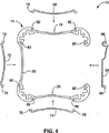
第1エンドプレート38および第2エンドプレート42は構造的にはメインサポートシャーシ14の端部部分40および44に整合するような幾何学的形状および構造を含む。特に図5に示されるように、第1エンドプレート38および第2エンドプレート42の周辺プロフィルは一連の凹状エッジを含み、各エッジはそれぞれの壁サポートおよびダイナミックな背面の曲率半径に一致するような曲率半径を有する。基本的には、エンドプレート38および42は、収納モジュール10の形状がどんなものであれ、その形状に一致することにより、収納モジュール10の端部を閉じるように働く。
The
第1エンドプレート38および第2エンドプレート42の主な機能の1つは、収納モジュール10に対する空気の流入および流出を容易にするか、または可能にするための手段を提供することにある。図5に示されるような実施例では、かかる手段はエンドプレート38および42の表面に沿って間欠的に離間し、これらプレートを貫通する複数のアパーチャ、すなわち換気ポート98を含む。下記の熱力学の章で説明するように、一実施例ではコンピュータ処理センター2は内部に収納された処理部品を冷却するのに自然対流を利用している。エンドプレート38および42に換気ポート98を設けたことにより、周辺空気は処理制御ユニット2の内部に進入することができ、他方、プロセッサおよび処理制御ユニット2内にある他の部品から生じた加熱された空気は、内部から外部環境へ流出できる。このような自然の物理現象により、加熱された空気は上昇し、より低温の空気が収納モジュール10に吸引されるにつれ、加熱された空気は収納モジュール10から強制的に排出される。周辺空気のこのような流入および加熱された空気の流出によって、処理制御ユニット2は自然の対流冷却系を利用して、処理制御ユニット2内で機能または作動するプロセッサおよびその他の内部部品を冷却できる。換気ポート98は多数あり、エンドプレート38および42の表面積の大部分、特に外側周辺領域に広がり、空気冷却式モデル内の内部部品の冷却を高め、かつ効率的にできることが好ましい。換気ポート98は空気流を最適にし、収納モジュール10への部分流れを制限するように、正確な仕様となるように機械加工されている。一部の流れを制限することにより、ゴミおよびその他のほこりまたは粒子が収納モジュール10の内部に進入することが防止できる。モジュール10内にこれらほこりが入った場合、処理制御ユニット2を破壊したり、または性能を低下させることがある。換気ポート98は空気粒子しか通過できないようなサイズとされている。
One of the main functions of the
収納モジュール10は金属製であることが好ましいので、収納体にほこりおよびその他の粒子またはゴミが付着するのを防止するように、構造全体またはその一部を正または負に帯電させることができる。かかる静電電荷は静電電荷がほこりまたはその他の要素をジャンプし、メインボードを破損する可能性も防止できる。静電電荷を設けることは単に逆のイオンフィルタリングすることと同様である。収納モジュール10を負に帯電させることにより、すべての正に帯電したイオン(すなわちほこり、ゴミなど)が反撥される。
Since the
図6は第1エンドキャップ46および第2エンドキャップ50を示し、これらキャップは第1エンドプレート38および第2エンドプレート42にそれぞれフィットするだけでなく、メインサポートシャーシ14の各端部部分40および44にもフィットするようになっている。これらエンドキャップはあるタイプの衝撃吸収プラスチックまたはゴムから製造し、処理制御ユニット2の保護ワイヤーとなるだけでなく、全体の外観および感じをよくするようにも働く。
FIG. 6 shows a
好ましい一実施例では、処理制御ユニット2は従来のコンピュータ収納体と比較してかなり狭い設置面積、すなわちサイズを有する。例えば一実施例では、その幾何学的寸法は長さが約9.1cm(約3.6インチ)であり、幅が約9.1cm(3.6インチ)であり、高さが約9.1cm(3.6インチ)であり、これら寸法は従来の関連する処理制御ユニット、例えばデスクトップコンピュータまたはほとんどのポータブルコンピュータ、すなわちラップトップよりもかなり小さい。寸法上小さくなっている特徴の外に、処理制御ユニット2はかなりユニークな幾何学的特徴も有する。図1および2はこのユニークな形状、すなわち幾何学的形状を示しており、これら形状のほとんどは既に説明したとおりである。これら寸法および幾何学的特徴は、形態に所有権があり、各特徴は処理制御ユニット2の特定のユニークな機能上の特徴および性能に寄与している。更にこれら特徴は、従来の関連する処理制御ユニットには見られなかった大きな特性および利点も提供している。言い換えれば、本明細書に記載し、図示したような処理制御ユニット2の所有権のある設計によって、このユニットは、従来の関連するコンピュータ収納体および処理ユニットでは不可能であった態様および環境でも作動できる。
In a preferred embodiment, the
処理制御ユニット2は任意のサイズおよび/または幾何学的形状をとることができることを指摘することが重要である。好ましい実施例では、処理制御ユニット2は約9.1cm×9.1cm×9.1cm(3.6×3.6×3.6)サイズの実質的にキューブ(立方)形状となっているが、本発明の範囲では他の寸法および形状も可能である。特に本明細書で述べたように、この処理制御ユニットは当業者が想到できるような種々の構造またはスーパー構造での使用にも適合できる。このような意味において、処理制御ユニット2は使用する環境の物理的属性をとることができるような適当な寸法および構造を含むことができなければならない。例えば処理制御ユニットを薄いハンドヘルド装置内で使用しなければならない場合、このユニットは薄いプロフィルの物理構造を有するように製造されるので、好ましい実施例のキューブ(立方体)形状とは異なったものとなる。このように処理制御ユニット2内で使用される種々のコンピュータおよび処理部品は関連するサイズ、形状および構造となることもできる。
It is important to point out that the
処理制御ユニット2はそのサイズから明らかなように、一般に従来のコンピュータ収納体、例えばデスクトップパソコンまたはラップトップパソコンで一般に見られるような周辺部品を全く含まない。従って、「非周辺機器に基づく」なるフレーズが使用されている。処理制御ユニット2は所有権のある非周辺機器構造を有し、この場合「周辺」なる用語は従来技術で一般に公知の、かつ従来のコンピュータ収納体に一般に収納されるようないくつかのタイプの現在の部品のうちの1つまたは全てを有する。周辺デバイスは処理制御ユニット2にプロセス結合することが好ましいが、ユニットの構成には物理的に含まれないことが好ましい。本明細書に説明した方法を使って、例えばスライドオンシステムまたはスナップオンシステムを使って周辺デバイスを取り付けたり、結合したりできる。しかしながら、明らかに所望する場合、処理制御ユニット2は従来技術で見られるような従来の周辺デバイス、例えばハードディスクドライブ、CD−ROMドライブ、メモリ記憶デバイスなどを含むように設計できる。従って、本発明は非周辺構造だけに限定されるものではない。
As is apparent from its size, the
最も一般的なタイプの周辺デバイスまたは部品の一部は大量記憶デバイスまたはメディア記憶デバイス、例えばハードディスクドライブ、磁気ディスクドライブ、磁気カセットドライブおよび光ディスクドライブ(例えばハードドライブ、フロッピー(登録商標)ディスクドライブ、CD−ROMドライブ、DVDドライブ、Zipドライブなど)である。これら全てのタイプの周辺デバイスは部品であるが、実際には収納モジュール10および処理制御ユニット2によって物理的にサポートされているわけではなく、これらの内部に物理的に存在しているだけであり、これら周辺デバイスまたは部品は設計するように処理制御ユニット2とコンパーチブルであり、機能し、および/または作動するようになっている。これら上記デバイスは一般に周辺機器と見なされることに留意すべきである。しかしながら、これらアイテムは処理制御ユニット2のプリント回路基板構造に一体化したり、または組み込むこともできる。この場合、制御ユニットにおいて、これらアイテムは周辺機器を含まないか、または周辺機器と見なされるが、その代わりに処理制御ユニット2のプリント回路基板構造のロジックの一部となる。
Some of the most common types of peripheral devices or parts are mass storage devices or media storage devices such as hard disk drives, magnetic disk drives, magnetic cassette drives and optical disk drives (eg hard drives, floppy disk drives, CDs) -ROM drive, DVD drive, Zip drive, etc.). All these types of peripheral devices are components, but in reality they are not physically supported by the
処理制御ユニット2は上記のように内部周辺デバイスを含まないことが好ましいが、内部アーキテクチャの一部としてシステムバスを含むことが好ましい。このシステムバスは当技術分野で一般に知られているように機能するようになっており、種々の外部部品またはこのシステムバスがない場合に内部のものとなる周辺デバイスを接続し、これらを作動可能にするように構成されている。システムバスはこれら部品と、処理制御ユニット2の処理部品との間でデータを交換できるようにもする。
The
システムバスは、メモリバスまたはメモリコントローラ、周辺バスまたは種々のバスアーキテクチャのうちの任意の1つを使用するローカルバスを含む種々のバス構造体の1つを含むことができる。システムバスによって接続される代表的な部品として、処理システムおよびメモリがある。その他の部品は、1つ以上の大量記憶デバイスインターフェース、1つ以上の入力インターフェース、1つ以上の出力インターフェースおよび/または1つ以上のネットワークインターフェースを含むことができる。 The system bus may include one of a variety of bus structures including a memory bus or memory controller, a peripheral bus, or a local bus using any one of a variety of bus architectures. Typical components connected by the system bus include a processing system and a memory. Other components can include one or more mass storage device interfaces, one or more input interfaces, one or more output interfaces, and / or one or more network interfaces.
処理制御ユニット2は従来の関連するコンピュータシステムよりも性能が優れているが、少なくともこれらシステムと同じように機能するようになっている。従って、ユーザーが代表的な、または公知のコンピュータシステム(例えばデスクトップ計算システム)で行うことができることは、すべて本発明のコンピュータシステムで行うことができる。実際的な見地から、このことは機能または作動が犠牲になることはなく、多くのことが得られることを意味する。このように、本明細書で説明した所有権のある設計をこのように使用できるようにするためには、処理制御ユニット2は従来の関連するコンピュータまたはコンピュータプロセッサと同様なタスクを実行できるだけでなく、かかるタスクを実行するのに必要なこれら部品にアクセスしたり、これら部品を利用できなければならない。
The
計算ユニットとして機能するために処理制御ユニット2は種々の識別されあ周辺機器およびその他のハードウェア部品を接続するための必要な手段を含むが、これら部品は収納モジュール10を用いることなく位置することが好ましいか、またはこれら収納モジュール10から離間していることが好ましい。従って、本発明の処理制御ユニット2は各周辺デバイスと処理制御ユニット2内に含まれる処理部品との間の必要なリンクを行うための種々の接続手段を含む。例えば処理制御ユニット2のシステムバスに1つ以上の大量記憶デバイスを接続するのに、1つ以上の大量記憶デバイスインターフェースを使用できる。これら大量記憶デバイスは処理制御ユニット2の周辺機器であるが、制御ユニットが大量のデータを保持できるようにする。上記のように、大量記憶デバイスの例としてはハードディスクドライブ、磁気ディスクドライブ、テープドライブおよび光ディスクドライブを挙げることができる。大量記憶デバイスは磁気ハードディスク、取り外し自在な磁気ディスク、磁気カセット、光ディスクまたは別のコンピュータで読み取り可能な媒体との間で読み出し/書き込みを行うことができる。これら大量記憶デバイスおよびそれらに対応するコンピュータで読み取り可能な媒体は、1つ以上のプログラムモジュール、例えばオペレーティングシステム、1つ以上のアプリケーションプログラム、その他のプログラムモジュール、またはプログラムデータを含むことができるデータおよび/または実行可能な命令を不揮発記憶できる。
In order to function as a computing unit, the
ユーザーが1つ以上の対応する入力デバイスを通して処理制御ユニット10内にデータおよび/または命令を入力できるようにするために、1つ以上の入力インターフェースを使用することもできる。かかる入力デバイスの例として、キーボードおよび別の入力デバイス、例えばマウス、トラックボール、ライトペン、スタイラスまたはその他のポインティングデバイス、マイク、ジョイスティック、ゲームパッド、衛星ディッシュ、スキャナ、ビデオカメラ、デジタルカメラなどを挙げることができる。同様に、システムバスに入力デバイスを接続するのに使用できる入力インターフェースの例として、シリアルポート、パラレルポート、ゲームポート、ユニバーサルシリアルバス(USB)、ファイヤーワイヤー(IEEE1394)または別のインターフェースを挙げることができる。
One or more input interfaces may also be used to allow a user to enter data and / or instructions into the
システムバスに1つ以上の対応する入力デバイスを接続するのに、1つ以上の出力インターフェースを使用することもできる。この出力デバイスの例として、モニタまたはディスプレイスクリーン、スピーカーシステム、プリンタなどを挙げることができる。これら特定の出力デバイスも処理制御ユニット2(を用いない)周辺機器である。出力インターフェースの例としてビデオアダプタ、オーディオアダプタ、パラレルポートなどを挙げることができる。 One or more output interfaces can also be used to connect one or more corresponding input devices to the system bus. Examples of the output device include a monitor or display screen, a speaker system, a printer, and the like. These specific output devices are also peripheral devices of the processing control unit 2 (not using). Examples of the output interface include a video adapter, an audio adapter, and a parallel port.
別の実施例では、インターフェースを使用することなく、システムバスに使用される任意の周辺デバイスが直接接続される。この実施例は「ダイナミックにモジュラー式の処理ユニットを提供するためのシステムおよび方法」を発明の名称とし、2003年10月22日に出願された継続中の米国特許出願第 号に完全に記載されており、この出願全体を本明細書で参考例として援用する。 In another embodiment, any peripheral device used for the system bus is directly connected without using an interface. This embodiment is entitled “System and Method for Providing Dynamic Modular Processing Units” and is fully described in the pending US patent application filed on Oct. 22, 2003. This entire application is incorporated herein by reference.
非周辺コンピュータシステムを提供すると、ユーザーに対し、より大きい周辺のパックされたコンピュータユニットよりも多数の利点を与えることができる。これら利点の一部はユーザーがコンピュータユニットおよびシステムを収納するのに必要なスペースを小さくできることである。本発明の処理制御ユニットは直接デスク上にセットできるし、または視界から完全に隠すこともできる。潜在的な保管一は無限である。処理制御ユニット2は、これを視界から隠すために、あるタイプのデスクトップ部分、例えば時計内にカモフラージュすることさえもできる。その他の特徴として、ノイズおよび発生する熱を比較的低減できること、またはインテリジェンスもしくはスマート技術を種々のアイテム、アセンブリまたはシステムに導入するためのユニバーサルアプリケーションを挙げることができる。これらおよびそれ以外の例は、本明細書から明らかである。
Providing a non-peripheral computer system can provide a user with a number of advantages over a larger peripheral packed computer unit. Some of these advantages are that the user can reduce the space required to house the computer unit and system. The process control unit of the present invention can be set directly on the desk or completely hidden from view. The potential storage one is endless. The
上記のように、本発明にかかわる処理制御ユニット2は多数の理由から収納モジュール10の外側の所定のメインストリーム部品を有するように設計されている。第1に、その小さいサイズのために、処理制御ユニット2を種々のデバイス、システム、車両またはアセンブリに組み込み、必要に応じてこれらを強化することができることである。一般的な周辺デバイス、例えば特殊なディスプレイ、キーボードなどを従来のコンピュータワークステーションで使用することができるが、この処理制御ユニット2は周辺機器がなくてもよく、多くのアイテム、システムなどのための制御ユニットとなるようにカスタム化できる。換言すれば、この処理制御ユニット2を使用して任意のタイプの考えつくことができる制御アイテム内にスマート技術を導入できる。
As described above, the
第2は、冷却問題に関するものであり、コンピュータの内部で発生する熱のほとんどは2つの場所、すなわちコンピュータプロセッサとハードドライブから生じる。収納モジュール10からハードドライブを除き、これを処理制御ユニット2の外部の自らの収納体に入れることにより、より良好で、かつより効率的な冷却を行うことができる。システムの冷却特性を改善することによりプロセッサ自身の寿命を長くすることができるので、コンピュータ全体の寿命も長くすることができる。
The second is related to cooling problems, where most of the heat generated inside the computer comes from two places: the computer processor and the hard drive. By removing the hard drive from the
第3に、処理制御ユニット2はアイソレートされた電源を含むことが好ましい。他の周辺機器から電源をアイソレートすることにより、システム内に存在する1つ以上の周辺部品、例えばハードドライブおよび/またはCD−ROMの外に、プロセッサに給電するのに同じ電圧を使って処理のために供給される電圧の多くを使用できる。ワークステーションモデルでは処理制御ユニット2がなくても、周辺部品が存在するが、この周辺部品にはモニタ電源によって給電することが好ましい。
Third, the
第4に、処理制御ユニット2がオンかオフであるか、またはディスクが作動しているかどうかを示すのにライトまたは他のインジケータを使用しないことが望ましい。作動および電源ライトを使用してもよいが、これらはモニタまたは他の周辺ハウジングデバイスに設けることが好ましい。ライトが見えないか、またはライトが使用されない多くのアプリケーション、またはライトが破壊的、例えばダークルームおよびその他の光検出環境となるアプリケーションで、システムを使用しようとしている場合に、このタイプのデザインが好ましい。しかしながら、明らかに外部照明、例えば電源のオンまたはディスクの使用を示すための従来のコンピュータシステムで見られるような照明を、必要であれば実際の処理制御ユニット2内に実現したり、または組み込んでもよい。
Fourth, it is desirable not to use lights or other indicators to indicate whether the
第5に、あるタイプの機械式または強制的空気システム、例えばファンまたは他の任意の冷却部材もしくはシステムを必要とするのではなく、処理制御ユニットからの熱を放散させるのに受動式コーティングシステム、例えば自然対流システムを使用できる。当然ながら、かかる強制空気システムは必要であれば使用したり組み込んだりすることもできる。これら利点はすべて包括されるものではない。当業者であれば、それ以外の特徴および利点を認識できよう。 Fifth, a passive coating system to dissipate heat from the process control unit, rather than requiring some type of mechanical or forced air system, such as a fan or any other cooling member or system, For example, a natural convection system can be used. Of course, such a forced air system can be used and incorporated if desired. All of these benefits are not comprehensive. Those skilled in the art will recognize other features and advantages.
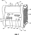
図7を参照すると、ここには処理制御ユニット2および特に収納モジュール2が示されており、このモジュールは第1エンドプレート38および第2エンドプレート42(図示せず)と、第1エンドキャップ46および第2エンドキャップ50と、インサート66、70(図示せず)および74(図示せず)のみならず、これに取り付けられたダイナミックな背面34とを有する、組み立てられた状態にある。ダイナミックな背面34は種々の入出力デバイスおよび電源コード処理制御ユニット2に結合し、特にワークステーション環境内でユニットを制御できるようにするのに使用されている、接続に必要なポートおよび関連する手段を含むようになっている。利用できる全てのタイプのポートが特別に図示され、かつ本明細書に記載されているわけではないが、将来存在する他の他の任意のタイプのポートと共に、現在のポートまたは性質上所有権のあるポートも処理制御ユニット2とコンパーチブルとなるようになっており、かつこれらポートを処理制御ユニット2内に組み込んだり、処理制御ユニットと共に機能するようになっている。このようなことは、必要に応じて異なるダイナミックな相互交換式背面34を設計することによって達成することが好ましい。
Referring to FIG. 7, there is shown a
特にダイナミックな背面34はDVIビデオポート120、10/100イーサネット(登録商標)ポート124、USBポート128および132、SATAバスポート136および140、パワーボタン144およびパワーポート148を含む。2つの処理制御ユニットを一体に電気的に結合し、システム全体の処理能力を高め、かつ本明細書に定めたようなスケールされた処理を提供するために使用される、所有権のあるユニバーサルポートも想到できる。当業者であれば、本発明の処理制御ユニットと共に利用できる種々のポートを認識することができよう。
Particularly
高度のダイナミックで、カスタム化可能で、相互交換可能な背面34は、周辺機器および垂直アプリケーションに対するサポートとなっている。図示された実施例では、背面34は収納体10に選択的に結合され、処理制御ユニット40をダイナミックにカスタム化できるようにする1つ以上の特徴部、インターフェース、機能、ロジックおよび/または部品を含むことができる。ダイナミックな背面34は2つ以上のモジュラー式処理ユニットを1つに電気的に説明し、上記のようなシステム全体の処理の雨量を高め、かつ以下に説明するようなスケーリングされた処理を提供する機能も含むことができる。
A highly dynamic, customizable,
当業者であれば、対応する特徴部、インターフェース、機能、ロジックおよび/または部品を有する背面34は代表的なものにすぎず、本発明の実施例は種々の異なる特徴部、インターフェース、機能および/または部品を有する背面を含むことが理解できよう。従って、1つの背面を別の背面に置換できるようにし、ユーザーが処理制御ユニット2のロジック、特徴および/または能力を選択的に変えることができるようにすることにより、処理制御ユニット2はダイナミックにカスタム化可能となっている。
For those skilled in the art, the
更に本発明の実施例は、種々の異なる寒極内で1つ以上のモジュラー式処理制御ユニットを使用できるように、任意の数および/またはタイプのロジックおよび/またはコネクタを含む。例えば一部の環境は車両(例えば自動車、トラック、オートバイなど)、油圧制御システム、構造的環境およびその他の環境を含むことができる。ダイナミック背面において、データ操作システムを変えることは、種々の環境に対して垂直および/または水平方向へのスケーリングを配慮したものである。 Further, embodiments of the present invention include any number and / or type of logic and / or connectors so that one or more modular processing control units can be used in a variety of different cold poles. For example, some environments can include vehicles (eg, automobiles, trucks, motorcycles, etc.), hydraulic control systems, structural environments, and other environments. In the dynamic backside, changing the data manipulation system allows for vertical and / or horizontal scaling for different environments.
一実施例では、収納モジュール10の構造および幾何学的形状は、これらポートのインターフェースに対する自然なくぼみを提供している。図7にはこのへこみが示されていることに留意すべきである。従って、これらポートはダイナミックな背面内に形成されたくぼみにより、これらポートが保護されているので、不意に落としても、または処理制御ユニット2および収納モジュール10にその他の衝撃が与えられてもシステムが破損することはない。第1エンドキャップ46および第2エンドキャップ50もシステムを破壊から保護するのを助けている。
In one embodiment, the structure and geometry of the
パワーボタン144は3つのステーと、すなわちシステムオン、システムオフおよびパワーブートのためのシステムスタンバイステートを有する。最初の2つのステーと、すなわちシステムオンおよびシステムオフは処理制御ユニット2の電源がオンとなっているか、またはオフとなっているかをそれぞれ定めている。システムスタンバイステートはそれらの中間ステートである。電源がオンにされ、電力を受けると、処理制御ユニット2にサポートされたオペレーティングシステムをロードし、ブートするように、システムに命令が出される。電源がオフにされると、次に処理制御ユニット2は進行中の処理を中断し、クイックシャットダウンシーケンスを開始し、その後、システムがパワーオンステートが附勢されるよう、まず不活動状態に入るスタンバイステートが続く。
The
好ましい実施例では、処理制御ユニット2はシステムをパワーアップするためのユニークなシステムまたはアセンブリも含む。このシステムは電源コードおよび対応するクリップをダイナミックな背面34に設けられた適当なポートにスナップ嵌合するとアクティブとなるようになっている。電源コードおよび対応するクリップを一旦パワーポート148にスナップ嵌合すると、システムは作動し、ブーとし始める。電源が一旦接続されると、電源コードが電源ポート148内のリード線に接続されていても、処理制御ユニット2はクリップが所定の場所にスナップ嵌合されるまで電源がオンとならないので、このクリップは重要である。電源コードが完全にスナップ嵌合されていないか、または正しく所定場所にスナップ嵌合されていないことをユーザーに警告または通知するインジケータをモニタに設けてもよい。
In the preferred embodiment, the
SATAバスポート136および140は記憶媒体周辺部品、例えばCD−ROMドライブおよびハードドライブを電子的に結合し、サポートするようになっている。
USBポート128および132はキーボード、マウスおよびその他の周辺部品、例えば56kモデム、タブレット、デジカメ、ネットワークカード、モニタおよびその他のような周辺部品を接続するようになっている。
本発明はスナップオン接続システムを介し、ダイナミックな背面にスナップ嵌合し、処理制御ユニット2のシステムバスに結合するようなスナップオン周辺機器も使用が可能である。既に述べたように、周辺機器または入出力デバイスを接続するためのその他のポートおよび手段を当業者が認識するように、処理制御ユニット2内に含め、組み込んでもよい。従って、本明細書で特別に説明した接続のための特定のポートおよび手段は単なる説明のためのものであり、発明を限定するものではない。
The present invention can also use snap-on peripherals that snap to the dynamic back and couple to the system bus of the
図8を参照すると、本発明にかかわる処理制御ユニット2は収納モジュール10と共に、所有権のあるコンピュータ処理システム150を備え、収納モジュール10は処理システム150および処理制御ユニット2内で作動し、機能するようになっているプリント回路基板を収納するためのユニークな構造および構造上の構成を含む。
Referring to FIG. 8, the
処理システム150は基本的には1つ以上のプリント回路基板、好ましくは図8に示されるように3基板構成152に配向され、形成された、好ましくは3つのプリント回路基板を含む。処理システム150および特に3基板構成152は第1プリント回路基板154と、第2プリント回路基板158と、第3プリント回路基板162とを備え、これら基板は図示するように収納モジュール10内に結合され、収納されている。処理システム150は更に少なくとも1つの中央プロセッサと、1つ以上の特定の機能またはタスクを実行するようになっているオプションの1つ以上のその他のプロセッサを含む。処理システム150は処理制御ユニット2の作動を実行するように機能し、特にコンピュータで読み取り可能な媒体、例えばメモリデバイス、磁気ハードディスク、取り外し自在な磁気ディスク、磁気カセット、光ディスク(例えばハードドライブ、CD−ROM、DVD、フロッピー(登録商標)ディスクなど)に設けられている命令、またはコンピュータで読み取り可能な媒体としても見なすことができる遠隔地の通信接続部からの命令を実行するように機能する。これらコンピュータで読み取り可能な媒体は処理制御ユニット2の外部または処理制御ユニット2を必要とすることなく設けられていることが好ましいが、処理システム150は一般に知られているようなかかるデバイス上の命令を制御し、実行するように機能するが、その差は、かかる実行がかかる周辺部品または入出力デバイスを処理制御ユニット2に電気的に接続するための1つ以上の手段を介して遠隔的に実行される点である。
The
電気プリント回路基板に係合し、またはこれらを結合し、またはこれらをサポートするための手段を使って、メインサポートシャーシ14内に第1電気プリント回路基板154、第2電気プリント回路基板158および第3電気プリント回路基板162がサポートされている。図8に示された実施例では、電気プリント回路基板に係合するための手段は収納モジュール10の各接合中心に設けられた一連の基板嵌合チャンネル62を備え、これら基板嵌合チャンネル62は電気プリント回路基板の端部部分162を受け入れるようになっている。収納モジュール10内に電気プリント回路基板を配置するためのいくつかの配置が存在し得るが、第1壁サポート18に隣接する基板嵌合チャンネル62内に第1電気プリント回路基板154の端部部分166が嵌合し、第2壁サポート22および第3壁サポート26に隣接する基板嵌合チャンネル62内に同様に第2電気プリント回路基板158および第3電気プリント回路基板162の端部部分166がそれぞれ嵌合し、図8に示されるような配置となることが好ましい。
The first electrical printed
3ボードメインボード構成152およびプリント回路基板はメインシャーシ14の壁サポートのいずれにもサポートされず、かつこの上に載らないことが好ましい。電気プリント回路基板の各々は特に接合センター内に位置する基板嵌合チャンネル62により、メインシャーシ14内に特に支持され、メインシャーシ14はこのように電気プリント回路基板の各々と対向する壁サポートとの間にギャップまたはスペースを設け、内部に提供されるユニークな自然の対流冷却特性に従って処理制御ユニット2内に適正な空気流を生じさせることができるようにしている。このように、各壁サポートに対して計算された各曲率半径は、このような制限を念頭に入れて設計されている。
The three-board mainboard configuration 152 and the printed circuit board are preferably not supported by, and do not rest on, any of the wall supports of the
3基板タイプのメイン基板構成152は従来の基板構成よりも大きな利点を与えている。1つの利点として、3基板構成152は従来のコンピュータシステムで見られるような1つのメイン基板の代わりに3つの多層基板として構成されていることが挙げられる。更にこれら基板は異なる平面に構成できるので、狭い不動産面積しか占めない。 The three-board type main board configuration 152 provides significant advantages over conventional board configurations. One advantage is that the three board configuration 152 is configured as three multilayer boards instead of one main board as found in conventional computer systems. Furthermore, these substrates can be configured in different planes and thus occupy only a small real estate area.
別の利点はメイン基板のうちの2つが第3のメイン基板に結合できることである。このように、第1電気プリント基板154、第2電気プリント回路基板158および第3電気プリント回路基板162の各々を一体に結合することにより、メインシャーシ14および収納モジュール10内の正しい場所からこれら基板の各々が外れる機会が大幅に少なくなっている。処理制御ユニット2がさらされる実質的にいかなる状況および条件または環境においても、3基板構成152は無傷であり、かつ作動秩序を維持するので、システムの完全性を維持できる。このことは衝撃および負荷が加えられる状況にも当てはまる。
Another advantage is that two of the main boards can be coupled to a third main board. In this manner, the first electric printed
製造中、および3基板構成152を収納モジュール10内に入れる前に、第3電気プリント回路基板158に第1電気プリント回路基板154および第3電気プリント回路基板162を取り付けることが好ましい。一旦3基板構成152を組み立てると、これら組立体を図示するようにメインサポートシャーシ14に挿入するように固定する。基板嵌合チャンネル62のすべてを必ずしも利用するわけではないことに留意すべきである。
The first electrical printed
図8は電気プリント回路基板のそれぞれの端部部分を支持するのに、これらチャンネルのうちの4つしか使用されていない好ましい実施例を示す。処理システム150に対する他の構造も可能である。例えば処理制御ユニット2が1つの基板だけを含んでもよいし、または2つ以上の基板を含んでもよい。更に処理システム150は層状の構造となっていてもよく、この場合、含まれるプリント回路基板は多数の平面構造で存在する。当業者であればいくつかの構造および可能性について認識できよう。
FIG. 8 shows a preferred embodiment in which only four of these channels are used to support respective end portions of the electrical printed circuit board. Other structures for the
上記多数の利点の他に、本発明はその他の重要な利点を特徴とする。そのうちの1つは、フル金属シャーシ、すなわちメインサポートシャーシ14を含む収納モジュール10に起因し、妨害電磁波(EMI)の形態をした電磁放射がほとんどまたは全くないことである。このことの大部分は、構造体の材料の特性、小さいサイズおよび厚み、並びに収納モジュール10の構造部品に対して処理部品が接近していることによるものである。処理部品から発生したどんなEMIも、収納モジュール10によって吸収されるので、処理部品の処理パワーは問題とならない。
In addition to the numerous advantages described above, the present invention features other important advantages. One of them is that there is little or no electromagnetic radiation in the form of electromagnetic interference (EMI) due to the
別の大きな利点は、収納モジュール10によって従来のコンピュータ収納形状よりもよりクリーンで、より減菌状態にできることである。収納モジュール10の構造により、特に小さいサイズおよび換気ポートおよび熱放散特性によってほこり粒子およびその他のタイプの異物が収納体に侵入することは極めて困難となっている。このことは収納体全体を収納できる液体冷却式モデルに特に当てはまる。種々のタイプの異物またゴミが処理制御ユニット2の部品を破壊したり、および/またはその性能を低下させ得る点で、内部がより減菌状態となっていることが重要である。
Another significant advantage is that the
処理制御ユニット2は、一実施例では自然対流に依存しているが、強制的な空気の流入はないので、自然の対流プロセス中の空気の自然な流入および流出が処理制御ユニット2へのほこり粒子または他のゴミの流入を大幅に減少させている。本明細書で説明する自然な対流冷却システムでは、自然の物理原理に従って収納モジュール10の内部に空気粒子が進入し、異物を運ぶ力は小さいので、空気粒子と共により重い異物を運ぶ傾向は小さくなる。このことは、ほとんどの環境が含むように、かかるより重い異物を含むような環境では有利である。
Although the
処理制御ユニット2のユニークな冷却方法によって、従来の関連する収納体を設置できなかった環境に、より適合できるようになっている。
The unique cooling method of the
本発明の処理制御ユニット2の更に別の利点は、その耐久性にある。コンパクトな構造およびアール状の構造のために、収納モジュール10は加えられる大きな衝撃力に耐えることができるので、処理制御ユニット2が考えられる任意のタイプの環境に適応できるようにする能力にも、この特徴が寄与している。収納モジュール10は電気回路の構造上の完全性にほとんど影響することなく、大小の衝撃力に耐えることができ、処理制御ユニット2の小さいサイズおよび携帯性として重要な利点によって、多くの想到可能な環境(この環境の一部は全く苛酷なものとなり得る)に適合できる。
Yet another advantage of the
極めて耐久性のある収納モジュール10の構造部品の外に、電気プリント回路基板および関連する回路も極めて耐久性がある。プリント回路基板を一旦挿入した後に、例えば収納体が落下したり、収納体に衝撃が加わることにより不適性な力が与えられる結果、プリント回路基板は除去することが極めて困難となる。更に基板は極めて軽量であるので、落下中に破壊するような十分大きい質量を有していない。しかしながら、明らかに収納体10は完全に破壊不能というわけではない。多くの状況では、収納モジュール10は基板構造よりも耐久性があるので、処理制御ユニット2の全体の耐久性は回路基板および内部の回路によって最も制限されやすい。
In addition to the structural parts of the highly
端的に述べれば、収納モジュール10は従来の関連する収納構造に見られなかった高レベルの耐久性を有する。これら収納構造体は破壊されるが、極めて小さい衝撃力または印加力によって破壊されることが多い。かかる破壊は本明細書に説明した処理制御ユニット2では生じない。
In short, the
収納モジュール10の耐久性は2つの主な特徴から生じている。まず第1に、収納モジュール10はアールをつけるように製造することが好ましい。各構造部品およびそれらの構造は1つ以上のアールを有する。アールに基づく構造体は、利用できる最強の構造の1つであるので、このことは収納モジュール10の強度を大幅に高めている。第2に、収納モジュール10の全体の形状は立方形状であるので、剛性をかなり大きくしている。この立法形状の剛性と組み合わされたアールに基づく構造部品は極めて耐久性があり、かつ機能的な収納体を提供する。
The durability of the
個々の処理ユニット/キューブの耐久性によって、本発明を使用しない場合に従来の技術では考えられなかったような位置で処理を行うことが可能となっている。例えばこれら処理ユニットを地中に埋めたり、水中に沈ませたり、海水中に沈ませたり、地中に何百メートル(何百フィート)も進入するドリルビットのヘッドに設置したり、不安定な表面に取り付けたり、現在の構造体に取り付けたり、家具内に設置したりでき、潜在的な処理位置は無限である。 Due to the durability of the individual processing units / cubes, it is possible to perform processing at a position that would not have been considered in the prior art when the present invention is not used. For example, these treatment units are buried in the ground, submerged in water, submerged in seawater, installed on the head of a drill bit that penetrates hundreds of meters (hundreds of feet), or unstable. It can be attached to a surface, attached to a current structure, or installed in furniture, with unlimited potential processing locations.
本発明の処理制御ユニットは、外部物体を取り付けるための手段および外部物体に係合するための手段(各手段はメインサポートシャーシ14の各壁サポートに存在するようなスライド受け部82を含むことが好ましい)を使って任意の構造体、デバイスまたはアセンブリに取り付けできる能力または取り付けられる能力を特徴とする。外部物体と処理制御ユニットとが作動的に接続されるように、任意の態様で処理制御ユニット2に係合できる能力を有する外部物体を本発明で保護するよう想到することができる。更に当業者であれば、収納モジュール10はスライド受け部82以外の外部物体に係合するための手段として別の構造を含むことができる。
The process control unit of the present invention may include means for attaching an external object and means for engaging the external object (each means including a
基本的には、どんな方法で達成するにせよ、処理制御ユニットに取り付けできる能力を提供する重要性は、本明細書で説明するような任意のタイプの環境内に処理制御ユニット2を統合できること、または種々のアイテムまたは物体(外部物体)を処理制御ユニット2に結合または取り付けできるようすることである。このユニットは種々の非活動的アイテム、例えばマルチプレックス処理センターまたは運搬車両に取り付けられるようになっているだけでなく、処理制御ユニットに直接取り付けられる種々の周辺機器、例えばモニタまたはLCDスクリーンを受けるようになっている。
Basically, the importance of providing the ability to be attached to a process control unit, whatever it is achieved, is that the
取り付け可能な特徴は、組み込みできる特徴であり、このことは処理制御ユニット2が構造部品内に直接組み込まれた外部物体に係合するための手段を含むことを意味する。独立した取り付けブラケット(すなわちホスト処理制御ユニットの接続部を完成するためのアダプタとして機能するブラケット)を使用した取り付けだけでなく、ホストへの直接の取り付け(すなわちカーステレオの代わりに自動社内にユニットを取り付けること)も本発明の保護対象である。
The attachable feature is a feature that can be incorporated, which means that the
処理制御ユニット2の別の能力は収納モジュールの更なる硬化を実行した場合に、テンペストスーパー構造体のようなスーパー構造体内に取り付け、実現できることである。かかる構造では、本明細書に説明するように、構造体内に処理制御ユニット2を取り付け、この処理制御ユニット2は構造体の部品または周辺部品をプロセス制御するように機能する。処理制御ユニット2は必要な場合に物理的構造体の負荷支持構造体としても機能する。異なるすべてのタイプのスーパー構造体を使用することも可能であり、このスーパー構造体は任意のタイプの材料、例えばプラスチック、木、金属合金および/またはかかる材料の複合体から製造できる。
Another capability of the
その他の利点は、ノイズおよび熱を低減でき、かつ種々の装置、例えば家具、固定具、車両、構造体、支持体、器具、機器、個人用アイテムなど(外部物体)にカスタム化可能なスマート技術を導入できることである。これら概念について、以下、詳細に説明する。 Another advantage is smart technology that can reduce noise and heat and can be customized to various devices such as furniture, fixtures, vehicles, structures, supports, instruments, equipment, personal items, etc. (external objects) Can be introduced. These concepts will be described in detail below.
カスタム化可能なロバストな計算システム
上記にヒントを与えたように、本発明の処理制御ユニットは次の点で従来の他の関連する計算処理システムと異なっている。すなわちそのユニークな形状および構造により、外部物体と関連させ、外部物体に組み込んだり、または他の方法で外部物体と作動可能に接続し、外部物体にカスタム化可能なスマート技術を導入し、よって本発明を使用しない場合に実行できなかった多くのスマートな機能を外部物体が実行できるようにしている。更にこのカスタム化可能なロバストな計算システムを種々のタイプの機能用アプリケーション、例えばコンピュータおよび計算システム、電子機器、家電、種々の業界のアプリケーションなどに適用できる。この章は、上記処理制御ユニットの能力を詳細に示し、かかるカスタム化可能なロバストな計算システムおよびいくつかのエンタプライズのアプリケーションにおけるシステムの適用可能性を示すものである。
Customizable Robust Computing System As hinted above, the processing control unit of the present invention differs from other related computing systems in the following respects. That is, due to its unique shape and structure, it introduces smart technology that can be associated with, incorporated into, or otherwise operatively connected to an external object, and customizable to the external object. It allows external objects to perform many smart functions that could not be performed if the invention was not used. Further, this customizable and robust computing system can be applied to various types of functional applications such as computers and computing systems, electronic equipment, consumer electronics, various industry applications, and the like. This section details the capabilities of the processing control unit, and shows the applicability of the system in such customizable and robust computing systems and in some enterprise applications.
本発明は考えられるシステム、デバイス、アセンブリ、装置または物体(以下、外部物体と総称する)へ所有権のある処理制御ユニットを統合、組み込み、またはその他の手段で作動的に接続し、この外部物体内にインテリジェンスを導入したり、または外部物体のための1つ以上の計算能力を実行し、または当業者が認識できるように外部物体に対するその他の機能を満たすことができる能力を特徴とする。このようにすることによって、アイテムは基本的にはスマートアイテムになる。すなわちスマートアイテムに変換される。このことは、外部物体がこれまで可能でなかった多くの機能およびタスクを実行できることを意味する。特に外部物体に対して処理制御ユニットを作動接続することにより、外部物体は現在存在する処理制御ユニットを用いない場合よりも、より機能的となることができる。例えば電子外部物体の場合、処理制御ユニットは電子外部物体の回路(存在する場合)と統合し、更なる計算および処理能力を提供できる。機械式アセンブリまたはデバイスまたはシステムに組み込んだ場合、処理制御ユニットが追加されることによるコンピュータにより機構を制御したり、またはより特別に制御したり、またはその他のいくつかの計算機能を可能にしたりすることができる。現在の構造体に組み込んだ場合、処理制御ユニットを追加することによって構造体は追加しなかった場合にできなかった計算機能を実行できるようになる。更に処理制御ユニットは構造体に対するサポート部品として働くことができ、または負荷自身をサポートできる。基本的には処理制御ユニットを外部物体に作動的に接続する結果、外部物体が実行できる機能のタイプには制限がない。しかしながら、かかる能力は当業者であれば認識できるように、処理制御ユニット内に組み込まれた設計および処理能力によって制限されることになる。種々の外部物体と作動的に接続できるこのような能力は、従来の関連する計算装置にはなかったユニークな特徴であり、処理制御ユニット2の形状、構造および処理能力の組み合わせによって可能となっている。
The present invention integrates, incorporates, or otherwise operably connects a proprietary processing control unit to a contemplated system, device, assembly, apparatus or object (hereinafter collectively referred to as an external object). It is characterized by the ability to introduce intelligence into the body, perform one or more computational capabilities for an external object, or fulfill other functions for an external object as will be appreciated by those skilled in the art. By doing so, the item basically becomes a smart item. That is, it is converted into a smart item. This means that external objects can perform many functions and tasks that were not possible before. In particular, by operatively connecting the processing control unit to an external object, the external object can be more functional than without the currently existing processing control unit. For example, in the case of an electronic external object, the processing control unit can be integrated with the electronic external object circuitry (if present) to provide additional computing and processing capabilities. When incorporated into a mechanical assembly or device or system, a processing control unit is added to control the mechanism by a computer, or to make it more specially controlled, or to allow some other computational functions be able to. When incorporated in the current structure, adding a process control unit makes it possible to perform computation functions that could not have been done without adding the structure. Furthermore, the process control unit can act as a support component for the structure or can support the load itself. Basically, as a result of operatively connecting the process control unit to an external object, there are no restrictions on the types of functions that the external object can perform. However, such capabilities will be limited by the design and processing capabilities built into the processing control unit, as will be appreciated by those skilled in the art. Such ability to be operatively connected to various external objects is a unique feature not found in conventional related computing devices, and is made possible by a combination of the shape, structure and processing capability of the
外部物体内に処理制御ユニットを組み込むこと、または作動的に接続することは、物理的に取り付けられるか、または取り付けられていない処理制御ユニットによって達成される。ユニットを物理的に取り付けすることが望ましくない場合もある。物理的取り付けのタイプにかかわらず、処理制御ユニットは作動的に外部物体に接続されるが、このことは外部物体に対し、または外部物体のために計算能力を提供するように、処理制御ユニットが何らかの形で外部物体自身を機能することを意味する。既に述べたように、このことは現在の回路または組み込まれた回路、もしくは設置された回路、または他の手段を通して行うことができる。 Incorporating or operatively connecting a process control unit within an external object is accomplished by a process control unit that is physically attached or not attached. It may not be desirable to physically attach the unit. Regardless of the type of physical attachment, the processing control unit is operatively connected to an external object, which means that the processing control unit provides computing power to or for the external object. It means that the external object itself functions in some way. As already mentioned, this can be done through current circuitry or embedded circuitry, or installed circuitry, or other means.
一実施例では、処理制御ユニット2は外部物体に物理的に接続される。処理制御ユニット2のスライドオン機能またはスナップオン機能によってこのような物理的な接続が可能となっている。スライドオンおよびスナップオンとは、処理制御ユニット2上に位置する適当なアクセプタまたは受け部、例えばスライド受け部82内に種々のブラケット、マウント、デバイスなどをスライドまたはスナップ嵌合することによって、処理制御ユニット2がこれらを受け入れできることを意味する。更に、同じ受け部を使って別の構造体内に処理制御ユニット2全体をスライドまたはスナップ嵌合させてもよい。基本的には、本発明は処理制御ユニット2がことなる周辺アイテムを受け入れたり、処理制御ユニット2を別の構造体に組み込みできるようにする手段を提供するものである。別の実施例では、外部物体に処理制御ユニット2を取り付けるのに使用される特定の方法および/またはシステムは当業者に周知のものでよい。
In one embodiment, the
既に説明したように、ユニークで、かつ所有権のある形状に起因し、処理制御ユニットは基本的には多くの部品、構造体、アセンブリ、機器モジュールなどを起動し、その作動を制御するエンジンとして機能できる。 As already explained, due to the unique and proprietary shape, the processing control unit basically activates many parts, structures, assemblies, equipment modules, etc. as an engine that controls its operation Can function.
図9を参照すると、ここにはロバストなカスタム化可能な計算システム188を形成するために、処理制御ユニットに外部物体を作動的に接続するための手段184を介して、処理制御ユニット2に作動的に接続された外部物体180を示す全体のブロック図が示されている。この実施例は任意のタイプの外部物体に処理制御ユニット2を接続し、外部物体内にスマート技術を導入できる能力を示している。図示されるように、処理制御ユニットは外部物体180の物理的構造の一部ではないが、外部物体に単に電気的に接続されているにすぎない。処理制御ユニット2は大きな負荷支持能力を有するように構成できるが、処理制御ユニット2が働く対象の外部物体の物理的構造体に処理制御ユニット2を一体化することは、常に望ましいわけではない。
Referring now to FIG. 9, here the operation to the
外部物体180に処理制御ユニット2を作動的に接続するための手段184は、上記接続デバイス、システムおよびそれらに関連する接続方法(物理的および電気的の双方)のいずれかではなく、当技術分野で公知の任意の接続システムおよび方法を使って達成できる。好ましい一実施例では、作動的に接続するための手段184は処理制御ユニット2のダイナミックな背面に設けられた1つ以上のポートを使用する電気接続部を含む。処理制御ユニット2を外部物体180内に現在存在するか、この内部に組み込まれているか、または他の方法で内部に存在するか、この外部物体180を制御する任意の回路(図示せず)に電気的に接続するのに、ダイナミックな背面を使用し、よって処理制御ユニット2の計算および処理能力の結果として外部物体180により、または外部物体180に関して種々のスマート機能を実行することができる。外部物体のタイプに対して固有の1つまたはいくつかのスマート機能を外部物体180に実行させることができ、この場合、スマート機能は外部物体に作動的に接続された処理制御ユニット2によって開始および/または実行される。ダイナミックな背面を介した接続はユニバーサルポートを使用したダイレクトなものでもよいし、または1つ以上の接続ケーブルを介したものでもよい。例えば接続のための手段は外部物体180内または外部物体180に対して使用される任意の回路に処理制御ユニット2の処理部品を接続する接続ケーブルを含むことができる。かかる接続ケーブルはシリアルポートに接続するためのシリアルポート接続ケーブルでもよいし、USBポートなどを介して接続するためのUSB接続ケーブルでもよい。1つ以上の無線タイプの接続も使用が可能である。作動的に接続するためのいくつかの電気タイプの手段の各々は、当業者には明らかであるので、ここでは詳細には説明しない。
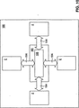
図10は図9に示されたシステムと同じように配置されたカスタム化可能なロバストな計算システム188のブロック図を示す。この図10に示されたカスタム化可能なロバストな計算システムだけが、単一の外部物体180に作動的に接続された複数の処理制御ユニット2を含む。この実施例では、4つの処理制御ユニット2が利用されており、各ユニットは外部物体180へ大きい、または追加された、もしくはスケーリングされたスマート技術を導入するための追加(および/または必要な場合にスケーリングされた)計算処理パワーを提供している。当業者であれば、必要に応じて外部物体180に実行させるのに任意の数の処理制御ユニットを使用できること、または単一システムとして複数の外部物体に複数の処理制御ユニットを作動的に結合できることが認識できよう。更に当業者であれば、1つのシステム内に複数の処理制御ユニットを実現でき、互いに独立したタスクを作動させたり、独立した、または関連するタスクを実行させることができることも認識できよう。
FIG. 10 shows a block diagram of a customizable and
図11を参照する。ここには別の一般的な説明のためのカスタム化可能なロバストな計算システムが示されており、ここでは外部物体の構造体内に処理制御ユニット2が物理的に含まれるか、または物理的にその一部となっているか、または外部物体に物理的に取り付けられるか、外部物体をサポートできるか、または他の方法で外部物体に物理的に結合されており、よって処理制御ユニット2は計算機能の他に追加機能を提供するようになっている。このように、作動的に接続するための手段は更に1つ以上のタイプの物理接続手段、または処理制御ユニット2を外部物体180に物理的に接続するための手段、例えば上記外部物体に係合するための手段、もしくはその他の任意の公知のデバイス、システムまたは方法を含む。例えば処理制御ユニットはその形状および材料の組成に起因し、外部物体の一部品として単に作動できるし、または外部物体内の負荷支持部材(すなわち外部物体自身の構造の一部)として作動できるし、または外部物体のための負荷支持部材として(すなわち処理制御ユニットに結合または取り付けられた構造体、もしくはデバイスをサポートするよう)作動できる。これら構造のいずれにおいても、上記のものと同様なカスタム化可能なロバストな計算システム188が得られ、外部物体180に処理制御ユニット2だけが物理的に結合される。図11は、外部物体180に物理的に結合された複数の処理制御ユニット2を示しているが、このカスタム化可能なロバストな計算システムが単一の処理制御ユニット2しか含まないようにすることを想到することもできる。
Please refer to FIG. Here is shown a customizable and robust computing system for another general description, where the
外部物体180に処理制御ユニット2が物理的に結合されている、図11に示されたカスタム化可能な計算システムでは、作動的に接続するための好ましい手段は、上記原理に基づき、処理制御ユニット2のダイナミックな背面に位置するユニバーサルポートを介した、処理制御ユニット2と外部物体180との間の直接接続部を含む。当然ながら、その他の接続方法およびシステムも可能であり、想到できる。
In the customizable computing system shown in FIG. 11 in which the
図12は外部物体180に処理制御ユニット2を結合するための一実施例を示す。図示された実施例では、処理制御ユニット2は外部物体180に電気的に、かつ物理的に作動可能に接続されている。物理的接続は外部物体180に形成された係合部材170を設け、これら部材を処理制御ユニット2に設けられたスライド受け部182内に嵌合または挿入することによって達成される(図4を参照したこれまでの説明を参照のこと)。スライド受け部182内に係合部材178を挿入することは、外部物体180へ処理制御ユニット2を物理的に接続するように効果的に機能するので、処理制御ユニットは外部物体自身の構造部品(すなわち負荷支持または非負荷支持部品)として働くことができるし、また1つ以上の外部物体の支持体として働くことができる。当然ながら、当業者が認識できるように、外部物体180に処理制御ユニットを物理的に接続するのに、他の方法およびシステムを使用することができ、これらの各々は本発明によってカバーし、保護すべきものである。
FIG. 12 shows an embodiment for coupling the
図12は外部物体180のまわりまたはその内部に存在する回路を処理制御ユニット2の回路に接続する接続コードを含むような、処理制御ユニット2を外部物体180に作動的に接続するための手段を更に示す。このような接続は処理制御ユニット2の1つ以上のポートを介して行うことが好ましい。
FIG. 12 shows means for operatively connecting the
処理制御ユニットはカスタム化可能なロバストな計算システムを提供するのに無数の方法で配置することができる。説明のために、以下、かかるいくつかのシステムについて説明するが、次の実施例は、カスタム化可能なロバストな計算システムを形成するのに1つ以上の処理制御ユニットを含むことができる、実質的に無限の想到可能な構造およびシステムだけでなく、かかるシステムを利用できる多数の異なるタイプのエンタプライズ用アプリケーションをも、当業者が認識するように、いかなる意味においても限定的なものと考えるべきではない。 Processing control units can be arranged in myriad ways to provide a robust computing system that can be customized. For purposes of explanation, several such systems are described below, but the following examples may include one or more processing control units to form a customizable and robust computing system. As those skilled in the art will recognize, not only the infinitely conceivable structures and systems, but also many different types of enterprise applications that can utilize such systems should be considered limiting in any sense. is not.
実施例1
本発明の処理制御ユニットは想到できる任意の環境に適合できるものと考えられるが、エンタプライズ用の基本的なアプリケーションの1つは家庭またはオフィス用の通常の計算システムまたはワークステーションとして働くコンピュータ、すなわち計算システムである。家庭またはオフィス用に設定した場合、処理制御ユニットは必要な、より広いスペースを自由にしたり、カモフラージュしたり、または視界から隠すことができる能力を提供できる。ユニットのサイズおよび重量によって、ユニットは極めてポータブルで、かつ容易に動き回ることができるだけでなく、従来の関連するコンピュータ用収納体では得られなかったスペース上の利点を提供できるようになっている。
Example 1
While the process control unit of the present invention is considered adaptable to any conceivable environment, one of the basic applications for enterprises is a computer that acts as a normal computing system or workstation for home or office, i.e. It is a calculation system. When configured for home or office, the processing control unit can provide the ability to free up, camouflage, or hide from view the required larger space. The size and weight of the unit makes it extremely portable and easy to move around, as well as providing space advantages not available with conventional related computer enclosures.
更にスケーリングされた処理を達成するために、別の処理制御ユニットにプロセス結合できる処理制御ユニットの能力に起因し、従来のコンピュータシステム、例えば通信業界用に構築されたシステムを省略できる。例えば現在実施されているような通信タワーのビル内にいくつかのサーバーを収納する代わりに、本発明の複数の処理制御ユニットを1つにプロセス結合し、直接タワーに搭載できる。この場合、処理制御ユニットは従来のサーバーの処理パワーよりも大きくないが、従来のサーバーと同じ量の処理パワーを提供できる。 Due to the ability of the processing control unit to be process-coupled to another processing control unit to achieve further scaled processing, conventional computer systems, such as systems built for the communications industry, can be omitted. For example, instead of housing several servers in a telecommunications tower building as currently practiced, the process control units of the present invention can be process combined into one and mounted directly on the tower. In this case, the processing control unit is not larger than the processing power of the conventional server, but can provide the same amount of processing power as the conventional server.
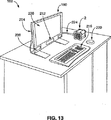
図13を参照すると、ここにはワークステーション環境内で利用すべきコンピュータの形態をしたカスタム化可能なロバストな計算システム188が示されている。このような特定の配置では、処理制御ユニット2は計算ソースを提供し、かつワークステーション内の周辺部品を制御するための従来の関係するコンピュータとして機能する。処理制御ユニット2は非周辺機器に基づく収納体を含むことが好ましい。図示された実施例では、カスタム化可能なロバストな計算システム188は接続手段184を介してモニタ200に作動的に接続された処理制御ユニット2を備える。コンピュータワークステーションにはハードディスクドライブ204、スピーカー208、CD−ROMドライブ212、キーボード216、マウス220および電源接続部224も含む。作動可能に接続するための手段は、処理制御ユニット2とモニタ200との間の有線接続部と、いくつかの周辺デバイスの間の無線技術とを含む。処理制御ユニット2はタスクを実行するよう、データを操作するための処理パワーを提供するので、処理制御ユニット2は駆動力となっている。
Referring to FIG. 13, there is shown a customizable and
図13はデスクに載せられたスタンドアローン部分としての処理制御ユニット2を示すが、処理制御ユニット2のロバストな性質によって、この制御ユニット2は目立たない場所、例えば壁内に設置したり、デスクの下に取り付けたり、または装飾装置または物体内に取り付けできる。従って、図示された実施例は、蹴飛ばしたり、またはタワー内部の冷却システムからの音を発生し易い従来のタワーを省略できる。
FIG. 13 shows the
実施例2
図14を参照すると、ここにはワークステーション環境内で利用すべきコンピュータの形態をした、カスタム化可能なロバストな別の計算システムが示されている。しかしながら、処理制御ユニット2が1つ以上の外部物体180、例えばモニタ230、延長アーム234およびベースまたはスタンド238のための物理的サポートして機能しているという点で、この実施例は図13に示された実施例と異なっている。更に、処理制御ユニット2は電気的かつ物理的に外部物体180に対して作動可能に接続されている。特に処理制御ユニット2はコンピュータの処理部品となっており、かつモニタおよびその他の周辺計算デバイス(例えばマウスおよびキーボードなど)に電気的に接続されている他に、負荷支持部材として機能している。この実施例では、処理制御ニット2はモニタ230をサスペンドされた状態にサポートする負荷支持部材である。更に処理制御ニット2は高い一に示されているスタンド238の延長アーム234に結合されているので、モニタ230とスタンド238を共に架橋するだけでなく、ロバストな計算システム全体の構造上の支持および安定性にも寄与している。この実施例では処理制御ユニット2はその収納体、すなわちメインサポートシャーシに直接取り付けられた負荷を支持できるように示されている。また、作動可能に接続するための手段184は特定の物理的接続(図示せず)の他に、電気的有線接続を含む。
Example 2
Referring to FIG. 14, there is shown another customizable and robust computing system in the form of a computer to be utilized within a workstation environment. However, this embodiment is illustrated in FIG. 13 in that the
実施例3
図15Aおよび15Bは、図13に衣召されたシステム、すなわち実施例に類似するカスタム化可能なロバストな計算システムを示しており、図15Aおよび15Bに示されたシステムまたは実施例だけがスナップオン周辺デバイスを有するデスクトップ計算システムのための制御センターとして作動または機能する処理制御ユニット2を示している。図示するように、周辺デバイスは処理制御ユニット2への外部接続部を介し、処理制御ユニット2によって処理制御ユニットいできる。これら図に示された実施例では、本発明は、処理制御ユニット2のダイナミックな背面を介し、処理制御ユニット2および特定の相互接続部または周辺トランスポートにプラグインされ、電気的に結合されるユニバーサル周辺パネル250に実質的にスナップオンされるスナップオン周辺デバイスを使用することを可能にするものである。この実施例では、ユニバーサル周辺パネル250は、基本的には処理制御ユニット2によって物理的かつ電気的に支持されたモニタまたはLCDスクリーンの背部である。接続手段258を使ってユニバーサル周辺パネル250内に第1周辺デバイス254(例えばCD−ROMドライブ)をスナップ嵌合できる。接続手段258には電気コネクタが設けられており、この電気コネクタは第1周辺デバイス254が処理制御ユニット2とインターフェースし、かつ電気的に接続できるようにしている。更に第1周辺デバイス254には識別されたコネクタが設けられており、このコネクタは周辺デバイスを接続手段258に接続し、かつこの手段と共に機能できるようにし、接続手段を機能させ、第1周辺デバイス254が使用するのに必要なバック平面上の適当な相互接続部に接続し、機能することができるようにしている。更に、第1周辺デバイス254はユニバーサル周辺パネル250内に見られるコネクタに類似したコネクタを丈夫に含むことができ、よって図示するように第2周辺デバイス262を第1周辺デバイス254に取り付け、かつ電気的に接続し、更に処理制御ユニット2に取り付け、電気的に接続できるようにしている。このタイプの周辺機器および接続技術、並びにシステムを使用することにより、使用および取り外しをより容易にするように、種々の周辺機器を積み重ねることができる。更にかなりの相互交換可能性が得られ、種々の周辺デバイスを所望に応じて取り付けたり取り外したりすることができる。
Example 3
FIGS. 15A and 15B show the system dressed in FIG. 13, ie a customizable and robust computing system similar to the embodiment, and only the system or embodiment shown in FIGS. 15A and 15B is snap-on. 1 shows a
実施例4
図16は外部物体180がラップトップコンピュータ270の形態をしたカスタム化可能なロバストな計算システム188を示す。周辺機器278にはI/O周辺機器274を有する処理制御ユニット2が選択的に結合されており、代表的なシステムはハイエンドなラップトップコンピュータとして機能できるようにしている。図16に示されるように、処理制御ユニット2は大型のI/O周辺機器274にカートリッジ状に選択的に挿入できるようになっている。周辺機器274はエンドユーザーのアプリケーションに応じてキーボード、モニタ、スピーカーおよびオプションのロジックを含む。ユニット2を一端周辺機器278から結合を外すか、取り出すと、ユニット2はユーザーが常に自分のファイルを有することができるようにするファイルを維持できる。従って、ユニット2はファイルのすべてを含むので、ユニット2と周辺機器278とを同期化させる必要はない。図16に示される実施例は1つのモジュラー式処理ユニットを含むが、本発明の他の実施例は多数の処理ユニットを利用できる。同様に、モジュラー式処理湯にと2を他の種々のタイプの周辺機器に挿入または他の方法で結合することができ、周辺機器は車両、家庭、オフィスなどにおけるエンタプライズを含む。音楽、映画、絵画または他の任意のオーディオおよび/またはビデオを保持し、提供するのに、ユニット2を使用できる。
Example 4
FIG. 16 shows a customizable and
実施例5
図17はカスタム化可能なロバストな計算システム188を示し、このいすてむでは外部物体180はフリップトップ周辺機器280の形態をしており、この周辺機器はモニタ、親指キーボードおよびマウス装置を含む。
Example 5
FIG. 17 illustrates a robust
実施例6
図18はカスタム化可能なロバストな計算システム188を示し、このシステムでは外部物体180はハンドヘルド周辺機器284の形態をしている。
Example 6
FIG. 18 shows a customizable and
実施例7
図19はカスタム化可能なロバストな計算システム188を示し、このシステムでは外部物体180は電子デバイス、例えばDVDプレイヤーの形態をしている。本発明の少なくとも一部の実施例によれば、周辺機器に基づかない収納体を有する処理制御ユニット2を中央処理ユニットまたはその他の電子デバイスで使用でき、この電子デバイスはテレビ、ステレオシステム、レコードユニット、セットトップボックス、DVD/CDプレイヤーまたはその他の任意の電子デバイスを含む。
Example 7
FIG. 19 shows a customizable and
実施例8
図20はカスタム化可能なロバストな計算システム188を示し、このシステムでは外部物体180は照明具300の形態をしている。特に図15は、処理制御ユニット2をどのように照明具300に組み込み、この照明具300のオンオフ、(スライドオンディマー312による)ディミングおよびその他の属性の制御、例えば電球が使用するワット数のモニタおよび必要なメンテナンスの管理センターまたはその他の所望する機能を制御できる。処理制御ユニット2はスライドオン照明モジュール308に作動可能に接続された状態に示されており、照明モジュール308は上記のように処理制御ユニット2のメインサポートシャーシに設けられたスライド受け部(図示せず)に挿入されるようになっている。照明モジュラー308は図示するように1つ以上の電球およびカバーをサポートしており、次に処理制御ユニット2はスライドオン取り付けブラケット304を介して天井構造体に取り付けられており、ブラケットはスライド受け部を使用して処理制御ユニット2にも結合されている。次に取り付けブラケット304は照明具300を吊り下げるための天井または壁に結合している。
Example 8
FIG. 20 shows a customizable and
実施例9
図21はカスタム化可能なロバストな計算システム188を示し、このシステムでは、外部物体180は住居用電圧モニタブレーカーボックス320の形態をしている。特に処理制御ユニット2は標準ブレーカーボックスを住居用電圧モニタブレーカーボックス320に変換するものとして示されている。このような例のセットアップでは、デュアル住居用処理制御ユニット2はブレーカーボックス320をプロセス制御し、ブレーカーボックス320内、および家屋全体に存在する電圧をリアルタイムでモニタするように機能する。各処理制御ユニット2には電圧モニタバックプレート324が取り付けられており、このバックプレートはスライド受け部82(図示せず)を使って取り付けられている。更にブレーカーボックス320がこのブレーカーボックス320の作動および制御に関連するその他のスマート機能を実行するように処理制御ユニット2に命令できる。この例に示したカスタム化可能なロバストな計算システムは単一の外部物体を制御するために2つの処理制御ユニットを含むことに留意すべきである。当業者であれば、その他の類似の構造も可能で割ることが想到できよう。
Example 9
FIG. 21 shows a customizable and
実施例10
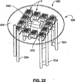
図22はカスタム化可能なロバストな計算システム188を示し、このシステムでは、外部物体180はテーブルまたはテーブルアセンブリ330の形態をしている。この実施例では、多数の処理制御ユニット2を利用し、これらユニットはテーブル330の負荷支持部品、すなわちレッグ334および頂部338に接続するだけでなく、スマート技術をテーブル330に導入し、よってテーブルが1つ以上のスマート機能を実行できるようにする部品を構成する。テーブルアセンブリ330はスライドオンレッグマウント334を使用しており、マウント334はテーブルアセンブリ330のレッグを構成するための1つ以上の接続手段を使って処理制御ユニット2に結合している。更に処理制御ユニット2は負荷支持コネクタ342を使って一体となるように(すなわち物理的および/または電気的に)作動可能に接続されている。テーブルアセンブリ330が種々の付加的スマート機能を実行できるようにするスライドオンDVDおよびハードドライブモジュール346も示されている。
Example 10
FIG. 22 shows a customizable and
実施例11
図23はカスタム化可能なロバストな計算システム188を示し、このシステムでは、外部物体180は特に802.11x分配のために使用される電気ソケット、すなわちプラグの形態をしている。処理制御ユニット2はACインターフェース350、ACプラグ周辺機器354および取り付けブラケット358に結合されている。ACプラグ周辺機器354および取り付けブラケット358はスライドオン周辺機器となっている。処理制御ユニット2には、このユニットへのac配電により給電され、処理制御ユニットは配電をモニタし、制御し、オーバーシーし、および/または割り当てをするためのスマートプラグとして使用されている。
Example 11
FIG. 23 shows a customizable and
一実施例では、処理制御ユニット2はルーターとして使用される。別の実施例では、このユニットはセキュリティシステムとして使用される。この別の実施例では処理制御ユニット2は配電をモニタし、必要に応じて安全を保証するために電力を遮断する。例えば処理制御ユニット2はある個人が配電に接触したことを検出でき、自動的に電力を遮断する。一部の実施例ではX10に基づく技術またはその他技術を使用して銅製ワイヤーラインを通して多数のエンタプライズを接続する。更に別の実施例では、多数のエンタプライズが例えばTCP/IPまたはその他のプロトコルを通してデータを交換する。
In one embodiment, the
上記のように、上記カスタム化可能なロバストな計算システムおよび図示されているエンタプライズ用アプリケーションは、使用できる外部物体およびアプリケーションの一部の単なる例である。当業者であれば、いずれも本発明の詳細な説明および特許請求の範囲内に入る、その他の多くの構成、環境、アプリケーションおよびセットアップについて認識できよう。従って、本発明の実施例はカスタム化可能なロバストな計算システム内でスマート製品を形成するために種々の 平凡な製品に関連して処理制御ユニットを利用することを含む。すべて網羅的に説明するわけではないが、処理制御ユニットと製品、システムおよびデバイスのその他の例を使ってスマート製品、システムおよび/またはデバイスを提供できる。これら一部の例として、加熱/冷却システム、給水システム、配電システム、家具、器具、機器、ギア、ドリル、工具、ビル、人工知能、車両、センサ、ビデオおよび/またはオーディオシステム、セキュリティシステムおよび多数の製品、システムおよび/またはデバイスを挙げることができる。 As noted above, the customizable robust computing system and the illustrated enterprise application are merely examples of some of the external objects and applications that can be used. Those skilled in the art will recognize many other configurations, environments, applications, and setups that all fall within the detailed description of the invention and the claims. Accordingly, embodiments of the present invention include utilizing a processing control unit in conjunction with various common products to form smart products within a customizable and robust computing system. Although not exhaustively described, other examples of process control units and products, systems and devices can be used to provide smart products, systems and / or devices. Some examples of these are heating / cooling systems, water supply systems, power distribution systems, furniture, appliances, equipment, gears, drills, tools, buildings, artificial intelligence, vehicles, sensors, video and / or audio systems, security systems and many more Products, systems and / or devices.
例えば処理制御ユニットを作動的に炉に接続し、炉システムの効率を制御することができる。効率が低下した場合、フィルタを交換し、システムのサービスをし、故障を識別することなどを、例えばEメールでビルのオーナーに伝えるように、処理制御ユニットにプログラムを組み込むことができる。同様に、処理制御ユニットを水道に関連して使用し、水の純度をモニタし、かつ汚染が生じた場合のけ異国をするようにできる。同様に、家電(例えば洗濯機、乾燥機、ディッシュウォッシャー、冷凍機など)を処理制御ユニットに関連して使用する場合に、これら家電をスマートにすることができる。更に、一酸化炭素、炭素菌またはその他の菌、放射性物質またはその他の物質もしくは有害な物質の検出を含む、セキュリティを提供するシステムに関連して処理制御ユニットを使用できる。更に、処理制御ユニットの安定性および汎用性に起因し、これらをこれまで使用できなかった場所に設置できる。少なくとも一部の実施例では、スーパー構造体と共に処理制御ユニットを使用することによって、処理制御ユニットはスーパー構造体の品質を活用できるようになる。 For example, a process control unit can be operatively connected to the furnace to control the efficiency of the furnace system. If the efficiency decreases, a program can be incorporated into the processing control unit to communicate to the building owner, for example, by e-mail, that the filter is replaced, the system is serviced, and the failure is identified. Similarly, a process control unit can be used in connection with water supply to monitor the purity of the water and to leave the country only if contamination occurs. Similarly, when home appliances (eg, washing machines, dryers, dishwashers, refrigerators, etc.) are used in connection with the process control unit, these home appliances can be made smart. Furthermore, the process control unit can be used in connection with systems that provide security, including detection of carbon monoxide, carbon bacteria or other fungi, radioactive material or other or harmful substances. Furthermore, due to the stability and versatility of the processing control unit, these can be installed in places where they could not be used. In at least some embodiments, using a process control unit with a superstructure allows the process control unit to take advantage of the quality of the superstructure.
例えば別の例として、種々の家電を使用して、802.11xネットワークまたはスマートホーム技術の権利を家屋構造体に設置するために使用すべき家屋またはその他の構造物またはビルの内外に処理制御ユニットを取り付け、これら家電をスマート装置に変換できる。 For example, as another example, a processing control unit in or out of a house or other structure or building that should be used to install 802.11x network or smart home technology rights in the house structure using various home appliances. You can convert these home appliances into smart devices.
処理制御ユニット2は有線ネットワークシステムまたは無線ネットワーク規格、例えば802.11a、802.11bおよびブルートゥースのための許容可能な全方向および/または指向性アンテナとしても使用できる。このような使用は、処理制御ユニット2が送信信号を受信し、細くできる種々の場所に設置できるようになっている好ましい金属形状および能力によって可能となる。
The
処理制御ユニット2、および特に第1インサート部材66、第2インサート部材70および第3インサート部材74は別の機能を実行するようにもできる。例えばライトスライドは他のスライド部品に電力およびデータを供給するワイヤーハーネスとして作動できるように利用できる。
The
これら説明は本発明の実施例に係わる1つ以上のモジュラー式処理ユニットの能力の単なる例にすぎない。以上で、本明細書において、本発明の説明のための実施例について説明したが、本発明はこれまで切見えシた種々の好ましい実施例だけに限定されるものではなく、むしろ当業者が本命妻子補の開示に基づき、理解できるような変形例、除外、組み合わせ(例えば種々の実施例にわたる特徴の組み合わせ)、適用および/または変更例を有する任意の、かつすべての実施例をふくむものであ。特許請求の範囲における限定は特許請求の範囲に使用した言語に基づき、広義に解釈すべきであり、本明細書内および本願の手続き中に記載した例だけに限定されるものではなく、これら例は非排他的なものであると見なすべきである。例えば本明細書における「好ましくは」なる用語は、非排他的であり、「好ましいが、これらだけに限定されるものではない」ことを意味するものである。ミーンズプラスファンクション(手段+機能)またはステッププラスファンクション(ステップ+機能)限定は特定のクレームの限定に対し、a)「のための手段」が明確に記載されていること、およびb)対応する機能が明確に記載されている限定において、次の条件のすべてが存在する場合にしか使用されない。 These descriptions are merely examples of the capabilities of one or more modular processing units according to embodiments of the present invention. As mentioned above, although the Example for description of this invention was demonstrated in this specification, this invention is not limited only to the various preferable Example which has been clearly seen until now, Rather, those skilled in the art will do it. Based on Disclosure of Tsumago's disclosure, including any and all examples having variations, exclusions, combinations (eg, combinations of features across various examples), applications and / or modifications that can be understood. . The limitations in the claims should be construed broadly based on the language used in the claims, and are not limited to the examples described herein and in the procedures of this application. Should be considered non-exclusive. For example, the term “preferably” as used herein is non-exclusive and means “preferably, but not limited to.” Means plus function (means + function) or step plus function (step + function) limitation is specific to the claim limitation, a) "means for" is clearly stated, and b) the corresponding function In the limitation where is clearly stated, it is used only when all of the following conditions exist:
発明の要旨、すなわち本質的な特徴事項から逸脱することなく、本発明を他の特定の形態で実施できる。本明細書に説明した実施例はすべての点において単に説明のためのものにすぎず、発明を限定すべきものではないと見なすべきである。従って、本発明の範囲はこれまでの説明ではなく、特許請求の範囲によって定められている。特許請求の範囲の均等の意義および範囲内に入るすべての変更は発明の範囲内に含まれるべきものである。 The present invention may be embodied in other specific forms without departing from the spirit or essential characteristics thereof. The embodiments described herein are merely illustrative in all respects and should not be construed as limiting the invention. Accordingly, the scope of the invention is defined by the appended claims rather than the foregoing description. All changes that come within the meaning and range of equivalency of the claims are to be embraced within their scope.
2 処理制御ユニット
10 収納モジュール
14 メインサポートシャーシ
34 ダイナミックな背面
38 第1エンドプレート
42 第2エンドプレート
46 第1エンドキャップ
50 第2エンドキャップ
54 一体モジュール
62 基板受け部
66 第1インサート
70 第2インサート
74 第3インサート
82 スライド受け部
2
Claims (18)
外部物体と、
前記処理制御ユニットを前記外部物体に作動可能に接続し、前記外部物体にインテリジェンスを導入し前記外部物体にスマート機能を実行させるための手段とを備えた、カスタム化可能なロバストな計算システム。 A processing control unit;
An external object,
A customizable and robust computing system comprising: a means for operatively connecting the processing control unit to the external object, means for introducing intelligence into the external object and causing the external object to perform smart functions.
複数の壁サポートおよび内部のコンピュータ部品を支持するための手段を含む複数の接合センターを有するメインサポートシャーシ、
インターフェースを必要とすることなく、周辺部品およびその他の計算部品を直接システムバスに接続するための支持体となるダイナミックな背面、および
前記メインサポートシャーシを収納し、前記収納モジュールの内側部分にアクセスするための手段を備えた収納モジュールと、
前記収納モジュールの前記接合センター内に配置された1つ以上のコンピュータ処理部品と、
前記収納モジュールの前記内側部分を冷却するための手段とを備えた、請求項1記載のカスタム化可能なロバストなコンピュータ処理システム。 The control unit is
A main support chassis having a plurality of joint centers including means for supporting a plurality of wall supports and internal computer components;
Without the need for an interface, it houses a dynamic back that serves as a support for connecting peripheral components and other computational components directly to the system bus, and houses the main support chassis to access the inner part of the storage module A storage module with means for
One or more computer processing components disposed within the joint center of the storage module;
The customizable and robust computer processing system of claim 1, comprising means for cooling the inner portion of the storage module.
前記外部物体または前記外部物体の部品を物理的にサポートする処理制御ユニットと、
前記処理制御ユニットを前記外部物体に作動可能に接続し、前記外部物体にインテリジェンスを導入し前記外部物体にスマート機能を実行させるための手段とを備えた、カスタム化可能なロバストな計算システム。 An external object,
A processing control unit that physically supports the external object or parts of the external object;
A customizable and robust computing system comprising: a means for operatively connecting the processing control unit to the external object, means for introducing intelligence into the external object and causing the external object to perform smart functions.
処理制御ユニットを前記外部物体に作動可能に接続するステップと、
前記処理制御ユニット内において1つ以上の計算機能を開始し、前記外部物体にスマート機能を実行させるステップとを備えた、外部物体にインテリジェンスを導入し、その内部でスマート機能を可能にするための方法。 Including an external object;
Operatively connecting a processing control unit to the external object;
Introducing intelligence into an external object and enabling a smart function therein comprising initiating one or more computing functions within the processing control unit and causing the external object to perform a smart function Method.
複数の壁サポートおよび内部のコンピュータ部品を支持するための手段を含む複数の接合センターを有するメインサポートシャーシ、
インターフェースを必要とすることなく、周辺部品およびその他の計算部品を直接システムバスに接続するための支持体となるダイナミックな背面、および
前記メインサポートシャーシを収納し、前記収納モジュールの内側部分にアクセスするための手段を備えた、非周辺機器に基づく収納モジュールと、
前記収納モジュールの前記接合センター内に配置された1つ以上のコンピュータ処理部品と、
前記収納モジュールの前記内側部分を冷却するための手段とを備えた、請求項16記載の方法。 The control unit is
A main support chassis having a plurality of joint centers including means for supporting a plurality of wall supports and internal computer components;
Without the need for an interface, it houses a dynamic back that serves as a support for connecting peripheral components and other computational components directly to the system bus, and houses the main support chassis to access the inner part of the storage module A storage module based on a non-peripheral device, with means for
One or more computer processing components disposed within the joint center of the storage module;
17. A method according to claim 16, comprising means for cooling the inner portion of the storage module.
第1、第2および第3側壁サポートを有するメインサポートシャーシと、
前記メインサポートシャーシに取り外し自在に結合され、複数の換気ポートを備えた第1および第2エンドプレートと、
前記メインサポートシャーシに取り外し自在に結合されたダイナミックな背面と、
前記収納モジュール内に取り外し自在に固定された3基板電気プリント回路基板構造とを備えた、請求項17記載の、非周辺機器用コンピュータ処理システム。 The storage body is substantially in the shape of a cube, so that the storage module is
A main support chassis having first, second and third sidewall supports;
First and second end plates removably coupled to the main support chassis and having a plurality of ventilation ports;
A dynamic back surface removably coupled to the main support chassis;
The computer processing system for a non-peripheral device according to claim 17, comprising a three-board electrical printed circuit board structure removably fixed in the storage module.
Applications Claiming Priority (4)
| Application Number | Priority Date | Filing Date | Title |
|---|---|---|---|
| US42012702P | 2002-10-22 | 2002-10-22 | |
| US45578903P | 2003-03-19 | 2003-03-19 | |
| US10/692,005 US7242574B2 (en) | 2002-10-22 | 2003-10-22 | Robust customizable computer processing system |
| PCT/US2003/033547 WO2004038555A2 (en) | 2002-10-22 | 2003-10-22 | Robust customizable computer processing system |
Related Child Applications (1)
| Application Number | Title | Priority Date | Filing Date |
|---|---|---|---|
| JP2010030181A Division JP5189117B2 (en) | 2002-10-22 | 2010-02-15 | A customizable and robust computer processing system |
Publications (1)
| Publication Number | Publication Date |
|---|---|
| JP2006504209A true JP2006504209A (en) | 2006-02-02 |
Family
ID=32180499
Family Applications (4)
| Application Number | Title | Priority Date | Filing Date |
|---|---|---|---|
| JP2005501660A Pending JP2006504209A (en) | 2002-10-22 | 2003-10-22 | A customizable and robust computer processing system |
| JP2010030181A Expired - Fee Related JP5189117B2 (en) | 2002-10-22 | 2010-02-15 | A customizable and robust computer processing system |
| JP2012242168A Pending JP2013020658A (en) | 2002-10-22 | 2012-11-01 | Robust customizable computer processing system |
| JP2014109408A Pending JP2014149879A (en) | 2002-10-22 | 2014-05-27 | Robust customizable computer processing system |
Family Applications After (3)
| Application Number | Title | Priority Date | Filing Date |
|---|---|---|---|
| JP2010030181A Expired - Fee Related JP5189117B2 (en) | 2002-10-22 | 2010-02-15 | A customizable and robust computer processing system |
| JP2012242168A Pending JP2013020658A (en) | 2002-10-22 | 2012-11-01 | Robust customizable computer processing system |
| JP2014109408A Pending JP2014149879A (en) | 2002-10-22 | 2014-05-27 | Robust customizable computer processing system |
Country Status (7)
| Country | Link |
|---|---|
| US (6) | US7242574B2 (en) |
| EP (1) | EP1557074A4 (en) |
| JP (4) | JP2006504209A (en) |
| AU (1) | AU2003284329A1 (en) |
| BR (1) | BR0315624A (en) |
| CA (1) | CA2504222C (en) |
| WO (1) | WO2004038555A2 (en) |
Cited By (3)
| Publication number | Priority date | Publication date | Assignee | Title |
|---|---|---|---|---|
| JP2008028339A (en) * | 2006-07-25 | 2008-02-07 | Matsushita Electric Works Ltd | Electric device case |
| JP2008071243A (en) * | 2006-09-15 | 2008-03-27 | Ict Solutions:Kk | Simplified computer fixable to back face of display device |
| KR20160007578A (en) * | 2013-06-07 | 2016-01-20 | 애플 인크. | Computer thermal system |
Families Citing this family (60)
| Publication number | Priority date | Publication date | Assignee | Title |
|---|---|---|---|---|
| KR101197513B1 (en) | 2002-10-22 | 2012-11-09 | 제이슨 에이. 설리반 | Systems and methods for providing a dynamically modular processing unit |
| US20120173732A1 (en) * | 2002-10-22 | 2012-07-05 | Sullivan Jason A | Systems and methods for providing resources and interactivity in computer systems |
| CA2504222C (en) | 2002-10-22 | 2012-05-22 | Jason A. Sullivan | Robust customizable computer processing system |
| US7256991B2 (en) * | 2002-10-22 | 2007-08-14 | Sullivan Jason A | Non-peripherals processing control module having improved heat dissipating properties |
| US7256996B2 (en) * | 2004-10-14 | 2007-08-14 | Bountiful Wifi Llc | Wireless router |
| JP2007102746A (en) * | 2005-09-06 | 2007-04-19 | Ict Solutions:Kk | Personal computer mounted with simplified computer on backface of liquid crystal display, and method for assembling personal computer with liquid crystal display |
| JP2007293913A (en) * | 2005-09-06 | 2007-11-08 | Ict Solutions:Kk | Personal computer with simple computer mounted on back of liquid-crystal display and method for assembling personal computer with liquid-crystal display |
| US7943865B2 (en) * | 2005-12-04 | 2011-05-17 | Ihab Ayoub | Device for isolation of electrical components |
| US20070156952A1 (en) * | 2005-12-29 | 2007-07-05 | Monigan Heather D | Digital storage safe |
| US7990724B2 (en) | 2006-12-19 | 2011-08-02 | Juhasz Paul R | Mobile motherboard |
| US20080158805A1 (en) * | 2006-12-27 | 2008-07-03 | Mazen Waheeb El Bteddini | Small portable multipurpose pc unit insertable into a multitude of operating stations |
| US20090127988A1 (en) * | 2007-11-20 | 2009-05-21 | Sergejs Lucuks | Device for a computer case cover |
| US8006407B2 (en) * | 2007-12-12 | 2011-08-30 | Richard Anderson | Drying system and method of using same |
| CA2656431C (en) | 2008-02-27 | 2015-04-14 | L&P Property Management Company | Computer docking station for a vehicle |
| US20090310293A1 (en) * | 2008-06-12 | 2009-12-17 | Datavan International Corp. | Quick-detachable mounting system |
| US8118997B2 (en) * | 2008-10-23 | 2012-02-21 | Whirlpool Corporation | Smart filter for an appliance |
| US8892238B2 (en) * | 2009-10-06 | 2014-11-18 | Edward T. Sweet | Edge break details and processing |
| US20110081839A1 (en) * | 2009-10-06 | 2011-04-07 | Apple Inc. | Method and apparatus for polishing a curved edge |
| US8111505B2 (en) | 2009-10-16 | 2012-02-07 | Apple Inc. | Computer housing |
| US20110089792A1 (en) * | 2009-10-16 | 2011-04-21 | Apple Inc. | Portable computer housing |
| CN201654638U (en) * | 2009-11-26 | 2010-11-24 | 鸿富锦精密工业(深圳)有限公司 | Computer system |
| TWI488562B (en) * | 2010-08-30 | 2015-06-11 | Liquidcool Solutions Inc | Extruded server case |
| JP5810806B2 (en) * | 2011-09-30 | 2015-11-11 | 富士通株式会社 | Electronic device and manufacturing method thereof |
| US9756927B2 (en) * | 2011-11-30 | 2017-09-12 | Apple Inc. | Mounting system for portable electronic device |
| US20130242491A1 (en) * | 2012-03-15 | 2013-09-19 | Steven H. Goldstein | Modular computer systems |
| US9513667B2 (en) | 2012-05-29 | 2016-12-06 | Google Technology Holdings LLC | Methods, apparatuses, and systems for radio frequency management between devices |
| USD684571S1 (en) | 2012-09-07 | 2013-06-18 | Apple Inc. | Electronic device |
| US20130319640A1 (en) * | 2012-06-04 | 2013-12-05 | Motorola Mobility Llc | Methods, apparatuses, and systems for thermal management between devices |
| TWM441311U (en) * | 2012-06-08 | 2012-11-11 | Leng-Hong Zhang | Casing formed with heat sink combination |
| CN103596297B (en) * | 2012-08-13 | 2017-04-12 | 华为技术有限公司 | Radio remote unit devices and assemblies thereof |
| US9563239B2 (en) | 2012-09-10 | 2017-02-07 | Apple Inc. | Internal computer assembly features and methods |
| US9720558B2 (en) * | 2012-11-30 | 2017-08-01 | Verizon and Redbox Digital Entertainment Services, LLC | Systems and methods for providing a personalized media service user interface |
| US8964406B2 (en) * | 2012-12-11 | 2015-02-24 | ESPi LLC | Battery backup cover system |
| US9612632B2 (en) * | 2013-04-30 | 2017-04-04 | Apple Inc. | Wireless electronic device with component cooling structures |
| CN108594951B (en) * | 2013-06-07 | 2020-01-21 | 苹果公司 | Internal architecture for computer |
| WO2014197735A1 (en) * | 2013-06-07 | 2014-12-11 | Apple Inc. | Computer system |
| US11899509B2 (en) | 2013-06-07 | 2024-02-13 | Apple Inc. | Computer housing |
| US9207729B2 (en) | 2013-06-07 | 2015-12-08 | Apple Inc. | Computer Architecture |
| RO130806A1 (en) * | 2014-05-02 | 2015-12-30 | Serghei Ignat | Display-attachable minicomputer |
| US9785187B2 (en) * | 2014-08-07 | 2017-10-10 | Microsoft Technology Licensing, Llc | Modular computing device |
| US9430001B2 (en) | 2015-01-05 | 2016-08-30 | Microsoft Technology Licensing, Llc | Modular computing device |
| WO2016111790A1 (en) * | 2015-01-05 | 2016-07-14 | Intel Corporation | Unified chassis construction for all in one computer |
| US20160236770A1 (en) * | 2015-02-16 | 2016-08-18 | Hamilton Sundstrand Corporation | Electronic Control with Interchangeable Subsystem Modules |
| US9830297B2 (en) * | 2015-02-26 | 2017-11-28 | Spire Global, Inc. | Processor system for control of modular autonomous system |
| TWM520229U (en) * | 2015-07-16 | 2016-04-11 | 鋐寶科技股份有限公司 | Electronic apparatus |
| US9575517B1 (en) * | 2016-01-15 | 2017-02-21 | Ncr Corporation | Reversible input/output (I/O) |
| US10296003B2 (en) | 2016-05-12 | 2019-05-21 | Georgia Tech Research Corporation | Autonomous vehicle research system |
| US10345920B2 (en) * | 2016-05-18 | 2019-07-09 | Kevin R. Stoops | Keyboard/keyboard enclosure |
| US10936087B2 (en) * | 2016-05-18 | 2021-03-02 | Kevin R. Stoops | Keyboard assembly |
| US10104795B2 (en) * | 2016-11-18 | 2018-10-16 | Illinois Tool Works Inc. | Protective assemblies for enclosures |
| TWI650057B (en) * | 2016-12-09 | 2019-02-01 | 群暉科技股份有限公司 | Electronic device |
| USD948991S1 (en) | 2017-05-18 | 2022-04-19 | Kevin R. Stoops | Bracket |
| US10185371B1 (en) * | 2017-07-20 | 2019-01-22 | Lenovo (Singapore) Pte. Ltd. | Orientable computing device |
| KR102030824B1 (en) * | 2017-11-01 | 2019-10-10 | 현대오트론 주식회사 | Electronic control device |
| US10945347B2 (en) * | 2018-12-27 | 2021-03-09 | lonQ, Inc. | Techniques for making hermetic feedthroughs for enclosures |
| JP7041085B2 (en) * | 2019-02-05 | 2022-03-23 | ファナック株式会社 | Electronic device |
| CN111526675A (en) * | 2020-03-23 | 2020-08-11 | 何宏成 | Automobile engine and control method thereof |
| CN111556683B (en) * | 2020-06-02 | 2021-04-09 | 巩国一 | Water supply and drainage monitoring device for building engineering |
| CN214412924U (en) * | 2020-11-20 | 2021-10-15 | 京东方科技集团股份有限公司 | Network adapter and terminal equipment |
| DE202021104596U1 (en) * | 2021-08-26 | 2022-11-29 | Weidmüller Interface GmbH & Co. KG | housing system |
Family Cites Families (581)
| Publication number | Priority date | Publication date | Assignee | Title |
|---|---|---|---|---|
| US744897A (en) | 1902-02-19 | 1903-11-24 | Ferdinand Braun | Means for directing electric waves for use in wireless telegraphy. |
| US876644A (en) * | 1907-06-04 | 1908-01-14 | John J Hennessey | Car-frame construction. |
| US2270314A (en) | 1940-01-31 | 1942-01-20 | John D Kraus | Corner reflector antenna |
| US2270315A (en) | 1940-02-16 | 1942-01-20 | Carl F Krueger | Window |
| GB1394431A (en) * | 1971-06-24 | 1975-05-14 | Plessey Co Ltd | Multiprocessor data processing system |
| US3932016A (en) | 1973-04-02 | 1976-01-13 | Stromberg-Carlson Corporation | Printed circuit card receptacle |
| US3921177A (en) | 1973-04-17 | 1975-11-18 | Ball Brothers Res Corp | Microstrip antenna structures and arrays |
| US3896419A (en) | 1974-01-17 | 1975-07-22 | Honeywell Inf Systems | Cache memory store in a processor of a data processing system |
| US4232356A (en) * | 1979-02-07 | 1980-11-04 | Burroughs Corporation | Logic card frame |
| JPS55151398U (en) | 1979-04-17 | 1980-10-31 | ||
| JPS55151398A (en) * | 1979-05-15 | 1980-11-25 | Matsushita Electric Works Ltd | Device for mounting on printed board |
| FR2496996A1 (en) | 1980-12-18 | 1982-06-25 | Thomson Csf | HYPERFREQUENCY TRANSMISSION LINE OF THE AIR TRIPLAQUE TYPE AND USES THEREOF |
| US4389080A (en) | 1981-07-15 | 1983-06-21 | General Electric | Plug-in ceramic hybrid module |
| JPS595705A (en) | 1982-07-01 | 1984-01-12 | Fujitsu Ltd | Microwave antenna circuit |
| US4511964A (en) | 1982-11-12 | 1985-04-16 | Hewlett-Packard Company | Dynamic physical memory mapping and management of independent programming environments |
| US4479198A (en) | 1983-02-23 | 1984-10-23 | Honeywell Information Systems Inc. | Modular computer system |
| JPS60207398A (en) | 1984-03-30 | 1985-10-18 | 松下電器産業株式会社 | Device for containing printed board |
| US4656559A (en) * | 1984-05-10 | 1987-04-07 | Ultima Electronics Ltd. | Holder and heat sink for electronic components |
| JPS6127268A (en) | 1984-07-18 | 1986-02-06 | Ricoh Co Ltd | Recording apparatus |
| JPS6164197A (en) | 1984-09-06 | 1986-04-02 | 富士通株式会社 | Printed board mounting block structure |
| JPS6164197U (en) | 1984-10-03 | 1986-05-01 | ||
| US4816993A (en) * | 1984-12-24 | 1989-03-28 | Hitachi, Ltd. | Parallel processing computer including interconnected operation units |
| IT1184015B (en) * | 1985-12-13 | 1987-10-22 | Elsag | MULTI-PROCESSOR SYSTEM WITH MULTIPLE HIERARCHICAL LEVELS |
| US4791531A (en) | 1987-03-09 | 1988-12-13 | Tech-S, Inc. | Extruded enclosure for electrical apparatus |
| US4837735A (en) | 1987-06-09 | 1989-06-06 | Martin Marietta Energy Systems, Inc. | Parallel machine architecture for production rule systems |
| US4843403A (en) | 1987-07-29 | 1989-06-27 | Ball Corporation | Broadband notch antenna |
| US4814777A (en) | 1987-07-31 | 1989-03-21 | Raytheon Company | Dual-polarization, omni-directional antenna system |
| US4829372A (en) | 1987-08-20 | 1989-05-09 | Telaction Corporation | Presentation player |
| US5136718A (en) * | 1987-09-04 | 1992-08-04 | Digital Equipment Corporation | Communications arrangement for digital data processing system employing heterogeneous multiple processing nodes |
| US4876644A (en) * | 1987-10-30 | 1989-10-24 | International Business Machines Corp. | Parallel pipelined processor |
| US4853704A (en) | 1988-05-23 | 1989-08-01 | Ball Corporation | Notch antenna with microstrip feed |
| JPH03263903A (en) | 1989-04-28 | 1991-11-25 | Misao Haishi | Miniature antenna |
| WO1990015394A1 (en) * | 1989-06-02 | 1990-12-13 | Aisi Research Corporation | Appliance interface for exchanging data |
| US5805474A (en) * | 1989-06-08 | 1998-09-08 | Norand Corporation | Portable work station type-data collection system having an improved handgrip and an optical reader to be directed thereby |
| GB8913311D0 (en) | 1989-06-09 | 1990-04-25 | Marconi Co Ltd | Antenna arrangement |
| JPH0348044U (en) | 1989-09-20 | 1991-05-08 | ||
| FR2659500B1 (en) | 1990-03-09 | 1992-05-15 | Alcatel Espace | METHOD OF FORMING THE DIAGRAM OF A HIGH EFFICIENCY ACTIVE ANTENNA FOR ELECTRONICALLY SCANNED RADAR AND ANTENNA USING THE SAME. |
| US5142255A (en) | 1990-05-07 | 1992-08-25 | The Texas A&M University System | Planar active endfire radiating elements and coplanar waveguide filters with wide electronic tuning bandwidth |
| US5251097A (en) | 1990-06-11 | 1993-10-05 | Supercomputer Systems Limited Partnership | Packaging architecture for a highly parallel multiprocessor system |
| JPH0455169A (en) | 1990-06-18 | 1992-02-21 | Mazda Motor Corp | Standard position detecting method of rear wheel steering device for vehicle |
| US5094624A (en) | 1990-12-18 | 1992-03-10 | Molex Incorporated | Metal latch for SIMM socket |
| US5051868A (en) | 1990-07-25 | 1991-09-24 | Sun Microsystems, Inc. | Computer construction |
| JP3018437B2 (en) | 1990-08-29 | 2000-03-13 | 横河電機株式会社 | Electromagnetic coupling computer module device and computer device using the same |
| US5214712A (en) | 1990-09-11 | 1993-05-25 | Matsushita Electric Industrial Co., Ltd. | Pattern inspection system for inspecting defect of land pattern for through-hole on printed board |
| US5377356A (en) * | 1990-09-19 | 1994-12-27 | Aeg Transportation Systems, Inc. | Propulsion control system central processing unit board |
| ATE180586T1 (en) * | 1990-11-13 | 1999-06-15 | Ibm | PARALLEL ASSOCIATIVE PROCESSOR SYSTEM |
| JPH04206284A (en) | 1990-11-29 | 1992-07-28 | Matsushita Electric Ind Co Ltd | Connection device between printed board inside shield case and cable outside |
| US5131140A (en) | 1991-02-26 | 1992-07-21 | Hewlett-Packard Company | Method for evaluating plane splits in printed circuit boards |
| US5076794A (en) | 1991-04-29 | 1991-12-31 | Compaq Computer Corporation | Space-saving mounting interconnection between electrical components and a printed circuit board |
| RU2066067C1 (en) | 1991-06-27 | 1996-08-27 | Институт точной механики и вычислительной техники им.С.А.Лебедева РАН | Central processor for multiple-processor computer system |
| FR2680026B1 (en) * | 1991-07-30 | 1996-12-20 | Commissariat Energie Atomique | SYSTEM ARCHITECTURE IN PROCESSOR BOARD WITH PARALLEL STRUCTURE. |
| US5181855A (en) | 1991-10-03 | 1993-01-26 | Itt Corporation | Simplified contact connector system |
| JPH05145208A (en) | 1991-11-18 | 1993-06-11 | Toshiba Corp | Circuit unit |
| JPH05206678A (en) | 1992-01-28 | 1993-08-13 | Nec Corp | Multilayer interconnection board |
| WO1993018559A1 (en) | 1992-03-06 | 1993-09-16 | Augat Inc. | Edge card interconnection system |
| JP3094631B2 (en) | 1992-03-19 | 2000-10-03 | 富士通株式会社 | Heat dissipation device for enclosure |
| US5227957A (en) * | 1992-05-14 | 1993-07-13 | Deters John B | Modular computer system with passive backplane |
| EP0648404B1 (en) | 1992-06-29 | 1998-11-25 | Elonex Technologies, Inc. | Modular notebook computer |
| US5689654A (en) | 1992-06-29 | 1997-11-18 | Elonex F.P. Holdings, Ltd. | Digital assistant system including a host computer with a docking bay for the digital assistant wherein a heat sink is moved into contact with a docked digital assistant for cooling the digital assistant |
| US5539616A (en) | 1992-06-29 | 1996-07-23 | Elonex Technologies, Inc. | Modular portable computer |
| JPH0637416A (en) | 1992-07-14 | 1994-02-10 | Fujitsu Ltd | Printed wiring board |
| NL9201413A (en) | 1992-08-05 | 1994-03-01 | Lely Nv C Van Der | Device for milking animals. |
| US5311397A (en) * | 1992-08-06 | 1994-05-10 | Logistics Management Inc. | Computer with modules readily replaceable by unskilled personnel |
| US5337464A (en) | 1992-11-20 | 1994-08-16 | Dell U.S.A., L.P. | Method of convertibly upgrading a personal computer |
| US5383192A (en) | 1992-12-23 | 1995-01-17 | Intel Corporation | Minimizing the likelihood of slip between the instant a candidate for a break event is generated and the instant a microprocessor is instructed to perform a break, without missing breakpoints |
| US5430607A (en) | 1992-12-31 | 1995-07-04 | North Atlantic Industries, Inc. | Rugged modular portable computer including modules hinged along an edge |
| JPH0795667B2 (en) | 1993-01-18 | 1995-10-11 | 日本電気株式会社 | Transversal filter |
| US5349132A (en) | 1993-02-08 | 1994-09-20 | Apple Computer, Inc. | Methods and apparatus for modular computer construction |
| US5761033A (en) * | 1993-02-19 | 1998-06-02 | Sejus Corporation | Open computer system with externally interconnected peripheral modules |
| US6523079B2 (en) | 1993-02-19 | 2003-02-18 | Elonex Ip Holdings Ltd | Micropersonal digital assistant |
| JPH06260361A (en) | 1993-03-03 | 1994-09-16 | Nippon Steel Corp | Production of inductor for thin power supply |
| WO1994022180A1 (en) | 1993-03-18 | 1994-09-29 | Gabriel Electronics Incorporated | Stacked biconical omnidirectional antenna |
| US5390081A (en) | 1993-03-22 | 1995-02-14 | Stratus Computer, Inc. | Fault-tolerant power distribution system for rack-mounted hardware |
| US6853293B2 (en) | 1993-05-28 | 2005-02-08 | Symbol Technologies, Inc. | Wearable communication system |
| JPH0713660A (en) | 1993-06-21 | 1995-01-17 | Toshiba Corp | Portable electronic equipment |
| US5671430A (en) * | 1993-06-30 | 1997-09-23 | Gunzinger; Anton | Parallel data processing system with communication apparatus control |
| US5589406A (en) * | 1993-07-30 | 1996-12-31 | Ag Technology Co., Ltd. | Method of making TFT display |
| US5640430A (en) | 1993-09-02 | 1997-06-17 | Motorola, Inc. | Method for detecting valid data in a data stream |
| JP3247023B2 (en) | 1994-01-13 | 2002-01-15 | ローム株式会社 | Dielectric capacitor, non-volatile memory and method of manufacturing the same |
| IT1267375B1 (en) | 1994-01-31 | 1997-02-05 | Olivetti & Co Spa | COMPUTER |
| US5646823A (en) | 1994-03-16 | 1997-07-08 | Amori; Michael D. | Computer and instrument enclosure |
| US5541611A (en) | 1994-03-16 | 1996-07-30 | Peng; Sheng Y. | VHF/UHF television antenna |
| EP0678796B1 (en) | 1994-04-13 | 1998-06-24 | Siemens Aktiengesellschaft | Compact programmable logic controller and central unit of a modular programmable logic controller |
| US5658962A (en) | 1994-05-20 | 1997-08-19 | Minnesota Mining And Manufacturing Company | Omega-hydrofluoroalkyl ethers, precursor carboxylic acids and derivatives thereof, and their preparation and application |
| DE4418231C2 (en) | 1994-05-25 | 1997-02-27 | Siemens Ag | Modularly structured service personal computer |
| KR950035209A (en) * | 1994-05-26 | 1995-12-30 | 가나이 쯔도무 | Horizontally distributed network system and multiprocessor system |
| US5786792A (en) | 1994-06-13 | 1998-07-28 | Northrop Grumman Corporation | Antenna array panel structure |
| US5600538A (en) | 1994-07-08 | 1997-02-04 | Apple Computer, Inc. | Personal computer and housing structure having circuit board removable horizontally and sub-chassis removable from the top thereof |
| JP3379075B2 (en) * | 1994-07-11 | 2003-02-17 | インターナショナル・ビジネス・マシーンズ・コーポレーション | Computer with modular removable card cage |
| US5786984A (en) | 1994-08-23 | 1998-07-28 | Packard Bell Nec | Modular portable personal computer |
| DE19540915A1 (en) | 1994-11-10 | 1996-05-15 | Raymond Engineering | Redundant arrangement of solid state memory modules |
| US5694294A (en) * | 1995-01-27 | 1997-12-02 | Hitachi, Ltd. | Portable computer with fan moving air from a first space created between a keyboard and a first circuit board and a second space created between the first circuit board and a second circuit board |
| JP3190797B2 (en) | 1995-02-09 | 2001-07-23 | 日本電気株式会社 | Small electronic equipment |
| US5661494A (en) | 1995-03-24 | 1997-08-26 | The United States Of America As Represented By The Administrator Of The National Aeronautics And Space Administration | High performance circularly polarized microstrip antenna |
| US5557506A (en) * | 1995-03-31 | 1996-09-17 | Alantec | Expandable data processing chassis and method of assembly thereof |
| US5774337A (en) | 1995-05-01 | 1998-06-30 | Apple Computer, Inc. | Appliance having EMI shielding |
| US5736796A (en) | 1995-05-01 | 1998-04-07 | Apple Computer, Inc. | Printed circuit board having split voltage planes |
| US5557291A (en) | 1995-05-25 | 1996-09-17 | Hughes Aircraft Company | Multiband, phased-array antenna with interleaved tapered-element and waveguide radiators |
| US5696893A (en) * | 1995-06-07 | 1997-12-09 | Xerox Corporation | System for generically describing and scheduling operation of modular printing machine |
| US5748912A (en) | 1995-06-13 | 1998-05-05 | Advanced Micro Devices, Inc. | User-removable central processing unit card for an electrical device |
| DE19536848A1 (en) | 1995-10-02 | 1997-04-03 | Bosch Gmbh Robert | Subrack for an electronic control unit with signal processing components and fast working digital components |
| JPH09114543A (en) | 1995-10-02 | 1997-05-02 | Xybernaut Corp | Handfree computer system |
| US5625531A (en) | 1995-10-25 | 1997-04-29 | General Electric Company | Motor control center pilot devices bracket |
| US5602721A (en) * | 1995-12-22 | 1997-02-11 | Tandem Computers | Expandable modular computer system |
| KR970049283A (en) * | 1995-12-28 | 1997-07-29 | 김광호 | Easy to expand computer |
| JP3234860B2 (en) | 1996-02-05 | 2001-12-04 | 株式会社日立製作所 | Computer system |
| US6347218B1 (en) * | 1996-02-28 | 2002-02-12 | Nokia Mobile Phones Limited | Electronic device with housing supplement |
| US6153881A (en) * | 1996-07-31 | 2000-11-28 | Fire Sentry Corporation | Fire detector and housing |
| US5801072A (en) | 1996-03-14 | 1998-09-01 | Lsi Logic Corporation | Method of packaging integrated circuits |
| US6370546B1 (en) * | 1996-04-08 | 2002-04-09 | Sony Corporation | First information processing device directly accessing, updating second information process device and vice versa via transmission bus management authority |
| US5701231A (en) | 1996-05-03 | 1997-12-23 | Citicorp Development Center, Inc. | Personal computer enclosure with peripheral device mounting system |
| US6018456A (en) | 1996-05-31 | 2000-01-25 | Cmd Technology, Inc. | Enclosure for removable computer peripheral equipment |
| US5754396A (en) | 1996-07-22 | 1998-05-19 | Compaq Computer Corporation | Modular desktop computer having enhanced serviceability |
| JPH1056673A (en) * | 1996-08-07 | 1998-02-24 | Hitachi Ltd | Radio communication equipment and information processor |
| US5999952A (en) * | 1997-08-15 | 1999-12-07 | Xybernaut Corporation | Core computer unit |
| US6029183A (en) | 1996-08-29 | 2000-02-22 | Xybernaut Corporation | Transferable core computer |
| US20030156383A1 (en) | 1996-08-29 | 2003-08-21 | Jenkins Michael D. | Core computer system |
| JP3035252U (en) | 1996-08-30 | 1997-03-11 | 産協株式会社 | Cover panel coupling structure and case using the same |
| SE511426C2 (en) | 1996-10-28 | 1999-09-27 | Ericsson Telefon Ab L M | Apparatus and method of shielding electronics |
| KR100193851B1 (en) | 1996-11-05 | 1999-06-15 | 윤종용 | Small antenna of portable radio |
| US5996831A (en) | 1996-11-07 | 1999-12-07 | Sphinx Elektronik Gmbh | Closure device |
| JPH10173349A (en) | 1996-12-10 | 1998-06-26 | Fujitsu Ten Ltd | Case for wiring board and electronic device |
| US5863211A (en) * | 1996-12-12 | 1999-01-26 | International Business Machines Corporation | Inter-book-package mechanical and electrical connection system |
| US5948087A (en) * | 1996-12-16 | 1999-09-07 | Nexar Technologies, Inc. | Computer architecture having platform-dependent and platform-independent boards forming the motherboard |
| JPH10232788A (en) | 1996-12-17 | 1998-09-02 | Fujitsu Ltd | Signal processor and software |
| US5896273A (en) | 1996-12-31 | 1999-04-20 | Compaq Computer Corp. | Modular computer chassis interchangeable between stand alone and rack mounted states |
| KR100286369B1 (en) | 1997-01-06 | 2001-04-16 | 윤종용 | Computer system |
| US5761034A (en) | 1997-01-06 | 1998-06-02 | Chu; Shi | Portable main frame for a computer having upper and lower covers provided with computer components and pivotally connected together |
| JP3048044B2 (en) | 1997-02-28 | 2000-06-05 | 東興建設株式会社 | Ground improvement method and its equipment |
| US6023507A (en) | 1997-03-17 | 2000-02-08 | Sun Microsystems, Inc. | Automatic remote computer monitoring system |
| JPH10270879A (en) | 1997-03-26 | 1998-10-09 | Toshiba Corp | Structure for cooling electronic apparatus |
| US5793616A (en) | 1997-03-31 | 1998-08-11 | Compaq Computer Corp. | Computer system with special circuit board arrangement |
| US5926143A (en) | 1997-04-23 | 1999-07-20 | Qualcomm Incorporated | Multi-frequency band rod antenna |
| US6021453A (en) * | 1997-04-24 | 2000-02-01 | Klingman; Edwin E. | Microprocessor unit for use in an indefinitely extensible chain of processors with self-propagation of code and data from the host end, self-determination of chain length and ID, (and with multiple orthogonal channels and coordination ports) |
| US5909357A (en) * | 1997-04-24 | 1999-06-01 | Orr; Tom | Vertically stacked computer modules shaped to indicate compatibility with vertical cooling shaft extending throughout |
| JPH10307637A (en) | 1997-05-07 | 1998-11-17 | Toshiba Corp | Portable electronic equipment |
| US6304459B1 (en) | 1997-05-22 | 2001-10-16 | Xybernaut Corp. | Mobile computer |
| GB2328026B (en) * | 1997-06-16 | 2002-01-30 | Ultra Electronics Ltd | Electrical polarisation distribution of a vessel |
| US6181549B1 (en) | 1997-06-24 | 2001-01-30 | Dell Products, L.P. | Chassis retaining system for an electronics rack |
| JP3035252B2 (en) | 1997-07-22 | 2000-04-24 | タキゲン製造株式会社 | Rotary drawer lock device |
| CA2244369A1 (en) | 1997-07-30 | 1999-01-30 | Nec Corporation | Multiplex radio communication apparatus |
| JPH1168344A (en) | 1997-08-08 | 1999-03-09 | Toyota Autom Loom Works Ltd | Case for electric device |
| US6043987A (en) | 1997-08-25 | 2000-03-28 | Compaq Computer Corporation | Printed circuit board having a well structure accommodating one or more capacitor components |
| US6005767A (en) | 1997-11-14 | 1999-12-21 | Vadem | Portable computer having articulated display |
| US6032257A (en) | 1997-08-29 | 2000-02-29 | Compaq Computer Corporation | Hardware theft-protection architecture |
| US6001330A (en) | 1997-09-12 | 1999-12-14 | Elmaleh; David R. | Diagnostic and therapeutic alkylenediamine compounds and process |
| US6704838B2 (en) | 1997-10-08 | 2004-03-09 | Seagate Technology Llc | Hybrid data storage and reconstruction system and method for a data storage device |
| JP3048044U (en) | 1997-10-15 | 1998-05-06 | 蔡 坤明 | Notebook computer |
| JP3828997B2 (en) | 1997-10-15 | 2006-10-04 | 日本碍子株式会社 | Gas separator |
| US6331938B1 (en) | 1997-10-28 | 2001-12-18 | Surecom Technology Corporation | Structural and electrical connections for stacked computer devices |
| US6188571B1 (en) | 1997-11-03 | 2001-02-13 | Aiwa Raid Technology, Inc. | High density RAID subsystem with highly integrated controller |
| US6542926B2 (en) | 1998-06-10 | 2003-04-01 | Compaq Information Technologies Group, L.P. | Software partitioned multi-processor system with flexible resource sharing levels |
| JPH11143583A (en) | 1997-11-05 | 1999-05-28 | Matsushita Electric Ind Co Ltd | Heat radiator for portable personal computer |
| US5992955A (en) | 1997-11-17 | 1999-11-30 | Hon Hai Prcision Ind. Co., Ltd. | Structure of computer |
| JPH11154563A (en) | 1997-11-21 | 1999-06-08 | Ntt Advanced Technology Corp | Cover having polarity key for connector |
| JPH11154038A (en) | 1997-11-21 | 1999-06-08 | Matsushita Electric Ind Co Ltd | Electronic equipment with cooling fan |
| KR100251499B1 (en) | 1997-11-25 | 2000-04-15 | 윤종용 | The method of hot-plugging |
| US6011330A (en) | 1997-12-18 | 2000-01-04 | Sarnoff Corporation | Miniature power supply |
| US6501429B2 (en) * | 1998-02-02 | 2002-12-31 | Seiko Epson Corporation | Portable information processing apparatus |
| US6137686A (en) | 1998-04-10 | 2000-10-24 | Casio Computer Co., Ltd. | Interchangeable modular arrangement of computer and accessory devices |
| US6216185B1 (en) | 1998-05-01 | 2001-04-10 | Acqis Technology, Inc. | Personal computer peripheral console with attached computer module |
| JP2908432B1 (en) * | 1998-06-03 | 1999-06-21 | 埼玉日本電気株式会社 | Built-in antenna of mobile phone |
| JP4107717B2 (en) | 1998-06-19 | 2008-06-25 | 株式会社ケー・エフ・シー | Pipe type lock bolt |
| WO2000000903A1 (en) * | 1998-06-30 | 2000-01-06 | Mitsubishi Denki Kabushiki Kaisha | Multiple cpu unit |
| GB2341057A (en) | 1998-08-28 | 2000-03-01 | Ibm | Allocating names to network resources for shared access |
| US6037846A (en) | 1998-10-09 | 2000-03-14 | Nortel Networks Corporation | Surface mount EMI gasket filter |
| US6467009B1 (en) * | 1998-10-14 | 2002-10-15 | Triscend Corporation | Configurable processor system unit |
| US6388206B2 (en) | 1998-10-29 | 2002-05-14 | Agilent Technologies, Inc. | Microcircuit shielded, controlled impedance “Gatling gun”via |
| US6321335B1 (en) | 1998-10-30 | 2001-11-20 | Acqis Technology, Inc. | Password protected modular computer method and device |
| FR2785476A1 (en) | 1998-11-04 | 2000-05-05 | Thomson Multimedia Sa | Multiple beam wireless reception system has circular multiple beam printed circuit with beam switching mechanism, mounted on camera |
| US6229710B1 (en) * | 1998-11-13 | 2001-05-08 | Chenbro Micom Co., Ltd. | Computer main board case |
| US6532152B1 (en) * | 1998-11-16 | 2003-03-11 | Intermec Ip Corp. | Ruggedized hand held computer |
| US6259605B1 (en) | 1998-12-22 | 2001-07-10 | Dell Usa, L.P. | Front accessible computer and chassis |
| US6351375B1 (en) * | 1999-01-26 | 2002-02-26 | Dell Usa, L.P. | Dual-purpose backplane design for multiple types of hard disks |
| US6292718B2 (en) | 1999-01-28 | 2001-09-18 | International Business Machines Corp. | Electronic control system |
| US6369849B1 (en) * | 1999-01-28 | 2002-04-09 | Vosi Technologies, Inc. | Remote inspection device |
| EP1026688A3 (en) | 1999-02-02 | 2001-06-13 | Siemens Information and Communication Networks Inc. | Removable integrated multiple internal disk drive subsystem |
| US6388870B1 (en) | 1999-02-04 | 2002-05-14 | Palm, Inc. | Housing for a handheld computer |
| US6288893B1 (en) | 1999-02-04 | 2001-09-11 | Compaq Computer Corporation | Desktop computer system having reduced footprint semi-mobile CPU unit |
| US6388877B1 (en) * | 1999-02-04 | 2002-05-14 | Palm, Inc. | Handheld computer with open accessory slot |
| US6865076B2 (en) * | 1999-02-04 | 2005-03-08 | Palmone, Inc. | Electronically-enabled housing apparatus for a computing device |
| US6058011A (en) * | 1999-02-12 | 2000-05-02 | Compaq Computer Corporation | Computer chassis with integrated cooling features |
| JP2000232287A (en) * | 1999-02-12 | 2000-08-22 | Mitsubishi Electric Corp | Spontaneous air-cooling electronic equipment enclosure |
| US6992627B1 (en) | 1999-02-27 | 2006-01-31 | Rangestar Wireless, Inc. | Single and multiband quarter wave resonator |
| US6191750B1 (en) | 1999-03-03 | 2001-02-20 | Composite Optics, Inc. | Traveling wave slot antenna and method of making same |
| US6282433B1 (en) | 1999-04-14 | 2001-08-28 | Ericsson Inc. | Personal communication terminal with a slot antenna |
| US6157533A (en) * | 1999-04-19 | 2000-12-05 | Xybernaut Corporation | Modular wearable computer |
| US6666705B1 (en) | 1999-04-30 | 2003-12-23 | Intel Corporation | Method and apparatus for AGP universal connector |
| US6351246B1 (en) | 1999-05-03 | 2002-02-26 | Xtremespectrum, Inc. | Planar ultra wide band antenna with integrated electronics |
| US6643777B1 (en) | 1999-05-14 | 2003-11-04 | Acquis Technology, Inc. | Data security method and device for computer modules |
| US6718415B1 (en) | 1999-05-14 | 2004-04-06 | Acqis Technology, Inc. | Computer system and method including console housing multiple computer modules having independent processing units, mass storage devices, and graphics controllers |
| AUPQ439299A0 (en) | 1999-12-01 | 1999-12-23 | Silverbrook Research Pty Ltd | Interface system |
| US20010048793A1 (en) * | 1999-05-27 | 2001-12-06 | Edwin Dair | Method and apparatus for multiboard fiber optic modules and fiber optic module arrays |
| US6795926B1 (en) | 1999-05-28 | 2004-09-21 | Dell Usa, L.P. | Prevention of power state change in response to chassis intrusion when computer system is not in powered up power state |
| US6220346B1 (en) | 1999-05-29 | 2001-04-24 | Halliburton Energy Services, Inc. | Thermal insulation vessel |
| US6446192B1 (en) * | 1999-06-04 | 2002-09-03 | Embrace Networks, Inc. | Remote monitoring and control of equipment over computer networks using a single web interfacing chip |
| US6633231B1 (en) * | 1999-06-07 | 2003-10-14 | Horiba, Ltd. | Communication device and auxiliary device for communication |
| US6389499B1 (en) | 1999-06-09 | 2002-05-14 | Western Digital Ventures, Inc. | Integrated computer module |
| JP2001068293A (en) | 1999-06-25 | 2001-03-16 | Toto Ltd | Dust adhesion preventing unit and image device with dust adhesion preventing unit |
| US6222735B1 (en) | 1999-07-29 | 2001-04-24 | Micron Electronics, Inc. | Minitower computer housing and minitower computer |
| US6618698B1 (en) | 1999-08-12 | 2003-09-09 | Quickturn Design Systems, Inc. | Clustered processors in an emulation engine |
| US6229700B1 (en) | 1999-08-16 | 2001-05-08 | Saint Song Corp. | Portable computer host without any user interface |
| US6261104B1 (en) | 1999-08-16 | 2001-07-17 | Micron Electronics, Inc. | Riser card assembly and method for its installation |
| US6490157B2 (en) * | 1999-09-01 | 2002-12-03 | Intel Corporation | Method and apparatus for providing managed modular sub-environments in a personal computer |
| CA2299591C (en) | 1999-09-03 | 2002-12-03 | Xybernaut Corporation | Core computer system |
| US6911947B1 (en) | 1999-09-08 | 2005-06-28 | Thomson Licensing S.A. | Method and apparatus for reducing multipath distortion in a television signal |
| US6151209A (en) | 1999-09-20 | 2000-11-21 | Mitac International Corporation | Modular computer assembly having system circuit module and peripheral circuit module |
| US6349038B1 (en) | 1999-09-21 | 2002-02-19 | Dell Usa, L.P. | EMC characteristics of a printed circuit board |
| US6157537A (en) * | 1999-09-23 | 2000-12-05 | Getac Corporation | Data processing apparatus having a liquid heat-dissipating system |
| US6489932B1 (en) | 1999-09-30 | 2002-12-03 | Prasanna R. Chitturi | Display device including an integral docking station for a palm sized computing device |
| US7340763B1 (en) * | 1999-10-26 | 2008-03-04 | Harris Scott C | Internet browsing from a television |
| CA2299572C (en) | 1999-11-18 | 2004-05-04 | Xybernaut Corporation | Personal communicator |
| DE60035798T2 (en) | 1999-12-01 | 2008-04-30 | Cool Options, Inc. | STRUCTURE OF A HEAT-RELATED MATERIAL |
| WO2001042937A1 (en) | 1999-12-06 | 2001-06-14 | Henry Milan | Modular stackable component system including universal serial bus hub |
| DE19958825A1 (en) | 1999-12-07 | 2001-06-13 | Zeiss Carl Jena Gmbh | Control system monitoring method for optical instrument, involves registering data regarding state of control units, in master capable microprocessor |
| US7155711B2 (en) | 1999-12-10 | 2006-12-26 | Sedna Patent Services, Llc | Method and apparatus providing remote reprogramming of programmable logic devices using embedded JTAG physical layer and protocol |
| US7223105B2 (en) | 1999-12-16 | 2007-05-29 | Paricon Technologies Corporation | Cable connector incorporating anisotropically conductive elastomer |
| US6373715B1 (en) | 1999-12-17 | 2002-04-16 | Intel Corporation | Orienting multiple processors on two sides of a printed circuit board |
| US6246573B1 (en) * | 2000-01-20 | 2001-06-12 | Cieos, Inc. | Operatory computer with portable display |
| JP2001291970A (en) * | 2000-02-02 | 2001-10-19 | Sharp Corp | Case for electric product, stage for electrical appliance, and video apparatus comprising them |
| US6603430B1 (en) | 2000-03-09 | 2003-08-05 | Tyco Electronics Logistics Ag | Handheld wireless communication devices with antenna having parasitic element |
| EP1282848A1 (en) | 2000-03-15 | 2003-02-12 | J-Line Co, Ltd. | Computer case |
| US6629181B1 (en) * | 2000-03-16 | 2003-09-30 | Tektronix, Inc. | Incremental bus structure for modular electronic equipment |
| US6307742B1 (en) | 2000-04-19 | 2001-10-23 | Hewlett-Packard Company | Computer with readily accessible motherboard |
| US6704819B1 (en) | 2000-04-19 | 2004-03-09 | Microsoft Corporation | Method and apparatus for device sharing and arbitration |
| US6396453B2 (en) | 2000-04-20 | 2002-05-28 | Ems Technologies Canada, Ltd. | High performance multimode horn |
| US6871344B2 (en) | 2000-04-24 | 2005-03-22 | Microsoft Corporation | Configurations for binding software assemblies to application programs |
| US7237138B2 (en) | 2000-05-05 | 2007-06-26 | Computer Associates Think, Inc. | Systems and methods for diagnosing faults in computer networks |
| JP2002032150A (en) * | 2000-05-09 | 2002-01-31 | Sony Corp | Information processor |
| JP2001320454A (en) * | 2000-05-11 | 2001-11-16 | Fuji Photo Film Co Ltd | Mobile phone with camera |
| JP2002064283A (en) * | 2000-05-17 | 2002-02-28 | Hitachi Metals Ltd | Casing for electronic unit |
| US6542354B1 (en) * | 2000-06-09 | 2003-04-01 | Nokia Mobile Phones, Ltd. | Device with interchangeable user-interfaces and method for doing same |
| US6727774B1 (en) | 2000-06-19 | 2004-04-27 | Sun Microsystems, Inc. | Bypass capacitor methods for achieving a desired value of electrical impedance between parallel planar conductors of an electrical power distribution structure, and associated electrical power distribution structures |
| JP2002015337A (en) | 2000-06-28 | 2002-01-18 | Victor Co Of Japan Ltd | Three-dimensional image drawing device |
| US6636918B1 (en) | 2000-06-29 | 2003-10-21 | International Business Machines Corporation | Mobile computing device and associated base stations |
| JP2002016684A (en) * | 2000-06-30 | 2002-01-18 | Sony Corp | Portable terminal device and radio card modem |
| WO2002007037A1 (en) | 2000-07-17 | 2002-01-24 | Galactic Computing Corporation | Method and system for providing dynamic hosted service management |
| DE20014578U1 (en) | 2000-08-23 | 2000-11-16 | Enlight Corp | Computer case with removable frame for a CD-ROM drive |
| US6781925B2 (en) * | 2000-09-01 | 2004-08-24 | Nokia Mobile Phones Ltd. | Portable communication device |
| JP5041499B2 (en) * | 2000-09-21 | 2012-10-03 | 庸美 徳原 | Combined computer |
| US6487080B2 (en) | 2000-09-22 | 2002-11-26 | Linux Networx, Inc. | Sub rack based vertical housing for computer systems |
| US6388880B1 (en) | 2000-10-19 | 2002-05-14 | Fijitsu Network Communications, Inc. | Removable fan tray assembly with latching features |
| US6954850B1 (en) | 2000-10-30 | 2005-10-11 | Matsushita Electric Works, Ltd. | Electronic device that uses a pager network for remote reprogramming of the device |
| US6512963B1 (en) * | 2000-11-16 | 2003-01-28 | International Business Machines Corporation | Library system having empty cartridge storage cell coded label stripe |
| FR2817661A1 (en) | 2000-12-05 | 2002-06-07 | Thomson Multimedia Sa | DEVICE FOR RECEIVING AND / OR TRANSMITTING MULTI-BEAM SIGNALS |
| US6525696B2 (en) | 2000-12-20 | 2003-02-25 | Radio Frequency Systems, Inc. | Dual band antenna using a single column of elliptical vivaldi notches |
| US20020086703A1 (en) * | 2000-12-28 | 2002-07-04 | Brother International Corporation | Mobile computing device docking station |
| DE10065118A1 (en) | 2000-12-28 | 2002-07-04 | Bosch Gmbh Robert | System and method for controlling and / or monitoring a control device network having at least two control devices |
| CN1653571B (en) * | 2000-12-29 | 2013-01-02 | 弗图有限公司 | Casing |
| JP2002215337A (en) | 2001-01-16 | 2002-08-02 | Nec Corp | Disc array system |
| US6718408B2 (en) | 2001-01-18 | 2004-04-06 | Hewlett-Packard Development Company, L.P. | Interchangeable and configurable input/output module for a computing deviceco |
| US20020097555A1 (en) | 2001-01-19 | 2002-07-25 | Smith Mitchell A. | Small form factor computer |
| US20020099513A1 (en) | 2001-01-25 | 2002-07-25 | Keezer David Clark | Systems and methods for testing multi-gigahertz digital systems and components |
| DE10106138B4 (en) | 2001-02-10 | 2006-02-23 | Agilent Technologies, Inc. (n.d.Ges.d.Staates Delaware), Palo Alto | Modular measuring and / or testing device |
| US6784855B2 (en) | 2001-02-15 | 2004-08-31 | Microsoft Corporation | Methods and systems for a portable, interactive display device for use with a computer |
| JP3671855B2 (en) * | 2001-03-02 | 2005-07-13 | 秀 島▲ざき▼ | Mobile phone |
| US6597567B2 (en) | 2001-03-05 | 2003-07-22 | Toshiba America Information Systems, Inc. | Corner support members for housing system |
| KR100407646B1 (en) | 2001-03-12 | 2003-12-01 | 이디텍 주식회사 | piggyback monitor |
| US6900383B2 (en) | 2001-03-19 | 2005-05-31 | Hewlett-Packard Development Company, L.P. | Board-level EMI shield that adheres to and conforms with printed circuit board component and board surfaces |
| US6567254B2 (en) | 2001-03-20 | 2003-05-20 | Northern Technologies, Inc. | Methods and systems for reducing clamp voltages in surge protection circuitry |
| US20020140147A1 (en) * | 2001-03-27 | 2002-10-03 | Sun Microsystems, Inc. | Computer hardware test stand |
| JP2002290087A (en) | 2001-03-28 | 2002-10-04 | Densei Lambda Kk | On-board mounting-type electronic equipment and on- board mounting-type power-supply unit |
| US6957291B2 (en) | 2001-03-29 | 2005-10-18 | Quantum Corporation | Removable disk storage array emulating tape library having backup and archive capability |
| JP2002298099A (en) | 2001-03-30 | 2002-10-11 | Toshiba Corp | Electronic equipment |
| JP3738195B2 (en) * | 2001-03-30 | 2006-01-25 | 三洋電機株式会社 | Mobile phone terminal |
| US20020145847A1 (en) | 2001-04-04 | 2002-10-10 | Crosby Catherine K. | Portable computer |
| US6895532B2 (en) | 2001-05-03 | 2005-05-17 | Hewlett-Packard Development Company, L.P. | Wireless server diagnostic system and method |
| US6512488B2 (en) | 2001-05-15 | 2003-01-28 | Time Domain Corporation | Apparatus for establishing signal coupling between a signal line and an antenna structure |
| FR2825206A1 (en) | 2001-05-23 | 2002-11-29 | Thomson Licensing Sa | DEVICE FOR RECEIVING AND / OR TRANSMITTING ELECTROMAGNETIC WAVES WITH OMNIDIRECTIONAL RADIATION |
| US6898705B2 (en) | 2001-05-31 | 2005-05-24 | International Business Machines Corporation | Automatic appliance server re-provision/re-purposing method |
| US6552691B2 (en) | 2001-05-31 | 2003-04-22 | Itt Manufacturing Enterprises | Broadband dual-polarized microstrip notch antenna |
| JP2003008736A (en) * | 2001-06-22 | 2003-01-10 | Pioneer Electronic Corp | Portable information terminal |
| US6654241B2 (en) | 2001-06-29 | 2003-11-25 | Intel Corporation | High availability small foot-print server |
| US6650302B2 (en) | 2001-07-13 | 2003-11-18 | Aether Wire & Location | Ultra-wideband monopole large-current radiator |
| US6798647B2 (en) * | 2001-07-16 | 2004-09-28 | Hewlett-Packard Development Company, L.P. | Portable computer with integrated PDA I/O docking cradle |
| US6636958B2 (en) | 2001-07-17 | 2003-10-21 | International Business Machines Corporation | Appliance server with a drive partitioning scheme that accommodates application growth in size |
| US6690576B2 (en) | 2001-07-31 | 2004-02-10 | Hewlett Packard Development Company, L.P. | Externally mounted on-line replaceable fan module |
| US6482042B1 (en) | 2001-08-29 | 2002-11-19 | Emc Corporation | Techniques for accessing a circuit board utilizing an improved adaptor |
| US7337333B2 (en) | 2001-09-19 | 2008-02-26 | Dell Products L.P. | System and method for strategic power supply sequencing in a computer system with multiple processing resources and multiple power supplies |
| US6574098B2 (en) * | 2001-09-19 | 2003-06-03 | Palm, Inc. | Handheld computer casing with grooved feature formed on a decorative surface |
| JP4120192B2 (en) | 2001-09-25 | 2008-07-16 | 松下電工株式会社 | Discharge lamp lighting device |
| US6680843B2 (en) | 2001-09-28 | 2004-01-20 | International Business Machines Corporation | All-in-one personal computer with tool-less quick-release features for various elements thereof including a reusable thin film transistor monitor |
| US6819550B2 (en) * | 2001-11-08 | 2004-11-16 | Apple Computer, Inc. | Computer controlled display device |
| US6567272B1 (en) | 2001-11-09 | 2003-05-20 | Dell Products L.P. | System and method for utilizing system configurations in a modular computer system |
| US7330919B2 (en) | 2001-11-09 | 2008-02-12 | Aten Technology, Inc. | Television with integrated asynchronous/synchronous KVMP signal switch for console and peripheral devices |
| US6904482B2 (en) | 2001-11-20 | 2005-06-07 | Intel Corporation | Common boot environment for a modular server system |
| DE10162853C1 (en) | 2001-12-17 | 2003-06-05 | Iav Gmbh | Motor vehicle control system has program code of at least one function of program resident in and executed by one controller placed in another controller coupled to bus system |
| US7052392B2 (en) | 2001-12-31 | 2006-05-30 | Igt | Method and apparatus for providing an advantage to a player in a bonus game |
| US6714411B2 (en) | 2001-12-31 | 2004-03-30 | Hewlett-Packard Development Company, L.P. | Computer server hot plug fan tray assembly and method of fan removal |
| US6639309B2 (en) | 2002-03-28 | 2003-10-28 | Sandisk Corporation | Memory package with a controller on one side of a printed circuit board and memory on another side of the circuit board |
| US7298228B2 (en) | 2002-05-15 | 2007-11-20 | Hrl Laboratories, Llc | Single-pole multi-throw switch having low parasitic reactance, and an antenna incorporating the same |
| KR100526585B1 (en) | 2002-05-27 | 2005-11-08 | 삼성탈레스 주식회사 | Planar antenna with circular and linear polarization. |
| US6703981B2 (en) | 2002-06-05 | 2004-03-09 | Motorola, Inc. | Antenna(s) and electrochromic surface(s) apparatus and method |
| US8238718B2 (en) | 2002-06-19 | 2012-08-07 | Microsoft Corporaton | System and method for automatically generating video cliplets from digital video |
| US6721651B1 (en) * | 2002-06-28 | 2004-04-13 | Garmin Ltd. | Rugged, waterproof, navigation device with touch panel |
| US6862173B1 (en) | 2002-07-11 | 2005-03-01 | Storage Technology Corporation | Modular multiple disk drive apparatus |
| US7006073B2 (en) * | 2002-07-29 | 2006-02-28 | Mobicom Corporation | Electronic device incorporating a generic user interface |
| EP1394661A1 (en) * | 2002-08-28 | 2004-03-03 | Agilent Technologies, Inc. - a Delaware corporation - | Instrument enclosure apparatus |
| US7228963B1 (en) | 2002-08-30 | 2007-06-12 | Display Technologies, Inc. | Anti-theft display box |
| JP4201550B2 (en) | 2002-08-30 | 2008-12-24 | 富士通株式会社 | Load balancer |
| US7127255B2 (en) | 2002-10-01 | 2006-10-24 | Trango Systems, Inc. | Wireless point to multipoint system |
| US6988226B2 (en) | 2002-10-17 | 2006-01-17 | Wind River Systems, Inc. | Health monitoring system for a partitioned architecture |
| US7103745B2 (en) | 2002-10-17 | 2006-09-05 | Wind River Systems, Inc. | Two-level operating system architecture |
| US7256991B2 (en) | 2002-10-22 | 2007-08-14 | Sullivan Jason A | Non-peripherals processing control module having improved heat dissipating properties |
| CA2504222C (en) | 2002-10-22 | 2012-05-22 | Jason A. Sullivan | Robust customizable computer processing system |
| US20140250267A1 (en) | 2002-10-22 | 2014-09-04 | Jason A. Sullivan | Systems and methods for providing dynamic hybrid storage |
| KR101197513B1 (en) | 2002-10-22 | 2012-11-09 | 제이슨 에이. 설리반 | Systems and methods for providing a dynamically modular processing unit |
| US20130271905A1 (en) | 2002-10-22 | 2013-10-17 | Jason A. Sullivan | Systems and methods for providing dynamic computing systems |
| US20120151098A1 (en) | 2002-10-22 | 2012-06-14 | Sullivan Jason A | Systems and methods for providing a universal computing system |
| US20120173732A1 (en) | 2002-10-22 | 2012-07-05 | Sullivan Jason A | Systems and methods for providing resources and interactivity in computer systems |
| US6996500B2 (en) | 2002-10-30 | 2006-02-07 | Hewlett-Packard Development Company, L.P. | Method for communicating diagnostic data |
| US7209089B2 (en) | 2004-01-22 | 2007-04-24 | Hans Gregory Schantz | Broadband electric-magnetic antenna apparatus and method |
| KR100542572B1 (en) | 2003-02-10 | 2006-01-11 | 삼성전자주식회사 | Apparatus and method displaying used file area and the memory area divided according to file attribute |
| US6806845B2 (en) | 2003-01-14 | 2004-10-19 | Honeywell Federal Manufacturing & Technologies, Llc | Time-delayed directional beam phased array antenna |
| US6765539B1 (en) | 2003-01-24 | 2004-07-20 | Input Output Precise Corporation | Planar multiple band omni radiation pattern antenna |
| JP4279699B2 (en) | 2003-01-31 | 2009-06-17 | パナソニック株式会社 | Semiconductor memory card, control program. |
| US7263248B2 (en) | 2003-02-11 | 2007-08-28 | Avago Technologies Fiber Ip (Singapore) Pte. Ltd. | Optical via to pass signals through a printed circuit board |
| US7277295B2 (en) | 2003-02-28 | 2007-10-02 | Cisco Technology, Inc. | Industrial ethernet switch |
| US20040174675A1 (en) | 2003-03-06 | 2004-09-09 | Ming-Tson Liu | Book-style computer attachable to LCD monitor |
| KR20030036364A (en) | 2003-03-14 | 2003-05-09 | 주식회사 넷플랫 | Structure for modular computer |
| JP2004282329A (en) | 2003-03-14 | 2004-10-07 | Senyu Communication:Kk | Dual band omnidirectional antenna for wireless lan |
| EP1460771B1 (en) | 2003-03-19 | 2006-05-31 | Sony Ericsson Mobile Communications AB | A switchable antenna arrangement |
| US20040193824A1 (en) | 2003-03-24 | 2004-09-30 | Johnson Steven C. | Expandable capacity storage device |
| US6881098B2 (en) | 2003-04-14 | 2005-04-19 | Hewlett-Packard Development Company, L.P. | System and method for selectively communicatively coupling and transmitting power between an electronic device and a peripheral component |
| US20040214543A1 (en) | 2003-04-28 | 2004-10-28 | Yasuo Osone | Variable capacitor system, microswitch and transmitter-receiver |
| US7263632B2 (en) | 2003-05-07 | 2007-08-28 | Microsoft Corporation | Programmatic computer problem diagnosis and resolution and automated reporting and updating of the same |
| US6975510B1 (en) | 2003-05-09 | 2005-12-13 | Linux Networx | Ventilated housing for electronic components |
| US7334028B2 (en) | 2003-05-21 | 2008-02-19 | Hewlett-Packard Development Company, L.P. | Tiered multi-source software support using automated diagnostic-data transfers |
| US9069666B2 (en) | 2003-05-21 | 2015-06-30 | Hewlett-Packard Development Company, L.P. | Systems and methods for controlling error reporting and resolution |
| US7467417B2 (en) | 2003-06-18 | 2008-12-16 | Architecture Technology Corporation | Active verification of boot firmware |
| US20050007692A1 (en) | 2003-06-26 | 2005-01-13 | Spectra Logic Corporation | Magazine-Based Data Cartridge Library |
| FR2857165A1 (en) | 2003-07-02 | 2005-01-07 | Thomson Licensing Sa | BI-BAND ANTENNA WITH DOUBLE ACCESS |
| US7180457B2 (en) | 2003-07-11 | 2007-02-20 | Raytheon Company | Wideband phased array radiator |
| US6970367B2 (en) | 2003-08-20 | 2005-11-29 | Matsushita Electric Industrial Co., Ltd. | Switching power supply |
| CN1282092C (en) | 2003-08-25 | 2006-10-25 | 联想(北京)有限公司 | Safety chip information processing apparatus and starting method based on chip |
| US7619683B2 (en) | 2003-08-29 | 2009-11-17 | Aptina Imaging Corporation | Apparatus including a dual camera module and method of using the same |
| GB2427966B (en) | 2003-09-22 | 2007-05-16 | Thales Holdings Uk Plc | An antenna |
| US7064729B2 (en) | 2003-10-01 | 2006-06-20 | Arc Wireless Solutions, Inc. | Omni-dualband antenna and system |
| US7159053B1 (en) | 2003-10-10 | 2007-01-02 | Douglas Lakin | Portable flat display adaptor |
| US7280082B2 (en) | 2003-10-10 | 2007-10-09 | Cisco Technology, Inc. | Antenna array with vane-supported elements |
| US20050086413A1 (en) | 2003-10-15 | 2005-04-21 | Super Talent Electronics Inc. | Capacity Expansion of Flash Memory Device with a Daisy-Chainable Structure and an Integrated Hub |
| US6977624B1 (en) | 2003-10-17 | 2005-12-20 | Szente Pedro A | Antenna directivity enhancer |
| US20050102451A1 (en) | 2003-11-06 | 2005-05-12 | Chicony Electronics Co. Ltd | Programmable wireless receiver |
| US6914570B2 (en) | 2003-11-10 | 2005-07-05 | Motorola, Inc. | Antenna system for a communication device |
| US7092246B2 (en) | 2003-11-18 | 2006-08-15 | Kabushiki Kaisha Toshiba | Apparatus for connecting a display to a body case of an electronic device |
| CN1898837A (en) | 2003-11-21 | 2007-01-17 | 阿蒂密有限公司 | Ultrawide antenna |
| KR100621092B1 (en) | 2003-11-27 | 2006-09-08 | 삼성전자주식회사 | Method and apparatus for sharing application using P2P |
| US7068510B2 (en) | 2003-12-04 | 2006-06-27 | International Business Machines Corporation | Dissipating heat reliably in computer systems |
| JP2005190297A (en) | 2003-12-26 | 2005-07-14 | Toshiba Corp | Server, information processor and casing |
| US7508663B2 (en) | 2003-12-29 | 2009-03-24 | Rackable Systems, Inc. | Computer rack cooling system with variable airflow impedance |
| WO2005064747A1 (en) | 2003-12-30 | 2005-07-14 | Telefonaktiebolaget Lm Ericsson (Publ) | Antenna device, and array antenna, with planar notch element feed |
| EP1555595A3 (en) | 2004-01-13 | 2011-11-23 | LG Electronics, Inc. | Apparatus for controlling power of processor having a plurality of cores and control method of the same |
| US6993618B2 (en) | 2004-01-15 | 2006-01-31 | Super Talent Electronics, Inc. | Dual-mode flash storage exchanger that transfers flash-card data to a removable USB flash key-drive with or without a PC host |
| US7092248B2 (en) | 2004-01-28 | 2006-08-15 | Paul Shu | Detachable modular computer |
| US7584382B2 (en) | 2004-02-19 | 2009-09-01 | Microsoft Corporation | Method and system for troubleshooting a misconfiguration of a computer system based on configurations of other computer systems |
| US7119982B2 (en) | 2004-03-05 | 2006-10-10 | Spectra Logic Corporation | Data cartridge library operable with a multipiece magazine, drive bay, user interface, an entry/exit port, and universal electronics bay |
| US7286436B2 (en) | 2004-03-05 | 2007-10-23 | Netlist, Inc. | High-density memory module utilizing low-density memory components |
| US7826205B2 (en) | 2004-03-08 | 2010-11-02 | Originatic Llc | Electronic device having a movable input assembly with multiple input sides |
| US20050205292A1 (en) | 2004-03-18 | 2005-09-22 | Etenna Corporation. | Circuit and method for broadband switching noise suppression in multilayer printed circuit boards using localized lattice structures |
| US8131830B2 (en) | 2004-04-19 | 2012-03-06 | Hewlett-Packard Development Company, L.P. | System and method for providing support services using administrative rights on a client computer |
| US20050237716A1 (en) | 2004-04-21 | 2005-10-27 | International Business Machines Corporation | Air flow system and method for facilitating cooling of stacked electronics components |
| US7372695B2 (en) | 2004-05-07 | 2008-05-13 | Rackable Systems, Inc. | Directional fan assembly |
| US7408772B2 (en) | 2004-05-14 | 2008-08-05 | Hewlett-Packard Development Company, L.P. | Fan tray electronics enclosure |
| US7193565B2 (en) | 2004-06-05 | 2007-03-20 | Skycross, Inc. | Meanderline coupled quadband antenna for wireless handsets |
| US7230437B2 (en) | 2004-06-15 | 2007-06-12 | Formfactor, Inc. | Mechanically reconfigurable vertical tester interface for IC probing |
| TWI256252B (en) | 2004-06-18 | 2006-06-01 | Coretronic Corp | Modularized rotatable signal control box |
| TWI259354B (en) | 2004-06-25 | 2006-08-01 | Via Tech Inc | System and method of real-time power management |
| US7176837B2 (en) | 2004-07-28 | 2007-02-13 | Asahi Glass Company, Limited | Antenna device |
| US7184264B2 (en) | 2004-09-23 | 2007-02-27 | Imation Corp. | Connectable memory devices to provide expandable memory |
| US20060069896A1 (en) | 2004-09-27 | 2006-03-30 | Sigmatel, Inc. | System and method for storing data |
| US20060065431A1 (en) | 2004-09-29 | 2006-03-30 | Trucco Horacio A | Self-reflowing printed circuit board and application methods |
| US7377603B2 (en) | 2004-10-14 | 2008-05-27 | Hewlett-Packard Development Company, L.P. | Computing device mounting systems |
| JP4055169B2 (en) | 2004-10-27 | 2008-03-05 | 財団法人大日本蚕糸会 | Thickness low tension reeling device |
| US7158089B2 (en) | 2004-11-29 | 2007-01-02 | Qualcomm Incorporated | Compact antennas for ultra wide band applications |
| US20060142910A1 (en) | 2004-12-28 | 2006-06-29 | Snap-On Incorporated | Method for display of diagnostic procedures based on a repair technician's experience level |
| US20060158844A1 (en) | 2005-01-18 | 2006-07-20 | Frederick Lee | Heat dissipation mechanism for a base plate |
| KR100701312B1 (en) | 2005-02-15 | 2007-03-29 | 삼성전자주식회사 | UWB antenna having 270 degree of coverage and system thereof |
| US7557755B2 (en) | 2005-03-02 | 2009-07-07 | Samsung Electronics Co., Ltd. | Ultra wideband antenna for filtering predetermined frequency band signal and system for receiving ultra wideband signal using the same |
| US8554916B2 (en) | 2005-04-11 | 2013-10-08 | Accenture Global Services Gmbh | Service delivery platform and development of new client business models |
| US7436674B2 (en) | 2005-04-12 | 2008-10-14 | Hewlett-Packard Development Company, L.P. | Electronic device display panel |
| US7385810B2 (en) | 2005-04-18 | 2008-06-10 | International Business Machines Corporation | Apparatus and method for facilitating cooling of an electronics rack employing a heat exchange assembly mounted to an outlet door cover of the electronics rack |
| US20060256522A1 (en) | 2005-05-10 | 2006-11-16 | Intel Corporation | Method and apparatus to maintain chassis air flow during replacement of a fan module in a fan tray |
| US7539219B2 (en) | 2005-05-12 | 2009-05-26 | Radioshack Corporation | Method and apparatus for synchronization of digital multimedia packets |
| US20060256533A1 (en) | 2005-05-13 | 2006-11-16 | Lear Corporation | Thermally dissipating and power dispersing adhesively bonded metal-printed circuit board structure |
| US7245497B2 (en) | 2005-05-17 | 2007-07-17 | Itt Manufacturing Enterprises, Inc. | Modular electronics enclosure |
| US7414312B2 (en) | 2005-05-24 | 2008-08-19 | Kingston Technology Corp. | Memory-module board layout for use with memory chips of different data widths |
| US7396257B2 (en) | 2005-05-26 | 2008-07-08 | Itt Manufacturing Enterprises, Inc. | Computer input/output (I/O) connector assembly having a security circuit disposed therein |
| US20070026945A1 (en) | 2005-07-29 | 2007-02-01 | Microsoft Corporation | Enhancing the game console experience through the PC |
| US7359208B2 (en) | 2005-08-26 | 2008-04-15 | Super Talent Electronics, Inc. | USB device with metal plug shell attached to plastic housing |
| US7324060B2 (en) | 2005-09-01 | 2008-01-29 | Raytheon Company | Power divider having unequal power division and antenna array feed network using such unequal power dividers |
| CN101507379A (en) | 2005-09-06 | 2009-08-12 | 超刀片公司 | 3-dimensional multi-layered modular computer architecture |
| US7525219B2 (en) | 2005-09-26 | 2009-04-28 | Intel Corporation | Providing power to a module |
| FI20055511A (en) | 2005-09-27 | 2007-03-28 | Filtronic Comtek Oy | The transmission line structure |
| US20070094439A1 (en) | 2005-10-20 | 2007-04-26 | Xipkey, Inc. | Expandable portable solid-state device & method |
| US20070101156A1 (en) | 2005-10-31 | 2007-05-03 | Manuel Novoa | Methods and systems for associating an embedded security chip with a computer |
| US7613937B2 (en) | 2005-10-31 | 2009-11-03 | Hewlett-Packard Development Company, L.P. | Method and apparatus for utilizing a microcontroller to provide an automatic order and timing power and reset sequencer |
| US7414837B2 (en) | 2005-11-01 | 2008-08-19 | Adlink Technology Inc. | ATCA board compatible hard disk mounting structure |
| US7551140B2 (en) | 2005-11-03 | 2009-06-23 | Symbol Technologies, Inc. | Low return loss rugged RFID antenna |
| KR100795674B1 (en) | 2005-12-12 | 2008-01-21 | 삼성에스디아이 주식회사 | Plasma display apparatus |
| KR100656751B1 (en) | 2005-12-13 | 2006-12-13 | 삼성전기주식회사 | Electronic components embedded pcb and the method for manufacturing thereof |
| US7580781B2 (en) | 2005-12-14 | 2009-08-25 | Clark Equipment Company | Diagnostic system for a power machine |
| US7539023B2 (en) | 2005-12-15 | 2009-05-26 | Andrei Bulucea | Monolithic plug-in power supply |
| RU2327263C2 (en) | 2005-12-28 | 2008-06-20 | ЭлДжи ЭЛЕКТРОНИКС ИНК. | Single-layer microstrip antenna |
| JP4333675B2 (en) | 2006-01-12 | 2009-09-16 | 株式会社デンソー | Inverter wiring board |
| US20070170337A1 (en) | 2006-01-20 | 2007-07-26 | Bcom Electronics Inc. | Stand structure |
| KR100703221B1 (en) | 2006-03-27 | 2007-04-09 | 삼성전기주식회사 | Notebook computer comprising antenna for receiving digital broadcasting signal |
| US8190837B2 (en) | 2006-03-28 | 2012-05-29 | Veracity Uk Limited | Sequential hard disk data storage method and system |
| TW200737604A (en) | 2006-03-29 | 2007-10-01 | Altek Corp | Electrical connector structure |
| US20070230110A1 (en) | 2006-03-31 | 2007-10-04 | Spectra Logic Corporation | High density array system with active storage media support structures |
| US20070230101A1 (en) | 2006-04-04 | 2007-10-04 | Wong Hong W | Modular portable computer system |
| US7450077B2 (en) | 2006-06-13 | 2008-11-11 | Pharad, Llc | Antenna for efficient body wearable applications |
| JP2008015769A (en) | 2006-07-05 | 2008-01-24 | Hitachi Ltd | Storage system and writing distribution method |
| US7443350B2 (en) | 2006-07-07 | 2008-10-28 | International Business Machines Corporation | Embedded multi-mode antenna architectures for wireless devices |
| US8226488B2 (en) | 2006-07-14 | 2012-07-24 | Igt | Gaming machine with modular bus |
| US20090132621A1 (en) | 2006-07-28 | 2009-05-21 | Craig Jensen | Selecting storage location for file storage based on storage longevity and speed |
| US7895540B2 (en) | 2006-08-02 | 2011-02-22 | Georgia Tech Research Corporation | Multilayer finite difference methods for electrical modeling of packages and printed circuit boards |
| US9225761B2 (en) | 2006-08-04 | 2015-12-29 | The Directv Group, Inc. | Distributed media-aggregation systems and methods to operate the same |
| US8174106B2 (en) | 2006-08-29 | 2012-05-08 | International Business Machines Corporation | Through board stacking of multiple LGA-connected components |
| ITRM20060461A1 (en) | 2006-08-31 | 2008-03-01 | Me S R L | IMPROVEMENT TO ALTERNATIVE VOLUMETRIC COMPRESSORS |
| TWI321867B (en) | 2006-09-04 | 2010-03-11 | Arcadyan Technology Corp | Flat antenna |
| US7683460B2 (en) | 2006-09-22 | 2010-03-23 | Infineon Technologies Ag | Module with a shielding and/or heat dissipating element |
| US7719832B2 (en) | 2006-10-31 | 2010-05-18 | Hewlett-Packard Development Company, L.P. | Computing device mounting system |
| JP4814761B2 (en) | 2006-11-15 | 2011-11-16 | 光洋電子工業株式会社 | Display device with small display |
| US7764236B2 (en) | 2007-01-04 | 2010-07-27 | Apple Inc. | Broadband antenna for handheld devices |
| KR20080064568A (en) | 2007-01-05 | 2008-07-09 | 삼성전자주식회사 | Display apparatus for displaying input video through various connector |
| US7619881B1 (en) | 2007-01-11 | 2009-11-17 | Lockheed Martin Corporation | Display component modules |
| GB0700877D0 (en) | 2007-01-17 | 2007-02-21 | Linear Algebra Technologies Lt | A device |
| US20090037949A1 (en) | 2007-02-22 | 2009-02-05 | Birch James R | Integrated and synchronized cross platform delivery system |
| US7657572B2 (en) | 2007-03-06 | 2010-02-02 | Microsoft Corporation | Selectively utilizing a plurality of disparate solid state storage locations |
| CN101262088B (en) | 2007-03-08 | 2012-08-29 | 鸿富锦精密工业(深圳)有限公司 | Ultra broadband antenna |
| US7777684B2 (en) | 2007-03-19 | 2010-08-17 | Research In Motion Limited | Multi-band slot-strip antenna |
| KR101366856B1 (en) | 2007-03-29 | 2014-02-21 | 삼성전자주식회사 | Display apparatus for displaying input video through various connector |
| US8783051B2 (en) | 2007-04-02 | 2014-07-22 | Hewlett-Packard Development Company, L.P. | Data processing system storage unit, data processing system cooling apparatus and data processing system |
| JP2010524074A (en) | 2007-04-05 | 2010-07-15 | ジグシンスキー、イェクティエル | Integrated cabinet / rack for forced cooling electronic components |
| US7705783B2 (en) | 2007-04-06 | 2010-04-27 | Research In Motion Limited | Slot-strip antenna apparatus for a radio device operable over multiple frequency bands |
| US20080259060A1 (en) | 2007-04-18 | 2008-10-23 | Shuttle Inc. | Video connection line to integrate analog and digital signals |
| KR100928037B1 (en) | 2007-05-04 | 2009-11-26 | 주식회사 롭테크놀러지 | Semiconductor storage media disks with dynamic expansion and contraction of storage capacity and file system |
| US8107569B2 (en) | 2007-05-21 | 2012-01-31 | Spatial Digital Systems, Inc. | Method and apparatus for channel bonding using a multiple-beam antenna |
| US7975109B2 (en) | 2007-05-30 | 2011-07-05 | Schooner Information Technology, Inc. | System including a fine-grained memory and a less-fine-grained memory |
| CN101320285B (en) * | 2007-06-07 | 2012-01-25 | 鸿富锦精密工业(深圳)有限公司 | Data storage fixing device |
| US8208381B2 (en) | 2007-07-27 | 2012-06-26 | Eg Innovations Pte. Ltd. | Root-cause approach to problem diagnosis in data networks |
| JP2009043030A (en) | 2007-08-09 | 2009-02-26 | Hitachi Ltd | Storage system |
| JP4908355B2 (en) | 2007-09-06 | 2012-04-04 | 株式会社東芝 | Electronic equipment and daughter board |
| JP4400662B2 (en) | 2007-09-12 | 2010-01-20 | 株式会社デンソー | Electronic circuit component mounting structure |
| CN101868815B (en) | 2007-09-17 | 2014-08-20 | 照明有限责任公司 | LED lighting system for a cabinet sign |
| US8014373B2 (en) | 2007-09-19 | 2011-09-06 | John Mezzalingua Associates, Inc. | Filtered antenna assembly |
| GB0721189D0 (en) | 2007-10-29 | 2007-12-05 | Gardes Francois Xavier | A housing for attachment to a flat panel display |
| TWI357548B (en) | 2007-11-16 | 2012-02-01 | Asustek Comp Inc | Integrated connecting port module and electronic d |
| US9066316B2 (en) | 2007-11-19 | 2015-06-23 | Qualcomm Incorporated | Diagnostic monitoring by a wireless device |
| TWI351786B (en) | 2007-11-22 | 2011-11-01 | Arcadyan Technology Corp | Dual band antenna |
| US9065673B2 (en) | 2007-12-17 | 2015-06-23 | Broadcom Corporation | Method and system for a centralized vehicular electronics system utilizing ethernet with audio video bridging |
| US8441404B2 (en) | 2007-12-18 | 2013-05-14 | Apple Inc. | Feed networks for slot antennas in electronic devices |
| JP2009151242A (en) | 2007-12-21 | 2009-07-09 | Toshiba Corp | Information processing device and display control method |
| US8144068B2 (en) | 2008-01-11 | 2012-03-27 | Thomson Licensing | To planar antennas comprising at least one radiating element of the longitudinal radiation slot type |
| US20090182533A1 (en) | 2008-01-14 | 2009-07-16 | Apple Inc. | Remote diagnostic service |
| EP2085858A1 (en) | 2008-02-01 | 2009-08-05 | Telefonaktiebolaget LM Ericsson (publ) | Techniques for cooling portable devices |
| US20090231232A1 (en) | 2008-03-13 | 2009-09-17 | Wai Keung Chan | External graphic display adapter for express card computer system |
| US7907409B2 (en) | 2008-03-25 | 2011-03-15 | Raytheon Company | Systems and methods for cooling a computing component in a computing rack |
| US20090251607A1 (en) | 2008-04-03 | 2009-10-08 | Slideshow Technologies, Inc. | Displaying presentations |
| JP2011517218A (en) | 2008-04-05 | 2011-05-26 | ペン,シェン | Wideband high gain dielectric notch radiator antenna |
| US8564491B2 (en) | 2008-04-05 | 2013-10-22 | Sheng Peng | Wideband high gain antenna |
| US20090255653A1 (en) | 2008-04-11 | 2009-10-15 | Dell Products L.P. | System and Method for Cooling a Rack |
| US8102319B2 (en) | 2008-04-11 | 2012-01-24 | Apple Inc. | Hybrid antennas for electronic devices |
| US8164901B2 (en) | 2008-04-16 | 2012-04-24 | Julius Neudorfer | High efficiency heat removal system for rack mounted computer equipment |
| CN101566962B (en) | 2008-04-22 | 2012-07-04 | 辉达公司 | Test board and method for the consistency of peripheral component interconnect express expansion system |
| JP2009282851A (en) | 2008-05-23 | 2009-12-03 | Toshiba Corp | Digital information management method, digital information recording and reproducing device, and information storage medium |
| TWI396960B (en) | 2008-06-03 | 2013-05-21 | Aopen Inc | Backstop module |
| US20090320065A1 (en) | 2008-06-23 | 2009-12-24 | Microsoft Corporation | Content selection and output |
| US20100007293A1 (en) | 2008-07-09 | 2010-01-14 | Ives Burr Meadors | Programmable power-control circuit and methods of operation |
| EP2268057B1 (en) | 2008-07-30 | 2017-09-06 | Yamaha Corporation | Audio signal processing device, audio signal processing system, and audio signal processing method |
| JP4951596B2 (en) | 2008-07-31 | 2012-06-13 | 株式会社日立製作所 | Cooling system and electronic device |
| JP2010041007A (en) | 2008-08-08 | 2010-02-18 | Hitachi Information & Communication Engineering Ltd | Cooling unit, electronic apparatus rack, cooling system, and construction method thereof |
| US20100049914A1 (en) | 2008-08-20 | 2010-02-25 | Goodwin Paul M | RAID Enhanced solid state drive |
| RU2380799C1 (en) | 2008-08-22 | 2010-01-27 | Дмитрий Витальевич Татарников | Compact circularly polarised antenna with spread frequency band |
| US8656579B2 (en) | 2008-08-29 | 2014-02-25 | Motorola Mobility Llc | Method of forming a housing with integral antenna |
| US8881204B2 (en) | 2008-09-04 | 2014-11-04 | Core Wireless Licensing, S.a.r.l. | Method for providing access to media content through a server |
| US8355246B2 (en) | 2008-09-18 | 2013-01-15 | Linhares Jr Manuel D | Modular air management devices |
| US10236032B2 (en) | 2008-09-18 | 2019-03-19 | Novachips Canada Inc. | Mass data storage system with non-volatile memory modules |
| US8276849B2 (en) | 2008-09-30 | 2012-10-02 | Raytheon Company | Apparatus for supporting instruments in an instrument panel |
| US7907398B2 (en) | 2008-10-02 | 2011-03-15 | Dell Products L.P. | Liquid cooling system |
| US7869210B2 (en) | 2008-10-08 | 2011-01-11 | Dell Products L.P. | Temperature control for an information handling system rack |
| JP2010108411A (en) | 2008-10-31 | 2010-05-13 | Toshiba Corp | Disk array control apparatus and information processing apparatus |
| KR20100052278A (en) | 2008-11-10 | 2010-05-19 | 삼성전자주식회사 | Display system, display apparatus and control method thereof |
| CN101742876B (en) | 2008-11-21 | 2012-07-04 | 英业达股份有限公司 | Combined fan frame |
| US8434804B2 (en) | 2008-12-04 | 2013-05-07 | I O Data Centers, LLC | System and method of providing computer resources |
| US8863173B2 (en) | 2008-12-11 | 2014-10-14 | Sony Corporation | Social networking and peer to peer for TVs |
| US8623289B2 (en) | 2008-12-24 | 2014-01-07 | Kimberly-Clark Worldwide Inc. | Single use sterilization container |
| US8120904B2 (en) | 2009-01-29 | 2012-02-21 | Dell Products L.P. | Chassis mounting system |
| US20100217909A1 (en) | 2009-02-24 | 2010-08-26 | Sun Microsystems, Inc. | Field replaceable unit for solid state drive system |
| US20110013348A1 (en) | 2009-03-17 | 2011-01-20 | Seibold Lawrence B | Apparatus and Method for Power Distribution to and Cooling of Computer Components on Trays in a Cabinet |
| US8446729B2 (en) | 2009-03-23 | 2013-05-21 | Ocz Technology Group Inc. | Modular mass storage system and method therefor |
| US9324294B2 (en) | 2009-04-07 | 2016-04-26 | Nvidia Corporation | Graphics system for supporting multiple digital display interface standards |
| SG166009A1 (en) | 2009-04-09 | 2010-11-29 | 3M Innovative Properties Co | Electrical connector |
| US8321645B2 (en) | 2009-04-29 | 2012-11-27 | Netapp, Inc. | Mechanisms for moving data in a hybrid aggregate |
| TW201042466A (en) | 2009-05-28 | 2010-12-01 | Inst Information Industry | Hybrid computer systems |
| US8081122B2 (en) | 2009-06-10 | 2011-12-20 | Tdk Corporation | Folded slotted monopole antenna |
| JP5267873B2 (en) | 2009-06-12 | 2013-08-21 | トヨタ自動車株式会社 | Secondary battery and manufacturing method thereof |
| CN101930257A (en) | 2009-06-18 | 2010-12-29 | 鸿富锦精密工业(深圳)有限公司 | Bracket, and display and computer system having same |
| US8582298B2 (en) | 2009-06-22 | 2013-11-12 | Xyber Technologies | Passive cooling enclosure system and method for electronics devices |
| US8068340B1 (en) | 2009-06-26 | 2011-11-29 | Juniper Networks, Inc. | Power supply with reversible airflow design |
| TWI407631B (en) | 2009-07-21 | 2013-09-01 | Univ Nat Taiwan | Antenna |
| US8325093B2 (en) | 2009-07-31 | 2012-12-04 | University Of Massachusetts | Planar ultrawideband modular antenna array |
| US9000996B2 (en) | 2009-08-03 | 2015-04-07 | The Government Of The United States Of America, As Represented By The Secretary Of The Navy | Modular wideband antenna array |
| US8319583B2 (en) | 2009-08-24 | 2012-11-27 | Raytheon Company | Multi-layer radial power divider/combiner |
| CN102023677A (en) | 2009-09-16 | 2011-04-20 | 鸿富锦精密工业(深圳)有限公司 | Computer system |
| US8259027B2 (en) | 2009-09-25 | 2012-09-04 | Raytheon Company | Differential feed notch radiator with integrated balun |
| WO2011040904A1 (en) | 2009-09-29 | 2011-04-07 | Hewlett-Packard Development Company, L.P. | Docking device mounting systems and methods |
| US20120203936A1 (en) | 2009-10-23 | 2012-08-09 | Energy Micro AS | Direct peripheral interconnect |
| US20110128199A1 (en) | 2009-10-29 | 2011-06-02 | Ziming He | Field-confined wideband antenna for radio frequency front end integrated circuits |
| RU2400876C1 (en) | 2009-11-03 | 2010-09-27 | Закрытое акционерное общество "Научно-производственная фирма Микран" | Printed antenna |
| US9723759B2 (en) | 2009-11-30 | 2017-08-01 | Facebook, Inc. | Cooling servers in a data center using fans external to servers |
| US9390035B2 (en) | 2009-12-21 | 2016-07-12 | Sanmina-Sci Corporation | Method and apparatus for supporting storage modules in standard memory and/or hybrid memory bus architectures |
| JP4818429B2 (en) | 2009-12-28 | 2011-11-16 | 株式会社東芝 | Electronics |
| WO2011080768A1 (en) | 2009-12-29 | 2011-07-07 | Ferdinando Bedeschi | Memory devices comprising partitions with particular ecc attributes |
| WO2011087452A1 (en) | 2010-01-13 | 2011-07-21 | Agency For Science, Technology And Research | Antenna and receiver circuit |
| WO2011095969A1 (en) | 2010-02-02 | 2011-08-11 | Technion Research & Development Foundation Ltd. | Compact tapered slot antenna |
| WO2011095330A1 (en) | 2010-02-02 | 2011-08-11 | Fractus, S.A. | Antennaless wireless device comprising one or more bodies |
| US9104252B2 (en) | 2010-02-12 | 2015-08-11 | Microsoft Technology Licensing, Llc | Assignment of control of peripherals of a computing device |
| US20110235755A1 (en) | 2010-03-23 | 2011-09-29 | Airgain, Inc. | Mimo radio system with antenna signal combiner |
| US8203837B2 (en) | 2010-03-31 | 2012-06-19 | Hewlett-Packard Developmet Company, L.P. | Cooling system |
| US9244866B2 (en) | 2010-04-30 | 2016-01-26 | International Business Machines Corporation | Remote access of peripheral device connected to serial bus |
| US20110266163A1 (en) | 2010-04-30 | 2011-11-03 | Richard Mostowy | Anti tarnish jewelry box insert |
| TWM391804U (en) | 2010-05-31 | 2010-11-01 | Aopen Inc | Fixed rack module and electronic device assembly |
| US20110307746A1 (en) | 2010-06-07 | 2011-12-15 | Sullivan Jason A | Systems and Methods for Intelligent and Flexible Management and Monitoring of Computer Systems |
| US20150254199A1 (en) | 2010-06-07 | 2015-09-10 | Jason A. Sullivan | Providing data capture at the network edge with data and resource management within close proximity |
| US20120002455A1 (en) | 2010-06-07 | 2012-01-05 | Sullivan Jason A | Miniturization techniques, systems, and apparatus relatng to power supplies, memory, interconnections, and leds |
| US20130264919A1 (en) | 2010-06-07 | 2013-10-10 | Jason A. Sullivan | Systems and methods for mounting dynamically modular processing units |
| US20110302357A1 (en) | 2010-06-07 | 2011-12-08 | Sullivan Jason A | Systems and methods for dynamic multi-link compilation partitioning |
| US8531344B2 (en) | 2010-06-28 | 2013-09-10 | Blackberry Limited | Broadband monopole antenna with dual radiating structures |
| US9048112B2 (en) | 2010-06-29 | 2015-06-02 | Qualcomm Incorporated | Integrated voltage regulator with embedded passive device(s) for a stacked IC |
| US8441793B2 (en) | 2010-07-21 | 2013-05-14 | Birchbridge Incorporated | Universal rack backplane system |
| US8228251B1 (en) | 2010-08-23 | 2012-07-24 | University Of Central Florida Research Foundation, Inc. | Ultra-wideband, low profile antenna |
| US8248314B2 (en) | 2010-09-22 | 2012-08-21 | Ash Jr Daniel R | Inductively coupled signal booster for a wireless communication device and in combination therewith |
| TWI419641B (en) | 2010-10-29 | 2013-12-11 | Ind Tech Res Inst | Cooling structure of electronic device |
| CA2854089C (en) | 2010-11-01 | 2019-04-16 | Mitab Inc. | Apparatus and method for using a smartphone |
| TWI392997B (en) | 2010-11-05 | 2013-04-11 | Inventec Corp | Cooling circulating system of server apparatus |
| TW201221035A (en) | 2010-11-05 | 2012-05-16 | Inventec Corp | Server rack |
| US20120206303A1 (en) | 2010-11-11 | 2012-08-16 | Ethertronics, Inc | Antenna system coupled to an external device |
| US8582292B1 (en) | 2010-12-27 | 2013-11-12 | Amazon Technologies, Inc. | Integrated ventilation system for electronic equipment |
| WO2012109392A1 (en) | 2011-02-08 | 2012-08-16 | Henry Cooper | Stacked antenna assembly with removably engageable components |
| US9478867B2 (en) | 2011-02-08 | 2016-10-25 | Xi3 | High gain frequency step horn antenna |
| WO2012109498A1 (en) | 2011-02-09 | 2012-08-16 | Henry Cooper | Corrugated horn antenna with enhanced frequency range |
| US8323041B2 (en) | 2011-02-17 | 2012-12-04 | Citizen Finetech Miyota Co., Ltd. | Connectors for connecting a projector module to an application module |
| JP5810455B2 (en) | 2011-03-08 | 2015-11-11 | ティヴォ インク | Multi-source and multi-destination media discovery and management platform |
| JP5075999B2 (en) | 2011-03-31 | 2012-11-21 | 株式会社東芝 | Storage device, electronic device, and substrate assembly |
| US8582306B2 (en) | 2011-04-26 | 2013-11-12 | Dell Products L.P. | Modular component chassis coupling system |
| TWI461789B (en) | 2011-05-05 | 2014-11-21 | Young Lighting Technology Corp | Notebook computer and liquid crystal display module |
| US8543660B2 (en) | 2011-05-27 | 2013-09-24 | Verizon Patent And Licensing Inc. | Systems and methods for bridging and managing media content associated with separate media content networks |
| US9091386B2 (en) | 2011-06-14 | 2015-07-28 | Peerless Industries, Inc. | Mounting system with incorporated wireless system for use with audio/visual devices or the like |
| KR101315608B1 (en) | 2011-09-27 | 2013-10-18 | 엘지전자 주식회사 | Contents managing method and display apparatus thereof |
| US9116893B2 (en) | 2011-10-21 | 2015-08-25 | Qualcomm Incorporated | Network connected media gateway for communication networks |
| WO2013063335A1 (en) | 2011-10-25 | 2013-05-02 | Wireless Research Development | Omnidirectional 3d antenna |
| US20140118211A1 (en) | 2012-10-25 | 2014-05-01 | Henry Cooper | Omnidirectional 3d antenna |
| US20140118210A1 (en) | 2012-10-25 | 2014-05-01 | Henry Cooper | Stacked antenna assembly with removably engageable components |
| US20130308266A1 (en) | 2011-11-10 | 2013-11-21 | Jason A. Sullivan | Providing and dynamically mounting and housing processing control units |
| US20130170129A1 (en) | 2011-11-10 | 2013-07-04 | Jason A. Sullivan | Systems and methods for providing a dynamic electronic storage unit |
| US20140355206A1 (en) | 2011-11-10 | 2014-12-04 | Jason A. Sullivan | Dynamically mounting processing control units and dissipating heat therefrom |
| TWI505559B (en) | 2012-01-03 | 2015-10-21 | Climax Technology Co Ltd | Device and grounding device for enhancing ems and wireless communication device |
| TWI492456B (en) | 2012-01-20 | 2015-07-11 | Univ Nat Chiao Tung | Band-notched ultrawideband antenna |
| KR101303875B1 (en) | 2012-02-20 | 2013-09-04 | 주식회사 윈터치 | Touch screen device having antena formed on display panel or backlight unit |
| US8605434B2 (en) | 2012-05-01 | 2013-12-10 | Adlink Technology Inc. | Wall-mounting structure for wall-mounted electronic device |
| EP2663055B1 (en) | 2012-05-11 | 2019-08-28 | Samsung Electronics Co., Ltd | Network system with challenge mechanism and method of operation thereof |
| WO2014011943A1 (en) | 2012-07-11 | 2014-01-16 | Wireless Research Development | Performance enhancing electronic steerable case antenna employing direct or wireless coupling |
| KR101911047B1 (en) | 2012-07-25 | 2018-10-24 | 삼성디스플레이 주식회사 | Case and display device |
| US20140055315A1 (en) | 2012-08-24 | 2014-02-27 | Henry Cooper | Wireless Telephone Coupled Antenna |
| WO2014043401A1 (en) | 2012-09-12 | 2014-03-20 | Wireless Research Development | Wireless antenna communicating system and method |
| US20160181690A1 (en) | 2012-09-19 | 2016-06-23 | Wireless Research Development | Pentaband antenna |
| US20160380359A1 (en) | 2012-09-21 | 2016-12-29 | Henry Cooper | Dual polarization antenna |
| TWM454040U (en) | 2012-10-08 | 2013-05-21 | Auden Technology Corp | Display frame antennas |
| US20140306586A1 (en) | 2013-01-07 | 2014-10-16 | Jason A. Sullivan | Systems and methods for providing modular packaging |
| WO2014138448A1 (en) | 2013-03-06 | 2014-09-12 | Sullivan Jason A | Systems and methods for providing dynamic hybrid storage |
| US20140281987A1 (en) | 2013-03-07 | 2014-09-18 | Jason A. Sullivan | Providing a universal resource manager to access and display user customizable content, to switch content on demand, and to optimize the user environment |
| US20140333497A1 (en) | 2013-05-07 | 2014-11-13 | Henry Cooper | Focal lens for enhancing wideband antenna |
| US9450309B2 (en) | 2013-05-30 | 2016-09-20 | Xi3 | Lobe antenna |
| US9483118B2 (en) | 2013-12-27 | 2016-11-01 | Rovi Guides, Inc. | Methods and systems for selecting media guidance functions based on tactile attributes of a user input |
| US20150349401A1 (en) | 2014-05-12 | 2015-12-03 | Phil Nash | Integrated antenna for electronic device |
| US20150333394A1 (en) | 2014-05-16 | 2015-11-19 | Phil Nash | Device and method for surface positioning of antennas |
| US20150340768A1 (en) | 2014-05-23 | 2015-11-26 | Donald L. Rucker | Wideband and high gain omnidirectional array antenna |
| WO2016007958A2 (en) | 2014-07-11 | 2016-01-14 | Xi3, Inc. | Systems and methods for providing a high power pc board air dielectric splitter |
| US20160191693A1 (en) | 2014-07-14 | 2016-06-30 | Juan Zavala | Systems and methods for providing a wireless router high gain dual polarized antenna |
| US20160190702A1 (en) | 2014-07-15 | 2016-06-30 | Don Rucker | Systems and methods for providing a frequency sensitive surface antenna |
-
2003
- 2003-10-22 CA CA2504222A patent/CA2504222C/en not_active Expired - Fee Related
- 2003-10-22 EP EP20030776510 patent/EP1557074A4/en not_active Withdrawn
- 2003-10-22 WO PCT/US2003/033547 patent/WO2004038555A2/en active Search and Examination
- 2003-10-22 US US10/692,005 patent/US7242574B2/en not_active Expired - Lifetime
- 2003-10-22 AU AU2003284329A patent/AU2003284329A1/en not_active Abandoned
- 2003-10-22 JP JP2005501660A patent/JP2006504209A/en active Pending
- 2003-10-22 BR BR0315624-9A patent/BR0315624A/en not_active Application Discontinuation
-
2007
- 2007-07-09 US US11/827,360 patent/US7733635B2/en not_active Expired - Lifetime
-
2010
- 2010-02-15 JP JP2010030181A patent/JP5189117B2/en not_active Expired - Fee Related
- 2010-06-07 US US12/795,439 patent/US8976513B2/en not_active Expired - Lifetime
-
2012
- 2012-11-01 JP JP2012242168A patent/JP2013020658A/en active Pending
-
2014
- 2014-05-27 JP JP2014109408A patent/JP2014149879A/en active Pending
-
2015
- 2015-03-09 US US14/642,644 patent/US10285293B2/en not_active Expired - Lifetime
-
2019
- 2019-05-06 US US16/404,576 patent/US10849245B2/en not_active Expired - Lifetime
-
2020
- 2020-11-20 US US17/100,728 patent/US11751350B2/en not_active Expired - Lifetime
Cited By (5)
| Publication number | Priority date | Publication date | Assignee | Title |
|---|---|---|---|---|
| JP2008028339A (en) * | 2006-07-25 | 2008-02-07 | Matsushita Electric Works Ltd | Electric device case |
| JP4697081B2 (en) * | 2006-07-25 | 2011-06-08 | パナソニック電工株式会社 | Electrical equipment case |
| JP2008071243A (en) * | 2006-09-15 | 2008-03-27 | Ict Solutions:Kk | Simplified computer fixable to back face of display device |
| KR20160007578A (en) * | 2013-06-07 | 2016-01-20 | 애플 인크. | Computer thermal system |
| KR101714955B1 (en) | 2013-06-07 | 2017-03-09 | 애플 인크. | Computer thermal system |
Also Published As
| Publication number | Publication date |
|---|---|
| JP5189117B2 (en) | 2013-04-24 |
| US20190335600A1 (en) | 2019-10-31 |
| US11751350B2 (en) | 2023-09-05 |
| US20070258205A1 (en) | 2007-11-08 |
| AU2003284329A1 (en) | 2004-05-13 |
| US20040136167A1 (en) | 2004-07-15 |
| EP1557074A2 (en) | 2005-07-27 |
| WO2004038555A2 (en) | 2004-05-06 |
| US8976513B2 (en) | 2015-03-10 |
| US20210076523A1 (en) | 2021-03-11 |
| US7242574B2 (en) | 2007-07-10 |
| JP2014149879A (en) | 2014-08-21 |
| WO2004038555A3 (en) | 2005-01-06 |
| JP2010118074A (en) | 2010-05-27 |
| AU2003284329A8 (en) | 2004-05-13 |
| BR0315624A (en) | 2005-08-23 |
| EP1557074A4 (en) | 2010-01-13 |
| US7733635B2 (en) | 2010-06-08 |
| US20150257297A1 (en) | 2015-09-10 |
| US10849245B2 (en) | 2020-11-24 |
| US10285293B2 (en) | 2019-05-07 |
| CA2504222C (en) | 2012-05-22 |
| CA2504222A1 (en) | 2004-05-06 |
| US20110102991A1 (en) | 2011-05-05 |
| JP2013020658A (en) | 2013-01-31 |
| WO2004038555A9 (en) | 2005-02-24 |
Similar Documents
| Publication | Publication Date | Title |
|---|---|---|
| JP5189117B2 (en) | A customizable and robust computer processing system | |
| JP5922163B2 (en) | Non-peripheral processing control module with improved heat dissipation characteristics | |
| JP2010157256A6 (en) | Non-peripheral processing control module with improved heat dissipation characteristics | |
| US20130308266A1 (en) | Providing and dynamically mounting and housing processing control units | |
| US20130264919A1 (en) | Systems and methods for mounting dynamically modular processing units | |
| US20140355206A1 (en) | Dynamically mounting processing control units and dissipating heat therefrom | |
| CA2771726A1 (en) | Robust customizable computer processing system |
Legal Events
| Date | Code | Title | Description |
|---|---|---|---|
| A621 | Written request for application examination |
Free format text: JAPANESE INTERMEDIATE CODE: A621 Effective date: 20061019 |
|
| A521 | Request for written amendment filed |
Free format text: JAPANESE INTERMEDIATE CODE: A523 Effective date: 20061110 |
|
| A131 | Notification of reasons for refusal |
Free format text: JAPANESE INTERMEDIATE CODE: A131 Effective date: 20081006 |
|
| A601 | Written request for extension of time |
Free format text: JAPANESE INTERMEDIATE CODE: A601 Effective date: 20081219 |
|
| A602 | Written permission of extension of time |
Free format text: JAPANESE INTERMEDIATE CODE: A602 Effective date: 20090105 |
|
| A521 | Request for written amendment filed |
Free format text: JAPANESE INTERMEDIATE CODE: A523 Effective date: 20090406 |
|
| A02 | Decision of refusal |
Free format text: JAPANESE INTERMEDIATE CODE: A02 Effective date: 20091013 |
|
| A521 | Request for written amendment filed |
Free format text: JAPANESE INTERMEDIATE CODE: A523 Effective date: 20100215 |