JP2005299734A - Resin piping member - Google Patents
Resin piping member Download PDFInfo
- Publication number
- JP2005299734A JP2005299734A JP2004113526A JP2004113526A JP2005299734A JP 2005299734 A JP2005299734 A JP 2005299734A JP 2004113526 A JP2004113526 A JP 2004113526A JP 2004113526 A JP2004113526 A JP 2004113526A JP 2005299734 A JP2005299734 A JP 2005299734A
- Authority
- JP
- Japan
- Prior art keywords
- base material
- layer
- resin
- ultraviolet
- piping member
- Prior art date
- Legal status (The legal status is an assumption and is not a legal conclusion. Google has not performed a legal analysis and makes no representation as to the accuracy of the status listed.)
- Pending
Links
- 229920005989 resin Polymers 0.000 title claims abstract description 56
- 239000011347 resin Substances 0.000 title claims abstract description 56
- 239000000463 material Substances 0.000 claims abstract description 83
- 239000003795 chemical substances by application Substances 0.000 claims abstract description 10
- 229910010272 inorganic material Inorganic materials 0.000 claims abstract description 7
- 239000011147 inorganic material Substances 0.000 claims abstract description 7
- 239000010410 layer Substances 0.000 claims description 125
- 238000012360 testing method Methods 0.000 claims description 72
- 239000011941 photocatalyst Substances 0.000 claims description 66
- 230000006866 deterioration Effects 0.000 claims description 47
- 230000003746 surface roughness Effects 0.000 claims description 22
- 239000006097 ultraviolet radiation absorber Substances 0.000 claims description 13
- 230000014759 maintenance of location Effects 0.000 claims description 12
- 239000012790 adhesive layer Substances 0.000 claims description 11
- 238000005452 bending Methods 0.000 claims description 6
- 229910052724 xenon Inorganic materials 0.000 claims description 6
- FHNFHKCVQCLJFQ-UHFFFAOYSA-N xenon atom Chemical compound [Xe] FHNFHKCVQCLJFQ-UHFFFAOYSA-N 0.000 claims description 6
- GWEVSGVZZGPLCZ-UHFFFAOYSA-N Titan oxide Chemical compound O=[Ti]=O GWEVSGVZZGPLCZ-UHFFFAOYSA-N 0.000 abstract description 23
- 230000003373 anti-fouling effect Effects 0.000 abstract description 22
- OGIDPMRJRNCKJF-UHFFFAOYSA-N titanium oxide Inorganic materials [Ti]=O OGIDPMRJRNCKJF-UHFFFAOYSA-N 0.000 abstract description 19
- -1 polyethylene terephthalate Polymers 0.000 abstract description 18
- 229920000915 polyvinyl chloride Polymers 0.000 abstract description 13
- 239000004800 polyvinyl chloride Substances 0.000 abstract description 13
- 239000006096 absorbing agent Substances 0.000 abstract description 5
- 150000001875 compounds Chemical class 0.000 abstract description 5
- 239000003522 acrylic cement Substances 0.000 abstract description 4
- RWCCWEUUXYIKHB-UHFFFAOYSA-N benzophenone Chemical compound C=1C=CC=CC=1C(=O)C1=CC=CC=C1 RWCCWEUUXYIKHB-UHFFFAOYSA-N 0.000 abstract description 4
- 239000012965 benzophenone Substances 0.000 abstract description 4
- 229910044991 metal oxide Inorganic materials 0.000 abstract description 4
- 229920000139 polyethylene terephthalate Polymers 0.000 abstract description 4
- 239000005020 polyethylene terephthalate Substances 0.000 abstract description 4
- 229920000058 polyacrylate Polymers 0.000 abstract description 3
- 239000011230 binding agent Substances 0.000 abstract description 2
- 230000000903 blocking effect Effects 0.000 abstract 2
- 239000003054 catalyst Substances 0.000 abstract 2
- 230000003287 optical effect Effects 0.000 abstract 2
- 229920000642 polymer Polymers 0.000 abstract 1
- XLYOFNOQVPJJNP-UHFFFAOYSA-N water Substances O XLYOFNOQVPJJNP-UHFFFAOYSA-N 0.000 description 16
- 230000009471 action Effects 0.000 description 15
- 230000000052 comparative effect Effects 0.000 description 13
- 238000000034 method Methods 0.000 description 12
- 230000000694 effects Effects 0.000 description 9
- 230000007774 longterm Effects 0.000 description 9
- 238000000576 coating method Methods 0.000 description 8
- 238000002845 discoloration Methods 0.000 description 8
- 238000006864 oxidative decomposition reaction Methods 0.000 description 8
- 239000004820 Pressure-sensitive adhesive Substances 0.000 description 7
- 230000000704 physical effect Effects 0.000 description 7
- 239000011248 coating agent Substances 0.000 description 6
- 239000002131 composite material Substances 0.000 description 6
- 239000004743 Polypropylene Substances 0.000 description 5
- 230000015556 catabolic process Effects 0.000 description 5
- 230000007547 defect Effects 0.000 description 5
- 238000006731 degradation reaction Methods 0.000 description 5
- 229910052751 metal Inorganic materials 0.000 description 5
- 239000002184 metal Substances 0.000 description 5
- 229920001155 polypropylene Polymers 0.000 description 5
- 230000008859 change Effects 0.000 description 4
- 239000000428 dust Substances 0.000 description 4
- 238000004519 manufacturing process Methods 0.000 description 4
- 230000003405 preventing effect Effects 0.000 description 4
- 229920000178 Acrylic resin Polymers 0.000 description 3
- 239000004925 Acrylic resin Substances 0.000 description 3
- 239000004698 Polyethylene Substances 0.000 description 3
- 230000005856 abnormality Effects 0.000 description 3
- 239000000654 additive Substances 0.000 description 3
- 230000000996 additive effect Effects 0.000 description 3
- 230000001070 adhesive effect Effects 0.000 description 3
- 238000011156 evaluation Methods 0.000 description 3
- 238000009863 impact test Methods 0.000 description 3
- 229920000620 organic polymer Polymers 0.000 description 3
- 238000010525 oxidative degradation reaction Methods 0.000 description 3
- 230000001699 photocatalysis Effects 0.000 description 3
- 229920000573 polyethylene Polymers 0.000 description 3
- 229920005629 polypropylene homopolymer Polymers 0.000 description 3
- 150000003254 radicals Chemical class 0.000 description 3
- 229920005604 random copolymer Polymers 0.000 description 3
- 229920003002 synthetic resin Polymers 0.000 description 3
- 239000000057 synthetic resin Substances 0.000 description 3
- 238000009864 tensile test Methods 0.000 description 3
- 241000195493 Cryptophyta Species 0.000 description 2
- VYPSYNLAJGMNEJ-UHFFFAOYSA-N Silicium dioxide Chemical compound O=[Si]=O VYPSYNLAJGMNEJ-UHFFFAOYSA-N 0.000 description 2
- PPBRXRYQALVLMV-UHFFFAOYSA-N Styrene Chemical compound C=CC1=CC=CC=C1 PPBRXRYQALVLMV-UHFFFAOYSA-N 0.000 description 2
- XLOMVQKBTHCTTD-UHFFFAOYSA-N Zinc monoxide Chemical compound [Zn]=O XLOMVQKBTHCTTD-UHFFFAOYSA-N 0.000 description 2
- NIXOWILDQLNWCW-UHFFFAOYSA-N acrylic acid group Chemical group C(C=C)(=O)O NIXOWILDQLNWCW-UHFFFAOYSA-N 0.000 description 2
- 229920000122 acrylonitrile butadiene styrene Polymers 0.000 description 2
- 230000000844 anti-bacterial effect Effects 0.000 description 2
- 238000000354 decomposition reaction Methods 0.000 description 2
- 230000002542 deteriorative effect Effects 0.000 description 2
- 238000006073 displacement reaction Methods 0.000 description 2
- 238000005516 engineering process Methods 0.000 description 2
- 238000004299 exfoliation Methods 0.000 description 2
- 238000002474 experimental method Methods 0.000 description 2
- 125000002887 hydroxy group Chemical group [H]O* 0.000 description 2
- 238000012423 maintenance Methods 0.000 description 2
- 238000005259 measurement Methods 0.000 description 2
- 230000001590 oxidative effect Effects 0.000 description 2
- 229920005672 polyolefin resin Polymers 0.000 description 2
- 230000002265 prevention Effects 0.000 description 2
- 229920002050 silicone resin Polymers 0.000 description 2
- 238000005507 spraying Methods 0.000 description 2
- 238000004544 sputter deposition Methods 0.000 description 2
- ZNOKGRXACCSDPY-UHFFFAOYSA-N tungsten trioxide Chemical compound O=[W](=O)=O ZNOKGRXACCSDPY-UHFFFAOYSA-N 0.000 description 2
- RNFJDJUURJAICM-UHFFFAOYSA-N 2,2,4,4,6,6-hexaphenoxy-1,3,5-triaza-2$l^{5},4$l^{5},6$l^{5}-triphosphacyclohexa-1,3,5-triene Chemical compound N=1P(OC=2C=CC=CC=2)(OC=2C=CC=CC=2)=NP(OC=2C=CC=CC=2)(OC=2C=CC=CC=2)=NP=1(OC=1C=CC=CC=1)OC1=CC=CC=C1 RNFJDJUURJAICM-UHFFFAOYSA-N 0.000 description 1
- 239000004215 Carbon black (E152) Substances 0.000 description 1
- 239000004801 Chlorinated PVC Substances 0.000 description 1
- JOYRKODLDBILNP-UHFFFAOYSA-N Ethyl urethane Chemical compound CCOC(N)=O JOYRKODLDBILNP-UHFFFAOYSA-N 0.000 description 1
- 239000006057 Non-nutritive feed additive Substances 0.000 description 1
- 239000002033 PVDF binder Substances 0.000 description 1
- 239000004793 Polystyrene Substances 0.000 description 1
- 239000006087 Silane Coupling Agent Substances 0.000 description 1
- RTAQQCXQSZGOHL-UHFFFAOYSA-N Titanium Chemical compound [Ti] RTAQQCXQSZGOHL-UHFFFAOYSA-N 0.000 description 1
- 230000002745 absorbent Effects 0.000 description 1
- 239000002250 absorbent Substances 0.000 description 1
- 238000010521 absorption reaction Methods 0.000 description 1
- XECAHXYUAAWDEL-UHFFFAOYSA-N acrylonitrile butadiene styrene Chemical compound C=CC=C.C=CC#N.C=CC1=CC=CC=C1 XECAHXYUAAWDEL-UHFFFAOYSA-N 0.000 description 1
- 239000004676 acrylonitrile butadiene styrene Substances 0.000 description 1
- 150000008360 acrylonitriles Chemical class 0.000 description 1
- 239000000853 adhesive Substances 0.000 description 1
- 229910052782 aluminium Inorganic materials 0.000 description 1
- XAGFODPZIPBFFR-UHFFFAOYSA-N aluminium Chemical compound [Al] XAGFODPZIPBFFR-UHFFFAOYSA-N 0.000 description 1
- PNEYBMLMFCGWSK-UHFFFAOYSA-N aluminium oxide Inorganic materials [O-2].[O-2].[O-2].[Al+3].[Al+3] PNEYBMLMFCGWSK-UHFFFAOYSA-N 0.000 description 1
- 238000000137 annealing Methods 0.000 description 1
- 239000003963 antioxidant agent Substances 0.000 description 1
- 239000002216 antistatic agent Substances 0.000 description 1
- QVGXLLKOCUKJST-UHFFFAOYSA-N atomic oxygen Chemical compound [O] QVGXLLKOCUKJST-UHFFFAOYSA-N 0.000 description 1
- QRUDEWIWKLJBPS-UHFFFAOYSA-N benzotriazole Chemical compound C1=CC=C2N[N][N]C2=C1 QRUDEWIWKLJBPS-UHFFFAOYSA-N 0.000 description 1
- 239000012964 benzotriazole Substances 0.000 description 1
- WMWLMWRWZQELOS-UHFFFAOYSA-N bismuth(iii) oxide Chemical compound O=[Bi]O[Bi]=O WMWLMWRWZQELOS-UHFFFAOYSA-N 0.000 description 1
- 239000004566 building material Substances 0.000 description 1
- 239000000919 ceramic Substances 0.000 description 1
- 229920000457 chlorinated polyvinyl chloride Polymers 0.000 description 1
- 238000004140 cleaning Methods 0.000 description 1
- 239000011247 coating layer Substances 0.000 description 1
- 239000004567 concrete Substances 0.000 description 1
- 238000010276 construction Methods 0.000 description 1
- 238000011109 contamination Methods 0.000 description 1
- 230000008602 contraction Effects 0.000 description 1
- 238000001816 cooling Methods 0.000 description 1
- 239000013078 crystal Substances 0.000 description 1
- 238000004332 deodorization Methods 0.000 description 1
- 238000009826 distribution Methods 0.000 description 1
- 239000000975 dye Substances 0.000 description 1
- 239000003344 environmental pollutant Substances 0.000 description 1
- 239000000945 filler Substances 0.000 description 1
- 239000003063 flame retardant Substances 0.000 description 1
- 239000005357 flat glass Substances 0.000 description 1
- 239000012530 fluid Substances 0.000 description 1
- 239000007789 gas Substances 0.000 description 1
- 239000011521 glass Substances 0.000 description 1
- 229910052736 halogen Inorganic materials 0.000 description 1
- 150000002367 halogens Chemical class 0.000 description 1
- 238000010438 heat treatment Methods 0.000 description 1
- 229930195733 hydrocarbon Natural products 0.000 description 1
- 150000002430 hydrocarbons Chemical group 0.000 description 1
- 230000005660 hydrophilic surface Effects 0.000 description 1
- 229910003437 indium oxide Inorganic materials 0.000 description 1
- PJXISJQVUVHSOJ-UHFFFAOYSA-N indium(iii) oxide Chemical compound [O-2].[O-2].[O-2].[In+3].[In+3] PJXISJQVUVHSOJ-UHFFFAOYSA-N 0.000 description 1
- 238000009413 insulation Methods 0.000 description 1
- 238000007733 ion plating Methods 0.000 description 1
- 150000002500 ions Chemical class 0.000 description 1
- UQSXHKLRYXJYBZ-UHFFFAOYSA-N iron oxide Inorganic materials [Fe]=O UQSXHKLRYXJYBZ-UHFFFAOYSA-N 0.000 description 1
- 239000004611 light stabiliser Substances 0.000 description 1
- 239000007788 liquid Substances 0.000 description 1
- 239000000314 lubricant Substances 0.000 description 1
- 230000007246 mechanism Effects 0.000 description 1
- 150000004706 metal oxides Chemical class 0.000 description 1
- 150000002739 metals Chemical class 0.000 description 1
- 150000001282 organosilanes Chemical class 0.000 description 1
- NDLPOXTZKUMGOV-UHFFFAOYSA-N oxo(oxoferriooxy)iron hydrate Chemical compound O.O=[Fe]O[Fe]=O NDLPOXTZKUMGOV-UHFFFAOYSA-N 0.000 description 1
- 229910052760 oxygen Inorganic materials 0.000 description 1
- 239000001301 oxygen Substances 0.000 description 1
- RVTZCBVAJQQJTK-UHFFFAOYSA-N oxygen(2-);zirconium(4+) Chemical compound [O-2].[O-2].[Zr+4] RVTZCBVAJQQJTK-UHFFFAOYSA-N 0.000 description 1
- 239000000049 pigment Substances 0.000 description 1
- 238000007747 plating Methods 0.000 description 1
- 231100000719 pollutant Toxicity 0.000 description 1
- 229920003207 poly(ethylene-2,6-naphthalate) Polymers 0.000 description 1
- 229920000515 polycarbonate Polymers 0.000 description 1
- 239000004417 polycarbonate Substances 0.000 description 1
- 229920005668 polycarbonate resin Polymers 0.000 description 1
- 239000004431 polycarbonate resin Substances 0.000 description 1
- 238000006068 polycondensation reaction Methods 0.000 description 1
- 229920001225 polyester resin Polymers 0.000 description 1
- 239000004645 polyester resin Substances 0.000 description 1
- 239000011112 polyethylene naphthalate Substances 0.000 description 1
- 229920001296 polysiloxane Polymers 0.000 description 1
- 229920005990 polystyrene resin Polymers 0.000 description 1
- 229920001343 polytetrafluoroethylene Polymers 0.000 description 1
- 239000004810 polytetrafluoroethylene Substances 0.000 description 1
- 229920002981 polyvinylidene fluoride Polymers 0.000 description 1
- 239000000843 powder Substances 0.000 description 1
- 239000002994 raw material Substances 0.000 description 1
- YGSDEFSMJLZEOE-UHFFFAOYSA-M salicylate Chemical compound OC1=CC=CC=C1C([O-])=O YGSDEFSMJLZEOE-UHFFFAOYSA-M 0.000 description 1
- 229960001860 salicylate Drugs 0.000 description 1
- 239000010865 sewage Substances 0.000 description 1
- 125000005372 silanol group Chemical group 0.000 description 1
- 239000000377 silicon dioxide Substances 0.000 description 1
- 239000007787 solid Substances 0.000 description 1
- 239000003381 stabilizer Substances 0.000 description 1
- VEALVRVVWBQVSL-UHFFFAOYSA-N strontium titanate Chemical compound [Sr+2].[O-][Ti]([O-])=O VEALVRVVWBQVSL-UHFFFAOYSA-N 0.000 description 1
- 239000000126 substance Substances 0.000 description 1
- 238000010998 test method Methods 0.000 description 1
- XOLBLPGZBRYERU-UHFFFAOYSA-N tin dioxide Chemical compound O=[Sn]=O XOLBLPGZBRYERU-UHFFFAOYSA-N 0.000 description 1
- 229910001887 tin oxide Inorganic materials 0.000 description 1
- 239000010936 titanium Substances 0.000 description 1
- 229910052719 titanium Inorganic materials 0.000 description 1
- 230000002087 whitening effect Effects 0.000 description 1
- 239000011787 zinc oxide Substances 0.000 description 1
- 229910001928 zirconium oxide Inorganic materials 0.000 description 1
Images

Landscapes
- Rigid Pipes And Flexible Pipes (AREA)
- Laminated Bodies (AREA)
Abstract
Description
本発明は、化学工場、上下水道、農・水産業などの配管ラインに好適に使用される樹脂製配管部材に関するものであり、特に、屋外での使用において耐候性に優れ、防汚性に富むことから長期使用を可能にした樹脂製配管部材に関するものである。 The present invention relates to a resin piping member suitably used in piping lines for chemical factories, water and sewage systems, agriculture and fisheries industries, and is particularly excellent in weather resistance and abundant antifouling properties when used outdoors. Therefore, the present invention relates to a resin piping member that can be used for a long time.
従来、樹脂製配管部材は、屋外に設置される配管ラインによく使用される。しかしながら、屋外での使用は特に太陽光の紫外線による樹脂の劣化(以下紫外線劣化と呼ぶ)によって、変色(白化)や樹脂の物性低下が引き起こされる問題があった。そのため、樹脂製配管部材は、直射日光にさらされる環境下での使用において、紫外線劣化による破損の恐れがあることから長期使用できないという問題があった。また、配管部材の汚れに対しては積極的に対策がとられておらず、メンテナンスの際に製造日や材質を示す印字が見えなくなるという問題があった。 Conventionally, resin piping members are often used for piping lines installed outdoors. However, outdoor use has a problem that discoloration (whitening) and physical properties of the resin are caused by deterioration of the resin due to ultraviolet rays of sunlight (hereinafter referred to as ultraviolet degradation). For this reason, the resin piping member has a problem that it cannot be used for a long time because it may be damaged due to ultraviolet deterioration when used in an environment exposed to direct sunlight. In addition, there is a problem that no measures are taken positively against the contamination of the piping member, and the print indicating the date of manufacture and the material cannot be seen at the time of maintenance.
このうち紫外線劣化の対策として、樹脂に紫外線吸収剤などの添加剤を含ませ、紫外線劣化を抑える対策が行われてきた。しかし、配管部材に流れる流体中へ添加剤が溶出するという問題や、前記添加剤を加えることにより強度や弾性率等の樹脂製配管部材が本来保持しなければならない物性が低下してしまうという問題があることから、加えられる紫外線吸収剤の含有量には限度があり、紫外線劣化の防止には十分とはいえなかった。また、この他にも樹脂製配管部材をアルミ等の金属にて被覆する方法も考えられるが、樹脂と金属の膨張率の違いや接着性に問題があること、内部の樹脂製配管部材が見えないため、配管部材に使用されている樹脂の材質が分からないという問題があった。 Among these, as a countermeasure against ultraviolet deterioration, an additive such as an ultraviolet absorber is added to the resin to suppress the ultraviolet deterioration. However, there is a problem that the additive elutes into the fluid flowing through the piping member, and that the physical properties that the resin piping member such as strength and elastic modulus originally have to be reduced by adding the additive are reduced. For this reason, there is a limit to the content of the ultraviolet absorber to be added, and it cannot be said that it is sufficient for preventing ultraviolet degradation. In addition to this, a method of covering the resin piping member with a metal such as aluminum is also conceivable, but there is a problem in the difference in expansion coefficient between the resin and the metal and adhesion, and the internal resin piping member is visible. Therefore, there is a problem that the resin material used for the piping member is unknown.
一方、汚れの対策として、近年、防汚性を有する光触媒を被覆することが提案されている。光触媒の作用としては大きく分けて2つの作用がある。第一の作用は、太陽光、電灯、または蛍光灯からの光などに含まれる紫外線が酸化チタン等の光触媒に吸収され、活性の高いOHラジカル、Oラジカル、O2が生じ、これらが被酸化性化合物を酸化分解する作用で、この作用を利用することによって例えば、脱臭、NOx、SOx等の汚染気体除去、抗菌、藻類の発生防止等に基づく防汚、付着油の分解などの効果を得ることができる。第二の作用は、光触媒被覆製品の表面が酸化分解に応じて親水化され、繰り返し恒久的に親水表面を維持することができる作用(例えば、特許文献1参照)である。この現象は酸化チタン等の光触媒の結晶表面に酸素欠陥を生じるような構造変化を伴っており、その欠陥に水酸基が配位し、吸着水が形成され高度に親水化されるものであり、上記酸化分解作用のメカニズムとは、異なるものと考えられている。このように製品表面が親水化されると、透明性を有する製品の防曇や視界確保、可視性を向上することができ、また降雨により製品表面をセルフクリーニングすることもできる。 On the other hand, as a countermeasure against dirt, it has recently been proposed to coat a photocatalyst having antifouling properties. There are two main functions of the photocatalyst. The first effect is that ultraviolet rays contained in light from sunlight, electric lamps, or fluorescent lamps are absorbed by a photocatalyst such as titanium oxide to generate highly active OH radicals, O radicals, and O 2, which are oxidized. By utilizing this action, it is possible to obtain effects such as deodorization, removal of pollutant gases such as NOx, SOx, antibacterial action, antifouling based on the prevention of algae generation, and decomposition of adhered oil. be able to. The second action is an action in which the surface of the photocatalyst-coated product is hydrophilized according to oxidative decomposition, and the hydrophilic surface can be repeatedly and permanently maintained (see, for example, Patent Document 1). This phenomenon is accompanied by a structural change that causes an oxygen defect on the crystal surface of a photocatalyst such as titanium oxide, and a hydroxyl group is coordinated to the defect, so that adsorbed water is formed and highly hydrophilic. The mechanism of oxidative degradation is considered to be different. Thus, when the product surface is hydrophilized, it is possible to improve the anti-fogging, visibility, and visibility of the product having transparency, and the product surface can be self-cleaned by rain.
このような光触媒技術の応用として、例えば建材、建設物の外壁・内壁、窓ガラス、乗り物等の外装・内装、道路標識、洗面台、流し等の提案がなされており、主に金属、セラミックス、ガラス、コンクリートへの応用がなされている。 As an application of such photocatalytic technology, for example, building materials, exterior and interior walls of buildings, window glass, exterior and interior of vehicles, road signs, washstands, sinks, etc. have been proposed, mainly metals, ceramics, Applied to glass and concrete.
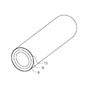
また、光触媒技術の樹脂製配管部材への応用としては、図3に示す様な住宅用の酸化チタン光触媒被覆配管が提案されている(例えば、特許文献2参照)。この方法は合成樹脂からなる内層管8と弾性合成樹脂からなる外層管9より構成されるパイプにおいて、前記外層管9の外表面に酸化チタン光触媒層10を被覆するものであり、遮音性を有すると共に最外層の汚れを防止し、キズの発生を防ぎ、耐候性に優れるパイプを提供するものであった。
In addition, as an application of the photocatalyst technology to a resin piping member, a titanium oxide photocatalyst-coated piping for housing as shown in FIG. 3 has been proposed (for example, see Patent Document 2). In this method, a pipe composed of an
しかしながら、前記合成樹脂からなるパイプ表面に光触媒を直接被覆した場合、光触媒による酸化分解作用によってパイプ自体が酸化劣化を受けてしまい、長期使用すると酸化劣化により強度が低下し、パイプが破損する恐れがあった。 However, when the photocatalyst is directly coated on the surface of the pipe made of the synthetic resin, the pipe itself is subject to oxidative degradation due to the oxidative decomposition action of the photocatalyst, and the strength may decrease due to the oxidative degradation and the pipe may be damaged after long-term use. there were.
本発明は、以上のような従来技術の問題点に鑑みなされたものであり、その目的とするところは、屋外での使用において耐候性に優れ、防汚性に富むことから長期使用を可能にした樹脂製配管部材を提供するものである。 The present invention has been made in view of the above-described problems of the prior art, and the object of the present invention is to provide long-term use since it has excellent weather resistance and excellent antifouling properties when used outdoors. Provided is a resin-made piping member.
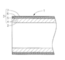
上記課題を解決するための本発明の樹脂製配管部材の構成を図1、図2に基づいて説明すると、本発明の樹脂製配管部材1は母材2の外表面に内側から順に少なくとも紫外線遮蔽層5、中間層6および光触媒層7が形成された樹脂製配管部材1であって、紫外線遮蔽層5が紫外線吸収剤及び/または紫外線散乱剤を含む樹脂から形成され、また、中間層6が無機系材質を必須成分として形成されていることを第一の特徴とする。また、母材2の外表面に、内側から順に、粘着層4、紫外線遮蔽層5、中間層6および光触媒層7から形成されるフィルム3を被覆してなることを第二の特徴とする。また、母材2のJIS B0601による外表面の表面粗さ(Rz)が10μm以下であることを第三の特徴とする。また、母材2のJIS K7171による曲げ弾性率が500MPa以上であることを第四の特徴とする。また、母材2の線膨張係数が1.3×10⁻⁴/℃以下であることを第五の特徴とする。また、キセノンアーク光源の野外暴露試験装置(ウェザーメーター)による1800時間(照射エネルギー405,000KJ/m2、野外暴露1.5年相当)の強制劣化試験後の母材2のJIS K7113による引張り伸び率の保持率が90%以上で、且つJIS K7110によるノッチ付きアイゾット衝撃値の保持率が70%以上であることを第六の特徴とする。
The structure of the resin piping member of the present invention for solving the above problems will be described with reference to FIGS. 1 and 2. The
本発明において光触媒層7とは、紫外線が照射されるとその紫外線を吸収することで活性化し、その表面が高度に親水化することで、水に非常に濡れ易くなり、塵埃等の汚れが付き難い性質を持っており、且つ、汚れが一時的に付着しても雨水等により容易に洗い流される特徴を有する層のことである。光触媒としては、例えばアナターゼ型酸化チタン、ルチル型酸化チタン、ブルッカイト型酸化チタン、酸化亜鉛、酸化錫、酸化第二鉄、三酸化二ビスマス、三酸化タングステン、チタン酸ストロンチウム等が挙げられる。また、光触媒層はその他に紫外線照射によらず常にその表面が親水化しているものでもよく、例えば一般式R1 nSi(OR2)4−n〔n=0〜3の整数、R1、R2は一価の炭化水素基〕で表されるオルガノシランの加水分解縮重合物において、そのSiの側鎖にOH基を含有させて極度に親水性を高めたシラノール基含有シリコーンレジン等が挙げられる。 In the present invention, the photocatalyst layer 7 is activated by absorbing ultraviolet rays when irradiated with ultraviolet rays, and its surface becomes highly hydrophilic, so that it becomes very easy to get wet with water, and dirt such as dust is attached. It is a layer having characteristics that are difficult and that is easily washed away by rainwater or the like even if dirt is temporarily attached. Examples of the photocatalyst include anatase type titanium oxide, rutile type titanium oxide, brookite type titanium oxide, zinc oxide, tin oxide, ferric oxide, dibismuth trioxide, tungsten trioxide, strontium titanate and the like. In addition, the photocatalyst layer may be one whose surface is always hydrophilized irrespective of ultraviolet irradiation, for example, a general formula R 1 n Si (OR 2 ) 4-n [n = 0 to 3, an integer of R 1 , In the hydrolyzed polycondensation product of an organosilane represented by R 2 is a monovalent hydrocarbon group], a silanol group-containing silicone resin or the like having extremely enhanced hydrophilicity by containing an OH group in the side chain of Si Can be mentioned.
また、本発明において中間層6とは、光触媒層7の酸化分解作用から母材2や樹脂を含む紫外線遮蔽層5の劣化を防止するために光触媒層7の内側に形成されるもので、光触媒層7が酸化分解作用を示さない場合であっても、無機成分からなる光触媒層7と有機成分からなる紫外線遮蔽層5との接着性を向上させる点から設けられるものである。この様な中間層6としては無機系材質を必須成分とし、光触媒層7と紫外線遮蔽層5の接着性を向上させるものであれば、特に限定されるものではなく、例えばシリカ、アルミナ、酸化インジウム、酸化ジルコニウム等の無機系材質からなる真空堆積膜、又はこれらの無機系材質からなるアルコキシド化合物等を主成分とする塗布膜、シランカップリング剤等が挙げられる。また、光触媒層7と紫外線遮蔽層5との接着性を向上させるものとしては有機−無機複合傾斜膜等が好ましい。これは有機高分子化合物と金属酸化物系化合物が化学結合した複合体で、金属成分の含有率が膜の厚み方向に連続的に変化する成分傾斜構造を有し、光触媒層に接触する面の金属成分の含有率が100%に、また、紫外線遮蔽層に接する面の有機高分子化合物成分の含有率が100%になるように形成されているので、特に光触媒層7と紫外線遮蔽層5の接着性を向上させることができる。
In the present invention, the intermediate layer 6 is formed inside the photocatalyst layer 7 in order to prevent the
また、本発明において紫外線遮蔽層5とは、紫外線吸収剤及び/または紫外線散乱剤を含有する樹脂から形成され、紫外線遮蔽効果を発揮するものであり、太陽光等からの紫外線が光触媒層によって十分吸収されない場合でも、透過してきた紫外線を吸収または散乱することにより遮蔽し、母材2の紫外線劣化を防ぐ点から設けられるものである。紫外線吸収剤としては、高エネルギーを持つ紫外線を吸収し、低エネルギーに転換してラジカルの発生を抑え、樹脂の劣化を防止するものであって、一般にサリシレート系樹脂、ベンゾフェノン系樹脂、ベンゾトリアゾール系樹脂、置換アクリロニトリル系樹脂等が挙げられる。紫外線散乱剤としては、紫外線を散乱させることによって紫外線遮蔽効果をもたらすものであり、主に金属酸化物粉末などの無機材料が挙げられる。紫外線吸収剤及び/または紫外線散乱剤を含ませる樹脂としては、アクリル系樹脂、ポリスチレンやABS樹脂等のスチレン系樹脂、ポリエチレンやポリプロピレン等のオレフィン系樹脂、ポリエチレンテレフタレートやポリエチレンナフタレート等のポリエステル系樹脂、ポリ塩化ビニル系樹脂、ポリカーボネート樹脂等が挙げられる。尚、紫外線吸収剤と紫外線散乱剤は単独使用または両者を併用しても構わない。
Further, in the present invention, the
また、本発明において母材2の外表面に上記各層を形成する方法は、例えば上記各層が形成されたフィルム3を被覆する方法や、スプレーコーティング等の湿式塗布法で設ける方法、スパッタリング法、イオンプレーティング法等の真空製膜法等が挙げられる。特にフィルム3を被覆することで、各層が均質で欠陥なく形成できることや母材2の製造工程が簡略化されると共に、配管部材を設置した後でもフィルム3を必要に応じて被覆するなど作業の自由度が上がることから、フィルム3を被覆する方法が好適である。
In the present invention, the method for forming each layer on the outer surface of the
また、本発明において粘着層4とは、フィルム3の一方の面に形成されており、母材2とフィルム3とを接着させて被覆するために設けられた層で、粘着作用があるものであれば特に限定されるものではない。粘着層4としては一般に使用されるアクリル系、ウレタン系、シリコーン系、ゴム系粘着剤等を使用することができ、好ましくは紫外線吸収剤や紫外線散乱剤を含有させることによって耐候性を向上させたものを使用することが好適である。
In the present invention, the pressure-sensitive
本発明の母材2のJIS B0601による外表面の表面粗さ(Rz)は10μm以下にする必要があり、0.1〜5μmの範囲にすることがより好ましい。母材2の外表面にフィルム3を被覆する場合、粘着層4の変形によって母材2の外表面の凹凸への追従を可能にさせ、接着面積を十分に確保させ、且つ、粘着層4が母材2の外表面の隙間に入り込む際に空気抜けがしやすく、空隙の発生等による接着不良が起こりにくくするために表面粗さは10μm以下にする必要がある。
The surface roughness (Rz) of the outer surface according to JIS B0601 of the
また、母材2の曲げ弾性率は500MPa以上であることが必要であり、900MPa〜20GPaの範囲であることがより好ましい。母材2の外表面にフィルム3を被覆する場合、運搬や施工を行う場合に曲がりにくくさせ、長期使用をする場合にも変形や撓みを生じにくくさせることで、被覆したフィルム3の追従を容易にし、剥がれにくくさせるために、母材2の曲げ弾性率は500MPa以上であることが必要である。さらに、屋外で40℃を越す雰囲気中での使用も想定され、気温が高くなることによる曲げ弾性率の低下を考慮すると、母材2の曲げ弾性率は900MPa以上であることが必要であり、母材2の曲げ弾性率が高くなりすぎると樹脂は脆くなる傾向があるため、配管部材として好適に使用するためには母材2の曲げ弾性率は20GPa以下であることが好ましい。
Moreover, the bending elastic modulus of the
また、母材2の線膨張係数は1.3×10⁻⁴/℃以下であることが必要であり、さらに0.1×10−4/℃〜1.3×10−4/℃の範囲であることがより好ましい。母材2の外表面にフィルム3を被覆した場合、直射日光にさらされる環境下や高温の水が内部を流れる環境下において、母材2の熱による膨張、収縮に伴った寸法変化を小さくさせ、これによって被覆したフィルム3の追従を容易にし、剥がれにくくさせるために、母材2の線膨張係数は1.3×10−4/℃以下であることが必要である。また、母材2の線膨張係数が低くなりすぎると被覆したフィルム3が母材2と比較して熱による寸法変化が大きくなり、フィルム3の延伸の差が生じるため、母材2の線膨張係数は0.1×10−4/℃以上であることが好ましい。
The linear expansion coefficient of the
さらに、キセノンアーク光源の野外暴露試験装置(ウェザーメーター)による1800時間(照射エネルギー405,000KJ/m2、野外暴露1.5年相当)の強制劣化試験後の母材2のJIS K7113による引張り伸び率の保持率が90%以上で、且つJIS K7110によるノッチ付きアイゾット衝撃値の保持率が70%以上であることが好ましい。屋外での使用において母材2の紫外線劣化が起きやすく、配管の性能上特に樹脂の脆化による破損の恐れがあるため、脆化の程度を示す物性値として引張り伸び率の保持率が90%以上、アイゾット衝撃値の保持率が70%以上にする必要がある。
Further, tensile elongation of
母材2に使用される原料としては、管、管継手、バルブおよびバルブ駆動部材等の配管部材に好適に使用されるものであれば特に限定されるものではなく、例えば、ポリエチレン、ホモ型ポリプロピレン、ランダム共重合型ポリプロピレン等のオレフィン系樹脂、硬質ポリ塩化ビニル、塩素化ポリ塩化ビニル、ポリビニリデンフルオライド、ポリテトラフルオロエチレン等のハロゲン系含有樹脂、ポリカーボネート、アクリル系樹脂、アクリロニトリルブタジエンスチレン樹脂等が挙げられる。また、必要に応じて、これらの樹脂の成形性、熱安定性、耐候性を向上させるため、例えば、安定剤、加工補助剤、酸化防止剤、帯電防止剤、紫外線吸収剤、光安定剤、滑剤、充填剤、難燃剤、顔料、染料等を配合したものでもよい。
The raw material used for the
本発明は、以上説明した構造になっているので、以下の様な優れた効果が得られる。
(1)光触媒層と母材の間に中間層を設けることにより、母材に対する光触媒の酸化劣化作用を抑制させ、且つ、光触媒層及び紫外線吸収層での紫外線を遮蔽させることにより紫外線劣化を抑えることができるため、従来よりも40%〜80%長く耐候性を保持することができる。
(2)光触媒層を設けることにより光触媒の酸化分解作用または親水化作用によって、長期間に亘って防汚性を保持することができる。
(3)母材に内側から順に粘着層、紫外線遮蔽層、中間層および光触媒層から形成されるフィルムを被覆することによって、各層が欠陥なく均質に形成できると共に、製造工程が簡略化でき、配管部材を設置した後でも必要に応じてフィルムを被覆することで容易に耐候性、防汚性の効果を得ることができる。
(4)母材の外表面の表面粗さ(Rz)を10μm以下にすることにより、被覆するフィルムと母材の接着性を向上させ、長期間に亘ってフィルムが剥がれない様にすることができる。
(5)母材の曲げ弾性率が500MPa以上であると、母材の変形に対して被覆されたフィルムが追従しやすく、長期間に亘ってフィルムが剥がれない様にすることができる。
(6)母材の線膨張係数が1.3×10⁻⁴以下であると、母材の熱による膨張に対して被覆されたフィルムが追従しやすく、長期間に亘ってフィルムが剥がれない様にすることができる。
(7)キセノンアーク光源の野外暴露試験装置(ウェザーメーター)による1800時間(照射エネルギー405,000KJ/m2、野外暴露1.5年相当)の強制劣化試験後の母材のJIS K7113による引張り伸び率の保持率が90%以上で、且つJIS K7110によるノッチ付きアイゾット衝撃値の保持率が70%以上であると、屋外における長期使用の際に母材の樹脂の脆化を抑えることができる。
Since the present invention has the structure described above, the following excellent effects can be obtained.
(1) By providing an intermediate layer between the photocatalyst layer and the base material, the oxidative deterioration action of the photocatalyst on the base material is suppressed, and the UV deterioration is suppressed by shielding the UV light in the photocatalyst layer and the UV absorption layer. Therefore, the weather resistance can be maintained for 40% to 80% longer than conventional.
(2) By providing the photocatalyst layer, antifouling properties can be maintained over a long period of time by the oxidative decomposition action or the hydrophilization action of the photocatalyst.
(3) By covering the base material with a film formed from an adhesive layer, an ultraviolet shielding layer, an intermediate layer and a photocatalyst layer in order from the inside, each layer can be formed uniformly without defects, and the manufacturing process can be simplified, and piping Even after the members are installed, the effects of weather resistance and antifouling properties can be easily obtained by covering the film as necessary.
(4) By making the surface roughness (Rz) of the outer surface of the
(5) When the flexural modulus of the base material is 500 MPa or more, the coated film can easily follow the deformation of the base material, and the film can be prevented from peeling off over a long period of time.
(6) When the linear expansion coefficient of the base material is 1.3 × 10 −4 or less, the coated film easily follows the expansion of the base material due to heat, and the film does not peel off over a long period of time. Can be.
(7) Tensile elongation of the base material according to JIS K7113 after a forced deterioration test of 1800 hours (irradiation energy: 405,000 KJ / m 2 , equivalent to 1.5 years of field exposure) using a xenon arc light source field exposure test equipment (weather meter) When the retention rate of the ratio is 90% or more and the retention rate of the notched Izod impact value according to JIS K7110 is 70% or more, embrittlement of the base resin can be suppressed during long-term outdoor use.
次に、本発明の実施例について、図1及び図2を用いてさらに詳細に説明するが、本発明が本実施例になんら限定されないことは言うまでもない。 Next, examples of the present invention will be described in more detail with reference to FIGS. 1 and 2. Needless to say, the present invention is not limited to the examples.
図1は本発明の一実施例を示す管の斜視図である。図2は図1のA−A’線に沿う縦断面図である。 FIG. 1 is a perspective view of a tube showing an embodiment of the present invention. FIG. 2 is a longitudinal sectional view taken along line A-A ′ of FIG. 1.
1は樹脂製配管部材の一つである管である。管1は母材2の外表面にフィルム3を被覆したもので、その各々の構成は下記の通りである。(図2参照)
2は母材である硬質ポリ塩化ビニル製の管である。母材2の外径は60mm、肉厚は4.1mm、また、外表面の表面粗さ(Rz)は2μmに形成されている。
2 is a pipe made of hard polyvinyl chloride as a base material. The
3は母材2の外表面に被覆されているフィルムである。フィルム3は、内側から順に粘着層4、紫外線遮蔽層5、中間層6、光触媒層7から形成されている。
A
粘着層4は、母材2の外表面にフィルム3を接着させるもので、紫外線吸収剤であるベンゾフェノン系紫外線吸収剤を含有するアクリル系粘着剤からなり、膜厚は25μmに形成されている。なお、粘着層4の膜厚は3〜100μmの範囲に設定することが好適である。
The pressure-
紫外線遮蔽層5は、紫外線吸収剤であるベンゾフェノン系紫外線吸収剤を含有したポリエチレンテレフタレートからなり、膜厚は50μmに形成されている。紫外線遮蔽層5の膜厚は10〜500μmの範囲に設定することが好適である。
The
中間層6は、無機−有機複合傾斜膜からなるものであり、これは有機高分子化合物であるアクリル系ポリマーと金属酸化物系化合物である酸化チタンとが化学的に結合した複合体で、酸化チタンの含有率が膜の厚み方向に連続的に変化する成分傾斜構造を有し、光触媒層7に接触する面の酸化チタンの含有率が100%に、また、紫外線遮蔽層5に接する面のアクリル系ポリマーの含有率が100%になるように形成されている。中間層6の膜厚は80nmに形成されている。なお、中間層6の膜厚は40nm〜5μmの範囲に設定することが好適である。
The intermediate layer 6 is composed of an inorganic-organic composite gradient film, which is a composite in which an acrylic polymer that is an organic polymer compound and titanium oxide that is a metal oxide compound are chemically bonded. It has a component gradient structure in which the titanium content changes continuously in the thickness direction of the film, the titanium oxide content on the surface in contact with the photocatalyst layer 7 is 100%, and the surface in contact with the
光触媒層7は、アナターゼ型酸化チタンを含有する無機系バインダーからなるものであり、光触媒層7の膜厚は50nmに形成されている。なお、光触媒層7の膜厚は10nm〜5μmの範囲に設定することが好適である。 The photocatalyst layer 7 is made of an inorganic binder containing anatase-type titanium oxide, and the film thickness of the photocatalyst layer 7 is 50 nm. The film thickness of the photocatalyst layer 7 is preferably set in the range of 10 nm to 5 μm.
なお、本実施例では母材2として管を使用しているが配管部材であればいずれでもよく、管継手、バルブおよびバルブ駆動部材等を使用してもよい。このバルブ駆動部材とはハンドル、ギアボックス等のバルブの動作に必要な部品全てを指すものである。
In this embodiment, a pipe is used as the
また、本実施例では樹脂製配管部材である管1は、母材2の外表面にフィルム3が被覆されているが、フィルム3は上記各層が均質で欠陥のない状態で形成されているため、フィルム3を被覆することにより、管1の各層を均質で欠陥なく形成できると共に、製造工程が簡略化でき、配管部材を設置した後でも必要に応じてフィルムを被覆することで容易に耐候性、防汚性の効果を得ることができる。各層を形成する方法はフィルム3を被覆する方法以外のものでもよく、例えばスプレーコーティング等の湿式塗布法で設ける方法や、スパッタリング法、イオンプレーティング法等の真空製膜法等が挙げられる。
Further, in the present embodiment, the
次に、本実施例の管1に紫外線を含む太陽光、蛍光灯等が照射された場合の紫外線劣化防止作用を説明する。
Next, a description will be given of the UV deterioration preventing action when the
まず、光触媒層7に含まれる酸化チタンによって390nm付近の波長領域にある紫外線が吸収される。次に、光触媒層7を透過してきた紫外線に対して紫外線遮蔽層5が紫外線吸収剤の場合は紫外線を吸収し、紫外線散乱剤の場合は紫外線を散乱させる。このことから、光触媒層7と紫外線遮蔽層5により紫外線遮蔽層5の内側にある母材2には紫外線が届かない構造となっている。また、紫外線によって光触媒層7が活性化し酸化分解作用が起こるが、中間層6が光触媒層7の下に設けられていることから、酸化分解作用が紫外線遮蔽層5や母材2には作用しないものとなっている。以上の作用によって紫外線を遮蔽するため、紫外線劣化が起こりやすい屋外で母材2に起こる紫外線劣化を防止し、長期使用を可能にすることができる。
First, ultraviolet rays in the wavelength region near 390 nm are absorbed by the titanium oxide contained in the photocatalytic layer 7. Next, when the ultraviolet
次に、本実施例の管1の防汚作用について説明する。
Next, the antifouling action of the
光触媒層7に含まれる酸化チタンに紫外線が当たることによって、親水化作用が起こり、管1の表面が高度に親水化することで、非常に水に濡れ易くなり、塵埃等の汚れが付き難くなり、且つ、汚れが一時的に付着しても雨水等により容易に洗い流されるため、セルフクリーニング効果を得ることができる。また、同時に酸化分解作用が起こり、抗菌、藻類の発生防止、付着油の分解などの効果も得ることができる。以上の作用によって長期に亘って防汚性を維持することができる。
When the titanium oxide contained in the photocatalyst layer 7 is exposed to ultraviolet rays, a hydrophilizing action occurs, and the surface of the
次に、本発明の樹脂製配管部材である管の屋外での長期使用の耐候性および防汚性を確認するための評価試験を行った。その評価試験方法を以下に示す。 Next, the evaluation test for confirming the weather resistance and antifouling property of the pipe | tube which is the resin-made piping members of this invention for the long term use outdoors was done. The evaluation test method is shown below.
(1)母材の外表面の表面粗さ
JIS B0601に準拠し、母材の外表面の表面粗さとして管軸方向の最大高さ粗さ(Rz)を測定した。
(1) Surface roughness of outer surface of base material In accordance with JIS B0601, the maximum height roughness (Rz) in the tube axis direction was measured as the surface roughness of the outer surface of the base material.
(2)母材の曲げ試験
JIS K7171に準拠し、母材から曲げ試験片を管軸方向に沿って切り出し、母材の曲げ弾性率を測定した。
(2) Bending test of base material Based on JIS K7171, the bending test piece was cut out from the base material along the pipe-axis direction, and the bending elastic modulus of the base material was measured.
(3)母材の線膨張係数
母材から試験片を10mm×20mm×4mmで切り出し、測定時の昇温による後収縮の誤差を除くため、前処理として測定最高温度+10℃で1時間アニーリング処理を行った。測定時の昇温速度は2℃/minで、試料長さの変位量をプロットし、測定した温度と変位量の関係から線膨張係数を算出した。
(3) Linear expansion coefficient of base material A test piece is cut out from a base material at 10 mm x 20 mm x 4 mm, and an annealing treatment is performed for 1 hour at the maximum measured temperature + 10 ° C as a pretreatment in order to eliminate an error in post-shrinkage due to a temperature rise during measurement. Went. The temperature increase rate at the time of measurement was 2 ° C./min, the amount of displacement of the sample length was plotted, and the linear expansion coefficient was calculated from the relationship between the measured temperature and the amount of displacement.
(4)耐候性試験
母材から引張り試験片、ノッチ付きアイゾット衝撃試験片を管軸方向に沿って切り出し、後記の実験例の条件にてフィルムを被覆し、キセノンアーク光源の野外暴露試験装置(ウェザーメーター)により、照射時間600hr(照射エネルギー135,000kJ/m2、野外暴露6ヶ月相当)、1800hr(照射エネルギー405,000kJ/m2、野外暴露1.5年相当)で強制劣化試験を行った。その後、試験片の外観の評価と純水接触角試験を行い、被覆層を剥離した後、引張り試験、アイゾット衝撃試験を行った。
(4) Weather resistance test A tensile test piece and a notched Izod impact test piece are cut out from the base material along the tube axis direction, covered with a film under the conditions of the experimental example described below, and a field exposure test device for a xenon arc light source ( Using a weather meter, a forced deterioration test was conducted at an irradiation time of 600 hr (irradiation energy of 135,000 kJ / m 2 , equivalent to 6 months of field exposure), and 1800 hr (irradiation energy of 405,000 kJ / m 2 , equivalent to 1.5 years of outdoor exposure). It was. Thereafter, the appearance of the test piece was evaluated and a pure water contact angle test was performed. After the coating layer was peeled off, a tensile test and an Izod impact test were performed.
(4−1)外観の評価
強制劣化試験後の試験片について、外表面の割れ、変色、被覆した層の剥離状況などの異常の有無を目視により以下の様に評価した。
◎:劣化が全く見られない
○:わずかに変色が見られる
△:変色が見られる
×:変色及び劣化が見られる
(4-1) Appearance Evaluation The test piece after the forced deterioration test was visually evaluated for the presence or absence of abnormalities such as cracks on the outer surface, discoloration, and peeling of the coated layer.
◎: No deterioration is observed ○: Discoloration is slightly observed Δ: Discoloration is observed ×: Discoloration and deterioration are observed
(4−2)純水接触角試験
強制劣化試験後の試験片について外表面を油や埃等の汚れがない様に洗浄、乾燥した後、温度20℃、湿度50%の雰囲気で6時間状態調整をした後、純水を約1ml滴下する。その後、10分後の接触角(固体表面上にできる液滴の接触部分がつくる角度)をカメラによる撮影や接触角計にて測定し、以下の様に評価した。
◎:純水接触角が15°未満
○:純水接触角が15°以上25°未満
△:純水接触角が25°以上50°未満
×:純水接触角が50°以上
−:強制劣化試験による劣化が酷かったため測定せず
(4-2) Pure water contact angle test The test piece after the forced deterioration test is cleaned and dried so that the outer surface is free from dirt such as oil and dust, and then in an atmosphere of 20 ° C and 50% humidity for 6 hours. After adjustment, about 1 ml of pure water is dropped. Thereafter, the contact angle after 10 minutes (the angle formed by the contact portion of the liquid droplet formed on the solid surface) was measured by photographing with a camera or a contact angle meter, and evaluated as follows.
◎: Pure water contact angle is less than 15 ° ○: Pure water contact angle is 15 ° or more and less than 25 ° △: Pure water contact angle is 25 ° or more and less than 50 ° ×: Pure water contact angle is 50 ° or more −: Forced deterioration Not measured due to severe degradation due to testing
(4−3)引張り試験
強制劣化試験後の試験片について、JIS K7113に準拠し、引張り強度、引張り伸び率を測定した。
(4-3) Tensile test The test piece after the forced deterioration test was measured for tensile strength and tensile elongation according to JIS K7113.
(4−4)ノッチ付きアイゾット衝撃試験
強制劣化試験後の試験片について、JIS K7110に準拠し、ノッチ付きアイゾット衝撃強度を測定した。
(4-4) Notched Izod Impact Test The notched Izod impact strength of the test piece after the forced deterioration test was measured according to JIS K7110.
(4−5)屋外使用時の推定寿命
強制劣化試験において、経験上特に物性値の低下が見られる引張り伸び率において保持率が50%以下になった時間を屋外使用における寿命と定義し、引張り伸び率と試験時間の関係から屋外使用時の推定寿命をメーカーカタログ値及びアレニウスプロットから算出した。推定寿命値は何も被覆していない樹脂製管(後記比較例1乃至4)の寿命を1として相対的な値を求めた。
(4-5) Estimated life in outdoor use In the forced deterioration test, the time when the retention rate becomes 50% or less in the tensile elongation at which a decrease in physical property value is seen from experience is defined as the life in outdoor use. From the relationship between the elongation rate and the test time, the estimated lifetime during outdoor use was calculated from the manufacturer catalog value and the Arrhenius plot. The estimated life value was obtained by setting the life of a resin pipe (No. Comparative Examples 1 to 4 described later) that is not coated to 1 as a relative value.
(5)水圧破壊試験
フィルムを被覆した1mの管に対し、上記の強制劣化試験を実施し、配水用ポリエチレン協会規格PWA001に基づいて23±2℃の雰囲気中で、管内部に破壊するまで一定の水圧で加圧を続け管が破壊した時点の圧力の最大値を測定した。
(5) Water pressure fracture test The above-mentioned forced deterioration test is carried out on a 1m pipe covered with a film, and it is constant until it breaks inside the pipe in an atmosphere of 23 ± 2 ° C based on the water distribution polyethylene association standard PWA001. The maximum value of the pressure at the time when the tube was broken was measured by continuing the pressurization with the water pressure.
(6)屋外暴露試験
フィルムを被覆した1mの管を、屋外に静置し、半年後の外観の変化を以下の基準で評価した。
◎:劣化が全く見られない
○:わずかに変色が見られる
△:変色が見られる
×:変色及び劣化が見られる
(6) Outdoor exposure test A 1 m tube covered with a film was left outdoors, and the change in appearance after six months was evaluated according to the following criteria.
◎: No deterioration is observed ○: Discoloration is slightly observed Δ: Discoloration is observed ×: Discoloration and deterioration are observed
(7)繰り返し荷重試験
フィルムを被覆した1mの管の端面の一方を固定し、他方の端面に500Nの荷重を1分間かけて曲げ、その後荷重をかけるのをやめて元に戻す。以上の操作を繰り返し20回行い、被覆した光触媒フィルムの剥がれの程度を以下の基準で評価した。
◎:異常なし
○:一部剥がれが見られる
△:かなり剥がれが見られる
×:完全に剥がれた
(7) Repeated load test One end face of a 1 m tube covered with a film is fixed, a load of 500 N is bent on the other end face over 1 minute, and then the load is stopped and returned to its original state. The above operation was repeated 20 times, and the degree of peeling of the coated photocatalyst film was evaluated according to the following criteria.
◎: No abnormality ○: Partial peeling is observed Δ: Exfoliation is observed considerably ×: Completely peeled
(8)ヒートサイクル試験
フィルムを被覆した20cmの管を、80℃に調整した恒温槽に入れ、1時間加熱し、その後室温にて常温まで放冷する。以上の加熱、放冷を100回繰り返し、被覆した光触媒フィルムの剥がれの程度を以下の基準で評価した。
◎:異常なし
○:一部剥がれが見られる
△:かなり剥がれが見られる
×:完全に剥がれた
(8) Heat cycle test A 20 cm tube coated with a film is placed in a thermostat adjusted to 80 ° C., heated for 1 hour, and then allowed to cool to room temperature at room temperature. The above heating and cooling were repeated 100 times, and the degree of peeling of the coated photocatalytic film was evaluated according to the following criteria.
◎: No abnormality ○: Partial peeling is observed Δ: Exfoliation is observed considerably ×: Completely peeled
[実験例1]
外表面の表面粗さ(Rz)が2μmの外径60mm、肉厚4.1mmの硬質ポリ塩化ビニル製の管(母材管)の外表面に、内側から順にアクリル系粘着剤からなる膜厚25μmの粘着層、紫外線吸収剤を含むポリエチレンテレフタレート樹脂からなる膜厚50μmの紫外線遮蔽層、有機−無機複合傾斜膜からなる膜厚樹脂80nmの中間層、酸化チタン光触媒からなる膜厚0.2μmの光触媒層より形成されるフィルムを被覆して各種試験を行った。試験結果を表1に示す。
[Experimental Example 1]
A film thickness composed of an acrylic adhesive on the outer surface of a hard polyvinyl chloride tube (base material tube) having a surface roughness (Rz) of 2 μm and an outer diameter of 60 mm and a wall thickness of 4.1 mm. 25 μm adhesive layer, 50 μm thick UV shielding layer made of polyethylene terephthalate resin containing UV absorber, 80 nm thick resin layer made of organic-inorganic composite gradient film, 0.2 μm thick film made of titanium oxide photocatalyst Various tests were conducted by covering a film formed from the photocatalyst layer. The test results are shown in Table 1.
[実験例2]
外表面の表面粗さ(Rz)が3μmの外径60mm、肉厚4.1mmの硬質ポリ塩化ビニル製管の外表面に、内側から順にアクリル系粘着剤からなる膜厚25μmの粘着層、紫外線吸収剤を含むアクリル樹脂からなる膜厚75μmの紫外線遮蔽層、シリコーン系樹脂からなる膜厚2μmの中間層、酸化チタン光触媒からなる膜厚0.2μmの光触媒層より形成されるフィルムを被覆して各種試験を行った。試験結果を表1に示す。
[Experiment 2]
On the outer surface of a hard polyvinyl chloride tube having an outer surface with a surface roughness (Rz) of 3 μm and an outer diameter of 60 mm and a wall thickness of 4.1 mm, an adhesive layer having a film thickness of 25 μm made of an acrylic adhesive in order from the inside, UV A film formed by an ultraviolet shielding layer having a film thickness of 75 μm made of an acrylic resin containing an absorbent, an intermediate layer having a film thickness of 2 μm made of a silicone resin, and a photocatalyst layer having a thickness of 0.2 μm made of a titanium oxide photocatalyst is coated. Various tests were conducted. The test results are shown in Table 1.
[実験例3]
実験例1において、母材管を外表面の表面粗さ(Rz)が2μmの外径63mm、肉厚5.8mmのホモ型ポリプロピレン製に変え、同様にして各種試験を行った。試験結果を表1に示す。
[Experiment 3]
In Experimental Example 1, the base tube was changed to a homopolypropylene having an outer surface with a surface roughness (Rz) of 2 μm and an outer diameter of 63 mm and a wall thickness of 5.8 mm, and various tests were performed in the same manner. The test results are shown in Table 1.
[実験例4]
実験例1において、母材管を外表面の表面粗さ(Rz)が14μmの外径60mm、肉厚4.1mmの硬質ポリ塩化ビニル製に変え、同様にして各種試験を行った。試験結果を表1に示す。
[Experimental Example 4]
In Experimental Example 1, the base tube was changed to a hard polyvinyl chloride having an outer surface with a surface roughness (Rz) of 14 μm and an outer diameter of 60 mm and a wall thickness of 4.1 mm, and various tests were performed in the same manner. The test results are shown in Table 1.
[実験例5]
実験例1において、母材管を外表面の表面粗さ(Rz)が1μmの外径58mm、肉厚4.0mmの軟質ポリ塩化ビニル製に変え、同様にして各種試験を行った。試験結果を表1に示す。
[Experimental Example 5]
In Experimental Example 1, the base tube was changed to a soft polyvinyl chloride having an outer surface with a surface roughness (Rz) of 1 μm and an outer diameter of 58 mm and a wall thickness of 4.0 mm, and various tests were performed in the same manner. The test results are shown in Table 1.
[実験例6]
実験例1において、母材管を外表面の表面粗さ(Rz)が2μmの外径63mm、肉厚5.8mmのランダム共重合型ポリプロピレン製に変え、同様にして各種試験を行った。試験結果を表1に示す。
[Experimental Example 6]
In Experimental Example 1, the base tube was changed to a random copolymer type polypropylene having an outer surface with a surface roughness (Rz) of 2 μm and an outer diameter of 63 mm and a wall thickness of 5.8 mm, and various tests were performed in the same manner. The test results are shown in Table 1.
[比較例1]
外表面に何も被覆されていない、外表面の表面粗さ(Rz)が1μmの外径60mm、肉厚4.1mmの硬質ポリ塩化ビニル製の管について各種試験を行った。試験結果を表1に示す。
[Comparative Example 1]
Various tests were conducted on tubes made of hard polyvinyl chloride having an outer surface with a surface roughness (Rz) of 1 μm and an outer diameter of 60 mm and a wall thickness of 4.1 mm. The test results are shown in Table 1.
[比較例2]
外表面に何も被覆されていない、外表面の表面粗さ(Rz)が2μmの外径63mm、肉厚5.8mmのホモ型ポリプロピレン製の管について各種試験を行った。試験結果を表1に示す。
[Comparative Example 2]
Various tests were conducted on homopolypropylene tubes having an outer surface with a surface roughness (Rz) of 2 μm and an outer diameter of 63 mm and a wall thickness of 5.8 mm. The test results are shown in Table 1.
[比較例3]
外表面に何も被覆されていない、外表面の表面粗さ(Rz)が1μmの外径58mm、肉厚4.0mmの軟質ポリ塩化ビニル製の管について各種試験を行った。試験結果を表1に示す。
[Comparative Example 3]
Various tests were conducted on a tube made of soft polyvinyl chloride having an outer surface with a surface roughness (Rz) of 1 μm and an outer diameter of 58 mm and a wall thickness of 4.0 mm. The test results are shown in Table 1.
[比較例4]
外表面に何も被覆されていない、外表面の表面粗さ(Rz)が3μmの外径63mm、肉厚5.8mmのランダム共重合型ポリプロピレン製の管について各種試験を行った。試験結果を表1に示す。
[Comparative Example 4]
Various tests were conducted on a random copolymer type polypropylene tube having an outer surface with a surface roughness (Rz) of 3 μm and an outer diameter of 63 mm and a wall thickness of 5.8 mm. The test results are shown in Table 1.
[比較例5]
外表面の表面粗さ(Rz)が3μmの外径60mm、肉厚4.1mmの硬質ポリ塩化ビニル製の管の外表面に酸化チタン光触媒からなる膜厚1μmの光触媒層のみを形成して各種試験を行った。試験結果を表1に示す。
[Comparative Example 5]
Only a photocatalyst layer having a thickness of 1 μm made of titanium oxide photocatalyst is formed on the outer surface of a hard polyvinyl chloride tube having an outer diameter of 3 μm and an outer diameter of 60 mm and a wall thickness of 4.1 mm. A test was conducted. The test results are shown in Table 1.
[比較例6]
外表面の表面粗さ(Rz)が1μmの外径60mm、肉厚4.1mmの硬質ポリ塩化ビニル製の管の外表面に、内側から順にアクリル系粘着剤からなる膜厚25μmの粘着層、有機−無機複合傾斜膜からなる膜厚樹脂80nmの中間層、酸化チタン光触媒からなる膜厚0.2μmの光触媒層より形成されるフィルムを被覆して各種試験を行った。試験結果を表1に示す。
[Comparative Example 6]
On the outer surface of a hard polyvinyl chloride tube having an outer diameter of 60 mm and a wall thickness of 4.1 mm with an outer surface roughness (Rz) of 1 μm, an adhesive layer having a film thickness of 25 μm made of an acrylic adhesive in order from the inside, Various tests were carried out by covering a film formed of an intermediate layer made of an organic-inorganic composite gradient film having a film thickness of 80 nm and a photocatalyst layer having a thickness of 0.2 μm made of a titanium oxide photocatalyst. The test results are shown in Table 1.
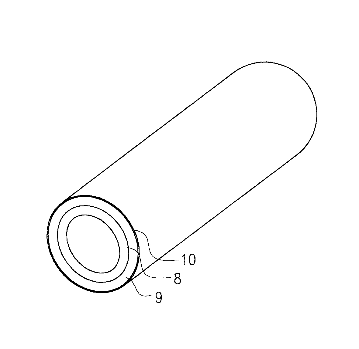
表1から分かるように、実験例で得られた樹脂製配管部材である管は、光触媒層及び紫外線遮蔽層で紫外線を遮蔽することにより、母材管の紫外線劣化が抑えられることから、強制劣化試験後の外観の変化、物性値の低下が抑えられ、屋外での長期使用をした場合でも管の性能上も問題ないことが分かる。さらに、引張り伸び率からメーカーカタログ、アレニウスプロットより算出した屋外での使用の際に配管推定寿命が40〜80%向上することも分かる。また、防汚性についても強制劣化試験後も親水性を保持しており、長期使用をした場合でも防汚性に優れることが分かる。 As can be seen from Table 1, the pipe, which is a resin piping member obtained in the experimental example, is forced to deteriorate because ultraviolet rays are blocked by the photocatalyst layer and the ultraviolet ray shielding layer, thereby suppressing the ultraviolet ray deterioration of the base material tube. It can be seen that changes in appearance and physical property values after the test are suppressed, and there is no problem in the performance of the pipe even when used for a long time outdoors. Furthermore, it can be seen that the estimated life of piping is improved by 40 to 80% when used outdoors calculated from the manufacturer's catalog and Arrhenius plot from the tensile elongation. In addition, the antifouling property remains hydrophilic even after the forced deterioration test, and it is understood that the antifouling property is excellent even when used for a long time.
実験例1と実験例2では光触媒層及び紫外線遮蔽層により母材管の紫外線劣化が抑えられることから配管推定寿命が向上し、また強制劣化試験後も親水性を保持していることから長期間に亘り防汚性に優れることが分かる。特に実験例1は中間層が有機−無機複合傾斜膜であることから、光触媒層と紫外線遮蔽層との接着性がよいためさらに長期使用においても劣化の心配なく使用することができる。 In Experimental Example 1 and Experimental Example 2, the photocatalyst layer and the ultraviolet shielding layer suppress the ultraviolet deterioration of the base material pipe, so that the estimated life of the pipe is improved and the hydrophilicity is maintained even after the forced deterioration test. It can be seen that the antifouling property is excellent. In particular, in Experimental Example 1, since the intermediate layer is an organic-inorganic composite gradient film, the adhesive property between the photocatalyst layer and the ultraviolet shielding layer is good, so that it can be used without worrying about deterioration even in long-term use.
また、実験例3では、実験例1および実験例2の母材管がポリ塩化ビニル製に対して、ホモ型ポリプロピレン製であるが、実験例1および実験例2と同様に光触媒層及び紫外線遮蔽層により母材管の紫外線劣化が抑えられることから配管推定寿命が向上し、また強制劣化試験後も親水性を保持していることから長期間に亘り防汚性に優れることが分かる。 In Experimental Example 3, the base material tube of Experimental Example 1 and Experimental Example 2 is made of homopolypropylene with respect to polyvinyl chloride, but the photocatalyst layer and the ultraviolet shielding are the same as in Experimental Example 1 and Experimental Example 2. It can be seen that the layer can suppress the ultraviolet ray deterioration of the base material pipe, thereby improving the estimated life of the pipe and maintaining the hydrophilicity even after the forced deterioration test, so that the antifouling property is excellent for a long period of time.
また、実験例4では光触媒層および紫外線遮蔽層により母材管の紫外線劣化が抑えられることから配管推定寿命が向上し、また強制劣化試験後も親水性を保持していることから長期間に亘り防汚性に優れることが分かるが、母材管の外表面の表面粗さ(Rz)が14μmであり、10μm以下ではないことから、部分によっては被覆したフィルムに剥がれが発生した。 In Experimental Example 4, the photocatalyst layer and the ultraviolet shielding layer suppress the ultraviolet deterioration of the base material pipe, thereby improving the estimated life of the pipe and maintaining the hydrophilicity after the forced deterioration test. Although it turns out that it is excellent in antifouling property, since the surface roughness (Rz) of the outer surface of a preform | base_material pipe | tube is 14 micrometers and it is not 10 micrometers or less, peeling generate | occur | produced in the coated film depending on the part.
また、実験例5では光触媒層および紫外線遮蔽層により母材管の紫外線劣化が抑えられることから配管推定寿命が向上し、また強制劣化試験後も親水性を保持していることから長期間に亘り防汚性に優れることが分かるが、母材管の曲げ弾性率が300MPaであり、500MPa以上ではないことから、繰り返し荷重試験で被覆したフィルムに剥がれが発生した。 In Experimental Example 5, the photocatalyst layer and the ultraviolet ray shielding layer suppress the ultraviolet deterioration of the base material pipe, so that the estimated life of the pipe is improved and the hydrophilicity is maintained after the forced deterioration test. Although it is understood that the antifouling property is excellent, the flexural modulus of the base material pipe is 300 MPa, and is not 500 MPa or more. Therefore, peeling occurred in the film covered by the repeated load test.
また、実験例6では光触媒層および紫外線遮蔽層により母材管の紫外線劣化が抑えられることから配管推定寿命が向上し、また強制劣化試験後も親水性を保持していることから長期間に亘り防汚性に優れることが分かるが、母材管の線膨張係数が1.5×10⁻⁴であり、1.3×10⁻⁴以下ではないことから、ヒートサイクル試験で被覆したフィルムに剥がれが発生した。 In Experimental Example 6, the photocatalyst layer and the ultraviolet shielding layer suppress the ultraviolet deterioration of the base material pipe, thereby improving the estimated life of the pipe and maintaining the hydrophilicity after the forced deterioration test. It can be seen that the antifouling property is excellent, but the linear expansion coefficient of the base material pipe is 1.5 × 10 −4 , and not 1.3 × 10 −4 or less, so it peels off on the film coated in the heat cycle test. There has occurred.
以上のことから、実験例4より母材管の表面粗さ(Rz)が10μm以下でないと、強制劣化試験や屋外暴露試験において粘着層による接着強度の低下、接着不良の問題によって被覆したフィルムが剥がれており、粘着層の状態によっては母材管の表面粗さ(Rz)は10μm以下であることが好ましい。さらに実験例5より母材管の曲げ弾性率が500MPa以上でないと、繰り返し荷重試験において荷重をかけた場合母材管が曲がりやすく、被覆したフィルムが剥がれており、母材管の曲げ弾性率は500MPa以上であることが好ましい。さらに実験例6より1.3×10⁻⁴以下でないと、ヒートサイクル試験において熱による膨張の影響で被覆しているフィルムが追従できず、被覆したフィルムが剥がれており、母材管の線膨張係数は1.3×10⁻⁴以下であることが好ましい。 From the above, if the surface roughness (Rz) of the base material tube is not less than 10 μm from Experimental Example 4, the film coated due to the problem of decrease in adhesive strength and adhesion failure due to the adhesive layer in the forced deterioration test and outdoor exposure test. Depending on the state of the pressure-sensitive adhesive layer, the surface roughness (Rz) of the base material tube is preferably 10 μm or less. Furthermore, if the flexural modulus of the base pipe is not 500 MPa or more from Experimental Example 5, the base pipe is likely to bend when a load is applied in a repeated load test, the coated film is peeled off, and the flexural modulus of the base pipe is It is preferably 500 MPa or more. Furthermore, if it is not 1.3 × 10 −4 or less from Experimental Example 6, the coated film cannot follow due to the influence of thermal expansion in the heat cycle test, the coated film is peeled off, and the linear expansion of the base material pipe The coefficient is preferably 1.3 × 10 −4 or less.
一方、比較例1乃至比較例4では使用管の材質にかかわらず、管の外表面に何も被覆していないため、管の紫外線劣化が起こった。また、強制劣化試験においてはキセノンアーク光源の野外暴露試験装置(ウェザーメーター)による1800時間(照射エネルギー405,000KJ/m2、野外暴露1.5年相当)後で引張り伸び率の保持率が90%以上、かつ、ノッチ付きアイゾット衝撃値の保持率が70%以上でないため、すなわち、実験例より劣っているため、屋外での長期使用の際に外観の悪化や物性値の低下による樹脂の脆化が起こり、長期使用において管が破損する恐れがある。また、防汚性についても親水性ではないため、屋外使用時に泥、埃、雨滴等による汚れによりメンテナンスの際に問題となる恐れがある。 On the other hand, in Comparative Examples 1 to 4, since the outer surface of the pipe was not covered regardless of the material of the pipe used, the pipe was deteriorated by ultraviolet rays. Further, in the forced deterioration test, the retention rate of tensile elongation was 90 after 1800 hours (irradiation energy 405,000 KJ / m 2 , equivalent to 1.5 years of field exposure) using a xenon arc light source field exposure test apparatus (weather meter). %, And the retention rate of notched Izod impact value is not 70% or more, that is, inferior to the experimental example. May occur and the tube may be damaged during long-term use. Further, since the antifouling property is not hydrophilic, there is a possibility that it becomes a problem during maintenance due to dirt due to mud, dust, raindrops, etc. during outdoor use.
また、比較例5では使用管に中間層を介さずに光触媒層を形成したため、光触媒による酸化劣化が管に作用してしまい、比較例1と同様に屋外での長期使用の際に外観の悪化や物性値の低下による樹脂の脆化により管が破損する恐れがある。また、防汚性については光触媒層が形成されているが、管の劣化に伴い光触媒層が剥がれてくることから、親水性が失われていく恐れがある。 Further, in Comparative Example 5, the photocatalyst layer was formed on the pipe to be used without an intermediate layer, so that the oxidative deterioration due to the photocatalyst acted on the pipe, and the appearance deteriorated during long-term outdoor use as in Comparative Example 1. In addition, there is a risk that the pipe may be damaged due to embrittlement of the resin due to a decrease in physical properties. Moreover, although the photocatalyst layer is formed about antifouling property, since a photocatalyst layer peels with deterioration of a pipe | tube, there exists a possibility that hydrophilic property may be lost.
また、比較例6では紫外線遮蔽層がないため、紫外線が完全に遮蔽できていないので、比較例1と比較すると若干抑えられているが十分な効果が得られず、紫外線劣化が起こった。比較例1と同様に屋外での長期使用の際に外観の悪化や物性値の低下による樹脂の脆化により管が破損する恐れがある。また、防汚性については光触媒層が形成されているが、管の劣化に伴い光触媒層が剥がれてくることから、親水性が失われていく恐れがある。 Further, in Comparative Example 6, since there was no ultraviolet shielding layer, the ultraviolet rays could not be completely shielded. Therefore, compared with Comparative Example 1, it was suppressed slightly, but a sufficient effect was not obtained, and ultraviolet degradation occurred. Similar to Comparative Example 1, the tube may be damaged due to the embrittlement of the resin due to the deterioration of the external appearance or the deterioration of the physical property value during long-term outdoor use. Moreover, although the photocatalyst layer is formed about antifouling property, since a photocatalyst layer peels with deterioration of a pipe | tube, there exists a possibility that hydrophilic property may be lost.
本発明を使用することにより産業上、以下の優れた効果が得られる。
(1)従来の樹脂製配管部材に比べて、特に屋外で長期に使用される場合に紫外線劣化による外観の悪化や配管性能の低下が抑えられ、配管推定寿命として40〜80%向上する樹脂製配管部材を提供できる。
(2)従来の樹脂製配管部材に比べて、特に屋外で長期に使用される場合に防汚性に優れた樹脂製配管部材を提供できる。
By using the present invention, the following excellent effects are obtained industrially.
(1) Compared to conventional resin piping members, especially when used outdoors for a long time, deterioration of the appearance due to UV deterioration and deterioration of piping performance are suppressed, and the resin life is improved by 40 to 80% as the estimated piping life A piping member can be provided.
(2) Compared to conventional resin piping members, it is possible to provide a resin piping member having excellent antifouling properties particularly when used outdoors for a long period of time.
1…樹脂製配管部材(管)
2…母材(管)
3…フィルム
4…粘着層
5…紫外線遮蔽層
6…中間層
7…光触媒層
8…内層管
9…外層管
10…酸化チタン光触媒層
1 ... Resin piping member (pipe)
2 ... Base material (pipe)
DESCRIPTION OF
Claims (6)
Priority Applications (1)
| Application Number | Priority Date | Filing Date | Title |
|---|---|---|---|
| JP2004113526A JP2005299734A (en) | 2004-04-07 | 2004-04-07 | Resin piping member |
Applications Claiming Priority (1)
| Application Number | Priority Date | Filing Date | Title |
|---|---|---|---|
| JP2004113526A JP2005299734A (en) | 2004-04-07 | 2004-04-07 | Resin piping member |
Publications (1)
| Publication Number | Publication Date |
|---|---|
| JP2005299734A true JP2005299734A (en) | 2005-10-27 |
Family
ID=35331515
Family Applications (1)
| Application Number | Title | Priority Date | Filing Date |
|---|---|---|---|
| JP2004113526A Pending JP2005299734A (en) | 2004-04-07 | 2004-04-07 | Resin piping member |
Country Status (1)
| Country | Link |
|---|---|
| JP (1) | JP2005299734A (en) |
Cited By (7)
| Publication number | Priority date | Publication date | Assignee | Title |
|---|---|---|---|---|
| JP2011231890A (en) * | 2010-04-28 | 2011-11-17 | Sakura Rubber Co Ltd | Fire hose |
| RU2492939C1 (en) * | 2012-02-27 | 2013-09-20 | Общество с ограниченной ответственностью "Центр инноваций и кооперации" | Uv led irradiator |
| JP2014159154A (en) * | 2013-01-23 | 2014-09-04 | Dexerials Corp | Hydrophilic laminated body, method for manufacturing the same, antifouling laminated body, article, method for manufacturing the same and antifouling method |
| JP2015003519A (en) * | 2013-01-23 | 2015-01-08 | デクセリアルズ株式会社 | Hydrophilic laminated body, method for manufacturing the same, antifouling laminated body, article, method for manufacturing the same and antifouling method |
| JP2016107493A (en) * | 2014-12-05 | 2016-06-20 | 積水化学工業株式会社 | Molding |
| JP2016196122A (en) * | 2015-04-03 | 2016-11-24 | 積水化学工業株式会社 | Multi-layer pipeline |
| WO2023112525A1 (en) * | 2021-12-17 | 2023-06-22 | 株式会社トヨックス | Flexible tube |
-
2004
- 2004-04-07 JP JP2004113526A patent/JP2005299734A/en active Pending
Cited By (10)
| Publication number | Priority date | Publication date | Assignee | Title |
|---|---|---|---|---|
| JP2011231890A (en) * | 2010-04-28 | 2011-11-17 | Sakura Rubber Co Ltd | Fire hose |
| RU2492939C1 (en) * | 2012-02-27 | 2013-09-20 | Общество с ограниченной ответственностью "Центр инноваций и кооперации" | Uv led irradiator |
| JP2014159154A (en) * | 2013-01-23 | 2014-09-04 | Dexerials Corp | Hydrophilic laminated body, method for manufacturing the same, antifouling laminated body, article, method for manufacturing the same and antifouling method |
| JP2015003519A (en) * | 2013-01-23 | 2015-01-08 | デクセリアルズ株式会社 | Hydrophilic laminated body, method for manufacturing the same, antifouling laminated body, article, method for manufacturing the same and antifouling method |
| US10252302B2 (en) | 2013-01-23 | 2019-04-09 | Dexerials Corporation | Hydrophilic laminate and method for manufacturing the same, antifouling laminate, product and method for manufacturing the same, and antifouling method |
| JP2016107493A (en) * | 2014-12-05 | 2016-06-20 | 積水化学工業株式会社 | Molding |
| JP2016196122A (en) * | 2015-04-03 | 2016-11-24 | 積水化学工業株式会社 | Multi-layer pipeline |
| WO2023112525A1 (en) * | 2021-12-17 | 2023-06-22 | 株式会社トヨックス | Flexible tube |
| JP2023090196A (en) * | 2021-12-17 | 2023-06-29 | 株式会社トヨックス | Flexible tube manufacturing method |
| JP7401927B2 (en) | 2021-12-17 | 2023-12-20 | 株式会社トヨックス | flexible tube |
Similar Documents
| Publication | Publication Date | Title |
|---|---|---|
| AU718733B2 (en) | Method for photocatalytically rendering a surface of a substrate superhydrophilic, a substrate with a superhydrophilic photocatalytic surface, and method of making thereof | |
| JP5684113B2 (en) | Glass laminated article and layered article | |
| CA2681142C (en) | Photocatalyst-coated body and photocatalytic coating liquid therefor | |
| JP5735416B2 (en) | Temporary protection of glass | |
| JP4995428B2 (en) | Titanium oxide coating formation method | |
| JP2003025478A (en) | Hard coating film | |
| JP3797037B2 (en) | Photocatalytic hydrophilic coating composition | |
| JP2008506624A (en) | Silicon oxycarbide coating with durable hydrophilic properties | |
| JP2005299734A (en) | Resin piping member | |
| US20060222847A1 (en) | Photocatalyst hard coat film | |
| JPH11181339A (en) | Hydrophilic coating composition | |
| JP2005321028A (en) | Plastic piping members | |
| JP4775533B2 (en) | Manufacturing method of resin piping members | |
| JPH11309813A (en) | Hardcoat film | |
| JPH09227157A (en) | Anti-fog film forming substrate, anti-fog film using the same and method for producing the same | |
| KR100600294B1 (en) | Midnight transparent soundproof wall and its manufacturing method | |
| JP2006131917A (en) | Photocatalytic hydrophilic coating composition | |
| JPH09188850A (en) | Photocatalytic hydrophilic coating composition | |
| JP5056090B2 (en) | Aluminum coating material and manufacturing method thereof | |
| JP4203288B2 (en) | Photocatalyst film and member to which the photocatalyst film is attached | |
| JP2004105920A (en) | Photocatalyst carrying structure | |
| JP3385850B2 (en) | Composite material with hydrophilicity | |
| KR102723080B1 (en) | Heat shield and insulation coating composition for reducing temperature of railway | |
| CN223618685U (en) | A high-barrier, antioxidant car film | |
| CN223409569U (en) | Explosion-proof film for automobile |
Legal Events
| Date | Code | Title | Description |
|---|---|---|---|
| A621 | Written request for application examination |
Free format text: JAPANESE INTERMEDIATE CODE: A621 Effective date: 20070222 |
|
| A977 | Report on retrieval |
Free format text: JAPANESE INTERMEDIATE CODE: A971007 Effective date: 20091112 |
|
| A131 | Notification of reasons for refusal |
Effective date: 20091124 Free format text: JAPANESE INTERMEDIATE CODE: A131 |
|
| A521 | Written amendment |
Free format text: JAPANESE INTERMEDIATE CODE: A523 Effective date: 20100118 |
|
| A02 | Decision of refusal |
Effective date: 20100209 Free format text: JAPANESE INTERMEDIATE CODE: A02 |