JP2005298094A - Adhesive tape winding body, winding core used therefor, and method for producing adhesive tape winding body using the winding core - Google Patents
Adhesive tape winding body, winding core used therefor, and method for producing adhesive tape winding body using the winding core Download PDFInfo
- Publication number
- JP2005298094A JP2005298094A JP2004114003A JP2004114003A JP2005298094A JP 2005298094 A JP2005298094 A JP 2005298094A JP 2004114003 A JP2004114003 A JP 2004114003A JP 2004114003 A JP2004114003 A JP 2004114003A JP 2005298094 A JP2005298094 A JP 2005298094A
- Authority
- JP
- Japan
- Prior art keywords
- adhesive tape
- winding
- core
- pressure
- sensitive adhesive
- Prior art date
- Legal status (The legal status is an assumption and is not a legal conclusion. Google has not performed a legal analysis and makes no representation as to the accuracy of the status listed.)
- Pending
Links
Images

Landscapes
- Storage Of Web-Like Or Filamentary Materials (AREA)
Abstract
【課題】低弾性で尚且つ基材の厚みが薄い粘着テープの巻回体であって、巻芯に巻き取る際に巻き始めの巻き取り皺が発生しない粘着テープ巻回体、それに用いられる巻芯、およびその巻芯を用いた粘着テープ巻回体の製造方法を提供すること。
【解決手段】円筒状の巻芯2に粘着テープ3を巻回した粘着テープ巻回体1において、巻芯2の外周面に凹凸形状が連続して形成するとともに、粘着テープ3はヤング率が5GPa以下で、且つ、基材の厚みが3〜15μmである。
【選択図】図1A pressure-sensitive adhesive tape wound body having a low elasticity and a thin base material, in which a winding wrinkle at the beginning of winding does not occur when wound on a winding core, and a winding used for the wound tape To provide a core and a method for producing an adhesive tape roll using the core.
In an adhesive tape wound body 1 in which an adhesive tape 3 is wound around a cylindrical core 2, an uneven shape is continuously formed on the outer peripheral surface of the core 2, and the adhesive tape 3 has a Young's modulus. It is 5 GPa or less, and the thickness of a base material is 3-15 micrometers.
[Selection] Figure 1
Description
本発明は、円筒状または円柱状の巻芯に粘着テープが巻回された粘着テープ巻回体と、その粘着テープ巻回体に用いられる巻芯、およびその巻芯を用いた粘着テープ巻回体の製造方法に関する。 The present invention relates to an adhesive tape winding body in which an adhesive tape is wound around a cylindrical or columnar winding core, a winding core used in the adhesive tape winding body, and an adhesive tape winding using the winding core. The present invention relates to a method for manufacturing a body.
粘着テープは、フィルムやペーパーからなる基材(ベース)の片面または両面に粘着剤層が形成された長尺テープであり、実用品として、円筒状または円柱状の巻芯に巻き取られた粘着テープ巻回体という形態で提供されている。また、粘着テープ巻回体の製造においても、粘着剤などの塗布工程、スリッター切断機による切断工程または巻き替え工程などにおいて、巻芯による粘着テープの巻き取りが行われている。粘着テープの巻き取りは適当な巻き取り装置によって行われ、従来、下記特許文献1および2に示されるような、外周面が平滑で且つ堅牢な材質からなる巻芯が使用されている。
An adhesive tape is a long tape with an adhesive layer formed on one or both sides of a base material (base) made of film or paper. As a practical product, the adhesive tape is wound around a cylindrical or cylindrical core. It is provided in the form of a tape roll. Moreover, also in manufacture of an adhesive tape winding body, winding of the adhesive tape by a winding core is performed in the application | coating process, such as an adhesive, the cutting process by a slitter cutting machine, or a rewinding process. The pressure-sensitive adhesive tape is wound up by a suitable winding device, and conventionally, a winding core made of a solid material having a smooth outer peripheral surface as shown in
従来の巻芯を用いて粘着テープを巻き取る際、巻き始めた部分が粘着テープの張力により縮まろうとする一方、堅牢な巻芯によりその縮まりが抑止されるため、粘着テープの巻き始め部分が局所的に伸縮し、巻き取り皺が発生するという問題があった。当該巻き取り皺は、製品の歩留まりを悪化させるとともに、生産性を低下させる原因となっていた。 When winding an adhesive tape using a conventional winding core, the portion where the winding has started starts to shrink due to the tension of the adhesive tape, while the shrinking is suppressed by a robust winding core. There was a problem in that the film stretched and contracted and wound up. The winder has deteriorated the yield of the product and reduced the productivity.
特に、近年、携帯電話に代表される移動用通信機器の小型化・薄肉化に伴って、それに内蔵される電解コンデンサやリチウムイオン電池も小型化・薄肉化の傾向にあり、これらの電解コンデンサやリチウムイオン電池の内部において、例えば、電極素子巻回体の巻き終わり部分への端末止めや電極部の絶縁保護用などに用いられる粘着テープも薄肉化の傾向にある。そのような薄肉化に伴い、粘着テープは低弾性で尚且つ基材の厚みが薄くなるため、上記の巻き取り皺の発生が顕著となっていた。 In particular, along with the downsizing and thinning of mobile communication devices such as mobile phones in recent years, the built-in electrolytic capacitors and lithium ion batteries have also been trending downsizing and thinning. Inside the lithium ion battery, for example, an adhesive tape used to stop a terminal at the end of winding of the electrode element winding body or to protect the insulation of the electrode portion is also becoming thinner. Accompanying such thinning, the pressure-sensitive adhesive tape has low elasticity and the thickness of the base material is reduced.
また、適当な張力調整機構を設けて粘着テープの張力を調整することで、巻き始めの局所的な伸縮に対応する場合、装置の取り扱いが複雑となり、更に、張力の調整に時間を要するために生産性が低下するという問題があった。
そこで、本発明の目的は、低弾性で尚且つ基材の厚みが薄い粘着テープの巻回体であって、巻芯に巻き取る際に巻き始めの巻き取り皺が発生しない粘着テープ巻回体、それに用いられる巻芯、およびその巻芯を用いた粘着テープ巻回体の製造方法を提供することにある。 Accordingly, an object of the present invention is an adhesive tape wound body with low elasticity and a thin base material, and an adhesive tape wound body that does not generate a winding wrinkle at the start of winding when wound on a winding core Another object of the present invention is to provide a winding core used for the same and a method for producing an adhesive tape winding body using the winding core.
上記目的は、下記の如き本発明により達成することができる。即ち、本発明の粘着テープ巻回体は、円筒状または円柱状の巻芯に粘着テープが巻回された粘着テープ巻回体であって、前記巻芯の外周面に凹凸形状が連続して形成されるとともに、前記粘着テープはヤング率が5GPa以下で、且つ、基材の厚みが3〜15μmである。 The above object can be achieved by the present invention as described below. That is, the pressure-sensitive adhesive tape wound body of the present invention is a pressure-sensitive adhesive tape wound body in which a pressure-sensitive adhesive tape is wound around a cylindrical or columnar core, and an uneven shape is continuously formed on the outer peripheral surface of the core. While being formed, the pressure-sensitive adhesive tape has a Young's modulus of 5 GPa or less and a base material thickness of 3 to 15 μm.
上記の粘着テープ巻回体によれば、巻芯の外周面に凹凸形状が連続して形成されているため、ヤング率が5GPa以下という低弾性で、且つ、基材の厚みが3〜15μmという薄い粘着テープを巻回するにあたり、その巻き始めにおいて、凹凸形状がその粘着テープの局所的な伸縮を適度に許容することができる。これにより、張力調整機構などを設けることなく、巻き取り皺の発生を防止して、歩留まりおよび生産性を向上することができる。なお、本発明でいうヤング率とは、ASTM D882の試験方法によって測定されるヤング率をいう。また、上記物性を有する粘着テープは、後述する素材を用いて公知の方法により作製することができるものである。 According to said adhesive tape winding body, since the uneven | corrugated shape is continuously formed in the outer peripheral surface of a core, Young's modulus is low elasticity of 5 GPa or less, and the thickness of a base material is 3-15 micrometers. When winding a thin adhesive tape, the concavo-convex shape can appropriately allow local expansion and contraction of the adhesive tape at the beginning of winding. Thereby, without providing a tension adjusting mechanism or the like, it is possible to prevent the occurrence of winding wrinkles and improve the yield and productivity. In addition, the Young's modulus as used in the field of this invention means the Young's modulus measured by the test method of ASTM D882. Moreover, the adhesive tape which has the said physical property can be produced by a well-known method using the raw material mentioned later.
上記において、前記凹凸形状が、前記巻芯の周方向に0.1〜5.0mmのピッチで形成されたものが好ましい。 In the above, it is preferable that the uneven shape is formed at a pitch of 0.1 to 5.0 mm in the circumferential direction of the core.
上記凹凸形状が、巻芯の周方向に0.1〜5.0mmのピッチで形成されていることにより、巻き始めにおいて凹凸形状が粘着テープの局所的な伸縮を適度に許容する効果を効果的に奏することができる。 By forming the concavo-convex shape at a pitch of 0.1 to 5.0 mm in the circumferential direction of the winding core, the concavo-convex shape is effective in appropriately allowing local expansion and contraction of the adhesive tape at the start of winding. Can be played.
また、本発明の別形態に係る粘着テープ巻回体は、円筒状または円柱状の巻芯に粘着テープが巻回された粘着テープ巻回体であって、前記巻芯の外周側に弾性体層が形成されているとともに、前記粘着テープはヤング率が5GPa以下で、且つ、基材の厚みが3〜15μmである。 The pressure-sensitive adhesive tape roll according to another embodiment of the present invention is a pressure-sensitive adhesive tape roll in which a pressure-sensitive adhesive tape is wound around a cylindrical or columnar core, and an elastic body is provided on the outer peripheral side of the core. While the layer is formed, the pressure-sensitive adhesive tape has a Young's modulus of 5 GPa or less and a base material thickness of 3 to 15 μm.
上記の粘着テープ巻回体によれば、巻芯の外周側に弾性体層が形成されているため、ヤング率が5GPa以下という低弾性で、且つ、基材の厚みが3〜15μmという薄い粘着テープを巻回するにあたり、その巻き始めにおいて、弾性体層がその粘着テープの局所的な伸縮に適度に追随することができる。これにより、張力調整機構などを設けることなく、巻き取り皺の発生を防止して、歩留まりおよび生産性を向上することができる。 According to the above-mentioned pressure-sensitive adhesive tape roll, an elastic layer is formed on the outer peripheral side of the core, so that the Young's modulus is low elasticity of 5 GPa or less and the thickness of the base material is 3 to 15 μm. In winding the tape, the elastic layer can appropriately follow the local expansion and contraction of the adhesive tape at the beginning of winding. Thereby, without providing a tension adjusting mechanism or the like, it is possible to prevent the occurrence of winding wrinkles and improve the yield and productivity.
上記において、前記弾性体層が、密度が0.001〜0.1g/cm3の発泡体からなるものが好ましい。 In the above, the elastic body layer is preferably made of a foam having a density of 0.001 to 0.1 g / cm 3 .
上記弾性体層が、密度が0.001〜0.1g/cm3の発泡体からなることにより、巻き始めにおいて弾性体層が粘着テープの局所的な伸縮に適度に追随する効果を効果的に奏することができる。 Since the elastic layer is made of a foam having a density of 0.001 to 0.1 g / cm 3 , the elastic layer can effectively follow the local expansion and contraction of the pressure-sensitive adhesive tape at the beginning of winding. Can play.
また、本発明の巻芯は、上記いずれかに記載の粘着テープ巻回体が備える巻芯である。 Moreover, the winding core of this invention is a winding core with which the adhesive tape winding body in any one of the said is provided.
上記構成の巻芯により、上記作用効果が好適に奏される。即ち、低弾性で且つ基材の厚みが薄い粘着テープを巻回する場合であっても、その巻き始めにおいて、外周面に形成された凹凸形状がその粘着テープの局所的な伸縮を適度に許容することによって、または外周側に形成された弾性体層がその粘着テープの局所的な伸縮に適度に追随することによって、張力調整機構などを設けることなく、巻き取り皺の発生を防止して、歩留まりおよび生産性を向上することができる。 The above-mentioned effects are suitably achieved by the core having the above-described configuration. That is, even when an adhesive tape with low elasticity and a thin base material is wound, the uneven shape formed on the outer peripheral surface at the beginning of winding appropriately allows local expansion and contraction of the adhesive tape. Or by suitably following the local expansion and contraction of the adhesive tape by the elastic layer formed on the outer peripheral side, preventing the occurrence of winding wrinkles without providing a tension adjusting mechanism, etc. Yield and productivity can be improved.
また、本発明の粘着テープ巻回体は、上記巻芯に粘着テープを巻回する工程を備える。 Moreover, the adhesive tape winding body of this invention is equipped with the process of winding an adhesive tape around the said core.
粘着テープ巻回体の製造方法が、上記巻芯に粘着テープを巻回する工程を備えることにより、その製造工程において、上記作用効果が好適に奏される。即ち、低弾性で且つ基材の厚みが薄い粘着テープを巻回する場合であっても、その巻き始めにおいて、外周面に形成された凹凸形状がその粘着テープの局所的な伸縮を適度に許容することによって、または外周側に形成された弾性体層がその粘着テープの局所的な伸縮に適度に追随することによって、張力調整機構などを設けることなく、巻き取り皺の発生を防止して、歩留まりおよび生産性を向上することができる。 When the manufacturing method of an adhesive tape winding body is provided with the process of winding an adhesive tape around the said core, the said effect is show | played suitably in the manufacturing process. That is, even when an adhesive tape with low elasticity and a thin base material is wound, the uneven shape formed on the outer peripheral surface at the beginning of winding appropriately allows local expansion and contraction of the adhesive tape. Or by suitably following the local expansion and contraction of the adhesive tape by the elastic layer formed on the outer peripheral side, preventing the occurrence of winding wrinkles without providing a tension adjusting mechanism, etc. Yield and productivity can be improved.
以下、本発明を実施するための形態について、図面を参照しながら説明する。図1は、本発明の粘着テープ巻回体の側面図である。粘着テープ巻回体1は、円筒状の巻芯2と、その巻芯2の外周側に巻回された長尺の粘着テープ3とから構成されている。まず、巻芯2に巻回される粘着テープについて説明する。
Hereinafter, embodiments for carrying out the present invention will be described with reference to the drawings. FIG. 1 is a side view of the pressure-sensitive adhesive tape roll of the present invention. The adhesive
粘着テープとしては、基材(ベース)の片面に粘着剤層が形成された粘着テープ(片面粘着テープ)、または基材の両面に粘着剤層が形成された粘着テープ(両面粘着テープ)を用いることができる。粘着テープに形成された粘着剤層は、剥離ライナーにより保護されていてもよい。なお、片面粘着テープの場合、基材の粘着剤層が形成されていない面を剥離面とすることにより、この剥離面を利用して粘着テープを巻芯に巻回することもできる。 As the pressure-sensitive adhesive tape, a pressure-sensitive adhesive tape (single-sided pressure-sensitive adhesive tape) in which a pressure-sensitive adhesive layer is formed on one side of a base material (base) or a pressure-sensitive adhesive tape in which a pressure-sensitive adhesive layer is formed on both sides of a base material (double-sided pressure-sensitive adhesive tape) is used. be able to. The pressure-sensitive adhesive layer formed on the pressure-sensitive adhesive tape may be protected by a release liner. In the case of a single-sided pressure-sensitive adhesive tape, the surface of the base material on which the pressure-sensitive adhesive layer is not formed is used as a release surface, and this release surface can be used to wind the adhesive tape around a core.
基材としては、特に制限されないが、ポリエチレンフィルム、ポリプロピレンフィルム等のポリオレフィン系フィルム;ポリエチレンテレフタレート(PET)フィルム等のポリエステルフィルムなどプラスチックフィルムが用いられる。なお、用途によっては、ペーパー、不織布、布、金属箔などを用いることもできる。また、必要に応じて背面処理、下塗り処理、帯電防止処理などの各種処理が施されていてもよい。更に、基材は、単層で形成されたものでもよく、または複層で形成されたものでもよい。 Although it does not restrict | limit especially as a base material, Polyolefin-type films, such as a polyethylene film and a polypropylene film; Plastic films, such as polyester films, such as a polyethylene terephthalate (PET) film, are used. Depending on the application, paper, non-woven fabric, cloth, metal foil, or the like can be used. Moreover, various processes, such as a back surface process, undercoat process, and antistatic process, may be performed as needed. Furthermore, the substrate may be formed of a single layer or may be formed of a plurality of layers.
粘着剤層を構成する粘着剤としては、例えば、天然ゴム系粘着剤、スチレン−ブタジエン共重合体系粘着剤、ポリイソブチレン系粘着剤、スチレン−イソプレン−スチレン共重合体系粘着剤などのゴム系粘着剤、アクリル系粘着剤またはシリコーン系粘着剤などの任意の粘着剤が使用できる。粘着剤は単独で又は2種以上組み合わせて使用することができる。更に、種々の添加剤、例えば、架橋剤、可塑剤、酸化防止剤、着色剤、帯電防止剤、充填剤、粘着付与剤、界面活性剤、発泡剤などが含まれていてもよい。粘着剤層の厚みは、任意に設定することができ、例えば1〜50μm程度、好ましくは3〜10μm程度である。 Examples of the adhesive constituting the adhesive layer include rubber adhesives such as natural rubber adhesives, styrene-butadiene copolymer adhesives, polyisobutylene adhesives, styrene-isoprene-styrene copolymer adhesives, and the like. Any pressure sensitive adhesive such as acrylic pressure sensitive adhesive or silicone pressure sensitive adhesive can be used. An adhesive can be used individually or in combination of 2 or more types. Further, various additives such as a crosslinking agent, a plasticizer, an antioxidant, a colorant, an antistatic agent, a filler, a tackifier, a surfactant, and a foaming agent may be contained. The thickness of an adhesive layer can be set arbitrarily, for example, is about 1-50 micrometers, Preferably it is about 3-10 micrometers.
上記の粘着テープは、公知または慣用の方法により作製することができる。例えば、コーティング法などの慣用の方法を用いて、基材の少なくとも一方の面上に粘着剤層を形成し、必要に応じて背面処理を施したり、剥離ライナーを粘着剤層上に積層したりすることにより作製することができる。 Said adhesive tape can be produced by a well-known or usual method. For example, by using a conventional method such as a coating method, an adhesive layer is formed on at least one surface of the substrate, and a back treatment is performed as necessary, or a release liner is laminated on the adhesive layer. It can produce by doing.
本発明に係る粘着テープ巻回体1が備える粘着テープ3は、ASTM D882に準じて測定されたヤング率が5GPa以下で、且つ、基材の厚みが3〜15μmに設定されており、そのような比較的低弾性で基材の厚みが薄い粘着テープ3が巻芯2に巻回されている。粘着テープ3の好ましい用途として、例えば、電解コンデンサやリチウムイオン電池における、電極素子巻回体の端末止めテープや電極部の絶縁保護用テープなどが挙げられる。
The pressure-sensitive
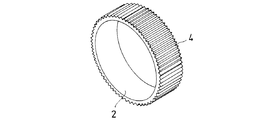
次に、巻芯2について説明する。図2は、本発明の粘着テープ巻回体が備える巻芯の例を示す斜視図である。巻芯2は、円筒状に形成されると共に、その外周面に凹凸形状が連続して形成されている。図2の例では、巻芯2の軸方向に平行に延びる細溝4が、外周面に連続して形成されている。これにより、上述したような比較的低弾性で基材の厚みが薄い粘着テープ3を巻回する際、その巻き始めにおいて、細溝4が粘着テープ3の局所的な伸縮を適度に許容することで、巻き取り皺の発生を防止することができる。
Next, the
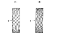
巻芯2の外周面に形成される凹凸形状は、図2に示すような平目状(ストレートパターン)に限られず、粘着テープ3の局所的な伸縮を適度に許容することができるものであれば、他の凹凸形状であってもよい。他の凹凸形状として、例えば、図3(a)に示すような四角目(クロスパターン)や、図3(b)に示すような菱形目(ダイヤモンドパターン)などが挙げられる。凹凸形状を有する巻芯の成形方法としては、特に限定されないが、素材の種類や巻芯の形状などに応じて、射出成形やローレット加工などの公知または慣用の成形方法を適宜利用することができる。
The uneven shape formed on the outer peripheral surface of the
ここで、凹凸形状は、巻芯2の周方向に0.1〜5.0mmのピッチで形成されたものが好ましい。当該ピッチが0.1mm未満であると、上述の粘着テープ3の局所的な伸縮を許容する効果が乏しく、巻き取り皺が発生する場合があるため好ましくない。一方、当該ピッチが5.0mmを超えると、その細溝4において粘着テープ3が弛み易くなるので好ましくない。また、凹凸形状の高低差は、0.5〜2.0mmであるものが好ましい。当該高低差が0.5mm未満であると、上述の粘着テープ3の局所的な伸縮を許容する効果が乏しい場合があるため好ましくない。一方、当該高低差が2.0mmを超えると、その細溝4において粘着テープ3が大きく弛んでしまうので好ましくない。
Here, the concavo-convex shape is preferably formed at a pitch of 0.1 to 5.0 mm in the circumferential direction of the
巻芯2の素材としては、特に限定されないが、合成樹脂からなるものが好ましい。合成樹脂としては、ポリエチレン、ポリプロピレン、エチレン−プロピレン共重合体などのポリオレフィン系樹脂;ポリ塩化ビニル;ポリスチレン、アクリロニトリル−スチレン共重合体(AS樹脂)、アクリロニトリル−ブタジエン−スチレン共重合体(ABS樹脂)などのスチレン系樹脂;ポリエチレンテレフタレート(PET)、ポリブチレンテレフタレート、ポリエチレンナフタレートなどのポリエステル系樹脂;ポリメチルメタクリレート(PMMA)などのメタクリレート系樹脂;ポリアミド;ポリカーボネート(PC);ポリアセタール;ポリイミド;ポリアクリル酸ブチル、ポリアクリル酸エチルなどのポリアクリル酸エステル類;エポキシ系樹脂;ポリウレタン;フェノール樹脂;メラミン樹脂;フッ素樹脂などが挙げられる。合成樹脂は単独で又は2種以上組み合わせて使用することができる。また、合成樹脂には、帯電防止剤や着色剤等の各種添加剤が配合されていてもよい。なお、帯電防止剤を配合することで、粘着テープを巻き戻すときに発生する静電気を抑制することができる。
Although it does not specifically limit as a raw material of the
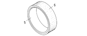
図4は、本発明の別形態に係る巻芯の例を示す斜視図である。図4の巻芯5は、円筒状に形成されると共に、その外周側に弾性体層6が形成されている。これにより、上述したような比較的低弾性で基材の厚みが薄い粘着テープ3を巻回する際、その巻き始めにおいて、弾性体層6が粘着テープ3の局所的な伸縮に適度に追随することで、巻き取り皺の発生を防止することができる。
FIG. 4 is a perspective view showing an example of a winding core according to another embodiment of the present invention. 4 is formed in a cylindrical shape, and an
巻芯5の素材としては、特に限定されないが、上述のように合成樹脂からなるものが好ましい。また、その外周側に形成される弾性体層6は、密度が0.001〜0.1g/cm3の発泡体であるものが好ましく、より好ましい密度は0.03〜0.09g/cm3である。当該密度が0.001g/cm3未満であると、弾性体層6が粘着テープ3の張力により大きく変形して巻回し難くなるため好ましくない。一方、当該密度が0.1g/cm3を超えると、弾性体層6が粘着テープ3の局所的な伸縮に追随する効果が乏しくなるために好ましくない。なお、弾性体層6の厚みは、0.5〜5.0mmであるものが好ましい。当該厚みが0.5mm未満であると、弾性体層6が粘着テープ3の局所的な伸縮に追随する効果が乏しくなるために好ましくない。一方、当該厚みが5.0mmを超えても、巻き取り皺の発生防止の効果はそのままに、粘着テープ3の巻回量が不本意に低減するため好ましくない。
Although it does not specifically limit as a raw material of the
ここで、発泡体としては、ポリエチレンフォームやポリプロピレンフォームなどが用いられる。また、弾性体層6は、粘着テープ3の局所的な伸縮に適度に追随可能な程度に弾性変形するものであれば発泡体に限定されず、例えば、天然ゴムやポリイソプレンゴム、スチレン・ブタジエンゴム、スチレン・イソプレン・スチレンブロック共重合体ゴム、スチレン・ブタジエン・スチレンブロック共重合体ゴム、ブチルゴム、ポリイソブチレン、シリコーンゴム、ニトリルゴム、アクリルゴム、フッ素ゴムなどであってもよい。
Here, a polyethylene foam, a polypropylene foam, etc. are used as a foam. The
巻芯に粘着テープが巻回された粘着テープ巻回体は、一般に、粘着テープ製品の最終形態となる。一方、その粘着テープ巻回体の製造においても、粘着剤などの塗布工程、スリッター切断機による切断工程または巻き替え工程などにおいて、粘着テープの巻き取りが行われ、巻回体の形態となる。本発明に係る粘着テープの製造方法は、図2〜4に例示された巻芯2、5に粘着テープ3を巻回する工程を備えており、図5に例示される。
An adhesive tape wound body in which an adhesive tape is wound around a core is generally the final form of an adhesive tape product. On the other hand, also in the manufacture of the adhesive tape winding body, the adhesive tape is wound up in a coating process such as an adhesive, a cutting process using a slitter cutting machine, or a rewinding process, so that a wound body is formed. The manufacturing method of the adhesive tape which concerns on this invention is equipped with the process of winding the
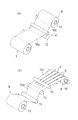
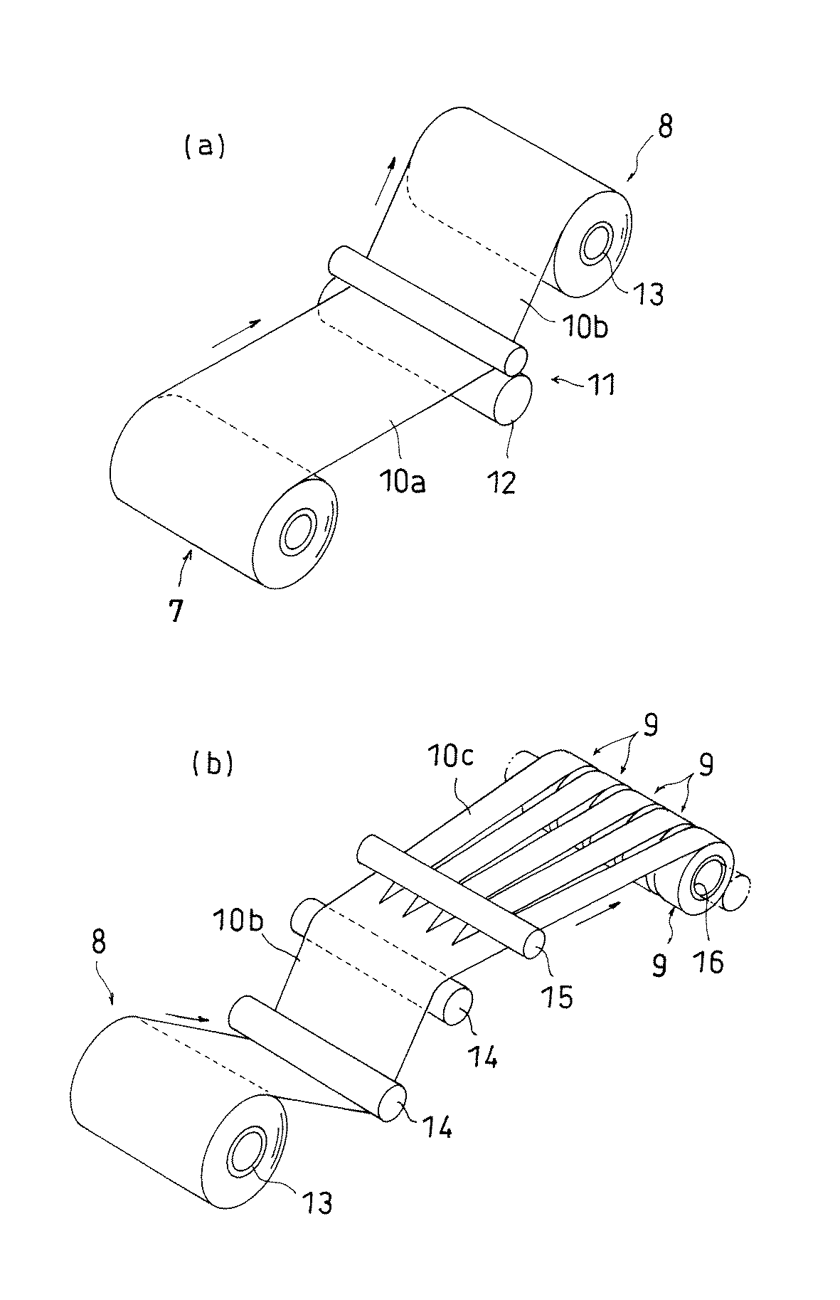
図5は、粘着テープ巻回体の製造工程の一部を説明する概念図であり、図5(a)は粘着剤の塗布工程を、図5(b)はスリッター切断機による切断工程を示している。図5(a)において、粘着剤層形成前のロール状基材7から解かれた基材10aはローラ対11に送られ、ローラ対11が備える塗布ローラ12によって粘着剤が薄く塗布され、粘着剤層が形成される。粘着剤層が形成された基材は、粘着テープ10bとして巻芯13に巻き取られ、粘着テープ巻回体8となる。その後、粘着テープ巻回体8は、図5(b)に示すようなスリッター切断機に送られる。スリッター切断機では、粘着テープ巻回体8から解かれた粘着テープ10bが、ガイドローラ14を介してカッター15に送られ、所定の幅寸法に切断される。切断された粘着テープ10cは、各々巻芯16によって巻き取られ、所定の幅寸法を有する粘着テープ巻回体9となる。
FIG. 5 is a conceptual diagram for explaining a part of the manufacturing process of the adhesive tape roll, FIG. 5 (a) shows an adhesive application process, and FIG. 5 (b) shows a cutting process by a slitter cutter. ing. In FIG. 5A, the
本発明に係る粘着テープの製造方法では、巻芯13または巻芯16に、図2〜4に例示したような巻芯を用いることで、粘着テープ10bまたは粘着テープ10cをそれぞれ巻回する際に、巻き始めの巻き取り皺の発生を防止することができる。特に、図5(a)に示すように、巻回する粘着テープが比較的幅広である場合には、巻き取り皺が発生しやすいために有用である。
In the method for manufacturing the adhesive tape according to the present invention, when the
[他の実施形態]
前述の実施形態では、巻芯2、5が円筒状を呈する例を示したが、本発明では、巻芯2、5が円柱状を呈するものであってもよい。
[Other Embodiments]
In the above-described embodiment, an example in which the
本発明の効果を具体的に示す実施例等について説明する。実施例および比較例の内容を以下に示す。 Examples that specifically show the effects of the present invention will be described. The contents of the examples and comparative examples are shown below.
実施例1
ヤング率が4GPa、且つ、基材の厚みが12μmである500mm幅のPET(#12)の粘着テープを、スリッター切断機にて切断し、巻芯に巻回して粘着テープ巻回体を製造した。巻芯は、内径76mm、外径83mm、幅13mmの円筒状であり、素材はABS樹脂とした。また、巻芯は、その外周面に平目状の凹凸形状が形成されたものを使用した。当該平目状の凹凸は、巻芯を射出成形により成形する際に、その凹凸形状に対応した金型を用いて形成したものであり、周方向ピッチを1.0mm、高低差を1.0mmとした。
Example 1
A 500 mm wide PET (# 12) adhesive tape with a Young's modulus of 4 GPa and a substrate thickness of 12 μm was cut with a slitter cutter and wound around a core to produce an adhesive tape roll. . The winding core was cylindrical with an inner diameter of 76 mm, an outer diameter of 83 mm, and a width of 13 mm, and the material was ABS resin. Further, the core used was one having a flat and uneven shape formed on the outer peripheral surface thereof. The flat irregularities are formed by using a mold corresponding to the irregular shape when the core is formed by injection molding, and the circumferential pitch is 1.0 mm and the height difference is 1.0 mm. did.
実施例2
巻芯の外周面に形成された平目状の凹凸をローレット加工により形成したこと以外は、実施例1と同じとした。
Example 2
Example 1 was the same as Example 1 except that the flat irregularities formed on the outer peripheral surface of the core were formed by knurling.
実施例3
ヤング率が4GPa、且つ、基材の厚みが12μmである500mm幅のPET(#12)の粘着テープを、スリッター切断機にて切断し、巻芯に巻回して粘着テープ巻回体を製造した。巻芯は、内径76mm、外径83mm、幅13mmの円筒状であり、素材はABS樹脂とした。また、巻芯は、その外周側に弾性体層が形成されたものを使用した。当該弾性体層は、密度が0.033g/cm3であるポリオレフィン発泡体(東レ社製トーレペフ(登録商標)HR)を5mmの厚みに貼り付けることで形成した。
Example 3
A 500 mm wide PET (# 12) adhesive tape with a Young's modulus of 4 GPa and a substrate thickness of 12 μm was cut with a slitter cutter and wound around a core to produce an adhesive tape roll. . The winding core was cylindrical with an inner diameter of 76 mm, an outer diameter of 83 mm, and a width of 13 mm, and the material was ABS resin. Further, the core used was one having an elastic layer formed on the outer peripheral side thereof. The elastic layer was formed by sticking a polyolefin foam (Toraypef (registered trademark) HR manufactured by Toray Industries Inc.) having a density of 0.033 g / cm 3 to a thickness of 5 mm.
比較例1
ヤング率が4GPa、且つ、基材の厚みが12μmである500mm幅のPET(#12)の粘着テープを、スリッター切断機にて切断し、巻芯に巻回して粘着テープ巻回体を製造した。巻芯は、内径76mm、外径83mm、幅13mmの円筒状であり、素材はABS樹脂とした。また、巻芯は、その外周面が平滑に形成されたものを使用した。
Comparative Example 1
A 500 mm wide PET (# 12) adhesive tape with a Young's modulus of 4 GPa and a substrate thickness of 12 μm was cut with a slitter cutter and wound around a core to produce an adhesive tape roll. . The winding core was cylindrical with an inner diameter of 76 mm, an outer diameter of 83 mm, and a width of 13 mm, and the material was ABS resin. Further, the core used was one whose outer peripheral surface was formed smoothly.
比較例2
スリッター切断機のカッターと巻芯との間に張力調整機構を設けたこと以外は、比較例1と同じとした。張力調整機構は、ダンサーロールから構成される公知の装置であり、粘着テープの幅方向にわたって一様に一定の設定張力を保持可能に構成されている。
Comparative Example 2
It was the same as Comparative Example 1 except that a tension adjusting mechanism was provided between the cutter and the core of the slitter cutter. The tension adjusting mechanism is a known device composed of dancer rolls, and is configured to be capable of holding a constant set tension uniformly over the width direction of the adhesive tape.
以上の実施例および比較例を用いて、製品歩留まりおよび作業性に対する評価を行った。すなわち、所定数量の粘着テープ巻回体を製造し、その巻き始めに発生した巻き取り皺によって不良品となった個数から良品率を算出し、製品歩留まりを評価した。また、粘着テープの張力を調整したり、変形した粘着テープの修正を行ったりすることで発生した時間ロスを考慮して、作業性を評価した。作業性の評価は三段階とし、○、△、×の順に良好であることを示す。評価結果を表1に示す。 Using the examples and comparative examples described above, the product yield and workability were evaluated. That is, a predetermined number of adhesive tape wound bodies were manufactured, and the yield rate was calculated from the number of defective products due to the winding flaw generated at the beginning of winding, and the product yield was evaluated. Moreover, workability was evaluated in consideration of time loss generated by adjusting the tension of the adhesive tape or correcting the deformed adhesive tape. The workability is evaluated in three stages, and indicates that it is good in the order of ○, Δ, and ×. The evaluation results are shown in Table 1.
一方、実施例1および2では、巻芯の外周面に形成された平目状の凹凸が、粘着テープの局所的な伸縮を適度に許容して、巻き始めの巻き取り皺の発生を防止し、製造した粘着テープ巻回体の全数が良品となった。実施例3においても、巻芯の外周側に形成された発泡体層が、粘着テープの局所的な伸縮に適度に追随して、巻き始めの巻き取り皺の発生を防止し、製造した粘着テープ巻回体の全数が良品となった。また、実施例1〜3では、良品率が100%であることに伴って時間ロスが抑制され、作業性が良好であった。 On the other hand, in Examples 1 and 2, the flat irregularities formed on the outer peripheral surface of the core appropriately allow local expansion and contraction of the adhesive tape, and prevent the occurrence of winding wrinkles at the beginning of winding, All of the manufactured adhesive tape rolls were non-defective. Also in Example 3, the foam layer formed on the outer peripheral side of the core appropriately follows the local expansion and contraction of the pressure-sensitive adhesive tape, and prevents the occurrence of winding wrinkles at the beginning of winding. The total number of rolls became good. Moreover, in Examples 1-3, time loss was suppressed with the non-defective rate being 100%, and workability was good.
1 粘着テープ巻回体
2 巻芯
3 粘着テープ
4 細溝
5 巻芯
6 弾性体層
8 粘着テープ巻回体
9 粘着テープ巻回体
10a 基材
10b 粘着テープ
10c 粘着テープ
12 塗布ローラ
13 巻芯
16 巻芯
DESCRIPTION OF
Claims (6)
Priority Applications (1)
| Application Number | Priority Date | Filing Date | Title |
|---|---|---|---|
| JP2004114003A JP2005298094A (en) | 2004-04-08 | 2004-04-08 | Adhesive tape winding body, winding core used therefor, and method for producing adhesive tape winding body using the winding core |
Applications Claiming Priority (1)
| Application Number | Priority Date | Filing Date | Title |
|---|---|---|---|
| JP2004114003A JP2005298094A (en) | 2004-04-08 | 2004-04-08 | Adhesive tape winding body, winding core used therefor, and method for producing adhesive tape winding body using the winding core |
Publications (1)
| Publication Number | Publication Date |
|---|---|
| JP2005298094A true JP2005298094A (en) | 2005-10-27 |
Family
ID=35330112
Family Applications (1)
| Application Number | Title | Priority Date | Filing Date |
|---|---|---|---|
| JP2004114003A Pending JP2005298094A (en) | 2004-04-08 | 2004-04-08 | Adhesive tape winding body, winding core used therefor, and method for producing adhesive tape winding body using the winding core |
Country Status (1)
| Country | Link |
|---|---|
| JP (1) | JP2005298094A (en) |
Cited By (6)
| Publication number | Priority date | Publication date | Assignee | Title |
|---|---|---|---|---|
| JP5033260B1 (en) * | 2011-12-26 | 2012-09-26 | エーアールシー株式会社 | Label roll body |
| USD668131S1 (en) | 2010-08-27 | 2012-10-02 | Nitto Denko Corporation | Winding core |
| USD668527S1 (en) | 2010-08-27 | 2012-10-09 | Nitto Denko Corporation | Winding core |
| EP2832810A1 (en) | 2013-08-02 | 2015-02-04 | Nitto Denko Corporation | Pressure-sensitive adhesive tape or sheet |
| CN104891273A (en) * | 2015-04-06 | 2015-09-09 | 陈超 | An adhesive tape roll |
| WO2018151145A1 (en) * | 2017-02-15 | 2018-08-23 | リンテック株式会社 | Roll and roll production method |
-
2004
- 2004-04-08 JP JP2004114003A patent/JP2005298094A/en active Pending
Cited By (12)
| Publication number | Priority date | Publication date | Assignee | Title |
|---|---|---|---|---|
| USD668131S1 (en) | 2010-08-27 | 2012-10-02 | Nitto Denko Corporation | Winding core |
| USD668527S1 (en) | 2010-08-27 | 2012-10-09 | Nitto Denko Corporation | Winding core |
| USD683616S1 (en) | 2010-08-27 | 2013-06-04 | Nitto Denko Corporation | Winding core |
| USD683615S1 (en) | 2010-08-27 | 2013-06-04 | Nitto Denko Corporation | Winding core |
| JP5033260B1 (en) * | 2011-12-26 | 2012-09-26 | エーアールシー株式会社 | Label roll body |
| EP2832810A1 (en) | 2013-08-02 | 2015-02-04 | Nitto Denko Corporation | Pressure-sensitive adhesive tape or sheet |
| CN104891273A (en) * | 2015-04-06 | 2015-09-09 | 陈超 | An adhesive tape roll |
| WO2018151145A1 (en) * | 2017-02-15 | 2018-08-23 | リンテック株式会社 | Roll and roll production method |
| CN110325609A (en) * | 2017-02-15 | 2019-10-11 | 琳得科株式会社 | The manufacturing method of roller and roller |
| JPWO2018151145A1 (en) * | 2017-02-15 | 2019-12-12 | リンテック株式会社 | Roll and roll manufacturing method |
| CN110325609B (en) * | 2017-02-15 | 2021-08-17 | 琳得科株式会社 | Roll and roll manufacturing method |
| US11220091B2 (en) | 2017-02-15 | 2022-01-11 | Lintec Corporation | Roll and method for producing roll |
Similar Documents
| Publication | Publication Date | Title |
|---|---|---|
| WO2007148593A1 (en) | Reel | |
| EP2684829A1 (en) | Film winding core, and wound film body using same | |
| EP1384575B1 (en) | Laminate sheet and producing methods therefor | |
| JP2011251797A (en) | Take-up roll | |
| US20160107858A1 (en) | Sheet winding structure | |
| WO2018221285A1 (en) | Web fixing method, web winding method, and winding roll body | |
| JP2002068540A (en) | Winding member | |
| JP2005298094A (en) | Adhesive tape winding body, winding core used therefor, and method for producing adhesive tape winding body using the winding core | |
| JP5632154B2 (en) | Winding core | |
| JPH03243570A (en) | Semirigid hollow cylindrical core and adhesive tape roll and their manufacture | |
| JP2002265889A (en) | Support for adhesive tape and adhesive tape | |
| JPH0673140U (en) | Roll adhesive tape | |
| JP5292234B2 (en) | Narrow web winding method and rolled product | |
| JPH05310346A (en) | Film winding method, winding device, and winding product obtained thereby | |
| JP2008156041A (en) | Pancake for film transfer tool | |
| JP5584635B2 (en) | Sheet, roll sheet and winding method | |
| JP5398137B2 (en) | Winding core for winding sheet | |
| JP6377224B1 (en) | Double-sided adhesive tape for fixing web material and adhesive tape with double-sided separator | |
| TWI877441B (en) | Take-up roll and optical film roll wound on the take-up roll | |
| JP2015006934A (en) | Winding core for film winding and method for manufacturing the same | |
| JP2008260601A (en) | Winding body, manufacturing method thereof, and laminated sheet containing long sheet | |
| JP2002173649A (en) | Wound tape | |
| KR20220114928A (en) | Method for manufacturing roll type adhesive film | |
| JP5202273B2 (en) | Adhesive tape roll | |
| KR101940835B1 (en) | Film sheet winding method using winding roll |
Legal Events
| Date | Code | Title | Description |
|---|---|---|---|
| A621 | Written request for application examination |
Free format text: JAPANESE INTERMEDIATE CODE: A621 Effective date: 20050921 |
|
| A977 | Report on retrieval |
Free format text: JAPANESE INTERMEDIATE CODE: A971007 Effective date: 20071114 |
|
| A131 | Notification of reasons for refusal |
Free format text: JAPANESE INTERMEDIATE CODE: A131 Effective date: 20071120 |
|
| A521 | Written amendment |
Effective date: 20080117 Free format text: JAPANESE INTERMEDIATE CODE: A523 |
|
| RD03 | Notification of appointment of power of attorney |
Effective date: 20080117 Free format text: JAPANESE INTERMEDIATE CODE: A7423 |
|
| A131 | Notification of reasons for refusal |
Free format text: JAPANESE INTERMEDIATE CODE: A131 Effective date: 20080624 |
|
| A521 | Written amendment |
Free format text: JAPANESE INTERMEDIATE CODE: A523 Effective date: 20080818 |
|
| A02 | Decision of refusal |
Effective date: 20090123 Free format text: JAPANESE INTERMEDIATE CODE: A02 |