JP5584635B2 - Sheet, roll sheet and winding method - Google Patents
Sheet, roll sheet and winding method Download PDFInfo
- Publication number
- JP5584635B2 JP5584635B2 JP2011016027A JP2011016027A JP5584635B2 JP 5584635 B2 JP5584635 B2 JP 5584635B2 JP 2011016027 A JP2011016027 A JP 2011016027A JP 2011016027 A JP2011016027 A JP 2011016027A JP 5584635 B2 JP5584635 B2 JP 5584635B2
- Authority
- JP
- Japan
- Prior art keywords
- sheet
- core
- winding
- end portion
- longitudinal direction
- Prior art date
- Legal status (The legal status is an assumption and is not a legal conclusion. Google has not performed a legal analysis and makes no representation as to the accuracy of the status listed.)
- Active
Links
Images

Landscapes
- Winding Of Webs (AREA)
- Storage Of Web-Like Or Filamentary Materials (AREA)
Description
本発明は、シート、ロール状シート及び巻付方法に関する。 The present invention relates to a sheet, a roll sheet, and a winding method.
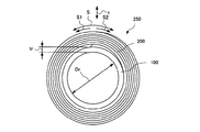
一般に、合成樹脂等を薄い膜状に成型したシートは、図5に示すように、シート200の長手方向Sの端部から円筒状の巻芯100に渦巻き状に巻かれて、ロール状シート250とされる。そして、シート200は、ロール状シート250の状態で、保存、流通に供される。
ここで、シート200が巻芯100に渦巻き状に巻かれると、巻き付け圧力がシート200の厚さ方向tに作用する。
In general, a sheet obtained by molding a synthetic resin or the like into a thin film is spirally wound around the
Here, when the
また、図6に示すように、シート200が巻芯100に巻き付けられる巻き付け始めの側のシート端の側面211と、巻芯側であるシート200の裏側の表面202との間のなす角度θは、略直角である。換言すると、シート200が巻芯100に巻かれた状態において、シート200の端部の側面211は、巻芯100の表面110に対して略直角に形成されている。
Further, as shown in FIG. 6, the angle θ formed between the sheet
そして、シート200が巻芯100に巻かれると、シート200の端部の側面211において、巻芯100の表面110とシート200の表側の表面204との間にシート200の厚さTに相当する高さの段差が形成される。形成された段差の上にシート200が何周も巻かれると、巻かれたシート200の巻き付け圧力により、2周目以降の、形成された前記段差近傍のシート200のうち点線200aで示した範囲に芯部跡と呼ばれるうねりが発生しやすい。
When the
平滑性が要求される用途にシートを使用する場合等は、シート200のうち芯部跡が発生しているところ(例えば、点線200aで示した範囲)を含む部分は、シートとしての商品価値がないために不良品となる場合がある。このため、芯部跡により不良品となる部分に応じた長さのシートを補填するために、芯部跡が発生する長さ(端部の側面211から芯部跡が発生しない位置までのシート200の長さ)を想定し、想定した長さ(例えば30m)を余分に長く巻芯100に巻いたロール状シート250をシート利用者に提供する必要があり、シートの製造時間が長時間化したり、余計なシートの材料費が必要になりシートが高価格化したりする問題がある。
When a sheet is used for an application where smoothness is required, the portion of the
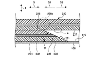
芯部跡の発生を抑える技術として特許文献1に記載の技術が知られている。図7に示すように、特許文献1に開示されているシート230は、巻芯100の表面110と、シート230の長手方向Sにおける巻き付け始めの端部の側面231との間のなす角度θが鋭角とされている。このため、巻芯100の表面110とシート230の表側の表面235との間に形成される段差がゆるやかになり、特許文献1に記載の技術は、シート230の長手方向Sの端部の側面231における2周目以降のシート230の部分230aに発生する芯部跡を抑えることができる。
A technique described in
しかしながら、図7に示すように、端部の側面231がシート230を刃物等で切断して形成されている場合、側面231の切断面は平滑でないことが多い。1周目のシート230に重ねて巻き取られる2周目のシート230の裏側の表面237が、巻き付け圧力により、そのような側面231に押圧されると、2周目の裏側の表面237に側面231の切断面の跡が生じるおそれがある。
However, as shown in FIG. 7, when the
また、特許文献1に記載の技術を、粘着剤層を含む複数の層からなるシート230に適用すると、次の問題が生じる。例えば、複数の層からなるシート230は、基材シート232と、基材シート232の裏面234に一様に粘着剤が塗布されて形成された粘着剤層236と、その粘着剤層236の全面を覆う剥離シート238とを備える。
Further, when the technique described in
このような複数の層からなるシート230の端部の側面231の面はシート230の厚さ方向tにおいて巻芯100とは反対の方向に向いている。このため、端部の側面231に露出している粘着剤層236の粘着剤が巻き付け圧力によって端部の側面231からはみ出て、はみ出た粘着剤が2周目のシート230の剥離シート238の例えば点線で示す範囲aに付着してしまうおそれがある。
The surface of the
そして、はみ出た粘着剤が2周目のシート230の剥離シート238に付着すると、端部の側面231と2周目のシート230の剥離シート238とが、互いに密着し、剥がれなくなるブロッキングと呼ばれる現象が発生しやすい。
特に、ジャンボロール製品群と呼ばれる幅及び巻き取り長さが長いサイズのシートは、巻き付け圧力が大きくなるので、ブロッキングが発生する可能性はより高くなる。
Then, when the protruding adhesive adheres to the
In particular, a sheet having a long width and winding length called a jumbo roll product group has a high winding pressure, and thus has a higher possibility of blocking.
本発明は、芯部跡やブロッキングが発生しにくいシート、ロール状シート及び巻付方法を提供することを目的とする。 An object of this invention is to provide the sheet | seat, roll-shaped sheet | seat, and winding method which a core part trace and blocking hardly generate | occur | produce.
本発明に係るシートは、巻芯に巻き付けられるシートであって、前記シートの巻き付け始めの長手方向のシート端の、前記シートの厚さ方向の切断面において、前記巻芯側となる裏側の表面の先端部が、前記巻芯側とは反対側にあたる表側の表面の先端部よりも、前記シートの長手方向のうち、シートを巻き付ける巻き付け方向の側にあることを特徴とする。
本発明のシートによれば、巻芯側となる裏側の表面の先端部が、巻芯側と反対側にあたる表側の表面の先端部よりも巻き付け方向の側にあるので、シートが巻芯に巻かれた際に、シート端の側面と巻芯の表面との間に、シート端が巻芯側に撓むための空間が形成される。シート端は、シート端に巻かれた2周目以降のシートによる巻き付け圧力により、この空間内で巻芯側に撓み、巻芯の表面からシートにおいて裏側の表面とは反対側にあたる表側の表面への緩やかな傾斜面を形成する。このため、シート端の近傍に巻かれたシートの部分に、芯部跡が付きにくくすることができる。
The sheet according to the present invention is a sheet that is wound around a core, and is a surface on the back side that is the core side in the cut surface in the thickness direction of the sheet at the sheet end in the longitudinal direction at the start of winding of the sheet The front end portion of the sheet is on the side in the winding direction in which the sheet is wound, in the longitudinal direction of the sheet, with respect to the front end portion of the surface on the opposite side to the core side.
According to the sheet of the present invention, the front end portion of the back surface that is the core side is on the side in the winding direction with respect to the front end portion of the front surface that is opposite to the core side, so the sheet is wound around the core. When this occurs, a space is formed between the side surface of the sheet end and the surface of the core to allow the sheet end to bend toward the core. The sheet end bends to the core side in this space due to the winding pressure of the second and subsequent sheets wound around the sheet end, and from the surface of the core to the surface on the opposite side of the sheet from the back surface A gently sloping surface is formed. For this reason, it is possible to make it difficult for the core mark to be attached to the portion of the sheet wound in the vicinity of the sheet end.
本発明に係るシートは、基材シート、粘着剤層及び剥離シートが順次積層されていてもよい。上述のように、巻芯側となる裏側の表面の先端部が、巻芯側と反対側にあたる表側の表面の先端部よりも、シートの長手方向のうち、巻き付ける方向の側にあるので、シートが巻芯に巻かれた際に、シート端の側面と巻芯の表面との間に、シート端が巻芯側に撓むための空間が形成される。そして、シートは、さらに、基材シート、粘着剤層及び剥離シートが順次積層されているので、シート端の側面において、粘着剤層は巻芯側に向いており、かつ、その表側の表面の先端部と粘着剤層との間に基材シートが露出している。このため、シートが巻芯に巻かれたときに、シート端の側面からはみ出た粘着剤は、2周目のシートの剥離シート材に付着しにくくなるので、はみ出た粘着剤が2周目のシートの剥離シート材に付着することにより生じるブロッキングの発生を抑えることができる。 In the sheet according to the present invention, a base sheet, an adhesive layer and a release sheet may be sequentially laminated. As described above, the front end of the surface on the back side that is the core side is closer to the winding direction in the longitudinal direction of the sheet than the front end of the front surface that is opposite to the core side. Is wound around the core, a space is formed between the side surface of the sheet end and the surface of the core to allow the sheet end to bend toward the core. And since the sheet | seat is further laminated | stacked in order by the base material sheet, the adhesive layer, and the peeling sheet, in the side surface of a sheet | seat end, the adhesive layer is suitable for the core side, and the surface of the surface side is the surface side. The base material sheet is exposed between the tip portion and the pressure-sensitive adhesive layer. For this reason, when the sheet is wound around the core, the adhesive that protrudes from the side surface of the sheet end is less likely to adhere to the release sheet material of the second round sheet, so Generation | occurrence | production of the blocking produced by adhering to the peeling sheet material of a sheet | seat can be suppressed.
前記シートの長手方向の前記シート端の側面と前記裏側の表面との間のなす角度は、95°以上175°以下の範囲内にあることが好ましく、100°以上170°未満の範囲内にあることがより好ましく、115°以上165°未満の範囲にあることがさらに好ましい。前記角度が95°未満又は175°以上になると、シート端が巻芯側に十分に撓むことができないので、前記のような効果を十分に得ることができない。 The angle formed between the side surface of the sheet end in the longitudinal direction of the sheet and the surface on the back side is preferably in the range of 95 ° or more and 175 ° or less, and in the range of 100 ° or more and less than 170 °. It is more preferable that it is in the range of 115 ° or more and less than 165 °. When the angle is less than 95 ° or 175 ° or more, the sheet end cannot be sufficiently bent toward the core, and thus the above-described effects cannot be sufficiently obtained.
本発明に係るロール状シートは、前記いずれかに記載のシートと、前記シートが巻き付けられる巻芯と、を備える。本発明のロール状シートによれば、芯部跡がシートに発生しにくくすることができる。 A roll-shaped sheet according to the present invention includes any one of the above-described sheets and a core around which the sheet is wound. According to the roll-shaped sheet of the present invention, it is possible to make it difficult for the core mark to be generated on the sheet.
本発明に係る巻付方法は、上述のシートを前記巻芯に巻き付ける巻付方法であって、前記シート端の側面が前記巻芯側に向くように、前記シート端を前記巻芯に巻き付ける。本発明の巻付方法によれば、巻付方法によって巻かれたシートには、芯部跡が発生しにくい。 The winding method according to the present invention is a winding method in which the above-described sheet is wound around the core, and the sheet end is wound around the core such that a side surface of the sheet end faces the core. According to the winding method of the present invention, a core mark is unlikely to occur on a sheet wound by the winding method.
本発明によれば、芯部跡やブロッキングが発生しにくいシート、ロール状シート及び巻付方法を提供することができる。 ADVANTAGE OF THE INVENTION According to this invention, the sheet | seat, roll-shaped sheet | seat, and winding method which a core part trace and blocking cannot generate | occur | produce can be provided.
以下に、本発明の実施形態を図面に基づいて詳細に説明する。なお、この実施形態により本発明が限定されるものではない。 Embodiments of the present invention will be described below in detail with reference to the drawings. In addition, this invention is not limited by this embodiment.
〔第1実施形態〕
図1及び図2を参照して、本発明に係るシート10及びロール状シート150の第1実施形態について説明する。
[First Embodiment]
With reference to FIG.1 and FIG.2, 1st Embodiment of the sheet |
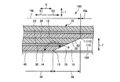
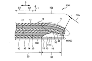
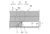
図1は、シート10を巻芯100に巻いたロール状シート150の部分拡大断面図である。図2は、図1に示したロール状シート150において巻き付け圧力が作用した状態を示す部分拡大断面図である。ここで、図1及び図2に示すシート10は、シート10の厚さ方向tに重なった状態となっている。
FIG. 1 is a partially enlarged cross-sectional view of a
図1に示すように、シート10は、基材シート20と、基材シート20の一方の面22に積層された粘着剤層30と、粘着剤層30に積層された剥離シート40とを備える。基材シート20の材質としては、合成樹脂が好ましい。
As shown in FIG. 1, the
シート10は、基材シート20において基材シート20の一方の面22と反対側にあたる面である表側の表面12と、シート10において表側の表面12とは反対側にあたる裏側の表面14とを有する。
シート10は、シート10の幅方向と直角の長手方向Sにおいて、一方のシート端11と他方のシート端(図示せず)とを有する。シート10は、長手方向Sにおいて、一方のシート端11から他方のシート端(図示せず)に向けて順に巻芯100に巻き付けられる(このときの一方のシート端11から他方のシート端(図示せず)への方向を巻き付け方向S1という。)。シート10は、裏側の表面14が在る範囲のシート本体部50と、シート10の長手方向Sのシート本体部50よりシート端11の側の範囲のシート端部60とを有する。
The
The
シート端部60は、シート10の表側の表面12の先端部13と、シート10の裏側の表面14の先端部15とをつなぐ側面62を有する。シート端部60の側面62は、シート端11の側面でもある。ここで、シート10の巻き付け始めの長手方向Sのシート端11の、シート10の厚さ方向tの切断面において、シート10の裏側の表面14の先端部15は、シート10の表側の表面12の先端部13よりも、シート10の長手方向Sのうち、巻き付け方向S1の側(シート10の長手方向Sにおいて、一方のシート端11より他方のシート端(図示せず)の側)にある。
The
シート端部60の側面62と、裏側の表面14を長手方向Sにおいて巻き付け方向S1とは反対方向S2に延長した仮想平面16との間には、シート10の厚さ方向tにおいて、シート端部60の側面62と仮想平面16との間の寸法がシート10の裏側の表面14の先端部15から表側の表面12の先端部13に向かうに従って大きくなる空間70が形成されている。
Between the
つまり、シート本体部50は裏側の表面14を備えている範囲であるので、シート10が巻芯100に巻かれた状態においてシート本体部50はシート10の厚さ方向tにおいて巻芯100側に撓まない。これに対して、シート端部60は、シート端部60の側面62と仮想平面16との間に空間70があるので、シート10が巻芯100に巻かれた状態においてシート端部60は、空間70が減少するように、シート10の厚さ方向tにおける巻芯100側に撓む(図2参照)。
That is, since the sheet
なお、図1においては、表側の表面12の先端部13とシート10の長手方向Sにおけるシート端11とは一致している。
In FIG. 1, the
シート端部60の側面62は、図1においては、平面として説明しているが、表側の表面12側に凸の曲面や、仮想平面16側に凸の曲面や、これらの組み合わせであってもよい。
シート端部60の側面62は、例えば、シート10をカッターのような切断装置により切断して形成される。
The
The
また、シート端部60は、長手方向Sにおいて、シート10の裏側の表面14の先端部15から表側の表面12の先端部13に向かってシート10の断面積が小さくなる形状を有する。
Further, the
シート10の裏側の表面14の先端部15を挟んで、シート端部60の側面62と裏側の表面14との間のなす角度θは、95°以上175°以下の範囲内、好ましくは、100°以上170°未満の範囲内にあり、より好ましくは、115°以上165°未満の範囲である。
The angle θ formed between the
巻芯100の側に向いているシート端部60の側面62には、表側の表面12の先端部13から裏側の表面14の先端部15に向けて、順に、基材シート20と粘着剤層30と剥離シート40とのそれぞれの切断面が露出している。したがって、シート端部60の側面62に露出している粘着剤層30と表側の表面12の先端部13との間には、巻芯100の側に向くように傾斜している基材シート20の露出面32がある。
On the
図1及び図2に示すように、ロール状シート150は、上述のシート10と、シート10が長手方向Sに巻き付けられる巻芯100とを備える。
As shown in FIGS. 1 and 2, the roll-shaped
本発明で用いる基材シート20としては特に制限はなく、様々なものを用いることができる。基材シートの具体例としては、ポリエチレン、ポリプロピレン等のポリオレフィン、ポリエチレンテレフタレート、ポリエチレンナフタレート、ポリブチレンテレフタレート等のポリエステル、ポリイミド、ポリアミド、ポリアセテート、ABS、ポリスチレン、塩化ビニル等の樹脂からなるシート及びこれらの樹脂の混合物又は積層物からなるシート、これらのシートにアルミニウム等の金属蒸着を施したもの等があげられる。これらプラスチックの基材シートは、未延伸でもよいし、縦又は横等の一軸方向若しくは二軸方向に延伸されていてもよい。
さらには、基材シートとしては、上質紙、含浸紙、アート紙、コート紙、グラシン紙等からなる紙類、これらの紙基材にポリエチレン等の熱可塑性樹脂をラミネートしたラミネート紙等の各種紙類、アルミニウム箔や銅箔や鉄箔等の金属箔、さらには不織布、合成紙等が用いられる。
これらの基材シートの厚さは、特に制限はなく、通常2μm〜1000μm程度の範囲であるが、取り扱いやすさの面から、好ましくは10μm〜500μm程度の範囲である。
There is no restriction | limiting in particular as the
Furthermore, as the base sheet, various types of paper such as high-quality paper, impregnated paper, art paper, coated paper, glassine paper, and laminated paper obtained by laminating a thermoplastic resin such as polyethylene on these paper base materials. Metal foils such as aluminum foil, copper foil, and iron foil, nonwoven fabric, and synthetic paper are used.
The thickness of these substrate sheets is not particularly limited, and is usually in the range of about 2 μm to 1000 μm, but is preferably in the range of about 10 μm to 500 μm from the viewpoint of ease of handling.
粘着剤層30に用いられる粘着剤としては、例えば、天然ゴム系粘着剤、合成ゴム系粘着剤、アクリル樹脂系粘着剤、ポリエステル樹脂系粘着剤、ポリビニルエーテル樹脂系粘着剤、ウレタン樹脂系粘着剤、シリコーン樹脂系粘着剤等が挙げられる。
合成ゴム系粘着剤の具体例としては、スチレン−ブタジエンゴム、ポリイソブチレンゴム、イソブチレン−イソプレンゴム、イソプレンゴム、スチレン−イソプレンブロック共重合体、スチレン−ブタジエンブロック共重合体、スチレン−エチレン−ブチレンブロック共重合体、エチレン−酢酸ビニル熱可塑性エラストマー等が挙げられる。アクリル樹脂系粘着剤の具体例としては、アクリル酸、アクリル酸メチル、アクリル酸エチル、アクリル酸プロピル、アクリル酸ブチル、アクリル酸−2−エチルヘキシル、メタクリル酸メチル、メタクリル酸エチル、メタクリル酸ブチル、アクリロニトリル等の単独重合体若しくは共重合体等が挙げられる。ポリエステル樹脂系粘着剤は、多価アルコールと多塩基酸の共重合体であり、多価アルコールとしてはエチレングリコール、プロピレングリコール、ブタンジオール等が挙げられ、多塩基酸としては、テレフタル酸、アジピン酸、マレイン酸等が挙げられる。ポリビニルエーテル樹脂系粘着剤の具体例としては、ポリビニルエーテル、ポリビニルイソブチルエーテル等が挙げられる。シリコーン樹脂系粘着剤の具体例としては、ジメチルポリシロキサン等が挙げられる。これらの粘着剤は、1種単独で又は2種以上を組み合わせて用いることができる。
Examples of the pressure-sensitive adhesive used for the pressure-
Specific examples of the synthetic rubber pressure-sensitive adhesive include styrene-butadiene rubber, polyisobutylene rubber, isobutylene-isoprene rubber, isoprene rubber, styrene-isoprene block copolymer, styrene-butadiene block copolymer, styrene-ethylene-butylene block. A copolymer, ethylene-vinyl acetate thermoplastic elastomer, etc. are mentioned. Specific examples of the acrylic resin-based adhesive include acrylic acid, methyl acrylate, ethyl acrylate, propyl acrylate, butyl acrylate, 2-ethylhexyl acrylate, methyl methacrylate, ethyl methacrylate, butyl methacrylate, acrylonitrile Homopolymers or copolymers such as The polyester resin-based pressure-sensitive adhesive is a copolymer of polyhydric alcohol and polybasic acid. Examples of the polyhydric alcohol include ethylene glycol, propylene glycol, and butanediol. Polybasic acids include terephthalic acid and adipic acid. And maleic acid. Specific examples of the polyvinyl ether resin-based pressure-sensitive adhesive include polyvinyl ether and polyvinyl isobutyl ether. Specific examples of the silicone resin pressure-sensitive adhesive include dimethylpolysiloxane. These pressure-sensitive adhesives can be used alone or in combination of two or more.
また、前記粘着剤層には、必要に応じて粘着付与剤、軟化剤、老化防止剤、填料、染料又は顔料等の着色剤等を配合することができる。粘着付与剤としては、ロジン系樹脂、テルペンフェノール樹脂、テルペン樹脂、芳香族炭化水素変性テルペン樹脂、石油樹脂、クマロン・インデン樹脂、スチレン系樹脂、フェノール系樹脂、キシレン樹脂等が挙げられる。軟化剤としては、プロセスオイル、液状ゴム、可塑剤等が挙げられる。填料としては、シリカ、タルク、クレー、炭酸カルシウム等が挙げられる。
粘着剤層の厚さは、特に制限ないが、通常1μm〜200μmであればよく、好ましくは3μm〜100μmである。
なお、本発明における粘着剤層30とは、シート状の中間基材の両側に粘着剤を積層した両面テープタイプのものも含む。中間基材としては、基材シート20として前述したものの中から選択でき、中間基材の両側に積層する粘着剤としては、前記で例示した粘着剤を使用することができる。
The pressure-sensitive adhesive layer may contain a tackifier, a softening agent, an anti-aging agent, a filler, a colorant such as a dye or a pigment, and the like as necessary. Examples of the tackifier include rosin resins, terpene phenol resins, terpene resins, aromatic hydrocarbon-modified terpene resins, petroleum resins, coumarone / indene resins, styrene resins, phenol resins, xylene resins, and the like. Examples of the softener include process oil, liquid rubber, and plasticizer. Examples of the filler include silica, talc, clay, calcium carbonate and the like.
The thickness of the pressure-sensitive adhesive layer is not particularly limited, but is usually 1 μm to 200 μm, preferably 3 μm to 100 μm.
In addition, the
本発明の剥離シート40としては、例えばグラシン紙、コート紙、上質紙等の紙基材、これらの紙基材にポリエチレンやポリプロピレン等の熱可塑性樹脂をラミネートしたラミネート紙、また前記基材にセルロース、デンプン、ポリビニルアルコール、アクリル−スチレン樹脂等で目止め処理を行なった紙基材、あるいはポリエチレンテレフタレート、ポリブチレンテレフタレート、ポリエチレンナフタレート等のポリエステルフィルム、ポリエチレンやポリプロピレン等のポリオレフィンフィルムのようなプラスチックフィルム、及びこれらのプラスチックフィルムに易接着処理を施したフィルム等に剥離剤を塗布し、剥離剤層を形成させたもの等が挙げられる。
剥離剤層を形成させるために用いる剥離剤としては、例えばオレフィン系樹脂、イソプレン系樹脂、ブタジエン系樹脂等のゴム系エラストマー、長鎖アルキル系樹脂、アルキド系樹脂、フッ素系樹脂、シリコーン系樹脂等が用いられる。
Examples of the
Examples of the release agent used to form the release agent layer include rubber elastomers such as olefin resins, isoprene resins, butadiene resins, long chain alkyl resins, alkyd resins, fluorine resins, silicone resins, etc. Is used.
巻芯100としては、その材質は特に限定されるものではなく、例えば、紙の積層重合体のほか、ポリ塩化ビニル、ポリエチレン、ポリプロピレン、ポリスチレン、アクリロニトリル−ブタジエン−スチレン共重合体(ABS)等の熱可塑性樹脂、フェノール樹脂類、エポキシ等の熱硬化性樹脂、及び熱可塑性樹脂又は熱硬化性樹脂を繊維で強化したFRP等が使用可能である。
巻芯100に巻かれるシート10の長さ寸法は、例えば、1m〜5万mとされ、好ましくは30m〜3万mとされ、より好ましくは100m〜1万mとされる。幅寸法は、例えば、10mm〜1万mmとされ、好ましくは50mm〜5000mmとされ、より好ましくは100mm〜3000mmとされる。厚さ寸法は、例えば、5μm〜5000μmとされ、好ましくは50μm〜1000μmとされ、より好ましくは100μm〜500μmとされる。
巻芯100は、通常円筒の外形を有する。巻芯100は、シート10の幅寸法と略同じかそれ以上の幅寸法を有する。巻芯100の内径Dr(図5参照)は、例えば、5mm〜3mとされ、好ましくは1cm〜1mとされ、より好ましくは3cm〜50cmとされる。
巻芯100の円筒を形成する素材の厚さtr(図5参照)は特に限定されないが、例えば1mm〜10cmとされ、好ましくは5mm〜5cmとされる。
The material of the
The length dimension of the
The
Although the thickness tr (refer FIG. 5) of the raw material which forms the cylinder of the
以上のシート10は巻芯100に以下のように巻かれる。なお、シート10を巻芯100に巻き取る時は、シート10の巻き付け方向S1の所定の張力をシート10に付与させた状態で行うことが好ましい。
The
シート10は、シート端部60の側面62が巻芯100の表面110に向くように、かつ、長手方向Sと巻芯100に巻き付けられる巻き付け方向S1とが同一となるように、裏側の表面14を巻芯100側に向けて、巻芯100に巻かれる。
The
シート10を巻芯100に巻き付けるときは、まず、シート10のシート端11を巻芯100の表面110に直接巻き付けるか、又は巻き付け始めの部位であるシート10の長手方向Sのシート端11の近傍のシート10の裏側の表面14に粘着剤層を形成して、巻芯100の表面110に巻き付ける。
When the
(シート10を巻芯100に1周巻いた状態)
シート10を巻芯100に巻き付けると、シート本体部50は、巻芯100の表面110に1周分直接巻かれる(ここで、巻芯100の表面110に巻かれた1周分のシート本体部50を1周目の部分10aとする。)。
(A state where the
When the
シート10のシート本体部50が巻芯100に巻かれると、裏側の表面14の先端部15の近傍において、裏側の表面14を長手方向Sにおいて巻き付け方向S1とは反対方向S2に延長した仮想平面16は、巻芯100の表面110と略一致する。このため、シート10は、シート端部60の側面62と巻芯100の表面110との間に空間70が形成されるように、巻芯100に巻かれる。
When the sheet
シート本体部50は、巻芯100に巻かれているので、梁構造でいう固定端として作用する。また、シート端部60の巻芯100側には空間70が形成されているので、シート端部60はシート10の長手方向Sにおいて巻き付け方向S1とは反対方向S2のシート端11を自由端とする片持ち梁の構造を構成する。
Since the sheet
(シート10を巻芯100に2周巻いた状態)
さらに、2周目のシート10をシート端部60及び1周目の部分10aの表側の表面12に巻き付けると、2周目のシート10は、1周目の部分10aの表側の表面12にさらに1周分巻かれる(ここで、さらに1周分巻かれたシート本体部50の部分を2周目の部分10bとする。)。
(A state where the
Further, when the
図2に示すように、シート端部60における表側の表面12に2周目の部分10bが巻かれると、表側の表面12の先端部13は、シート端部60の弾性変形により、空間70内において巻芯100側に撓む。
As shown in FIG. 2, when the second
撓んだシート端部60における表側の表面12は、巻芯100とは反対側に出っ張る凸の曲面となる。この曲面は、繋ぎ目や段差のない緩やかな面となる。また、表側の表面12は、シート本体部50から撓んだシート端部60に亘って繋ぎ目や段差のない緩やかな凸の曲面を形成する。
The
その結果、シート端部60は巻芯100の表面110側に撓むので、巻芯100の表面110から離れたシート10が1周目の部分10aのシート本体部50の表側の表面12に巻かれるまでの部分bに段差が生じにくくなる。
As a result, the
シート端部60の側面62がシート10の切断により形成されている等により、シート端部60の側面62の表面粗さが表側の表面12の表面粗さと異なっていても、シート端部60の側面62は、巻芯100の表面110側に向いており、2周面の部分10bの裏側の表面14側に向いていないので、シート端部60の側面62が裏側の表面14に接触することがない。このため、2周目以降の裏側の表面14にシート端部60の側面62の切断面の粗さによる跡が形成されることがない。
Even if the surface roughness of the
シート端部60の側面62が巻芯100の表面110側に向いており、かつ、シート端部60の側面62には、シート10の長手方向Sにおけるシート端11(表側の表面12の先端部13でもある)と粘着剤層30との間に基材シート20の切断面が露出している露出面32がある。このため、シート10が巻芯100に巻かれたときに、粘着剤層30の粘着剤がシート端部60の側面62からはみ出ても、はみ出た粘着剤の位置と2周目の部分10bの剥離シート40との間に距離があるので、はみ出た粘着剤は、2周目の部分10bの剥離シート40に到達しにくい。
The
さらに、シート端部60の側面62は、巻芯100の表面110から離れる方向に凹んだ凹曲面を形成するので、シート端部60の側面62からはみ出た粘着剤は、凹曲面を形成するシート端部60の側面62と巻芯100の表面110とにより形成される空間に溜まる。
Further, since the
このため、シート端部60の側面62からはみ出た粘着剤は、露出面32と、凹曲面を形成するシート端部60の側面62と巻芯100の表面110とにより形成される空間とによって、2周目の部分10bの剥離シート40に付着することを防止するので、ブロッキングが発生しにくい。
For this reason, the adhesive protruding from the
〔第2実施形態〕
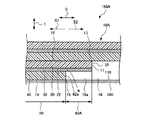
図3を参照して、本発明に係るシート10A及びロール状シート150Aについて説明する。なお、第1実施形態と同一の構成部分については、同一の符号を付して説明を省略する。
[Second Embodiment]
With reference to FIG. 3, the sheet |
図3に示すように、剥離シート40の端部(後述の先端部15)は、剥離シート40に粘着剤層30を介して積層された基材シート20の端部(後述の先端部13)よりも巻き付け方向S1の側にある。また、粘着剤層30は、基材シート20の一方の面22の全体に亘って形成されている。このため、シート10の長手方向Sにおいてシート本体部50よりシート端11の側(巻き付け方向S1とは反対方向S2の側)の範囲であるシート端部60Aは、基材シート20及び粘着剤層30で構成される。粘着剤層30が基材シート20に対して巻芯100側に配置されている。
As shown in FIG. 3, the end of the release sheet 40 (
シート10Aの切断面において、シート10Aの裏側の表面14の先端部15が、シート10Aの表側の表面12の先端部13よりも巻き付け方向S1の側(図3において左側)にある。したがって、剥離シート40の端部の側面62aと、裏側の表面14を長手方向Sに延長した仮想平面16と、粘着剤層30の巻芯100側の表面と、基材シート20の露出面32(切断面)をシート10Aの厚さ方向tに延長した仮想面とによって囲まれた領域には、シート端部60Aが巻芯100側に撓むための空間70aが形成されている。つまり、空間70aは、剥離シート40の端部の側面62aよりもシート10Aの長手方向Sにおいてシート端11の側に形成されている。
また、空間70aは、シート10Aの厚さ方向tにおいて、仮想平面16と、粘着剤層30の巻芯100側の表面との間の寸法が略一定の矩形状とされる。
なお、シート10Aの表側の表面12の先端部13は、シート10Aの幅方向に延びる線状部分である。一方、シート10Aの長手方向Sにおけるシート端11は、基材シート20の端部であるので、シート10Aの幅方向及び厚さ方向tに延びる面状部分である。
In the cut surface of the
The
The
シート10Aが巻芯100に巻かれると、巻かれる際に生じる巻き付け圧力によって、粘着剤層30においてシート本体部50とシート端部60Aとの間の境目bにある粘着剤が、巻き付け方向S1とは反対方向S2に押し出される。しかし、粘着剤が押し出された位置(境目b)と2周目のシート10Aの部分の剥離シート40との間には、長手方向Sにおいてシート端部60Aの長さに相当する距離があり、また、前述の空間70aが形成されているので、はみ出た粘着剤は空間70aに溜まる状態となる。このため、はみ出た粘着剤は、2周目のシート10Aの部分の剥離シート40に到達しにくい。
When the
〔他の実施形態〕
第1実施形態及び第2実施形態では、シートは、基材シート、粘着剤層及び剥離シートを有しているとして説明したが、これに限定されず、基材シートのみで構成されていてもよいし、基材シートと粘着剤層とのみで構成されていてもよい。
Other Embodiment
In 1st Embodiment and 2nd Embodiment, although the sheet | seat demonstrated as having a base material sheet, an adhesive layer, and a peeling sheet, it is not limited to this, Even if comprised only with a base material sheet It may be composed only of the base sheet and the pressure-sensitive adhesive layer.
図1及び図2に示すシート10について、以下の試験1〜3を行い、芯部跡様うねり又は芯部跡及びブロッキングの発生の有無を確認する試験を行った。なお、シート10の作製については後述する。
The following
〔実施例1〜3、比較例1〕
(試験1:裏側の表面とシート端の側面との間のなす角度θの違いによる確認試験)
表1に示す試験条件のシート(実施例1〜3、比較例1)を作製し、万能材料試験機5581(インストロンジャパンカンパニィリミテッド社製)を用いて芯部跡と同じ原理で発生するうねり(芯部跡様うねり)及びブロッキングの発生の有無を確認した。すなわち、図4に示すように、複数のシート330を束ねたシート束320に試験対象のシート340を置き、その上におもり310を置くように構成されている試験装置300を作成した。この試験装置300を用いて荷重をかけることにより、シート340(巻芯に巻かれた1周目のシートに相当)とシート束320(巻芯に巻かれた2周目以降のシートに相当)に巻き付け圧力が作用したのと同じ状態を再現できる。
[Examples 1 to 3, Comparative Example 1]
(Test 1: Confirmation test based on the difference in angle θ between the back surface and the side surface of the sheet end)
Sheets (Examples 1 to 3 and Comparative Example 1) having the test conditions shown in Table 1 are prepared and generated on the same principle as the core trace using a universal material testing machine 5581 (manufactured by Instron Japan Company Limited). The presence or absence of undulation (core trace-like undulation) and blocking was confirmed. That is, as shown in FIG. 4, a
ここで、試験対象のシート340の裏側の表面(おもり310が置かれる面)と長手方向のシート端の側面との間のなす角度θを、表1に示すようにした。
Here, the angle θ formed between the surface on the back side of the

試験条件を以下に示す。
おもり310の荷重:1MPa
荷重負荷時間:おもり310を16時間乗せる。
荷重環境:室温23℃、相対湿度50%
シート330、340:サイズ 100mm×100mm
基材シート:厚さ25μmのポリエチレンテレフタレート(PET)フィルム[三菱化学ポリエステルフィルム株式会社製、商品名「PET25T620EW07」]
粘着剤:アクリル系粘着剤[リンテック株式会社製、商品名「PU−V」]
剥離シート:厚さ38μmの離型ポリエステルフィルム[リンテック株式会社製、商品名「スーパステックSP−PET38(S)」]
シート10の作製:前記基材シートに前記粘着剤を固形分で20g/m2塗布して得られた粘着シートと前記剥離シートを、上下2軸剥離ラミ試験機HDF−905L−800[萩原工業株式会社製]を用いて積層してシート10(総厚83μm)を得た。
シート330の作製:得られたシート10を裁断し100mm×100mmの大きさになるようにシート330を作製した。
シート340の作製:得られたシート10の長手方向におけるシート端11を、角度θが表1の角度になるように切断した後、他の部分を裁断し100mm×100mmの大きさになるようにシート340を作製した。
Test conditions are shown below.
Loading time: The
Load environment: room temperature 23 ° C,
Base sheet: Polyethylene terephthalate (PET) film having a thickness of 25 μm [Mitsubishi Chemical Polyester Film Co., Ltd., trade name “PET25T620EW07”]
Adhesive: Acrylic adhesive [Lintec Co., Ltd., trade name “PU-V”]
Release sheet: release polyester film with a thickness of 38 μm [manufactured by LINTEC Corporation, trade name “Super Tech SP-PET38 (S)”]
Production of Sheet 10: An adhesive sheet obtained by applying 20 g / m 2 of the pressure-sensitive adhesive to the base sheet in solid content and the release sheet were mixed with an upper and lower biaxial peel tester HDF-905L-800 [Ebara Industries The sheet 10 (total thickness 83 μm) was obtained by stacking using “made by Co., Ltd.”.
Production of sheet 330: The obtained
Production of sheet 340: After the
図4に示すように、角度θが表1の角度になるように切断したシートの長手方向Sのシート端の側面がシート束320の最上部のシート330の中央に位置するように、試験対象のシート340(実施例1〜3及び比較例1)を裏側の表面、つまり、剥離シートが上になるように、最上部のシート330に積層し、おもり310を前記シート端の側面の上に16時間載置した後におもり310を外して、おもり310の載置によりシート330に生じた芯部跡様のうねり及びブロッキングの発生具合を確認した。なお、図4における矢印S1は巻き付け方向に相当する。
As shown in FIG. 4, the test object is set so that the side surface of the sheet end in the longitudinal direction S of the sheet cut so that the angle θ is the angle shown in Table 1 is located at the center of the
芯部跡様うねりの測定方法:シート330の、シート340の端部に重なる部分かつおもり310が載置された部分について、おもり310が載置された側のシート330の表面(剥離シート面)からレーザ顕微鏡Wyko NT1100(日本ビーコ株式会社製)にてRt値を測定する。
Rt値:JIS B0601:2001に基づき、おもり310が載置されたシート330の表面における粗さ曲線の最大断面高さ(μm)(粗さ曲線の最大値とおもり310の載置によりシート330に生じた芯部跡様のうねりにおける谷深さの最大値との和)、サンプリング数n=3の平均値とする。
ブロッキングの発生の評価:目視により「なし」、「ややあり」、「あり」の3段階で評価する。
Measurement method of waviness of core portion trace: The surface of the
Rt value: Based on JIS B0601: 2001, the maximum cross-sectional height (μm) of the roughness curve on the surface of the
Evaluation of occurrence of blocking: Visually evaluated in three stages: “none”, “somewhat present”, and “present”.
実施例1〜3及び比較例1の試験結果を表1に記載した。表1に示すように、角度θが鈍角の実施例1〜3は、角度θが90°の比較例1よりもRt値が低い、つまり、凹凸が少ないことから、おもり310の載置によりシート330に生じた芯部跡様のうねりが発生しにくいことが確認できた。
なお、実施例1〜3及び比較例1のいずれも、ブロッキングは発生しなかった。
The test results of Examples 1 to 3 and Comparative Example 1 are shown in Table 1. As shown in Table 1, in Examples 1 to 3 in which the angle θ is obtuse, the Rt value is lower than that in Comparative Example 1 in which the angle θ is 90 °. It was confirmed that the undulation of the trace of the core portion generated in 330 hardly occurred.
In all of Examples 1 to 3 and Comparative Example 1, blocking did not occur.
〔実施例4、5及び比較例2、3〕
(試験2:材質の異なる基材シートを用いた確認試験)
基材シート20の材質、シート10の厚さ(図1において寸法T)及びシート束320を構成するシート330の枚数を表2のように変えたシートを作製し、それ以外の条件を試験1の条件と同一にして、材質の違う基材シートによる芯部跡様のうねりの発生確認試験を行った。
ガラスカバーシート03[リンテック社製]:総厚450μm、材質はポリカーボネート(PC)とポリエチレンテレフタレート(PET)。
ヒートカット IR−50HD[リンテック社製]:総厚112μm、材質はポリエチレンテレフタレート(PET)。
[Examples 4 and 5 and Comparative Examples 2 and 3]
(Test 2: Confirmation test using different base material sheets)
A sheet was prepared by changing the material of the
Glass cover sheet 03 [manufactured by Lintec Corporation]: total thickness 450 μm, material is polycarbonate (PC) and polyethylene terephthalate (PET).
Heat cut IR-50HD [manufactured by Lintec Corporation]: total thickness 112 μm, material is polyethylene terephthalate (PET).
なお、ガラスカバーシート03及びヒートカット(登録商標)IR−50HDの厚さを考慮し、実施例4及び比較例2では、シート束320の全体の高さが試験1とほぼ同じになるように、シート束320を構成するシート330の枚数を200枚とし、実施例5及び比較例3では、シート330の枚数を100枚とした。
In consideration of the thickness of the glass cover sheet 03 and the heat cut (registered trademark) IR-50HD, in Example 4 and Comparative Example 2, the overall height of the
試験結果を表2に記載した。表2に示すように、実施例4、5は、比較例2、3に比べてRt値が低く、芯部跡様のうねりが発生しにくいといえる。このことから、本発明の芯部跡のうねりの発生を低減させる効果は、基材シートの材質に関わらず発揮されるといえる。 The test results are shown in Table 2. As shown in Table 2, Examples 4 and 5 have lower Rt values than Comparative Examples 2 and 3, and it can be said that undulation like a core trace hardly occurs. From this, it can be said that the effect of reducing the occurrence of the undulation of the core mark of the present invention is exhibited regardless of the material of the base sheet.
〔実施例6及び比較例4、5〕
(試験3:高温雰囲気環境下における芯部跡及びブロッキングの発生の確認試験)
下記の条件で作製したシート10のシート端11を角度θが表3に示す値になるように切断し、シート10を巻芯100に巻いて、ロール状シートを作製し、以下に示す試験条件で芯部跡及びブロッキングの発生の有無の確認試験をした。なお、環境試験室を53℃にした。これにより、巻芯100の膨張によって巻き付け圧力が強くなり、シート10に芯部跡やブロッキングが発生しやすくなるため、比較が容易になる。
[Example 6 and Comparative Examples 4 and 5]
(Test 3: Confirmation test for occurrence of core mark and blocking in high-temperature atmosphere environment)
The
試験条件
テスト用シートの構成
寸法:幅150mm×80m
基材シート:厚さ25μmのポリエチレンテレフタレート(PET)フィルム[三菱化学ポリエステルフィルム株式会社製、商品名「PET25T620EW07」]
粘着剤:テルペン系水素添加樹脂[ヤスハラケミカル株式会社製、商品名「クリアロンM105GK」]
剥離シート:シリコーン系剥離層を設けたポリエステル長尺剥離フィルム[三菱化学ポリエステルフィルム株式会社製、商品名「SP−PET MRF#38」]
シート10の作製:前記基材シートに前記粘着剤を20g/m2塗布して得られた粘着シートと前記剥離シートとを、上下2軸剥離ラミ試験機HDF−905L−800[萩原工業株式会社製]を用いて積層してシート10(ロール状シート)を得た。
巻き取り条件
巻芯:3インチABSコア
巻き取り張力:60N(400N/m)
巻き取り速度:10m/min
保存条件
環境試験室条件:53℃
環境試験室投入時間:18時間
芯部跡の測定方法:シートの表面(剥離シート面)からレーザ顕微鏡Wyko NT1100(日本ビーコ株式会社製)にてRt値を測定。
Rt値:JIS B0601:2001に基づき、フィルムの巻き付け始めに重なる部分の表面における粗さ曲線の最大断面高さ(μm)(粗さ曲線の最大値と芯部跡における谷深さの最大値との和)、サンプリング数n=3の平均値とする。
ブロッキングの発生の評価:目視により「なし」、「ややあり」、「あり」の3段階で評価する。
Test conditions Test sheet configuration Dimensions: Width 150mm x 80m
Base sheet: Polyethylene terephthalate (PET) film having a thickness of 25 μm [Mitsubishi Chemical Polyester Film Co., Ltd., trade name “PET25T620EW07”]
Adhesive: Terpene-based hydrogenated resin [manufactured by Yasuhara Chemical Co., Ltd., trade name “Clearon M105GK”]
Release sheet: long polyester release film provided with a silicone release layer [Mitsubishi Chemical Polyester Film Co., Ltd., trade name “SP-PET MRF # 38”]
Production of Sheet 10: An adhesive sheet obtained by applying 20 g / m 2 of the adhesive to the base material sheet and the release sheet were combined with an upper and lower biaxial peel tester HDF-905L-800 [Ebara Kogyo Co., Ltd. The sheet 10 (roll sheet) was obtained.
Winding condition Winding core: 3 inch ABS core Winding tension: 60 N (400 N / m)
Winding speed: 10 m / min
Storage conditions Environmental test chamber conditions: 53 ° C
Environmental test room charging time: 18 hours Measuring method of core mark: Rt value is measured from the surface of the sheet (peeling sheet surface) with a laser microscope Wyko NT1100 (manufactured by Nippon Biko Co., Ltd.).
Rt value: Based on JIS B0601: 2001, the maximum cross-sectional height (μm) of the roughness curve on the surface of the overlapping portion at the beginning of film winding (the maximum value of the roughness curve and the maximum value of the valley depth in the core trace) And the average value of the sampling number n = 3.
Evaluation of occurrence of blocking: Visually evaluated in three stages: “none”, “somewhat present”, and “present”.
試験結果を表3に記載した。表3において「110周目(46m)」の欄は、巻かれたシートの表層から数えた巻数が110であり、巻き付け始めからの長さが46mの位置におけるRt値を示し、「210周目(10m)」の欄は、巻かれたシートの表層から数えた巻数が210であり、巻き付け始めからの長さが10mの位置におけるRt値を示す。
表3に示すように、実施例6のシートの芯部跡のRt値は、比較例4及び5のシートの芯部跡のRt値よりも小さい。したがって、実施例6のように、角度θを鈍角にすることにより、芯部跡の発生を抑えることができるといえる。また、実施例6では比較例4と比べてブロッキングが抑制されたといえる。実施例6の形態では粘着剤がはみ出ても、2層目の剥離シートに付着しにくいためと考えられる。
The test results are shown in Table 3. In Table 3, the column “110th lap (46 m)” indicates the Rt value at a position where the number of turns counted from the surface layer of the wound sheet is 110 and the length from the start of winding is 46 m. The column (10 m) indicates the Rt value at a position where the number of turns counted from the surface layer of the wound sheet is 210 and the length from the start of winding is 10 m.
As shown in Table 3, the Rt value of the core trace of the sheet of Example 6 is smaller than the Rt value of the core trace of the sheets of Comparative Examples 4 and 5. Therefore, it can be said that the occurrence of the core trace can be suppressed by setting the angle θ to an obtuse angle as in the sixth embodiment. In Example 6, it can be said that blocking was suppressed as compared with Comparative Example 4. In the form of Example 6, it is considered that even if the adhesive protrudes, it is difficult to adhere to the second release sheet.
10 シート
11 シートの長手方向におけるシート端
12 表側の表面
13 表側の表面の先端部
14 裏側の表面
15 裏側の表面の先端部
16 裏側の表面を長手方向に延長した仮想平面
20 基材シート
30 粘着剤層
32 シート端部の側面における基材シートの露出面
40 剥離シート
50 シート本体部
60 シート端部
62 シート端部の側面(シート端の側面)
62a 剥離シートの端部の側面
70 シート端部の側面と、裏側の表面を長手方向に延長した仮想平面との間に形成された三角形状の空間
70a シート10Aの長手方向Sにおいて剥離シート40の端部の側面62aよりもシート端11の側に形成された矩形状の空間
100 巻芯
110 巻芯の表面
S シートの長手方向
S1 シートの長手方向のうち巻き付け方向
S2 シートの長手方向のうち巻き付け方向とは反対方向
t シートの厚さ方向
T シートの厚さ寸法
DESCRIPTION OF
62a Side surface of the end portion of the
Claims (4)
前記シートの巻き付け始めの長手方向のシート端の、前記シートの厚さ方向の切断面において、前記巻芯側となる裏側の表面の先端部が、前記巻芯側とは反対側にあたる表側の表面の先端部よりも、前記シートの長手方向のうち、シートを巻き付ける巻き付け方向の側にあり、
基材シート、粘着剤層及び剥離シートが順次積層されてなる、シート。 A sheet wound around a core,
The front surface of the sheet end in the longitudinal direction of the sheet at the beginning of winding of the sheet, the front end of the back surface being the core side being the opposite side of the core side, on the cut surface in the thickness direction of the sheet Of the longitudinal direction of the sheet, from the front end of the sheet is on the side of the winding direction for winding the sheet ,
A sheet in which a base sheet, an adhesive layer and a release sheet are sequentially laminated.
Priority Applications (1)
| Application Number | Priority Date | Filing Date | Title |
|---|---|---|---|
| JP2011016027A JP5584635B2 (en) | 2011-01-28 | 2011-01-28 | Sheet, roll sheet and winding method |
Applications Claiming Priority (1)
| Application Number | Priority Date | Filing Date | Title |
|---|---|---|---|
| JP2011016027A JP5584635B2 (en) | 2011-01-28 | 2011-01-28 | Sheet, roll sheet and winding method |
Publications (2)
| Publication Number | Publication Date |
|---|---|
| JP2012153514A JP2012153514A (en) | 2012-08-16 |
| JP5584635B2 true JP5584635B2 (en) | 2014-09-03 |
Family
ID=46835673
Family Applications (1)
| Application Number | Title | Priority Date | Filing Date |
|---|---|---|---|
| JP2011016027A Active JP5584635B2 (en) | 2011-01-28 | 2011-01-28 | Sheet, roll sheet and winding method |
Country Status (1)
| Country | Link |
|---|---|
| JP (1) | JP5584635B2 (en) |
Families Citing this family (2)
| Publication number | Priority date | Publication date | Assignee | Title |
|---|---|---|---|---|
| JP6363001B2 (en) * | 2014-11-10 | 2018-07-25 | リンテック株式会社 | Lamination body winding method and winding roll |
| WO2018150502A1 (en) | 2017-02-15 | 2018-08-23 | リンテック株式会社 | Roll |
Family Cites Families (1)
| Publication number | Priority date | Publication date | Assignee | Title |
|---|---|---|---|---|
| JP2010254439A (en) * | 2009-04-27 | 2010-11-11 | Toyobo Co Ltd | Film roll |
-
2011
- 2011-01-28 JP JP2011016027A patent/JP5584635B2/en active Active
Also Published As
| Publication number | Publication date |
|---|---|
| JP2012153514A (en) | 2012-08-16 |
Similar Documents
| Publication | Publication Date | Title |
|---|---|---|
| KR100790651B1 (en) | Double-sided pressure-sensitive adhesive tape or sheet and process of producing the same | |
| JP5820762B2 (en) | Surface protective film for transparent conductive film and transparent conductive film using the same | |
| EP2816690B1 (en) | Sheet for wire harness, wire harness, and production method for wire harness | |
| CN1973011A (en) | Adhesive Sheets and Release Materials | |
| WO2006134647A1 (en) | Armor label for battery | |
| US20040018329A1 (en) | Laminate sheet and producing methods therefor | |
| JP4999413B2 (en) | Pressure sensitive adhesive sheet with release liner | |
| JP2023177088A (en) | winding roll | |
| JP2023177089A (en) | winding roll | |
| KR101714105B1 (en) | Pressure-sensitive adhesive sheet | |
| TW201213219A (en) | Method for fabricating adhesive tape with protruding liner | |
| JP5584635B2 (en) | Sheet, roll sheet and winding method | |
| JP2015147396A (en) | Decorative sheet with adhesive | |
| KR101985993B1 (en) | Wound roll | |
| JP2014151985A (en) | Winding core and winding body | |
| JP2020172019A (en) | Separator, composite separator, double-sided adhesive tape with separator, polishing pad with adhesive, back pad with adhesive, and peeling method of composite separator | |
| JP6912918B2 (en) | Label roll product | |
| JP5548512B2 (en) | Paper core | |
| JP2008156041A (en) | Pancake for film transfer tool | |
| JP7754631B2 (en) | Core, raw roll, and method for manufacturing raw roll | |
| JP6865048B2 (en) | Cushion tape | |
| CA2699511C (en) | Clean-release tape core | |
| JP2015140384A (en) | Tape roll body and method for producing tape roll body | |
| JP2005027945A (en) | Rotating adhesive dust remover, adhesive dust cleaner and adhesive tape adapter | |
| JP7176906B2 (en) | Adhesive sheet |
Legal Events
| Date | Code | Title | Description |
|---|---|---|---|
| A621 | Written request for application examination |
Free format text: JAPANESE INTERMEDIATE CODE: A621 Effective date: 20130918 |
|
| A977 | Report on retrieval |
Free format text: JAPANESE INTERMEDIATE CODE: A971007 Effective date: 20140529 |
|
| A131 | Notification of reasons for refusal |
Free format text: JAPANESE INTERMEDIATE CODE: A131 Effective date: 20140603 |
|
| A521 | Request for written amendment filed |
Free format text: JAPANESE INTERMEDIATE CODE: A523 Effective date: 20140611 |
|
| TRDD | Decision of grant or rejection written | ||
| A01 | Written decision to grant a patent or to grant a registration (utility model) |
Free format text: JAPANESE INTERMEDIATE CODE: A01 Effective date: 20140701 |
|
| A61 | First payment of annual fees (during grant procedure) |
Free format text: JAPANESE INTERMEDIATE CODE: A61 Effective date: 20140718 |
|
| R150 | Certificate of patent or registration of utility model |
Ref document number: 5584635 Country of ref document: JP Free format text: JAPANESE INTERMEDIATE CODE: R150 |
|
| R250 | Receipt of annual fees |
Free format text: JAPANESE INTERMEDIATE CODE: R250 |
|
| R250 | Receipt of annual fees |
Free format text: JAPANESE INTERMEDIATE CODE: R250 |
|
| R250 | Receipt of annual fees |
Free format text: JAPANESE INTERMEDIATE CODE: R250 |
|
| R250 | Receipt of annual fees |
Free format text: JAPANESE INTERMEDIATE CODE: R250 |
|
| R250 | Receipt of annual fees |
Free format text: JAPANESE INTERMEDIATE CODE: R250 |
|
| R250 | Receipt of annual fees |
Free format text: JAPANESE INTERMEDIATE CODE: R250 |
|
| R250 | Receipt of annual fees |
Free format text: JAPANESE INTERMEDIATE CODE: R250 |
|
| R250 | Receipt of annual fees |
Free format text: JAPANESE INTERMEDIATE CODE: R250 |
|
| R250 | Receipt of annual fees |
Free format text: JAPANESE INTERMEDIATE CODE: R250 |