JP2005297923A - Four-wheel drive vehicle - Google Patents

Four-wheel drive vehicle Download PDF

Info

Publication number
JP2005297923A
JP2005297923A JP2004120847A JP2004120847A JP2005297923A JP 2005297923 A JP2005297923 A JP 2005297923A JP 2004120847 A JP2004120847 A JP 2004120847A JP 2004120847 A JP2004120847 A JP 2004120847A JP 2005297923 A JP2005297923 A JP 2005297923A
Authority
JP
Japan
Prior art keywords
axle
hydraulic
drive device
driving
housing
Prior art date
Legal status (The legal status is an assumption and is not a legal conclusion. Google has not performed a legal analysis and makes no representation as to the accuracy of the status listed.)
Pending
Application number
JP2004120847A
Other languages
Japanese (ja)
Inventor
Toshitaka Hasegawa
利恭 長谷川
Nobuhiro Ishii
宣広 石井
Koji Iwaki
浩二 岩木
Takeaki Nozaki
豪朗 野崎
Hiroaki Shimizu
浩明 清水
Current Assignee (The listed assignees may be inaccurate. Google has not performed a legal analysis and makes no representation or warranty as to the accuracy of the list.)
Kanzaki Kokyukoki Manufacturing Co Ltd
Original Assignee
Kanzaki Kokyukoki Manufacturing Co Ltd
Priority date (The priority date is an assumption and is not a legal conclusion. Google has not performed a legal analysis and makes no representation as to the accuracy of the date listed.)
Filing date
Publication date
Application filed by Kanzaki Kokyukoki Manufacturing Co Ltd filed Critical Kanzaki Kokyukoki Manufacturing Co Ltd
Priority to JP2004120847A priority Critical patent/JP2005297923A/en
Priority to US11/104,457 priority patent/US20050230171A1/en
Priority to EP05008220A priority patent/EP1586479B1/en
Priority to DE602005008299T priority patent/DE602005008299D1/en
Publication of JP2005297923A publication Critical patent/JP2005297923A/en
Pending legal-status Critical Current

Links

Images

Classifications

    • BPERFORMING OPERATIONS; TRANSPORTING
    • B60VEHICLES IN GENERAL
    • B60KARRANGEMENT OR MOUNTING OF PROPULSION UNITS OR OF TRANSMISSIONS IN VEHICLES; ARRANGEMENT OR MOUNTING OF PLURAL DIVERSE PRIME-MOVERS IN VEHICLES; AUXILIARY DRIVES FOR VEHICLES; INSTRUMENTATION OR DASHBOARDS FOR VEHICLES; ARRANGEMENTS IN CONNECTION WITH COOLING, AIR INTAKE, GAS EXHAUST OR FUEL SUPPLY OF PROPULSION UNITS IN VEHICLES
    • B60K17/00Arrangement or mounting of transmissions in vehicles
    • B60K17/34Arrangement or mounting of transmissions in vehicles for driving both front and rear wheels, e.g. four wheel drive vehicles
    • B60K17/356Arrangement or mounting of transmissions in vehicles for driving both front and rear wheels, e.g. four wheel drive vehicles having fluid or electric motor, for driving one or more wheels
    • BPERFORMING OPERATIONS; TRANSPORTING
    • B60VEHICLES IN GENERAL
    • B60KARRANGEMENT OR MOUNTING OF PROPULSION UNITS OR OF TRANSMISSIONS IN VEHICLES; ARRANGEMENT OR MOUNTING OF PLURAL DIVERSE PRIME-MOVERS IN VEHICLES; AUXILIARY DRIVES FOR VEHICLES; INSTRUMENTATION OR DASHBOARDS FOR VEHICLES; ARRANGEMENTS IN CONNECTION WITH COOLING, AIR INTAKE, GAS EXHAUST OR FUEL SUPPLY OF PROPULSION UNITS IN VEHICLES
    • B60K17/00Arrangement or mounting of transmissions in vehicles
    • B60K17/04Arrangement or mounting of transmissions in vehicles characterised by arrangement, location or kind of gearing
    • B60K17/10Arrangement or mounting of transmissions in vehicles characterised by arrangement, location or kind of gearing of fluid gearing
    • B60K17/105Units comprising at least a part of the gearing and a torque-transmitting axle, e.g. transaxles
    • BPERFORMING OPERATIONS; TRANSPORTING
    • B60VEHICLES IN GENERAL
    • B60WCONJOINT CONTROL OF VEHICLE SUB-UNITS OF DIFFERENT TYPE OR DIFFERENT FUNCTION; CONTROL SYSTEMS SPECIALLY ADAPTED FOR HYBRID VEHICLES; ROAD VEHICLE DRIVE CONTROL SYSTEMS FOR PURPOSES NOT RELATED TO THE CONTROL OF A PARTICULAR SUB-UNIT
    • B60W10/00Conjoint control of vehicle sub-units of different type or different function
    • B60W10/04Conjoint control of vehicle sub-units of different type or different function including control of propulsion units
    • BPERFORMING OPERATIONS; TRANSPORTING
    • B60VEHICLES IN GENERAL
    • B60WCONJOINT CONTROL OF VEHICLE SUB-UNITS OF DIFFERENT TYPE OR DIFFERENT FUNCTION; CONTROL SYSTEMS SPECIALLY ADAPTED FOR HYBRID VEHICLES; ROAD VEHICLE DRIVE CONTROL SYSTEMS FOR PURPOSES NOT RELATED TO THE CONTROL OF A PARTICULAR SUB-UNIT
    • B60W10/00Conjoint control of vehicle sub-units of different type or different function
    • B60W10/10Conjoint control of vehicle sub-units of different type or different function including control of change-speed gearings
    • B60W10/101Infinitely variable gearings
    • B60W10/103Infinitely variable gearings of fluid type

Landscapes

  • Engineering & Computer Science (AREA)
  • Chemical & Material Sciences (AREA)
  • Combustion & Propulsion (AREA)
  • Transportation (AREA)
  • Mechanical Engineering (AREA)
  • Arrangement And Driving Of Transmission Devices (AREA)
  • Motor Power Transmission Devices (AREA)

Abstract

<P>PROBLEM TO BE SOLVED: To construct a four-wheel drive vehicle compactly at low cost, in which axle driving devices are installed in front of and behind an engine. <P>SOLUTION: The four-wheel drive vehicle is equipped with a rear axle driving device 8 to drive the rear axle 9 and a front axle driving device 13 to drive the front axle 14, the two being arranged fore and aft of the machine body with the engine 7 interposed in between, wherein the front axle driving device 13 is furnished with a hydraulic motor 41 for driving the front axle 14, and the rear axle driving device 8 is coupled with the engine 7 to make driving while it is equipped with a shifting mechanism having a regular-reverse rotation changeover function for driving the rear axle 9 and a hydraulic pump 40 to supply the working oil to the hydraulic motor 41 of the front axle driving device 13. <P>COPYRIGHT: (C)2006,JPO&NCIPI

Description

本発明は、前輪と後輪との間に原動機が配置される車両、特に運搬車において、前輪に対する伝動構造を油圧駆動化した四輪駆動車両に関する。   The present invention relates to a vehicle in which a prime mover is disposed between a front wheel and a rear wheel, and particularly to a four-wheel drive vehicle in which a transmission structure for a front wheel is hydraulically driven in a transport vehicle.

従来、内燃機関等の原動機を挟んで、(例えば後輪用の)第一車軸を支持し駆動する第一車軸駆動装置と、(例えば前輪用の)第二車軸を支持し駆動する第二車軸駆動装置とを機体前後に配設しており、該第一車軸駆動装置の左右一側に設けた入力部を、CVT(ベルト式無段変速装置)を介して該原動機に駆動連結し、該入力部とは反対側の該第一車軸駆動装置の左右他側部に動力取出し部(PTO部)を連設し、該PTO部を前記第二車軸駆動装置の入力部にベベルギアや伝動軸、或いはユニバーサルジョイント等で駆動連結した構造を有する四輪駆動運搬車が公知となっており、例えば、特許文献1に記載されている。   Conventionally, a first axle drive device that supports and drives a first axle (for example, for rear wheels) and a second axle that supports and drives a second axle (for example, for front wheels) across a prime mover such as an internal combustion engine. A drive device is arranged on the front and rear of the machine body, and an input portion provided on the left and right sides of the first axle drive device is drivingly connected to the prime mover via a CVT (belt type continuously variable transmission), A power take-out part (PTO part) is connected to the left and right other side parts of the first axle drive device opposite to the input part, and the PTO part is connected to the input part of the second axle drive device with a bevel gear and a transmission shaft, Alternatively, a four-wheel drive transport vehicle having a structure in which driving is connected by a universal joint or the like is known, and is described in Patent Document 1, for example.

米国特許出願公開第2001/4031号明細書US Patent Application Publication No. 2001/4031

しかし、前記の従来の車両構造では、前記第一車軸駆動装置に、前述のような特別のPTO部を構成する必要があり、さらに、原動機との干渉を回避して前記第二車軸駆動装置の入力部への伝動系を該PTO部より延設するためには、該PTO部をかなり左右方向に長く取る必要がある。このように、伝動軸やユニバーサルジョイント等で機械式に第一車軸駆動装置と第二車軸駆動装置とを駆動連結するのは、原動機との干渉を回避する点で構造が複雑化し、この伝動機構の配置スペースを確保する分、運搬車のコンパクト性も阻害する。   However, in the conventional vehicle structure described above, it is necessary to configure the above-described special PTO section in the first axle driving device, and further, avoiding interference with the prime mover, the second axle driving device In order to extend the transmission system to the input unit from the PTO unit, the PTO unit needs to be considerably long in the left-right direction. Thus, mechanically connecting the first axle drive device and the second axle drive device mechanically with a transmission shaft, universal joint, etc. makes the structure complicated in that it avoids interference with the prime mover, and this transmission mechanism As a result, the compactness of the transport vehicle is hindered.

また、前述のように、一般的には第一車軸駆動装置と原動機とをCVTにて駆動連結しているが、CVTは、放熱のためにカバーで覆わずにむき出しになっており、その分、寿命が短いので、代替の無段変速装置が望まれる。   Further, as described above, the first axle drive device and the prime mover are generally driven and connected by the CVT, but the CVT is exposed without being covered with a cover for heat radiation. Because of its short life, an alternative continuously variable transmission is desired.

本発明は、四輪駆動車両に関しての以上の如き課題を次のような手段で解決するものである。まず、本発明は、請求項1記載の如き四輪駆動車両を提供するものであって、即ち、原動機を挟んで、第一車軸を駆動する第一車軸駆動装置と、第二車軸を駆動する第二車軸駆動装置とを機体前後に配設しており、該第二車軸駆動装置は、該第二車軸駆動用に油圧モータを備えており、該第一車軸駆動装置は、前記第一車軸駆動用に正逆転切換機能を有する変速機構を備えて前記原動機に駆動連結しているとともに、該第二車軸駆動装置の油圧モータに作動油を供給するための油圧ポンプを備えている。   The present invention solves the above-described problems related to a four-wheel drive vehicle by the following means. First, the present invention provides a four-wheel drive vehicle as set forth in claim 1, that is, a first axle driving device for driving a first axle and a second axle being driven across a prime mover. A second axle driving device is disposed in front of and behind the fuselage, the second axle driving device includes a hydraulic motor for driving the second axle, and the first axle driving device is configured to include the first axle. A transmission mechanism having a forward / reverse switching function for driving is provided and connected to the prime mover, and a hydraulic pump for supplying hydraulic oil to a hydraulic motor of the second axle drive device is provided.

このような四輪駆動車両における前記第一車軸駆動装置の好ましい第一様態として、請求項2記載の如く、前記油圧ポンプは、該第一車軸駆動装置のハウジング内に設けた伝動軸をポンプ軸として、該ハウジングに取り付けられている。さらに好ましくは、請求項3記載の如く、該伝動軸を、該第一車軸駆動装置の変速機構の出力軸により駆動されている。   According to a preferred first aspect of the first axle drive device in such a four-wheel drive vehicle, the hydraulic pump has a transmission shaft provided in a housing of the first axle drive device as a pump shaft. Is attached to the housing. More preferably, the transmission shaft is driven by the output shaft of the speed change mechanism of the first axle drive device.

また、前記第一車軸駆動装置の好ましい第二様態として、請求項4記載の如く、前記変速機構が、該第一車軸駆動装置のハウジング外に設けた上手側の第一変速機構と、該ハウジング内に設けた下手側の第二変速機構とよりなるものとしている。さらに好ましくは、請求項5記載の如く、該第一変速機構をCVTとし、前記第二変速機構が前記の正逆切換機能を有するものとし、該第二変速機構の出力軸をポンプ軸として前記油圧ポンプを設けている。   Further, as a preferred second aspect of the first axle drive device, as described in claim 4, the transmission mechanism includes an upper first transmission mechanism provided outside the housing of the first axle drive device, and the housing. The lower side second speed change mechanism provided in the interior is used. More preferably, as in claim 5, the first transmission mechanism is a CVT, the second transmission mechanism has the forward / reverse switching function, and the output shaft of the second transmission mechanism is a pump shaft. A hydraulic pump is provided.

また、前記第一車軸駆動装置の好ましい第三様態として、請求項6記載の如く、前記変速機構が、油圧ポンプと第一車軸駆動用の油圧モータとを組み合わせてなるHSTを備えており、該HSTの油圧ポンプを前記の第二車軸駆動装置の油圧モータへの作動油供給用の油圧ポンプとして兼用する。   Further, as a preferred third aspect of the first axle drive device, as described in claim 6, the speed change mechanism includes an HST in which a hydraulic pump and a hydraulic motor for driving the first axle are combined, The HST hydraulic pump is also used as a hydraulic pump for supplying hydraulic oil to the hydraulic motor of the second axle drive device.

このような第三様態の第一車軸駆動装置において、好ましくは、請求項7記載の如く、前記油圧ポンプを可変容積型とし、前記の変速機構における正逆転切換機能を該油圧ポンプの吐出方向の切換により現出する。   In such a first aspect of the first axle drive device, preferably, as described in claim 7, the hydraulic pump is of a variable displacement type, and the forward / reverse switching function of the transmission mechanism is controlled in the discharge direction of the hydraulic pump. Appears by switching.

また、好ましくは、請求項8記載の如く、前記原動機の出力軸をポンプ軸として前記油圧ポンプを設けている。   Preferably, the hydraulic pump is provided with the output shaft of the prime mover as a pump shaft.

また、好ましくは、請求項9記載の如く、前記変速機構が前記第一車軸駆動装置のハウジング外に設けた前記HSTと、その下手側であって、該ハウジング内に設けた有段の第二変速機構とよりなるものとし、前記第一車軸駆動用の油圧モータのモータ軸を、該第二変速機構の入力軸としている。   Preferably, as described in claim 9, the HST provided outside the housing of the first axle drive device and the second stepped step provided on the lower side of the HST provided in the housing. And a motor shaft of the hydraulic motor for driving the first axle is used as an input shaft of the second transmission mechanism.

また、好ましくは、請求項10記載の如く、前記第一車軸駆動用の油圧モータを可変容積型とし、前記第一車軸を支持する前記第一車軸駆動装置のハウジング内に収納している。   Preferably, the hydraulic motor for driving the first axle is a variable displacement type, and is housed in a housing of the first axle drive device that supports the first axle.

そして、前記の請求項1記載の如き四輪駆動車両において、前記第二車軸駆動装置の好ましい第一様態として、請求項11記載の如く、前記第二車軸を左右一対とし、該左右一対の第二車軸と前記油圧モータとの間に差動機構を設けている。   In the four-wheel drive vehicle as set forth in claim 1, as a preferred first aspect of the second axle drive device, as set forth in claim 11, the second axle is a pair of left and right, and the pair of left and right first A differential mechanism is provided between the two axles and the hydraulic motor.

また、前記第二車軸駆動装置の好ましい第二様態として、請求項12記載の如く、前記第二車軸を左右一対とし、該左右一対の第二車軸各別駆動用に前記の油圧モータを一対備えている。さらに好ましくは、請求項13記載の如く、前記一対の油圧モータのモータ軸同士を、差動制限機構を介して機械式に接続する。或いは請求項14記載の如く、前記一対の油圧モータを、前記第一車軸駆動装置における油圧ポンプに対し並列接続して前記第二車軸の差動回転を許容するとともに、両油圧モータを直列接続に切替え可能に構成する。   Further, as a preferred second aspect of the second axle drive device, as described in claim 12, the second axle is a pair of left and right, and the hydraulic motor is provided for driving each of the pair of left and right second axles. ing. More preferably, the motor shafts of the pair of hydraulic motors are mechanically connected to each other via a differential limiting mechanism. Alternatively, as described in claim 14, the pair of hydraulic motors are connected in parallel to the hydraulic pump in the first axle drive device to allow differential rotation of the second axle, and both hydraulic motors are connected in series. Configure to be switchable.

また、前記第二車軸駆動装置の好ましい第三様態として、請求項15記載の如く、前記油圧モータと前記第二車軸との間に、該第二車軸側から該油圧モータへの伝動を防止し、該油圧モータから該第二車軸への伝動のみを可能とするクラッチを介設している。   Further, as a preferred third aspect of the second axle drive device, as described in claim 15, transmission from the second axle side to the hydraulic motor is prevented between the hydraulic motor and the second axle. In addition, a clutch that enables only transmission from the hydraulic motor to the second axle is provided.

本発明は、以上のような手段により、以下のような効果を奏する。まず、請求項1記載の如く構成することにより、該第一車軸駆動装置に備えられた油圧ポンプから該第二車軸駆動装置の油圧モータへの油路を、配管等の柔軟な構造によって構成することで、第一・第二車軸駆動装置同士を駆動連結することができ、両車軸駆動装置間に介在する原動機との干渉を容易に回避することができる。   The present invention has the following effects by the means described above. First, by configuring as in claim 1, the oil path from the hydraulic pump provided in the first axle drive device to the hydraulic motor of the second axle drive device is constituted by a flexible structure such as a pipe. Thus, the first and second axle drive devices can be connected to each other, and interference with the prime mover interposed between the two axle drive devices can be easily avoided.

このような四輪駆動車両において、前記第一車軸駆動装置については、その油圧ポンプを、請求項2記載の如く構成することで、油圧ポンプをハウジングと一つのユニットとして取り扱うことができる。さらに、請求項3記載の如く構成することで、該第一車軸駆動装置に備えた油圧ポンプは、該変速機構で変速された後の回転力で駆動された状態にて第二車軸駆動装置の油圧モータに作動油を供給するので、第二車軸駆動装置において、第一車軸に第二車軸を同期させるための減速機構を削減或いは縮小することができる。また、該変速機構が該第一車軸の駆動方向の切換機能を有する場合には、その切換に応じてポンプ軸の回転方向が切り換えられるため、第二車軸駆動装置に特別に第二車軸の駆動方向を切り換えるための機構も不要である。このように、第二変速機構の操作に応じての第一車軸の回転速度や方向の切換に第二車軸を同期させる上で、好適の構造となっている。   In such a four-wheel drive vehicle, the hydraulic pump can be handled as one unit with the housing by configuring the hydraulic pump of the first axle drive device as described in claim 2. Further, according to the third aspect of the present invention, the hydraulic pump provided in the first axle driving device is driven by the rotational force after being shifted by the speed change mechanism and is driven by the second axle driving device. Since the hydraulic oil is supplied to the hydraulic motor, the speed reduction mechanism for synchronizing the second axle to the first axle can be reduced or reduced in the second axle drive device. Further, when the speed change mechanism has a function of switching the driving direction of the first axle, the rotation direction of the pump shaft is switched in accordance with the switching, so that the second axle driving device is specially driven by the second axle driving. A mechanism for switching the direction is also unnecessary. As described above, the second axle is synchronized with the switching of the rotational speed and direction of the first axle according to the operation of the second transmission mechanism.

また、請求項4記載の如く、第一車軸駆動装置の第二様態として、その前記変速機構を第一変速機構と第二変速機構の組み合わせとすることで、変速のバリエーションを増やすことができ、さらに、第二変速機構のみを第一車軸支持ハウジング内に組み込むことで、該ハウジングをコンパクトに構成できる。さらには、請求項5記載の如く構成することで、第一変速機構たるCVTによる無段変速効果を得ることができ、また、第二車軸駆動装置の油圧モータに対しては、正逆転切換機能を有する第二変速機構の出力軸を前記油圧ポンプのポンプ軸とすることで、第二車軸駆動装置に特別の機能を設けずとも、第一車軸の前後進回転の切換に第二車軸の前後進回転の切換を対応させることができる。   Further, as described in claim 4, as a second aspect of the first axle drive device, the speed change mechanism can be increased by combining the first speed change mechanism and the second speed change mechanism. Furthermore, by incorporating only the second speed change mechanism into the first axle support housing, the housing can be made compact. Further, by configuring as described in claim 5, it is possible to obtain a continuously variable transmission effect by the CVT which is the first transmission mechanism, and the forward / reverse switching function for the hydraulic motor of the second axle drive device. By using the output shaft of the second transmission mechanism having the hydraulic pump as the pump shaft of the hydraulic pump, the front and rear of the second axle can be switched between forward and backward rotations of the first axle without providing a special function to the second axle drive device. It is possible to cope with the change of the advance rotation.

或いは、請求項6記載の如く、第一車軸駆動装置の第三様態として、その前記変速機構をHSTとすることで、前述の如きCVTにより生じていた耐久性についての不具合を解消でき、長期間にわたってメンテナンス作業を不要とする四輪駆動車両を提供できる。   Alternatively, as a third aspect of the first axle drive device according to claim 6, by setting the speed change mechanism to HST, it is possible to eliminate the problems relating to the durability caused by the CVT as described above, and for a long time. It is possible to provide a four-wheel drive vehicle that requires no maintenance work.

また、この場合に、該HSTの油圧ポンプは、該HST(第一車軸駆動装置駆動用の)の油圧モータと、前記の第二車軸駆動装置の油圧モータとに作動油を供給するものであって、両油圧モータを特に直列に油圧ポンプに接続している場合には、両油圧モータの差動が生じにくいので、後述の請求項15記載の如き発明の効果に関して記述するような、モータがポンプを駆動してしまうという伝動上の不具合は生じず、従って、請求項15記載の如きクラッチを第二車軸駆動装置に設ける必要もない。   In this case, the HST hydraulic pump supplies hydraulic oil to the hydraulic motor of the HST (for driving the first axle drive device) and the hydraulic motor of the second axle drive device. In particular, when both hydraulic motors are connected in series to a hydraulic pump, the differential between the two hydraulic motors is unlikely to occur. Therefore, the motor as described in relation to the effect of the invention as described in claim 15 described later is provided. There is no transmission problem of driving the pump, and therefore it is not necessary to provide the clutch as described in claim 15 in the second axle drive device.

また、このような構造において、請求項7記載の如く、可変容積型油圧ポンプにて正逆転切換機能を現出させることができ、請求項8記載の如く原動機の出力軸をポンプ軸として油圧ポンプを設ける構成と相まって、第一車軸を支持するハウジング内に例えば機械式(ギアクラッチ式)の正逆転方向切換手段を設ける必要がなくなり、該ハウジングをコンパクトにすることができる。   Moreover, in such a structure, the forward / reverse switching function can be realized by the variable displacement hydraulic pump as described in claim 7, and the hydraulic pump using the output shaft of the prime mover as the pump shaft as described in claim 8. In combination with the configuration in which the first and second axles are provided, there is no need to provide, for example, mechanical (gear clutch type) forward / reverse direction switching means in the housing that supports the first axle, and the housing can be made compact.

また、第一車軸駆動装置の変速機構について、請求項9記載の如く構成することで、HSTを第一車軸支持用ハウジング外に配設し、その下手側の機械式第二変速機構を該ハウジング内に設けることで、該HSTの油圧ポンプが前記の如く正逆転切換機能を有することから、該ハウジング内の機械式第二変速機構については、正逆転切換用の手段を具備せずにすみ、従って、該ハウジングのコンパクト化、或いは、該ハウジング内のスペース拡大化を得ることができる。   Further, the speed change mechanism of the first axle drive device is configured as described in claim 9 so that the HST is disposed outside the first axle support housing, and the lower mechanical second speed change mechanism is provided in the housing. Since the HST hydraulic pump has a forward / reverse switching function as described above, the mechanical second speed change mechanism in the housing does not have to be equipped with a forward / reverse switching means. Therefore, the housing can be made compact or the space in the housing can be enlarged.

或いは、請求項10記載の如く、該HSTの油圧モータを可変容積型とすることにより、この油圧モータが請求項9記載の如き機械式第二変速機構の効果を有するので、逆にいえば該ハウジング内の機械式第二変速機構に代えて可変容積型の油圧モータを該ハウジング内に収納することで、該ハウジング外のHST構成部品を削減でき、第一車軸駆動装置全体としてのコンパクト化につながる。   Alternatively, as described in claim 10, by making the HST hydraulic motor a variable displacement type, this hydraulic motor has the effect of the mechanical second transmission mechanism as described in claim 9. By storing a variable displacement hydraulic motor in the housing instead of the mechanical second transmission mechanism in the housing, HST components outside the housing can be reduced, and the first axle drive device as a whole can be made compact. Connected.

一方、第二車軸駆動装置に関しては、請求項11記載の如く構成することで、左右一対の第二車軸に対し、その差動を可能としつつ、油圧モータは一つですみ、コンパクトかつ低コストの第二車軸駆動装置を提供できる。   On the other hand, with regard to the second axle drive device, it is possible to make a differential with respect to the pair of left and right second axles by configuring as described in claim 11, and only one hydraulic motor is required, which is compact and low cost. The second axle drive device can be provided.

或いは、第二車軸駆動装置を、請求項12記載の如く、該左右一対の第二車軸を各別に一対の油圧モータにて駆動する構成とすることで、機械式差動機構を削除することができ車両レイアウトの自由度が増し、また、該第二車軸駆動装置の一対の油圧モータ個々は小さな容積のもので対応でき、更にモータ回転数を比較的低く設定できるため低騒音の車両が提供できる。   Alternatively, the mechanical differential mechanism can be eliminated by configuring the second axle drive device to drive the pair of left and right second axles separately by a pair of hydraulic motors as described in claim 12. The degree of freedom of the vehicle layout can be increased, and the pair of hydraulic motors of the second axle drive device can be handled with a small volume, and the motor rotation speed can be set relatively low, so that a low noise vehicle can be provided. .

そして、このような構成において、請求項13記載の如く構成することにより、第二車軸の片側が例えば溝にはまったような状態でも他側の駆動力を確実に維持することができる。   In such a configuration, by configuring as in claim 13, the driving force on the other side can be reliably maintained even in a state where one side of the second axle is fitted in a groove, for example.

或いは、請求項14記載の如く構成することによっても、第二車軸のデフロック作用を得ることができ、また、機械式の差動制限機構ではなく、油圧回路の切り替えで簡易な構成により当該作用を得ることができる。   Alternatively, the diff-locking action of the second axle can be obtained by configuring as in claim 14, and the action can be achieved with a simple structure by switching the hydraulic circuit instead of the mechanical differential limiting mechanism. Can be obtained.

また、特に、例えば前述のCVTとギア式第二変速機構との組み合わせで構成される第一変速車軸装置によって第二車軸駆動装置の油圧モータを駆動させる場合には、ギア式第二変速機構の出力側に前記油圧モータ駆動用の油圧ポンプを配設する必要があるが第二車軸は地面から摩擦で駆動されるときの回転数と油圧モータにより駆動されるときの回転数とが同期していれば問題はないが、例えば、発進直後などでは油圧ポンプの回転数が低く、この少量の吐出油を受けて駆動される油圧モータの回転数は低回転状態での容積効率特性により地面から摩擦で駆動される第二車軸の回転数よりも低くなる。そのため、第二車軸によって油圧モータが回され、油圧モータが油圧ポンプを逆駆動してしまうという伝動上の不具合が生じる。これに対し、請求項15記載の如く第二車軸駆動装置にクラッチ(ワンウェイクラッチ、もしくはツーウェイクラッチ)を備えることで、第二車軸の回転数が第一車軸の回転数より小さくなった場合では、第二車軸から該油圧モータへの伝動が防止され、このような不具合を生じさせない。   Further, in particular, when the hydraulic motor of the second axle drive device is driven by the first transmission axle device constituted by a combination of the above-described CVT and the gear type second transmission mechanism, for example, It is necessary to dispose the hydraulic pump for driving the hydraulic motor on the output side, but the rotational speed when the second axle is driven by friction from the ground is synchronized with the rotational speed when driven by the hydraulic motor. However, for example, the speed of the hydraulic pump is low immediately after starting, and the speed of the hydraulic motor driven by this small amount of discharged oil is reduced from the ground due to the volumetric efficiency characteristics in the low speed state. The rotational speed of the second axle driven by For this reason, the hydraulic motor is rotated by the second axle, causing a transmission problem that the hydraulic motor reversely drives the hydraulic pump. On the other hand, in the case where the second axle drive device is provided with a clutch (one-way clutch or two-way clutch) as described in claim 15, the second axle speed is smaller than the first axle speed. Transmission from the second axle to the hydraulic motor is prevented, and such a problem does not occur.

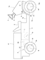
本発明に係る四輪駆動車両、特に四輪駆動運搬車の全体像は、図1に示す如きものである。図2及び図5を参照して図1に示す四輪駆動運搬車を代表例にとりその概略構造を説明する。   An overall view of a four-wheel drive vehicle according to the present invention, particularly a four-wheel drive transport vehicle, is as shown in FIG. A schematic structure of the four-wheel-drive transport vehicle shown in FIG. 1 will be described with reference to FIGS.

この四輪駆動運搬車の機体フレーム1上にはプラットフォーム1bが構成され、その前方にはフロントカバー1aが搭載され、その上部にステアリングハンドル2及び変速(前後進切換)レバー3が突設されている。該ステアリングハンドル2は後述の前輪14の操舵のため、該変速レバー3は、後述の後車軸ハウジング8a内の副変速及び前後進切換機構の操作のために設けられている。また、該フロントカバー1aの足元部の左右一側(右側)にアクセルペダル4が設けられている。なお、フロントカバー1aの足元部の左右他側(左側)には図略のブレーキペダルが設けられている。該機体フレーム1の、プラットフォーム1bより後方部分は一段高くなっていて、その前端上部に運転席5を、その後方に荷台6を搭載している。   A platform 1b is constructed on the body frame 1 of this four-wheel drive vehicle, a front cover 1a is mounted in front of the platform 1b, and a steering handle 2 and a shift (forward / reverse switching) lever 3 project from the top. Yes. The steering handle 2 is provided for steering a front wheel 14 (to be described later), and the shift lever 3 is provided for operating a sub-shift and a forward / reverse switching mechanism in a rear axle housing 8a (to be described later). An accelerator pedal 4 is provided on the left and right side (right side) of the foot portion of the front cover 1a. A brake pedal (not shown) is provided on the left and right other side (left side) of the foot portion of the front cover 1a. A rear portion of the body frame 1 is higher than the platform 1b, and a driver's seat 5 is mounted on the upper front end and a loading platform 6 is mounted on the rear thereof.

該機体フレーム1は、該荷台6の下方にて、前方にエンジン(原動機)7を、後方に後車軸ハウジング8aを支持しており、該後車軸ハウジング8aは、左右一対の後車軸(第一車軸)9を支持し、それぞれ、左右各後輪10に対し、図2に示す如きユニバーサルジョイント11・11及び伝動軸12を介して駆動連結し、さらに機体フレーム1より各後輪10に対し、図示しないサスペンション(コイルバネ、エアシリンダ等)を連結して、該左右後輪10に対し該後車軸ハウジング8aを上下に相対移動可能に支持している。   The fuselage frame 1 supports an engine (prime mover) 7 on the front side and a rear axle housing 8a on the lower side of the loading platform 6, and the rear axle housing 8a is composed of a pair of left and right rear axles (first Axle) 9 is supported, and is connected to each of the left and right rear wheels 10 through universal joints 11 and 11 and a transmission shaft 12 as shown in FIG. Suspensions (coil springs, air cylinders, etc.) not shown are connected to support the rear axle housing 8a so that the rear axle housing 8a can be moved relative to the left and right rear wheels 10 up and down.

後車軸ハウジング8aは、後述の左右後車軸9・9同士を差動連結するデフギア機構34(図2参照)を収納しており、後車軸ハウジング8a外に配した後記のCVTやHST等の無段変速機構等を介して該デフギア機構34をエンジン7に駆動連結する構成により、後車軸駆動装置(第一車軸駆動装置)8を構成している。   The rear axle housing 8a accommodates a differential gear mechanism 34 (see FIG. 2) for differentially connecting the left and right rear axles 9, 9 described later, and there is no CVT, HST or the like described later disposed outside the rear axle housing 8a. A rear axle drive device (first axle drive device) 8 is configured by drivingly connecting the differential gear mechanism 34 to the engine 7 via a step transmission mechanism or the like.

また、該機体フレーム1は、該フロントカバー1aの下方にて、前車軸駆動装置13(第二車軸駆動装置)の前車軸ハウジング13aを支持しており、該前車軸ハウジング13aは、左右一対の前車軸(第二車軸)14を支持し、それぞれ、左右各前輪15に対し、図5に示す如きユニバーサルジョイント16・18及び伝動軸17を介して駆動連結し、さらに機体フレーム1より各前輪15に対し、図示しないサスペンション(コイルバネ、エアシリンダ等)を連結して、該左右前輪15に対し該前車軸ハウジング13を上下に相対移動可能に支持している。   The fuselage frame 1 supports a front axle housing 13a of a front axle drive device 13 (second axle drive device) below the front cover 1a. The front axle housing 13a includes a pair of left and right front axle housings 13a. A front axle (second axle) 14 is supported, and is connected to the left and right front wheels 15 via universal joints 16 and 18 and a transmission shaft 17 as shown in FIG. On the other hand, suspensions (not shown) (coil springs, air cylinders, etc.) are connected to support the front axle housing 13 with respect to the left and right front wheels 15 so as to be relatively movable up and down.

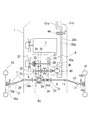
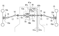
後述の図2〜図4にはそれぞれ後車軸駆動装置8及びそのエンジン7との駆動連係の第一〜第三実施例を、図5〜図9にはそれぞれ前車軸駆動装置13の第二〜第五実施例を描いているが、図1に示す四輪駆動運搬車は、後車軸駆動装置8及びそのエンジン7との駆動連係に関しては図2に示す第一実施例を、前車軸駆動装置13に関しては図5に示す第一実施例を採用している。即ち、図2に示す如く、エンジン7及び後車軸駆動装置8の左右一側にて、エンジン7の出力軸7aと後車軸ハウジング8a内の副変速機構の入力軸21とを、主変速機構たるCVT20にて駆動連結しており、該後車軸ハウジング8aの左右他側に、油圧ポンプ40を取り付けている。一方、前車軸駆動装置13は、図5に示すように、両車軸14間にデフギア機構42(図1では図略)を介設しており、その前方にて、前記油圧ポンプ40より作動油を供給される油圧モータ41を配置している。なお、左右前輪15は操舵可能に支持されており、図1に示す如く、両前輪15間にパワーステアリングシリンダ30が設けられて、前記ハンドル2の操作にてパワーステアリングシリンダ30のピストンを移動させて、両前輪15を操舵する。   2 to 4 to be described later, first to third embodiments of the drive linkage with the rear axle drive device 8 and the engine 7 are respectively shown in FIGS. 2 to 4, and second to second embodiments of the front axle drive device 13 are shown in FIGS. Although the fifth embodiment is illustrated, the four-wheel drive vehicle shown in FIG. 1 is different from the first embodiment shown in FIG. 2 regarding the drive linkage between the rear axle drive device 8 and the engine 7 in the front axle drive device. As for No. 13, the first embodiment shown in FIG. That is, as shown in FIG. 2, the output shaft 7a of the engine 7 and the input shaft 21 of the auxiliary transmission mechanism in the rear axle housing 8a are the main transmission mechanism on the left and right sides of the engine 7 and the rear axle drive device 8. The hydraulic pump 40 is attached to the left and right other sides of the rear axle housing 8a. On the other hand, as shown in FIG. 5, the front axle drive device 13 is provided with a differential gear mechanism 42 (not shown in FIG. 1) between the two axles 14. Is provided. The left and right front wheels 15 are supported so that they can be steered. As shown in FIG. 1, a power steering cylinder 30 is provided between the front wheels 15, and the piston of the power steering cylinder 30 is moved by operating the handle 2. Then, both front wheels 15 are steered.

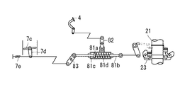
図2に示す後車軸駆動装置8及びそのエンジン7との駆動連係の第一実施例を説明する。前記の入力軸21が左右に延伸されて後車軸ハウジング8a内にて軸支されており、該ハウジング8a内にて、該入力軸21上には回転センサ(ガバナウェイト)23が設けられ、その側方にて、該入力軸21上に、高低二段の副変速ギア、即ち、高速駆動ギア24、低速駆動ギア25を固設し、また、さらにその側方にて、後進駆動ギア26を固設している。   A first embodiment of the drive linkage between the rear axle drive device 8 and its engine 7 shown in FIG. 2 will be described. The input shaft 21 extends left and right and is supported in the rear axle housing 8a. A rotation sensor (governor weight) 23 is provided on the input shaft 21 in the housing 8a. On the side, an auxiliary transmission gear of high and low stages, that is, a high speed drive gear 24 and a low speed drive gear 25 are fixed on the input shaft 21, and a reverse drive gear 26 is further provided on the side. It is fixed.

入力軸21上の回転センサ23は、遠心制御式エンジンガバナを構成すべく、エンジン7のスロットルに連係されており、その入力軸21の回転に伴う開度変化に応じてスロットルの開度が決定される。該スロットルは、前記のアクセルペダル4にも連係されており、アクセルペダル4の踏み込みにてスロットル開度を設定するものであり、入力軸21の実際回転数がその設定に応じた回転数より低くなれば回転センサ23が閉じ気味となり、これを検出してガバナがスロットルの開度を増大し、車速を保つのである。なお、CVT20はエンジン回転数の増大に応じて無段に減速比を小さくする。このエンジンガバナ構造については、図10をもとに後述する。   The rotation sensor 23 on the input shaft 21 is linked to the throttle of the engine 7 so as to form a centrifugal control type engine governor, and the opening of the throttle is determined according to the change in the opening accompanying the rotation of the input shaft 21. Is done. The throttle is also linked to the accelerator pedal 4, and the throttle opening is set by depressing the accelerator pedal 4, and the actual rotational speed of the input shaft 21 is lower than the rotational speed corresponding to the setting. Then, the rotation sensor 23 closes and it is detected, and the governor increases the throttle opening to keep the vehicle speed. Note that the CVT 20 continuously reduces the reduction ratio as the engine speed increases. The engine governor structure will be described later with reference to FIG.

さらに、CVT20には通例の如く、ドリブンプーリに負荷制御用のトルクカム機構(図示せず)を設けている。即ち、走行駆動系の車輪の対地負荷を検出して、エンジンの負担を軽減するためにCVT20の減速比を増大させるのである。   Further, as usual, the CVT 20 is provided with a torque cam mechanism (not shown) for controlling the load on the driven pulley. That is, the ground load of the wheels of the travel drive system is detected, and the reduction ratio of the CVT 20 is increased in order to reduce the load on the engine.

該ハウジング8a内の該入力軸21の下方にて、該入力軸21と平行に出力軸22に高速クラッチギア29、低速クラッチギア30、後進クラッチギア31が遊嵌されており、該高速用クラッチギア29を該高速駆動ギア24に、該低速クラッチギア30を該低速駆動ギア25に常時噛合させている。また、該ハウジング8a内に、該入力軸21・出力軸22と平行にアイドラギア軸28が軸支されていて、該アイドラ軸28上に設けたアイドラギア27が、該後進用駆動ギア26及び該後進用クラッチギア31に噛合している。   A high-speed clutch gear 29, a low-speed clutch gear 30, and a reverse clutch gear 31 are loosely fitted to the output shaft 22 in parallel with the input shaft 21 below the input shaft 21 in the housing 8a. The gear 29 is always meshed with the high-speed drive gear 24 and the low-speed clutch gear 30 is meshed with the low-speed drive gear 25 at all times. An idler gear shaft 28 is supported in the housing 8a in parallel to the input shaft 21 and the output shaft 22, and an idler gear 27 provided on the idler shaft 28 is connected to the reverse drive gear 26 and the reverse drive gear. The clutch gear 31 is engaged.

該出力軸22上にはさらに、軸芯方向に摺動可能かつ相対回転不能にクラッチスライダ32を設けており、該クラッチスライダ32を摺動させて、該高速クラッチギア29、該低速クラッチギア30、該後進クラッチギア31のいずれかに噛合させるものとしている。また、該クラッチスライダ32は、出力軸22に対する入力軸21の回転動力の伝達を絶つべく該ギア29・30・31のいずれにも噛合しないようにも配置される。このクラッチスライダ32は前記の変速レバー3に操作連係されている。   Further, a clutch slider 32 is provided on the output shaft 22 so as to be slidable in the axial direction and not relatively rotatable. The high speed clutch gear 29 and the low speed clutch gear 30 are slid by sliding the clutch slider 32. The reverse clutch gear 31 is meshed. Further, the clutch slider 32 is arranged so as not to mesh with any of the gears 29, 30, 31 so as to cut off transmission of the rotational power of the input shaft 21 to the output shaft 22. The clutch slider 32 is operatively linked to the speed change lever 3.

該出力軸22にはピニオン33が固設され、デフギア機構34のブルギア34bに噛合している。該デフギア機構34は、左右両車軸9・9間に配置されて、両車軸9・9同士を差動連結している。出力軸22上のピニオン33が左右一側に寄っている関係上、ブルギア34bは、その側の一車軸9上に遊嵌されているが、ピニオンとの位置関係によっては両車軸9・9の内端突き合わせ部分上に配設してもよい。もう一方の車軸9上にはデフロック部材34aが設けられており、適時に、該デフギア機構34のデフケースに相対回転不能に嵌合して、両車軸9・9同士を差動不能に連結する。   A pinion 33 is fixed to the output shaft 22 and meshes with a bull gear 34 b of a differential gear mechanism 34. The differential gear mechanism 34 is disposed between the left and right axles 9, 9, and differentially connects the axles 9, 9. The bull gear 34b is loosely fitted on one axle 9 on the side where the pinion 33 on the output shaft 22 is shifted to the left and right side, but depending on the positional relationship with the pinion, both axles 9 and 9 You may arrange | position on an inner-end butting | matching part. A differential lock member 34a is provided on the other axle 9 and is fitted to the differential case of the differential gear mechanism 34 in a relatively non-rotatable manner at an appropriate time to connect the two axles 9 and 9 in a differential manner.

ハウジングに支持される車軸が車輪の中心まで延伸されている構造のものでは、一般に該ハウジング内にて左右各車軸上に湿式多板型ブレーキを設けるが、本実施例の後車軸ハウジング8aは、前述の如く、サスペンションにて後輪10・10に対し上下移動可能に支持されているため、ハウジング内部のブレーキ構造は不適である。そこで、各後輪10の中心軸に乾式単板型ブレーキ10bを付設している。両ブレーキ10bは油圧的あるいは機械的に前述の図略のブレーキペダルに操作連係されている。   In the structure in which the axle supported by the housing extends to the center of the wheel, a wet multi-plate brake is generally provided on each of the left and right axles in the housing. As described above, since the suspension is supported so as to be movable up and down with respect to the rear wheels 10 and 10, the brake structure inside the housing is not suitable. Therefore, a dry single-plate brake 10b is attached to the central axis of each rear wheel 10. Both brakes 10b are hydraulically or mechanically linked to a brake pedal (not shown).

出力軸22は、PTO軸として、CVT20への入力軸21の突出側とは左右反対側に、該前車軸ハウジング8aより突出しており、該前車軸ハウジング8aの当該左右側に付設したポンプハウジング8b内に設けた油圧ポンプ40のポンプ軸40aに、スリーブ状のカップリングによるスプライン嵌合等の手段により、同一軸芯上にて相対回転不能に係合されている。   The output shaft 22 projects as a PTO shaft from the front axle housing 8a on the opposite side to the projecting side of the input shaft 21 to the CVT 20, and is provided on the left and right sides of the front axle housing 8a. The pump shaft 40a of the hydraulic pump 40 provided therein is engaged with the pump shaft 40a by means of spline fitting with a sleeve-like coupling and the like so as not to rotate relative to each other on the same axis.

この油圧ポンプ40より、好ましくは油圧管にて構成される一対の給排用油路50a・50bが延設されて、駆動モード切換バルブ44に接続され、また、該駆動モード切換バルブ44に、前車軸駆動装置13の油圧モータ41より、好ましくは油圧管にて構成される一対の給排用油路51a・51bが接続されている。   From this hydraulic pump 40, a pair of supply / discharge oil passages 50a and 50b, preferably constituted by hydraulic pipes, are extended and connected to the drive mode switching valve 44. A pair of oil supply / discharge oil passages 51a and 51b, preferably constituted by hydraulic pipes, are connected to the front axle drive device 13 by a hydraulic motor 41.

駆動モード切換バルブ44は、二輪駆動位置と四輪駆動位置とに切り換えられる。四輪駆動位置にある時は、油路50a・51a同士、油路50b・51b同士が接続されて、後車軸駆動装置8に付設した油圧ポンプ40と前車軸駆動装置13の油圧モータ41とを油圧接続して、HSTを構成し、後車軸駆動装置8の動力を前車軸駆動装置13に伝達して、運搬車を四輪駆動にて走行させる。   The drive mode switching valve 44 is switched between a two-wheel drive position and a four-wheel drive position. When in the four-wheel drive position, the oil passages 50a and 51a and the oil passages 50b and 51b are connected, and the hydraulic pump 40 attached to the rear axle drive device 8 and the hydraulic motor 41 of the front axle drive device 13 are connected. Hydraulically connected to form the HST, the power of the rear axle drive device 8 is transmitted to the front axle drive device 13, and the transport vehicle is driven by four-wheel drive.

二輪駆動位置にある時は、油路50a・50b同士、油路51a・51b同士が接続されて、油圧ポンプ40・油圧モータ41それぞれ独立の循環回路を構成し、前車軸駆動装置13を後車軸駆動装置8の駆動力より隔離して、運搬車を後輪のみの駆動にて走行させる。なお、油路50a・50b同士の接続により、油圧ポンプ40は出力軸22の回転につれて自由に回転し、油路51a・51b同士の接続により、油圧モータ41は前輪15が後輪10の駆動に伴って転動するのにつれて自由に回転する。   When in the two-wheel drive position, the oil passages 50a and 50b and the oil passages 51a and 51b are connected to each other to form an independent circulation circuit for each of the hydraulic pump 40 and the hydraulic motor 41, and the front axle drive device 13 is connected to the rear axle. In isolation from the driving force of the driving device 8, the transport vehicle is driven by driving only the rear wheels. The hydraulic pump 40 freely rotates as the output shaft 22 rotates due to the connection between the oil passages 50a and 50b, and the hydraulic motor 41 allows the front wheel 15 to drive the rear wheel 10 due to the connection between the oil passages 51a and 51b. It rotates freely as it rolls with it.

なお、油圧ポンプ40は、後車軸ハウジング8a内の副変速機構の下手側の出力軸22、即ち、クラッチスライダ32をいずれの位置にするかにより回転速度や回転方向が切り換わる出力軸22をポンプ軸として共用するので、油圧ポンプ40の駆動速度及び方向を、該副変速機構による後輪10の速度や駆動方向の変化に対応させることができ、従って、前車軸駆動装置13に特別な機構を設けることなく容易に前輪15の駆動を後輪10の駆動に同期させることができる。   The hydraulic pump 40 pumps the output shaft 22 on the lower side of the auxiliary transmission mechanism in the rear axle housing 8a, that is, the output shaft 22 whose rotational speed and direction are switched depending on which position the clutch slider 32 is set to. Since the shaft is shared, the drive speed and direction of the hydraulic pump 40 can be made to correspond to changes in the speed and drive direction of the rear wheel 10 by the auxiliary transmission mechanism, and therefore a special mechanism is provided in the front axle drive device 13. Without being provided, the driving of the front wheel 15 can be easily synchronized with the driving of the rear wheel 10.

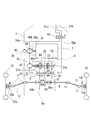
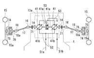
図3に示す後車軸駆動装置8及びそのエンジン7との駆動連係の第二実施例を説明する。図2に示す第一実施例のものと同一部材または同一機能を有する部材については同一符号を付しており、これらについての説明は省略する。本実施例の後車軸駆動装置8は、エンジン7に対し、CVTではなく、HSTにて駆動連係されている。このHSTは、エンジン7の出力軸7aをポンプ軸としてエンジン7に付設した油圧ポンプ40と、後車軸駆動装置8の入力軸21をモータ軸として後車軸ハウジング8に付設した油圧モータ45とを油圧回路にて接続することで構成されている。   A second embodiment of the drive linkage between the rear axle drive device 8 and its engine 7 shown in FIG. 3 will be described. The same members or members having the same functions as those of the first embodiment shown in FIG. 2 are denoted by the same reference numerals, and description thereof will be omitted. The rear axle drive device 8 of the present embodiment is linked to the engine 7 by HST instead of CVT. The HST hydraulically operates a hydraulic pump 40 attached to the engine 7 using the output shaft 7a of the engine 7 as a pump shaft, and a hydraulic motor 45 attached to the rear axle housing 8 using the input shaft 21 of the rear axle drive device 8 as a motor shaft. It is configured by connecting with a circuit.

エンジン7の一側面にはポンプハウジング7bが付設されていて、この中に出力軸7aが突入し、油圧ポンプ40のポンプ軸41aを、スリーブ状のカップリングによるスプライン嵌合等の手段により、同一軸芯上にて相対回転不能に該出力軸7aに接続している。さらに、該ポンプ軸41aは、ともに該ポンプハウジング7b内に収納したチャージポンプ43の駆動軸として兼用されている。チャージポンプ43から吐出される油は、HSTの補充油として用いる他、前述のステアリングシリンダ30等の駆動用として用いることができる。   A pump housing 7b is attached to one side of the engine 7, and an output shaft 7a is inserted into the pump housing 7b. The pump shaft 41a of the hydraulic pump 40 is made identical by means such as spline fitting by a sleeve-like coupling. The shaft is connected to the output shaft 7a so as not to rotate relative to the shaft core. Further, the pump shaft 41a is also used as a drive shaft for the charge pump 43 housed in the pump housing 7b. The oil discharged from the charge pump 43 can be used for driving the aforementioned steering cylinder 30 or the like, in addition to being used as HST replenishment oil.

後車軸ハウジング8aの左右側端のうち、ポンプハウジング7bと同一側にモータハウジング8cが付設され、この中に入力軸21が突入し、これに油圧モータ45のモータ軸45aを、スリーブ状のカップリングによるスプライン嵌合等の手段により、同一軸芯上にて相対回転不能に接続している。この油圧モータ45は実施例では互いに流体接続する前記油圧ポンプ40と離間された状態にあるが共通のハウジングに収納して、エンジン7側もしくは後車軸ハウジング8a側の方へ集中配置しても良い。   A motor housing 8c is attached to the left and right ends of the rear axle housing 8a on the same side as the pump housing 7b, and the input shaft 21 is inserted into the motor housing 8c, and the motor shaft 45a of the hydraulic motor 45 is inserted into the sleeve-shaped cup. By means such as spline fitting by a ring, they are connected so that they cannot rotate relative to each other on the same axis. In the embodiment, the hydraulic motor 45 is separated from the hydraulic pumps 40 that are fluidly connected to each other. However, the hydraulic motor 45 may be housed in a common housing and concentrated on the engine 7 side or the rear axle housing 8a side. .

油圧ポンプ40と駆動モード切換バルブ44とを結ぶ一対の給排油路50a・50bのうち、油路50bの途中部に油圧モータ45を介設するものとしており、油圧ポンプ40と油圧モータ45との間の油路50bは、好ましくはポンプハウジング7b・モータハウジング8cとの間に介設した油圧管等にて構成されている。そして、油路50a及び油圧モータ45・駆動モード切換バルブ44間の油路50bを、それぞれ、好ましくは、ポンプハウジング7b・モータハウジング8cより延設される油圧管にて構成している。また、駆動モード切換バルブ44には前述と同様に、前車軸駆動装置13の油圧モータ41からの油路51a・51bが接続されている。   Of the pair of supply / discharge oil passages 50a and 50b connecting the hydraulic pump 40 and the drive mode switching valve 44, a hydraulic motor 45 is provided in the middle of the oil passage 50b. The oil passage 50b is preferably constituted by a hydraulic pipe or the like interposed between the pump housing 7b and the motor housing 8c. The oil passage 50a and the oil passage 50b between the hydraulic motor 45 and the drive mode switching valve 44 are preferably constituted by hydraulic pipes extending from the pump housing 7b and the motor housing 8c, respectively. The drive mode switching valve 44 is connected to the oil passages 51a and 51b from the hydraulic motor 41 of the front axle drive device 13 in the same manner as described above.

駆動モード切換バルブ44を四輪駆動位置にすると、油路50a・51a同士、油路50b・51b同士を接続して、一つの油圧ポンプ40に対し二つの油圧モータ41・45を直列接続したHSTを構成する。即ち、油圧ポンプ40の吐出油が後輪10駆動用の油圧モータ45と前輪15駆動用の油圧モータ41とに供給され、運搬車は四輪駆動にて走行する。一方、駆動モード切換バルブ44を二輪駆動位置にすると、油路50a・50b同士、油路51a・51b同士が接続され、後輪10駆動用の、油圧ポンプ40・モータ45よりなるHSTが構成されるとともに、前輪15駆動用の油圧モータ41は、該油圧ポンプ40からの圧油を受けず、運搬車は二輪駆動にて走行する。   When the drive mode switching valve 44 is set to the four-wheel drive position, the oil passages 50a and 51a, the oil passages 50b and 51b are connected, and two hydraulic motors 41 and 45 are connected in series to one hydraulic pump 40. Configure. That is, the oil discharged from the hydraulic pump 40 is supplied to the hydraulic motor 45 for driving the rear wheel 10 and the hydraulic motor 41 for driving the front wheel 15, and the transport vehicle travels by four-wheel drive. On the other hand, when the drive mode switching valve 44 is set to the two-wheel drive position, the oil passages 50a and 50b and the oil passages 51a and 51b are connected to each other, and the HST including the hydraulic pump 40 and the motor 45 for driving the rear wheel 10 is configured. At the same time, the hydraulic motor 41 for driving the front wheels 15 does not receive the pressure oil from the hydraulic pump 40, and the transport vehicle travels by two-wheel drive.

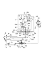
後車軸駆動装置8においては、油圧ポンプ40を可変容積型とし、その可動斜板40bの傾斜方向を切り換えることで、その吐出方向を切り換え、油圧モータ45・41の回転方向を切り換えることができるので、第一実施例の如きハウジング8a内における入力軸21・出力軸22間の後進用ギア列は不要となる。その分、ハウジング8a内の入力軸21上にスペース的な余裕ができ、これを利用して、油圧ポンプ40の容積を走行時にかかる後輪10の負荷に応じて制御とするためのトルクセンサ60を入力軸21上に設けている。なお、正確には該入力軸21は、トルクセンサ60によるトルク検出のために、油圧モータ45側の第一部21aと、デフギア機構34側の第二部21bとに分割されており、低速駆動ギア25・高速駆動ギア24・回転センサ23を第二部21b上に設けている。即ち、入力軸21の第一部21a・第二部21bの軸回りの相対変位を推力に変換して後輪10の負荷トルクを検出するのである。   In the rear axle drive device 8, the hydraulic pump 40 is of a variable displacement type, and by switching the tilt direction of the movable swash plate 40b, the discharge direction can be switched and the rotation direction of the hydraulic motors 45 and 41 can be switched. The reverse gear train between the input shaft 21 and the output shaft 22 in the housing 8a as in the first embodiment is not necessary. Accordingly, a space is provided on the input shaft 21 in the housing 8a, and the torque sensor 60 is used to control the volume of the hydraulic pump 40 according to the load of the rear wheel 10 applied during traveling. Are provided on the input shaft 21. To be precise, the input shaft 21 is divided into a first part 21a on the hydraulic motor 45 side and a second part 21b on the differential gear mechanism 34 side for torque detection by the torque sensor 60, and is driven at low speed. A gear 25, a high-speed drive gear 24, and a rotation sensor 23 are provided on the second portion 21b. That is, the load torque of the rear wheel 10 is detected by converting the relative displacement around the axis of the first portion 21a and the second portion 21b of the input shaft 21 into thrust.

トルクセンサ60は油圧ポンプ40の可動斜板40bに(電気式或いは機械式に)操作連係されており、該トルクセンサ60が設定値以上の負荷トルクを検出すると、それに応じて可動斜板40bが減速側に移動する構成となっている。この油圧ポンプ40の負荷制御は後に図12をもとに詳述する。一方、回転センサ23は前記同様にエンジン7のスロットルに操作連係されていて、エンジンガバナを構成している。なお、エンジン負荷に応じたHSTの制御については、トルク検出に代えて、HSTの油圧検出に基づく方法もある。これらの構成については図10以降の図面をもとに後述する。   The torque sensor 60 is operatively linked (electrically or mechanically) to the movable swash plate 40b of the hydraulic pump 40, and when the torque sensor 60 detects a load torque greater than a set value, the movable swash plate 40b is correspondingly moved. It is configured to move to the deceleration side. The load control of the hydraulic pump 40 will be described in detail later with reference to FIG. On the other hand, the rotation sensor 23 is linked to the throttle of the engine 7 in the same manner as described above, and constitutes an engine governor. For HST control according to engine load, there is a method based on HST oil pressure detection instead of torque detection. These configurations will be described later with reference to FIG. 10 and subsequent drawings.

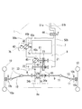
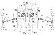
図4に示す後車軸駆動装置8及びそのエンジン7との駆動連係の第三実施例を説明する。図2・図3に示す第一・第二実施例のものと同一部材または同一機能を有する部材については同一符号を付しており、これらについての説明は省略する。本実施例では、後車軸駆動装置8のエンジン7に対する駆動連係を、第二実施例と同様に、HSTによるものとしている。即ち、エンジン7の出力軸7aをポンプ軸としてエンジン7に付設した油圧ポンプ40と、後車軸ハウジング8に支持される入力軸21をモータ軸とする油圧モータ45とを油圧回路にて接続したものである。この油圧ポンプ40の吐出油は、第二実施例同様に、駆動モード切換バルブ44を介して、前車軸駆動装置13の油圧モータ41にも供給可能となっている。   A third embodiment of the drive linkage between the rear axle drive device 8 and its engine 7 shown in FIG. 4 will be described. The same members or members having the same functions as those in the first and second embodiments shown in FIGS. 2 and 3 are denoted by the same reference numerals, and description thereof will be omitted. In the present embodiment, the drive linkage of the rear axle drive device 8 to the engine 7 is based on HST, as in the second embodiment. That is, a hydraulic pump 40 attached to the engine 7 using the output shaft 7a of the engine 7 as a pump shaft and a hydraulic motor 45 having the input shaft 21 supported by the rear axle housing 8 as a motor shaft connected by a hydraulic circuit. It is. The oil discharged from the hydraulic pump 40 can be supplied to the hydraulic motor 41 of the front axle drive device 13 via the drive mode switching valve 44 as in the second embodiment.

第二実施例と異なる点として、第二実施例の油圧モータ45は固定容積型であり、後車軸ハウジング8aに外付けされていたが、本実施例の油圧モータ45は可動斜板45aを有する可変容積型であり、後車軸ハウジング8a内に収納されている。即ち、油圧ポンプ40の可動斜板40bの位置制御によるHSTの減速比制御を主変速として割り当てる一方で、油圧モータ45の可動斜板45aの位置制御によってさらに副変速としてのHSTの減速比制御を行っている。   As a difference from the second embodiment, the hydraulic motor 45 of the second embodiment is a fixed displacement type and is externally attached to the rear axle housing 8a. However, the hydraulic motor 45 of this embodiment has a movable swash plate 45a. It is a variable displacement type and is accommodated in the rear axle housing 8a. That is, while the HST reduction ratio control by the position control of the movable swash plate 40b of the hydraulic pump 40 is assigned as the main shift, the HST reduction ratio control as a sub-shift is further performed by the position control of the movable swash plate 45a of the hydraulic motor 45. Is going.

これにより、後車軸ハウジング8a内において、第二実施例に示す如き副変速用の高低ギア列は不要となり、その分、該ハウジング8a内に余裕ができることから、前述のように油圧モータ45を該ハウジング8a内に収納できるのであり、前車軸駆動装置8全体のさらなるコンパクト化を実現している。   This eliminates the need for the auxiliary gear shift train as shown in the second embodiment in the rear axle housing 8a, and as a result, there is room in the housing 8a. Since it can be accommodated in the housing 8a, the front axle drive device 8 as a whole can be further downsized.

なお、本実施例の後車軸ハウジング8a内においては、油圧モータ45のモータ軸として延伸される入力軸21に小径ギア61を固設するとともに回転センサ23を設けており、出力軸22上に、該小径ギア61と常時噛合する大径ギア62を遊嵌して、両軸21・22間に減速ギア列を構成しており、該大径ギア62と出力軸22との間にはトルクセンサ60を介設している。即ち、本実施例でのトルクセンサ60は、入力軸21に常時ギア噛合する大径ギア61と、デフギア機構43に常時ギア噛合する出力軸22との相対回転差を検知して負荷トルクを検出する。   In the rear axle housing 8a of this embodiment, a small-diameter gear 61 is fixed to the input shaft 21 that is extended as the motor shaft of the hydraulic motor 45, and a rotation sensor 23 is provided. A large-diameter gear 62 that always meshes with the small-diameter gear 61 is loosely fitted to form a reduction gear train between the shafts 21 and 22, and a torque sensor is provided between the large-diameter gear 62 and the output shaft 22. 60 is interposed. That is, the torque sensor 60 in this embodiment detects the load torque by detecting the relative rotational difference between the large-diameter gear 61 that is always in gear engagement with the input shaft 21 and the output shaft 22 that is always in gear engagement with the differential gear mechanism 43. To do.

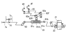
次に、図5に示す前車軸駆動装置13の第一実施例を説明する。前車軸ハウジング13a内に機械式デフギア機構70が設けられていて、左右前車軸14・14同士を差動連結している。一方の前車軸14上にはデフロック部材70aを設けている。デフギア機構70のブルギア70bは、その前方にて前車軸ハウジング13a内に収容した油圧モータ41のモータ軸41aに固設したモータギア41cに常時噛合している。   Next, a first embodiment of the front axle drive device 13 shown in FIG. 5 will be described. A mechanical differential gear mechanism 70 is provided in the front axle housing 13a, and the left and right front axles 14, 14 are differentially connected to each other. On one front axle 14, a differential lock member 70a is provided. The bull gear 70b of the differential gear mechanism 70 always meshes with a motor gear 41c fixed to the motor shaft 41a of the hydraulic motor 41 housed in the front axle housing 13a in front of the differential gear mechanism 70.

油圧モータ41への一対の給排ポートが前車軸ハウジング13a外側に設けられていて、前述の油圧ポンプ40との間で作動油を循環させるための油路51a・51bが油圧管等で構成されて、駆動モード切換バルブ44より延設され、該給排ポートに接続される。こうして、油圧モータ41が駆動されることにより、デフギア機構70を介して左右車軸14・14を駆動するものである。   A pair of supply / discharge ports for the hydraulic motor 41 is provided outside the front axle housing 13a, and oil passages 51a and 51b for circulating hydraulic oil to and from the hydraulic pump 40 are configured by hydraulic pipes or the like. The drive mode switching valve 44 extends and is connected to the supply / discharge port. Thus, the left and right axles 14 and 14 are driven via the differential gear mechanism 70 by driving the hydraulic motor 41.

なお、油圧モータ41は可変容積型であって、前記ハンドル2から操舵輪たる前輪15までのリンク機構のいずれかの部位に操作連係される可動斜板41bを具備しており、ハンドル2の切り角の増大に応じて可動斜板41bが増速側に傾動するように構成して旋回時の前輪と後輪との軌跡に応じた理想的な回転数に近づけるように前輪10を速度制御している。これについては、後述の図6〜図8に示す第二〜第四実施例でも同様である。   The hydraulic motor 41 is a variable displacement type, and includes a movable swash plate 41b that is operatively linked to any part of the link mechanism from the handle 2 to the front wheel 15 that is the steering wheel. As the angle increases, the movable swash plate 41b tilts to the speed increasing side, and the speed of the front wheel 10 is controlled so as to approach the ideal rotational speed according to the trajectory between the front wheel and the rear wheel during turning. ing. The same applies to second to fourth embodiments shown in FIGS. 6 to 8 described later.

各車軸14と各前輪15との間の駆動連結は、前述の如くユニバーサルジョイント16・18及び伝動軸17によるものであり、各ユニバーサルジョイント18に連結される各前輪15の中心軸15a上には乾式単板型のブレーキ15bが付設されている。   The drive connection between each axle 14 and each front wheel 15 is by the universal joints 16 and 18 and the transmission shaft 17 as described above. On the central shaft 15a of each front wheel 15 connected to each universal joint 18, A dry single plate type brake 15b is attached.

なお、前輪15は後輪10によって地面から駆動されるときの回転数と油圧モータ41により駆動されるときの回転数とが同期していれば問題はないが、例えば、発進直後などでは油圧ポンプ40の回転数が低く、この少量の吐出油を受けて駆動される油圧モータ41の回転数は低回転状態における容積効率特性により、地面からの摩擦を受けて駆動される前輪15の回転数よりも低くなる。そのため、前輪15に油圧モータ41が連れ回り、油圧モータ41が油圧ポンプ40を逆駆動する背圧現象が生じる。これは、出力軸22にブレーキング作用を与え走行安定性を極端に悪化させるので、前輪15から油圧モータ41方向へのみ駆動力伝達を防止すべく、各前車軸15と、該前車軸15を伝動軸17に連結するユニバーサルジョイント16との間にて、ワンウェイクラッチもしくはツーウェイクラッチ71を介設している。   There is no problem as long as the rotation speed when the front wheel 15 is driven from the ground by the rear wheel 10 and the rotation speed when driven by the hydraulic motor 41 are synchronized. The rotational speed of the hydraulic motor 41 driven by receiving this small amount of discharged oil is lower than the rotational speed of the front wheel 15 driven by friction from the ground due to the volumetric efficiency characteristic in the low rotational state. Also lower. Therefore, a back pressure phenomenon occurs in which the hydraulic motor 41 rotates with the front wheel 15 and the hydraulic motor 41 reversely drives the hydraulic pump 40. This gives the braking action to the output shaft 22 and extremely deteriorates the running stability. Therefore, in order to prevent the driving force from being transmitted only from the front wheels 15 toward the hydraulic motor 41, each front axle 15 and the front axle 15 are connected to each other. A one-way clutch or a two-way clutch 71 is interposed between the universal joint 16 connected to the transmission shaft 17.

このツーウェイクラッチ71は、例えば、入力側の内輪と出力側外輪との間に、内外側部分にカム面が形成されたトルク伝達部材である複数のスプラグを円周方向に沿って配置し、各スプラグを、内外輪間に介在させた外側保持器と内側保持器とで保持した状態で内外輪の周面に対して係合・離脱可能とした構造をしている。スプラグが内外輪間で起立した中立状態では、スプラグのカム面が内外輪の周面から離脱し、これにより、内輪からの回転トルクを遮断して前輪15から前車軸14への向きの動力伝達を防止する。一方、内側保持器に対する外側保持器の差動回転によりスプラグが所定量傾動すると、そのスプラグのカム面が内外輪の周面に圧接係合し、これにより、内輪からの回転トルクをスプラグを介して外輪に伝達して、前車軸14の前進回転及び後進回転を前輪15へと伝達するのを許容している。このツーウェイクラッチ71は、開示した実施例の他に、前車軸ハウジング13a内のデフギア機構70におけるサイドベベルギアと前車軸14との間、或いは、前輪15とその中心軸15aとの間に配設することもできる。   In the two-way clutch 71, for example, a plurality of sprags, which are torque transmission members having cam surfaces formed on the inner and outer portions, are arranged along the circumferential direction between the inner ring on the input side and the outer ring on the output side. The sprag is structured to be engageable and disengageable with respect to the peripheral surface of the inner and outer rings while being held by the outer and inner cages interposed between the inner and outer rings. In the neutral state where the sprag stands between the inner and outer wheels, the cam surface of the sprag is detached from the peripheral surface of the inner and outer wheels, thereby interrupting the rotational torque from the inner ring and transmitting power in the direction from the front wheel 15 to the front axle 14. To prevent. On the other hand, when the sprag is tilted by a predetermined amount due to the differential rotation of the outer cage with respect to the inner cage, the cam surface of the sprag is pressed into contact with the peripheral surface of the inner and outer rings, and thereby rotational torque from the inner ring is transmitted via the sprag. Thus, the forward rotation and the reverse rotation of the front axle 14 are allowed to be transmitted to the front wheel 15. In addition to the disclosed embodiment, the two-way clutch 71 is disposed between the side bevel gear and the front axle 14 in the differential gear mechanism 70 in the front axle housing 13a, or between the front wheel 15 and the central shaft 15a. You can also

これらのクラッチ71は、特に、後車軸駆動装置8が前述の第一実施例の如き構成である時のように、後輪駆動用の伝動軸をポンプ軸とする油圧ポンプ40と前輪駆動用の油圧モータ41とが1対1で流体接続されてHSTを構成しており、前輪15と後輪10との駆動が完全には同期しない構造の場合に有効である。一方、後車軸駆動装置8が前述の第二・第三実施例のような場合には、一つの油圧ポンプ40に対して、前輪駆動用油圧モータ41と後輪駆動用油圧モータ45とが直列で接続されているため、両モータ41・45の駆動、即ち、前輪15・後輪10の駆動が略完全に同期されるものについては不要である。図6〜図9の前車軸駆動装置13の各実施例にもクラッチ71を開示しているが、同様であって、第二・第三実施例の後車軸駆動装置8と組み合わせる場合には削除してもよい。   In particular, the clutch 71 includes a hydraulic pump 40 having a rear shaft driving transmission shaft as a pump shaft and a front wheel driving device, as in the case where the rear axle driving device 8 is configured as in the first embodiment. This is effective when the hydraulic motor 41 is fluidly connected in a one-to-one manner to form an HST, and the driving of the front wheel 15 and the rear wheel 10 is not completely synchronized. On the other hand, when the rear axle driving device 8 is as in the second and third embodiments described above, a front wheel driving hydraulic motor 41 and a rear wheel driving hydraulic motor 45 are connected in series to one hydraulic pump 40. Therefore, it is unnecessary for the motors 41 and 45 to be driven, that is, the front wheels 15 and the rear wheels 10 are substantially completely synchronized. The clutch 71 is also disclosed in each of the embodiments of the front axle drive device 13 of FIGS. 6 to 9, but it is the same and is deleted when combined with the rear axle drive device 8 of the second and third embodiments. May be.

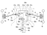
前車軸駆動装置13についての図6〜9の第二〜第五実施例は、それぞれ、図5に示したような機械式デフギア機構70を除いて、左右各車軸14に対し各別に設けた一対の油圧モータ41・41間の油圧的な差動で、左右前輪15・15の差動回転を許容する。但し、この場合、該一対の油圧モータ41・41を油圧ポンプ40に対し並列で接続するが、左右前輪15・15のいずれかに負荷がかかった場合、負荷の小さい方の前輪15駆動用の油圧モータ41に多くの油が流れ、負荷の大きい方の前輪15側の油圧モータ41を流れる油は少なくなる現象による。このことは次のような不具合が生じる可能性がある。例えば、一方の前輪15が溝にはまると、はまった前輪15の負荷が極端に小さくなるので、この前輪15用の油圧モータ41ばかりに油が供給され、溝にはまっていない前輪15用の油圧モータ41が駆動されず、脱出ができないこととなる。   6 to 9 of the front axle drive device 13 are respectively a pair provided separately for the left and right axles 14 except for the mechanical differential gear mechanism 70 as shown in FIG. The hydraulic differential between the hydraulic motors 41 and 41 allows differential rotation of the left and right front wheels 15 and 15. However, in this case, the pair of hydraulic motors 41 and 41 are connected in parallel to the hydraulic pump 40. However, when a load is applied to either the left or right front wheels 15 or 15, the front wheel 15 for driving the smaller front wheel 15 is used. This is because a large amount of oil flows through the hydraulic motor 41 and less oil flows through the hydraulic motor 41 on the front wheel 15 side with the larger load. This can cause the following problems. For example, when one of the front wheels 15 is fitted into a groove, the load on the fitted front wheel 15 is extremely reduced, so that oil is supplied only to the hydraulic motor 41 for the front wheel 15 and the hydraulic pressure for the front wheel 15 that does not fit in the groove. The motor 41 is not driven and cannot escape.

図6〜9の各実施例は、このような不具合を解消すべく、両油圧モータ41・41間の差動を制限する手段を設けている。特にこのことを中心に、前車軸駆動装置13の第二〜第五各実施例を説明する。   Each of the embodiments shown in FIGS. 6 to 9 is provided with means for limiting the differential between the hydraulic motors 41 and 41 in order to eliminate such a problem. In particular, focusing on this, the second to fifth embodiments of the front axle drive device 13 will be described.

まず、図6、図7の第二・第三各実施例においては、駆動モード切換バルブ44に接続される油路51a・51b間に、両油圧モータ41・41を並列に接続するための並列回路を介在させるものであり、該並列回路は、両油圧モータ41・41を介して、油路51a側に接続する分岐油路52・52と、油路51b側に接続する分岐油路53・53とよりなる。図8、図9の第四・第五実施例は、基本的に駆動モード切換バルブ44を介して油圧ポンプ40に両油圧モータ41・41を並列接続することは同じであるが、この回路構成を改変することで両モータ41・41間の差動制限手段としており、これについては後に詳述する。   First, in each of the second and third embodiments shown in FIGS. 6 and 7, the two hydraulic motors 41 and 41 are connected in parallel between the oil passages 51 a and 51 b connected to the drive mode switching valve 44. The parallel circuit includes, via both hydraulic motors 41 and 41, branch oil passages 52 and 52 connected to the oil passage 51a side, and branch oil passages 53 and 52 connected to the oil passage 51b side. 53. In the fourth and fifth embodiments shown in FIGS. 8 and 9, basically, both hydraulic motors 41 and 41 are connected in parallel to the hydraulic pump 40 via the drive mode switching valve 44. Is used as means for limiting the differential between the motors 41 and 41, which will be described in detail later.

図6に示す第二実施例においては、両油圧モータ41・41の各モータ軸をそのまま前車軸14と(或いは同一軸芯上に配して各前車軸14に駆動接続)して、左右外側に延設しており、各モータ軸41aを左右内側に延長し、その内側延長部41a同士を機械式のリミティッドスリップ機構73により接続して、両モータ軸間の差動を制限している。   In the second embodiment shown in FIG. 6, the motor shafts of both hydraulic motors 41 and 41 are directly connected to the front axle 14 (or arranged on the same axis and drivingly connected to the front axle 14), and left and right outer sides. The motor shafts 41a are extended to the left and right inner sides, and the inner extensions 41a are connected to each other by a mechanical limited slip mechanism 73 to limit the differential between the motor shafts.

各前輪15と、該前輪15を伝動軸17に接続する各ユニバーサルジョイント18との間には、減速ギアケース74が介設されている。該減速ギアケース74内には、ユニバーサルジョイント18からの伝動軸18aと、該前輪15の中心軸15aとが対向状に突入しており、両軸18a・15a間に遊星ギア式の減速ギア機構75が介設されている。なお、両軸18a・15a間の減速機構はこの構成には限らない。該減速ギアケース74内において、該伝動軸18a上に、好ましくは乾式単板型のブレーキ76が設けられている。   A reduction gear case 74 is interposed between each front wheel 15 and each universal joint 18 that connects the front wheel 15 to the transmission shaft 17. In the reduction gear case 74, the transmission shaft 18a from the universal joint 18 and the central shaft 15a of the front wheel 15 protrude in an opposing manner, and a planetary gear type reduction gear mechanism is provided between the shafts 18a and 15a. 75 is interposed. Note that the speed reduction mechanism between the shafts 18a and 15a is not limited to this configuration. In the reduction gear case 74, a dry single plate brake 76 is preferably provided on the transmission shaft 18a.

図7に示す第三実施例においては、モータ軸41a・41a同士を機械式リミティッドスリップ機構73で連結する一方、後車軸ハウジング13a内において、各前車軸14は各油圧モータ41のモータ軸41aに平行に軸支されており、各モータ軸41a上に固設した小径ギア77と、各前車軸14上の大径ギア78とを噛合させて減速ギア列を構成している。   In the third embodiment shown in FIG. 7, the motor shafts 41 a and 41 a are connected to each other by a mechanical limited slip mechanism 73, while each front axle 14 is connected to the motor shaft 41 a of each hydraulic motor 41 in the rear axle housing 13 a. A reduction gear train is constituted by a small-diameter gear 77 fixed on each motor shaft 41a and a large-diameter gear 78 on each front axle 14 that are supported in parallel.

これにより、第二実施例に示したような前輪15とユニバーサルジョイント18との間の減速ギアケース74は省いて、該前輪15の中心軸15aを直接ユニバーサルジョイント18に連結しており、乾式単板型ブレーキ15bを各前輪15の中心軸15a上に設けている。左右両前輪15各別の減速ギア機構を設けなくてすむので、コストを低減できる。   As a result, the reduction gear case 74 between the front wheel 15 and the universal joint 18 as shown in the second embodiment is omitted, and the central shaft 15a of the front wheel 15 is directly connected to the universal joint 18, so that the dry single unit A plate-type brake 15 b is provided on the central shaft 15 a of each front wheel 15. Since it is not necessary to provide a separate reduction gear mechanism for each of the left and right front wheels 15, the cost can be reduced.

また、第二実施例におけるリミティッドスリップ機構73が、減速機構を各別に各前輪15に付設している構成において、前車軸14・14として延設されているモータ軸41a・41a間を連結しているのに対し、本実施例のリミティッドスリップ機構73は、車軸14・14に対し減速ギア列を介してその上流側に駆動連結したモータ軸41a・41a同士を連結しており、その連結に要するトルクは、第二実施例のものよりも小さくてすむ。従って、本実施例の場合には、リミティッドスリップ機構73を小型化できるという利点がある。   Further, the limited slip mechanism 73 in the second embodiment connects the motor shafts 41a and 41a extending as the front axles 14 and 14 in a configuration in which a speed reduction mechanism is attached to each front wheel 15 separately. On the other hand, the limited slip mechanism 73 of this embodiment connects the motor shafts 41a and 41a that are drivingly connected to the axles 14 and 14 to the upstream side thereof via a reduction gear train, and is required for the connection. The torque can be smaller than that of the second embodiment. Therefore, in this embodiment, there is an advantage that the limited slip mechanism 73 can be reduced in size.

図8に示す第四実施例は、油圧モータ41L・41Rの各々と各前輪15との間の減速機構については、第二実施例と同様に、減速ギア機構75及びブレーキ76を収納する減速ギアケース74を各前輪15とユニバーサルジョイント18との間に介設している。   In the fourth embodiment shown in FIG. 8, the speed reduction mechanism between each of the hydraulic motors 41L and 41R and each front wheel 15 is the speed reduction gear that houses the speed reduction gear mechanism 75 and the brake 76, as in the second embodiment. A case 74 is interposed between each front wheel 15 and the universal joint 18.

本実施例は、該一対の油圧モータ41L・41Rの油路構成を工夫してデフロック作用を現出可能としたものであって、並列に接続される左右2つの油圧モータ41L・41R同士をデフロック時に直列に接続することによりデフロック効果を現出させるものである。   In the present embodiment, the oil passage configuration of the pair of hydraulic motors 41L and 41R is devised so that a differential lock action can be realized, and the left and right hydraulic motors 41L and 41R connected in parallel are differentially locked. Sometimes the diff lock effect is manifested by connecting them in series.

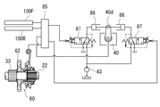
本実施例の油圧モータ41L・41R駆動用油圧回路について説明する。駆動モード切換バルブ44からの一方の油路51aが、一方の油圧モータ41(本実施例では左の油圧モータ41Lとしているが、いずれでもよい)の一方の給排ポートに連通する油路52aに対し、第一デフロックバルブ88aを介して常時(デフロック位置でもデフロック解除位置でも)連通している。該油圧モータ41Lの他方の給排ポートは油路53aを介して第二デフロックバルブ88bに連通しており、該デフロックバルブ88bには、もう一方の油圧モータ41(本実施例では右の油圧モータ41R)の両給排ポートからの油路53b・57が接続されている。油路53bからは駆動モード切換バルブ44への油路51bを分岐させており、油路57からは第一デフロックバルブ88aへの油路52bを分岐させている。   A hydraulic circuit for driving the hydraulic motors 41L and 41R of the present embodiment will be described. One oil passage 51a from the drive mode switching valve 44 is connected to an oil passage 52a communicating with one supply / discharge port of one hydraulic motor 41 (in this embodiment, the left hydraulic motor 41L may be any). In contrast, the first differential lock valve 88a is always in communication (in either the differential lock position or the differential lock release position). The other supply / discharge port of the hydraulic motor 41L communicates with the second differential lock valve 88b through an oil passage 53a. The differential lock valve 88b is connected to the other hydraulic motor 41 (the right hydraulic motor in this embodiment). 41R) oil passages 53b and 57 from both supply and discharge ports are connected. An oil passage 51b to the drive mode switching valve 44 is branched from the oil passage 53b, and an oil passage 52b to the first differential lock valve 88a is branched from the oil passage 57.

両デフロックバルブ88a・88bはソレノイドバルブであり、図外の操作具により同期してそれぞれのデフロック位置とデフロック解除位置とに切り換えられる。両デフロックバルブ88a・88bのソレノイドが解磁状態で図示のデフロック解除位置にある時、第一デフロックバルブ88aは油路51aを分岐し、両油圧モータ41L・41Rの一方の給排ポートに対しそれぞれ油路52a・52bを介して連通させる。一方、第二デフロックバルブ88bは、該油圧モータ41Lからの油路53aを、油路53b・57のうち、油路53bに接続して、油圧モータ41L・41Rの他方の給排ポート同士を接続し、これにより、油圧モータ41L・41Rを油圧ポンプ40に対し並列接続する。従って、油圧ポンプ40からの吐出油が駆動モード切換バルブ44を介してそれぞれの負荷に応じた量で油圧モータ41L・41Rに供給され、両油圧モータ41L・41Rの差動回転が許容される。   Both differential lock valves 88a and 88b are solenoid valves and are switched to a differential lock position and a differential lock release position in synchronization with an operating tool (not shown). When the solenoids of both differential lock valves 88a and 88b are in the illustrated differential lock release position in a demagnetized state, the first differential lock valve 88a branches off the oil passage 51a and is connected to one of the supply / discharge ports of the hydraulic motors 41L and 41R. It connects via oil path 52a * 52b. On the other hand, the second differential lock valve 88b connects the oil passage 53a from the hydraulic motor 41L to the oil passage 53b of the oil passages 53b and 57, and connects the other supply / discharge ports of the hydraulic motors 41L and 41R to each other. As a result, the hydraulic motors 41L and 41R are connected to the hydraulic pump 40 in parallel. Accordingly, the oil discharged from the hydraulic pump 40 is supplied to the hydraulic motors 41L and 41R through the drive mode switching valve 44 in amounts corresponding to the respective loads, and the differential rotation of both hydraulic motors 41L and 41R is allowed.

一方、両デフロックバルブ88a・88bのソレノイドを励磁してデフロック位置にすると、第一ソレノイドバルブ88aは、油圧モータ41Rからの油路52bを、駆動モード切換バルブ44からの油路51aより隔離し、第二ソレノイドバルブ88bは油圧モータ41Lからの油路53aを、油路53b・57のうち、油路57に接続する。これにより、油圧モータ41L・41Rを油圧ポンプ40に対し直列接続し、油圧モータ41L・41Rの差動回転を不可能にする。   On the other hand, when the solenoids of the differential lock valves 88a and 88b are excited to the differential lock position, the first solenoid valve 88a isolates the oil passage 52b from the hydraulic motor 41R from the oil passage 51a from the drive mode switching valve 44, The second solenoid valve 88b connects the oil passage 53a from the hydraulic motor 41L to the oil passage 57 of the oil passages 53b and 57. As a result, the hydraulic motors 41L and 41R are connected in series to the hydraulic pump 40, and the differential rotation of the hydraulic motors 41L and 41R is disabled.

図9に示す第五実施例は、上記第四実施例のバルブ構成・回路構成の簡素化を図ったものであり、前記駆動モード切換バルブ44の油路51aは油圧モータ41Rの油路52bと常時接続し、前記駆動モード切換バルブ44の油路51bは油圧モータ41Lの油路53aと常時接続してある。そして、油圧モータ41Lの油路52aと油圧モータ41Rの油路53bをそれぞれ前記油路51aと前記油路51bの各々に接続するデフロック解除位置と、油圧モータ41Lの油路52aと油圧モータ41Rの油路53bを相互連通させて前記油路51aと前記油路51bをブロックするデフロック位置に切替え可能な単一のデフロックバルブ88cを設ける。該デフロックバルブ88cはソレノイドバルブであり、該ソレノイドが解磁状態でデフロック解除位置にある時、両油圧モータ41L・41Rの一方の給排ポートに通じる油路52a・52bが油路51aと連通する一方、両油圧モータ41L・41Rの他方の給排ポートに通じる油路53a・53bが油路51bと連通する。これにより、油圧モータ41L・41Rを油圧ポンプ40に対し並列接続される。従って、油圧ポンプ40からの吐出油が駆動モード切換バルブ44を介してそれぞれの負荷に応じた量で油圧モータ41L・41Rに供給され、両油圧モータ41L・41Rの差動が許容される。   The fifth embodiment shown in FIG. 9 is intended to simplify the valve configuration and circuit configuration of the fourth embodiment, and the oil passage 51a of the drive mode switching valve 44 is connected to the oil passage 52b of the hydraulic motor 41R. The oil passage 51b of the drive mode switching valve 44 is always connected to the oil passage 53a of the hydraulic motor 41L. A differential lock release position that connects the oil passage 52a of the hydraulic motor 41L and the oil passage 53b of the hydraulic motor 41R to the oil passage 51a and the oil passage 51b, respectively, and the oil passage 52a of the hydraulic motor 41L and the hydraulic motor 41R A single diff-lock valve 88c is provided that can be switched to a diff-lock position that blocks the oil passage 51a and the oil passage 51b by making the oil passage 53b communicate with each other. The differential lock valve 88c is a solenoid valve, and when the solenoid is demagnetized and in the differential lock release position, the oil passages 52a and 52b communicating with one of the supply / discharge ports of the hydraulic motors 41L and 41R communicate with the oil passage 51a. On the other hand, oil passages 53a and 53b communicating with the other supply / discharge ports of both hydraulic motors 41L and 41R communicate with the oil passage 51b. Accordingly, the hydraulic motors 41L and 41R are connected in parallel to the hydraulic pump 40. Accordingly, the oil discharged from the hydraulic pump 40 is supplied to the hydraulic motors 41L and 41R through the drive mode switching valve 44 in an amount corresponding to each load, and the differential between the hydraulic motors 41L and 41R is allowed.

一方、デフロックバルブ88cのソレノイドを励磁してデフロック位置にすると、駆動モード切換バルブ44の油路51aから油圧モータ41Rの油路52b、油路53b、油圧モータ41Lの油路52a、油路53aを経て駆動モード切換バルブ44の油路51bに接続する。これにより、油圧モータ41L・41Rを油圧ポンプ40に対し直列接続されることとなり、油圧モータ41L・41Rの差動を不可能にする。   On the other hand, when the solenoid of the differential lock valve 88c is excited to the differential lock position, the oil passage 51a of the drive mode switching valve 44 to the oil passage 52b, the oil passage 53b of the hydraulic motor 41R, the oil passage 52a of the hydraulic motor 41L, and the oil passage 53a are changed. Then, it connects to the oil passage 51b of the drive mode switching valve 44. As a result, the hydraulic motors 41L and 41R are connected in series to the hydraulic pump 40, and the differential between the hydraulic motors 41L and 41R becomes impossible.

なお、これら第四、五実施例の場合には、並列、直列接続状態で油圧モータ41L・41Rを流れる油量が変化するので、油圧モータ41L・41Rの回転数はデフロック解除位置のときに比べてデフロック位置では大きくなる。この油圧モータの回転数変動は次のようにして防止することができる。   In the case of these fourth and fifth embodiments, the amount of oil flowing through the hydraulic motors 41L and 41R changes in a parallel and series connection state, so the rotational speed of the hydraulic motors 41L and 41R is higher than that at the differential lock release position. It becomes larger at the differential lock position. This fluctuation in the rotational speed of the hydraulic motor can be prevented as follows.

即ち、後車軸駆動装置8が図2に示す第一実施例のように、主変速機構をCVTとしている実施例においては、後車軸ハウジング8aに付設している油圧ポンプ40は前輪駆動用油圧モータ41に作動油を供給するものであるが、この油圧ポンプ40を図示したように可変容積型のものに置き換えて、バルブ80がデフロック位置になった時には該油圧ポンプ40の吐出量を減少させるように制御すればよい。或いは、油圧モータ41L・41Rには可変容積型のものが使用されているので、油圧モータ41L・41Rの容積をバルブ80がデフロック位置になった時に大きくするように制御すればよい。この結果、デフロック解除位置での車軸14の回転数に対して、デフロック位置での車軸14の回転数を略一致させることができる。   That is, in the embodiment in which the rear axle drive device 8 is a CVT as the main transmission mechanism as in the first embodiment shown in FIG. 2, the hydraulic pump 40 attached to the rear axle housing 8a is a front wheel drive hydraulic motor. The hydraulic pump 40 is supplied with hydraulic oil, but the hydraulic pump 40 is replaced with a variable displacement type as shown in the figure so that the discharge amount of the hydraulic pump 40 is reduced when the valve 80 is in the differential lock position. It may be controlled to. Alternatively, since the variable displacement type is used for the hydraulic motors 41L and 41R, the volume of the hydraulic motors 41L and 41R may be controlled to increase when the valve 80 is in the differential lock position. As a result, the rotational speed of the axle 14 at the diff lock position can be made substantially coincident with the rotational speed of the axle 14 at the diff lock release position.

また、後車軸駆動装置8が図3、図4に示す第二・第三実施例のように、主変速機構をHSTとしている場合でも、後者の制御方式を用いることにより対処することができる。   Further, even when the rear axle drive device 8 uses the HST as the main transmission mechanism as in the second and third embodiments shown in FIGS. 3 and 4, the latter control method can be used.

以上の様々なタイプの前車軸駆動装置13のうちの一つと、様々なタイプの後車軸駆動装置8のうちの一つとを選択して組み合わせることにより、四輪駆動運搬車のための多様な伝動構造を提供することができる。   By selecting and combining one of the various types of front axle drive devices 13 and one of the various types of rear axle drive devices 8, a variety of transmissions for a four-wheel drive vehicle Structure can be provided.

次に、本運搬車に適用されるエンジン回転数制御機構について、図10〜図13より説明する。まず、基本的な(図2に示す後車軸駆動装置8に適用されるような)エンジンガバナについては図10に示す如きであり、図2〜図4で開示した如く後車軸駆動装置8のハウジング8a内にて入力軸21上に配設した回転センサ23が、スロットルアクチュエータ81のシリンダ81a内に摺動可能に内装したピストンロッド81bの一端に連係されており、該ピストンロッド81bの他端はエンジン7のスロットルバルブ7cに一体状に設けたスロットルアーム7dに連係されている。具体的には上下中心部にて枢支されたアーム82の回動両端にそれぞれ、ピストンロッド81bの該他端と、該アーム83からのワイヤ等のリンク部材とを連結している。なお、スロットルアーム7dはバネ7eにてスロットルバルブ7cの閉じ側に付勢されている。また、シリンダ81a内にて、ピストンロッド81b上にピストン81cが固設され、該ピストン81cとシリンダ81aの一端との間にバネ81dが介設されている。さらに、シリンダ81aがアクセルペダル4に連係されている。具体的には、上下中心部にて枢支されたアーム82の回動両端にそれぞれ、シリンダ81aと、該スロットルペダル4基端のアーム4aからのワイヤ等のリンク部材とを連結している。   Next, the engine speed control mechanism applied to this transport vehicle will be described with reference to FIGS. First, the basic engine governor (as applied to the rear axle drive device 8 shown in FIG. 2) is as shown in FIG. 10, and the housing of the rear axle drive device 8 as disclosed in FIGS. A rotation sensor 23 disposed on the input shaft 21 in 8a is linked to one end of a piston rod 81b slidably housed in a cylinder 81a of the throttle actuator 81, and the other end of the piston rod 81b is connected to the other end of the piston rod 81b. It is linked to a throttle arm 7d provided integrally with a throttle valve 7c of the engine 7. Specifically, the other end of the piston rod 81b and a link member such as a wire from the arm 83 are connected to both ends of rotation of the arm 82 pivotally supported at the center in the vertical direction. The throttle arm 7d is biased toward the closing side of the throttle valve 7c by a spring 7e. In the cylinder 81a, a piston 81c is fixed on the piston rod 81b, and a spring 81d is interposed between the piston 81c and one end of the cylinder 81a. Further, the cylinder 81a is linked to the accelerator pedal 4. Specifically, the cylinder 81a and a link member such as a wire from the arm 4a at the base end of the throttle pedal 4 are connected to both ends of rotation of the arm 82 pivotally supported at the center in the vertical direction.

図10での位置を基準として説明すると、アクセルペダル4を踏み込むことにより、アーム82の上端が右へ、下端が左へと回動し、これにより、バネ81dの付勢力に抗してシリンダ81bが左に移動する。バネ81dは直ちに復帰してピストン81cを左に押し、ピストンロッド81bを左に移動させる。これにより、アーム83の上端が左に、下端が右に回動して、スロットルアーム7dがバネ7eの付勢力に抗してスロットルバルブ7cの開き側に回動する。こうして、アクセルペダル4の踏み込み量に応じた開度にてアクセルバルブ7cが開く。   Referring to the position in FIG. 10 as a reference, when the accelerator pedal 4 is depressed, the upper end of the arm 82 is rotated to the right and the lower end is rotated to the left, whereby the cylinder 81b resists the biasing force of the spring 81d. Moves to the left. The spring 81d immediately returns to push the piston 81c to the left and move the piston rod 81b to the left. As a result, the upper end of the arm 83 is turned to the left and the lower end is turned to the right, and the throttle arm 7d is turned to the opening side of the throttle valve 7c against the urging force of the spring 7e. Thus, the accelerator valve 7c is opened at an opening corresponding to the depression amount of the accelerator pedal 4.

こうしてアクセルペダル4で設定したスロットルバルブ7cの開度に応じて、入力軸21の回転中は回転センサ23が遠心力で開いている。その入力軸21の回転速度がアクセルペダル4による設定速度よりも落ちると、回転センサ23が閉じて、ピストンロッド81bを左側に押す。これにより、アーム83の上端が左に、下端が右に回動して、スロットルバルブ7cの開き側にスロットルアーム7dが回動し、エンジン回転数を増大させる。   Thus, according to the opening degree of the throttle valve 7c set by the accelerator pedal 4, the rotation sensor 23 is opened by centrifugal force while the input shaft 21 is rotating. When the rotation speed of the input shaft 21 falls below the set speed by the accelerator pedal 4, the rotation sensor 23 closes and pushes the piston rod 81b to the left. As a result, the upper end of the arm 83 rotates to the left and the lower end rotates to the right, and the throttle arm 7d rotates to the opening side of the throttle valve 7c, thereby increasing the engine speed.

なお、図11、図12に示すエンジン回転数制御機構は、図3及び4の如き後車軸駆動装置8を採用した場合のものであり、即ち、主変速としてHSTを設け、その減速比をトルクセンサ60の検出に基づいて制御する構成と組み合わせている。アクセルペダル4は、前進用ペダル4F・後進用ペダル4Rのツインペダルとしており(シーソー型の単一ペダルの各端を前進用・後進用の踏み込み部としてもよい)、スロットルアクチュエータ80のシリンダ80aは、上下中心部を枢支軸として一体に回動するツインアーム82F・82Rの下端が枢結されており、両ツインアーム82F・82Rの上端には、それぞれ各ペダル4F・4Rからのワイヤ等のリンク部材の端部が枢結されている。具体的には各ツインアーム84F・84Rの上端部に長孔82aが形成されていて、各ペダル4F・4Rからのリンク部材の端部を摺動自在に嵌入しており、両ペダル4F・4Rのうち一方が踏み込まれることで、その長孔84a内のリンク部材端部が動いても、もう一方のペダル4Rからのリンク部材の端部はその位置にとどまることができるようになっている。こうして、両ペダル4F・4Rのいずれを踏み込んだ場合にも、その踏み込み量に応じてスロットルバルブ7cの開度が設定される。   The engine speed control mechanism shown in FIGS. 11 and 12 is a case where the rear axle drive device 8 as shown in FIGS. 3 and 4 is employed, that is, an HST is provided as the main transmission, and the reduction ratio is set to the torque. This is combined with a configuration that controls based on the detection of the sensor 60. The accelerator pedal 4 is a twin pedal of a forward pedal 4F and a reverse pedal 4R (each end of a seesaw type single pedal may be used as a forward / backward stepping portion), and a cylinder 80a of the throttle actuator 80 is The lower ends of the twin arms 82F and 82R that rotate integrally with the upper and lower central portions as pivots are pivotally connected. The upper ends of the twin arms 82F and 82R are respectively connected with wires from the pedals 4F and 4R. The end of the link member is pivoted. Specifically, long holes 82a are formed at the upper ends of the twin arms 84F and 84R, and the ends of the link members from the pedals 4F and 4R are slidably fitted. When one of them is stepped on, the end of the link member from the other pedal 4R can remain in that position even if the end of the link member in the elongated hole 84a moves. Thus, regardless of which of the pedals 4F and 4R is depressed, the opening of the throttle valve 7c is set according to the depression amount.

そして、この前進用ペダル4F・後進用ペダル4Rは、そのまま油圧ポンプ40の可動斜板40bの操作具となっており、各ペダル4F・4Rの踏み込み量100F・100Rがポテンショメータ等で検出されて、コントローラ85に入力信号として送信される。可動斜板40bのアクチュエータは電磁弁制御による油圧作動型となっており、これについて図12にて説明する。後車軸ハウジング8aに枢支された可動斜板4b制御用のコントロールアーム40dの回動端に、アクチュエータとしての油圧シリンダ86・86のピストンロッドが両側より連結されており、各油圧シリンダ86にはそれぞれ電磁弁87を介してチャージポンプ43からの圧油が供給される。前述のコントローラに入力された各ペダル4F・4Rの踏み込み量検出値に基づき、電磁弁87・87が制御されて、コントロールアーム40dを回動し、可動斜板40bを踏み込み位置に応じた傾斜角度に設定するのである。さらにその傾斜角度が出力信号としてポテンショメータ等で検出され、フィードバックされて、コントローラ85にてペダル4F・4Rからの踏み込み量検出信号と比較演算されて、偏差が0となるようにコントローラ85より油圧シリンダ86・86に制御信号が発せられる。こうして、可動斜板40bの傾斜角度を、ペダル4F・4Rいずれかの踏み込み量に正確に対応したものにする。   The forward pedal 4F and the reverse pedal 4R serve as operating tools for the movable swash plate 40b of the hydraulic pump 40, and the depression amounts 100F and 100R of the pedals 4F and 4R are detected by a potentiometer or the like. It is transmitted to the controller 85 as an input signal. The actuator of the movable swash plate 40b is hydraulically operated by electromagnetic valve control, which will be described with reference to FIG. Piston rods of hydraulic cylinders 86 and 86 as actuators are connected from both sides to the rotation end of the control arm 40d for controlling the movable swash plate 4b pivotally supported by the rear axle housing 8a. Pressure oil from the charge pump 43 is supplied via the electromagnetic valve 87. The solenoid valves 87 and 87 are controlled on the basis of the depression amount detection values of the pedals 4F and 4R input to the controller, and the control arm 40d is rotated to tilt the movable swash plate 40b according to the depression position. It is set to. Further, the inclination angle is detected by a potentiometer or the like as an output signal, fed back, and compared with a depression amount detection signal from the pedals 4F and 4R by the controller 85, and the hydraulic cylinder from the controller 85 so that the deviation becomes zero. A control signal is issued to 86 and 86. Thus, the inclination angle of the movable swash plate 40b is made to correspond exactly to the depression amount of either the pedal 4F or 4R.

さらに、このように設定した可動斜板40bが、エンジン負荷制御機構を構成するトルクセンサ60でのトルク検出に基づき適正角度に修正される。即ち、出力軸22と大径ギア62との相対回転差が内部のカムボールによって推力に変換されこれをポテンショメータ等でトルクセンサ60のトルク検出量としてコントローラ85にて認識され、所定値以上のトルクが検出されている場合には、可動斜板40bの傾斜角度を中立方向へ減少させてポンプ吐出量を減少させるべく、電磁弁87・87を制御する。なお、図12に図示のトルクセンサ60は、図4に示す場合のものであり、図3に示す実施例に適用されるように、入力軸21の第一部21a・第二部21bとの間に介設するものとして、両者21a・21b間の相対回転差を推力に変換するものとしてもよい。水力にもよい。   Furthermore, the movable swash plate 40b set in this way is corrected to an appropriate angle based on torque detection by the torque sensor 60 constituting the engine load control mechanism. That is, the relative rotational difference between the output shaft 22 and the large-diameter gear 62 is converted into a thrust by an internal cam ball, and this is recognized by the controller 85 as a torque detection amount of the torque sensor 60 by a potentiometer or the like, and a torque greater than a predetermined value is detected. If it is detected, the electromagnetic valves 87 and 87 are controlled so as to reduce the pump discharge amount by decreasing the inclination angle of the movable swash plate 40b in the neutral direction. The torque sensor 60 shown in FIG. 12 is the one shown in FIG. 4, and is applied to the first part 21a and the second part 21b of the input shaft 21 as applied to the embodiment shown in FIG. As what is interposed, it is good also as what converts the relative rotation difference between both 21a * 21b into thrust. Good for hydropower.

このHSTによる負荷制御は、トルクセンサの検出ではなく、HSTの油圧検出によるものとしてもよい。図13は、HSTの油圧検出に基づくエンジン負荷制御機構を開示している。前・後進ペダル4F・4R、回転センサ23、スロットルバルブ7c、及びスロットルアクチュエータ81で構成されるエンジン回転数制御機構の構成は、図11に示したものと同様である。油圧ポンプ40・油圧モータ45間の一対の油路それぞれの油圧を検出するセンサとして、油圧スライダ90が設けられている。油圧スライダ90は、スプール状で軸芯方向に移動可能であり、両端より中立位置にバネ96・96にて付勢されていて、その各端部は、各プランジャ95F・95Rに押接している。油圧ポンプ40の可動斜板40bは、斜板アクチュエータたる複動式油圧シリンダ94のピストン94aと操作連係されていて、方向切換バルブ92からの一対の油路がピストン94a両側の油室のそれぞれに連通している。ピストン94aから延びるフィードバックアーム94bが方向切換バルブ92外周に配したスリーブ92aと機械的に連係され、これにより、方向切換バルブ92がスリーブ92a内を移動して中立位置より前進または後進位置に切替えられピストン94aが移動するとスリーブ92aを同方向へ移動させて相対的に原位置に戻して中立位置に制御される。   The load control by the HST may be based on the detection of the hydraulic pressure of the HST instead of the detection of the torque sensor. FIG. 13 discloses an engine load control mechanism based on HST oil pressure detection. The configuration of the engine speed control mechanism including the forward / reverse pedals 4F and 4R, the rotation sensor 23, the throttle valve 7c, and the throttle actuator 81 is the same as that shown in FIG. A hydraulic slider 90 is provided as a sensor that detects the hydraulic pressure of each of the pair of oil passages between the hydraulic pump 40 and the hydraulic motor 45. The hydraulic slider 90 has a spool shape and is movable in the axial direction. The hydraulic slider 90 is biased by springs 96 and 96 to neutral positions from both ends, and each end thereof is pressed against each plunger 95F and 95R. . The movable swash plate 40b of the hydraulic pump 40 is operatively linked to a piston 94a of a double-acting hydraulic cylinder 94, which is a swash plate actuator, and a pair of oil passages from the direction switching valve 92 are provided in oil chambers on both sides of the piston 94a. Communicate. A feedback arm 94b extending from the piston 94a is mechanically linked to a sleeve 92a disposed on the outer periphery of the direction switching valve 92, whereby the direction switching valve 92 moves in the sleeve 92a and is switched from the neutral position to the forward or reverse position. When the piston 94a is moved, the sleeve 92a is moved in the same direction to relatively return to the original position and controlled to the neutral position.

プランジャ95Fは、そのプランジャ油室95aが、油圧ポンプ・モータ40・45間の閉回路を構成する一対の油路のうち、前進時に高圧側となる油路に連通し、プランジャ95Rのプランジャ油室95aは、後進時に高圧側となる油路に連通している。各油路を流れる油圧は絞りを経て該プランジャ油室95a内に導入され、バネ96・96の付勢力を上回ると各プランジャ95F・95Rが押し出されて、油圧スライダ90を反対側に押動する。   The plunger 95F has a plunger oil chamber 95a that communicates with an oil passage that is on the high-pressure side of a pair of oil passages constituting a closed circuit between the hydraulic pump / motors 40 and 45, and a plunger oil chamber of the plunger 95R. 95a communicates with an oil passage that is on the high pressure side during reverse travel. The oil pressure flowing through each oil passage is introduced into the plunger oil chamber 95a through a throttle, and when the urging force of the springs 96 and 96 is exceeded, the plungers 95F and 95R are pushed out to push the hydraulic slider 90 to the opposite side. .

方向切換バルブ92の操作部材としてのリンクロッド91の途中部に係合ピン91aを設けており、該油圧スライダ90の軸芯方向の長孔90a内に該係合ピン91aを摺動可能に嵌入している。該リンクロッド91は該油圧スライダ90を通過して、その先端を揺動アーム93一端の受け部93a内にて、設定負荷相当の付勢力を有するバネ93b・93bにより両側より挟持している。該揺動アーム93は、その途中部に枢支点を有し、該受け部93aとは反対側の端部に、前進ペダル4F・後進ペダル4Rからのリンク部材(ロッド或いはワイヤ等)の各一端が接続されている。   An engagement pin 91a is provided in the middle of the link rod 91 as an operation member of the direction switching valve 92, and the engagement pin 91a is slidably fitted into the long hole 90a in the axial direction of the hydraulic slider 90. doing. The link rod 91 passes through the hydraulic slider 90, and its tip is clamped from both sides by a spring 93b and 93b having a biasing force corresponding to a set load in a receiving portion 93a at one end of the swing arm 93. The swing arm 93 has a pivot point in the middle thereof, and at each end opposite to the receiving portion 93a, each end of a link member (rod or wire, etc.) from the forward pedal 4F and the reverse pedal 4R. Is connected.

前進ペダル4Fには揺動アーム4Fa、後進ペダル4Rには揺動アーム4Raがそれぞれ固設されている。該揺動アーム4Faは、その上下途中部が前進ペダル4Fの基端枢支点となっていて、その下端がスロットルアクチュエータ81のアーム82Fへのリンク部材との接続点に、そして、その上端が、前記揺動アーム93へのリンク部材との接続点になっている。一方、該揺動アーム4Raは、その上端が後進ペダル4Rの基端枢支点となっていて、その下端部にスロットルアクチュエータ81のアーム82Rへのリンク部材との接続点と、揺動アーム93へのリンク部材との接続点とを設けている。従って、前進ペダル4Fを踏むか、後進ペダル4Rを踏むかで、アーム93の揺動方向が反対になる。図13によれば、前進ペダル4Fを踏み込むと、アーム4Faの上端が左方に回動するので、揺動アーム93の受け部93aは右に回動する。一方、後進ペダル4Rを踏み込むと、アーム4Raの下端が右方に回動するので、揺動アーム93の受け部93aは左に回動する。   A swing arm 4Fa is fixed to the forward pedal 4F, and a swing arm 4Ra is fixed to the reverse pedal 4R. The swing arm 4Fa has a base end pivot point of the forward pedal 4F in the upper and lower middle part thereof, a lower end thereof at a connection point with a link member to the arm 82F of the throttle actuator 81, and an upper end thereof. It is a connection point with the link member to the swing arm 93. On the other hand, the upper end of the swing arm 4Ra is a base end pivot point of the reverse pedal 4R, the lower end of the swing arm 4Ra is connected to the link member to the arm 82R of the throttle actuator 81, and the swing arm 93 is connected. And a connection point with the link member. Therefore, the swinging direction of the arm 93 is reversed depending on whether the forward pedal 4F is depressed or the reverse pedal 4R is depressed. According to FIG. 13, when the forward pedal 4F is depressed, the upper end of the arm 4Fa rotates to the left, so that the receiving portion 93a of the swing arm 93 rotates to the right. On the other hand, when the reverse pedal 4R is depressed, the lower end of the arm 4Ra rotates to the right, so that the receiving portion 93a of the swing arm 93 rotates to the left.

ここで、図13での位置関係をもとに、前進ペダル4Fを踏んだ場合を想定すると、揺動アーム93が紙面時計回りに揺動して左側のバネ93bを通じてリンクロッド91を右方へ移動させる。また、油圧スライダ90の長孔90a内を右に係合ピン91aが移動して、該長孔90aの右端に当接する。これにより、方向切換バルブ92を中立位置から紙面左側の前進位置へ切り換え、油圧シリンダ94のピストン94aを移動し、可動斜板40bを中立位置から前進方向へ傾動させた後、方向切換バルブ92はピストン94aからのフィードバックを受けて中立位置に復帰する。この結果、可動斜板40bの傾動位置が保持される。   Here, based on the positional relationship in FIG. 13, assuming that the forward pedal 4F is stepped on, the swing arm 93 swings clockwise in the drawing and the link rod 91 is moved to the right through the left spring 93b. Move. Further, the engagement pin 91a moves to the right in the long hole 90a of the hydraulic slider 90 and comes into contact with the right end of the long hole 90a. As a result, the direction switching valve 92 is switched from the neutral position to the forward position on the left side of the drawing, the piston 94a of the hydraulic cylinder 94 is moved, and the movable swash plate 40b is tilted from the neutral position to the forward direction. In response to feedback from the piston 94a, it returns to the neutral position. As a result, the tilting position of the movable swash plate 40b is maintained.

油圧ポンプ40からの圧油を受けて駆動される油圧モータ45が前進駆動用に作動している間は、プランジャ95Fのプランジャ油室95aに連通する油路が高圧側になるが、この高圧側油路の油圧が絞りを経てプランジャ95Fのプランジャ室95a内に導入され、バネ96の付勢力以上の圧力に達するとプランジャ95Fは油圧スライダ90を左に押動する。この時、係合ピン91aが長孔90aの右端にあるため、係合ピン91aが油圧スライダ90に押されて左方に移動することとなり、従って、リンクロッド91は、左方に押し返され、方向切換バルブ92は、中立位置から紙面右側の後進位置に切り換わり、可動斜板40bを中立位置の方向へ動かしてその傾斜角を小さくして、油圧ポンプ40の吐出量を低減し、プランジャ95Fのプランジャ室95a内に導入される圧油がバネ96の付勢力以下の圧力になるまで継続される。これにより、HSTにかかる負荷を自動的に軽減する。後進ペダル9Rの踏み込み時にも同様の負荷制御がなされる。   While the hydraulic motor 45 driven by the pressure oil from the hydraulic pump 40 is operating for forward drive, the oil passage communicating with the plunger oil chamber 95a of the plunger 95F is on the high pressure side. When the oil pressure in the oil passage is introduced into the plunger chamber 95a of the plunger 95F through a throttle and reaches a pressure equal to or greater than the urging force of the spring 96, the plunger 95F pushes the hydraulic slider 90 to the left. At this time, since the engaging pin 91a is located at the right end of the long hole 90a, the engaging pin 91a is pushed by the hydraulic slider 90 and moves to the left. Therefore, the link rod 91 is pushed back to the left. The direction switching valve 92 switches from the neutral position to the reverse position on the right side of the page, moves the movable swash plate 40b in the direction of the neutral position to reduce the inclination angle, and reduces the discharge amount of the hydraulic pump 40. The pressure oil introduced into the 95F plunger chamber 95a is continued until the pressure becomes equal to or less than the biasing force of the spring 96. As a result, the load on the HST is automatically reduced. Similar load control is performed when the reverse pedal 9R is depressed.

このように、油圧スライダ90は、高圧側となっている油路の油圧が設定値以上になった時に、前進・後進ペダル4F・4Rいずれかの踏み込み量に応じて設定した油圧ポンプ40の吐出量を低減させるのである。   As described above, the hydraulic slider 90 discharges the hydraulic pump 40 set according to the depression amount of either the forward / reverse pedal 4F or 4R when the hydraulic pressure of the oil passage on the high pressure side becomes equal to or higher than the set value. The amount is reduced.

本発明の後車軸駆動装置8の第一実施例と前車軸駆動装置13の第一実施例とを採用する四輪駆動運搬車の側面略図である。1 is a schematic side view of a four-wheel drive vehicle employing a first embodiment of a rear axle drive device 8 and a first embodiment of a front axle drive device 13 of the present invention. 後車軸駆動装置8の第一実施例のスケルトン図である。2 is a skeleton diagram of a first embodiment of a rear axle drive device 8; FIG. 後車軸駆動装置8の第二実施例のスケルトン図である。FIG. 5 is a skeleton diagram of a second embodiment of the rear axle drive device 8. 後車軸駆動装置8の第三実施例のスケルトン図である。FIG. 6 is a skeleton diagram of a third embodiment of the rear axle drive device 8. 前車軸駆動装置13の第一実施例のスケルトン図である。1 is a skeleton diagram of a first embodiment of a front axle drive device 13. FIG. 前車軸駆動装置13の第二実施例のスケルトン図である。FIG. 6 is a skeleton diagram of a second embodiment of the front axle drive device 13. 前車軸駆動装置13の第三実施例のスケルトン図である。It is a skeleton figure of the 3rd example of front axle drive unit 13. 前車軸駆動装置13の第四実施例のスケルトン図である。It is a skeleton figure of 4th Example of the front axle drive device 13. FIG. 前車軸駆動装置13の第五実施例のスケルトン図である。It is a skeleton figure of 5th Example of the front axle drive device 13. FIG. 基本的なエンジンガバナの構造略図である。1 is a schematic structural diagram of a basic engine governor. 後車軸駆動装置8の主変速機構をHSTとした場合に採用される、前進・後進ペダル4F・4Rを用いたエンジンガバナの構造略図である。6 is a schematic diagram of the structure of an engine governor using forward / reverse pedals 4F and 4R, which is employed when the main transmission mechanism of the rear axle drive device 8 is HST. 後車軸駆動装置8の主変速機構をHSTとした場合の、可動斜板40bの制御機構の油圧回路図である。FIG. 6 is a hydraulic circuit diagram of a control mechanism for the movable swash plate 40b when the main transmission mechanism of the rear axle drive device 8 is HST. 後車軸駆動装置8の主変速機構をHSTとした場合の、エンジンガバナと、HSTの油圧検出によるHSTの負荷制御ガバナの構造略図である。4 is a schematic diagram of the structure of an engine governor and an HST load control governor based on HST oil pressure detection when the main transmission mechanism of the rear axle drive device 8 is HST.

符号の説明Explanation of symbols

4 アクセルペダル
4F 前進ペダル
4R 後進ペダル
7 エンジン(原動機)
8 後車軸駆動装置(第一車軸駆動装置)
8a 後車軸ハウジング(第一車軸支持ハウジング)
9 後車軸(第一車軸)
10 後輪
13 前車軸駆動装置(第二車軸駆動装置)
13a 前車軸ハウジング(第二車軸支持ハウジング)
14 前車軸(第二車軸)
15 前輪
20 CVT(ベルト式無段変速装置)
40 油圧ポンプ
41 (前輪駆動用)油圧モータ
44 駆動モード切換バルブ
45 (後輪駆動用)油圧モータ
71 クラッチ
73 リミティッドスリップ機構
4 Accelerator pedal 4F Forward pedal 4R Reverse pedal 7 Engine (motor)
8 Rear axle drive device (first axle drive device)
8a Rear axle housing (first axle support housing)
9 Rear axle (first axle)
10 Rear wheel 13 Front axle drive device (second axle drive device)
13a Front axle housing (second axle support housing)
14 Front axle (second axle)
15 front wheel 20 CVT (belt type continuously variable transmission)
40 Hydraulic Pump 41 (For Front Wheel Drive) Hydraulic Motor 44 Drive Mode Switching Valve 45 (For Rear Wheel Drive) Hydraulic Motor 71 Clutch 73 Limited Slip Mechanism

Claims (15)

原動機を挟んで、第一車軸を駆動する第一車軸駆動装置と、第二車軸を駆動する第二車軸駆動装置とを機体前後に配設しており、該第二車軸駆動装置は、該第二車軸駆動用に油圧モータを備えており、該第一車軸駆動装置は、前記第一車軸駆動用に正逆転切換機能を有する変速機構を備えて前記原動機に駆動連結しているとともに、該第二車軸駆動装置の油圧モータに作動油を供給するための油圧ポンプを備えていることを特徴とする四輪駆動車両。   A first axle driving device for driving the first axle and a second axle driving device for driving the second axle are disposed in front of and behind the fuselage with the prime mover interposed therebetween. A hydraulic motor is provided for two-axle drive, and the first axle drive device is provided with a speed change mechanism having a forward / reverse switching function for driving the first axle, and is drivingly connected to the prime mover. A four-wheel drive vehicle comprising a hydraulic pump for supplying hydraulic oil to a hydraulic motor of a two-axle drive device. 前記第一車軸駆動装置において、前記油圧ポンプは、該第一車軸駆動装置のハウジング内に設けた伝動軸をポンプ軸として、該ハウジングに取り付けられていることを特徴とする請求項1記載の四輪駆動車両。   4. The four axles according to claim 1, wherein in the first axle driving device, the hydraulic pump is attached to the housing by using a transmission shaft provided in the housing of the first axle driving device as a pump shaft. Wheel drive vehicle. 前記伝動軸は、前記第一車軸駆動装置の変速機構の出力軸により駆動されていることを特徴とする請求項2記載の四輪駆動車両。   The four-wheel drive vehicle according to claim 2, wherein the transmission shaft is driven by an output shaft of a speed change mechanism of the first axle drive device. 前記第一車軸駆動装置において、前記変速機構は、該第一車軸駆動装置のハウジング外に設けた上手側の第一変速機構と、該ハウジング内に設けた下手側の第二変速機構とよりなることを特徴とする請求項1記載の四輪駆動車両。   In the first axle drive device, the speed change mechanism includes an upper first speed change mechanism provided outside the housing of the first axle drive device and a lower second speed change mechanism provided in the housing. The four-wheel drive vehicle according to claim 1. 前記第一変速機構をCVTとし、前記第二変速機構が前記の正逆切換機能を有するものとし、前記油圧ポンプは、該第二変速機構の出力軸をポンプ軸として設けられていることを特徴とする請求項4記載の四輪駆動車両。   The first transmission mechanism is a CVT, the second transmission mechanism has the forward / reverse switching function, and the hydraulic pump is provided with the output shaft of the second transmission mechanism as a pump shaft. The four-wheel drive vehicle according to claim 4. 前記第一車軸駆動装置において、前記変速機構は、油圧ポンプと第一車軸駆動用の油圧モータとを組み合わせてなるHSTを備えており、該HSTの油圧ポンプを前記の第二車軸駆動装置の油圧モータへの作動油供給用の油圧ポンプとして兼用することを特徴とする請求項1記載の四輪駆動車両。   In the first axle drive device, the speed change mechanism includes an HST in which a hydraulic pump and a hydraulic motor for driving the first axle are combined, and the hydraulic pump of the HST is used as the hydraulic pressure of the second axle drive device. The four-wheel drive vehicle according to claim 1, wherein the vehicle is also used as a hydraulic pump for supplying hydraulic oil to the motor. 前記油圧ポンプを可変容積型とし、前記の変速機構における正逆転切換機能を該油圧ポンプの吐出方向の切換により現出することを特徴とする請求項6記載の四輪駆動車両。   7. The four-wheel drive vehicle according to claim 6, wherein the hydraulic pump is of a variable displacement type, and the forward / reverse switching function in the transmission mechanism appears by switching the discharge direction of the hydraulic pump. 前記油圧ポンプは、前記原動機の出力軸をポンプ軸として設けられていることを特徴とする請求項6記載の四輪駆動車両。   The four-wheel drive vehicle according to claim 6, wherein the hydraulic pump is provided with an output shaft of the prime mover as a pump shaft. 前記変速機構は、前記第一車軸駆動装置のハウジング外に設けた前記HSTと、その下手側であって、該ハウジング内に設けた有段の第二変速機構とよりなるものとし、前記第一車軸駆動用の油圧モータのモータ軸を、該第二変速機構の入力軸としていることを特徴とする請求項6記載の四輪駆動車両。   The transmission mechanism includes the HST provided outside the housing of the first axle drive device, and a stepped second transmission mechanism provided on the lower side of the HST and inside the housing. The four-wheel drive vehicle according to claim 6, wherein a motor shaft of a hydraulic motor for driving the axle is used as an input shaft of the second transmission mechanism. 前記第一車軸駆動用の油圧モータを可変容積型とし、前記第一車軸を支持する前記第一車軸駆動装置のハウジング内に収納したことを特徴とする請求項6記載の四輪駆動車両。   The four-wheel drive vehicle according to claim 6, wherein the hydraulic motor for driving the first axle is a variable displacement type and is housed in a housing of the first axle drive device that supports the first axle. 前記第二車軸駆動装置において、前記第二車軸を左右一対とし、該左右一対の第二車軸と前記油圧モータとの間に差動機構を設けていることを特徴とする請求項1記載の四輪駆動車両。   4. The four-axle drive device according to claim 1, wherein the second axle drive device comprises a pair of left and right second axles, and a differential mechanism is provided between the pair of left and right second axles and the hydraulic motor. Wheel drive vehicle. 前記第二車軸駆動装置において、前記第二車軸を左右一対とし、該左右一対の第二車軸各別駆動用に前記の油圧モータを一対備えていることを特徴とする請求項1記載の四輪駆動車両。 2. The four-wheel vehicle according to claim 1, wherein the second axle drive device includes a pair of left and right second axles, and a pair of the hydraulic motors for driving each of the second pair of left and right axles. Driving vehicle. 前記第二車軸駆動装置において、前記一対の油圧モータのモータ軸同士を、差動制限機構を介して機械式に接続することを特徴とする請求項12記載の四輪駆動車両。   The four-wheel drive vehicle according to claim 12, wherein in the second axle drive device, the motor shafts of the pair of hydraulic motors are mechanically connected via a differential limiting mechanism. 前記第二車軸駆動装置において、前記一対の油圧モータを、前記第一車軸駆動装置における油圧ポンプに対し並列接続して前記第二車軸の差動回転を許容するとともに、両油圧モータを直列接続に切替え可能に構成することを特徴とする請求項12記載の四輪駆動車両。 In the second axle drive device, the pair of hydraulic motors are connected in parallel to the hydraulic pump in the first axle drive device to allow differential rotation of the second axle, and both hydraulic motors are connected in series. The four-wheel drive vehicle according to claim 12, wherein the four-wheel drive vehicle is configured to be switchable. 前記第二車軸駆動装置において、前記油圧モータと前記第二車軸との間に、該第二車軸側から該油圧モータへの伝動を防止し、該油圧モータから該第二車軸への伝動のみを可能とするクラッチを介設していることを特徴とする請求項1記載の四輪駆動車両。   In the second axle drive device, transmission from the second axle side to the hydraulic motor is prevented between the hydraulic motor and the second axle, and only transmission from the hydraulic motor to the second axle is performed. 4. The four-wheel drive vehicle according to claim 1, further comprising an enabling clutch.
JP2004120847A 2004-04-15 2004-04-15 Four-wheel drive vehicle Pending JP2005297923A (en)

Priority Applications (4)

Application Number Priority Date Filing Date Title
JP2004120847A JP2005297923A (en) 2004-04-15 2004-04-15 Four-wheel drive vehicle
US11/104,457 US20050230171A1 (en) 2004-04-15 2005-04-13 Four-wheel drive vehicle
EP05008220A EP1586479B1 (en) 2004-04-15 2005-04-14 Four-wheel drive vehicle
DE602005008299T DE602005008299D1 (en) 2004-04-15 2005-04-14 Four-wheel drive vehicle

Applications Claiming Priority (1)

Application Number Priority Date Filing Date Title
JP2004120847A JP2005297923A (en) 2004-04-15 2004-04-15 Four-wheel drive vehicle

Publications (1)

Publication Number Publication Date
JP2005297923A true JP2005297923A (en) 2005-10-27

Family

ID=34935203

Family Applications (1)

Application Number Title Priority Date Filing Date
JP2004120847A Pending JP2005297923A (en) 2004-04-15 2004-04-15 Four-wheel drive vehicle

Country Status (4)

Country Link
US (1) US20050230171A1 (en)
EP (1) EP1586479B1 (en)
JP (1) JP2005297923A (en)
DE (1) DE602005008299D1 (en)

Cited By (2)

* Cited by examiner, † Cited by third party
Publication number Priority date Publication date Assignee Title
JP2008137436A (en) * 2006-11-30 2008-06-19 Kubota Corp Tractor PTO structure
WO2025142809A1 (en) * 2023-12-25 2025-07-03 住友重機械工業株式会社 Master machine

Families Citing this family (16)

* Cited by examiner, † Cited by third party
Publication number Priority date Publication date Assignee Title
EP1808324B1 (en) * 2006-01-16 2010-03-17 Kanzaki Kokyukoki Mfg. Co., Ltd. Hydrostatic transaxle
DE102007053320A1 (en) * 2007-11-08 2009-05-14 Agco Gmbh Transmission synchronization method and apparatus for at least two transmissions
DE102007058535A1 (en) * 2007-12-06 2009-06-10 Deere & Company, Moline Drive system of a work vehicle
US8002073B2 (en) * 2008-04-22 2011-08-23 Kanzaki Kokyukoki Mfg. Co., Ltd. Hydraulic drive working vehicle
ITPD20090025A1 (en) * 2009-02-11 2010-08-12 Faresin Ind S P A MIXING WAGON FOR THE PREPARATION AND DISTRIBUTION OF FOOD IN ZOOTECHNIC AREA, PARTICULARLY SUITABLE FOR HIGH SPEED OF TRANSFER
JP4873058B2 (en) * 2009-09-28 2012-02-08 マツダ株式会社 Automatic transmission for vehicles
TWI444550B (en) * 2010-06-08 2014-07-11 Ind Tech Res Inst Control method and system for hydraulic control device of stepless transmission of compound power system
CN102358163B (en) * 2011-08-09 2014-03-26 吉林大学 Hydraulic driving system for hub motor
US9242544B2 (en) * 2011-09-23 2016-01-26 Kanzaki Kokyukoki Mfg. Co., Ltd. Vehicle with electric transaxle
DE102012010946A1 (en) * 2012-06-04 2013-12-05 Claas Selbstfahrende Erntemaschinen Gmbh Hydrostatic drive unit of a vehicle
JP5705928B2 (en) * 2013-08-08 2015-04-22 株式会社小松製作所 Wheel loader
FR3010006B1 (en) * 2013-09-03 2017-05-12 Poclain Hydraulics Ind HYDRAULIC ASSISTED VEHICLE COMPRISING AN IMPROVED DIFFERENTIAL STRUCTURE ON THE AXLE
JP2015054578A (en) * 2013-09-11 2015-03-23 株式会社 神崎高級工機製作所 Travel transmission gear for work vehicle
GB2531767A (en) * 2014-10-29 2016-05-04 Bamford Excavators Ltd Working Machine
US11535208B2 (en) * 2018-03-05 2022-12-27 Kanzaki Kokyukoki Mfg. Co., Ltd. Hydraulic transaxle
CN108725195A (en) * 2018-06-22 2018-11-02 长沙桑铼特农业机械设备有限公司 A kind of fluid power system and tractor

Citations (6)

* Cited by examiner, † Cited by third party
Publication number Priority date Publication date Assignee Title
JPH05104968A (en) * 1991-10-16 1993-04-27 Ntn Corp Driving force transmitting device for vehicle
JPH05246259A (en) * 1992-03-06 1993-09-24 Nippondenso Co Ltd Four wheel drive vehicle
JPH09309352A (en) * 1996-05-24 1997-12-02 Nissan Motor Co Ltd Four-wheel drive vehicle
JPH10181362A (en) * 1996-12-24 1998-07-07 Kanzaki Kokyukoki Mfg Co Ltd Four-wheel drive mechanism of traveling vehicle
JP2001180319A (en) * 1999-12-21 2001-07-03 Kanzaki Kokyukoki Mfg Co Ltd Multi-wheel drive vehicle
JP2003003880A (en) * 2002-04-17 2003-01-08 Mazda Motor Corp Drive system for vehicle

Family Cites Families (22)

* Cited by examiner, † Cited by third party
Publication number Priority date Publication date Assignee Title
CH393935A (en) * 1960-04-02 1965-06-15 Maschf Augsburg Nuernberg Ag All-wheel drive for haulers
GB1071661A (en) * 1963-07-03 1967-06-14 Lucas Industries Ltd Attachments for use with wheeled vehicles
GB1165217A (en) * 1965-10-22 1969-09-24 Int Harvester Co Four Wheel Drive for Vehicles
DE2039668A1 (en) * 1970-08-10 1972-02-17 Kloeckner Humboldt Deutz Ag Vehicle, in particular motor vehicle for agricultural use
DE2052084A1 (en) * 1970-10-23 1972-04-27 Zahnradfabrik Friedrichshafen Ag, 7990 Friedrichshafen Vehicle axle in the form of a housing
DE3216821A1 (en) * 1982-05-05 1983-11-10 Zahnradfabrik Friedrichshafen Ag, 7990 Friedrichshafen HYDROSTATIC DRIVE FOR VEHICLES
AT384283B (en) * 1984-08-30 1987-10-27 Steyr Daimler Puch Ag DRIVE ARRANGEMENT FOR MOTOR VEHICLES WITH TWO DRIVE AXLES
JPH0747850A (en) * 1993-08-05 1995-02-21 Honda Motor Co Ltd Vehicle power transmission device
DE59301564D1 (en) * 1993-10-29 1996-03-14 Ec Eng & Consult Spezialmasch Method for hydrostatically driving a vehicle
US5427195A (en) * 1994-05-04 1995-06-27 Int. Silvatech Ltd. Hydraulic drive and steering systems for a vehicle
US5607027A (en) * 1995-04-28 1997-03-04 Anser, Inc. Hydraulic drive system for a vehicle
EP1745973A1 (en) * 1997-07-22 2007-01-24 Kanzaki Kokyukoki Mfg. Co., Ltd. Driving system for a working vehicle
US6540633B1 (en) * 1998-09-25 2003-04-01 Tuff Torq Corporation Transmission for speed changing and steering of a vehicle
FR2789352B1 (en) * 1999-02-05 2001-04-27 Poclain Hydraulics Ind DEVICE FOR TRANSMITTING A MOBILE MACHINE HAVING AT LEAST TWO IN-LINE MOTOR MOVING DEVICES
WO2000071459A1 (en) * 1999-05-21 2000-11-30 Tcm Corporation Fork lift with traverse system
US6536845B2 (en) * 2000-02-14 2003-03-25 Multiquip, Inc. All wheel drive power buggy
EP1442240A1 (en) * 2001-10-12 2004-08-04 Clark Equipment Company Operation of wheeled work machine
JP2003136988A (en) * 2001-10-30 2003-05-14 Kanzaki Kokyukoki Mfg Co Ltd Traveling transmission mechanism for vehicle
US6845837B2 (en) * 2002-10-15 2005-01-25 Kanzaki Kokyukoki Mfg. Co., Ltd. Hydraulic transaxle apparatus for a four-wheel driving vehicle and four-wheel driving vehicle using the apparatus
JP4131816B2 (en) * 2002-12-27 2008-08-13 株式会社 神崎高級工機製作所 Driving device for traveling vehicle
US6926111B1 (en) * 2003-05-09 2005-08-09 Koji Irikura Vehicle having front and rear steerable driven wheels
US7204779B2 (en) * 2003-09-26 2007-04-17 Koji Irikura Hydraulic steering transaxle and hydraulic driving vehicle

Patent Citations (6)

* Cited by examiner, † Cited by third party
Publication number Priority date Publication date Assignee Title
JPH05104968A (en) * 1991-10-16 1993-04-27 Ntn Corp Driving force transmitting device for vehicle
JPH05246259A (en) * 1992-03-06 1993-09-24 Nippondenso Co Ltd Four wheel drive vehicle
JPH09309352A (en) * 1996-05-24 1997-12-02 Nissan Motor Co Ltd Four-wheel drive vehicle
JPH10181362A (en) * 1996-12-24 1998-07-07 Kanzaki Kokyukoki Mfg Co Ltd Four-wheel drive mechanism of traveling vehicle
JP2001180319A (en) * 1999-12-21 2001-07-03 Kanzaki Kokyukoki Mfg Co Ltd Multi-wheel drive vehicle
JP2003003880A (en) * 2002-04-17 2003-01-08 Mazda Motor Corp Drive system for vehicle

Cited By (2)

* Cited by examiner, † Cited by third party
Publication number Priority date Publication date Assignee Title
JP2008137436A (en) * 2006-11-30 2008-06-19 Kubota Corp Tractor PTO structure
WO2025142809A1 (en) * 2023-12-25 2025-07-03 住友重機械工業株式会社 Master machine

Also Published As

Publication number Publication date
EP1586479A2 (en) 2005-10-19
DE602005008299D1 (en) 2008-09-04
US20050230171A1 (en) 2005-10-20
EP1586479B1 (en) 2008-07-23
EP1586479A3 (en) 2006-07-19

Similar Documents

Publication Publication Date Title
JP2005297923A (en) Four-wheel drive vehicle
KR101240817B1 (en) Speed change power transmission device
US7404341B2 (en) Transmission system for tractor
US5937697A (en) Power take-off assembly for tractors
US6044720A (en) Drive transmission assembly for working vehicles
KR20010050864A (en) Power transmission for vehicle
JP2002087086A (en) Power take-off device for work vehicle
KR100373584B1 (en) Steering apparatus of working vehicle
JP2009078699A (en) Driving transmission structure of work vehicle
JP2009078785A (en) Driving transmission structure of work vehicle
JP2008045723A (en) Hydraulic continuously variable transmission
JP4104148B2 (en) Tractor transmission structure
JP4104149B2 (en) Tractor PTO transmission structure
JP4233498B2 (en) Tractor operation structure
JP3583064B2 (en) Agricultural work equipment steering device
JP2002144901A (en) Transmission for tractor
JP3013780B2 (en) Operating device and switching operating device for vehicle power transmission device
JP3583063B2 (en) Agricultural work equipment steering device
JP4194832B2 (en) Vehicle frame structure
JP2007203972A (en) Power take-out device for traveling transmission mechanism
JP4017512B2 (en) Brake mechanism
JP4375776B2 (en) Vehicle frame structure
JP2006017142A (en) Power vehicle transmission
JP3659897B2 (en) Steering device for agricultural machinery
JP3652268B2 (en) Spool valve operating device

Legal Events

Date Code Title Description
A621 Written request for application examination

Free format text: JAPANESE INTERMEDIATE CODE: A621

Effective date: 20061219

A977 Report on retrieval

Free format text: JAPANESE INTERMEDIATE CODE: A971007

Effective date: 20090612

A131 Notification of reasons for refusal

Free format text: JAPANESE INTERMEDIATE CODE: A131

Effective date: 20090616

A521 Written amendment

Free format text: JAPANESE INTERMEDIATE CODE: A523

Effective date: 20090723

A131 Notification of reasons for refusal

Free format text: JAPANESE INTERMEDIATE CODE: A131

Effective date: 20091117

A02 Decision of refusal

Free format text: JAPANESE INTERMEDIATE CODE: A02

Effective date: 20100413