JP2005297746A - Underwater scooter - Google Patents

Underwater scooter Download PDF

Info

Publication number
JP2005297746A
JP2005297746A JP2004116160A JP2004116160A JP2005297746A JP 2005297746 A JP2005297746 A JP 2005297746A JP 2004116160 A JP2004116160 A JP 2004116160A JP 2004116160 A JP2004116160 A JP 2004116160A JP 2005297746 A JP2005297746 A JP 2005297746A
Authority
JP
Japan
Prior art keywords
water
watertight container
underwater scooter
air
engine
Prior art date
Legal status (The legal status is an assumption and is not a legal conclusion. Google has not performed a legal analysis and makes no representation as to the accuracy of the status listed.)
Withdrawn
Application number
JP2004116160A
Other languages
Japanese (ja)
Inventor
Hiroshi Sueshige
洋 末繁
Masayuki Osumi
雅之 大角
Yoshihiro Iijima
良洋 飯嶋
Keiji Iino
啓司 飯野
Hiroaki Hasebe
博昭 長谷部
Current Assignee (The listed assignees may be inaccurate. Google has not performed a legal analysis and makes no representation or warranty as to the accuracy of the list.)
Honda Motor Co Ltd
Original Assignee
Honda Motor Co Ltd
Priority date (The priority date is an assumption and is not a legal conclusion. Google has not performed a legal analysis and makes no representation as to the accuracy of the date listed.)
Filing date
Publication date
Application filed by Honda Motor Co Ltd filed Critical Honda Motor Co Ltd
Priority to JP2004116160A priority Critical patent/JP2005297746A/en
Priority to US11/102,163 priority patent/US7011035B2/en
Publication of JP2005297746A publication Critical patent/JP2005297746A/en
Withdrawn legal-status Critical Current

Links

Images

Landscapes

  • Automatic Cycles, And Cycles In General (AREA)

Abstract

<P>PROBLEM TO BE SOLVED: To provide an underwater motor scooter preventing overheat by improving heat radiating property of a driving source for driving a propeller and improving comfortableness by warming the body of an operator. <P>SOLUTION: This scooter is provided with a watertight container 14 arranged in front of the operator (OP), an engine stored in the watertight container 14, an intake port 66a opened toward the front in the watertight container 14, a drain port 66b opened toward a rear side in the watertight container 14, and a water path 66 for communicating the intake port 66a with the drain port 66b by passing the vicinity of the engine. The heat radiating property of the engine E is improved by performing a heat exchange between water flowing into the water path 66 and air within the watertight container 14. The body of the operator is warmed by discharging water (warm water) warmed by the heat exchange from the drain port toward the operator. <P>COPYRIGHT: (C)2006,JPO&NCIPI

Description

この発明は、水上または水中を航行する水中スクータに関する。   The present invention relates to an underwater scooter that sails on water or underwater.

従来、操縦者(ダイバー)に操縦されて水上または水中を航行する水中スクータが提案されている。この種の水中スクータにあっては、一般に、内燃機関あるいは電動モータを駆動源としてプロペラを駆動することによって推進力を得る。そして、操縦者が把持すべきグリップを備え、かかるグリップを把持した操縦者を牽引することにより、その進行を補助するように構成している(例えば特許文献1参照)。
特公平4−17832号公報
2. Description of the Related Art Conventionally, an underwater scooter that is operated by a pilot (diver) and navigates on or under water has been proposed. In this type of underwater scooter, generally, propulsion is obtained by driving a propeller using an internal combustion engine or an electric motor as a drive source. And it is comprised so that a pilot may be equipped with the grip which should be hold | gripped, and the advance is assisted by towing the pilot who hold | gripped this grip (for example, refer patent document 1).
Japanese Patent Publication No. 4-17832

水中スクータの駆動源は、通常、密閉された空間内に収容される。このため、放熱性が低く、オーバーヒートを招き易いという不具合があった。   The drive source of the underwater scooter is usually housed in a sealed space. For this reason, there existed a malfunction that heat dissipation was low and overheating was easy to be caused.

また、従来の牽引型の水中スクータは、プロペラが操縦者よりも前方に配置されることから、プロペラから噴出された水流によって操縦者の体が冷やされ、快適性が低下するという不具合があった。   In addition, the conventional tow-type underwater scooter has a problem that since the propeller is disposed in front of the operator, the body of the operator is cooled by the water flow ejected from the propeller and the comfort is lowered. .

従って、この発明の目的は上記した課題を解決することにあり、駆動源の放熱性を向上させてオーバーヒートを防止すると共に、操縦者の体を温めて快適性を向上させるようにした水中スクータを提供することにある。   Accordingly, an object of the present invention is to solve the above-mentioned problems, and an underwater scooter that improves the heat dissipation of the drive source to prevent overheating and warms the operator's body to improve comfort. It is to provide.

上記した課題を解決するために、請求項1にあっては、操縦者に操縦されて水上または水中を航行する水中スクータにおいて、前記操縦者の前方に配置された水密容器と、前記水密容器に収容された駆動源と、前記駆動源に駆動されて前記水中スクータを推進させるプロペラと、前記水密容器において前方に向けて開口された取水口と、前記水密容器において後方に向けて開口された排水口と、前記駆動源の近傍を通過して前記取水口と前記排水口を連通する水路とを備えるように構成した。   In order to solve the above-described problem, in claim 1, in an underwater scooter that is operated by a pilot and sails on or under water, a watertight container disposed in front of the pilot, and the watertight container A housed drive source, a propeller driven by the drive source to propel the underwater scooter, a water intake opening opened forward in the watertight container, and a waste water opened backward in the watertight container An opening and a water channel that passes through the vicinity of the drive source and communicates the intake port and the drain port are provided.

また、請求項2にあっては、前記水路が、前記水密容器内の空気と前記水路を流れる流体との間の熱交換を促進する受熱手段を備えるように構成した。   According to a second aspect of the present invention, the water channel includes heat receiving means for promoting heat exchange between the air in the watertight container and the fluid flowing through the water channel.

また、請求項3にあっては、前記受熱手段が、前記水路の周囲に設けられたフィンからなるように構成した。   According to a third aspect of the present invention, the heat receiving means is constituted by fins provided around the water channel.

請求項1に係る水中スクータにあっては、操縦者の前方に配置された水密容器と、水密容器に収容された駆動源と、駆動源に駆動されて前記水中スクータを推進させるプロペラと、水密容器において前方に向けて開口された取水口と、水密容器において後方に向けて開口された排水口と、駆動源の近傍を通過して取水口と排水口を連通する水路とを備えるように構成したので、水路を流れる流体と水密容器内の空気との間で熱交換がなされるため、駆動源の放熱性が向上し、よってオーバーヒートを防止することができる。また、かかる熱交換によって暖められた流体が、後方に向けて開口された排水口から操縦者に向かって排出される(操縦者に供給される)ため、操縦者の体を温めることができ、よって快適性を向上させることができる。   In the underwater scooter according to claim 1, a watertight container disposed in front of the operator, a drive source accommodated in the watertight container, a propeller driven by the drive source to propel the underwater scooter, and a watertight A water intake opening that opens forward in the container, a water discharge opening that opens backward in the watertight container, and a water channel that passes through the vicinity of the drive source and communicates the water intake and the water discharge opening. Therefore, heat exchange is performed between the fluid flowing in the water channel and the air in the watertight container, so that the heat dissipation of the drive source is improved and thus overheating can be prevented. In addition, since the fluid warmed by such heat exchange is discharged toward the pilot from the drain opening opened rearward (supplied to the pilot), the pilot's body can be warmed, Therefore, comfort can be improved.

また、請求項2に係る水中スクータにあっては、水路が、水密容器内の空気と水路を流れる流体との間の熱交換を促進する受熱手段を備えるように構成したので、駆動源の放熱性をより向上させることができるため、オーバーヒートを一層効果的に防止することができる。また、操縦者に供給される流体の温度をより効率的に上昇させることができることから、操縦者の保温性が向上し、よって快適性を一層向上させることができる。   In the underwater scooter according to claim 2, since the water channel includes heat receiving means for promoting heat exchange between the air in the watertight container and the fluid flowing through the water channel, the heat radiation of the drive source is performed. Therefore, overheating can be more effectively prevented. In addition, since the temperature of the fluid supplied to the operator can be increased more efficiently, the heat retaining property of the operator is improved, and thus the comfort can be further improved.

また、請求項3に係る水中スクータにあっては、受熱手段が、水路の周囲に設けられたフィンからなるように構成したので、上記した効果を簡素な構成で得ることができる。   In the underwater scooter according to the third aspect, since the heat receiving means is constituted by fins provided around the water channel, the above effect can be obtained with a simple configuration.

以下、添付図面に即してこの発明に係る水中スクータを実施するための最良の形態について説明する。   The best mode for carrying out the underwater scooter according to the present invention will be described below with reference to the accompanying drawings.

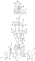
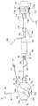
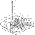
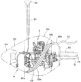
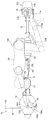
図1は、この実施例に係る水中スクータの平面図である。また、図2は、図1に示す水中スクータの左側面図であり、図3は、図1に示す水中スクータの正面図である。   FIG. 1 is a plan view of an underwater scooter according to this embodiment. 2 is a left side view of the underwater scooter shown in FIG. 1, and FIG. 3 is a front view of the underwater scooter shown in FIG.

図1から図3において、符号10は水中スクータを示す。先ず、水中スクータ10の構成について概説すると、水中スクータ10は、円筒状に形成されてその長手方向が水中スクータ10の進行方向に対して平行となるように配置されたメインフレーム12と、メインフレーム12において進行方向前方に配置された卵型の水密(気密)容器14と、水密容器14の内部に収容された内燃機関(駆動源。図1から図3で図示せず。以下「エンジン」という)と、メインフレーム12において進行方向後方に配置され、エンジンで駆動されて回転して水中スクータ10を推進させるプロペラ16と、メインフレーム12の内部に挿通されてエンジンの出力をプロペラ16に伝達するドライブシャフト(図1から図3で図示せず)と、水密容器14の付近に配置されて水中スクータ10の航行深度の調整を行う深度調整機構18と、プロペラ16の付近に配置されて水中スクータ10の進行方向の調整を行う操舵機構20と、メインフレーム12において水密容器14とプロペラ16の間に配置された第1のエアタンク22と第2のエアタンク24を備える。   1 to 3, reference numeral 10 denotes an underwater scooter. First, the configuration of the underwater scooter 10 will be outlined. The underwater scooter 10 is formed in a cylindrical shape, and the main frame 12 is disposed so that its longitudinal direction is parallel to the traveling direction of the underwater scooter 10. 12, an egg-shaped watertight (airtight) container 14 disposed in front of the traveling direction, and an internal combustion engine (drive source not shown in FIGS. 1 to 3) housed in the watertight container 14. Hereinafter referred to as “engine”. ) And a propeller 16 that is disposed behind the main frame 12 in the traveling direction and is driven by the engine to rotate to propel the underwater scooter 10, and is inserted into the main frame 12 to transmit the output of the engine to the propeller 16. The drive shaft (not shown in FIGS. 1 to 3) and the depth of adjustment of the underwater scooter 10 disposed near the watertight container 14 are adjusted. A depth adjusting mechanism 18 for performing the operation, a steering mechanism 20 for adjusting the traveling direction of the underwater scooter 10 disposed in the vicinity of the propeller 16, and a first air tank disposed between the watertight container 14 and the propeller 16 in the main frame 12. 22 and a second air tank 24.

次いで、上記した各構成について詳説する。   Next, each of the above-described configurations will be described in detail.

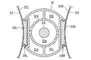
図4は、図1のIV−IV線拡大断面図である。図示の如く、メインフレーム12の内部は区画壁によって分割され、5つの通路が形成される。各通路は、メインフレーム12の先端から後端まで連続する1つの空間として形成される。5つの通路のうち、中心に位置する円筒状の第1の通路12aには、前記したドライブシャフト(符号26で示す)が挿通される。これに対し、第1の通路12aの外周を分割して形成された第2から第5の通路12b,12c,12d,12eは、後述の如く、空気や排出ガスの流路となる。   4 is an enlarged sectional view taken along line IV-IV in FIG. As illustrated, the interior of the main frame 12 is divided by a partition wall to form five passages. Each passage is formed as one space continuous from the front end to the rear end of the main frame 12. Of the five passages, the above-described drive shaft (indicated by reference numeral 26) is inserted into a cylindrical first passage 12a located at the center. On the other hand, the second to fifth passages 12b, 12c, 12d, and 12e formed by dividing the outer periphery of the first passage 12a serve as air and exhaust gas passages as will be described later.

メインフレーム12の両側面には、断面視において略Cの字状(あるいはその左右対称の断面形状)を呈する溝部28L,28Rが形成される。図2に示すように、溝部28L(およびその裏面に位置する溝部28R)は、メインフレーム12の長手方向(進行方向)に所定の長さを有するように形成される。   On both side surfaces of the main frame 12, grooves 28L and 28R having a substantially C-shape (or a symmetric cross-sectional shape thereof) in a sectional view are formed. As shown in FIG. 2, the groove portion 28 </ b> L (and the groove portion 28 </ b> R located on the back surface thereof) is formed to have a predetermined length in the longitudinal direction (traveling direction) of the main frame 12.

図4の説明を続けると、左右の溝部28L,28Rには、それぞれ断面視において略Hの字状を呈するスライダ30L,30Rがスライド自在に嵌められる。即ち、スライダ30L,30Rは、溝部28L,28Rの上端と下端に形成された突起をレールとして、スライド自在に構成される。   If the explanation of FIG. 4 is continued, sliders 30L and 30R each having a substantially H shape in a sectional view are slidably fitted in the left and right grooves 28L and 28R, respectively. That is, the sliders 30L and 30R are configured to be slidable with the protrusions formed on the upper and lower ends of the grooves 28L and 28R as rails.

スライダ30L,30Rには、それぞれベルト32L,32Rが設けられる。前記した第1のエアタンク22と第2のエアタンク24は、ベルト32L,32Rを介してそれぞれスライダ30L,30Rに装着される。これにより、第1のエアタンク22と第2のエアタンク24は、メインフレーム12の長手方向(即ち、水中スクータ10の進行方向)にスライド自在に装着される。   Belts 32L and 32R are provided on the sliders 30L and 30R, respectively. The first air tank 22 and the second air tank 24 described above are mounted on the sliders 30L and 30R via belts 32L and 32R, respectively. Thus, the first air tank 22 and the second air tank 24 are slidably mounted in the longitudinal direction of the main frame 12 (that is, the traveling direction of the underwater scooter 10).

図1から図3の説明に戻ると、第1のエアタンク22は、バルブ36を介してレギュレータ38に接続される。レギュレータ38は、ホース40を介してメインフレーム12の内部(具体的には第2の通路12b)に接続される。一方、第2のエアタンク24は、バルブ42を介してレギュレータ44に接続される。レギュレータ44は、ホース46を介してメインフレーム12の内部(具体的には、第3の通路12c)に接続される。尚、第1および第2のエアタンク22,24の容積は、例えば12リットル程度であり、その内部には空気が高圧(例えば200気圧程度)に圧縮されて封入される。   Returning to the description of FIG. 1 to FIG. 3, the first air tank 22 is connected to a regulator 38 via a valve 36. The regulator 38 is connected to the inside of the main frame 12 (specifically, the second passage 12b) via the hose 40. On the other hand, the second air tank 24 is connected to a regulator 44 via a valve 42. The regulator 44 is connected to the inside of the main frame 12 (specifically, the third passage 12c) via the hose 46. The volumes of the first and second air tanks 22 and 24 are, for example, about 12 liters, and the air is compressed and sealed in the interior at a high pressure (for example, about 200 atmospheres).

第1のエアタンク22に封入された空気は、レギュレータ38で所定の圧力(例えば10気圧程度)まで減圧された後、ホース40を介してメインフレーム12の第2の通路12bに供給される。一方、第2のエアタンク24に封入された空気は、レギュレータ44で前記した所定の圧力(10気圧程度)まで減圧された後、ホース46を介してメインフレーム12の第3の通路12cに供給される。   The air sealed in the first air tank 22 is depressurized to a predetermined pressure (for example, about 10 atm) by the regulator 38 and then supplied to the second passage 12 b of the main frame 12 through the hose 40. On the other hand, the air sealed in the second air tank 24 is reduced to the predetermined pressure (about 10 atmospheres) by the regulator 44 and then supplied to the third passage 12 c of the main frame 12 through the hose 46. The

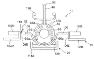
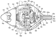
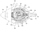
図5は、図1のV−V線拡大断面図である。また、図6は、図2のVI−VI線拡大断面図である。   FIG. 5 is an enlarged sectional view taken along line VV in FIG. 6 is an enlarged sectional view taken along line VI-VI in FIG.

図5および図6に示すように、水密容器14は、進行方向前方からバンパー14a、燃料タンク14bおよびエンジン収容部14cの3つの部材から構成される。   As shown in FIGS. 5 and 6, the watertight container 14 is composed of three members, a bumper 14 a, a fuel tank 14 b, and an engine housing portion 14 c from the front in the traveling direction.

エンジン収容部14cには、エンジンEが収容される。エンジンEは、例えば排気量30cc程度の単気筒火花点火式ガソリンエンジンである。また、エンジン収容部14cの上部には、上方へと突出するシュノーケル48が設けられ、かかるシュノーケル48を介してエンジン収容部14cの内部と外部(大気)とが連通される。   The engine E is accommodated in the engine accommodating portion 14c. The engine E is, for example, a single cylinder spark ignition type gasoline engine having a displacement of about 30 cc. A snorkel 48 that protrudes upward is provided on the upper portion of the engine housing portion 14c, and the inside and the outside (atmosphere) of the engine housing portion 14c communicate with each other via the snorkel 48.

エンジン収容部14cの前方には、ボルト50によって燃料タンク14bが取り付けられ、燃料タンク14bには、エンジンEに供給されるべきガソリン燃料が貯留される。また、燃料タンク14bの前面には給油口52が穿設され、給油口52は、キャップ54によって封止される。   A fuel tank 14b is attached by a bolt 50 in front of the engine housing portion 14c, and gasoline fuel to be supplied to the engine E is stored in the fuel tank 14b. Further, a fuel filler port 52 is formed in the front surface of the fuel tank 14 b, and the fuel filler port 52 is sealed with a cap 54.

燃料タンク14bの前方には、前記キャップ54を被覆するようにバンパー14aが取り付けられる。バンパー14aは、水中スクータ10が外部と衝突したときに変形して衝撃を緩和できるように、他の部材よりも硬度の小さい材料で形成される。また、バンパー14aは、燃料タンク14bへのガソリン燃料の供給を容易に行うことができるように、工具を使用することなく着脱自在とされる。   A bumper 14a is attached to the front of the fuel tank 14b so as to cover the cap 54. The bumper 14a is formed of a material having a hardness lower than that of other members so that the bumper 14a can be deformed and relieve the impact when the underwater scooter 10 collides with the outside. The bumper 14a is detachable without using a tool so that gasoline fuel can be easily supplied to the fuel tank 14b.

また、エンジン収容部14cの後方には、ボルト56によって接続部材60が取り付けられる。接続部材60は、メインフレーム12の直径と略同径の内径を有する円筒部60aを備える。   A connection member 60 is attached to the rear of the engine housing portion 14c with a bolt 56. The connection member 60 includes a cylindrical portion 60 a having an inner diameter that is substantially the same as the diameter of the main frame 12.

図7は、図5のVII−VII線拡大断面図である。図7に示すように、メインフレーム12の先端付近には、ナット62が収容される。図5から図7に示すように、接続部材60の円筒部60aにメインフレーム12の先端を挿入し、ちょうボルト64をナット62に螺合させることにより、メインフレーム12の前方に接続部材60を介して水密容器14が取り付けられる。尚、ナット62は、図7に示す如く周囲を区画壁で囲われ、その回転が抑止される。   7 is an enlarged sectional view taken along line VII-VII in FIG. As shown in FIG. 7, a nut 62 is accommodated near the tip of the main frame 12. As shown in FIGS. 5 to 7, the end of the main frame 12 is inserted into the cylindrical portion 60 a of the connection member 60, and the butterfly bolt 64 is screwed into the nut 62 so that the connection member 60 is placed in front of the main frame 12. The watertight container 14 is attached via The nut 62 is surrounded by a partition wall as shown in FIG. 7, and its rotation is suppressed.

図5および図6の説明に戻ると、メインフレーム12の第2の通路12bは、接続部材60に形成された連通路60b(図6に示す)を介し、水密容器14内に配置されたレギュレータ68に接続される。また、第3の通路12cは、接続部材60の内部に形成された連通路(図示せず)と水密容器14内に設けられた流路70を介し、水密容器14の外部へと連続するホース72に接続される。ホース72の先端には、レギュレータ74が接続され、レギュレータ74には、さらにマウスピース76(いずれも図1および図2に示す)が接続される。   Returning to the description of FIGS. 5 and 6, the second passage 12 b of the main frame 12 is a regulator disposed in the watertight container 14 via a communication passage 60 b (shown in FIG. 6) formed in the connection member 60. 68. Further, the third passage 12c is a hose that continues to the outside of the watertight container 14 via a communication passage (not shown) formed inside the connection member 60 and a flow path 70 provided in the watertight container 14. 72. A regulator 74 is connected to the tip of the hose 72, and a mouthpiece 76 (both shown in FIGS. 1 and 2) is further connected to the regulator 74.

また、メインフレーム12の第4の通路12dは、接続部材60に形成された連通路60cを介してエンジンEの排気管78に接続される。尚、図示は省略するが、第5の通路12eは、接続部材60に形成された連通路を介して水密容器14の内部と連通される。   Further, the fourth passage 12 d of the main frame 12 is connected to the exhaust pipe 78 of the engine E through a communication passage 60 c formed in the connection member 60. Although not shown, the fifth passage 12e communicates with the inside of the watertight container 14 through a communication passage formed in the connection member 60.

エンジンEは、図示しない吸気管を備える。吸気管の入口付近にはエアフィルタが設けられると共に、その下流にはスロットルボディ(いずれも図示せず)が配置される。スロットルボディにはスロットルバルブが収容されると共に、その上流側にはキャブレタ・アシー(いずれも図示せず)が設けられる。キャブレタ・アシーには燃料管80(図5に示す)が接続される。燃料管80は燃料タンク14bの内部に連通されると共に、その先端には燃料ポンプ82が接続される。   The engine E includes an intake pipe (not shown). An air filter is provided in the vicinity of the inlet of the intake pipe, and a throttle body (both not shown) is disposed downstream thereof. A throttle valve is accommodated in the throttle body, and a carburetor assembly (both not shown) is provided upstream of the throttle valve. A fuel pipe 80 (shown in FIG. 5) is connected to the carburetor assembly. The fuel pipe 80 communicates with the inside of the fuel tank 14b, and a fuel pump 82 is connected to the tip thereof.

また、エンジンEのクランクシャフトES(図5に示す)の一端には、遠心クラッチ84が接続される。遠心クラッチ84の出力側は減速機構86に接続され、減速機構86の出力側はドライブシャフト26の前端に接続される。尚、水中スクータ10にはエンジンEの回転数を調節する図示しないスロットル装置が設けられ、遠心クラッチ84は、エンジンEの回転数が上昇させられたときにその動力を伝達する。   A centrifugal clutch 84 is connected to one end of the crankshaft ES (shown in FIG. 5) of the engine E. The output side of the centrifugal clutch 84 is connected to the speed reduction mechanism 86, and the output side of the speed reduction mechanism 86 is connected to the front end of the drive shaft 26. The underwater scooter 10 is provided with a throttle device (not shown) for adjusting the rotational speed of the engine E, and the centrifugal clutch 84 transmits the power when the rotational speed of the engine E is increased.

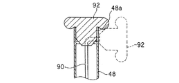
一方、クランクシャフトESの他端には、リコイルスタータ88が取り付けられる。リコイルスタータ88のスタータロープ90は、シュノーケル48の内部に挿通されると共に、その先端にはスタータグリップ92が設けられる。スタータグリップ92は、シュノーケル48の上端に着脱自在に構成される。具体的には、スタータグリップ92は、シュノーケル48の上端にその開口部を水密に封止するように装着されると共に、前記上端から取り外し自在に構成される。即ち、エンジンEを始動させる際はシュノーケル48の上端からスタータグリップ92を取り外し、スタータロープ90を引き出す。エンジンEを始動した後は、シュノーケル48から水が浸入するのを防止すべく、シュノーケル48の上端にスタータグリップ92を取り付けてその開口部を封止する。   On the other hand, a recoil starter 88 is attached to the other end of the crankshaft ES. The starter rope 90 of the recoil starter 88 is inserted into the snorkel 48 and a starter grip 92 is provided at the tip thereof. The starter grip 92 is configured to be detachable from the upper end of the snorkel 48. Specifically, the starter grip 92 is attached to the upper end of the snorkel 48 so as to seal the opening in a watertight manner, and is configured to be removable from the upper end. That is, when starting the engine E, the starter grip 92 is removed from the upper end of the snorkel 48 and the starter rope 90 is pulled out. After starting the engine E, in order to prevent water from entering from the snorkel 48, a starter grip 92 is attached to the upper end of the snorkel 48 and its opening is sealed.

図8は、シュノーケル48の上端付近の拡大図であり、図9は図8のIX−IX線断面図である。図8および図9に示す如く、シュノーケル48の上端には、取り外したスタータグリップ92(図9に破線で示す)を係止すべき切り欠き部48aが設けられる。   8 is an enlarged view near the upper end of the snorkel 48, and FIG. 9 is a cross-sectional view taken along the line IX-IX in FIG. As shown in FIGS. 8 and 9, the upper end of the snorkel 48 is provided with a notch 48 a to which the removed starter grip 92 (shown by a broken line in FIG. 9) is to be locked.

ここで、第1のエアタンク22から所定の圧力に減圧されてメインフレーム12の第2の通路12bに供給された空気は、連通路60bを介してレギュレータ68に供給されると共に、レギュレータ68で水密容器14の内圧まで減圧された後、水密容器14の内部(具体的にはエンジン収容部14c)に供給される。   Here, the air that has been decompressed to a predetermined pressure from the first air tank 22 and is supplied to the second passage 12b of the main frame 12 is supplied to the regulator 68 through the communication passage 60b, and is also watertight by the regulator 68. After the pressure is reduced to the internal pressure of the container 14, the pressure is supplied to the inside of the watertight container 14 (specifically, the engine housing portion 14 c).

水密容器14に供給された空気は、エアフィルタを介して吸気管に吸入される。キャブレタ・アシーは、吸入された空気にガソリン燃料を噴射して混合気を生成する。生成された混合気は、エンジンEの燃焼室(図示せず)に吸入されて燃焼させられる。混合気の燃焼によって生じた排出ガスは、排気管78および連通路60cを介してメインフレーム12の第4の通路12dに流入する。   The air supplied to the watertight container 14 is sucked into the intake pipe through the air filter. The carburetor assembly injects gasoline fuel into the inhaled air to generate an air-fuel mixture. The generated air-fuel mixture is sucked into a combustion chamber (not shown) of the engine E and burned. The exhaust gas generated by the combustion of the air-fuel mixture flows into the fourth passage 12d of the main frame 12 through the exhaust pipe 78 and the communication passage 60c.

一方、第2のエアタンク24から所定の圧力に減圧されてメインフレーム12の第3の通路12cに供給された空気は、前記した連通路と流路70、さらにはホース72を介してレギュレータ74に供給される。レギュレータ74は、図示しないダイヤフラムなどを備え、マウスピース76を咥えた操縦者(ダイバー)によって吸気動作が行われたとき、周囲の水圧まで減圧した空気を操縦者に供給する。   On the other hand, the air that has been depressurized from the second air tank 24 to a predetermined pressure and supplied to the third passage 12c of the main frame 12 is supplied to the regulator 74 via the communication passage and the passage 70, and further through the hose 72. Supplied. The regulator 74 includes a diaphragm or the like (not shown), and when the intake operation is performed by the operator (diver) holding the mouthpiece 76, the regulator 74 supplies the operator with the air reduced to the surrounding water pressure.

このように、水中スクータ10にあっては、メインフレーム12に第1のエアタンク22を取り付け、第1のエアタンク22に封入された空気をエンジンEの燃焼用の空気として供給するようにした。また、メインフレーム12に第2のエアタンク24を取り付け、第2のエアタンク24に封入された空気を操縦者の呼吸用の空気として供給するようにした。   As described above, in the underwater scooter 10, the first air tank 22 is attached to the main frame 12, and the air sealed in the first air tank 22 is supplied as combustion air for the engine E. In addition, a second air tank 24 is attached to the main frame 12, and the air sealed in the second air tank 24 is supplied as air for breathing of the operator.

図5および図6の説明を続けると、エンジン収容部14cの内部には、水路66が設けられる。水路66は、図1から図3に破線で示す如く、複数本、具体的には4本形成される。   Continuing the description of FIGS. 5 and 6, a water channel 66 is provided inside the engine housing portion 14 c. As shown by broken lines in FIGS. 1 to 3, a plurality of water channels 66, specifically, four water channels 66 are formed.

図10は水路66を示す側面図であり、図11は水路66を示す平面図である。   FIG. 10 is a side view showing the water channel 66, and FIG. 11 is a plan view showing the water channel 66.

図10および図11に示すように、水密容器14の底面前方には、進行方向前方に向かって開口された取水口66aが複数個、具体的には2個形成される。また、水密容器14の上面後方には、進行方向後方に向かって開口された排水口66bが複数個、具体的には4個形成される。   As shown in FIGS. 10 and 11, a plurality of water intake ports 66 a opened to the front in the traveling direction are formed in front of the bottom surface of the watertight container 14, specifically, two. In addition, a plurality of, specifically four, drain ports 66b opened rearward in the traveling direction are formed at the rear of the upper surface of the watertight container 14.

水路66は、エンジンEあるいはその排気管78の近傍を通過すると共に、前記した取水口66aと排水口66bを連通するように形成される。水路66は、詳しくは取水口66aから排水口66bに向かう途中で2股に分岐された2組の管路からなり、よって2個の取水口66aと4個の排水口66bとが連通される。   The water channel 66 is formed so as to pass through the vicinity of the engine E or its exhaust pipe 78 and to connect the intake port 66a and the drain port 66b. Specifically, the water channel 66 is composed of two sets of pipes branched in two on the way from the water intake port 66a to the water discharge port 66b, and thus the two water intake ports 66a and the four water discharge ports 66b communicate with each other. .

また、各水路66の周囲には、フィン66c(受熱手段)が設けられる。フィン66cは、図示の如く、各水路66の周囲に複数枚形成されると共に、各フィン66cは、取水口66aの付近から排水口66bの付近にかけて連続して形成される。   Further, around each water channel 66, fins 66c (heat receiving means) are provided. As shown in the drawing, a plurality of fins 66c are formed around each water channel 66, and each fin 66c is formed continuously from the vicinity of the water intake port 66a to the vicinity of the drain port 66b.

水中スクータ10が航行(前進)すると、進行方向前方に向けて開口された取水口66aから水路66に水(流体)が流入する。水路66に流入した水は、そこで水密容器14内の空気(エンジンEの発熱によって昇温された空気)と熱交換がなされて暖められた後(別言すれば、水密容器14内の空気を冷却した後)、進行方向後方に向けて開口された排水口66bから水中スクータ10の後方へと排出される。尚、水路66にはフィン66cが設けられる(水密容器14内の空気との接触面積が増大される)ことから、水路66を流れる水と水密容器14内の空気との間の熱交換が促進され、よって水密容器14内の空気がより効果的に冷却される(排水口66bから排出される水(温水)がより効率的に昇温される)。   When the underwater scooter 10 sails (advances), water (fluid) flows into the water channel 66 from a water intake 66a that opens forward in the traveling direction. The water that has flowed into the water channel 66 is heated by heat exchange with the air in the watertight container 14 (air heated by the heat generated by the engine E) (in other words, the air in the watertight container 14 is After cooling), the water is discharged to the rear of the underwater scooter 10 from the drain port 66b that is opened rearward in the traveling direction. In addition, since the fin 66c is provided in the water channel 66 (the contact area with the air in the watertight container 14 is increased), heat exchange between the water flowing in the water channel 66 and the air in the watertight container 14 is promoted. Thus, the air in the watertight container 14 is cooled more effectively (the water (hot water) discharged from the drain port 66b is heated more efficiently).

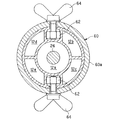
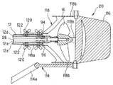
図12は、図1のXII−XII線拡大断面図である。   12 is an enlarged sectional view taken along line XII-XII in FIG.

図12に示す如く、第1の通路12aに挿通されたドライブシャフト26の後端には、プロペラ16が取り付けられる。即ち、水中スクータ10は、メインフレーム12の前方に配置されたエンジンEの出力を前記した遠心クラッチ84、減速機構86およびメインフレーム12の内部に挿通されたドライブシャフト26を介してメインフレーム12の後方に配置されたプロペラ16に伝達し、よってプロペラ16を駆動して水上または水中を航行する。   As shown in FIG. 12, the propeller 16 is attached to the rear end of the drive shaft 26 inserted through the first passage 12a. That is, the underwater scooter 10 receives the output of the engine E disposed in front of the main frame 12 through the centrifugal clutch 84, the speed reduction mechanism 86, and the drive shaft 26 inserted into the main frame 12 so that the main frame 12 It is transmitted to the propeller 16 disposed at the rear, and thus the propeller 16 is driven to sail on or under water.

また、メインフレーム12の第4の通路12dの後端には、第1のワンウェイチェックバルブ94が配置される。第1のワンウェイチェックバルブ94は、排出ガスが第4の通路12dに流入してその内圧が所定の圧力を上回ったときに開弁し、第4の通路12dを外部(水中)に連通させる。即ち、エンジンEから排出された排出ガスは、排気管78、連通路60c、メインフレーム12の第4の通路12dおよび第1のワンウェイチェックバルブ94を介して水中スクータ10の後方(外部)へと排出される。   A first one-way check valve 94 is disposed at the rear end of the fourth passage 12d of the main frame 12. The first one-way check valve 94 opens when the exhaust gas flows into the fourth passage 12d and the internal pressure thereof exceeds a predetermined pressure, and communicates the fourth passage 12d to the outside (underwater). That is, the exhaust gas exhausted from the engine E passes to the rear (outside) of the underwater scooter 10 via the exhaust pipe 78, the communication passage 60c, the fourth passage 12d of the main frame 12, and the first one-way check valve 94. Discharged.

さらに、メインフレーム12の第5の通路12eの後端には、第2のワンウェイチェックバルブ96が配置される。第2のワンウェイチェックバルブ96は、第5の通路12eの内圧(別言すれば、第5の通路12eに連通された水密容器14の内圧)が所定の圧力を上回ったときに開弁し、第5の通路12eを外部(水中)に連通させる。即ち、エンジンEの発熱などによって水密容器14の内圧が上昇すると、水密容器14内の空気が、接続部材60に形成された連通路、メインフレーム12の第5の通路12eおよび第2のワンウェイチェックバルブ96を介して水中スクータ10の後方(外部)へと排出され、よって水密容器14の内圧が調整(減圧)される。   Further, a second one-way check valve 96 is disposed at the rear end of the fifth passage 12 e of the main frame 12. The second one-way check valve 96 opens when the internal pressure of the fifth passage 12e (in other words, the internal pressure of the watertight container 14 communicated with the fifth passage 12e) exceeds a predetermined pressure, The fifth passage 12e is communicated with the outside (underwater). That is, when the internal pressure of the watertight container 14 rises due to heat generated by the engine E, etc., the air in the watertight container 14 flows into the communication path formed in the connecting member 60, the fifth path 12e of the main frame 12, and the second one-way check. The water is discharged to the rear (outside) of the underwater scooter 10 through the valve 96, and the internal pressure of the watertight container 14 is adjusted (depressurized).

上記の如く、メインフレーム12に形成された第1の通路12aは、ドライブシャフト26の挿通路となる。また、第2の通路12bは、エンジンEに供給されるべき燃焼用空気の流路となり、第3の通路12cは、操縦者に供給されるべき呼吸用空気の流路となる。さらに、第4の通路12dは、エンジンEから排出された排出ガスの流路となり、第5の通路12eは、水密容器14内の空気を外部に排出してその内圧を調整するための連通路となる。   As described above, the first passage 12 a formed in the main frame 12 serves as an insertion passage for the drive shaft 26. The second passage 12b is a flow path for combustion air to be supplied to the engine E, and the third passage 12c is a flow path for breathing air to be supplied to the operator. Further, the fourth passage 12d is a flow path for exhaust gas discharged from the engine E, and the fifth passage 12e is a communication passage for discharging the air in the watertight container 14 to the outside and adjusting its internal pressure. It becomes.

尚、図示は省略するが、第2の通路12bと第3の通路12cは、メインフレーム12の後端において封止される。第2の通路12bと第3の通路12cをメインフレーム12の後端で封止するのは、メインフレーム12の前端から後端に空気を充満させ、メインフレーム12全体に均等な浮力を与えるためである。第4の通路12dと第5の通路12eにおいて各ワンウェイチェックバルブをそれらの後端に配置したのも、同様な理由からである。   Although not shown, the second passage 12b and the third passage 12c are sealed at the rear end of the main frame 12. The reason why the second passage 12b and the third passage 12c are sealed at the rear end of the main frame 12 is to fill the air from the front end to the rear end of the main frame 12 and to give the main frame 12 the same buoyancy. It is. For the same reason, the one-way check valves are arranged at the rear ends of the fourth passage 12d and the fifth passage 12e.

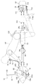
図1から図3の説明に戻ると、水密容器14には、水中スクータ10を潜行あるいは浮上させて航行深度を調整する深度調整機構18が取り付けられる。深度調整機構18は、バー100と、円筒状の左右のグリップ102L,102Rと、上面視略台形のプレートからなる左右のエレベータ104L,104Rと、グリップ102L,102Rをエレベータ104L,104Rに接続する接続部材106L,106Rとからなる。   Returning to the description of FIG. 1 to FIG. 3, the watertight container 14 is provided with a depth adjustment mechanism 18 that adjusts the navigation depth by causing the underwater scooter 10 to dive or float. The depth adjusting mechanism 18 includes a bar 100, cylindrical left and right grips 102L and 102R, left and right elevators 104L and 104R made of a substantially trapezoidal plate when viewed from above, and connections for connecting the grips 102L and 102R to the elevators 104L and 104R. It consists of members 106L and 106R.

深度調整機構18について具体的に説明すると、バー100は水密容器14に取り付けられ、その長手方向が水中スクータ10の左右方向に対して平行となるように配置される。バー100において進行方向に向かって左側の端部には、左グリップ102Lが取り付けられる。同様に、バー100において進行方向に向かって右側の端部には、右グリップ102Rが取り付けられる。尚、左右のグリップ102L,102Rは、それぞれバー100を中心として回転(具体的には自転)自在に取り付けられる。   The depth adjusting mechanism 18 will be described in detail. The bar 100 is attached to the watertight container 14 and is arranged so that its longitudinal direction is parallel to the left-right direction of the underwater scooter 10. A left grip 102L is attached to the left end of the bar 100 in the traveling direction. Similarly, a right grip 102R is attached to the right end of the bar 100 in the traveling direction. The left and right grips 102L and 102R are attached so as to be rotatable (specifically, rotate) around the bar 100, respectively.

左右のグリップ102L,102Rには、それぞれ接続部材106L,106Rを介してエレベータ104L,104Rが接続される。これにより、エレベータ104L,104Rは、水密容器14の両側に配置されると共に、水中スクータ10の左右軸回りに揺動自在とされる。即ち、グリップ102L,102Rを回転させることにより、水密容器14の両側に配置されたエレベータ104L,104Rを左右軸回りに揺動させてその傾きの大きさと方向を変更することができ、よってエレベータ104L,104Rに作用する揚力(水中スクータ10を潜行あるいは浮上させる力)を調整することができる。   Elevators 104L and 104R are connected to the left and right grips 102L and 102R via connecting members 106L and 106R, respectively. As a result, the elevators 104L and 104R are arranged on both sides of the watertight container 14 and can swing around the left and right axes of the underwater scooter 10. That is, by rotating the grips 102L and 102R, the elevators 104L and 104R arranged on both sides of the watertight container 14 can be swung around the left and right axes, and the magnitude and direction of the inclination can be changed. , 104R (the force that causes the underwater scooter 10 to submerge or float) can be adjusted.

また、バー100の適宜位置には、エマージェンシスイッチ110が設けられる。エマージェンシスイッチ110には、そのオン、オフのトリガーとなるエマージェンシコード112(図1および図3に示す)の一端が取り付けられる。エマージェンシコード112の他端は、後述する如く、操縦者の腕に取り付けられる。   Further, an emergency switch 110 is provided at an appropriate position of the bar 100. The emergency switch 110 is attached with one end of an emergency cord 112 (shown in FIG. 1 and FIG. 3) that is an on / off trigger. The other end of the emergency cord 112 is attached to the operator's arm as will be described later.

一方、メインフレーム12の後端には、操舵機構20が取り付けられる。操舵機構20は、フットスタンド114と、フットスタンド114に接続されたラダー116と、それらをメインフレーム12の後端に接続する接続部材118とからなる。   On the other hand, a steering mechanism 20 is attached to the rear end of the main frame 12. The steering mechanism 20 includes a foot stand 114, a ladder 116 connected to the foot stand 114, and a connection member 118 that connects them to the rear end of the main frame 12.

操舵機構20について具体的に説明すると、接続部材118は、メインフレーム12の直径と略同径の内径を有する円筒部118aを備える。図12に良く示すように、かかる円筒部118aにメインフレーム12の後端を挿入し、ちょうボルト120をメインフレーム12の内部に収容されたナット122に螺合させることにより、メインフレーム12に接続部材118、別言すれば、操舵機構20が取り付けられる。尚、図示は省略するが、ナット122も前述のナット62と同様に周囲を区画壁で囲われ、その回転が抑止される。   The steering mechanism 20 will be specifically described. The connection member 118 includes a cylindrical portion 118 a having an inner diameter that is substantially the same as the diameter of the main frame 12. As shown well in FIG. 12, the rear end of the main frame 12 is inserted into the cylindrical portion 118 a, and the butterfly bolt 120 is screwed into a nut 122 accommodated in the main frame 12 to be connected to the main frame 12. The member 118, in other words, the steering mechanism 20 is attached. Although illustration is omitted, the nut 122 is also surrounded by a partition wall in the same manner as the nut 62 described above, and its rotation is suppressed.

接続部材118は、前記円筒部118aに連続する上下左右の計4枚の翼部118bを備える。翼部118bは、プロペラ16との接触を上下方向あるいは左右方向に回避するように形成されると共に、それらの後端は、プロペラ16よりも後方に位置させられる。上記したフットスタンド114とそれに接続されたラダー116は、翼部118bの中、上下に配置された2枚の翼部の後端に上下軸回りに揺動自在に支持される。即ち、フットスタンド114を操作する(上下軸回りに回転させる)ことにより、ラダー116を上下軸回りに揺動させることができ、よって水中スクータ10の進行方向を調整することができる。   The connecting member 118 includes a total of four wings 118b on the top, bottom, left, and right that are continuous with the cylindrical part 118a. The wings 118b are formed so as to avoid contact with the propeller 16 in the up-down direction or the left-right direction, and their rear ends are positioned rearward of the propeller 16. The above-mentioned foot stand 114 and the ladder 116 connected thereto are supported so as to be swingable around the vertical axis at the rear ends of the two wing portions arranged vertically in the wing portion 118b. That is, by operating the foot stand 114 (rotating about the vertical axis), the ladder 116 can be swung about the vertical axis, and thus the traveling direction of the underwater scooter 10 can be adjusted.

図13は、水中スクータ10と、それに騎乗した操縦者を示す左側面図である。   FIG. 13 is a left side view showing the underwater scooter 10 and the rider riding it.

図13に示すように、操縦者OPは、第1のエアタンク22と第2のエアタンク24の上に騎乗する。具体的には、操縦者OPは、メインフレーム12を跨ぐようにして第1のエアタンク22と第2のエアタンク24に着座する。そして、前傾姿勢をとり、前方に位置する水密容器14の左右に配置されたグリップ102L,102Rを把持すると共に、後方に位置するフットスタンド114の載置部114aに足を載置する、具体的には、足の甲を係止させる。尚、載置部114aは、図1に示すように、平面視において環状を呈する。   As shown in FIG. 13, the pilot OP rides on the first air tank 22 and the second air tank 24. Specifically, the pilot OP sits on the first air tank 22 and the second air tank 24 so as to straddle the main frame 12. Then, it takes a forward leaning posture, grips the grips 102L and 102R disposed on the left and right of the watertight container 14 located in the front, and places the foot on the placement part 114a of the foot stand 114 located in the rear. Specifically, the instep is locked. In addition, the mounting part 114a exhibits a ring shape in a plan view as shown in FIG.

このとき、操縦者OPの腰部は、前記したスライダ30L,30Rに取り付けられたウェストホルダ126に支持される。また、操縦者OPの膝裏は、メインフレーム12に取り付けられたフットホルダ128に支持される。尚、フットホルダ128は、前述した接続部材60などと同様に、メインフレーム12の内部に収容されてその回転が抑止されたナット(図示せず)とちょうボルト130を螺合させることによって取り付けられる。   At this time, the waist of the pilot OP is supported by the waist holder 126 attached to the sliders 30L and 30R. Further, the back of the knee of the operator OP is supported by a foot holder 128 attached to the main frame 12. The foot holder 128 is attached by screwing a nut bolt (not shown) housed inside the main frame 12 and restrained from rotating with the wing bolt 130, like the connection member 60 described above. .

また、操縦者OPの腕には、前述したエマージェンシコード112(図13で図示省略)の他端が装着される。これにより、操縦者OPが水中スクータ10から離脱したときにエマージェンシコード112の一端がエマージェンシスイッチ110から引き抜かれ、緊急停止信号が送出されてエンジンEが停止させられる。   Further, the other end of the emergency cord 112 (not shown in FIG. 13) is attached to the arm of the operator OP. As a result, when the operator OP leaves the underwater scooter 10, one end of the emergency cord 112 is pulled out from the emergency switch 110, an emergency stop signal is sent, and the engine E is stopped.

ここで、水中スクータ10が航行すると、前述の如く、進行方向前方に向けて開口された取水口66aから水路66に水が流入する。水路66に流入した水は、そこで水密容器14内の空気と熱交換されて暖められた後、進行方向後方に向けて開口された排水口66bから水中スクータ10の後方、具体的には、操縦者OPへと排出される。即ち、流路66に流入した水は、水密容器14の内部(具体的には、そこに収容されたエンジンE)を冷却する冷却水として用いられた後、体を温めるための温水として操縦者OPに供給される。   Here, when the underwater scooter 10 navigates, as described above, water flows into the water channel 66 from the water intake 66a that opens forward in the traveling direction. The water flowing into the water channel 66 is heated and exchanged with the air in the watertight container 14, and then the rear side of the underwater scooter 10, specifically, the maneuvering from the drain port 66 b opened rearward in the traveling direction. Is discharged to the OP. That is, the water that has flowed into the flow path 66 is used as cooling water for cooling the inside of the watertight container 14 (specifically, the engine E accommodated therein), and is then used as warm water for warming the body. Supplied to OP.

次いで、操縦者OPによる水中スクータ10の操縦、具体的には、航行深度と進行方向の調整について説明する。   Next, the operation of the underwater scooter 10 by the operator OP, specifically, the adjustment of the navigation depth and the traveling direction will be described.

先ず、水中スクータ10を潜行させるときは、図14に示す如く、左右のエレベータ104L,104Rの前端を後端よりも下方に位置させるように左右のグリップ102L,102Rを回転させる。この状態で水中スクータ10を前進させることにより、左右のエレベータ104L,104Rには下向きの力が作用し、よって水中スクータ10が潜行させられる。また、このとき、操縦者OPは騎乗部たる第1および第2のエアタンク22,24を後方へとスライドさせる。即ち、第1および第2のエアタンク22,24の浮力が作用する位置を後方へと移動させる。これにより、水中スクータ10の後方の浮力が大きくなり、水中スクータ10の前方が沈み込む(後方が浮き上がる)ことから、潜行に適した(潜行し易い)姿勢となる。   First, when the underwater scooter 10 is submerged, as shown in FIG. 14, the left and right grips 102L and 102R are rotated so that the front ends of the left and right elevators 104L and 104R are positioned below the rear end. By advancing the underwater scooter 10 in this state, a downward force is applied to the left and right elevators 104L and 104R, so that the underwater scooter 10 is submerged. At this time, the pilot OP slides the first and second air tanks 22 and 24, which are riding parts, backward. That is, the position where the buoyancy of the first and second air tanks 22 and 24 acts is moved backward. As a result, the buoyancy behind the underwater scooter 10 increases, and the front of the underwater scooter 10 sinks (the rear rises), so that the posture is suitable for diving (easy to dive).

これに対し、水中スクータ10を浮上させるときは、図15に示す如く、左右のエレベータ104L,104Rの前端を後端よりも上方に位置させるように左右のグリップ102L,102Rを回転させる。この状態で水中スクータ10を前進させることにより、左右のエレベータ104L,104Rには上向きの力が作用し、よって水中スクータ10が浮上させられる。また、このとき、操縦者OPは騎乗部たる第1および第2のエアタンク22,24を前方へとスライドさせる。即ち、第1および第2のエアタンク22,24の浮力が作用する位置を前方へと移動させる。これにより、水中スクータ10の前方の浮力が大きくなり、水中スクータ10の前方が浮き上がる(後方が沈み込む)ことから、浮上に適した(浮上し易い)姿勢となる。   On the other hand, when the underwater scooter 10 is levitated, the left and right grips 102L and 102R are rotated so that the front ends of the left and right elevators 104L and 104R are positioned above the rear end, as shown in FIG. By advancing the underwater scooter 10 in this state, an upward force acts on the left and right elevators 104L, 104R, and thus the underwater scooter 10 is lifted. At this time, the pilot OP slides the first and second air tanks 22 and 24, which are riding parts, forward. That is, the position where the buoyancy of the first and second air tanks 22 and 24 acts is moved forward. As a result, the buoyancy in front of the underwater scooter 10 is increased and the front of the underwater scooter 10 is lifted (back sinks), so that the posture is suitable for floating (easy to float).

一方、水中スクータ10の進行方向を調整するときは、フットスタンド114に載置した足でフットスタンド114を左右に操作し、よってラダー116を上下軸回りに揺動させる。これにより、水中スクータ10が左右に操舵される。   On the other hand, when the traveling direction of the underwater scooter 10 is adjusted, the foot stand 114 is operated left and right with the foot placed on the foot stand 114, and thus the ladder 116 is swung around the vertical axis. Thereby, the underwater scooter 10 is steered left and right.

このように、この実施例に係る水中スクータ10にあっては、操縦者OPの前方に配置された水密容器14と、水密容器14に収容されたエンジンEと、水密容器14において前方に向けて開口された取水口66aと、水密容器14において後方に向けて開口された排水口66bと、エンジンEの近傍を通過して前記取水口66aと排水口66bを連通する水路66とを設けるようにしたので、水路66に流入した水と水密容器14内の空気との間で熱交換がなされるため、エンジンEの放熱性が向上し、よってオーバーヒートを防止することができる。また、かかる熱交換によって暖められた水(温水)が排水口66bから操縦者に向かって排出される(供給される)ため、操縦者の体を温めることができ、よって快適性を向上させることができる。   Thus, in the underwater scooter 10 according to this embodiment, the watertight container 14 disposed in front of the operator OP, the engine E accommodated in the watertight container 14, and the watertight container 14 facing forward. An open water intake 66a, a drain port 66b opened rearward in the watertight container 14, and a water channel 66 that passes through the vicinity of the engine E and communicates with the water intake 66a and the drain port 66b are provided. Therefore, heat exchange is performed between the water flowing into the water channel 66 and the air in the watertight container 14, so that the heat dissipation of the engine E is improved, and thus overheating can be prevented. Further, since water (warm water) warmed by such heat exchange is discharged (supplied) from the drain port 66b toward the operator, the body of the operator can be warmed, thereby improving comfort. Can do.

また、水路66の周囲に、水路66を流れる流体と水密容器14内の空気との間の熱交換を促進するフィン66cを設けるようにしたので、エンジンEの放熱性をより向上させることができると共に、操縦者に供給される水(温水)をより効率的に昇温させることができる。このため、簡素な構成でありながら、エンジンEのオーバーヒートを一層効果的に防止することができると共に、操縦者の保温性が向上し、快適性を一層向上させることができる。   Further, since the fin 66c that promotes heat exchange between the fluid flowing in the water channel 66 and the air in the watertight container 14 is provided around the water channel 66, the heat dissipation of the engine E can be further improved. At the same time, the temperature of the water (hot water) supplied to the operator can be raised more efficiently. Therefore, overheating of the engine E can be more effectively prevented while the structure is simple, and the heat retaining property of the operator is improved, and the comfort can be further improved.

また、メインフレーム12に騎乗部たる第1および第2のエアタンク22,24を配置し、そこに操縦者が騎乗するようにしたので、操縦者を牽引するタイプの従来例に比して操縦者の負担を軽減させることができる。   In addition, the first and second air tanks 22 and 24, which are riding parts, are arranged on the main frame 12 so that the driver rides on the first and second air tanks. Can be reduced.

また、プロペラ16が、操縦者が騎乗するメインフレーム12の後方に配置されることから、プロペラ16から噴出された水流によって操縦者の体が冷やされることもない。   In addition, since the propeller 16 is disposed behind the main frame 12 on which the pilot rides, the pilot's body is not cooled by the water flow ejected from the propeller 16.

また、第1のエアタンク22に封入された空気をエンジンEの燃焼用空気として供給すると共に、第2のエアタンク24に封入された空気を操縦者OPの呼吸用空気として供給するようにしたので、水上および水中での航行が可能になると共に、操縦者の快適性を向上させることができる。   In addition, the air sealed in the first air tank 22 is supplied as combustion air for the engine E, and the air sealed in the second air tank 24 is supplied as air for breathing of the operator OP. Navigation on the water and underwater becomes possible, and the comfort of the operator can be improved.

また、第1および第2のエアタンク22,24を水中スクータ10の進行方向にスライド自在とし、それらの浮力が作用する位置を可変としたことから、水中スクータ10を潜行または浮上に適した姿勢にすることができ、よって水中スクータ10の深度調整を容易に行うことができる。   In addition, since the first and second air tanks 22 and 24 are slidable in the traveling direction of the underwater scooter 10 and the positions where their buoyancy acts are made variable, the underwater scooter 10 has a posture suitable for diving or ascending. Therefore, the depth adjustment of the underwater scooter 10 can be easily performed.

以上の如く、この発明の第1実施例にあっては、操縦者(OP)に操縦されて水上または水中を航行する水中スクータ(10)において、前記操縦者(OP)の前方に配置された水密容器(14)と、前記水密容器(14)に収容された駆動源(エンジンE)と、前記駆動源(E)に駆動されて前記水中スクータ(10)を推進させるプロペラ(16)と、前記水密容器(14)において前方に向けて開口された取水口(66a)と、前記水密容器(14)において後方に向けて開口された排水口(66b)と、前記駆動源(E)の近傍を通過して前記取水口(66a)と前記排水口(66b)を連通する水路(66)とを備えるように構成した。   As described above, in the first embodiment of the present invention, in the underwater scooter (10) that is operated by the operator (OP) and sails on the water or underwater, it is disposed in front of the operator (OP). A watertight container (14), a drive source (engine E) housed in the watertight container (14), a propeller (16) driven by the drive source (E) to propel the underwater scooter (10), In the vicinity of the drive source (E), a water intake port (66a) opened forward in the watertight container (14), a drain port (66b) opened backward in the watertight container (14). And a water channel (66) communicating with the water intake port (66a) and the water discharge port (66b).

また、前記水路(66)が、前記水密容器(14)内の空気と前記水路(66)を流れる流体との間の熱交換を促進する受熱手段、具体的には、前記水路(66)の周囲に設けられたフィン(66c)を備えるように構成した。   The water channel (66) is a heat receiving means for promoting heat exchange between the air in the watertight container (14) and the fluid flowing through the water channel (66), specifically, the water channel (66). It comprised so that the fin (66c) provided in the circumference | surroundings might be provided.

尚、上記において、プロペラ16を駆動する駆動源としてエンジンEを例に挙げたが、運転に伴って発熱するものであれば、他の駆動源にも適用することができる。   In the above description, the engine E is taken as an example of a drive source for driving the propeller 16; however, any other drive source may be used as long as it generates heat during operation.

また、水路66の途中にウォーターポンプを設け、水路66内の水の流れを強制的に作り出すようにしても良い。さらに、エンジンEにウォータージャケット(冷却水通路)を設けると共に、前記ウォータージャケットの入口と出口を水路66に接続し、前記ウォーターポンプによって前記ウォータージャケットに流体(冷却水)を供給するようにしても良い。また、エンジンEのクランクシャフトESにファンを設け、水密容器14内の空気を循環させるようにしても良い。   In addition, a water pump may be provided in the middle of the water channel 66 to forcibly create the water flow in the water channel 66. Further, a water jacket (cooling water passage) is provided in the engine E, and an inlet and an outlet of the water jacket are connected to a water channel 66, and fluid (cooling water) is supplied to the water jacket by the water pump. good. Further, a fan may be provided on the crankshaft ES of the engine E so that the air in the watertight container 14 is circulated.

また、水中スクータ10が水上あるいは水面付近を航行するとき(即ち、航行深度が浅く、シュノーケル48の上端が水面より上方に位置するとき)は、シュノーケル48の上端からスタータグリップ92を取り外して前記切り欠き部48aに係止させる(即ち、開口部を封止しないようにする)ことで、外気をエンジンEの燃焼用空気として取り入れるようにしても良い。このとき、第1のエアタンク22に接続されたバルブ36を閉弁し、第1のエアタンク22からの空気の供給を停止することで、タンク内に封入された空気の消費量を低減することができる。   Further, when the underwater scooter 10 navigates on or near the water surface (that is, when the navigation depth is shallow and the upper end of the snorkel 48 is located above the water surface), the starter grip 92 is removed from the upper end of the snorkel 48 and the cutting is performed. You may make it take in external air as combustion air of the engine E by making it latch to the notch part 48a (that is, it does not seal an opening part). At this time, by closing the valve 36 connected to the first air tank 22 and stopping the supply of air from the first air tank 22, the consumption of air enclosed in the tank can be reduced. it can.

さらに、シュノーケル48とマウスピース76を接続し、水中スクータ10が水上を航行するときは操縦者の呼吸用空気も外部から導入するようにしても良い。このとき、第2のエアタンク24に接続されたバルブ42を閉弁し、第2のエアタンク24からの空気の供給を停止することで、同様に封入された空気の消費量を低減することができる。   Further, the snorkel 48 and the mouthpiece 76 may be connected, and when the underwater scooter 10 sails on the water, the air for the driver's breathing may be introduced from the outside. At this time, by closing the valve 42 connected to the second air tank 24 and stopping the supply of air from the second air tank 24, the consumption of the enclosed air can be reduced similarly. .

この発明の第1実施例に係る水中スクータの平面図である。It is a top view of the underwater scooter which concerns on 1st Example of this invention. 図1に示す水中スクータの左側面図である。It is a left view of the underwater scooter shown in FIG. 図1に示す水中スクータの正面図である。It is a front view of the underwater scooter shown in FIG. 図1のIV−IV線拡大断面図である。It is the IV-IV line expanded sectional view of FIG. 図1のV−V線拡大断面図である。It is the VV line expanded sectional view of FIG. 図2のVI−VI線拡大断面図である。FIG. 6 is an enlarged sectional view taken along line VI-VI in FIG. 2. 図5のVII−VII線拡大断面図である。It is the VII-VII line expanded sectional view of FIG. 図5などに示すシュノーケルの上端付近の拡大図である。FIG. 6 is an enlarged view near the upper end of the snorkel shown in FIG. 5 and the like. 図8のIX−IX線断面図である。It is the IX-IX sectional view taken on the line of FIG. 図5などに示す水路の側面図である。FIG. 6 is a side view of the water channel shown in FIG. 5 and the like. 図5などに示す水路の平面図である。It is a top view of the waterway shown in FIG. 図1のXII−XII線拡大断面図である。It is the XII-XII line expanded sectional view of FIG. 図1に示す水中スクータと、それに騎乗した操縦者を示す左側面図である。FIG. 2 is a left side view showing the underwater scooter shown in FIG. 1 and a driver riding on it. 同様に、図1に示す水中スクータと、それに騎乗した操縦者を示す左側面図である。Similarly, it is the left view which shows the underwater scooter shown in FIG. 1, and the driver who mounted on it. 同様に、図1に示す水中スクータと、それに騎乗した操縦者を示す左側面図である。Similarly, it is the left view which shows the underwater scooter shown in FIG. 1, and the driver who mounted on it.

符号の説明Explanation of symbols

10 水中スクータ
14 水密容器
16 プロペラ
66 水路
66a 取水口
66b 排水口
66c フィン(受熱手段)
E エンジン(駆動源)
DESCRIPTION OF SYMBOLS 10 Underwater scooter 14 Watertight container 16 Propeller 66 Water channel 66a Intake port 66b Drain port 66c Fin (heat receiving means)
E Engine (drive source)

Claims (3)

操縦者に操縦されて水上または水中を航行する水中スクータにおいて、前記操縦者の前方に配置された水密容器と、前記水密容器に収容された駆動源と、前記駆動源に駆動されて前記水中スクータを推進させるプロペラと、前記水密容器において前方に向けて開口された取水口と、前記水密容器において後方に向けて開口された排水口と、前記駆動源の近傍を通過して前記取水口と前記排水口を連通する水路とを備えることを特徴とする水中スクータ。   An underwater scooter that is piloted by a pilot and sails on or under water, a watertight container disposed in front of the operator, a drive source accommodated in the watertight container, and the underwater scooter driven by the drive source. A propeller that propels the watertight container, a water intake opening that opens toward the front in the watertight container, a drainage opening that opens to the rear in the watertight container, the vicinity of the drive source, and the water intake and the An underwater scooter comprising a water channel communicating with a drain outlet. 前記水路が、前記水密容器内の空気と前記水路を流れる流体との間の熱交換を促進する受熱手段を備えることを特徴とする請求項1記載の水中スクータ。   The underwater scooter according to claim 1, wherein the water channel includes heat receiving means for promoting heat exchange between air in the watertight container and a fluid flowing through the water channel. 前記受熱手段が、前記水路の周囲に設けられたフィンからなることを特徴とする請求項2記載の水中スクータ。
The underwater scooter according to claim 2, wherein the heat receiving means includes fins provided around the water channel.
JP2004116160A 2004-04-09 2004-04-09 Underwater scooter Withdrawn JP2005297746A (en)

Priority Applications (2)

Application Number Priority Date Filing Date Title
JP2004116160A JP2005297746A (en) 2004-04-09 2004-04-09 Underwater scooter
US11/102,163 US7011035B2 (en) 2004-04-09 2005-04-08 Underwater scooter

Applications Claiming Priority (1)

Application Number Priority Date Filing Date Title
JP2004116160A JP2005297746A (en) 2004-04-09 2004-04-09 Underwater scooter

Publications (1)

Publication Number Publication Date
JP2005297746A true JP2005297746A (en) 2005-10-27

Family

ID=35329819

Family Applications (1)

Application Number Title Priority Date Filing Date
JP2004116160A Withdrawn JP2005297746A (en) 2004-04-09 2004-04-09 Underwater scooter

Country Status (1)

Country Link
JP (1) JP2005297746A (en)

Cited By (1)

* Cited by examiner, † Cited by third party
Publication number Priority date Publication date Assignee Title
JP2007168534A (en) * 2005-12-20 2007-07-05 Honda Motor Co Ltd Underwater scooter

Cited By (1)

* Cited by examiner, † Cited by third party
Publication number Priority date Publication date Assignee Title
JP2007168534A (en) * 2005-12-20 2007-07-05 Honda Motor Co Ltd Underwater scooter

Similar Documents

Publication Publication Date Title
US5449305A (en) Watercraft
US20050223961A1 (en) Hybrid-powered underwater scooter
FR2617793A1 (en) Motor board
US10494074B1 (en) Intercooler for a watercraft
JP2005297746A (en) Underwater scooter
JP2005001518A (en) Small vessel
JP4219847B2 (en) Underwater scooter
JP4219845B2 (en) Underwater scooter
US7011035B2 (en) Underwater scooter
JP4219849B2 (en) Underwater scooter
JP2005297738A (en) Underwater scooter
US7992510B2 (en) Personal watercraft
JP4219846B2 (en) Underwater scooter
JP2005297745A (en) Underwater scooter
JPH0657555B2 (en) Small water vehicle
JP2005297739A (en) Underwater scooter
JP2005297744A (en) Underwater scooter
JP2005297740A (en) Underwater scooter
JPH1179093A (en) Hydroplane
JP4282433B2 (en) Small jet propulsion boat
US20050252437A1 (en) Underwater scooter
US7458869B2 (en) Personal watercraft
US3908578A (en) Exhaust systems for aquatic craft
JP4046182B2 (en) Small planing boat
JP3904660B2 (en) Saddle-type small vessel

Legal Events

Date Code Title Description
A300 Application deemed to be withdrawn because no request for examination was validly filed

Free format text: JAPANESE INTERMEDIATE CODE: A300

Effective date: 20070703