JP2005297745A - Underwater scooter - Google Patents
Underwater scooter Download PDFInfo
- Publication number
- JP2005297745A JP2005297745A JP2004116159A JP2004116159A JP2005297745A JP 2005297745 A JP2005297745 A JP 2005297745A JP 2004116159 A JP2004116159 A JP 2004116159A JP 2004116159 A JP2004116159 A JP 2004116159A JP 2005297745 A JP2005297745 A JP 2005297745A
- Authority
- JP
- Japan
- Prior art keywords
- propeller
- main frame
- underwater scooter
- vertical axis
- propeller shaft
- Prior art date
- Legal status (The legal status is an assumption and is not a legal conclusion. Google has not performed a legal analysis and makes no representation as to the accuracy of the status listed.)
- Withdrawn
Links
Images


Landscapes
- Automatic Cycles, And Cycles In General (AREA)
Abstract
【課題】操縦者の負担、特に、旋回時の負担を軽減すると共に、高い旋回性能を得るようにした水中スクータを提供する。
【解決手段】操縦者(OP)の騎乗部たる第1のエアタンク(22)と第2のエアタンク(24)が配置されたメインフレーム(12)と、メインフレームの前方に配置された水密容器(14)に収容されたエンジンと、メインフレームの後方に配置されたプロペラ(16)と、エンジンの出力によって回転させられるドライブシャフトと、ドライブシャフトの回転をプロペラに接続されたプロペラシャフトに伝達するユニバーサルジョイント(20)とを備えると共に、プロペラ揺動機構(130)を操作することによってユニバーサルジョイントを支点としてプロペラシャフトとそれに接続されたプロペラを上下軸回りに揺動させ、よって水中スクータ(10)を旋回させる。
【選択図】図1An underwater scooter is provided that reduces the burden on a driver, in particular, the burden at the time of turning, and obtains high turning performance.
A main frame (12) in which a first air tank (22) and a second air tank (24) as a riding section of an operator (OP) are arranged, and a watertight container (in front of the main frame) ( 14), the propeller (16) disposed behind the main frame, the drive shaft that is rotated by the output of the engine, and the universal that transmits the rotation of the drive shaft to the propeller shaft connected to the propeller A joint (20), and by operating the propeller swing mechanism (130), the propeller shaft and the propeller connected thereto are swung around the vertical axis with the universal joint as a fulcrum, and thus the underwater scooter (10) is Turn.
[Selection] Figure 1
Description
この発明は、水上または水中を航行する水中スクータに関する。 The present invention relates to an underwater scooter that sails on water or underwater.
従来、操縦者(ダイバー)に操縦されて水上または水中を航行する水中スクータが提案されている。この種の水中スクータにあっては、一般に、内燃機関あるいは電動モータを駆動源としてプロペラを駆動することによって推進力を得る。そして、操縦者が把持すべきグリップを備え、かかるグリップを把持した操縦者を牽引することにより、その進行を補助するように構成している(例えば特許文献1参照)。
特許文献1に記載されるような牽引型の水中スクータにあっては、プロペラの向きを水中スクータごと調整することによって旋回が行われるため、旋回性能に優れる(小回りが利く)という利点がある。しかしながら、この種の水中スクータにあっては、牽引されている間、操縦者はグリップを把持し続けなければならないため、腕が疲労し易く、負担が大きいという不具合があった。特に、旋回時は、上記の如くプロペラの向きを水中スクータごと調整しなければならないため、旋回性能に優れるという利点がある一方で、操縦者の負担も大きかった。 The towing-type underwater scooter described in Patent Document 1 has an advantage that the turning performance is excellent (small turning is effective) because the turning is performed by adjusting the direction of the propeller together with the underwater scooter. However, in this type of underwater scooter, the operator has to keep gripping the grip while being pulled, so that there is a problem that the arm is easily fatigued and the load is large. In particular, during turning, the propeller direction must be adjusted with the underwater scooter as described above. This has the advantage of excellent turning performance, but also places a heavy burden on the operator.
従って、この発明の目的は上記した課題を解決することにあり、操縦者の負担、特に、旋回時の負担を軽減すると共に、高い旋回性能を得るようにした水中スクータを提供することにある。 Accordingly, an object of the present invention is to solve the above-described problems, and to provide an underwater scooter that can reduce the burden on the operator, in particular, the burden during turning, and obtain high turning performance.
上記した課題を解決するために、請求項1にあっては、操縦者に操縦されて水上または水中を航行する水中スクータにおいて、前記操縦者が騎乗すべき騎乗部が配置されたメインフレームと、前記メインフレームの前記水中スクータの進行方向において前方に配置された水密容器と、前記水密容器に収容された駆動源と、前記メインフレームの内部に挿通されて前記駆動源の出力によって回転させられるドライブシャフトと、前記メインフレームの前記進行方向において後方に配置されたプロペラと、前記プロペラに接続されたプロペラシャフトと、前記ドライブシャフトの回転を前記プロペラシャフトに伝達するユニバーサルジョイントと、および前記ユニバーサルジョイントを支点として前記プロペラシャフトを上下軸回りに揺動させ、よって前記プロペラを上下軸回りに揺動させるプロペラ揺動機構とを備えるように構成した。 In order to solve the above-mentioned problem, in claim 1, in a submersible scooter that is piloted by a pilot and sails on or under water, a main frame on which a riding section on which the pilot should ride is disposed; A watertight container disposed forward of the underwater scooter in the main frame, a drive source housed in the watertight container, and a drive inserted into the main frame and rotated by the output of the drive source A shaft, a propeller disposed rearward in the traveling direction of the main frame, a propeller shaft connected to the propeller, a universal joint that transmits rotation of the drive shaft to the propeller shaft, and the universal joint The propeller shaft is swung around the vertical axis as a fulcrum, Was configured with a propeller swinging mechanism for swinging the propeller up and down axis I.
また、請求項2にあっては、前記騎乗部よりも前記進行方向において前方に配置された前記水中スクータの航行深度を調整する深度調整機構を備えると共に、前記プロペラ揺動機構が、前記深度調整機構を上下軸回りに揺動自在とする深度調整機構揺動機構と、前記深度調整機構の上下軸回りの揺動角変位を前記プロペラシャフトが挿通されるプロペラシャフトケースに伝達して前記プロペラシャフトを上下軸回りに揺動させる揺動角変位伝達機構とからなるように構成した。 Further, according to claim 2, a depth adjustment mechanism that adjusts a navigation depth of the underwater scooter disposed in front of the riding section in the traveling direction is provided, and the propeller swinging mechanism includes the depth adjustment A depth adjusting mechanism swinging mechanism that allows the mechanism to swing about a vertical axis, and a swing angular displacement of the depth adjusting mechanism about the vertical axis is transmitted to a propeller shaft case through which the propeller shaft is inserted to transmit the propeller shaft Is configured to include a rocking angular displacement transmission mechanism that rocks around the vertical axis.
また、請求項3にあっては、前記プロペラ揺動機構が、前記プロペラシャフトが挿通されるプロペラシャフトケースに取り付けられた前記操縦者の足で操作されるべきフットスタンドからなるように構成した。 According to a third aspect of the present invention, the propeller swinging mechanism includes a foot stand to be operated by the operator's foot attached to a propeller shaft case through which the propeller shaft is inserted.
請求項1に係る水中スクータにあっては、操縦者が騎乗すべき騎乗部が配置されたメインフレームと、メインフレームの前方に配置された水密容器と、水密容器に収容された駆動源と、メインフレームの内部に挿通されて駆動源の出力によって回転させられるドライブシャフトと、メインフレームの後方に配置されたプロペラと、プロペラに接続されたプロペラシャフトと、ドライブシャフトの回転をプロペラシャフトに伝達するユニバーサルジョイントと、ユニバーサルジョイントを支点としてプロペラシャフトを上下軸回りに揺動させ、よってプロペラを上下軸回りに揺動させるプロペラ揺動機構とを備えるように構成したので、水中スクータの航行中、操縦者はメインフレームに騎乗することができると共に、プロペラ揺動機構を操作することによってプロペラを上下軸回りに揺動させて(プロペラの向きを調整して)水中スクータを旋回させることができる。このため、牽引型の従来例に比して操縦者の負担、特に、旋回時の負担を軽減することができると共に、高い旋回性能を得ることができる。 In the underwater scooter according to claim 1, a main frame on which a rider to ride a pilot is disposed, a watertight container disposed in front of the main frame, a drive source accommodated in the watertight container, A drive shaft that is inserted into the main frame and rotated by the output of the drive source, a propeller disposed behind the main frame, a propeller shaft connected to the propeller, and the rotation of the drive shaft are transmitted to the propeller shaft. Since it is configured to include a universal joint and a propeller swing mechanism that swings the propeller shaft about the vertical axis with the universal joint as a fulcrum, and thus swings the propeller about the vertical axis, Can ride on the main frame and operate the propeller swing mechanism Rukoto by by swinging the propeller up and down axis (to adjust the orientation of the propeller) can be pivoted in water scooter. For this reason, it is possible to reduce the burden on the operator, in particular, the burden at the time of turning, as compared with the conventional example of the towing type, and it is possible to obtain high turning performance.
また、請求項2に係る水中スクータにあっては、騎乗部よりも前方に配置された深度調整機構を備えると共に、プロペラ揺動機構が、深度調整機構を上下軸回りに揺動自在とする深度調整機構揺動機構と、その上下軸回りの揺動角変位をプロペラシャフトケースに伝達してプロペラシャフト(およびそれに接続されたプロペラ)を上下軸回りに揺動させる揺動角変位伝達機構とからなるように構成した、換言すれば、水中スクータの航行深度と進行方向を調整するための操作系を操縦者の騎乗位置よりも前方(即ち、操作性に優れる位置)に集中して配置するように構成したので、上記した効果に加え、操作性が向上し、よって操縦者の負担を効果的に軽減することができる。 The underwater scooter according to claim 2 further includes a depth adjusting mechanism disposed in front of the riding section, and the propeller swinging mechanism allows the depth adjusting mechanism to swing about the vertical axis. The adjustment mechanism swing mechanism and the swing angle displacement transmission mechanism that transmits the swing angular displacement about the vertical axis to the propeller shaft case to swing the propeller shaft (and the propeller connected thereto) about the vertical axis. In other words, the operation system for adjusting the navigation depth and the traveling direction of the underwater scooter is concentratedly arranged in front of the rider's riding position (that is, a position with excellent operability). Thus, in addition to the above-described effects, the operability is improved, so that the burden on the driver can be effectively reduced.
また、請求項3に係る水中スクータにあっては、プロペラ揺動機構が、プロペラシャフトケースに取り付けられたフットスタンドからなるように構成したので、請求項1で述べた効果を簡素な構成で達成することができる。 In the underwater scooter according to claim 3, since the propeller swinging mechanism is constituted by a foot stand attached to the propeller shaft case, the effect described in claim 1 is achieved with a simple configuration. can do.
以下、添付図面に即してこの発明に係る水中スクータを実施するための最良の形態について説明する。 The best mode for carrying out the underwater scooter according to the present invention will be described below with reference to the accompanying drawings.
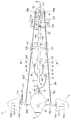
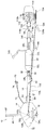
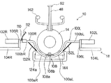
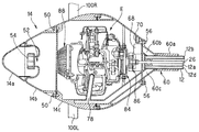
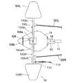
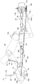
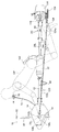
図1は、この実施例に係る水中スクータの平面図である。また、図2は、図1に示す水中スクータの左側面図であり、図3は、図1に示す水中スクータの正面図である。 FIG. 1 is a plan view of an underwater scooter according to this embodiment. 2 is a left side view of the underwater scooter shown in FIG. 1, and FIG. 3 is a front view of the underwater scooter shown in FIG.
図1から図3において、符号10は水中スクータを示す。先ず、水中スクータ10の構成について概説すると、水中スクータ10は、円筒状に形成されてその長手方向が水中スクータ10の進行方向に対して平行となるように配置されたメインフレーム12と、メインフレーム12において進行方向前方に配置された卵型の水密(気密)容器14と、水密容器14の内部に収容されたエンジン(駆動源。図1から図3で図示せず)と、メインフレーム12において進行方向後方に配置されたプロペラ16と、水中スクータ10の航行深度の調整を行う深度調整機構18と、メインフレーム12の内部に挿通されてエンジンの出力によって回転させられるドライブシャフト(図1から図3で図示せず)と、ドライブシャフトの回転をプロペラ16に接続されたプロペラシャフト(図1から図3で図示せず)に伝達するユニバーサルジョイント20と、メインフレーム12において水密容器14とプロペラ16の間に配置された第1のエアタンク22と第2のエアタンク24を備える。
1 to 3,
次いで、上記した各構成について詳説する。 Next, each of the above-described configurations will be described in detail.
図4は、図1のIV−IV線拡大断面図である。図示の如く、メインフレーム12の内部は区画壁によって分割され、5つの通路が形成される。各通路は、メインフレーム12の先端から後端まで連続する1つの空間として形成される。5つの通路のうち、中心に位置する円筒状の第1の通路12aには、前記したドライブシャフト(符号26で示す)が挿通される。これに対し、第1の通路12aの外周を分割して形成された第2から第5の通路12b,12c,12d,12eは、後述の如く、空気や排出ガスの流路となる。
4 is an enlarged sectional view taken along line IV-IV in FIG. As illustrated, the interior of the
メインフレーム12の両側面には、断面視において略Cの字状(あるいはその左右対称の断面形状)を呈する溝部28L,28Rが形成される。図2に示すように、溝部28L(およびその裏面に位置する溝部28R)は、メインフレーム12の長手方向(進行方向)に所定の長さを有するように形成される。
On both side surfaces of the
図4の説明を続けると、左右の溝部28L,28Rには、それぞれ断面視において略Hの字状を呈するスライダ30L,30Rがスライド自在に嵌められる。即ち、スライダ30L,30Rは、溝部28L,28Rの上端と下端に形成された突起をレールとして、スライド自在に構成される。
If the explanation of FIG. 4 is continued,
スライダ30L,30Rには、それぞれベルト32L,32Rが設けられる。前記した第1のエアタンク22と第2のエアタンク24は、ベルト32L,32Rを介してそれぞれスライダ30L,30Rに装着される。これにより、第1のエアタンク22と第2のエアタンク24は、メインフレーム12の長手方向(即ち、水中スクータ10の進行方向)にスライド自在に装着される。
図1から図3の説明に戻ると、第1のエアタンク22は、バルブ36を介してレギュレータ38に接続される。レギュレータ38は、ホース40を介してメインフレーム12の内部(具体的には第2の通路12b)に接続される。一方、第2のエアタンク24は、バルブ42を介してレギュレータ44に接続される。レギュレータ44は、ホース46を介してメインフレーム12の内部(具体的には、第3の通路12c)に接続される。尚、第1および第2のエアタンク22,24の容積は、例えば12リットル程度であり、その内部には空気が高圧(例えば200気圧程度)に圧縮されて封入される。
Returning to the description of FIG. 1 to FIG. 3, the
第1のエアタンク22に封入された空気は、レギュレータ38で所定の圧力(例えば10気圧程度)まで減圧された後、ホース40を介してメインフレーム12の第2の通路12bに供給される。一方、第2のエアタンク24に封入された空気は、レギュレータ44で前記した所定の圧力(10気圧程度)まで減圧された後、ホース46を介してメインフレーム12の第3の通路12cに供給される。
The air sealed in the
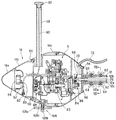
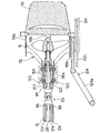
図5は、図1のV−V線拡大断面図である。また、図6は、図2のVI−VI線拡大断面図である。 FIG. 5 is an enlarged sectional view taken along line VV in FIG. 6 is an enlarged sectional view taken along line VI-VI in FIG.
図5および図6に示すように、水密容器14は、進行方向前方からバンパー14a、燃料タンク14bおよびエンジン収容部14cの3つの部材から構成される。
As shown in FIGS. 5 and 6, the
エンジン収容部14cには、エンジンEが収容される。エンジンEは、例えば排気量30cc程度の単気筒火花点火式ガソリンエンジンである。また、エンジン収容部14cの上部には、上方へと突出するシュノーケル48が設けられ、かかるシュノーケル48を介してエンジン収容部14cの内部と外部(大気)とが連通される。
The engine E is accommodated in the
エンジン収容部14cの前方には、ボルト50によって燃料タンク14bが取り付けられ、燃料タンク14bには、エンジンEに供給されるべきガソリン燃料が貯留される。また、燃料タンク14bの前面には給油口52が穿設され、給油口52は、キャップ54によって封止される。
A
燃料タンク14bの前方には、前記キャップ54を被覆するようにバンパー14aが取り付けられる。バンパー14aは、水中スクータ10が外部と衝突したときに変形して衝撃を緩和できるように、他の部材よりも硬度の小さい材料で形成される。また、バンパー14aは、燃料タンク14bへのガソリン燃料の供給を容易に行うことができるように、工具を使用することなく着脱自在とされる。
A
また、エンジン収容部14cの後方には、ボルト56によって接続部材60が取り付けられる。接続部材60は、メインフレーム12の直径と略同径の内径を有する円筒部60aを備える。
A
図7は、図5のVII−VII線拡大断面図である。図7に示すように、メインフレーム12の先端付近には、ナット62が収容される。図5から図7に示すように、接続部材60の円筒部60aにメインフレーム12の先端を挿入し、ちょうボルト64をナット62に螺合させることにより、メインフレーム12の前方に接続部材60を介して水密容器14が取り付けられる。尚、ナット62は、図7に示す如く周囲を区画壁で囲われ、その回転が抑止される。
7 is an enlarged sectional view taken along line VII-VII in FIG. As shown in FIG. 7, a
図5および図6の説明に戻ると、メインフレーム12の第2の通路12bは、接続部材60に形成された連通路60b(図6に示す)を介し、水密容器14内に配置されたレギュレータ68に接続される。また、第3の通路12cは、接続部材60の内部に形成された連通路(図示せず)と水密容器14内に設けられた流路70を介し、水密容器14の外部へと連続するホース72に接続される。ホース72の先端には、レギュレータ74が接続され、レギュレータ74には、さらにマウスピース76(いずれも図1および図2に示す)が接続される。
Returning to the description of FIGS. 5 and 6, the
また、メインフレーム12の第4の通路12dは、接続部材60に形成された連通路60cを介してエンジンEの排気管78に接続される。尚、図示は省略するが、第5の通路12eは、接続部材60に形成された連通路を介して水密容器14の内部と連通される。
Further, the
エンジンEは、図示しない吸気管を備える。吸気管の入口付近にはエアフィルタが設けられると共に、その下流にはスロットルボディ(いずれも図示せず)が配置される。スロットルボディにはスロットルバルブが収容されると共に、その上流側にはキャブレタ・アシー(いずれも図示せず)が設けられる。キャブレタ・アシーには燃料管80(図5に示す)が接続される。燃料管80は燃料タンク14bの内部に連通されると共に、その先端には燃料ポンプ82が接続される。
The engine E includes an intake pipe (not shown). An air filter is provided in the vicinity of the inlet of the intake pipe, and a throttle body (both not shown) is disposed downstream thereof. A throttle valve is accommodated in the throttle body, and a carburetor assembly (both not shown) is provided upstream of the throttle valve. A fuel pipe 80 (shown in FIG. 5) is connected to the carburetor assembly. The
また、エンジンEのクランクシャフトES(図5に示す)の一端には、遠心クラッチ84が接続される。遠心クラッチ84の出力側は減速機構86に接続され、減速機構86の出力側はドライブシャフト26の前端に接続される。尚、水中スクータ10にはエンジンEの回転数を調節する図示しないスロットル装置が設けられ、遠心クラッチ84は、エンジンEの回転数が上昇させられたときにその動力を伝達する。
A
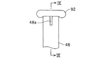
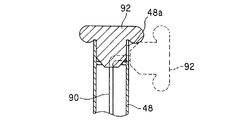
一方、クランクシャフトESの他端には、リコイルスタータ88が取り付けられる。リコイルスタータ88のスタータロープ90は、シュノーケル48の内部に挿通されると共に、その先端にはスタータグリップ92が設けられる。スタータグリップ92は、シュノーケル48の上端に着脱自在に構成される。具体的には、スタータグリップ92は、シュノーケル48の上端にその開口部を水密に封止するように装着されると共に、前記上端から取り外し自在に構成される。即ち、エンジンEを始動させる際はシュノーケル48の上端からスタータグリップ92を取り外し、スタータロープ90を引き出す。エンジンEを始動した後は、シュノーケル48から水が浸入するのを防止すべく、シュノーケル48の上端にスタータグリップ92を取り付けてその開口部を封止する。
On the other hand, a
図8は、シュノーケル48の上端付近の拡大図であり、図9は図8のIX−IX線断面図である。図8および図9に示す如く、シュノーケル48の上端には、取り外したスタータグリップ92(図9に破線で示す)を係止すべき切り欠き部48aが設けられる。
8 is an enlarged view near the upper end of the
ここで、第1のエアタンク22から所定の圧力に減圧されてメインフレーム12の第2の通路12bに供給された空気は、連通路60bを介してレギュレータ68に供給されると共に、レギュレータ68で水密容器14の内圧まで減圧された後、水密容器14の内部(具体的にはエンジン収容部14c)に供給される。
Here, the air that has been decompressed to a predetermined pressure from the
水密容器14に供給された空気は、エアフィルタを介して吸気管に吸入される。キャブレタ・アシーは、吸入された空気にガソリン燃料を噴射して混合気を生成する。生成された混合気は、エンジンEの燃焼室(図示せず)に吸入されて燃焼させられる。混合気の燃焼によって生じた排出ガスは、排気管78および連通路60cを介してメインフレーム12の第4の通路12dに流入する。
The air supplied to the
一方、第2のエアタンク24から所定の圧力に減圧されてメインフレーム12の第3の通路12cに供給された空気は、前記した連通路と流路70、さらにはホース72を介してレギュレータ74に供給される。レギュレータ74は、図示しないダイヤフラムなどを備え、マウスピース76を咥えた操縦者(ダイバー)によって吸気動作が行われたとき、周囲の水圧まで減圧した空気を操縦者に供給する。
On the other hand, the air that has been depressurized from the
このように、水中スクータ10にあっては、メインフレーム12に第1のエアタンク22を取り付け、第1のエアタンク22に封入された空気をエンジンEの燃焼用の空気として供給するようにした。また、メインフレーム12に第2のエアタンク24を取り付け、第2のエアタンク24に封入された空気を操縦者の呼吸用の空気として供給するようにした。
As described above, in the
図10は、図1のX−X線拡大断面図である。 10 is an enlarged sectional view taken along line XX in FIG.
図10に示す如く、プロペラ16には、前記したプロペラシャフト(符号16Sで示す)が接続される。プロペラシャフト16Sは、プロペラシャフトケース94に挿通されると共に、前記したユニバーサルジョイント20を介してドライブシャフト26の後端に接続される。即ち、水中スクータ10は、メインフレーム12の前方に配置されたエンジンEの出力を遠心クラッチ84、減速機構86、ドライブシャフト26、ユニバーサルジョイント20およびプロペラシャフト16Sを介してメインフレーム12の後方に配置されたプロペラ16に伝達し、よってプロペラ16を駆動して水上または水中を航行する。
As shown in FIG. 10, the propeller shaft (indicated by
また、メインフレーム12の第4の通路12dの後端には、第1のワンウェイチェックバルブ96が配置される。第1のワンウェイチェックバルブ96は、排出ガスが第4の通路12dに流入してその内圧が所定の圧力を上回ったときに開弁し、第4の通路12dを外部(水中)に連通させる。即ち、エンジンEから排出された排出ガスは、排気管78、連通路60c、メインフレーム12の第4の通路12dおよび第1のワンウェイチェックバルブ96を介して水中スクータ10の後方(外部)へと排出される。
A first one-
さらに、メインフレーム12の第5の通路12eの後端には、第2のワンウェイチェックバルブ98が配置される。第2のワンウェイチェックバルブ98は、第5の通路12eの内圧(別言すれば、第5の通路12eに連通された水密容器14の内圧)が所定の圧力を上回ったときに開弁し、第5の通路12eを外部(水中)に連通させる。即ち、エンジンEの発熱などによって水密容器14の内圧が上昇すると、水密容器14内の空気が、接続部材60に形成された連通路、メインフレーム12の第5の通路12eおよび第2のワンウェイチェックバルブ98を介して水中スクータ10の後方(外部)へと排出され、よって水密容器14の内圧が調整(減圧)される。
Further, a second one-
上記の如く、メインフレーム12に形成された第1の通路12aは、ドライブシャフト26の挿通路となる。また、第2の通路12bは、エンジンEに供給されるべき燃焼用空気の流路となり、第3の通路12cは、操縦者に供給されるべき呼吸用空気の流路となる。さらに、第4の通路12dは、エンジンEから排出された排出ガスの流路となり、第5の通路12eは、水密容器14内の空気を外部に排出してその内圧を調整するための連通路となる。
As described above, the
尚、図示は省略するが、第2の通路12bと第3の通路12cは、メインフレーム12の後端において封止される。第2の通路12bと第3の通路12cをメインフレーム12の後端で封止するのは、メインフレーム12の前端から後端に空気を充満させ、メインフレーム12全体に均等な浮力を与えるためである。第4の通路12dと第5の通路12eにおいて各ワンウェイチェックバルブをそれらの後端に配置したのも、同様な理由からである。
Although not shown, the
図1から図3の説明に戻ると、メインフレーム12の前方(上記した第1および第2のエアタンク22,24よりも前方)には、深度調整機構18が配置される。
Returning to the description of FIG. 1 to FIG. 3, the
深度調整機構18は、左右のバー100L,100Rと、円筒状の左右のグリップ102L,102Rと、上面視略台形のプレートからなる左右のエレベータ104L,104Rと、グリップ102L,102Rをエレベータ104L,104Rに接続する接続部材106L,106Rなどからなる。
The
深度調整機構18について具体的に説明すると、左右のバー100L,100Rは、図3に示す如く、水密容器14の下部から側方にかけてその外形に沿うように湾曲させられた湾曲部100aL,100aRと、湾曲部100aL,100aRに連続すると共に、水密容器14の側方(水中スクータ10の左右方向)へと水平に突出させられた直線部100bL,100bRとからなる。
The
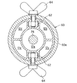
図11は、水密容器14の底面図である。
FIG. 11 is a bottom view of the
左右のバー100L,100Rの一端(湾曲部100aL,100aR側の端部)は、図3および図11に示すように、深度調整機構揺動機構108を介して水密容器14に取り付けられる。深度調整機構揺動機構108は、左右のバー100L,100Rの一端が取り付けられるプレート108aと、上下軸回りに回転自在な回転軸(後述)と、プレート108aを前記回転軸に固定するボルト108bとからなる。
As shown in FIGS. 3 and 11, one end of the left and
図5に示すように、水密容器14の下部には上記した回転軸(符号108cで示す)が設けられ、その下端にはボルト108bによってプレート108aが取り付けられる。これにより、左右のバー100L,100Rは、それらの一端を中心として上下軸回りに揺動自在とされる。
As shown in FIG. 5, the rotating shaft (indicated by
また、左右のバー100L,100Rの他端(直線部100bL,100bR側の端部)には、図1から図3に示す如く、左右のグリップ102L,102Rが取り付けられる。尚、左右のグリップ102L,102Rは、それぞれバー100L,100Rを中心として回転(具体的には自転)自在に取り付けられる。
Also, left and
左右のグリップ102L,102Rには、それぞれ接続部材106L,106Rを介してエレベータ104L,104Rが接続される。これにより、エレベータ104L,104Rは、水密容器14の両側に配置されると共に、水中スクータ10の左右軸回りに揺動自在とされる。即ち、グリップ102L,102Rを回転させることにより、水密容器14の両側に配置されたエレベータ104L,104Rを左右軸回りに揺動させてその傾きの大きさと方向を変更することができ、よってエレベータ104L,104Rに作用する揚力(水中スクータ10を潜行あるいは浮上させる力)を調整することができる。
また、右側のバー100Rの適宜位置には、エマージェンシスイッチ110が設けられる。エマージェンシスイッチ110には、そのオン、オフのトリガーとなるエマージェンシコード112(図1および図3に示す)の一端が取り付けられる。エマージェンシコード112の他端は、後述する如く、操縦者の腕に取り付けられる。
Further, an
図1から図3の説明を続けると、プロペラシャフトケース94には、尾翼116が接続部材118を介して取り付けられる。
Continuing the description of FIGS. 1 to 3, the
接続部材118は、プロペラシャフトケース94の直径と略同径の内径を有する円筒部118aを備える。図10に良く示すように、かかる円筒部118aにプロペラシャフトケース94の後端を挿入し、ちょうボルト120をプロペラシャフトケース94の内部に収容されたナット122に螺合させることにより、プロペラシャフトケース94に接続部材118が取り付けられる。尚、図示は省略するが、ナット122も前述のナット62と同様に周囲を区画壁で囲われ、その回転が抑止される。
The connecting
接続部材118は、前記円筒部118aに連続する上下左右の計4枚の翼部118bを備える。翼部118bは、プロペラ16との接触を上下方向あるいは左右方向に回避するように形成されると共に、それらの後端は、プロペラ16よりも後方に位置させられる。上記した尾翼116は、翼部118bの中、上下に配置された2枚の翼部の後端に支持される。尚、図で符号124は、操縦者の足が載置されるべきフットスタンドを示す。
The connecting
図1から図3の説明を続けると、水中スクータ10は、ユニバーサルジョイント20を支点としてプロペラシャフト16Sを上下軸回りに揺動させ、よってプロペラ16を上下軸回りに揺動させるプロペラ揺動機構130を備える。プロペラ揺動機構130は、前記した深度調整機構揺動機構108と、2本のワイヤ132L,132R(揺動角変位伝達機構)と、前記したフットスタンド124から構成される。
1 to 3, the
以下、プロペラ揺動機構130について具体的に説明すると、進行方向に向かって左側に配置されるワイヤ132Lは、その一端が深度調整機構18において左側のバー100Lに接続されると共に、他端が尾翼116の下端に取り付けられた転舵輪134に接続される。同様に、進行方向に向かって右側に配置されるワイヤ132Rは、その一端が深度調整機構18において右側のバー100Rに接続されると共に、他端が前記転舵輪134に接続される。
Hereinafter, the
これにより、深度調整機構揺動機構108によって生じた深度調整機構18の上下軸回りの変位が、ユニバーサルジョイント20よりも後方の部材に伝達される。具体的には、図12と図13に示すように、左右のバー100L,100Rを上下軸回りに揺動させることにより、その変位がワイヤ132L,132Rや転舵輪134などを介してプロペラシャフトケース94に伝達され、よってそこに挿通されたプロペラシャフト16Sと、プロペラシャフト16Sに接続されたプロペラ16とが上下軸回りに揺動される。即ち、バー100L,100Rを上下軸回りに揺動させることにより、プロペラ16を上下軸回りに揺動させてその向きを調整し(推力の発生する方向を調整し)、よって水中スクータ10を旋回させることができる。
Thereby, the displacement around the vertical axis of the
尚、各ワイヤ132L,132Rは、深度調整機構18側においてそれぞれバー100L,100R、即ち、左右軸回りの揺動を生じない部位(上下軸回りの揺動のみ行われる部位)に接続されることから、エレベータ104L,104Rを左右軸回りに揺動させても、その揺動角変位がユニバーサルジョイント20よりも後方の部材に伝達されることはない。
The
次いでフットスタンド124について説明すると、フットスタンド124は、前記したように尾翼116の下端、即ち、ユニバーサルジョイント20よりも後方側に取り付けられる。従って、フットスタンド124を操作する(上下軸回りに揺動させる)ことによっても、ユニバーサルジョイント20を支点としてプロペラシャフト16Sおよびそれに接続されたプロペラ16を上下軸回りに揺動させ、よって水中スクータ10を旋回させることができる。
Next, the
このように、プロペラ揺動機構130は、深度調整機構揺動機構108とワイヤ132L,132Rとフットスタンド124とから構成されると共に、その中の深度調整機構揺動機構108とワイヤ132L,132Rにより、プロペラ16の向きを腕によって調整することができる。また、フットスタンド114により、プロペラ16の向きを足によって調整することができる。
Thus, the
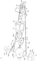
図14は、水中スクータ10と、それに騎乗した操縦者を示す左側面図である。
FIG. 14 is a left side view showing the
図14に示すように、操縦者OPは、第1のエアタンク22と第2のエアタンク24の上に騎乗する。具体的には、操縦者OPは、メインフレーム12を跨ぐようにして第1のエアタンク22と第2のエアタンク24に着座する。そして、前傾姿勢をとって前方に位置する左右のグリップ102L,102Rを把持すると共に、後方に位置するフットスタンド124の載置部124aに足を載置する、具体的には、足の甲を係止させる。尚、載置部124aは、図1に示すように、平面視において環状を呈する。
As shown in FIG. 14, the pilot OP rides on the
このとき、操縦者OPの腰部は、前記したスライダ30L,30Rに取り付けられたウェストホルダ142に支持される。また、操縦者OPの膝裏は、メインフレーム12に取り付けられたフットホルダ144に支持される。尚、フットホルダ144は、前述した接続部材60などと同様に、メインフレーム12の内部に収容されてその回転が抑止されたナット(図示せず)とちょうボルト146を螺合させることによって取り付けられる。
At this time, the waist of the pilot OP is supported by the
また、操縦者OPの腕には、前述したエマージェンシコード112(図14で図示省略)の他端が装着される。これにより、操縦者OPが水中スクータ10から離脱したときにエマージェンシコード112の一端がエマージェンシスイッチ110から引き抜かれ、緊急停止信号が送出されてエンジンEが停止させられる。
Further, the other end of the emergency cord 112 (not shown in FIG. 14) is attached to the arm of the operator OP. As a result, when the operator OP leaves the
次いで、操縦者OPによる水中スクータ10の操縦、具体的には、航行深度と進行方向の調整について説明する。
Next, the operation of the
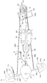
先ず、水中スクータ10を潜行させるときは、図15に示す如く、左右のエレベータ104L,104Rの前端を後端よりも下方に位置させるように左右のグリップ102L,102Rを回転させる。この状態で水中スクータ10を前進させることにより、左右のエレベータ104L,104Rには下向きの力が作用し、よって水中スクータ10が潜行させられる。また、このとき、操縦者OPは騎乗部たる第1および第2のエアタンク22,24を後方へとスライドさせる。即ち、第1および第2のエアタンク22,24の浮力が作用する位置を後方へと移動させる。これにより、水中スクータ10の後方の浮力が大きくなり、水中スクータ10の前方が沈み込む(後方が浮き上がる)ことから、潜行に適した(潜行し易い)姿勢となる。
First, when the
これに対し、水中スクータ10を浮上させるときは、図16に示す如く、左右のエレベータ104L,104Rの前端を後端よりも上方に位置させるように左右のグリップ102L,102Rを回転させる。この状態で水中スクータ10を前進させることにより、左右のエレベータ104L,104Rには上向きの力が作用し、よって水中スクータ10が浮上させられる。また、このとき、操縦者OPは騎乗部たる第1および第2のエアタンク22,24を前方へとスライドさせる。即ち、第1および第2のエアタンク22,24の浮力が作用する位置を前方へと移動させる。これにより、水中スクータ10の前方の浮力が大きくなり、水中スクータ10の前方が浮き上がる(後方が沈み込む)ことから、浮上に適した(浮上し易い)姿勢となる。
On the other hand, when the
一方、水中スクータ10の進行方向を調整する(操舵する)ときは、グリップ102L,102Rを把持しながらバー100L,100Rを上下軸回りに揺動させることにより、図12と図13で示した如くプロペラ16を上下軸回りに揺動させる。このように、深度調整機構18を操作することによって水中スクータ10の航行深度と進行方向を調整自在とした。別言すれば、水中スクータ10の航行深度や進行方向を調整するための操作系を操縦者OPの騎乗位置(第1および第2のエアタンク22,24)よりも前方に集中して配置することで、操作性を向上させるようにした。
On the other hand, when the traveling direction of the
尚、フットスタンド124を操作することによってもプロペラ16を揺動させることができるのは前述の通りである。従って、例えば進行方向を微調整するときは腕でバー100L,100Rを揺動させてプロペラ16の向きを調整する一方、急旋回するときや水流抵抗が大きいときは足でフットスタンド124を操作してプロペラ16の向きを調整するなど、状況に応じた使い分けが可能となり、操作性がより向上する。
As described above, the
このように、この実施例に係る水中スクータ10にあっては、操縦者の騎乗部たる第1のエアタンク22と第2のエアタンク24が配置されたメインフレーム12と、メインフレーム12の前方に配置されたエンジンEと、メインフレーム12の後方に配置されたプロペラ16と、エンジンEの出力によって回転させられるドライブシャフト26と、ドライブシャフト26の回転をプロペラ16に接続されたプロペラシャフト16Sに伝達するユニバーサルジョイント20と、ユニバーサルジョイント20を支点としてプロペラシャフト16Sとそれに接続されたプロペラ16を上下軸回りに揺動させるプロペラ揺動機構130とを備えるようにしたので、水中スクータ10の航行中、操縦者はメインフレーム12に騎乗することができると共に、プロペラ揺動機構130を操作することによってプロペラ16を上下軸回りに揺動させて(プロペラ16の向きを調整して)水中スクータ10を旋回させることができる。このため、牽引型の従来例に比して操縦者の負担、特に、旋回時の負担を軽減することができると共に、高い旋回性能を得ることができる。
Thus, in the
また、騎乗部たる第1のエアタンク22と第2のエアタンク24よりも前方に配置された深度調整機構18を備えると共に、深度調整機構揺動機構108によって深度調整機構18を上下軸回りに揺動自在とし、その上下軸回りの揺動角変位をワイヤ132L,132Rなどを介してプロペラシャフトケース94に伝達することによってプロペラ16を上下軸回りに揺動させる、換言すれば、水中スクータ10の航行深度と進行方向を調整するための操作系を操縦者の騎乗位置よりも前方(即ち、操作性に優れる位置)に集中して配置するようにしたので、操作性が向上し、よって操縦者の負担を効果的に軽減することができる。
In addition, the
また、プロペラシャフトケース94に操縦者の足で操作されるべきフットスタンド124を取り付けたことから、プロペラ16の向きを簡素な構成で調整することができる。
Further, since the
また、騎乗部たる第1および第2のエアタンク22,24を水中スクータ10の進行方向にスライド自在とし、それらの浮力が作用する位置を可変としたことから、水中スクータ10を潜行または浮上に適した姿勢にすることができる。このため、水中スクータ10の深度調整を容易に行うことができ、よって操縦者の負担をより一層効果的に軽減することができる。
Further, the first and
以上の如く、この発明の第1実施例にあっては、操縦者(OP)に操縦されて水上または水中を航行する水中スクータ(10)において、前記操縦者(OP)が騎乗すべき騎乗部(第1のエアタンク22、第2のエアタンク24)が配置されたメインフレーム(12)と、前記メインフレーム(12)の前記水中スクータ(10)の進行方向において前方に配置された水密容器(14)と、前記水密容器(14)に収容された駆動源(エンジンE)と、前記メインフレーム(12)の内部に挿通されて前記駆動源(E)の出力によって回転させられるドライブシャフト(26)と、前記メインフレーム(12)の前記進行方向において後方に配置されたプロペラ(16)と、前記プロペラ(16)に接続されたプロペラシャフト(16S)と、前記ドライブシャフト(26)の回転を前記プロペラシャフト(16S)に伝達するユニバーサルジョイント(20)と、および前記ユニバーサルジョイント(20)を支点として前記プロペラシャフト(16S)を上下軸回りに揺動させ、よって前記プロペラ(16)を上下軸回りに揺動させるプロペラ揺動機構(130)とを備えるように構成した。
As described above, in the first embodiment of the present invention, in the underwater scooter (10) that is operated by the operator (OP) and sails on the water or underwater, the riding section to which the operator (OP) should ride. A main frame (12) in which (the
また、前記騎乗部(22,24)よりも前記進行方向において前方に配置された前記水中スクータ(10)の航行深度を調整する深度調整機構(18)を備えると共に、前記プロペラ揺動機構(130)が、前記深度調整機構(18)を上下軸回りに揺動自在とする深度調整機構揺動機構(108)と、前記深度調整機構(18)の上下軸回りの揺動角変位を前記プロペラシャフト(16S)が挿通されるプロペラシャフトケース(94)に伝達して前記プロペラシャフト(16S)を上下軸回りに揺動させる揺動角変位伝達機構(ワイヤ132L,132R)とからなるように構成した。
In addition, a depth adjusting mechanism (18) for adjusting a navigation depth of the underwater scooter (10) disposed in front of the riding section (22, 24) in the traveling direction is provided, and the propeller swing mechanism (130) is provided. ) Is a depth adjustment mechanism swing mechanism (108) that allows the depth adjustment mechanism (18) to swing about the vertical axis, and a swing angle displacement about the vertical axis of the depth adjustment mechanism (18) is the propeller. A swing angle displacement transmission mechanism (
また、前記プロペラ揺動機構(130)が、前記プロペラシャフト(16S)が挿通されるプロペラシャフトケース(94)に取り付けられた前記操縦者(OP)の足で操作されるべきフットスタンド(124)からなるように構成した。 Further, the propeller swing mechanism (130) is to be operated with the feet of the operator (OP) attached to the propeller shaft case (94) through which the propeller shaft (16S) is inserted. It comprised so that it might consist of.
尚、上記において、ワイヤ132L,132Rをメインフレーム12やプロペラシャフトケース94の内部に挿通させるようにしても良い。また、プロペラ16を駆動する駆動源をエンジンEとしたが、電動モータなどであっても良い。
In the above, the
また、水中スクータ10が水上あるいは水面付近を航行するとき(即ち、航行深度が浅く、シュノーケル48の上端が水面より上方に位置するとき)は、シュノーケル48の上端からスタータグリップ92を取り外して前記切り欠き部48aに係止させる(即ち、開口部を封止しないようにする)ことで、外気をエンジンEの燃焼用空気として取り入れるようにしても良い。このとき、第1のエアタンク22に接続されたバルブ36を閉弁し、第1のエアタンク22からの空気の供給を停止することで、タンク内に封入された空気の消費量を低減することができる。
Further, when the
さらに、シュノーケル48とマウスピース76を接続し、水中スクータ10が水上を航行するときは操縦者の呼吸用空気も外部から導入するようにしても良い。このとき、第2のエアタンク24に接続されたバルブ42を閉弁し、第2のエアタンク24からの空気の供給を停止することで、同様に封入された空気の消費量を低減することができる。
Further, the
10 水中スクータ
12 メインフレーム
14 水密容器
16 プロペラ
16S プロペラシャフト
18 深度調整機構
20 ユニバーサルジョイント
22 第1のエアタンク(騎乗部)
24 第2のエアタンク(騎乗部)
26 ドライブシャフト
94 プロペラシャフトケース
108 深度調整機構揺動機構(プロペラ揺動機構)
124 フットスタンド(プロペラ揺動機構)
130 プロペラ揺動機構
132L,132R ワイヤ(プロペラ揺動機構。揺動角変位伝達機構)
E エンジン(駆動源)
DESCRIPTION OF
24 2nd air tank (sitting part)
26
124 Footstand (propeller swing mechanism)
130
E Engine (drive source)
Claims (3)
The underwater scooter according to claim 1 or 2, wherein the propeller swinging mechanism includes a foot stand to be operated by the pilot's foot attached to a propeller shaft case through which the propeller shaft is inserted.
Priority Applications (2)
| Application Number | Priority Date | Filing Date | Title |
|---|---|---|---|
| JP2004116159A JP2005297745A (en) | 2004-04-09 | 2004-04-09 | Underwater scooter |
| US11/102,145 US7096815B2 (en) | 2004-04-09 | 2005-04-08 | Underwater scooter |
Applications Claiming Priority (1)
| Application Number | Priority Date | Filing Date | Title |
|---|---|---|---|
| JP2004116159A JP2005297745A (en) | 2004-04-09 | 2004-04-09 | Underwater scooter |
Publications (1)
| Publication Number | Publication Date |
|---|---|
| JP2005297745A true JP2005297745A (en) | 2005-10-27 |
Family
ID=35329818
Family Applications (1)
| Application Number | Title | Priority Date | Filing Date |
|---|---|---|---|
| JP2004116159A Withdrawn JP2005297745A (en) | 2004-04-09 | 2004-04-09 | Underwater scooter |
Country Status (1)
| Country | Link |
|---|---|
| JP (1) | JP2005297745A (en) |
Cited By (1)
| Publication number | Priority date | Publication date | Assignee | Title |
|---|---|---|---|---|
| WO2007043605A1 (en) | 2005-10-12 | 2007-04-19 | Tti Ellebeau, Inc. | Iontophoresis apparatus sticking to mucosa |
-
2004
- 2004-04-09 JP JP2004116159A patent/JP2005297745A/en not_active Withdrawn
Cited By (1)
| Publication number | Priority date | Publication date | Assignee | Title |
|---|---|---|---|---|
| WO2007043605A1 (en) | 2005-10-12 | 2007-04-19 | Tti Ellebeau, Inc. | Iontophoresis apparatus sticking to mucosa |
Similar Documents
| Publication | Publication Date | Title |
|---|---|---|
| JP4219848B2 (en) | Underwater scooter | |
| US3890920A (en) | Controls for aquatic towing craft | |
| JP2015514638A (en) | Modular water bike | |
| WO2016144852A1 (en) | Modular personal watercraft hull, steering, control, and seating systems | |
| US5429533A (en) | Control for watercraft | |
| JP4219847B2 (en) | Underwater scooter | |
| JP4219849B2 (en) | Underwater scooter | |
| JP4219845B2 (en) | Underwater scooter | |
| JP2005297745A (en) | Underwater scooter | |
| US7096815B2 (en) | Underwater scooter | |
| JP2005297744A (en) | Underwater scooter | |
| JP2005297738A (en) | Underwater scooter | |
| JP4219846B2 (en) | Underwater scooter | |
| JP2005297740A (en) | Underwater scooter | |
| JPH0657555B2 (en) | Small water vehicle | |
| JP2005297739A (en) | Underwater scooter | |
| US7011035B2 (en) | Underwater scooter | |
| CN110979600A (en) | Open-type submarine | |
| JP2005297746A (en) | Underwater scooter | |
| CN211494419U (en) | Open-type submarine | |
| JP2024039840A (en) | How to maintain bow-up attitude of water jet propulsion boats and water jet propulsion boats | |
| US3908578A (en) | Exhaust systems for aquatic craft | |
| JP4828846B2 (en) | Outboard motor | |
| JP4282433B2 (en) | Small jet propulsion boat | |
| JPH0920291A (en) | Water run gear |
Legal Events
| Date | Code | Title | Description |
|---|---|---|---|
| A300 | Withdrawal of application because of no request for examination |
Free format text: JAPANESE INTERMEDIATE CODE: A300 Effective date: 20070703 |