JP2005297740A - Underwater scooter - Google Patents
Underwater scooter Download PDFInfo
- Publication number
- JP2005297740A JP2005297740A JP2004116154A JP2004116154A JP2005297740A JP 2005297740 A JP2005297740 A JP 2005297740A JP 2004116154 A JP2004116154 A JP 2004116154A JP 2004116154 A JP2004116154 A JP 2004116154A JP 2005297740 A JP2005297740 A JP 2005297740A
- Authority
- JP
- Japan
- Prior art keywords
- main frame
- underwater scooter
- air
- operator
- propeller
- Prior art date
- Legal status (The legal status is an assumption and is not a legal conclusion. Google has not performed a legal analysis and makes no representation as to the accuracy of the status listed.)
- Withdrawn
Links
Images
Landscapes
- Automatic Cycles, And Cycles In General (AREA)
Abstract
【課題】プロペラから噴出された水流による操縦者の視界の低下や装着物の脱落を防止すると共に、操縦者の負担を軽減させるようにした水中スクータを提供する。
【解決手段】円筒状に形成されたメインフレーム(12)の前方に配置されたエンジンと後方に配置されたプロペラ(16)の間に、着座部たるエアタンク(22)を水中スクータ(10)の進行方向においてスライド自在に装着する。また、エアタンク(22)に操縦者(OP)の腰部(W)を支持するウェストホルダ(126)を取り付けると共に、メインフレーム(12)に操縦者(OP)の脚部(F)を支持するフットホルダ(128)を取り付ける。
【選択図】図13The present invention provides an underwater scooter that prevents a driver's visual field from being lowered due to a water flow ejected from a propeller and that an attachment is dropped, and that reduces the burden on the operator.
An air tank (22) serving as a seating portion is placed between an engine disposed in front of a main frame (12) formed in a cylindrical shape and a propeller (16) disposed rearward of an underwater scooter (10). Mount slidably in the direction of travel. In addition, a waist holder (126) that supports the waist (W) of the operator (OP) is attached to the air tank (22), and a foot that supports the legs (F) of the operator (OP) to the main frame (12). Install the holder (128).
[Selection] Figure 13
Description
この発明は、水上または水中を航行する水中スクータに関する。 The present invention relates to an underwater scooter that sails on water or underwater.
従来、操縦者(ダイバー)に操縦されて水上または水中を航行する水中スクータが提案されている。この種の水中スクータにあっては、一般に、内燃機関あるいは電動モータを駆動源としてプロペラを駆動することによって推進力を得る。そして、操縦者が把持すべきグリップを備え、かかるグリップを把持した操縦者を牽引することにより、その進行を補助するように構成している(例えば特許文献1参照)。
従来技術に係る水中スクータにあっては、操縦者を牽引するように構成している(即ち、プロペラが操縦者の前方に位置する)ことから、プロペラから噴出された水流によって操縦者の視界が妨げられると共に、操縦者が着用した装着物が脱落するおそれがあった。 The underwater scooter according to the prior art is configured to pull the pilot (that is, the propeller is positioned in front of the pilot), and therefore the driver's field of view is reduced by the water flow ejected from the propeller. In addition to being hindered, there was a risk that the items worn by the pilot would fall off.
また、水中スクータに牽引されている間、操縦者はグリップを把持し続けなければならないため、腕が疲労し易く、負担が大きいという不具合があった。特に、進行方向や航行深度を調整するには、操縦者は水中スクータの向きを腕で調整する必要があったため、負担が大きかった。 In addition, the operator has to keep gripping the grip while being pulled by the underwater scooter, so that there is a problem that the arm is easily fatigued and the burden is large. In particular, in order to adjust the traveling direction and the navigation depth, the operator had to adjust the direction of the underwater scooter with his arm, which was a heavy burden.
従って、この発明の目的は上記した課題を解決することにあり、プロペラから噴出された水流による操縦者の視界の低下や装着物の脱落を防止すると共に、操縦者の負担を軽減させるようにした水中スクータを提供することにある。 Accordingly, an object of the present invention is to solve the above-mentioned problems, and it is intended to reduce the driver's burden as well as to prevent the driver's field of vision and dropout of the attached items due to the water flow ejected from the propeller. To provide an underwater scooter.
上記した課題を解決するために、請求項1にあっては、操縦者に操縦されて水上または水中を航行する水中スクータにおいて、メインフレームと、前記メインフレームの前記水中スクータの進行方向において前方に配置された水密容器と、前記水密容器に収容された駆動源と、前記メインフレームの前記進行方向において後方に配置され、前記駆動源によって駆動されて回転して前記水中スクータを推進させるプロペラと、前記メインフレームにおいて前記水密容器と前記プロペラの間に配置された前記操縦者が騎乗すべき騎乗部と、前記騎乗部に取り付けられて前記操縦者の腰部を支持するウェストホルダとを備えるように構成した。 In order to solve the above-described problem, in claim 1, in an underwater scooter that is steered by a pilot and navigates on or under water, a main frame and a forward direction of the main frame in the advancing direction of the underwater scooter. A watertight container disposed; a drive source housed in the watertight container; a propeller disposed behind the main frame in the traveling direction and driven by the drive source to rotate and propel the underwater scooter; The main frame includes a riding section that is disposed between the watertight container and the propeller and is to be mounted by the pilot, and a waist holder that is attached to the riding section and supports the pilot's waist. did.
また、請求項2にあっては、前記騎乗部が、前記メインフレームに前記進行方向においてスライド自在に装着されるように構成した。 According to a second aspect of the present invention, the riding section is configured to be slidably mounted on the main frame in the traveling direction.
また、請求項3にあっては、さらに、前記メインフレームに取り付けられて前記操縦者の脚部を支持するフットホルダを備えるように構成した。 Further, according to the third aspect of the present invention, a foot holder attached to the main frame and supporting the operator's legs is further provided.
請求項1に係る水中スクータにあっては、メインフレームと、前記メインフレームの前記水中スクータの進行方向において前方に配置された水密容器と、前記水密容器に収容された駆動源と、前記メインフレームの前記進行方向において後方に配置され、前記駆動源によって駆動されて回転して前記水中スクータを推進させるプロペラと、前記メインフレームにおいて前記水密容器と前記プロペラの間に配置された前記操縦者が騎乗すべき騎乗部と、前記騎乗部に取り付けられて前記操縦者の腰部を支持するウェストホルダとを備えるように構成したので、プロペラが操縦者よりも後方に配置されることとなり、よってプロペラから噴出された水流による操縦者の視界の低下および装着物の脱落を防止することができる。また、操縦者がメインフレームに配置された騎乗部に騎乗することができるため、操縦者の負担を軽減させることができる。さらに、操縦者の腰部が騎乗部に取り付けられたウェストホルダによって支持されるため、操縦者の姿勢を安定させることができ、よって操縦者の負担を一層軽減させることができる。 The underwater scooter according to claim 1, a main frame, a watertight container disposed forward of the mainframe in the traveling direction of the underwater scooter, a drive source accommodated in the watertight container, and the main frame A propeller that is disposed rearward in the traveling direction and that is driven and rotated by the drive source to propel the submersible scooter, and the operator that is disposed between the watertight container and the propeller in the main frame is mounted. And a waist holder that is attached to the riding section and supports the pilot's waist, and therefore the propeller is arranged behind the pilot, so that the propeller is ejected from the propeller. It is possible to prevent the visibility of the operator from being lowered and the attached item from falling off due to the generated water flow. In addition, since the pilot can ride on the riding section disposed on the main frame, the burden on the pilot can be reduced. Further, since the waist of the pilot is supported by the waist holder attached to the riding section, the posture of the pilot can be stabilized, and the burden on the pilot can be further reduced.
また、請求項2に係る水中スクータにあっては、前記騎乗部が、前記メインフレームに前記進行方向においてスライド自在に装着されるように構成したので、操縦者の体格や姿勢に応じて騎乗部の位置を最適に調整することができ、よって操縦者の負担をより効果的に軽減させることができる。さらに、ウェストホルダも騎乗部と共にスライドすることから、操縦者の体格や姿勢に応じて騎乗部の位置を最適に調整することで、ウェストホルダによる腰部の支持も確実となって姿勢をより安定させることができ、よって操縦者の負担をより一層軽減させることができる。 In the underwater scooter according to claim 2, since the riding section is configured to be slidably mounted on the main frame in the traveling direction, the riding section according to the physique and posture of the driver. Can be optimally adjusted, and thus the burden on the operator can be reduced more effectively. Furthermore, since the waist holder slides with the riding part, the position of the riding part is optimally adjusted according to the physique and posture of the operator, so that the waist is supported by the waist holder and the posture is further stabilized. Therefore, the burden on the operator can be further reduced.
また、請求項3に係る水中スクータにあっては、さらに、前記メインフレームに取り付けられて前記操縦者の脚部を支持するフットホルダを備えるように構成したので、上記した効果に加え、操縦者の足部がフットホルダによって支持されるため、操縦者の姿勢をより一層安定させることができ、よって操縦者の負担をより一層軽減させることができる。 In addition, the underwater scooter according to claim 3 is further provided with a foot holder that is attached to the main frame and supports the legs of the operator. Since the foot portion of the pilot is supported by the foot holder, the posture of the pilot can be further stabilized, and the burden on the pilot can be further reduced.
以下、添付図面に即してこの発明に係る水中スクータを実施するための最良の形態について説明する。 The best mode for carrying out the underwater scooter according to the present invention will be described below with reference to the accompanying drawings.
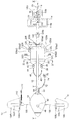
図1は、この実施例に係る水中スクータの平面図である。また、図2は、図1に示す水中スクータの左側面図であり、図3は、図1に示す水中スクータの正面図である。 FIG. 1 is a plan view of an underwater scooter according to this embodiment. 2 is a left side view of the underwater scooter shown in FIG. 1, and FIG. 3 is a front view of the underwater scooter shown in FIG.
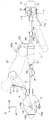
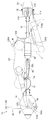
図1から図3において、符号10は水中スクータを示す。先ず、水中スクータ10の構成について概説すると、水中スクータ10は、円筒状に形成されてその長手方向が水中スクータ10の進行方向に対して平行となるように配置されたメインフレーム12と、メインフレーム12において進行方向前方に配置された卵型の水密(気密)容器14と、水密容器14の内部に収容された内燃機関(駆動源。図1から図3で図示せず。以下「エンジン」という)と、メインフレーム12において進行方向後方に配置され、エンジンで駆動されて回転して水中スクータ10を推進させるプロペラ16と、メインフレーム12の内部に挿通されてエンジンの出力をプロペラ16に伝達するドライブシャフト(図1から図3で図示せず)と、水密容器14の付近に配置されて水中スクータ10の航行深度の調整を行う深度調整機構18と、プロペラ16の付近に配置されて水中スクータ10の進行方向の調整を行う操舵機構20と、メインフレーム12において水密容器14とプロペラ16の間に配置された第1のエアタンク22と第2のエアタンク24を備える。
1 to 3,
次いで、上記した各構成について詳説する。 Next, each of the above-described configurations will be described in detail.
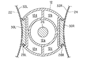
図4は、図1のIV−IV線拡大断面図である。図示の如く、メインフレーム12の内部は区画壁によって分割され、5つの通路が形成される。各通路は、メインフレーム12の先端から後端まで連続する1つの空間として形成される。5つの通路のうち、中心に位置する円筒状の第1の通路12aには、前記したドライブシャフト(符号26で示す)が挿通される。これに対し、第1の通路12aの外周を分割して形成された第2から第5の通路12b,12c,12d,12eは、後述の如く、空気や排出ガスの流路となる。
4 is an enlarged sectional view taken along line IV-IV in FIG. As illustrated, the interior of the
メインフレーム12の両側面には、断面視において略Cの字状(あるいはその左右対称の断面形状)を呈する溝部28L,28Rが形成される。図2に示すように、溝部28L(およびその裏面に位置する溝部28R)は、メインフレーム12の長手方向(進行方向)に所定の長さを有するように形成される。
On both side surfaces of the
図4の説明を続けると、左右の溝部28L,28Rには、それぞれ断面視において略Hの字状を呈するスライダ30L,30Rがスライド自在に嵌められる。即ち、スライダ30L,30Rは、溝部28L,28Rの上端と下端に形成された突起をレールとして、スライド自在に構成される。
If the explanation of FIG. 4 is continued,
スライダ30L,30Rには、それぞれベルト32L,32Rが設けられる。前記した第1のエアタンク22と第2のエアタンク24は、ベルト32L,32Rを介してそれぞれスライダ30L,30Rに装着される。これにより、第1のエアタンク22と第2のエアタンク24は、メインフレーム12の長手方向(即ち、水中スクータ10の進行方向)にスライド自在に装着される。
図1から図3の説明に戻ると、第1のエアタンク22は、バルブ36を介してレギュレータ38に接続される。レギュレータ38は、ホース40を介してメインフレーム12の内部(具体的には第2の通路12b)に接続される。一方、第2のエアタンク24は、バルブ42を介してレギュレータ44に接続される。レギュレータ44は、ホース46を介してメインフレーム12の内部(具体的には、第3の通路12c)に接続される。尚、第1および第2のエアタンク22,24の容積は、例えば12リットル程度であり、その内部には空気が高圧(例えば200気圧程度)に圧縮されて封入される。
Returning to the description of FIG. 1 to FIG. 3, the
第1のエアタンク22に封入された空気は、レギュレータ38で所定の圧力(例えば10気圧程度)まで減圧された後、ホース40を介してメインフレーム12の第2の通路12bに供給される。一方、第2のエアタンク24に封入された空気は、レギュレータ44で前記した所定の圧力(10気圧程度)まで減圧された後、ホース46を介してメインフレーム12の第3の通路12cに供給される。
The air sealed in the
図5は、図1のV−V線拡大断面図である。また、図6は、図2のVI−VI線拡大断面図である。 FIG. 5 is an enlarged sectional view taken along line VV in FIG. 6 is an enlarged sectional view taken along line VI-VI in FIG.
図5および図6に示すように、水密容器14は、進行方向前方からバンパー14a、燃料タンク14bおよびエンジン収容部14cの3つの部材から構成される。
As shown in FIGS. 5 and 6, the
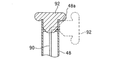
エンジン収容部14cには、エンジンEが収容される。エンジンEは、例えば排気量30cc程度の単気筒火花点火式ガソリンエンジンである。また、エンジン収容部14cの上部には、上方へと突出するシュノーケル48が設けられ、かかるシュノーケル48を介してエンジン収容部14cの内部と外部(大気)とが連通される。
The engine E is accommodated in the
エンジン収容部14cの前方には、ボルト50によって燃料タンク14bが取り付けられ、燃料タンク14bには、エンジンEに供給されるべきガソリン燃料が貯留される。また、燃料タンク14bの前面には給油口52が穿設され、給油口52は、キャップ54によって封止される。
A
燃料タンク14bの前方には、前記キャップ54を被覆するようにバンパー14aが取り付けられる。バンパー14aは、水中スクータ10が外部と衝突したときに変形して衝撃を緩和できるように、他の部材よりも硬度の小さい材料で形成される。また、バンパー14aは、燃料タンク14bへのガソリン燃料の供給を容易に行うことができるように、工具を使用することなく着脱自在とされる。
A
また、エンジン収容部14cの後方には、ボルト56によって接続部材60が取り付けられる。接続部材60は、メインフレーム12の直径と略同径の内径を有する円筒部60aを備える。
A
図7は、図5のVII−VII線拡大断面図である。図7に示すように、メインフレーム12の先端付近には、ナット62が収容される。図5から図7に示すように、接続部材60の円筒部60aにメインフレーム12の先端を挿入し、ちょうボルト64をナット62に螺合させることにより、メインフレーム12の前方に接続部材60を介して水密容器14が取り付けられる。尚、ナット62は、図7に示す如く周囲を区画壁で囲われ、その回転が抑止される。
7 is an enlarged sectional view taken along line VII-VII in FIG. As shown in FIG. 7, a
図5および図6の説明に戻ると、メインフレーム12の第2の通路12bは、接続部材60に形成された連通路60b(図6に示す)を介し、水密容器14内に配置されたレギュレータ68に接続される。また、第3の通路12cは、接続部材60の内部に形成された連通路(図示せず)と水密容器14内に設けられた流路70を介し、水密容器14の外部へと連続するホース72に接続される。ホース72の先端には、レギュレータ74が接続され、レギュレータ74には、さらにマウスピース76(いずれも図1および図2に示す)が接続される。
Returning to the description of FIGS. 5 and 6, the
また、メインフレーム12の第4の通路12dは、接続部材60に形成された連通路60cを介してエンジンEの排気管78に接続される。尚、図示は省略するが、第5の通路12eは、接続部材60に形成された連通路を介して水密容器14の内部と連通される。
Further, the
エンジンEは、図示しない吸気管を備える。吸気管の入口付近にはエアフィルタが設けられると共に、その下流にはスロットルボディ(いずれも図示せず)が配置される。スロットルボディにはスロットルバルブが収容されると共に、その上流側にはキャブレタ・アシー(いずれも図示せず)が設けられる。キャブレタ・アシーには燃料管80(図5に示す)が接続される。燃料管80は燃料タンク14bの内部に連通されると共に、その先端には燃料ポンプ82が接続される。
The engine E includes an intake pipe (not shown). An air filter is provided in the vicinity of the inlet of the intake pipe, and a throttle body (both not shown) is disposed downstream thereof. A throttle valve is accommodated in the throttle body, and a carburetor assembly (both not shown) is provided upstream of the throttle valve. A fuel pipe 80 (shown in FIG. 5) is connected to the carburetor assembly. The
また、エンジンEのクランクシャフトES(図5に示す)の一端には、遠心クラッチ84が接続される。遠心クラッチ84の出力側は減速機構86に接続され、減速機構86の出力側はドライブシャフト26の前端に接続される。尚、水中スクータ10にはエンジンEの回転数を調節する図示しないスロットル装置が設けられ、遠心クラッチ84は、エンジンEの回転数が上昇させられたときにその動力を伝達する。
A
一方、クランクシャフトESの他端には、リコイルスタータ88が取り付けられる。リコイルスタータ88のスタータロープ90は、シュノーケル48の内部に挿通されると共に、その先端にはスタータグリップ92が設けられる。スタータグリップ92は、シュノーケル48の上端に着脱自在に構成される。具体的には、スタータグリップ92は、シュノーケル48の上端にその開口部を水密に封止するように装着されると共に、前記上端から取り外し自在に構成される。即ち、エンジンEを始動させる際はシュノーケル48の上端からスタータグリップ92を取り外し、スタータロープ90を引き出す。エンジンEを始動した後は、シュノーケル48から水が浸入するのを防止すべく、シュノーケル48の上端にスタータグリップ92を取り付けてその開口部を封止する。
On the other hand, a
図8は、シュノーケル48の上端付近の拡大図であり、図9は図8のIX−IX線断面図である。図8および図9に示す如く、シュノーケル48の上端には、取り外したスタータグリップ92(図9に破線で示す)を係止すべき切り欠き部48aが設けられる。
8 is an enlarged view near the upper end of the
ここで、第1のエアタンク22から所定の圧力に減圧されてメインフレーム12の第2の通路12bに供給された空気は、連通路60bを介してレギュレータ68に供給されると共に、レギュレータ68で水密容器14の内圧まで減圧された後、水密容器14の内部(具体的にはエンジン収容部14c)に供給される。
Here, the air that has been decompressed to a predetermined pressure from the
水密容器14に供給された空気は、エアフィルタを介して吸気管に吸入される。キャブレタ・アシーは、吸入された空気にガソリン燃料を噴射して混合気を生成する。生成された混合気は、エンジンEの燃焼室(図示せず)に吸入されて燃焼させられる。混合気の燃焼によって生じた排出ガスは、排気管78および連通路60cを介してメインフレーム12の第4の通路12dに流入する。
The air supplied to the
一方、第2のエアタンク24から所定の圧力に減圧されてメインフレーム12の第3の通路12cに供給された空気は、前記した連通路と流路70、さらにはホース72を介してレギュレータ74に供給される。レギュレータ74は、図示しないダイヤフラムなどを備え、マウスピース76を咥えた操縦者(ダイバー)によって吸気動作が行われたとき、周囲の水圧まで減圧した空気を操縦者に供給する。
On the other hand, the air that has been depressurized from the
このように、水中スクータ10にあっては、メインフレーム12に第1のエアタンク22を取り付け、第1のエアタンク22に封入された空気をエンジンEの燃焼用の空気として供給するようにした。また、メインフレーム12に第2のエアタンク24を取り付け、第2のエアタンク24に封入された空気を操縦者の呼吸用の空気として供給するようにした。
As described above, in the
図10は、図1のX−X線拡大断面図である。 10 is an enlarged sectional view taken along line XX in FIG.
図10に示す如く、第1の通路12aに挿通されたドライブシャフト26の後端には、プロペラ16が取り付けられる。即ち、水中スクータ10は、メインフレーム12の前方に配置されたエンジンEの出力を前記した遠心クラッチ84、減速機構86およびメインフレーム12の内部に挿通されたドライブシャフト26を介してメインフレーム12の後方に配置されたプロペラ16に伝達し、よってプロペラ16を駆動して水上または水中を航行する。
As shown in FIG. 10, the
また、メインフレーム12の第4の通路12dの後端には、第1のワンウェイチェックバルブ94が配置される。第1のワンウェイチェックバルブ94は、排出ガスが第4の通路12dに流入してその内圧が所定の圧力を上回ったときに開弁し、第4の通路12dを外部(水中)に連通させる。即ち、エンジンEから排出された排出ガスは、排気管78、連通路60c、メインフレーム12の第4の通路12dおよび第1のワンウェイチェックバルブ94を介して水中スクータ10の後方(外部)へと排出される。
A first one-
さらに、メインフレーム12の第5の通路12eの後端には、第2のワンウェイチェックバルブ96が配置される。第2のワンウェイチェックバルブ96は、第5の通路12eの内圧(別言すれば、第5の通路12eに連通された水密容器14の内圧)が所定の圧力を上回ったときに開弁し、第5の通路12eを外部(水中)に連通させる。即ち、エンジンEの発熱などによって水密容器14の内圧が上昇すると、水密容器14内の空気が、接続部材60に形成された連通路、メインフレーム12の第5の通路12eおよび第2のワンウェイチェックバルブ96を介して水中スクータ10の後方(外部)へと排出され、よって水密容器14の内圧が調整(減圧)される。
Further, a second one-
上記の如く、メインフレーム12に形成された第1の通路12aは、ドライブシャフト26の挿通路となる。また、第2の通路12bは、エンジンEに供給されるべき燃焼用空気の流路となり、第3の通路12cは、操縦者に供給されるべき呼吸用空気の流路となる。さらに、第4の通路12dは、エンジンEから排出された排出ガスの流路となり、第5の通路12eは、水密容器14内の空気を外部に排出してその内圧を調整するための連通路となる。
As described above, the
尚、図示は省略するが、第2の通路12bと第3の通路12cは、メインフレーム12の後端において封止される。第2の通路12bと第3の通路12cをメインフレーム12の後端で封止するのは、メインフレーム12の前端から後端に空気を充満させ、メインフレーム12全体に均等な浮力を与えるためである。第4の通路12dと第5の通路12eにおいて各ワンウェイチェックバルブをそれらの後端に配置したのも、同様な理由からである。
Although not shown, the
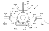
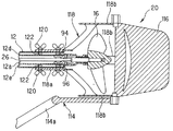
図1から図3の説明に戻ると、水密容器14には、水中スクータ10を潜行あるいは浮上させて航行深度を調整する深度調整機構18が取り付けられる。深度調整機構18は、バー100と、円筒状の左右のグリップ102L,102Rと、上面視略台形のプレートからなる左右のエレベータ104L,104Rと、グリップ102L,102Rをエレベータ104L,104Rに接続する接続部材106L,106Rとからなる。
Returning to the description of FIG. 1 to FIG. 3, the
深度調整機構18について具体的に説明すると、バー100は水密容器14に取り付けられ、その長手方向が水中スクータ10の左右方向に対して平行となるように配置される。バー100において進行方向に向かって左側の端部には、左グリップ102Lが取り付けられる。同様に、バー100において進行方向に向かって右側の端部には、右グリップ102Rが取り付けられる。尚、左右のグリップ102L,102Rは、それぞれバー100を中心として回転(具体的には自転)自在に取り付けられる。
The
左右のグリップ102L,102Rには、それぞれ接続部材106L,106Rを介してエレベータ104L,104Rが接続される。これにより、エレベータ104L,104Rは、水中スクータ10の左右軸回りに揺動自在とされる。即ち、グリップ102L,102Rを回転させることにより、エレベータ104L,104Rの左右軸回りの傾きの大きさと方向を変更することができ、よってエレベータ104L,104Rに作用する揚力(水中スクータ10を潜行あるいは浮上させる力)を調整することができる。
また、バー100の適宜位置には、エマージェンシスイッチ110が設けられる。エマージェンシスイッチ110には、そのオン、オフのトリガーとなるエマージェンシコード112(図1および図3に示す)の一端が取り付けられる。エマージェンシコード112の他端は、後述する如く、操縦者の腕に取り付けられる。
Further, an
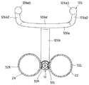
一方、メインフレーム12の後端には、操舵機構20が取り付けられる。操舵機構20は、フットスタンド114と、フットスタンド114に接続されたラダー116と、それらをメインフレーム12の後端に接続する接続部材118とからなる。
On the other hand, a
操舵機構20について具体的に説明すると、接続部材118は、メインフレーム12の直径と略同径の内径を有する円筒部118aを備える。図10に良く示すように、かかる円筒部118aにメインフレーム12の後端を挿入し、ちょうボルト120をメインフレーム12の内部に収容されたナット122に螺合させることにより、メインフレーム12に接続部材118、別言すれば、操舵機構20が取り付けられる。尚、図示は省略するが、ナット122も前述のナット62と同様に周囲を区画壁で囲われ、その回転が抑止される。
The
接続部材118は、前記円筒部118aに連続する上下左右の計4枚の翼部118bを備える。翼部118bは、プロペラ16との接触を上下方向あるいは左右方向に回避するように形成されると共に、それらの後端は、プロペラ16よりも後方に位置させられる。上記したフットスタンド114とそれに接続されたラダー116は、翼部118bの中、上下に配置された2枚の翼部の後端に上下軸回りに揺動自在に支持される。即ち、フットスタンド114を操作する(上下軸回りに回転させる)ことにより、ラダー116を上下軸回りに揺動させることができ、よって水中スクータ10の進行方向を調整することができる。
The connecting
また、図1から図3に示すように、第1および第2のエアタンク22,24の後端付近には、ウェストホルダ126が取り付けられる。
As shown in FIGS. 1 to 3, a
図11は、図1のXI−XI線拡大断面図である。図11に示すように、ウェストホルダ126は、具体的には左右のスライダ30L,30Rに取り付けられる。これにより、ウェストホルダ126は、第1および第2のエアタンク22,24と共に水中スクータ10の進行方向にスライド自在とされる。
11 is an enlarged sectional view taken along line XI-XI in FIG. As shown in FIG. 11, the
図1から図3および図11を参照してウェストホルダ126の形状について具体的に説明すると、図示の如く、ウェストホルダ126は、操縦者の腰部を支持する支持部126aと、支持部126aを左右のスライダ30L,30Rに接続する接続部126bとからなる。
The shape of the
支持部126aは、円柱部材を湾曲あるいは屈曲させて形成される。具体的には、支持部126aは、進行方向後方が凸状となるように湾曲させられた第1の部位(図1および図11において符号126a1で示す)と、前記第1の部位126a1の長手方向が図示のように水中スクータ10の左右方向と平行になるように配置されたとき、その左右両側を進行方向前方に所定の角度だけ上方を向いて突出するように屈曲させて形成された第2の部位(図1および図11において符号126a2で示す)とを備える。また、支持部126aにおいて前記第2の部位の先端(図1および図11において符号126a3で示す)は、球形あるいは略球形に形成される。
The
接続部126bは、柱状に(その長手方向が上下方向に平行となるように)形成され、その上端は支持部126aの中央(長手方向における中央)に接続される一方、下端は左右のスライダ30L,30Rの後端付近に取り付けられる。これにより、支持部126aは、第1および第2のエアタンク22,24の後端付近上方に配置される。
The connecting
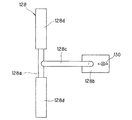
図1から図3の説明を続けると、メインフレーム12には、さらにフットホルダ128が取り付けられる。
Continuing the description of FIGS. 1 to 3, a
図12は、フットホルダ128の底面図である。図1から図3および図12を参照してフットホルダ128について具体的に説明すると、フットホルダ128は、操縦者の脚部を支持する支持部128aと、メインフレーム12に取り付けられる円筒部128bと、支持部128aを円筒部128bに接続する接続部128cとからなる。円筒部128bは、その内径がメインフレーム12の直径と略同径となるように形成される。
FIG. 12 is a bottom view of the
図示の如く、円筒部128bは、メインフレーム12において前記した左右の溝部28L,28Rよりも後方に取り付けられる。メインフレーム12への円筒部128bの取り付けは、円筒部128bにメインフレーム12を挿通し、ちょうボルト130をメインフレーム12の内部に収容されたナットに螺合させることによって行われる。尚、図示は省略するが、ちょうボルト130が螺合されるべきナットも、前述のナット62と同様に周囲を区画壁で囲われ、その回転が抑止される。
As shown in the figure, the
接続部128cは円柱部材からなり、図示のようにその一端が円筒部128bの下部に接続されたとき、他端が前記左右の溝部28L,28Rの下方、換言すれば、第1および第2のエアタンク22,24ならびにウェストホルダ126の下方に位置するように形成される。
The connecting
支持部128aは、その長手方向が水中スクータ10の左右方向と平行に配置されると共に、中央(長手方向における中央)に前記接続部128cの他端が接続される。即ち、支持部128aは、第1および第2のエアタンク22,24ならびにウェストホルダ126の下方において、その長手方向が水中スクータ10の左右方向に平行となるように配置される。尚、支持部128aは、その中央付近を除いてゴムなどの緩衝材(図12に符号128dで示す)で覆われる。
The
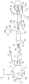
図13は、水中スクータ10と、それに騎乗した操縦者を示す左側面図である。
FIG. 13 is a left side view showing the
図13に示すように、操縦者OPは、第1のエアタンク22と第2のエアタンク24の上に騎乗する。具体的には、操縦者OPは、メインフレーム12を跨ぐようにして第1のエアタンク22と第2のエアタンク24に着座する。そして、前傾姿勢をとって前方に位置する左右のグリップ102L,102Rを把持すると共に、後方に位置するフットスタンド114の載置部114aに足を載置する、具体的には、足の甲を係止させる。尚、載置部114aは、図1に示すように、平面視において環状を呈する。
As shown in FIG. 13, the pilot OP rides on the
このとき、操縦者OPの腰部Wは、ウェストホルダ126の支持部126aに支持される。具体的には、腰部Wの後方と側方が、支持部126aに囲まれるようにして(より具体的には、前記した支持部126aの第1の部位126a1が腰部Wに後方に当接すると共に、第2の部位126a2が腰部Wの側方に当接して)支持される。また、操縦者OPの脚部F、具体的にはその膝裏付近は、フットホルダ128の支持部128aに当接して支持される。
At this time, the waist part W of the pilot OP is supported by the
また、操縦者OPの腕には、前述したエマージェンシコード112(図13で図示省略)の他端が装着される。これにより、操縦者OPが水中スクータ10から離脱したときにエマージェンシコード112の一端がエマージェンシスイッチ110から引き抜かれ、緊急停止信号が送出されてエンジンEが停止させられる。
Further, the other end of the emergency cord 112 (not shown in FIG. 13) is attached to the arm of the operator OP. As a result, when the operator OP leaves the
次いで、操縦者OPによる水中スクータ10の操縦、具体的には、航行深度と進行方向の調整について説明する。
Next, the operation of the
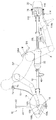
先ず、水中スクータ10を潜行させるときは、図14に示す如く、左右のエレベータ104L,104Rの前端を後端よりも下方に位置させるように左右のグリップ102L,102Rを回転させる。この状態で水中スクータ10を前進させることにより、左右のエレベータ104L,104Rには下向きの力が作用し、よって水中スクータ10が潜行させられる。また、このとき、操縦者OPは騎乗部たる第1および第2のエアタンク22,24を後方へとスライドさせる。即ち、第1および第2のエアタンク22,24の浮力が作用する位置を後方へと移動させる。これにより、水中スクータ10の後方の浮力が大きくなり、水中スクータ10の前方が沈み込む(後方が浮き上がる)ことから、潜行に適した(潜行し易い)姿勢となる。
First, when the
これに対し、水中スクータ10を浮上させるときは、図15に示す如く、左右のエレベータ104L,104Rの前端を後端よりも上方に位置させるように左右のグリップ102L,102Rを回転させる。この状態で水中スクータ10を前進させることにより、左右のエレベータ104L,104Rには上向きの力が作用し、よって水中スクータ10が浮上させられる。また、このとき、操縦者OPは騎乗部たる第1および第2のエアタンク22,24を前方へとスライドさせる。即ち、第1および第2のエアタンク22,24の浮力が作用する位置を前方へと移動させる。これにより、水中スクータ10の前方の浮力が大きくなり、水中スクータ10の前方が浮き上がる(後方が沈み込む)ことから、浮上に適した(浮上し易い)姿勢となる。
On the other hand, when the
一方、水中スクータ10の進行方向を調整するときは、フットスタンド114に載置した足でフットスタンド114を左右に操作し、よってラダー116を上下軸回りに揺動させる。これにより、水中スクータ10が左右に操舵される。
On the other hand, when the traveling direction of the
このように、この実施例に係る水中スクータ10にあっては、円筒状に形成されたメインフレーム12の前方にエンジンEを収容する水密容器14を配置する一方、後方にプロペラ16を配置し、メインフレーム12の内部に挿通されたドライブシャフト26でエンジンEの出力をプロペラ16に伝達すると共に、メインフレーム12においてエンジンEとプロペラ16の間に配置された第1および第2のエアタンク22,24に操縦者OPが騎乗するようにしたので、操縦者を牽引するタイプの従来例に比して操縦者の負担を軽減させることができる。
Thus, in the
また、プロペラ16が操縦者OPよりも後方に配置されると共に、エンジンEの排出ガスがメインフレーム12の第4の通路12dを通過して操縦者OPの後方に排出されることから、プロペラ16から噴出された水流やエンジンEの排出ガスによって操縦者の視界が低下するおそれがない。さらに、プロペラ16から噴出された水流やエンジンEの排出ガスによって操縦者OPの装着物(ゴーグルなど)が脱落するおそれもない。
In addition, the
また、第1のエアタンク22に封入された空気をエンジンEの燃焼用空気として供給すると共に、第2のエアタンク24に封入された空気を操縦者OPの呼吸用空気として供給するようにしたので、水上および水中での航行が可能になると共に、操縦者の快適性を向上させることができる。
In addition, the air sealed in the
また、第1および第2のエアタンク22,24に操縦者OPの腰部Wを支持するウェストホルダ126を取り付けるようにしたので、操縦者の姿勢を安定させることができ、よって操縦者の負担を一層軽減させることができる。
Further, since the
また、騎乗部たる第1および第2のエアタンク22,24が、メインフレーム12に進行方向においてスライド自在に装着されるようにしたので、操縦者の体格や姿勢に応じてその位置を最適に調整することができ、よって操縦者の負担をより効果的に軽減させることができる。さらに、ウェストホルダ126も各エアタンク22,24と共にスライドすることから、操縦者の体格や姿勢に応じて第1および第2のエアタンク22,24の位置を最適に調整することで、ウェストホルダ126による腰部Wの支持も確実となって姿勢をより安定させることができ、よって操縦者の負担をより一層軽減させることができる。
In addition, the first and
また、メインフレーム12に操縦者OPの脚部Fを支持するフットホルダ128を取り付けるようにしたので、操縦者の姿勢をより一層安定させることができ、よって操縦者の負担をより一層軽減させることができる。
In addition, since the
また、ウェストホルダ126の支持部126aの第3の部位126a3(進行方向前方に突出した第2の部位126a2の先端)を球形あるいは略球形に形成すると共に、フットホルダ128を緩衝材128dで覆うようにしたので、操縦者の快適性を向上させることができる。尚、ウェストホルダ126の支持部126aも緩衝材で覆うようにしても良い。
Further, the third portion 126a3 (the tip of the second portion 126a2 protruding forward in the traveling direction) of the
また、第1および第2のエアタンク22,24を水中スクータ10の進行方向にスライド自在とし、それらの浮力が作用する位置を可変としたことから、水中スクータ10を潜行または浮上に適した姿勢にすることができ、よって水中スクータ10の深度調整を容易に行うことができる。
In addition, since the first and
また、遠心クラッチ84を介してエンジンEの出力をプロペラ16に伝達するようにしたので、エンジンEの運転を停止することなく水中スクータ10の航行を停止することができる。
Moreover, since the output of the engine E is transmitted to the
以上の如く、この発明の第1実施例にあっては、操縦者(OP)に操縦されて水上または水中を航行する水中スクータ(10)において、メインフレーム(12)と、前記メインフレーム(12)の前記水中スクータ(10)の進行方向において前方に配置された水密容器(14)と、前記水密容器(14)に収容された駆動源(エンジンE)と、前記メインフレーム(12)の前記進行方向において後方に配置され、前記駆動源(E)によって駆動されて回転して前記水中スクータ(10)を推進させるプロペラ(16)と、前記メインフレーム(12)において前記水密容器(14)と前記プロペラ(16)の間に配置された前記操縦者(OP)が騎乗すべき騎乗部(第1のエアタンク22、第2のエアタンク24)と、前記騎乗部(22,24)に取り付けられて前記操縦者(OP)の腰部(W)を支持するウェストホルダ(126)とを備えるように構成した。
As described above, in the first embodiment of the present invention, the main frame (12) and the main frame (12) in the underwater scooter (10) that is operated by the operator (OP) and sails on or under water. ) Of the underwater scooter (10) in the traveling direction of the watertight container (14), the drive source (engine E) accommodated in the watertight container (14), and the main frame (12) A propeller (16) disposed rearward in the traveling direction and driven and rotated by the drive source (E) to propel the underwater scooter (10); and the watertight container (14) in the main frame (12) A riding section (
また、前記騎乗部(22,24)が、前記メインフレーム(12)に前記進行方向においてスライド自在に装着されるように構成した。 Further, the riding section (22, 24) is configured to be slidably mounted on the main frame (12) in the traveling direction.
また、前記メインフレーム(12)に取り付けられて前記操縦者(OP)の脚部(F)を支持するフットホルダ(128)を備えるように構成した。 Moreover, it comprised so that the foot holder (128) attached to the said main frame (12) and supporting the leg part (F) of the said operator (OP) might be provided.
尚、上記において、プロペラ16を駆動する駆動源をエンジンEとしたが、電動モータなどであっても良い。
In the above description, the drive source for driving the
また、ウェストホルダ126を、円柱部材を湾曲あるいは屈曲させて形成したが、それに限られるものではなく、例えばバックレスト(背もたれ)型などであっても良い。フットホルダ128の形状も、同様に上記に限られるものではない。
The
また、水中スクータ10が水上あるいは水面付近を航行するとき(即ち、航行深度が浅く、シュノーケル48の上端が水面より上方に位置するとき)は、シュノーケル48の上端からスタータグリップ92を取り外して前記切り欠き部48aに係止させる(即ち、開口部を封止しないようにする)ことで、外気をエンジンEの燃焼用空気として取り入れるようにしても良い。このとき、第1のエアタンク22に接続されたバルブ36を閉弁し、第1のエアタンク22からの空気の供給を停止することで、タンク内に封入された空気の消費量を低減することができる。
Further, when the
さらに、シュノーケル48とマウスピース76を接続し、水中スクータ10が水上を航行するときは操縦者の呼吸用空気も外部から導入するようにしても良い。このとき、第2のエアタンク24に接続されたバルブ42を閉弁し、第2のエアタンク24からの空気の供給を停止することで、同様に封入された空気の消費量を低減することができる。
Further, the
また、水密容器14の内圧が上昇したとき、水密容器14内の空気をメインフレーム12の第5の通路12eと第2のワンウェイチェックバルブ96を介して外部に排出するようにしたが、前記スタータグリップ92にワンウェイチェックバルブを設け、そこから水密容器14内の空気を外部に排出するようにしても良い。
Further, when the internal pressure of the
10 水中スクータ
12 メインフレーム
14 水密容器
16 プロペラ
22 第1のエアタンク(騎乗部)
24 第2のエアタンク(騎乗部)
126 ウェストホルダ
128 フットホルダ
E エンジン(駆動源)
10
24 2nd air tank (sitting part)
126
Claims (3)
The underwater scooter according to claim 1, further comprising a foot holder attached to the main frame and supporting a leg portion of the operator.
Priority Applications (2)
| Application Number | Priority Date | Filing Date | Title |
|---|---|---|---|
| JP2004116154A JP2005297740A (en) | 2004-04-09 | 2004-04-09 | Underwater scooter |
| US11/102,163 US7011035B2 (en) | 2004-04-09 | 2005-04-08 | Underwater scooter |
Applications Claiming Priority (1)
| Application Number | Priority Date | Filing Date | Title |
|---|---|---|---|
| JP2004116154A JP2005297740A (en) | 2004-04-09 | 2004-04-09 | Underwater scooter |
Publications (1)
| Publication Number | Publication Date |
|---|---|
| JP2005297740A true JP2005297740A (en) | 2005-10-27 |
Family
ID=35329814
Family Applications (1)
| Application Number | Title | Priority Date | Filing Date |
|---|---|---|---|
| JP2004116154A Withdrawn JP2005297740A (en) | 2004-04-09 | 2004-04-09 | Underwater scooter |
Country Status (1)
| Country | Link |
|---|---|
| JP (1) | JP2005297740A (en) |
-
2004
- 2004-04-09 JP JP2004116154A patent/JP2005297740A/en not_active Withdrawn
Similar Documents
| Publication | Publication Date | Title |
|---|---|---|
| US5586922A (en) | Watercraft | |
| US7736207B2 (en) | Marine outboard engine having a padded section | |
| JP3662590B2 (en) | Water jet powered watercraft | |
| JP4219848B2 (en) | Underwater scooter | |
| WO2016144852A1 (en) | Modular personal watercraft hull, steering, control, and seating systems | |
| JP3960681B2 (en) | Hull structure of a straddled boat | |
| JP4219845B2 (en) | Underwater scooter | |
| JP4219847B2 (en) | Underwater scooter | |
| JP2005297740A (en) | Underwater scooter | |
| JP4219849B2 (en) | Underwater scooter | |
| JP2005297738A (en) | Underwater scooter | |
| JP4219846B2 (en) | Underwater scooter | |
| JP2005297745A (en) | Underwater scooter | |
| JP2005297739A (en) | Underwater scooter | |
| JP2005297744A (en) | Underwater scooter | |
| US7011035B2 (en) | Underwater scooter | |
| US7096815B2 (en) | Underwater scooter | |
| KR101219625B1 (en) | Water scooter | |
| JPH0657555B2 (en) | Small water vehicle | |
| JP2837539B2 (en) | Small boat | |
| US6872105B2 (en) | Watercraft having a jet propulsion system with improved efficiency | |
| JP2005297746A (en) | Underwater scooter | |
| US7527007B2 (en) | Personal watercraft | |
| JP2688459B2 (en) | Small watercraft | |
| JP3904660B2 (en) | Saddle-type small vessel |
Legal Events
| Date | Code | Title | Description |
|---|---|---|---|
| A300 | Withdrawal of application because of no request for examination |
Free format text: JAPANESE INTERMEDIATE CODE: A300 Effective date: 20070703 |