JP2005297738A - Underwater scooter - Google Patents

Underwater scooter Download PDF

Info

Publication number
JP2005297738A
JP2005297738A JP2004116152A JP2004116152A JP2005297738A JP 2005297738 A JP2005297738 A JP 2005297738A JP 2004116152 A JP2004116152 A JP 2004116152A JP 2004116152 A JP2004116152 A JP 2004116152A JP 2005297738 A JP2005297738 A JP 2005297738A
Authority
JP
Japan
Prior art keywords
air
underwater scooter
air tank
underwater
watertight container
Prior art date
Legal status (The legal status is an assumption and is not a legal conclusion. Google has not performed a legal analysis and makes no representation as to the accuracy of the status listed.)
Withdrawn
Application number
JP2004116152A
Other languages
Japanese (ja)
Inventor
Yoshihiro Iijima
良洋 飯嶋
Hiroshi Sueshige
洋 末繁
Keiji Iino
啓司 飯野
Masayuki Osumi
雅之 大角
Hiroaki Hasebe
博昭 長谷部
Current Assignee (The listed assignees may be inaccurate. Google has not performed a legal analysis and makes no representation or warranty as to the accuracy of the list.)
Honda Motor Co Ltd
Original Assignee
Honda Motor Co Ltd
Priority date (The priority date is an assumption and is not a legal conclusion. Google has not performed a legal analysis and makes no representation as to the accuracy of the date listed.)
Filing date
Publication date
Application filed by Honda Motor Co Ltd filed Critical Honda Motor Co Ltd
Priority to JP2004116152A priority Critical patent/JP2005297738A/en
Priority to US11/102,163 priority patent/US7011035B2/en
Publication of JP2005297738A publication Critical patent/JP2005297738A/en
Withdrawn legal-status Critical Current

Links

Images

Landscapes

  • Fire-Extinguishing By Fire Departments, And Fire-Extinguishing Equipment And Control Thereof (AREA)

Abstract

<P>PROBLEM TO BE SOLVED: To provide an underwater scooter capable of realizing on-water navigation and underwater navigation by driving a propeller by an internal combustion engine. <P>SOLUTION: The underwater scooter has a snorkel (48) to communicate the inside of a watertight container (14) to store an engine with the atmosphere, and an air tank (22) in which air to be fed to the inside of the watertight container (14) is sealed. When the underwater scooter (10) is navigating on water, air for combustion is fed to the engine from either the snorkel (48) or the air tank (22). On the other hand, when the underwater scooter (10) is navigating underwater, air for combustion is fed from the air tank (22). A starter grip (92) is attached to an upper end of the snorkel (48) to prevent ingress of water into the watertight container (14). <P>COPYRIGHT: (C)2006,JPO&NCIPI

Description

この発明は、水上または水中を航行する水中スクータに関する。   The present invention relates to an underwater scooter that sails on water or underwater.

従来、例えば特許文献1に記載されるように、操縦者(ダイバー)に操縦されて水上または水中を航行する水中スクータが提案されている。特許文献1に記載される水中スクータにあっては、電動モータでプロペラを駆動することによって推進力を得るようにしている。そして、操縦者が把持すべきグリップを備え、かかるグリップを把持した操縦者を牽引することにより、その進行を補助するように構成している。
特公平4−17832号公報
2. Description of the Related Art Conventionally, as described in Patent Document 1, for example, an underwater scooter that is operated by a driver (diver) and sails on or under water has been proposed. In the underwater scooter described in Patent Document 1, propulsion is obtained by driving a propeller with an electric motor. The pilot is provided with a grip to be gripped, and is configured to assist the advancement by pulling the pilot holding the grip.
Japanese Patent Publication No. 4-17832

また、例えば特許文献2に記載される技術にあっては、内燃機関でプロペラを駆動することによって推進力を得るように構成している。ここで、前記内燃機関に供給すべき燃焼用の空気は、水中スクータの上面に配置された吸気口(air inlet 50)から導入される。
米国特許第5,394,820号明細書(第4欄、図3など)
Further, for example, the technique described in Patent Document 2 is configured to obtain a propulsive force by driving a propeller with an internal combustion engine. Here, the combustion air to be supplied to the internal combustion engine is introduced from an air inlet (air inlet 50) disposed on the upper surface of the underwater scooter.
US Pat. No. 5,394,820 (column 4, FIG. 3, etc.)

上記特許文献2に記載される技術にあっては、内燃機関に供給すべき空気を水中スクータの上面に配置された吸気口から導入しているため、吸気口が冠水しない水上しか航行できないという問題があった。   In the technique described in Patent Document 2, since air to be supplied to the internal combustion engine is introduced from an intake port disposed on the upper surface of the underwater scooter, the problem is that the intake port can only travel on water that is not flooded. was there.

従って、この発明の目的は上記した課題を解決することにあり、内燃機関でプロペラを駆動して水上と水中の両方を航行できるようにした水中スクータを提供することにある。   Accordingly, an object of the present invention is to solve the above-described problems, and to provide an underwater scooter that can drive both a water surface and an underwater by driving a propeller with an internal combustion engine.

上記した課題を解決するために、請求項1にあっては、操縦者に操縦されて水上または水中を航行する水中スクータにおいて、前記操縦者が騎乗すべきメインフレームと、前記メインフレームに配置された水密容器と、前記水密容器に収容された内燃機関と、前記内燃機関によって駆動されて回転して前記水中スクータを推進させるプロペラと、前記水密容器の内部を大気に連通させるシュノーケルと、前記水密容器の内部に供給されるべき空気が封入された第1のエアタンクとを備えると共に、前記シュノーケルおよび前記第1のエアタンクの少なくともいずれかから前記内燃機関に燃焼用空気を供給するように構成した。   In order to solve the above-described problems, in claim 1, in an underwater scooter that is operated by a pilot and sails on or under water, the main frame to be mounted by the pilot is disposed on the main frame. A watertight container, an internal combustion engine accommodated in the watertight container, a propeller driven by the internal combustion engine to propel the underwater scooter, a snorkel that communicates the interior of the watertight container to the atmosphere, and the watertight A first air tank in which air to be supplied into the container is enclosed, and combustion air is supplied from at least one of the snorkel and the first air tank to the internal combustion engine.

また、請求項2にあっては、前記第1のエアタンクに封入された空気を前記操縦者に供給すべく供給先を変更する第1の空気供給先変更手段を備えるように構成した。   According to a second aspect of the present invention, there is provided a first air supply destination changing means for changing a supply destination so as to supply the air enclosed in the first air tank to the operator.

また、請求項3にあっては、前記第1のエアタンクが、前記メインフレームに前記水中スクータの進行方向においてスライド自在に装着されるように構成した。   According to a third aspect of the present invention, the first air tank is slidably mounted on the main frame in the traveling direction of the underwater scooter.

また、請求項4にあっては、前記第1のエアタンクの空気残量を検出して表示する第1の空気残量表示手段を備えるように構成した。   According to a fourth aspect of the present invention, the first air remaining amount display means for detecting and displaying the remaining amount of air in the first air tank is provided.

また、請求項5にあっては、前記内燃機関を始動するリコイルスタータを備えると共に、前記リコイルスタータのグリップによって前記シュノーケルの開口部を封止するように構成した。   According to a fifth aspect of the present invention, a recoil starter for starting the internal combustion engine is provided, and an opening of the snorkel is sealed by a grip of the recoil starter.

また、請求項6にあっては、前記リコイルスタータのグリップに、前記水密容器の内圧が所定の圧力を上回ったときに開弁して前記水密容器を外部に連通させるワンウェイチェックバルブを配置するように構成した。   According to a sixth aspect of the present invention, a one-way check valve is arranged on the grip of the recoil starter to open when the internal pressure of the watertight container exceeds a predetermined pressure and to communicate the watertight container to the outside. Configured.

また、請求項7にあっては、前記操縦者に供給されるべき空気が封入された第2のエアタンクを備えるように構成した。   According to a seventh aspect of the present invention, there is provided a second air tank in which air to be supplied to the pilot is enclosed.

また、請求項8にあっては、前記第2のエアタンクに封入された空気を前記水密容器の内部に供給すべく供給先を変更する第2の空気供給先変更手段を備えるように構成した。   Further, according to the eighth aspect of the present invention, there is provided a second air supply destination changing means for changing the supply destination so as to supply the air sealed in the second air tank to the inside of the watertight container.

また、請求項9にあっては、前記第2のエアタンクが、前記メインフレームに前記水中スクータの進行方向においてスライド自在に装着されるように構成した。   According to a ninth aspect of the present invention, the second air tank is slidably mounted on the main frame in the traveling direction of the underwater scooter.

また、請求項10にあっては、前記第2のエアタンクの空気残量を検出して表示する第2の空気残量表示手段を備えるように構成した。   Further, according to a tenth aspect of the present invention, a second air remaining amount display means for detecting and displaying the remaining amount of air in the second air tank is provided.

請求項1に係る水中スクータにあっては、操縦者が騎乗すべきメインフレームと、前記メインフレームに配置された水密容器と、前記水密容器に収容された内燃機関と、前記内燃機関によって駆動されて回転して前記水中スクータを推進させるプロペラと、前記水密容器の内部を大気に連通させるシュノーケルと、前記水密容器の内部に供給されるべき空気が封入された第1のエアタンクとを備えると共に、前記シュノーケルおよび前記第1のエアタンクの少なくともいずれかから前記内燃機関に燃焼用空気を供給するように構成したので、内燃機関でプロペラを駆動して水上と水中の両方を航行することができる。   The underwater scooter according to claim 1 is driven by the main frame on which the operator should ride, a watertight container disposed in the main frame, an internal combustion engine accommodated in the watertight container, and the internal combustion engine. A propeller that rotates to propel the underwater scooter, a snorkel that allows the inside of the watertight container to communicate with the atmosphere, and a first air tank that is filled with air to be supplied to the inside of the watertight container, Since the combustion air is supplied from at least one of the snorkel and the first air tank to the internal combustion engine, the propeller is driven by the internal combustion engine, and both the surface and the water can be navigated.

また、請求項2に係る水中スクータにあっては、前記第1のエアタンクに封入された空気を前記操縦者に供給すべく供給先を変更する第1の空気供給先変更手段を備えるように構成したので、上記した効果に加え、内燃機関の停止時や水中スクータの航行深度が浅くシュノーケルから燃焼用空気が導入できる場合、第1のエアタンクに封入された空気を操縦者に呼吸用の空気として供給することができ、よって操縦者の快適性を向上させることができる。   The underwater scooter according to claim 2 includes a first air supply destination changing unit that changes a supply destination so as to supply the air enclosed in the first air tank to the operator. Therefore, in addition to the above-described effects, when the combustion air can be introduced from the snorkel when the internal combustion engine is stopped or the underwater scooter is shallow, the air enclosed in the first air tank is used as breathing air for the operator. Therefore, the comfort of the operator can be improved.

また、請求項3に係る水中スクータにあっては、前記第1のエアタンクが、前記メインフレームに前記水中スクータの進行方向においてスライド自在に装着されるように構成したので、第1のエアタンクの浮力が作用する位置を変更することができる。このため、上記した効果に加え、水中スクータの姿勢を潜行または浮上に適した姿勢に変更することができ、よって水中スクータの深度調整を容易に行うことができる。   In the underwater scooter according to claim 3, the first air tank is configured to be slidably mounted on the main frame in the traveling direction of the underwater scooter. It is possible to change the position where the action acts. For this reason, in addition to the effects described above, the posture of the underwater scooter can be changed to a posture suitable for submergence or ascent, and therefore the depth adjustment of the underwater scooter can be easily performed.

また、請求項4に係る水中スクータにあっては、前記第1のエアタンクの空気残量を検出して表示する第1の空気残量表示手段を備えるように構成したので、上記した効果に加え、水中スクータの潜行可能時間(距離)を報知することができる。   In addition, the underwater scooter according to claim 4 is configured to include first remaining air amount display means for detecting and displaying the remaining amount of air in the first air tank. The submersible time (distance) of the underwater scooter can be notified.

また、請求項5に係る水中スクータにあっては、前記内燃機関を始動するリコイルスタータを備えると共に、前記リコイルスタータのグリップによって前記シュノーケルの開口部を封止するように構成したので、上記した効果に加え、水密容器に収容された内燃機関の始動を容易に行うことができると共に、水中スクータが潜行しているときにシュノーケルから水密容器の内部に水が浸入するのを防止することができる。   The underwater scooter according to claim 5 is provided with a recoil starter for starting the internal combustion engine, and the opening of the snorkel is sealed by a grip of the recoil starter. In addition, the internal combustion engine housed in the watertight container can be easily started, and water can be prevented from entering the inside of the watertight container from the snorkel when the underwater scooter is submerged.

また、請求項6に係る水中スクータにあっては、前記リコイルスタータのグリップに、前記水密容器の内圧が所定の圧力を上回ったときに開弁して前記水密容器を外部に連通させるワンウェイチェックバルブを配置するように構成したので、上記した効果に加え、内燃機関の発熱などによって水密容器の内圧が上昇したとき、リコイルスタータのグリップに配置されたワンウェイチェックバルブを介して水密容器内の空気を外部に排出する(水密容器の内圧を減圧する)ことができる。   In the underwater scooter according to claim 6, the one-way check valve that opens the grip of the recoil starter when the internal pressure of the watertight container exceeds a predetermined pressure to communicate the watertight container to the outside. In addition to the effects described above, when the internal pressure of the watertight container rises due to heat generated by the internal combustion engine, etc., the air in the watertight container is removed via the one-way check valve disposed on the grip of the recoil starter. It is possible to discharge to the outside (reducing the internal pressure of the watertight container).

また、請求項7に係る水中スクータにあっては、前記操縦者に供給されるべき空気が封入された第2のエアタンクを備えるように構成したので、上記した効果に加え、内燃機関への燃焼用空気の供給と操縦者への呼吸用空気の供給を同時に行うことができ、よって操縦者の快適性をより向上させることができる。   In addition, the underwater scooter according to claim 7 is configured to include the second air tank in which the air to be supplied to the operator is enclosed, so that in addition to the above-described effects, the combustion to the internal combustion engine The supply of working air and the supply of breathing air to the pilot can be performed at the same time, so that the comfort of the pilot can be further improved.

また、請求項8に係る水中スクータにあっては、前記第2のエアタンクに封入された空気を前記水密容器の内部に供給すべく供給先を変更する第2の空気供給先変更手段を備えるように構成したので、上記した効果に加え、水中スクータの潜行可能時間(距離)を延長することができる。また、前記した第1の空気供給先変更手段と第2の空気供給先変更手段の両方を備える場合には、燃焼用空気と呼吸用空気の消費量に差が生じても、各エアタンクに封入された空気を効率良く使用することができる。   The underwater scooter according to claim 8 further includes second air supply destination changing means for changing the supply destination so as to supply the air sealed in the second air tank to the inside of the watertight container. Therefore, in addition to the effects described above, the underwater scooter can be submerged (distance) can be extended. Further, when both the first air supply destination changing means and the second air supply destination changing means are provided, even if there is a difference in the consumption of combustion air and breathing air, the air tanks are sealed. The used air can be used efficiently.

また、請求項9に係る水中スクータにあっては、前記第2のエアタンクが、前記メインフレームに前記水中スクータの進行方向においてスライド自在に装着されるように構成したので、上記した効果に加え、第2のエアタンクの浮力が作用する位置を変更して水中スクータを潜行または浮上に適した姿勢にすることができ、よって水中スクータの深度調整をより一層容易に行うことができる。   In addition, in the underwater scooter according to claim 9, since the second air tank is configured to be slidably mounted on the main frame in the traveling direction of the underwater scooter, in addition to the above-described effects, By changing the position where the buoyancy of the second air tank acts, the underwater scooter can be brought into a posture suitable for submergence or levitation, and therefore the depth adjustment of the underwater scooter can be performed more easily.

また、請求項10に係る水中スクータにあっては、前記第2のエアタンクの空気残量を検出して表示する第2の空気残量表示手段を備えるように構成したので、上記した効果に加え、操縦者の潜行可能時間(呼吸可能時間)を報知することができる。   The underwater scooter according to claim 10 is configured to include second air remaining amount display means for detecting and displaying the remaining amount of air in the second air tank. The pilot can be notified of the dive time (breathable time).

以下、添付図面に即してこの発明に係る水中スクータを実施するための最良の形態について説明する。   The best mode for carrying out the underwater scooter according to the present invention will be described below with reference to the accompanying drawings.

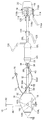
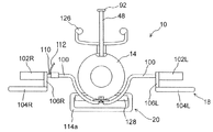
図1は、この実施例に係る水中スクータの平面図である。また、図2は、図1に示す水中スクータの左側面図であり、図3は、図1に示す水中スクータの正面図である。   FIG. 1 is a plan view of an underwater scooter according to this embodiment. 2 is a left side view of the underwater scooter shown in FIG. 1, and FIG. 3 is a front view of the underwater scooter shown in FIG.

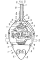
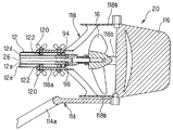
図1から図3において、符号10は水中スクータを示す。先ず、水中スクータ10の構成について概説すると、水中スクータ10は、円筒状に形成されてその長手方向が水中スクータ10の進行方向に対して平行となるように配置されたメインフレーム12と、メインフレーム12において進行方向前方に配置された卵型の水密(気密)容器14と、水密容器14の内部に収容された内燃機関(駆動源。図1から図3で図示せず。以下「エンジン」という)と、メインフレーム12において進行方向後方に配置され、エンジンで駆動されて回転して水中スクータ10を推進させるプロペラ16と、メインフレーム12の内部に挿通されてエンジンの出力をプロペラ16に伝達するドライブシャフト(図1から図3で図示せず)と、水密容器14の付近に配置されて水中スクータ10の航行深度の調整を行う深度調整機構18と、プロペラ16の付近に配置されて水中スクータ10の進行方向の調整を行う操舵機構20と、メインフレーム12において水密容器14とプロペラ16の間に配置された第1のエアタンク22と第2のエアタンク24を備える。   1 to 3, reference numeral 10 denotes an underwater scooter. First, the configuration of the underwater scooter 10 will be outlined. The underwater scooter 10 is formed in a cylindrical shape, and the main frame 12 is disposed so that its longitudinal direction is parallel to the traveling direction of the underwater scooter 10. 12, an egg-shaped watertight (airtight) container 14 disposed in front of the traveling direction, and an internal combustion engine (drive source not shown in FIGS. 1 to 3) housed in the watertight container 14. Hereinafter referred to as “engine”. ) And a propeller 16 that is disposed behind the main frame 12 in the traveling direction and is driven by the engine to rotate to propel the underwater scooter 10, and is inserted into the main frame 12 to transmit the output of the engine to the propeller 16. The drive shaft (not shown in FIGS. 1 to 3) and the depth of adjustment of the underwater scooter 10 disposed near the watertight container 14 are adjusted. A depth adjusting mechanism 18 for performing the operation, a steering mechanism 20 for adjusting the traveling direction of the underwater scooter 10 disposed in the vicinity of the propeller 16, and a first air tank disposed between the watertight container 14 and the propeller 16 in the main frame 12. 22 and a second air tank 24.

次いで、上記した各構成について詳説する。   Next, each of the above-described configurations will be described in detail.

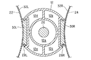
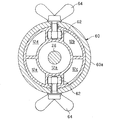
図4は、図1のIV−IV線拡大断面図である。図示の如く、メインフレーム12の内部は区画壁によって分割され、5つの通路が形成される。各通路は、メインフレーム12の先端から後端まで連続する1つの空間として形成される。5つの通路のうち、中心に位置する円筒状の第1の通路12aには、前記したドライブシャフト(符号26で示す)が挿通される。これに対し、第1の通路12aの外周を分割して形成された第2から第5の通路12b,12c,12d,12eは、後述の如く、空気や排出ガスの流路となる。   4 is an enlarged sectional view taken along line IV-IV in FIG. As illustrated, the interior of the main frame 12 is divided by a partition wall to form five passages. Each passage is formed as one space continuous from the front end to the rear end of the main frame 12. Of the five passages, the above-described drive shaft (indicated by reference numeral 26) is inserted into a cylindrical first passage 12a located at the center. On the other hand, the second to fifth passages 12b, 12c, 12d, and 12e formed by dividing the outer periphery of the first passage 12a serve as air and exhaust gas passages as will be described later.

メインフレーム12の両側面には、断面視において略Cの字状(あるいはその左右対称の断面形状)を呈する溝部28L,28Rが形成される。図2に示すように、溝部28L(およびその裏面に位置する溝部28R)は、メインフレーム12の長手方向(進行方向)に所定の長さを有するように形成される。   On both side surfaces of the main frame 12, grooves 28L and 28R having a substantially C-shape (or a symmetric cross-sectional shape thereof) in a sectional view are formed. As shown in FIG. 2, the groove portion 28 </ b> L (and the groove portion 28 </ b> R located on the back surface thereof) is formed to have a predetermined length in the longitudinal direction (traveling direction) of the main frame 12.

図4の説明を続けると、左右の溝部28L,28Rには、それぞれ断面視において略Hの字状を呈するスライダ30L,30Rがスライド自在に嵌められる。即ち、スライダ30L,30Rは、溝部28L,28Rの上端と下端に形成された突起をレールとして、スライド自在に構成される。   If the explanation of FIG. 4 is continued, sliders 30L and 30R each having a substantially H shape in a sectional view are slidably fitted in the left and right grooves 28L and 28R, respectively. That is, the sliders 30L and 30R are configured to be slidable with the protrusions formed on the upper and lower ends of the grooves 28L and 28R as rails.

スライダ30L,30Rには、それぞれベルト32L,32Rが設けられる。前記した第1のエアタンク22と第2のエアタンク24は、ベルト32L,32Rを介してそれぞれスライダ30L,30Rに装着される。これにより、第1のエアタンク22と第2のエアタンク24は、メインフレーム12の長手方向(即ち、水中スクータ10の進行方向)にスライド自在に装着される。   Belts 32L and 32R are provided on the sliders 30L and 30R, respectively. The first air tank 22 and the second air tank 24 described above are mounted on the sliders 30L and 30R via belts 32L and 32R, respectively. Thus, the first air tank 22 and the second air tank 24 are slidably mounted in the longitudinal direction of the main frame 12 (that is, the traveling direction of the underwater scooter 10).

図1から図3の説明に戻ると、第1のエアタンク22は、バルブ36を介してレギュレータ38に接続される。レギュレータ38は、ホース40を介してメインフレーム12の内部(具体的には第2の通路12b)に接続される。一方、第2のエアタンク24は、バルブ42を介してレギュレータ44に接続される。レギュレータ44は、ホース46を介してメインフレーム12の内部(具体的には、第3の通路12c)に接続される。尚、第1および第2のエアタンク22,24の容積は、例えば12リットル程度であり、その内部には空気が高圧(例えば200気圧程度)に圧縮されて封入される。   Returning to the description of FIG. 1 to FIG. 3, the first air tank 22 is connected to a regulator 38 via a valve 36. The regulator 38 is connected to the inside of the main frame 12 (specifically, the second passage 12b) via the hose 40. On the other hand, the second air tank 24 is connected to a regulator 44 via a valve 42. The regulator 44 is connected to the inside of the main frame 12 (specifically, the third passage 12c) via the hose 46. The volumes of the first and second air tanks 22 and 24 are, for example, about 12 liters, and the air is compressed and sealed in the interior at a high pressure (for example, about 200 atmospheres).

第1のエアタンク22に封入された空気は、レギュレータ38で所定の圧力(例えば10気圧程度)まで減圧された後、ホース40を介してメインフレーム12の第2の通路12bに供給される。一方、第2のエアタンク24に封入された空気は、レギュレータ44で前記した所定の圧力(10気圧程度)まで減圧された後、ホース46を介してメインフレーム12の第3の通路12cに供給される。   The air sealed in the first air tank 22 is depressurized to a predetermined pressure (for example, about 10 atm) by the regulator 38 and then supplied to the second passage 12 b of the main frame 12 through the hose 40. On the other hand, the air sealed in the second air tank 24 is reduced to the predetermined pressure (about 10 atmospheres) by the regulator 44 and then supplied to the third passage 12 c of the main frame 12 through the hose 46. The

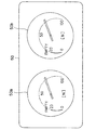
また、水密容器14の上面には、シュノーケル48と計器盤50が設けられる。計器盤50には、図5に良く示す如く、第1のエアタンク22の空気残量を検出して表示する第1の圧力計50a(第1の空気残量表示手段)と、第2のエアタンク24の空気残量を検出して表示する第2の圧力計50b(第2の空気残量表示手段)が配置される。第1の圧力計50aは、具体的には高圧ホース50a1を介して第1のエアタンク22に接続され、第1のエアタンク22の出口圧力に応じてその空気残量をパーセンテージで表示する。また、第2の圧力計50bは、高圧ホース50b1を介して第2のエアタンク24に接続され、第2のエアタンク24の出口圧力に応じてその空気残量をパーセンテージで表示する。   A snorkel 48 and an instrument panel 50 are provided on the upper surface of the watertight container 14. As shown in FIG. 5, the instrument panel 50 has a first pressure gauge 50a (first air remaining amount display means) for detecting and displaying the remaining air amount in the first air tank 22, and a second air tank. A second pressure gauge 50b (second air remaining amount display means) for detecting and displaying 24 remaining air amounts is arranged. Specifically, the first pressure gauge 50a is connected to the first air tank 22 via the high-pressure hose 50a1, and displays the remaining amount of air in percentage according to the outlet pressure of the first air tank 22. The second pressure gauge 50b is connected to the second air tank 24 via the high-pressure hose 50b1, and displays the remaining amount of air as a percentage according to the outlet pressure of the second air tank 24.

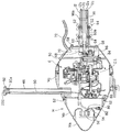
図6は、図1のVI−VI線拡大断面図である。また、図7は、図2のVII−VII線拡大断面図である。   6 is an enlarged sectional view taken along line VI-VI in FIG. FIG. 7 is an enlarged sectional view taken along line VII-VII in FIG.

図6および図7に示すように、水密容器14は、進行方向前方からバンパー14a、燃料タンク14bおよびエンジン収容部14cの3つの部材から構成される。   As shown in FIGS. 6 and 7, the watertight container 14 is composed of three members, a bumper 14a, a fuel tank 14b, and an engine accommodating portion 14c from the front in the traveling direction.

エンジン収容部14cには、エンジンEが収容される。エンジンEは、例えば排気量30cc程度の単気筒火花点火式ガソリンエンジンである。また、エンジン収容部14cの上部には、上方へと突出するシュノーケル48が設けられ、かかるシュノーケル48を介してエンジン収容部14cの内部と外部(大気)とが連通される。   The engine E is accommodated in the engine accommodating portion 14c. The engine E is, for example, a single cylinder spark ignition type gasoline engine having a displacement of about 30 cc. A snorkel 48 that protrudes upward is provided on the upper portion of the engine housing portion 14c, and the inside and the outside (atmosphere) of the engine housing portion 14c communicate with each other via the snorkel 48.

エンジン収容部14cの前方には、ボルト52によって燃料タンク14bが取り付けられ、燃料タンク14bには、エンジンEに供給されるべきガソリン燃料が貯留される。また、燃料タンク14bの前面には給油口54が穿設され、給油口54は、キャップ56によって封止される。   A fuel tank 14b is attached to the front of the engine housing portion 14c by a bolt 52, and gasoline fuel to be supplied to the engine E is stored in the fuel tank 14b. Further, a fuel supply port 54 is formed in the front surface of the fuel tank 14 b, and the fuel supply port 54 is sealed with a cap 56.

燃料タンク14bの前方には、前記キャップ56を被覆するようにバンパー14aが取り付けられる。バンパー14aは、水中スクータ10が外部と衝突したときに変形して衝撃を緩和できるように、他の部材よりも硬度の小さい材料で形成される。また、バンパー14aは、燃料タンク14bへのガソリン燃料の供給を容易に行うことができるように、工具を使用することなく着脱自在とされる。   A bumper 14a is attached to the front of the fuel tank 14b so as to cover the cap 56. The bumper 14a is formed of a material having a hardness lower than that of other members so that the bumper 14a can be deformed and relieve the impact when the underwater scooter 10 collides with the outside. The bumper 14a is detachable without using a tool so that gasoline fuel can be easily supplied to the fuel tank 14b.

また、エンジン収容部14cの後方には、ボルト58によって接続部材60が取り付けられる。接続部材60は、メインフレーム12の直径と略同径の内径を有する円筒部60aを備える。   Further, a connection member 60 is attached to the rear of the engine housing portion 14c by a bolt 58. The connection member 60 includes a cylindrical portion 60 a having an inner diameter that is substantially the same as the diameter of the main frame 12.

図8は、図6のVIII−VIII線拡大断面図である。図8に示すように、メインフレーム12の先端付近には、ナット62が収容される。図6から図8に示すように、接続部材60の円筒部60aにメインフレーム12の先端を挿入し、ちょうボルト64をナット62に螺合させることにより、メインフレーム12の前方に接続部材60を介して水密容器14が取り付けられる。尚、ナット62は、図8に示す如く周囲を区画壁で囲われ、その回転が抑止される。   8 is an enlarged sectional view taken along line VIII-VIII in FIG. As shown in FIG. 8, a nut 62 is accommodated near the tip of the main frame 12. As shown in FIGS. 6 to 8, the end of the main frame 12 is inserted into the cylindrical portion 60 a of the connection member 60, and the butterfly bolt 64 is screwed into the nut 62, thereby connecting the connection member 60 to the front of the main frame 12. The watertight container 14 is attached via The nut 62 is surrounded by a partition wall as shown in FIG. 8, and its rotation is suppressed.

図6および図7の説明に戻ると、メインフレーム12の第2の通路12bは、接続部材60に形成された連通路60b(図7に示す)を介し、水密容器14内に配置されたレギュレータ68に接続される。また、第3の通路12cは、接続部材60の内部に形成された連通路(図示せず)と水密容器14内に設けられた流路70を介し、水密容器14の外部へと連続するホース72に接続される。ホース72の先端には、レギュレータ74が接続され、レギュレータ74には、さらにマウスピース76(いずれも図1および図2に示す)が接続される。   Returning to the description of FIGS. 6 and 7, the second passage 12 b of the main frame 12 is a regulator disposed in the watertight container 14 via a communication passage 60 b (shown in FIG. 7) formed in the connection member 60. 68. Further, the third passage 12c is a hose that continues to the outside of the watertight container 14 via a communication passage (not shown) formed inside the connection member 60 and a flow path 70 provided in the watertight container 14. 72. A regulator 74 is connected to the tip of the hose 72, and a mouthpiece 76 (both shown in FIGS. 1 and 2) is further connected to the regulator 74.

また、メインフレーム12の第4の通路12dは、接続部材60に形成された連通路60cを介してエンジンEの排気管78に接続される。尚、図示は省略するが、第5の通路12eは、接続部材60に形成された連通路を介して水密容器14の内部と連通される。   Further, the fourth passage 12 d of the main frame 12 is connected to the exhaust pipe 78 of the engine E through a communication passage 60 c formed in the connection member 60. Although not shown, the fifth passage 12e communicates with the inside of the watertight container 14 through a communication passage formed in the connection member 60.

エンジンEは、図示しない吸気管を備える。吸気管の入口付近にはエアフィルタが設けられると共に、その下流にはスロットルボディ(いずれも図示せず)が配置される。スロットルボディにはスロットルバルブが収容されると共に、その上流側にはキャブレタ・アシー(いずれも図示せず)が設けられる。キャブレタ・アシーには燃料管80(図6に示す)が接続される。燃料管80は燃料タンク14bの内部に連通されると共に、その先端には燃料ポンプ82が接続される。   The engine E includes an intake pipe (not shown). An air filter is provided in the vicinity of the inlet of the intake pipe, and a throttle body (both not shown) is disposed downstream thereof. A throttle valve is accommodated in the throttle body, and a carburetor assembly (both not shown) is provided upstream of the throttle valve. A fuel pipe 80 (shown in FIG. 6) is connected to the carburetor assembly. The fuel pipe 80 communicates with the inside of the fuel tank 14b, and a fuel pump 82 is connected to the tip thereof.

また、エンジンEのクランクシャフトES(図6に示す)の一端には、遠心クラッチ84が接続される。遠心クラッチ84の出力側は減速機構86に接続され、減速機構86の出力側はドライブシャフト26の前端に接続される。尚、水中スクータ10にはエンジンEの回転数を調節する図示しないスロットル装置が設けられ、遠心クラッチ84は、エンジンEの回転数が上昇させられたときにその動力を伝達する。   A centrifugal clutch 84 is connected to one end of the crankshaft ES (shown in FIG. 6) of the engine E. The output side of the centrifugal clutch 84 is connected to the speed reduction mechanism 86, and the output side of the speed reduction mechanism 86 is connected to the front end of the drive shaft 26. The underwater scooter 10 is provided with a throttle device (not shown) for adjusting the rotational speed of the engine E, and the centrifugal clutch 84 transmits the power when the rotational speed of the engine E is increased.

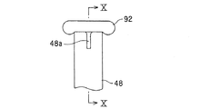
一方、クランクシャフトESの他端には、リコイルスタータ88が取り付けられる。リコイルスタータ88のスタータロープ90は、シュノーケル48の内部に挿通されると共に、その先端にはスタータグリップ92が設けられる。スタータグリップ92は、シュノーケル48の上端に着脱自在に構成される。具体的には、スタータグリップ92は、シュノーケル48の上端にその開口部を水密に封止するように装着されると共に、前記上端から取り外し自在に構成される。即ち、エンジンEを始動させる際はシュノーケル48の上端からスタータグリップ92を取り外し、スタータロープ90を引き出す。エンジンEを始動した後は、シュノーケル48から水が浸入するのを防止すべく、シュノーケル48の上端にスタータグリップ92を取り付けてその開口部を封止する。   On the other hand, a recoil starter 88 is attached to the other end of the crankshaft ES. The starter rope 90 of the recoil starter 88 is inserted into the snorkel 48 and a starter grip 92 is provided at the tip thereof. The starter grip 92 is configured to be detachable from the upper end of the snorkel 48. Specifically, the starter grip 92 is attached to the upper end of the snorkel 48 so as to seal the opening in a watertight manner, and is configured to be removable from the upper end. That is, when starting the engine E, the starter grip 92 is removed from the upper end of the snorkel 48 and the starter rope 90 is pulled out. After starting the engine E, in order to prevent water from entering from the snorkel 48, a starter grip 92 is attached to the upper end of the snorkel 48 and its opening is sealed.

図9は、シュノーケル48の上端付近の拡大図であり、図10は図9のX−X線断面図である。図9および図10に示す如く、シュノーケル48の上端には、取り外したスタータグリップ92(図10に破線で示す)を係止すべき切り欠き部48aが設けられる。   9 is an enlarged view near the upper end of the snorkel 48, and FIG. 10 is a cross-sectional view taken along the line XX of FIG. As shown in FIGS. 9 and 10, the upper end of the snorkel 48 is provided with a notch 48 a to which the removed starter grip 92 (shown by a broken line in FIG. 10) is to be locked.

ここで、第1のエアタンク22から所定の圧力に減圧されてメインフレーム12の第2の通路12bに供給された空気は、連通路60bを介してレギュレータ68に供給されると共に、レギュレータ68で水密容器14の内圧まで減圧された後、水密容器14の内部(具体的にはエンジン収容部14c)に供給される。   Here, the air that has been decompressed to a predetermined pressure from the first air tank 22 and is supplied to the second passage 12b of the main frame 12 is supplied to the regulator 68 through the communication passage 60b, and is also watertight by the regulator 68. After the pressure is reduced to the internal pressure of the container 14, the pressure is supplied to the inside of the watertight container 14 (specifically, the engine housing portion 14 c).

水密容器14に供給された空気は、エアフィルタを介して吸気管に吸入される。キャブレタ・アシーは、吸入された空気にガソリン燃料を噴射して混合気を生成する。生成された混合気は、エンジンEの燃焼室(図示せず)に吸入されて燃焼させられる。混合気の燃焼によって生じた排出ガスは、排気管78および連通路60cを介してメインフレーム12の第4の通路12dに流入する。   The air supplied to the watertight container 14 is sucked into the intake pipe through the air filter. The carburetor assembly injects gasoline fuel into the inhaled air to generate an air-fuel mixture. The generated air-fuel mixture is sucked into a combustion chamber (not shown) of the engine E and burned. The exhaust gas generated by the combustion of the air-fuel mixture flows into the fourth passage 12d of the main frame 12 through the exhaust pipe 78 and the communication passage 60c.

一方、第2のエアタンク24から所定の圧力に減圧されてメインフレーム12の第3の通路12cに供給された空気は、前記した連通路と流路70、さらにはホース72を介してレギュレータ74に供給される。レギュレータ74は、図示しないダイヤフラムなどを備え、マウスピース76を咥えた操縦者(ダイバー)によって吸気動作が行われたとき、周囲の水圧まで減圧した空気を操縦者に供給する。   On the other hand, the air that has been depressurized from the second air tank 24 to a predetermined pressure and supplied to the third passage 12c of the main frame 12 is supplied to the regulator 74 via the communication passage and the passage 70, and further through the hose 72. Supplied. The regulator 74 includes a diaphragm or the like (not shown), and when the intake operation is performed by the operator (diver) holding the mouthpiece 76, the regulator 74 supplies the operator with the air reduced to the surrounding water pressure.

このように、水中スクータ10にあっては、メインフレーム12に第1のエアタンク22を取り付け、第1のエアタンク22に封入された空気をエンジンEの燃焼用の空気として供給するようにした。また、メインフレーム12に第2のエアタンク24を取り付け、第2のエアタンク24に封入された空気を操縦者の呼吸用の空気として供給するようにした。   As described above, in the underwater scooter 10, the first air tank 22 is attached to the main frame 12, and the air sealed in the first air tank 22 is supplied as combustion air for the engine E. In addition, a second air tank 24 is attached to the main frame 12, and the air sealed in the second air tank 24 is supplied as air for breathing of the operator.

図11は、図1のXI−XI線拡大断面図である。   11 is an enlarged sectional view taken along line XI-XI in FIG.

図11に示す如く、第1の通路12aに挿通されたドライブシャフト26の後端には、プロペラ16が取り付けられる。即ち、水中スクータ10は、メインフレーム12の前方に配置されたエンジンEの出力を前記した遠心クラッチ84、減速機構86およびメインフレーム12の内部に挿通されたドライブシャフト26を介してメインフレーム12の後方に配置されたプロペラ16に伝達し、よってプロペラ16を駆動して水上または水中を航行する。   As shown in FIG. 11, the propeller 16 is attached to the rear end of the drive shaft 26 inserted through the first passage 12a. That is, the underwater scooter 10 receives the output of the engine E disposed in front of the main frame 12 through the centrifugal clutch 84, the speed reduction mechanism 86, and the drive shaft 26 inserted into the main frame 12 so that the main frame 12 It is transmitted to the propeller 16 disposed at the rear, and thus the propeller 16 is driven to sail on or under water.

また、メインフレーム12の第4の通路12dの後端には、第1のワンウェイチェックバルブ94が配置される。第1のワンウェイチェックバルブ94は、排出ガスが第4の通路12dに流入してその内圧が所定の圧力を上回ったときに開弁し、第4の通路12dを外部(水中)に連通させる。即ち、エンジンEから排出された排出ガスは、排気管78、連通路60c、メインフレーム12の第4の通路12dおよび第1のワンウェイチェックバルブ94を介して水中スクータ10の後方(外部)へと排出される。   A first one-way check valve 94 is disposed at the rear end of the fourth passage 12d of the main frame 12. The first one-way check valve 94 opens when the exhaust gas flows into the fourth passage 12d and the internal pressure thereof exceeds a predetermined pressure, and communicates the fourth passage 12d to the outside (underwater). That is, the exhaust gas exhausted from the engine E passes to the rear (outside) of the underwater scooter 10 via the exhaust pipe 78, the communication passage 60c, the fourth passage 12d of the main frame 12, and the first one-way check valve 94. Discharged.

さらに、メインフレーム12の第5の通路12eの後端には、第2のワンウェイチェックバルブ96が配置される。第2のワンウェイチェックバルブ96は、第5の通路12eの内圧(別言すれば、第5の通路12eに連通された水密容器14の内圧)が所定の圧力を上回ったときに開弁し、第5の通路12eを外部(水中)に連通させる。即ち、エンジンEの発熱などによって水密容器14の内圧が上昇すると、水密容器14内の空気が、接続部材60に形成された連通路、メインフレーム12の第5の通路12eおよび第2のワンウェイチェックバルブ96を介して水中スクータ10の後方(外部)へと排出され、よって水密容器14の内圧が調整(減圧)される。   Further, a second one-way check valve 96 is disposed at the rear end of the fifth passage 12 e of the main frame 12. The second one-way check valve 96 opens when the internal pressure of the fifth passage 12e (in other words, the internal pressure of the watertight container 14 communicated with the fifth passage 12e) exceeds a predetermined pressure, The fifth passage 12e is communicated with the outside (underwater). That is, when the internal pressure of the watertight container 14 rises due to heat generated by the engine E, etc., the air in the watertight container 14 flows into the communication path formed in the connecting member 60, the fifth path 12e of the main frame 12, and the second one-way check. The water is discharged to the rear (outside) of the underwater scooter 10 through the valve 96, and the internal pressure of the watertight container 14 is adjusted (depressurized).

上記の如く、メインフレーム12に形成された第1の通路12aは、ドライブシャフト26の挿通路となる。また、第2の通路12bは、エンジンEに供給されるべき燃焼用空気の流路となり、第3の通路12cは、操縦者に供給されるべき呼吸用空気の流路となる。さらに、第4の通路12dは、エンジンEから排出された排出ガスの流路となり、第5の通路12eは、水密容器14内の空気を外部に排出してその内圧を調整するための連通路となる。   As described above, the first passage 12 a formed in the main frame 12 serves as an insertion passage for the drive shaft 26. The second passage 12b is a flow path for combustion air to be supplied to the engine E, and the third passage 12c is a flow path for breathing air to be supplied to the operator. Further, the fourth passage 12d is a flow path for exhaust gas discharged from the engine E, and the fifth passage 12e is a communication passage for discharging the air in the watertight container 14 to the outside and adjusting its internal pressure. It becomes.

尚、図示は省略するが、第2の通路12bと第3の通路12cは、メインフレーム12の後端において封止される。第2の通路12bと第3の通路12cをメインフレーム12の後端で封止するのは、メインフレーム12の前端から後端に空気を充満させ、メインフレーム12全体に均等な浮力を与えるためである。第4の通路12dと第5の通路12eにおいて各ワンウェイチェックバルブをそれらの後端に配置したのも、同様な理由からである。   Although not shown, the second passage 12b and the third passage 12c are sealed at the rear end of the main frame 12. The reason why the second passage 12b and the third passage 12c are sealed at the rear end of the main frame 12 is to fill the air from the front end to the rear end of the main frame 12 and to give the main frame 12 the same buoyancy. It is. For the same reason, the one-way check valves are arranged at the rear ends of the fourth passage 12d and the fifth passage 12e.

ここで、図6および図7に示すように、第2の通路12bと第3の通路12cには切り替えバルブ98(空気供給先変更手段)が配置される。切り替えバルブ98は、操縦者によって手動操作自在な切り替えスイッチ98aを備え、かかるスイッチ98aの操作に応じ、切り替えバルブ98よりも上流側の第2の通路12bとそれよりも下流側の第3の通路12cを連通させると共に、切り替えバルブ98よりも上流側の第3の通路12cとそれよりも下流側の第2の通路12bを連通させる。   Here, as shown in FIGS. 6 and 7, a switching valve 98 (air supply destination changing means) is disposed in the second passage 12b and the third passage 12c. The changeover valve 98 includes a changeover switch 98a that can be manually operated by the operator, and the second passage 12b upstream of the changeover valve 98 and the third passage downstream of the changeover valve 98 according to the operation of the switch 98a. 12 c is communicated, and the third passage 12 c on the upstream side of the switching valve 98 and the second passage 12 b on the downstream side thereof are communicated.

即ち、切り替えバルブ98は、切り替えスイッチ98aの操作に応じて第1および第2のエアタンク22,24に封入された空気の供給先を変更する、具体的には、第1のエアタンク22に封入された空気が呼吸用空気として操縦者に供給されると共に、第2のエアタンク24に封入された空気が燃焼用空気としてエンジンEに供給されるように、各エアタンクに封入された空気の供給先を変更する。   That is, the changeover valve 98 changes the supply destination of the air enclosed in the first and second air tanks 22 and 24 according to the operation of the changeover switch 98a. Specifically, the changeover valve 98 is enclosed in the first air tank 22. Air is supplied to the operator as breathing air, and the air supplied to each air tank is supplied to the engine E as combustion air. change.

図1から図3の説明に戻ると、水密容器14には、水中スクータ10を潜行あるいは浮上させて航行深度を調整する深度調整機構18が取り付けられる。深度調整機構18は、バー100と、円筒状の左右のグリップ102L,102Rと、上面視略台形のプレートからなる左右のエレベータ104L,104Rと、グリップ102L,102Rをエレベータ104L,104Rに接続する接続部材106L,106Rとからなる。   Returning to the description of FIG. 1 to FIG. 3, the watertight container 14 is provided with a depth adjustment mechanism 18 that adjusts the navigation depth by causing the underwater scooter 10 to dive or float. The depth adjusting mechanism 18 includes a bar 100, cylindrical left and right grips 102L and 102R, left and right elevators 104L and 104R made of a substantially trapezoidal plate when viewed from above, and connections for connecting the grips 102L and 102R to the elevators 104L and 104R. It consists of members 106L and 106R.

深度調整機構18について具体的に説明すると、バー100は水密容器14に取り付けられ、その長手方向が水中スクータ10の左右方向に対して平行となるように配置される。バー100において進行方向に向かって左側の端部には、左グリップ102Lが取り付けられる。同様に、バー100において進行方向に向かって右側の端部には、右グリップ102Rが取り付けられる。尚、左右のグリップ102L,102Rは、それぞれバー100を中心として回転(具体的には自転)自在に取り付けられる。   The depth adjusting mechanism 18 will be described in detail. The bar 100 is attached to the watertight container 14 and is arranged so that its longitudinal direction is parallel to the left-right direction of the underwater scooter 10. A left grip 102L is attached to the left end of the bar 100 in the traveling direction. Similarly, a right grip 102R is attached to the right end of the bar 100 in the traveling direction. The left and right grips 102L and 102R are attached so as to be rotatable (specifically, rotate) around the bar 100, respectively.

左右のグリップ102L,102Rには、それぞれ接続部材106L,106Rを介してエレベータ104L,104Rが接続される。これにより、エレベータ104L,104Rは、水中スクータ10の左右軸回りに揺動自在とされる。即ち、グリップ102L,102Rを回転させることにより、エレベータ104L,104Rの左右軸回りの傾きの大きさと方向を変更することができ、よってエレベータ104L,104Rに作用する揚力(水中スクータ10を潜行あるいは浮上させる力)を調整することができる。   Elevators 104L and 104R are connected to the left and right grips 102L and 102R via connecting members 106L and 106R, respectively. Thereby, the elevators 104 </ b> L and 104 </ b> R can swing around the left and right axes of the underwater scooter 10. That is, by rotating the grips 102L and 102R, the magnitude and direction of the inclination of the elevators 104L and 104R around the left and right axes can be changed, and thus the lift force acting on the elevators 104L and 104R (the underwater scooter 10 is submerged or floated). Force) can be adjusted.

また、バー100の適宜位置には、エマージェンシスイッチ110が設けられる。エマージェンシスイッチ110には、そのオン、オフのトリガーとなるエマージェンシコード112(図1および図3に示す)の一端が取り付けられる。エマージェンシコード112の他端は、後述する如く、操縦者の腕に取り付けられる。   Further, an emergency switch 110 is provided at an appropriate position of the bar 100. The emergency switch 110 is attached with one end of an emergency cord 112 (shown in FIG. 1 and FIG. 3) that is an on / off trigger. The other end of the emergency cord 112 is attached to the operator's arm as will be described later.

一方、メインフレーム12の後端には、操舵機構20が取り付けられる。操舵機構20は、フットスタンド114と、フットスタンド114に接続されたラダー116と、それらをメインフレーム12に接続する接続部材118とからなる。   On the other hand, a steering mechanism 20 is attached to the rear end of the main frame 12. The steering mechanism 20 includes a foot stand 114, a ladder 116 connected to the foot stand 114, and a connection member 118 that connects them to the main frame 12.

操舵機構20について具体的に説明すると、接続部材118は、メインフレーム12の直径と略同径の内径を有する円筒部118aを備える。図11に良く示すように、かかる円筒部118aにメインフレーム12の後端を挿入し、ちょうボルト120をメインフレーム12の内部に収容されたナット122に螺合させることにより、メインフレーム12に接続部材118、別言すれば、操舵機構20が取り付けられる。尚、図示は省略するが、ナット122も前述のナット62と同様に周囲を区画壁で囲われ、その回転が抑止される。   The steering mechanism 20 will be specifically described. The connection member 118 includes a cylindrical portion 118 a having an inner diameter that is substantially the same as the diameter of the main frame 12. As shown well in FIG. 11, the rear end of the main frame 12 is inserted into the cylindrical portion 118 a, and the butterfly bolt 120 is screwed into the nut 122 accommodated in the main frame 12 to be connected to the main frame 12. The member 118, in other words, the steering mechanism 20 is attached. Although illustration is omitted, the nut 122 is also surrounded by a partition wall in the same manner as the nut 62 described above, and its rotation is suppressed.

接続部材118は、前記円筒部118aに連続する上下左右の計4枚の翼部118bを備える。翼部118bは、プロペラ16との接触を上下方向あるいは左右方向に回避するように形成されると共に、それらの後端は、プロペラ16よりも後方に位置させられる。上記したフットスタンド114とそれに接続されたラダー116は、翼部118bの中、上下に配置された2枚の翼部の後端に上下軸回りに揺動自在に支持される。即ち、フットスタンド114を操作する(上下軸回りに回転させる)ことにより、ラダー116を上下軸回りに揺動させることができ、よって水中スクータ10の進行方向を調整することができる。   The connecting member 118 includes a total of four wings 118b on the top, bottom, left, and right that are continuous with the cylindrical part 118a. The wings 118b are formed so as to avoid contact with the propeller 16 in the up-down direction or the left-right direction, and their rear ends are positioned rearward of the propeller 16. The above-mentioned foot stand 114 and the ladder 116 connected thereto are supported so as to be swingable around the vertical axis at the rear ends of the two wing portions arranged vertically in the wing portion 118b. That is, by operating the foot stand 114 (rotating about the vertical axis), the ladder 116 can be swung about the vertical axis, and thus the traveling direction of the underwater scooter 10 can be adjusted.

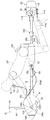
図12は、水中スクータ10と、それに騎乗した操縦者を示す左側面図である。   FIG. 12 is a left side view showing the underwater scooter 10 and the rider riding it.

図12に示すように、操縦者OPは、第1のエアタンク22と第2のエアタンク24の上に騎乗する。具体的には、操縦者OPは、メインフレーム12を跨ぐようにして第1のエアタンク22と第2のエアタンク24に着座する。そして、前傾姿勢をとって前方に位置する左右のグリップ102L,102Rを把持すると共に、後方に位置するフットスタンド114の載置部114aに足を載置する、具体的には、足の甲を係止させる。尚、載置部114aは、図1に示すように、平面視において環状を呈する。   As shown in FIG. 12, the pilot OP rides on the first air tank 22 and the second air tank 24. Specifically, the pilot OP sits on the first air tank 22 and the second air tank 24 so as to straddle the main frame 12. Then, the left and right grips 102L and 102R are held in a forward tilted posture, and the feet are placed on the placement portion 114a of the foot stand 114 located at the rear. Lock. In addition, the mounting part 114a exhibits a ring shape in a plan view as shown in FIG.

このとき、操縦者OPの腰部は、前記したスライダ30L,30Rに取り付けられたウェストホルダ126に支持される。また、操縦者OPの膝裏は、メインフレーム12に取り付けられたフットホルダ128に支持される。尚、フットホルダ128は、前述した接続部材60などと同様に、メインフレーム12の内部に収容されてその回転が抑止されたナット(図示せず)とちょうボルト130を螺合させることによって取り付けられる。   At this time, the waist of the pilot OP is supported by the waist holder 126 attached to the sliders 30L and 30R. Further, the back of the knee of the operator OP is supported by a foot holder 128 attached to the main frame 12. The foot holder 128 is attached by screwing a nut bolt (not shown) housed inside the main frame 12 and restrained from rotating with the wing bolt 130, like the connection member 60 described above. .

また、操縦者OPの腕には、前述したエマージェンシコード112(図12で図示省略)の他端が装着される。これにより、操縦者OPが水中スクータ10から離脱したときにエマージェンシコード112の一端がエマージェンシスイッチ110から引き抜かれ、緊急停止信号が送出されてエンジンEが停止させられる。   Further, the other end of the emergency cord 112 (not shown in FIG. 12) is attached to the arm of the operator OP. As a result, when the operator OP leaves the underwater scooter 10, one end of the emergency cord 112 is pulled out from the emergency switch 110, an emergency stop signal is sent, and the engine E is stopped.

次いで、操縦者OPによる水中スクータ10の操縦、具体的には、航行深度と進行方向の調整について説明する。   Next, the operation of the underwater scooter 10 by the operator OP, specifically, the adjustment of the navigation depth and the traveling direction will be described.

先ず、水中スクータ10を潜行させるときは、図13に示す如く、左右のエレベータ104L,104Rの前端を後端よりも下方に位置させるように左右のグリップ102L,102Rを回転させる。この状態で水中スクータ10を前進させることにより、左右のエレベータ104L,104Rには下向きの力が作用し、よって水中スクータ10が潜行させられる。また、このとき、操縦者OPは騎乗部たる第1および第2のエアタンク22,24を後方へとスライドさせる。即ち、第1および第2のエアタンク22,24の浮力が作用する位置を後方へと移動させる。これにより、水中スクータ10の後方の浮力が大きくなり、水中スクータ10の前方が沈み込む(後方が浮き上がる)ことから、潜行に適した(潜行し易い)姿勢となる。   First, when the underwater scooter 10 is submerged, the left and right grips 102L and 102R are rotated so that the front ends of the left and right elevators 104L and 104R are positioned below the rear end, as shown in FIG. By advancing the underwater scooter 10 in this state, a downward force is applied to the left and right elevators 104L and 104R, so that the underwater scooter 10 is submerged. At this time, the pilot OP slides the first and second air tanks 22 and 24, which are riding parts, backward. That is, the position where the buoyancy of the first and second air tanks 22 and 24 acts is moved backward. As a result, the buoyancy behind the underwater scooter 10 increases, and the front of the underwater scooter 10 sinks (the rear rises), so that the posture is suitable for diving (easy to dive).

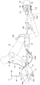
これに対し、水中スクータ10を浮上させるときは、図14に示す如く、左右のエレベータ104L,104Rの前端を後端よりも上方に位置させるように左右のグリップ102L,102Rを回転させる。この状態で水中スクータ10を前進させることにより、左右のエレベータ104L,104Rには上向きの力が作用し、よって水中スクータ10が浮上させられる。また、このとき、操縦者OPは騎乗部たる第1および第2のエアタンク22,24を前方へとスライドさせる。即ち、第1および第2のエアタンク22,24の浮力が作用する位置を前方へと移動させる。これにより、水中スクータ10の前方の浮力が大きくなり、水中スクータ10の前方が浮き上がる(後方が沈み込む)ことから、浮上に適した(浮上し易い)姿勢となる。   On the other hand, when the underwater scooter 10 is levitated, the left and right grips 102L and 102R are rotated so that the front ends of the left and right elevators 104L and 104R are positioned above the rear end, as shown in FIG. By advancing the underwater scooter 10 in this state, an upward force acts on the left and right elevators 104L, 104R, and thus the underwater scooter 10 is lifted. At this time, the pilot OP slides the first and second air tanks 22 and 24, which are riding parts, forward. That is, the position where the buoyancy of the first and second air tanks 22 and 24 acts is moved forward. As a result, the buoyancy in front of the underwater scooter 10 is increased and the front of the underwater scooter 10 is lifted (back sinks), so that the posture is suitable for floating (easy to float).

一方、水中スクータ10の進行方向を調整するときは、フットスタンド114に載置した足でフットスタンド114を左右に操作し、よってラダー116を上下軸回りに揺動させる。これにより、水中スクータ10が左右に操舵される。   On the other hand, when the traveling direction of the underwater scooter 10 is adjusted, the foot stand 114 is operated left and right with the foot placed on the foot stand 114, and thus the ladder 116 is swung around the vertical axis. Thereby, the underwater scooter 10 is steered left and right.

尚、水中スクータ10が水上あるいは水面付近を航行するとき(即ち、航行深度が浅く、シュノーケル48の上端が水面より上方に位置するとき)は、シュノーケル48の上端からスタータグリップ92を取り外して前記切り欠き部48aに係止させる(即ち、開口部を封止しないようにする)ことで、外気をエンジンEの燃焼用空気として取り入れることができる。このとき、第1のエアタンク22に接続されたバルブ36を閉弁し、第1のエアタンク22からの空気の供給は停止させる。   When the underwater scooter 10 navigates on or near the surface of the water (that is, when the navigation depth is shallow and the upper end of the snorkel 48 is located above the water surface), the starter grip 92 is removed from the upper end of the snorkel 48 and the cutting is performed. The outside air can be taken in as combustion air for the engine E by engaging the notch 48a (that is, not sealing the opening). At this time, the valve 36 connected to the first air tank 22 is closed, and the supply of air from the first air tank 22 is stopped.

このように、この実施例に係る水中スクータ10にあっては、円筒状に形成されたメインフレーム12の前方にエンジンEを収容する水密容器14を配置する一方、後方にプロペラ16を配置し、メインフレーム12の内部に挿通されたドライブシャフト26でエンジンEの出力をプロペラ16に伝達すると共に、メインフレーム12においてエンジンEとプロペラ16の間に配置された第1および第2のエアタンク22,24に操縦者OPが騎乗するようにしたので、操縦者を牽引するタイプの従来例に比して操縦者の負担を軽減させることができる。   Thus, in the underwater scooter 10 according to this embodiment, the watertight container 14 that houses the engine E is disposed in front of the cylindrical main frame 12, while the propeller 16 is disposed in the rear. The drive shaft 26 inserted into the main frame 12 transmits the output of the engine E to the propeller 16, and the first and second air tanks 22, 24 disposed between the engine E and the propeller 16 in the main frame 12. Since the pilot OP rides on the vehicle, the burden on the pilot can be reduced as compared with the conventional example in which the pilot is pulled.

また、プロペラ16が操縦者OPよりも後方に配置されると共に、エンジンEの排出ガスがメインフレーム12の第4の通路12dを通過して操縦者OPの後方に排出されることから、プロペラ16から噴出された水流やエンジンEの排出ガスによって操縦者OPの視界が低下するおそれがない。さらに、プロペラ16から噴出された水流やエンジンEの排出ガスによって操縦者OPの装着物(ゴーグルなど)が脱落するおそれもない。   In addition, the propeller 16 is disposed behind the pilot OP, and the exhaust gas of the engine E passes through the fourth passage 12d of the main frame 12 and is discharged behind the pilot OP. There is no possibility that the visibility of the pilot OP is lowered by the water flow ejected from the engine or the exhaust gas of the engine E. In addition, there is no possibility that the attached items (goggles, etc.) of the pilot OP will drop off due to the water flow ejected from the propeller 16 or the exhaust gas of the engine E.

また、エンジンEが収容される水密容器14の内部を大気に連通させるシュノーケル48と、水密容器14の内部に供給されるべき空気が封入された第1のエアタンク22とを備えるようにしたことから、水中スクータ10が水上を航行するときはシュノーケル48と第1のエアタンク22の少なくともいずれかからエンジンEに燃焼用空気を供給することができると共に、水中スクータ10が水中を航行しているときは第1のエアタンク22から燃焼用空気を供給することができ、よってエンジンEでプロペラ16を駆動して水上と水中の両方を航行することができる。   Further, since the water-tight container 14 in which the engine E is accommodated is provided with a snorkel 48 that communicates with the atmosphere, and the first air tank 22 in which the air to be supplied into the water-tight container 14 is enclosed. When the underwater scooter 10 sails on the water, combustion air can be supplied from at least one of the snorkel 48 and the first air tank 22 to the engine E, and when the underwater scooter 10 sails underwater. Combustion air can be supplied from the first air tank 22, and therefore the propeller 16 can be driven by the engine E to navigate both on and under water.

また、エンジンEを始動するリコイルスタータ88を備えると共に、前記リコイルスタータのスタータグリップ92によってシュノーケル48の開口部を封止するようにしたので、水密容器14に収容されたエンジンEの始動を容易に行うことができると共に、水中スクータ10が潜行しているときにシュノーケル48から水密容器14の内部に水が浸入するのを防止することができる。   In addition, since the recoil starter 88 for starting the engine E is provided and the opening of the snorkel 48 is sealed by the starter grip 92 of the recoil starter, the engine E housed in the watertight container 14 can be easily started. In addition, the water can be prevented from entering the watertight container 14 from the snorkel 48 when the underwater scooter 10 is submerged.

また、操縦者OPに供給されるべき空気が封入された第2のエアタンク24を備えるようにしたので、エンジンEへの燃焼用空気の供給と操縦者OPへの呼吸用空気の供給を同時に行うことができ、よって操縦者の快適性を向上させることができる。   In addition, since the second air tank 24 filled with air to be supplied to the pilot OP is provided, the combustion air is supplied to the engine E and the breathing air is supplied to the pilot OP at the same time. Therefore, the driver's comfort can be improved.

また、第1のエアタンク22の空気残量を検出して表示する第1の圧力計50aと第2のエアタンク24の空気残量を検出して表示する第2の圧力計50bを備えるようにしたので、水中スクータ10の潜行可能時間(距離)および操縦者OPの潜行可能時間(呼吸可能時間)を報知することができる。   Further, a first pressure gauge 50a for detecting and displaying the remaining amount of air in the first air tank 22 and a second pressure gauge 50b for detecting and displaying the remaining amount of air in the second air tank 24 are provided. Therefore, the submersible time (distance) of the underwater scooter 10 and the submersible time (breathable time) of the pilot OP can be notified.

また、第1および第2のエアタンク22,24が、メインフレーム12に水中スクータ10の進行方向においてスライド自在に装着されるようにしたので、各エアタンクの浮力が作用する位置を変更することができる。このため、水中スクータ10の姿勢を潜行または浮上に適した姿勢に変更することができ、よって水中スクータ10の深度調整を容易に行うことができる。   In addition, since the first and second air tanks 22 and 24 are slidably mounted on the main frame 12 in the traveling direction of the underwater scooter 10, the position where the buoyancy of each air tank acts can be changed. . For this reason, the posture of the underwater scooter 10 can be changed to a posture suitable for diving or ascending, and therefore the depth adjustment of the underwater scooter 10 can be easily performed.

また、遠心クラッチ84を介してエンジンEの出力をプロペラ16に伝達するようにしたので、エンジンEの運転を停止することなく水中スクータ10の航行を停止することができる。   Moreover, since the output of the engine E is transmitted to the propeller 16 via the centrifugal clutch 84, the navigation of the underwater scooter 10 can be stopped without stopping the operation of the engine E.

さらに、第1のエアタンク22に封入された空気と第2のエアタンク24に封入された空気の供給先を変更する切り替えバルブ98を備えるようにしたので、燃焼用空気と呼吸用空気の消費量に差が生じても、各エアタンクに封入された空気を効率良く使用することができる。   Further, since the switching valve 98 for changing the supply destination of the air sealed in the first air tank 22 and the air sealed in the second air tank 24 is provided, the consumption amount of the combustion air and the breathing air is increased. Even if a difference occurs, the air sealed in each air tank can be used efficiently.

尚、1個の切り替えバルブによって第1のエアタンク22に封入された空気と第2のエアタンク24に封入された空気の両方の供給先を変更するようにしたが、異なる切り替えバルブによって各エアタンクに封入された空気の供給先を変更するようにしても良い。また、いずれか一方の空気の供給先のみを変更するようにしても良い。   Although the supply destination of both the air sealed in the first air tank 22 and the air sealed in the second air tank 24 is changed by one switching valve, it is sealed in each air tank by a different switching valve. The supplied air supply destination may be changed. Further, only one of the air supply destinations may be changed.

例えば、第1のエアタンク22に封入された空気を操縦者に供給すべく供給先を変更する切り替えバルブを設ければ、第2のエアタンク24を備えない場合であっても、エンジンEの停止時や水中スクータ10の航行深度が浅くシュノーケル48から燃焼用空気が導入できるときは操縦者に呼吸用の空気を供給することができ、よって操縦者の快適性を向上させることができる。また、第2のエアタンク24に封入された空気を水密容器14(エンジンE)に供給すべく供給先を変更する切り替えバルブを設けておくことで、水中スクータ10の潜行可能時間(距離)を延長するという効果を得ることができる。この意図から、特許請求の範囲では、第1のエアタンクに封入された空気を操縦者に供給すべく供給先を変更する手段を「第1の空気供給先変更手段」と記載し、第2のエアタンクに封入された空気を水密容器の内部に供給すべく供給先を変更する手段を「第2の空気供給先変更手段」と記載した。   For example, if a switching valve for changing the supply destination is provided to supply the air sealed in the first air tank 22 to the operator, the engine E can be stopped even when the second air tank 24 is not provided. When the underwater scooter 10 has a shallow navigation depth and combustion air can be introduced from the snorkel 48, the air for breathing can be supplied to the pilot, and thus the comfort of the pilot can be improved. Further, by providing a switching valve for changing the supply destination so as to supply the air sealed in the second air tank 24 to the watertight container 14 (engine E), the submergible time (distance) of the underwater scooter 10 is extended. The effect of doing can be obtained. For this purpose, in the claims, the means for changing the supply destination to supply the air sealed in the first air tank to the operator is referred to as “first air supply destination changing means”, and the second The means for changing the supply destination to supply the air sealed in the air tank to the inside of the watertight container is described as “second air supply destination changing means”.

次いで、この発明の第2実施例に係る水中スクータについて説明する。図15は、第2実施例に係る水中スクータを示す図6と同様な断面図である。   Next, an underwater scooter according to a second embodiment of the present invention will be described. FIG. 15 is a cross-sectional view similar to FIG. 6 showing the underwater scooter according to the second embodiment.

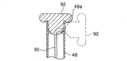
以下、図15を参照して第1実施例との相違点に焦点をおいて説明すると、第2実施例にあっては、リコイルスタータ88のスタータグリップ92に第3のワンウェイチェックバルブ200を配置するように構成した。具体的には、スタータグリップ92に貫通孔92aを穿設し、かかる貫通孔92aに第3のワンウェイチェックバルブ200を配置するようにした。   Hereinafter, the difference from the first embodiment will be described with reference to FIG. 15. In the second embodiment, the third one-way check valve 200 is arranged on the starter grip 92 of the recoil starter 88. Configured to do. Specifically, a through hole 92a is formed in the starter grip 92, and the third one-way check valve 200 is disposed in the through hole 92a.

第3のワンウェイチェックバルブ200は、第1実施例で述べた第2のワンウェイチェックバルブ96と同様に、シュノーケル48の内圧(別言すれば、シュノーケル48に連通された水密容器14の内圧)が所定の圧力を上回ったときに開弁し、シュノーケル48を外部(大気あるいは水中)に連通させる。即ち、エンジンEの発熱などによって水密容器14の内圧が上昇すると、水密容器14内の空気がシュノーケル48および第3のワンウェイチェックバルブ200を介して水中スクータ10の上方(外部)へと排出され、よって水密容器14の内圧が調整(減圧)される。   As with the second one-way check valve 96 described in the first embodiment, the third one-way check valve 200 has an internal pressure of the snorkel 48 (in other words, an internal pressure of the watertight container 14 communicated with the snorkel 48). When the pressure exceeds a predetermined pressure, the valve is opened to allow the snorkel 48 to communicate with the outside (atmosphere or water). That is, when the internal pressure of the watertight container 14 increases due to heat generated by the engine E, the air in the watertight container 14 is discharged to the upper side (outside) of the underwater scooter 10 via the snorkel 48 and the third one-way check valve 200, Therefore, the internal pressure of the watertight container 14 is adjusted (depressurized).

このように、第2実施例に係る水中スクータ10にあっては、シュノーケル48の開口部を封止するスタータグリップ92に、水密容器14の内圧が所定の圧力を上回ったときに開弁して水密容器14を外部に連通させる第3のワンウェイチェックバルブ200を配置するようにしたので、水密容器14の内圧調整(減圧)が可能となる。   Thus, in the underwater scooter 10 according to the second embodiment, the starter grip 92 that seals the opening of the snorkel 48 is opened when the internal pressure of the watertight container 14 exceeds a predetermined pressure. Since the third one-way check valve 200 that allows the watertight container 14 to communicate with the outside is disposed, the internal pressure of the watertight container 14 can be adjusted (depressurized).

尚、残余の構成は第1実施例と同様であるので、説明は省略する。但し、スタータグリップ92に第3のワンウェイチェックバルブ200を配置した場合、第1実施例で述べたメインフレーム12の第5の通路12eと第2のワンウェイチェックバルブ96は省略しても良い。   Since the remaining configuration is the same as that of the first embodiment, description thereof is omitted. However, when the third one-way check valve 200 is disposed in the starter grip 92, the fifth passage 12e of the main frame 12 and the second one-way check valve 96 described in the first embodiment may be omitted.

以上の如く、この発明の第1および第2実施例にあっては、操縦者(OP)に操縦されて水上または水中を航行する水中スクータ(10)において、前記操縦者(OP)が騎乗すべきメインフレーム(12)と、前記メインフレーム(12)に配置された水密容器(14)と、前記水密容器(14)に収容された内燃機関(エンジンE)と、前記内燃機関(E)によって駆動されて回転して前記水中スクータ(10)を推進させるプロペラ(16)と、前記水密容器(14)の内部を大気に連通させるシュノーケル(48)と、前記水密容器(14)の内部に供給されるべき空気が封入された第1のエアタンク(22)とを備えると共に、前記シュノーケル(48)および前記第1のエアタンク(22)の少なくともいずれかから前記内燃機関(E)に燃焼用空気を供給するように構成した。   As described above, in the first and second embodiments of the present invention, the pilot (OP) rides on the underwater scooter (10) that is operated by the pilot (OP) and sails on or under water. Power frame (12), a watertight container (14) disposed on the mainframe (12), an internal combustion engine (engine E) housed in the watertight container (14), and the internal combustion engine (E) A propeller (16) that is driven and rotated to propel the underwater scooter (10), a snorkel (48) that communicates the interior of the watertight container (14) to the atmosphere, and the interior of the watertight container (14) A first air tank (22) in which air to be encapsulated is enclosed, and the internal combustion machine from at least one of the snorkel (48) and the first air tank (22) And configured to supply combustion air to (E).

また、前記第1のエアタンク(22)に封入された空気を前記操縦者(OP)に供給すべく供給先を変更する第1の空気供給先変更手段(切り替えバルブ98)を備えるように構成した。   In addition, it is configured to include first air supply destination changing means (switching valve 98) for changing the supply destination so as to supply the air enclosed in the first air tank (22) to the operator (OP). .

また、前記第1のエアタンク(22)が、前記メインフレーム(12)に前記水中スクータ(10)の進行方向においてスライド自在に装着されるように構成した。   The first air tank (22) is slidably mounted on the main frame (12) in the traveling direction of the underwater scooter (10).

また、前記第1のエアタンク(22)の空気残量を検出して表示する第1の空気残量表示手段(第1の圧力計50a)を備えるように構成した。   The first air tank (22) is configured to include first air remaining amount display means (first pressure gauge 50a) for detecting and displaying the remaining amount of air in the first air tank (22).

また、前記内燃機関(E)を始動するリコイルスタータ(88)を備えると共に、前記リコイルスタータのグリップ(スタータグリップ92)によって前記シュノーケル(48)の開口部を封止するように構成した。   Further, a recoil starter (88) for starting the internal combustion engine (E) is provided, and an opening of the snorkel (48) is sealed by a grip (starter grip 92) of the recoil starter.

また、第2実施例に係る水中スクータにあっては、前記リコイルスタータのグリップ(92)に、前記水密容器(14)の内圧が所定の圧力を上回ったときに開弁して前記水密容器(14)を外部に連通させるワンウェイチェックバルブ(第3のワンウェイチェックバルブ200)を配置するように構成した。   In the underwater scooter according to the second embodiment, the grip (92) of the recoil starter is opened when the internal pressure of the watertight container (14) exceeds a predetermined pressure, and the watertight container ( 14) is configured to arrange a one-way check valve (third one-way check valve 200) that communicates with the outside.

また、第1および第2の実施例に係る水中スクータにあっては、前記操縦者(OP)に供給されるべき空気が封入された第2のエアタンク(24)を備えるように構成した。   The underwater scooters according to the first and second embodiments are configured to include a second air tank (24) in which air to be supplied to the operator (OP) is enclosed.

また、前記第2のエアタンク(24)に封入された空気を前記水密容器(14)の内部に供給すべく供給先を変更する第2の空気供給先変更手段(切り替えバルブ98)を備えるように構成した。   Further, a second air supply destination changing means (switching valve 98) is provided for changing the supply destination so as to supply the air sealed in the second air tank (24) into the watertight container (14). Configured.

また、前記第2のエアタンク(24)が、前記メインフレーム(12)に前記水中スクータ(10)の進行方向においてスライド自在に装着されるように構成した。   The second air tank (24) is slidably mounted on the main frame (12) in the traveling direction of the underwater scooter (10).

また、前記第2のエアタンク(24)の空気残量を検出して表示する第2の空気残量表示手段(第2の圧力計50b)を備えるように構成した。   The second air tank (24) is configured to include second air remaining amount display means (second pressure gauge 50b) for detecting and displaying the remaining air amount in the second air tank (24).

尚、上記において、シュノーケル48とマウスピース76を接続し、水中スクータ10が水上を航行するときは操縦者の呼吸用空気を外部から導入するようにしても良い。このとき、第2のエアタンク24に接続されたバルブ42を閉弁し、第2のエアタンク24からの空気の供給を停止することで、同様に封入された空気の消費量を低減することができる。   In the above, the snorkel 48 and the mouthpiece 76 may be connected, and when the underwater scooter 10 sails on the water, the air for breathing the pilot may be introduced from the outside. At this time, by closing the valve 42 connected to the second air tank 24 and stopping the supply of air from the second air tank 24, the consumption of the enclosed air can be reduced similarly. .

この発明の第1実施例に係る水中スクータの平面図である。It is a top view of the underwater scooter which concerns on 1st Example of this invention. 図1に示す水中スクータの左側面図である。It is a left view of the underwater scooter shown in FIG. 図1に示す水中スクータの正面図である。It is a front view of the underwater scooter shown in FIG. 図1のIV−IV線拡大断面図である。It is the IV-IV line expanded sectional view of FIG. 図1に示す計器盤の拡大図である。It is an enlarged view of the instrument panel shown in FIG. 図1のVI−VI線拡大断面図である。It is the VI-VI line expanded sectional view of FIG. 図2のVII−VII線拡大断面図である。It is the VII-VII line expanded sectional view of FIG. 図6のVIII−VIII線拡大断面図である。It is the VIII-VIII line expanded sectional view of FIG. 図6などに示すシュノーケルの上端付近の拡大図である。It is an enlarged view near the upper end of the snorkel shown in FIG. 図9のX−X線断面図である。FIG. 10 is a sectional view taken along line XX in FIG. 9. 図1のXI−XI線拡大断面図である。It is the XI-XI line expanded sectional view of FIG. 図1に示す水中スクータと、それに騎乗した操縦者を示す左側面図である。FIG. 2 is a left side view showing the underwater scooter shown in FIG. 1 and a driver riding on it. 同様に、図1に示す水中スクータと、それに騎乗した操縦者を示す左側面図である。Similarly, it is the left view which shows the underwater scooter shown in FIG. 1, and the driver who mounted on it. 同様に、図1に示す水中スクータと、それに騎乗した操縦者を示す左側面図である。Similarly, it is the left view which shows the underwater scooter shown in FIG. 1, and the driver who mounted on it. この発明の第2実施例に係る水中スクータを示す、図6と同様な断面図である。It is sectional drawing similar to FIG. 6 which shows the underwater scooter which concerns on 2nd Example of this invention.

符号の説明Explanation of symbols

10 水中スクータ
12 メインフレーム
14 水密容器
16 プロペラ
22 第1のエアタンク
24 第2のエアタンク
50a 第1の圧力計(第1の空気残量表示手段)
50b 第2の圧力計(第2の空気残量表示手段)
88 リコイルスタータ
92 スタータグリップ
98 切り替えバルブ(第1および第2の空気供給先変更手段)
200 第3のワンウェイチェックバルブ
E エンジン(内燃機関)
DESCRIPTION OF SYMBOLS 10 Underwater scooter 12 Main frame 14 Watertight container 16 Propeller 22 1st air tank 24 2nd air tank 50a 1st pressure gauge (1st remaining air display means)
50b Second pressure gauge (second air remaining amount display means)
88 Recoil starter 92 Starter grip 98 Switching valve (first and second air supply destination changing means)
200 Third one-way check valve E Engine (internal combustion engine)

Claims (10)

操縦者に操縦されて水上または水中を航行する水中スクータにおいて、前記操縦者が騎乗すべきメインフレームと、前記メインフレームに配置された水密容器と、前記水密容器に収容された内燃機関と、前記内燃機関によって駆動されて回転して前記水中スクータを推進させるプロペラと、前記水密容器の内部を大気に連通させるシュノーケルと、前記水密容器の内部に供給されるべき空気が封入された第1のエアタンクとを備えると共に、前記シュノーケルおよび前記第1のエアタンクの少なくともいずれかから前記内燃機関に燃焼用空気を供給することを特徴とする水中スクータ。   In an underwater scooter that is piloted by a pilot and sails on the water or underwater, a main frame that the pilot should ride, a watertight container disposed on the main frame, an internal combustion engine housed in the watertight container, A propeller that is driven by an internal combustion engine to rotate to propel the underwater scooter, a snorkel that allows the inside of the watertight container to communicate with the atmosphere, and a first air tank that contains air to be supplied to the inside of the watertight container And a combustion air is supplied to the internal combustion engine from at least one of the snorkel and the first air tank. 前記第1のエアタンクに封入された空気を前記操縦者に供給すべく供給先を変更する第1の空気供給先変更手段を備えることを特徴とする請求項1記載の水中スクータ。   2. The underwater scooter according to claim 1, further comprising first air supply destination changing means for changing a supply destination so as to supply air enclosed in the first air tank to the pilot. 前記第1のエアタンクが、前記メインフレームに前記水中スクータの進行方向においてスライド自在に装着されることを特徴とする請求項1または2記載の水中スクータ。   3. The underwater scooter according to claim 1, wherein the first air tank is slidably attached to the main frame in a traveling direction of the underwater scooter. 前記第1のエアタンクの空気残量を検出して表示する第1の空気残量表示手段を備えることを特徴とする請求項1から3のいずれかに記載の水中スクータ。   The underwater scooter according to any one of claims 1 to 3, further comprising first remaining air amount display means for detecting and displaying the remaining amount of air in the first air tank. 前記内燃機関を始動するリコイルスタータを備えると共に、前記リコイルスタータのグリップによって前記シュノーケルの開口部を封止することを特徴とする請求項1から4のいずれかに記載の水中スクータ。   The underwater scooter according to any one of claims 1 to 4, further comprising a recoil starter for starting the internal combustion engine and sealing an opening of the snorkel with a grip of the recoil starter. 前記リコイルスタータのグリップに、前記水密容器の内圧が所定の圧力を上回ったときに開弁して前記水密容器を外部に連通させるワンウェイチェックバルブを配置したことを特徴とする請求項1から5のいずれかに記載の水中スクータ。   6. The one-way check valve that opens when the internal pressure of the watertight container exceeds a predetermined pressure is disposed on the grip of the recoil starter to communicate the watertight container to the outside. The underwater scooter according to any one of the above. 前記操縦者に供給されるべき空気が封入された第2のエアタンクを備えることを特徴とする請求項1から6のいずれかに記載の水中スクータ。   The underwater scooter according to any one of claims 1 to 6, further comprising a second air tank in which air to be supplied to the operator is enclosed. 前記第2のエアタンクに封入された空気を前記水密容器の内部に供給すべく供給先を変更する第2の空気供給先変更手段を備えることを特徴とする請求項7記載の水中スクータ。   8. The underwater scooter according to claim 7, further comprising second air supply destination changing means for changing a supply destination so as to supply air enclosed in the second air tank to the inside of the watertight container. 前記第2のエアタンクが、前記メインフレームに前記水中スクータの進行方向においてスライド自在に装着されることを特徴とする請求項7または8記載の水中スクータ。   The underwater scooter according to claim 7 or 8, wherein the second air tank is slidably attached to the main frame in a traveling direction of the underwater scooter. 前記第2のエアタンクの空気残量を検出して表示する第2の空気残量表示手段を備えることを特徴とする請求項7から9のいずれかに記載の水中スクータ。
The underwater scooter according to any one of claims 7 to 9, further comprising second air remaining amount display means for detecting and displaying the remaining amount of air in the second air tank.
JP2004116152A 2004-04-09 2004-04-09 Underwater scooter Withdrawn JP2005297738A (en)

Priority Applications (2)

Application Number Priority Date Filing Date Title
JP2004116152A JP2005297738A (en) 2004-04-09 2004-04-09 Underwater scooter
US11/102,163 US7011035B2 (en) 2004-04-09 2005-04-08 Underwater scooter

Applications Claiming Priority (1)

Application Number Priority Date Filing Date Title
JP2004116152A JP2005297738A (en) 2004-04-09 2004-04-09 Underwater scooter

Publications (1)

Publication Number Publication Date
JP2005297738A true JP2005297738A (en) 2005-10-27

Family

ID=35329812

Family Applications (1)

Application Number Title Priority Date Filing Date
JP2004116152A Withdrawn JP2005297738A (en) 2004-04-09 2004-04-09 Underwater scooter

Country Status (1)

Country Link
JP (1) JP2005297738A (en)

Cited By (3)

* Cited by examiner, † Cited by third party
Publication number Priority date Publication date Assignee Title
KR101219625B1 (en) * 2010-10-04 2013-01-08 박태규 Water scooter
KR20180067969A (en) * 2016-12-13 2018-06-21 (주)보고 Diver propulsion device
KR101908968B1 (en) * 2017-04-12 2018-10-17 기술융합협동조합 Leisure boat

Cited By (4)

* Cited by examiner, † Cited by third party
Publication number Priority date Publication date Assignee Title
KR101219625B1 (en) * 2010-10-04 2013-01-08 박태규 Water scooter
KR20180067969A (en) * 2016-12-13 2018-06-21 (주)보고 Diver propulsion device
KR102001490B1 (en) * 2016-12-13 2019-07-18 (주)보고 Diver propulsion device
KR101908968B1 (en) * 2017-04-12 2018-10-17 기술융합협동조합 Leisure boat

Similar Documents

Publication Publication Date Title
JP4219848B2 (en) Underwater scooter
US5586921A (en) Watercraft
US3890920A (en) Controls for aquatic towing craft
US5429533A (en) Control for watercraft
JP2005297738A (en) Underwater scooter
JP4219845B2 (en) Underwater scooter
JP4219847B2 (en) Underwater scooter
US7597600B2 (en) Engine for driving a watercraft propelled by a water jet
JP4219849B2 (en) Underwater scooter
NO131876B (en)
JP4219846B2 (en) Underwater scooter
JP2005297739A (en) Underwater scooter
JP2005297745A (en) Underwater scooter
US7011035B2 (en) Underwater scooter
US7096815B2 (en) Underwater scooter
KR101219625B1 (en) Water scooter
JP2005297740A (en) Underwater scooter
JP2005297744A (en) Underwater scooter
CN110979600A (en) Open-type submarine
JPH0657555B2 (en) Small water vehicle
JP2005297746A (en) Underwater scooter
AU4716693A (en) A submersible vessel
JP4282433B2 (en) Small jet propulsion boat
KR100261922B1 (en) Leisure Watering Equipment
JP3667711B2 (en) Running on the water or directly below

Legal Events

Date Code Title Description
A300 Application deemed to be withdrawn because no request for examination was validly filed

Free format text: JAPANESE INTERMEDIATE CODE: A300

Effective date: 20070703