JP2005297632A - Vehicle seat structure - Google Patents
Vehicle seat structure Download PDFInfo
- Publication number
- JP2005297632A JP2005297632A JP2004113234A JP2004113234A JP2005297632A JP 2005297632 A JP2005297632 A JP 2005297632A JP 2004113234 A JP2004113234 A JP 2004113234A JP 2004113234 A JP2004113234 A JP 2004113234A JP 2005297632 A JP2005297632 A JP 2005297632A
- Authority
- JP
- Japan
- Prior art keywords
- seat
- center
- floor
- row
- sheet
- Prior art date
- Legal status (The legal status is an assumption and is not a legal conclusion. Google has not performed a legal analysis and makes no representation as to the accuracy of the status listed.)
- Pending
Links
Images


Landscapes
- Seats For Vehicles (AREA)
- Vehicle Step Arrangements And Article Storage (AREA)
Abstract
【課題】 必要に応じて荷室アレンジを可能とした上で、最後尾シートで快適に三人掛けをすることができる車両用シートの提供。
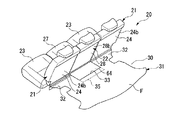
【解決手段】 車体前後方向に二列以上のシートを有するとともに最後尾シートが三人掛けシートとされ、最後尾シートの中央シート22はシートバック28が前倒された状態で下方にダイブダウン収納可能とされており、また中央シート22が最後尾シートの両側部シートよりも後側に位置するV字レイアウトが可能とされていて、さらにトランクフロア35が中央シート22とともにスライド可能とされている。
【選択図】 図9PROBLEM TO BE SOLVED: To provide a vehicle seat that can be comfortably arranged in a luggage compartment as required, and can be comfortably seated on three persons by a rear seat.
SOLUTION: Two or more rows of seats are provided in the longitudinal direction of the vehicle body, the rearmost seat is a three-seat seat, and the central seat 22 of the rearmost seat is dive-down stored downward with a seatback 28 tilted forward. In addition, a V-shaped layout is possible in which the central seat 22 is located on the rear side of both side seats of the rearmost seat, and the trunk floor 35 is slidable together with the central seat 22. .
[Selection] Figure 9
Description
本発明は、荷室アレンジが可能な車両用シート構造に関する。 The present invention relates to a vehicle seat structure that can be arranged in a luggage compartment.
車両の最後尾シートと荷室フロアとの間に荷室フロアよりも凹む凹部がある場合に、この凹部を収納部として利用するものであって、最後尾シートに荷室フロアとの間に架設されて凹部つまり収納部を覆うボードを回動可能に連結させる構造がある(特許文献1参照)。 When there is a recess that is recessed from the luggage compartment floor between the rear seat and the cargo compartment floor of the vehicle, this concave portion is used as a storage part, and is installed between the cargo floor and the rear seat. There is a structure in which a board that covers the recess, that is, the storage portion is rotatably connected (see Patent Document 1).
また、車両の最後尾シートのシートクッションを前端部を中心に回動可能とし、シートクッションを回動させた状態でシートバックを前倒させることでトランクルームを広げる場合に、シートバックと荷室フロアとの間に生じる荷室フロアよりも凹む凹部を、シートバックに連結されたボードを荷室フロアとの間に架設することで覆って、荷室フロアの段差をなくす構造がある(特許文献2参照)。
ところで、近年、車両の商品価値を高めるために、定員分の人数が乗車した場合であっても快適な居住性を得ることができ、また乗車人数が少ない場合には、必要に応じて多彩な荷室アレンジ等を可能とすることが要求されているが、上記の最後尾シートでは、荷室アレンジは可能であるものの快適に三人掛けをすることはできなかった。 By the way, in recent years, in order to increase the commercial value of vehicles, it is possible to obtain comfortable living even when the number of passengers is on board, and when the number of passengers is small, there are various as required. Although it is required that the luggage compartment can be arranged, the above-mentioned rear seat can perform the luggage compartment arrangement, but cannot comfortably carry three persons.
したがって、本発明は、必要に応じて荷室アレンジを可能とした上で、最後尾シートで快適に三人掛けをすることができる車両用シートの提供を目的とする。 Accordingly, an object of the present invention is to provide a vehicle seat that can be comfortably arranged in a luggage compartment as required and can be comfortably seated on three persons by the rear seat.
上記目的を達成するために、請求項1に係る発明は、車体前後方向に二列以上のシート(例えば実施形態における一列目シート10および二列目シート20)を有するとともに最後尾シート(例えば実施形態における二列目シート20)が三人掛けシートとされ、該最後尾シートの中央シート(例えば実施形態における中央シート22)はシートバック(例えば実施形態におけるシートバック28)が前倒された状態で下方にダイブダウン収納可能とされており、また前記中央シートが前後スライド可能であって前記最後尾シートの両側部シート(例えば実施形態における側部シート21)よりも後側に位置するV字レイアウトが可能とされていて、さらにトランクフロア(例えば実施形態におけるセンタフロアリッド35)が前記中央シートとともにスライド可能とされていることを特徴としている。
In order to achieve the above object, the invention according to claim 1 includes two or more rows of seats (for example, the
請求項2に係る発明は、請求項1に係る発明において、前記側部シートのシートバック(例えば実施形態におけるシートバック24)が前倒可能であることを特徴としている。 The invention according to claim 2 is characterized in that, in the invention according to claim 1, the seat back of the side seat (for example, the seat back 24 in the embodiment) can be moved forward.
請求項3に係る発明は、請求項1または2に係る発明において、前記最後尾シートの一列前のシート(例えば実施形態における一列目シート10)の中央シート(例えば実施形態における中央シート12)はシートバックが前倒可能であることを特徴としている。
The invention according to claim 3 is the invention according to claim 1 or 2, wherein the central sheet (for example, the
請求項1に係る発明によれば、最後尾シートを中央シートが両側部シートよりも後側に位置するV字レイアウトとすることで、三人掛けをしても乗員同士の肘や肩の干渉を防止でき、よって、最後尾シートで快適に三人掛けをすることができる。また、最後尾シートの中央シートをそのシートバックを前倒させてダイブダウン収納させるとともに、このとき中央シートとともにトランクフロアをスライドさせて、中央シートのスライドのため中央シートの後側に生じる荷室フロアよりも凹む凹部をトランクフロアで覆うことで、荷室フロアの段差をなくして略フラットな荷室を車体前方に広げることになり、長尺物も搭載可能になる。したがって、多彩な荷室アレンジが可能となる。 According to the first aspect of the present invention, the rear seat has a V-shaped layout in which the central seat is located on the rear side of the both side seats. Therefore, it is possible to comfortably hang up to three persons with the rear seat. In addition, the center seat of the rearmost seat is dive-down stored with its seat back forward, and at this time, the trunk floor is slid along with the center seat, and the cargo room generated behind the center seat for sliding the center seat By covering the concave portion recessed from the floor with the trunk floor, the step of the cargo compartment floor is eliminated and a substantially flat cargo compartment is widened to the front of the vehicle body, and a long object can be mounted. Therefore, a variety of luggage compartment arrangements are possible.
請求項2に係る発明によれば、最後尾シートの側部シートのシートバックが前倒可能であることから、最後尾シートの中央シートをそのシートバックを前倒させてダイブダウン収納させるとともに側部シートのシートバックを前倒状態とすることで荷室をさらに広げることができる。したがって、さらに多彩な荷室アレンジが可能となる。 According to the invention of claim 2, since the seat back of the side seat of the rearmost seat can be moved forward, the center seat of the rearmost seat is dive-down stored while the seat back is moved forward. The cargo space can be further expanded by bringing the seat back of the front seat to the forward state. Therefore, more various luggage arrangements are possible.
請求項3に係る発明によれば、最後尾シートの一列前のシートの中央シートもシートバックが前倒可能であることから、最後尾シートの中央シートをそのシートバックを前倒させてダイブダウン収納させるとともに最後尾シートの一列前のシートの中央シートもシートバックを前倒状態とすることで、荷室が車体前方にさらに広がり、さらに長い長尺物も搭載可能となる。したがって、より一層多彩な荷室アレンジが可能となる。 According to the third aspect of the invention, since the seat back of the center seat of the seat one row before the last seat can be moved forward, the center seat of the tail seat can be dive down with the seat back forward. When the seat is stored and the center seat of the seat in front of the last seat is also placed in the front-back state, the luggage compartment further expands in front of the vehicle body, and a longer object can be mounted. Therefore, a much more diverse arrangement of luggage can be achieved.
本発明の一実施形態の車両用シート構造を図面を参照して以下に説明する。なお、以下の説明において用いる前後左右は車体における前後左右である。 A vehicle seat structure according to an embodiment of the present invention will be described below with reference to the drawings. Note that the front, rear, left and right used in the following description are front, rear, left and right in the vehicle body.
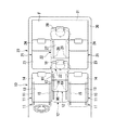
本実施形態の車両用シート構造は、図1に示すように、前から一列目の一列目シート10が左右両側に配置される一対の側部シート11とこれら側部シート11の間に配置される中央シート12とを有する3人掛けとされ、前から二列目の二列目シート20も左右両側に配置される一対の側部シート21とこれら側部シート21の間に配置される中央シート22とを有する3人掛けとされ、二列目シート20の直後位置に荷室30が設けられた6人乗りのものである。ここで、本実施形態では車体前後方向に二列のシート10,20が設けられているため、二列目シート20が最後尾シートとなり、一列目シート10がその一列前のシートとなる。
As shown in FIG. 1, the vehicle seat structure of the present embodiment is disposed between a pair of
一列目シート10の左右一対の側部シート11は、それぞれ、シートクッション13とシートバック14とを有しており、それぞれ単独で、シートクッション13の下側に設けられたスライド機構15によって前後スライド可能となっている。
The pair of left and
一列目シート10の両側部シート11の間に設けられる中央シート12は、シートクッション17とシートバック18とを有しており、シートクッション17の下側に設けられたスライド機構19によって単独で前後スライド可能となっている。なお、中央シート12のシートバック18は、ほぼ水平に沿う状態となってシートクッション17のほぼ全面に載置されるように前倒可能とされている。
The
ここで、中央シート12はスライド機構19による前後スライドの範囲が側部シート11のスライド機構15によるスライド範囲に対し後側にずれており、中央シート12は一対の側部シート11と前端部同士を合わせた位置から後方範囲でのみ前後スライド可能とされ、一対の側部シート11は中央シート12と前端部同士を合わせた位置から前方範囲でのみ前後スライド可能とされている。また、中央シート12のスライド機構19によるスライド範囲は、側部シート11のスライド機構15によるスライド範囲よりも大きく設定されている。
Here, the
具体的には、図1に二点鎖線で示すように、一対の側部シート11をスライド機構15により前端位置に位置させるとともに中央シート12をスライド機構19により前端位置に位置させると、一対の側部シート11よりも中央シート12が所定量後側にずれることになり、V字レイアウトとなる。
Specifically, as shown by a two-dot chain line in FIG. 1, when the pair of
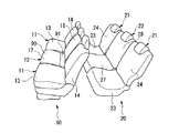
また、図1に実線で示すように両側の側部シート11をスライド機構15により後端位置に位置させるとともに、図1に二点鎖線で示すように中央シート12をスライド機構19により前端位置に位置させると、図2にも示すように、両側の側部シート11と中央シート12とが前後に位置を合わせる直線レイアウトになる。
Further, the
さらに、図1に二点鎖線で示すように両側の側部シート11をスライド機構15により前端位置に位置させるとともに、図1に実線で示すように中央シート12をスライド機構19により後端位置に位置させると、一対の側部シート11よりも中央シート12が所定量後側にずれることになり、V字レイアウトとなる。
Further, the
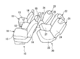
加えて、図1に実線で示すように、両側の側部シート11をスライド機構15により後端位置に位置させるとともに中央シート12をスライド機構19により後端位置に位置させると、図3にも示すように、一対の側部シート11よりも中央シート12が所定量後側にずれることになり、V字レイアウトとなる。
In addition, as shown by a solid line in FIG. 1, when the
二列目シート20の左右一対の側部シート21は、それぞれ、シートクッション23とシートバック24とを有しており、乗員の着席が可能な着席可能状態では位置固定すなわち前後スライド不可となっている。なお、両側部シート21のシートバック24は、ほぼ水平に沿う状態となってシートクッション23のほぼ全面に載置されるように前倒可能とされている。また、両側部シート21はシートバック24の前倒に連動して下方にダイブダウン収納可能とされている。
The pair of left and
二列目シート20の両側部シート21の間に設けられる中央シート22は、シートクッション27とシートバック28とを有しており、シートクッション27の下側に設けられたスライド機構29によって単独で前後スライド可能となっている。なお、中央シート22のシートバック28は、ほぼ水平に沿う状態となってシートクッション27のほぼ全面に載置されるように前倒可能とされている。また、中央シート22はシートバック28の前倒に連動して下方にダイブダウン収納可能とされている。
The
ここで、中央シート22はスライド機構29による前後スライドの範囲が位置固定の側部シート21から後側に延びており、中央シート22は一対の側部シート21と前端部同士を合わせた位置から後方範囲でのみ前後スライド可能とされている。
Here, the
具体的には、図1に二点鎖線で示すように、中央シート22をスライド機構29により前端位置に位置させると、図2にも示すように、両側の側部シート21と中央シート22とが前後に位置を合わせる直線レイアウトになる。
Specifically, as shown by a two-dot chain line in FIG. 1, when the
また、図1に実線で示すように、中央シート22をスライド機構29により後端位置に位置させると、一対の側部シート21よりも中央シート22が所定量後側にずれることになり、図3にも示すように、V字レイアウトとなる。
Further, as shown by a solid line in FIG. 1, when the
二列目シート20のスライド不可な両側部シート21は、図4および図5の着席可能状態および図6のダイブダウン収納状態に示すように、シートバック24の前倒に連動してシートクッション23が下方に沈み込むダイブダウン収納が可能とされている。両側部シート21は、それぞれシートバック24の背面24bの下部に、荷室フロアFを構成するフロアマット31の両側部延出部32の前端部が連結されており、前倒に連動するダイブダウン収納状態で側部シート21の後方に生じるであろう荷室フロアFよりも下方に凹む凹部をこのフロアマット31の側部延出部32で覆うことで荷室フロアFの段差をなくすようになっている。このとき、ダイブダウン収納状態にある側部シート21もそのシートバック24の背面24bが荷室フロアFとほぼ同一平面上に配置されることになる。
As shown in the seatable state of FIGS. 4 and 5 and the dive-down storage state of FIG. Dive down storage is possible in which sinks downward. The both
二列目シート20の中央シート22は、図4の着席可能状態でのスライド前端位置から図5の着席可能状態でのスライド後端位置までの間で前後スライド可能であり、また、図4の着席可能状態でのスライド前端位置および図6のダイブダウン収納状態に示すように、スライド前端位置からシートバック28が前倒し、この前倒に連動してシートクッション23が前方に移動しつつ下方に沈み込むダイブダウン収納が可能とされている。
The
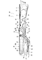
ここで、中央シート22は前後スライド可能とされていることから、荷室フロアFに敷設されたフロアマット31には、スライドを許容するための開口部33が両側部延出部32の間に形成されており、またこの開口部33の下側は中央シート22のスライドを許容するために荷室フロアFよりも下側で広がる図7に示す空間34となっている。そして、この開口部33を閉塞させることで空間34の上方開放を防止する板状のセンタフロアリッド(トランクフロア)35が、中央シート22に一体的にスライド可能に連結されている。このセンタフロアリッド35は、荷室フロアFの一部を構成するもので、中央シート22とともにスライド移動することで常に開口部33を閉塞させる。
Here, since the
次に、二列目シート20の前後スライド可能かつダイブダウン収納可能な中央シート22についてさらに説明する。
Next, the
二列目シート20の中央シート22は、図7に示すように、車体前側の低位フロア36と、この低位フロア36より高い車体後側の高位フロア37とが隣接して構成される段差フロア38に設けられている。また、高位フロア37の後方には荷室フロアFの下側に設けられてスペアタイヤ39を収納する床下収納部40が設けられ、この床下収納部40を覆いつつ荷室フロアFを形成するリヤフロアリッド41が高位フロア37よりもさらに高い位置に設けられている。
As shown in FIG. 7, the
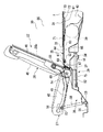
中央シート22のシートバック28は、クッション性を有し乗員の背部を支承するシートバック本体45と、このシートバック本体45を保持するシートバックフレーム46とを有している。また、中央シート22のシートクッション27は、クッション性を有し乗員の臀部を支承するシートクッション本体48と、このシートクッション本体48を保持するシートクッションフレーム49とを有している。
The seat back 28 of the
そして、高位フロア37上には、車体前後方向に沿うシートレール51が左右に離間して一対設けられており、これらシートレール51は、それぞれ前後方向にのみスライド可能にスライダ52を保持している。これらシートレール51およびスライダ52はスライド機構29を構成している。
A pair of seat rails 51 along the longitudinal direction of the vehicle body are provided on the
シートバックフレーム46は、その一端側が左右方向に中心軸線を配置した回動軸54を介してスライダ52に支持されており、これにより回動軸54を中心に略鉛直に沿う立設状態から前傾可能となっている。その結果、シートレール51で案内されてスライドするスライダ52にシートバック28が前傾可能に軸支されている。
The seat back
立設状態にあるシートバックフレーム46の回動軸54よりも所定量上側となる位置に、左右方向に中心軸線を配置した支持軸55が取り付けられており、支持軸55には、シートクッションフレーム49の後部が回動可能に軸支されている。シートクッションフレーム49は、支持軸55から下方に延出したのち前方に延出する概略形状をなしている。
A
シートクッションフレーム49の前端には支持部材56が固定されており、支持部材56には、左右方向に中心軸線を配置した回動軸57を介してリンクアーム58の一端が回動可能に連結されている。このリンクアーム58の他端側は、低位フロア36に設けられたフロア支持部59に回動可能に支持されている。これにより、シートクッションフレーム49の前部が低位フロア36とリンク結合されている。
A
そして、シートバック本体45の下部およびスライド機構29のスライダ52に、上記したセンタフロアリッド35が連結されている。このセンタフロアリッド35は、スライダ52から後方かつ上方に斜めに延出する連結部61の延出先端側に前端部下側の係合部62が連結された板状の変形困難なリッド本体63と、このリッド本体63の後端部の下面から上面全部を覆ってリッド本体63よりも前方まで延出する変形容易な表皮材64とを有している。なお、センタフロアリッド35において、リッド本体63および表皮材64のリッド本体63に貼付された部分が変形困難な板状部65とされている。
The
また、表皮材64のリッド本体63から前側に延出する部分には裏側に変形容易な補強材67が貼付されており、センタフロアリッド35は、リッド本体63のないこの部分が変形容易な易変形部68とされている。この易変形部68のリッド本体63に対し反対側が樹脂クリップ69でシートバック28の背面28bの下部に固定されている。ここで、補強材67のリッド本体63に対し反対側の端部に裏側に突出するように樹脂クリップ69が取り付けられており、表皮材64のリッド本体63に対し反対側の端部が、樹脂クリップ69の表面側を覆った後、補強材67のリッド本体63に対し反対側の端部の裏側に回り込みかつ樹脂クリップ69を突出させるように折り返されている。
Further, an easily deformable reinforcing
センタフロアリッド35は、リッド本体63を含む板状部65が、その前端部の係合部62においてスライダ52から延びる連結部61に連結されるとともに、その後部が中央シート22の後方にある上記したリヤフロアリッド41の開口部33の縁部の上側に重ねられている。そして、センタフロアリッド35およびリヤフロアリッド41の上側に上記したフロアマット31が敷設されている。このフロアマット31は、表皮材71の下面であってセンタフロアリッド35の板状部65と重なり合う部分に板材72が貼付され、この板材72の後側にも若干離間して板材73が貼付されている。
In the
次に、上記中央シート22の作動について説明する。
まず、通常の乗員が着座可能な着席可能状態について説明する。
Next, the operation of the
First, a seatable state where a normal occupant can be seated will be described.
着席可能状態においては、シートバック28が立設状態で図示せぬロック機構によりスライダ52に対し固定されている。このロック機構はシートバック28を着座可能な着座姿勢でスライダ52に固定可能および固定解除可能となっている。
In the seatable state, the seat back 28 is fixed to the
この着席可能状態において、スライダ52がシートレール51に沿って摺動することになるが、スライダ52は、スライドロック機構75によりシートレール51に対し複数の位置において固定可能および固定解除可能となっている。
In the seatable state, the
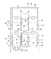
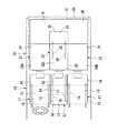
そして、スライダ52が、例えば図5および図8に示すようにスライド範囲の後端位置に位置する状態から図4および図7に示すようにスライド範囲の前端位置に位置する状態までシートレール51で案内されてスライドすると、スライダ52に固定された状態のシートバック28はそのままの姿勢でスライドする一方、シートバック28の支持軸55に回動可能に連結されたシートクッション27は、前部の回動軸57に回動可能に連結されたリンクアーム58を、フロア支持部59を中心に回動させることにより、前部側を若干円弧状の軌跡を描かせるように上下させながらスライドする。また、後方にスライドする場合は上記とは逆の作動を行う。
Then, for example, as shown in FIGS. 5 and 8, the
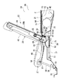
このように、中央シート22が前後にスライドすると、中央シート22のシートバック28およびスライダ52から延びる連結部61に連結されたセンタフロアリッド35は、その板状部65が、前端の係合部62において連結部61に支持され後端部がリヤフロアリッド41で支持された状態で略水平状態を維持したまま中央シート22と一体的にスライドすることになり、この板状部65と中央シート22との間の易変形部68も中央シート22とともにスライドする。これにより、中央シート22のスライドを許容するためにその下部の後側に形成される空間34がフロアマット31の開口部33を介して上方に開口した場合に生じる、荷室フロアFよりも下方に凹む凹部を、中央シート22のスライド位置にかかわらずセンタフロアリッド35が覆って閉塞させることになり、その結果、荷室フロアFに対し生じる段差をなくすことになる。なお、センタフロアリッド35の易変形部68は、長さに余裕が持たされており折り曲げられている。このため、シートバック28の角度調整でシートバック28への取付位置が係合部62に対し変動しても長さの余裕分で対応する。
As described above, when the
次に、ダイブダウン収納状態について説明する。
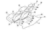
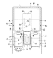
スライダ52が、図4および図7に示すようにスライド範囲の前端位置に位置する状態で、ロック機構によるロックを解除すると、図示せぬスプリングの付勢力でシートバック28が回動軸54を中心に回動して前倒する。すると、シートバック28において回動軸54よりも上側に位置していた支持軸55が前側かつ下側に移動し、その結果、図9に示すように、シートクッションフレーム49は、支持軸55に連結されている後部側が前側かつ下側に移動するとともに、前部の回動軸57に回動可能に連結されたリンクアーム58がフロア支持部59を中心に前傾することで、前部側も前側かつ下側に移動し、その結果、全体として前側かつ下側に移動して、保持するシートクッション本体48を前側かつ下側に移動させて低位フロア36側に落とし込む。このとき、シートバック28はシートクッション27に重なり合って背面28bが略水平となる。
Next, the dive down storage state will be described.
When the
このように、中央シート22がダイブダウンすると、センタフロアリッド35は、前端位置から移動していないスライダ52の連結部61に連結された板状部65がその前端の係合部62が連結部61に支持され後端部がリヤフロアリッド41で支持された状態で略水平状態を維持する一方、折り曲げられていた易変形部68が、シートバック28への取付位置が係合部62に対し離れることで広がり、平面状になって係合部62とシートバック28とを結ぶ。これにより、中央シート22のスライドを許容するためにその下部の後側に形成される空間34がフロアマット31の開口部33を介して上方に開口した場合に生じる、荷室フロアFよりも下方に凹む凹部を、ダイブダウン収納状態においてもセンタフロアリッド35が覆って閉塞させることになり、その結果、荷室フロアFに対し生じる段差をなくすことになる。また、ダイブダウン収納状態にある中央シート22はそのシートバック28の背面28bが荷室フロアFとほぼ同一平面上に配置されることになる。
As described above, when the
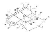
このように、二列目シート20の中央シート22を前倒状態でダイブダウン収納させると、図10に示すように略フラットな荷室スペース66は車幅方向の中央部において前方に拡大することになり、また、二列目シート20の側部シート21を前倒状態でダイブダウン収納させると、略フラットな荷室スペース66は車幅方向の側部において前方に拡大することになり、これらを合わせれば、図11に示すように、略フラットな荷室が車幅方向の全体において前方に拡大することになる。
In this way, when the
次に、一列目シート10の中央シート12について説明する。
一列目の中央シート12は、図12および図13に示すように、そのシートフレーム80においてスライド機構19に支持されており、シートフレーム80は、前後方向に沿う下部延在部81と下部延在部81の前端部から上方に突出する前部上方突出部82と下部延在部81の後端部から上方に延出する後部上方延出部83とを備えた一対の側部フレーム84を有している。中央シート12のシートバック18は、下部側が左右方向に沿う軸線を中心として回動可能となるように側部フレーム84の後部上方延出部83の上部に支持軸86を介して支持されている。
Next, the
As shown in FIGS. 12 and 13, the
ここで、上記したように、一列目の中央シート12においてもシートバック18は、ほぼ水平に沿う状態でシートクッション17のほぼ全面に載置される前倒可能となっているが、前倒状態で上面となるシートバック18の背面18bにはバックテーブル88が設けられている。このバックテーブル88は周縁部の高さが若干高くされており物品を安定的に載置させることが可能となっている。
Here, as described above, even in the
また、この中央シート12のシートクッション17は、前側分割体90と後側分割体91とに分割されている。後側分割体91は、略直方体形状をなしており、側部フレーム84の下部延在部81の後部側に車幅方向の両端側が載置されるようにしてシートフレーム80に固定されている。
Further, the
前側分割体90は、左右方向に沿う軸線を中心として回動可能となるように側部フレーム84の前部上方突出部82の上部に支持軸92を介して支持されている。
The front divided
前側分割体90は、略直方体形状をなしており、座面90aを上側にした状態で、後端下部の車幅方向における両端部がシートフレーム80の下部延在部81に載置され、後端下部の左右方向の中間部が側部フレーム84間に架設されたクッショントレー93に載置されるようになっている。ここで、座面90aを上側にした状態で、前側分割体90は、後側分割体91に隙間なく接触するとともに、後側分割体91の座面91aと自らの座面90aとをほぼ連続させる状態となる。つまり、前側分割体90と後側分割体91とは、この状態がシートクッション17を構成し乗員の着席を可能とする着席可能状態となる。
The front divided
前側分割体90は、上記着席可能状態における前端側が支持軸92によって回動可能に支持されており、この着席可能状態から後端部を引き上げることで、支持軸92すなわち左右方向に沿う軸線を中心に前方へ回動することになる。そして、前側分割体90は、回動により座面90aを下方に向けるように上下反転した状態で、図示せぬストッパに当接してそれ以上の回動が規制される。この状態が前側分割体90の前方回動状態である。
The front divided
前方回動状態にある上下反転後の前側分割体90の上面90b側には、複数のトレー部95が設けられており、これらのトレー部95は周縁部の高さが若干高くされることで物品の安定的な載置が可能となっている。また、前側分割体90が前方回動状態となることで前側分割体90よりも後側で露出するクッショントレー93も周縁部の高さが若干高くされることで物品の安定的な載置が可能とされている。なお、クッショントレー93の深さは比較的深くされており、高さの低い物品の収納が可能となっている。
A plurality of
また、クッショントレー93の下側であって両側部フレーム84の間には、前方に引き出し可能なアンダボックス97が設けられている。このアンダボックス97は上部が開口した箱状のもので物品の収納が可能となっている。
Further, an
そして、上記したように二列目シート20の中央シート22を前倒状態でダイブダウン収納させると、図10に示すように略フラットな荷室スペース66は車幅方向の中央部において前方に拡大することになり、これに加えて、二列目シート20の側部シート21を前倒状態でダイブダウン収納させると、図11に示すように、略フラットな荷室スペース66が車幅方向の全体において前方に拡大することになるが、さらに一列目シート10の中央シート12についてもシートバック18を前倒させることで、図14に示すように、さらに中央部の荷室スペース66を前方に拡大可能となっている。つまり、一列目シート10の中央シート12が適宜のスライド位置において前倒状態とされるとダイブダウン収納状態にある二列目シート20の中央シート22と近接してシートバック28,18の背面28b,18b同士を同一平面上に配置することになる。
Then, as described above, when the
勿論、一列目シート10の中央シート12のシートバック18を前倒状態とし、シートバック18の背面18bに設けられたバックテーブル88を使用しても良い。また、シートバック18を前倒状態とせずに、シートクッション17の前側分割体90を着席可能状態から反転させることで、クッショントレー93を使用したり、前側分割体90のトレー部95を使用したりすることも可能である。
Of course, the seat back 18 of the
以上に述べた本実施形態の車両用シート構造によれば、最後尾シートである二列目シート20を中央シート22が両側部シート21よりも後側に位置するV字レイアウトとすることで、三人掛けをしても乗員同士の肘や肩の干渉を防止でき、よって、最後尾シートで快適に三人掛けをすることができる。
According to the vehicle seat structure of the present embodiment described above, the second-
また、最後尾シートである二列目シート20の中央シート22をそのシートバック28を前倒させてダイブダウン収納させるとともにこのとき中央シート22とともにセンタフロアリッド35をスライドさせて、中央シート22のスライドのため中央シート22の後側に生じるであろう荷室フロアFよりも凹む凹部をセンタフロアリッド35で覆うことで、荷室フロアFの段差をなくして略フラットな荷室スペース66を車体前方に広げることになり、長尺物も搭載可能になる。したがって、多彩な荷室アレンジが可能となる。
Further, the
さらに、二列目シート20の側部シート21のシートバック24が前倒およびダイブダウン可能であり、中央シート22とのフラット化が可能であることから、二列目シート20の中央シート22をそのシートバック28を前倒させてダイブダウン収納させるとともに側部シート21のシートバック24を前倒させてダイブダウン収納させる状態とすることで略フラットな荷室スペース66をさらに広げることができる。したがって、さらに多彩な荷室アレンジが可能となる。
Further, since the seat back 24 of the
加えて、二列目シート20の一列前である一列目シート10の中央シート12もシートバック18が前倒可能であり、二列目シート20の中央シート22とのフラット化が可能であることから、二列目シート20の中央シート22をそのシートバック28を前倒させてダイブダウン収納させるとともに一列目シート10の中央シート12のシートバック18を前倒状態とすることで、略フラットな荷室スペース66が車体前方にさらに広がり、さらに長い長尺物も搭載可能となる。したがって、より一層多彩な荷室アレンジが可能となる。
In addition, the
なお、以上の実施形態においては、車体前後方向に二列のシートが配列された構造の場合に二列目シートの中央シートを前後スライド可能とすることでV字レイアウトを可能としまた二列目シートの中央シートをダイブダウン収納を可能として荷室アレンジの多様化を図ったが、例えば車体前後方向に三列のシートが配列された構造の場合には三列目シートに適用すれば良い。 In the above-described embodiment, in the structure in which two rows of seats are arranged in the longitudinal direction of the vehicle body, the center seat of the second row seat can be slid back and forth, thereby enabling a V-shaped layout and the second row. Although the center seat of the seats can be dive-down stored to diversify the luggage compartment arrangement, for example, in the case of a structure in which three rows of seats are arranged in the longitudinal direction of the vehicle body, it may be applied to the third row seats.
10 一列目シート(シート,一列前のシート)
12,22 中央シート
20 二列目シート(シート,最後尾シート)
21 側部シート
24,28 シートバック
35 センタフロアリッド(トランクフロア)
10 First row seat (sheet, previous row seat)
12, 22
21 Side seats 24, 28 Seat back 35 Center floor lid (trunk floor)
Claims (3)
The vehicle seat structure according to claim 1 or 2, wherein a seat back of the central seat of the seat in a row before the last seat can be moved forward.
Priority Applications (1)
| Application Number | Priority Date | Filing Date | Title |
|---|---|---|---|
| JP2004113234A JP2005297632A (en) | 2004-04-07 | 2004-04-07 | Vehicle seat structure |
Applications Claiming Priority (1)
| Application Number | Priority Date | Filing Date | Title |
|---|---|---|---|
| JP2004113234A JP2005297632A (en) | 2004-04-07 | 2004-04-07 | Vehicle seat structure |
Publications (1)
| Publication Number | Publication Date |
|---|---|
| JP2005297632A true JP2005297632A (en) | 2005-10-27 |
Family
ID=35329725
Family Applications (1)
| Application Number | Title | Priority Date | Filing Date |
|---|---|---|---|
| JP2004113234A Pending JP2005297632A (en) | 2004-04-07 | 2004-04-07 | Vehicle seat structure |
Country Status (1)
| Country | Link |
|---|---|
| JP (1) | JP2005297632A (en) |
Cited By (4)
| Publication number | Priority date | Publication date | Assignee | Title |
|---|---|---|---|---|
| JP2010132064A (en) * | 2008-12-03 | 2010-06-17 | Nissan Motor Co Ltd | Occupant crash protection |
| JP2012051528A (en) * | 2010-09-03 | 2012-03-15 | Mazda Motor Corp | Rear luggage compartment structure of vehicle |
| JP2014091371A (en) * | 2012-11-01 | 2014-05-19 | Toyota Boshoku Corp | Seat for vehicle |
| JPWO2014175240A1 (en) * | 2013-04-23 | 2017-02-23 | 本田技研工業株式会社 | vehicle |
-
2004
- 2004-04-07 JP JP2004113234A patent/JP2005297632A/en active Pending
Cited By (4)
| Publication number | Priority date | Publication date | Assignee | Title |
|---|---|---|---|---|
| JP2010132064A (en) * | 2008-12-03 | 2010-06-17 | Nissan Motor Co Ltd | Occupant crash protection |
| JP2012051528A (en) * | 2010-09-03 | 2012-03-15 | Mazda Motor Corp | Rear luggage compartment structure of vehicle |
| JP2014091371A (en) * | 2012-11-01 | 2014-05-19 | Toyota Boshoku Corp | Seat for vehicle |
| JPWO2014175240A1 (en) * | 2013-04-23 | 2017-02-23 | 本田技研工業株式会社 | vehicle |
Similar Documents
| Publication | Publication Date | Title |
|---|---|---|
| JP3768467B2 (en) | Vehicle seat structure | |
| JP3878099B2 (en) | Vehicle seat arrangement structure | |
| EP1449710B1 (en) | Seat device including a stowable auxiliary seat | |
| JP4717193B2 (en) | Car seat structure | |
| US7850246B2 (en) | Shingled thin seat construction for vehicle | |
| JP2009051455A (en) | Storage box structure for vehicles | |
| JP2005297632A (en) | Vehicle seat structure | |
| JP2005343322A (en) | Vehicle seat device | |
| JP4050247B2 (en) | Vehicle seat structure | |
| JP3730151B2 (en) | Vehicle seat | |
| JP2003276482A (en) | Vehicular rear seat | |
| JP2001001805A (en) | Vehicle center seat mounting structure | |
| JP4062026B2 (en) | Vehicle seat device | |
| JP2002067808A (en) | Vehicle luggage compartment structure | |
| JP4106657B2 (en) | Seat back structure | |
| JP4442389B2 (en) | Vehicle seat device | |
| JP2008284950A (en) | Vehicle seat device | |
| JP2004098724A (en) | vehicle | |
| JP3870805B2 (en) | Vehicle seat device | |
| JP4279297B2 (en) | Vehicle seat arrangement structure | |
| JP2014210536A (en) | Seat device | |
| JP3768494B2 (en) | Vehicle seat device | |
| JP4534913B2 (en) | Vehicle seat device | |
| JP2005075075A (en) | Vehicle seat | |
| JP2005247315A (en) | Vehicle seat structure |
Legal Events
| Date | Code | Title | Description |
|---|---|---|---|
| A977 | Report on retrieval |
Effective date: 20070823 Free format text: JAPANESE INTERMEDIATE CODE: A971007 |
|
| A131 | Notification of reasons for refusal |
Effective date: 20070904 Free format text: JAPANESE INTERMEDIATE CODE: A131 |
|
| A521 | Written amendment |
Effective date: 20071023 Free format text: JAPANESE INTERMEDIATE CODE: A523 |
|
| A02 | Decision of refusal |
Effective date: 20071211 Free format text: JAPANESE INTERMEDIATE CODE: A02 |