JP2005296519A - Pachinko game machine - Google Patents

Pachinko game machine Download PDF

Info

Publication number
JP2005296519A
JP2005296519A JP2004120658A JP2004120658A JP2005296519A JP 2005296519 A JP2005296519 A JP 2005296519A JP 2004120658 A JP2004120658 A JP 2004120658A JP 2004120658 A JP2004120658 A JP 2004120658A JP 2005296519 A JP2005296519 A JP 2005296519A
Authority
JP
Japan
Prior art keywords
display panel
game ball
ball
game
magnetic force
Prior art date
Legal status (The legal status is an assumption and is not a legal conclusion. Google has not performed a legal analysis and makes no representation as to the accuracy of the status listed.)
Pending
Application number
JP2004120658A
Other languages
Japanese (ja)
Inventor
Shuhei Kadoya
周平 門矢
Current Assignee (The listed assignees may be inaccurate. Google has not performed a legal analysis and makes no representation or warranty as to the accuracy of the list.)
Adachi Light Inc
Original Assignee
Adachi Light Inc
Priority date (The priority date is an assumption and is not a legal conclusion. Google has not performed a legal analysis and makes no representation as to the accuracy of the date listed.)
Filing date
Publication date
Application filed by Adachi Light Inc filed Critical Adachi Light Inc
Priority to JP2004120658A priority Critical patent/JP2005296519A/en
Publication of JP2005296519A publication Critical patent/JP2005296519A/en
Pending legal-status Critical Current

Links

Images

Landscapes

  • Pinball Game Machines (AREA)
  • Display Devices Of Pinball Game Machines (AREA)

Abstract

<P>PROBLEM TO BE SOLVED: To provide a pachinko game machine which raises fun in games much more. <P>SOLUTION: The pachinko game machine is provided with a thin display panel 25 which variably indicates patterns or the like in a game board 7 and the indication of the thin display panel 25 is visible through a transparent plate door frame 3, and the thin display panel 25 is provided at a predetermined distance from the transparent plate door frame 3 so that game balls can flow down in the front face of the thin display panel 25, and a magnetic means which makes magnetic attraction to the game balls in order to change the mode of the game balls flowing down is installed in the rear face of the thin display panel 25. <P>COPYRIGHT: (C)2006,JPO&NCIPI

Description

本発明は、磁性を有する遊技球を利用して遊技する弾球遊技機に関するものであり、特に可変表示装置を備えた弾球遊技機に関するものである。   The present invention relates to a ball game machine that uses a game ball having magnetism to play, and particularly to a ball game machine equipped with a variable display device.

従来、弾球遊技機としてのパチンコ遊技機には、遊技盤のほぼ中央部に複数種類の図柄を変動させる表示器を備えた可変表示装置が設けられている。そして、その可変表示装置は、表示器の表面に何の障害もないため、遊技球が表示器の前面を通過するようにすると、単に遊技球が表示器の前面をすぐに通過するだけで、遊技時間が極端に短くなってしまい、遊技性や娯楽性が損なわれるとの理由から表示器の上部に飾り部材を設けて、遊技球が表示器の前面を通過できないようにしている。   Conventionally, a pachinko gaming machine as a ball game machine is provided with a variable display device having a display for changing a plurality of kinds of symbols at a substantially central portion of the game board. And since the variable display device has no obstacle on the surface of the display, when the game ball passes through the front of the display, the game ball just passes immediately through the front of the display. A decoration member is provided on the upper part of the display for the reason that the game time becomes extremely short and the game and entertainment are impaired, so that the game ball cannot pass through the front of the display.

また、従来のパチンコ遊技機は、表示器の図柄の背景を変えてリーチ予告をしたり、表示器の表示がリーチ状態になったとき、キャラクタを登場させたりして遊技の興趣を盛り上げようとしていたが、すぐにマンネリ化して遊技者に飽きられてしまい、期待する程の効果がなかなか上がらなかった。そこで、表示器を大型化して表示内容を複雑化,多様化に対応させるようにした可変表示装置を備えたパチンコ遊技機が提案されている(例えば、特許文献1参照。)。
特開平10−277221号公報
In addition, conventional pachinko gaming machines try to increase the fun of gaming by changing the background of the design of the display to make a reach announcement, or when the display on the display is in a reach state, making characters appear. However, it quickly became rutted and bored by the player, and the expected effect was not easily improved. In view of this, a pachinko gaming machine has been proposed that includes a variable display device in which the display device is enlarged to make the display content more complicated and diversified (see, for example, Patent Document 1).
JP-A-10-277221

しかしながら、可変表示装置を大型化すると、可変表示装置の盤面上での占有面積が増えて遊技球の流下範囲が表示器の僅かな両側に限られてしまい、その流下態様が単調なものとなり、パチンコ遊技機本来の遊技球の流下を楽しむことができなくなっている。   However, when the size of the variable display device is increased, the occupied area on the surface of the variable display device is increased, and the flow range of the game ball is limited to only a few sides of the display, and the flow mode is monotonous, It is no longer possible to enjoy the flow of the original game balls of pachinko machines.

そこで、本発明は上記課題を解決するためになされたもので、表示器の前面に直接遊技球を流下させると共に、磁力によって遊技球の流下態様に変化を持たせ、遊技球の予想し得ない動きを楽しむようにした弾球遊技機を提供することを目的とするものである。   Therefore, the present invention has been made to solve the above problems, and the game ball is caused to flow directly to the front surface of the display, and the flow state of the game ball is changed by the magnetic force, so that the game ball cannot be predicted. The object is to provide a ball game machine that enjoys movement.

かかる目的を達成するために、請求項1記載の発明は、遊技盤に図柄等を可変表示する薄型表示パネルが設けられ、透明板扉枠を介して前記薄型表示パネルの表示を視認し得る弾球遊技機であって、前記薄型表示パネルの前面を遊技球が流下し得るように該薄型表示パネルを前記透明板扉枠から所定間隔隔てて設け、前記薄型表示パネルの後面に前記遊技球の流下態様を変動させるべく該遊技球に対して磁力を及ぼす磁力手段を設けたことを特徴とする。薄型表示パネルの前面を流下する遊技球の流下態様が磁力手段の磁力により変動されるようにした。磁力手段は薄型表示パネルにより遮蔽され、遊技者から視認できないようにするのが好ましい。   In order to achieve this object, the invention described in claim 1 is provided with a thin display panel that variably displays a symbol or the like on a game board, and a bullet which can visually recognize the display of the thin display panel through a transparent door frame. A ball game machine, wherein the thin display panel is provided at a predetermined distance from the transparent plate door frame so that a game ball can flow down the front surface of the thin display panel, and the game ball is placed on the rear surface of the thin display panel. Magnetic means for exerting a magnetic force on the game ball is provided to change the flow-down mode. The flow mode of the game ball flowing down the front surface of the thin display panel is changed by the magnetic force of the magnetic force means. The magnetic means is preferably shielded by a thin display panel so that it cannot be seen by the player.

請求項2記載の発明は、請求項1記載の発明において、前記磁力手段を前記薄型表示パネルの裏面側で可動させる電気的駆動源を設けたことを特徴とする。好ましくは薄型表示パネルの裏面に沿って可動させるのがよい。   According to a second aspect of the present invention, in the first aspect of the present invention, an electrical drive source is provided for moving the magnetic force means on the back side of the thin display panel. Preferably, it is movable along the back surface of the thin display panel.

請求項3記載の発明は、請求項1又は2記載の発明において、前記薄型表示パネルの上方に位置して該薄型表示パネルの前面に遊技球を導く球導入口を設けたことを特徴とする。   According to a third aspect of the present invention, in the first or second aspect of the present invention, a ball introduction port for guiding a game ball to the front surface of the thin display panel is provided above the thin display panel. .

請求項4記載の発明は、請求項3記載の発明において、前記球導入口に電気的駆動源により該球導入口を閉鎖する開閉部材を設けたことを特徴とする。   According to a fourth aspect of the present invention, in the third aspect of the present invention, an opening / closing member that closes the sphere inlet by an electric drive source is provided at the sphere inlet.

前記磁力手段は永久磁石からなり、永久磁石は遊技球の重さに優る吸着力を備えるのが好ましい。   The magnetic force means is made of a permanent magnet, and the permanent magnet preferably has an attractive force superior to the weight of the game ball.

前記磁力手段は電磁石からなり、前記磁力手段を吸着力を制御し得る電磁石とすることで、遊技球を重力に反して上昇させることも可能である。   The magnetic force means is composed of an electromagnet, and by making the magnetic force means an electromagnet capable of controlling the attractive force, it is possible to raise the game ball against gravity.

前記薄型表示パネルは液晶表示パネルであり、液晶表示パネルはバックライトを備え、該バックライトに前記磁力手段を設けるのが好ましい。   The thin display panel is a liquid crystal display panel, and the liquid crystal display panel preferably includes a backlight, and the magnetic force means is provided in the backlight.

前記薄型表示パネルは有機EL表示パネルであるのが好ましい。   The thin display panel is preferably an organic EL display panel.

前記磁力手段は前記薄型表示パネルの表示態様と対応して作動するようにするのが好ましい。薄型表示パネルの表示態様に連動して、磁力手段を可動させたり消励磁させることにより遊技球を移動させて、遊技の興趣を一段と高めることができる。   It is preferable that the magnetic force means operates in correspondence with the display mode of the thin display panel. In conjunction with the display mode of the thin display panel, the game ball can be moved by moving or deenergizing the magnetic force means, and the interest of the game can be further enhanced.

前記薄型表示パネルの前面に保護板を設けたり保護シートを貼着したりして、遊技球との接触により薄型表示パネルの表面が傷つかないようにするのが好ましい。   It is preferable to provide a protective plate or a protective sheet on the front surface of the thin display panel so that the surface of the thin display panel is not damaged by contact with the game ball.

前記薄型表示パネルの周縁に位置して入賞口を設け、可動自在に設けた磁力手段の磁力により吸着した遊技球を入賞口に導くようにするのが好ましい。このとき、入賞口に入賞した遊技球を検知する検知センサを設けるのがよい。   It is preferable that a winning opening is provided at the periphery of the thin display panel so that the game ball adsorbed by the magnetic force of the magnetic means provided movably is guided to the winning opening. At this time, it is preferable to provide a detection sensor for detecting a game ball won in the winning opening.

本発明に係る弾球遊技機は、複数の文字,記号,図柄等を可変表示する薄型表示パネルの後面に遊技球を吸着し得る磁力を持った永久磁石等からなる磁力手段を配置したので、薄型表示パネルの前面を流下する遊技球が磁石に吸着されて移動するため、遊技者は、遊技領域にて無重力状態であるかのように移動する遊技球の格別斬新な動きを楽しみ、パチンコ遊技の興趣を増大させることができる。   In the ball game machine according to the present invention, magnetic means comprising a permanent magnet having a magnetic force capable of attracting the game ball is arranged on the rear surface of the thin display panel that variably displays a plurality of characters, symbols, symbols, etc. Since the game ball flowing down the front of the thin display panel is attracted by the magnet and moved, the player enjoys a particularly innovative movement of the game ball that moves as if it is weightless in the game area, pachinko game Can increase interest.

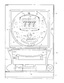
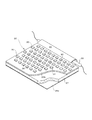
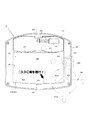
以下、本発明に係る実施例を図面と共に説明する。なお、本実施例は磁性を有する遊技球を使用して遊技する弾球遊技機としてパチンコ遊技機について説明する。図1は本発明のパチンコ遊技機の正面図である。パチンコ遊技機は機枠1の前面に前面枠2が開閉自在に装着され、その前面枠2の前面に透明板扉枠3と打球供給皿4を装着した前面板5とがそれぞれ開閉自在に蝶着されている。そして、その下方に打球供給皿4からの余剰球を貯留する余剰球受皿6が設けられている。   Embodiments according to the present invention will be described below with reference to the drawings. In this embodiment, a pachinko game machine will be described as a ball game machine that uses a game ball having magnetism. FIG. 1 is a front view of a pachinko gaming machine according to the present invention. The pachinko gaming machine has a front frame 2 mounted on the front of the machine frame 1 so that it can be opened and closed, and a front panel 5 fitted with a transparent plate door frame 3 and a hitting ball supply tray 4 on the front of the front frame 2. It is worn. And the surplus ball receiving tray 6 which stores the surplus ball from the hit ball supply tray 4 is provided therebelow.

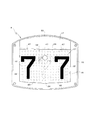
前記透明板扉枠3の後側に位置する前面枠2に保持枠を介して遊技盤7が装着され、該遊技盤7の前面には遊技領域7aを形成するガイドレール8が敷設されている。遊技領域7aの略中央には表示装置9が固着され、該表示装置9の直下に表示装置9を変動表示させる始動入賞口10が設けられ、その下方に入賞装置11が装着されている。さらに、遊技領域7aには一般入賞口12や打球の流下方向を変える風車13を配設すると共に、ガイドレール8の内側下端部にアウト口14を設けている。前記入賞装置11は、遊技客にとって有利な「大当り」等の特定遊技状態に、開閉扉11aを連続して開ける動作を繰り返し、所定数の入賞球を受け入れる公知的な装置である。   A game board 7 is mounted on the front frame 2 located on the rear side of the transparent plate door frame 3 via a holding frame, and a guide rail 8 forming a game area 7a is laid on the front surface of the game board 7. . A display device 9 is fixed substantially at the center of the game area 7a, a start winning opening 10 for variably displaying the display device 9 is provided immediately below the display device 9, and a winning device 11 is mounted below the start winning opening 10. Further, the game area 7 a is provided with a general winning opening 12 and a windmill 13 for changing the direction of the flow of the hit ball, and an out opening 14 is provided at an inner lower end portion of the guide rail 8. The winning device 11 is a well-known device that receives a predetermined number of winning balls by repeatedly opening and closing the door 11a in a specific gaming state such as “big hit” advantageous to the player.

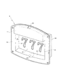
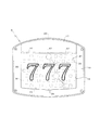
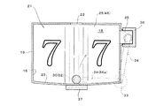
前記表示装置9は、図2乃至図4に示すようにほぼ中央に前後に開放する開口16が形成された取付基板15を有し、開口16の上方に位置して所定の厚みを有する飾り部材17が前方に突出して設けられ、開口16の後方に凹室18を形成した支持枠19を連設し、透明な保護板20を介して種々の数字,文字,図柄等の識別情報を変動可能に表示する可変表示器21が配設され、開口16から可変表示器21に表示される表示内容が視認できるようにしている。なお、保護板20に替えて可変表示器21の前面に保護シートを直接貼着するようにしてもよい。また、飾り部材17には遊技球が通過し得る大きさの球導入口22が形成され、球導入口22から飾り部材17内に流入する遊技球を、複数個所に設けた球導出口47から可変表示器21の前面に導くようにしており、凹室18下面は中央部に向かって緩やかに下傾し遊技球が自由に転動する遊動部23が形成され、該遊動部23のほぼ中央に遊技球を始動入賞口10等の所定箇所に向って誘導する誘導溝24が形成されている。なお、球導入口22は複数箇所に設けるようにしてもよい。   As shown in FIGS. 2 to 4, the display device 9 includes a mounting substrate 15 having an opening 16 that is open at the front and rear at substantially the center, and a decorative member that is positioned above the opening 16 and has a predetermined thickness. 17 is provided to project forward, and a support frame 19 in which a concave chamber 18 is formed behind the opening 16 is continuously provided, and identification information such as various numbers, letters, designs, etc. can be changed via a transparent protective plate 20. A variable display 21 is provided to display the display content displayed on the variable display 21 through the opening 16. A protective sheet may be directly attached to the front surface of the variable display 21 instead of the protective plate 20. Further, the decoration member 17 is formed with a ball introduction port 22 large enough to allow a game ball to pass through, and the game balls flowing into the decoration member 17 from the ball introduction port 22 are provided from a ball outlet port 47 provided at a plurality of locations. The lower surface of the concave chamber 18 is gently inclined downward toward the central portion to form a floating portion 23 where the game ball rolls freely. A guide groove 24 for guiding the game ball toward a predetermined location such as the start winning opening 10 is formed. In addition, you may make it provide the ball | bowl introduction port 22 in multiple places.

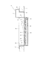
前記可変表示器21は、図柄等を可変表示する薄型表示パネルとしての液晶表示パネル25とバックライト26とを箱枠体48にユニット化して構成され、液晶表示パネル25をその裏側からバックライト26により照らすようにして、液晶表示パネル25に表示される識別情報を前面側から視認し得るようにしている。バックライト26は、所謂サイドライト方式であり、図5に示すように導光板27の上方に位置してランプ28が配設され、導光板27の裏面に反射フィルム29aが貼着されると共に、表面に拡散シートが29b配設されている。そして、拡散シート29b側に、液晶表示パネル25の前面を流下する遊技球に対して磁力を及ぼす磁力手段としての永久磁石30が斜め格子状に複数配設されている。この永久磁石30は、5mm程度の液晶表示パネル25を介して遊技球を吸着し得る磁力を有しており、液晶表示パネル25の前面を流下する遊技球の流下態様が磁力により変動されるようにしている。なお、磁力手段は、別途透光性を有する板部材に永久磁石30を配設するようにして、液晶表示パネル25とバックライト26との間に永久磁石30を配設した板部材を配置するようにしてもよい。また、バックライト26は所謂直下ライト式としてもよく、前面が開口した枠体の内側に光源としての蛍光管を蛇行状又は所定間隔を離して配設し、蛍光管と蛍光管との間に磁力手段として遊技球の重さに優る磁力を持った永久磁石30を複数配設するようにすればよい。さらに、バックライト26は面状の光源であってもLEDを用いたものであってもよい。   The variable display 21 is configured by unitizing a liquid crystal display panel 25 and a backlight 26 as a thin display panel for variably displaying symbols and the like into a box frame 48, and the liquid crystal display panel 25 is backlit from the back side. The identification information displayed on the liquid crystal display panel 25 can be viewed from the front side. The backlight 26 is a so-called side light system, and as shown in FIG. 5, a lamp 28 is disposed above the light guide plate 27, and a reflective film 29a is attached to the back surface of the light guide plate 27. A diffusion sheet 29b is disposed on the surface. On the diffusion sheet 29b side, a plurality of permanent magnets 30 as magnetic means for applying a magnetic force to the game balls flowing down the front surface of the liquid crystal display panel 25 are arranged in an oblique lattice shape. The permanent magnet 30 has a magnetic force capable of attracting a game ball via the liquid crystal display panel 25 of about 5 mm, and the flow-down mode of the game ball flowing down the front surface of the liquid crystal display panel 25 is changed by the magnetic force. I have to. In addition, the magnetic force means arrange | positions the plate member which provided the permanent magnet 30 between the liquid crystal display panel 25 and the backlight 26 so that the permanent magnet 30 may be arrange | positioned to the plate member which has translucency separately. You may do it. The backlight 26 may be of a so-called direct light type, and a fluorescent tube as a light source is arranged in a meandering manner or at a predetermined interval inside a frame having an open front, and the fluorescent tube is interposed between the fluorescent tube and the fluorescent tube. A plurality of permanent magnets 30 having a magnetic force superior to the weight of the game ball may be provided as magnetic means. Further, the backlight 26 may be a planar light source or an LED.

また、パチンコ遊技機には遊技内容を制御する主制御部を備えており、該主制御部は大当り設定及びはずれ設定等のゲームのプログラムが記憶された読み出し専用のROMと、入賞装置11の連続開閉回数(ラウンド数)等のデータを一時的に記憶する読み書き可能なRAMと、プログラムデータに基づきパチンコ遊技を実行するCPUを備えている。CPUは、遊技中に、遊技球が始動入賞口10に入賞すると、表示制御部に信号を出力して、表示装置9が表示する数字や図柄等の識別情報を変動表示させ、その表示態様が所謂2つの図柄が揃ってリーチ状態になり、所定時間後、予め決められた図柄が揃うと、遊技客にとって有利な特別遊技状態である「大当り」となって、入賞装置11の開閉扉11aを開動作させる。   In addition, the pachinko gaming machine is provided with a main control unit for controlling game contents, and the main control unit is a continuous read-only ROM in which game programs such as jackpot setting and loss setting are stored, and the winning device 11. A readable / writable RAM that temporarily stores data such as the number of times of opening / closing (number of rounds) and a CPU that executes a pachinko game based on program data are provided. During the game, when the game ball wins the start winning opening 10, the CPU outputs a signal to the display control unit to variably display the identification information such as numbers and symbols displayed on the display device 9. So-called two symbols come together to reach a reach state. After a predetermined time, when the predetermined symbols are gathered, a special game state advantageous to the player becomes a “big hit”, and the door 11a of the winning device 11 is opened. Open operation.

前記表示装置9は、遊技領域7aのほぼ中央に位置するように遊技盤7に開設した取付開口31に取付けられる。このとき、可変表示器21の表示領域のほぼ全域が視認可能な状態であり、遊技者からは磁力手段としての永久磁石30は液晶表示パネル25の存在によって遮蔽され視認できない状態にある。そして、上記構成の表示装置9が装着されたパチンコ遊技機は、遊技領域7aに打ち込まれた遊技球が始動入賞口10に入賞すると可変表示器21の図柄が変動し、所定時間後に停止した図柄表示が所定の図柄表示である場合には、「大当り」となり、入賞装置11が開放して遊技者にとって有利な遊技状態となる。また、遊技領域7aに打ち込まれた遊技球が表示装置9の球導入口22に入球すると、図3に示すように球導出口47から可変表示器21の前面に導かれて自然落下するが、液晶表示パネル25の後面に配設される永久磁石30の磁力によって遊技球が蛇行したり斜行したりして、今までにない特有な動きを遊技者に見せることができる。特に、遊技者からは磁力手段としての永久磁石30が視認されないため、予想し得ない遊技球の流下態様が遊技者に不思議な感じを抱かせて遊技の興趣を高めることができる。そして、凹室18下面に到達した遊技球は、遊動部23を自由に転動し、そのまま遊技盤7面に放出されるか誘導溝24によって始動入賞口10に向かって放出される。また、複数個の永久磁石30をN極とS極とが交互になるように列設することにより磁力の強い箇所が定間隔でできることから、遊技球はその磁力に吸着されステップ状の動きを伴って移動し、さらに特有の動きとなり得る。なお、実施例において永久磁石30を斜め格子状に設けるようにしたが、磁石の配列は実施例の態様に限定されるものではなく、永久磁石30をランダムに設けても連続状に設けてもよく、永久磁石30の配列によって遊技球の動きに様々な変化を及ぼすことができる。また、永久磁石30を枝分かれ状に配設するようにしてもよく、枝分かれ状となった複数本の経路により所定の位置に遊技球を導くことも可能となる。さらに、複数本の経路の終端に入賞口を形成することで、遊技球が自然流下に反して恰も入賞口に吸引されていくかのように見せることもできる。   The display device 9 is attached to the attachment opening 31 opened in the game board 7 so as to be located at the approximate center of the game area 7a. At this time, almost the entire display area of the variable display 21 is visible, and the permanent magnet 30 as magnetic means is shielded by the presence of the liquid crystal display panel 25 from the player and is not visible. In the pachinko gaming machine equipped with the display device 9 having the above-described configuration, the design of the variable display 21 fluctuates when the game ball driven into the game area 7a wins the start winning opening 10, and stops after a predetermined time. When the display is a predetermined symbol display, it becomes a “hit”, and the winning device 11 is opened to enter a gaming state advantageous to the player. Further, when a game ball that has been driven into the game area 7a enters the ball introduction port 22 of the display device 9, as shown in FIG. 3, the ball is guided from the ball outlet port 47 to the front surface of the variable display 21 and falls naturally. The game ball meanders or skews by the magnetic force of the permanent magnet 30 disposed on the rear surface of the liquid crystal display panel 25, so that the player can be shown a unique movement that has never existed. In particular, since the permanent magnet 30 as the magnetic means is not visually recognized by the player, the unintended flow of the game ball can make the player feel a mystery and enhance the interest of the game. Then, the game ball that has reached the lower surface of the concave chamber 18 rolls freely in the game unit 23 and is released as it is to the game board 7 surface or is released toward the start winning opening 10 by the guide groove 24. Further, by arranging a plurality of permanent magnets 30 so that N poles and S poles are alternately arranged, locations with strong magnetic force can be formed at regular intervals, so that the game ball is attracted by the magnetic force and moves stepwise. It moves with it and can be a more specific movement. In the embodiment, the permanent magnets 30 are provided in an oblique lattice shape. However, the arrangement of the magnets is not limited to the embodiment, and the permanent magnets 30 may be provided randomly or continuously. In many cases, the movement of the game ball can be changed by the arrangement of the permanent magnets 30. In addition, the permanent magnets 30 may be arranged in a branched shape, and it is possible to guide the game ball to a predetermined position through a plurality of branched routes. Furthermore, by forming a winning opening at the end of a plurality of paths, it is possible to make it appear as if the game ball is attracted to the winning opening against the natural flow.

なお、磁力手段を永久磁石30とした際に、磁力の強さ,汚れ等により遊技球が吸着されたままの状態になる可能性があるため、可変表示器21の前面側に吸着された状態の遊技球を解放する解除手段を設けるのが好ましい。解除手段は、例えば可変表示器21の前面に沿って棒状の可動体がモータ等の駆動源により回動又は上下左右に移動するように設けて、可変表示器21の前面に吸着された状態の遊技球を払い落すようにすればよい。この可動体は、変動表示の図柄停止毎等の所定間隔毎に可動させるようにすればよい。また、この可動体を単なる解除手段とすることなく、磁石に吸着される遊技球と関連させるようにして、例えば可動体に邪魔されることなくタイミングよく遊技球が誘導溝24等の所定位置に到達した際に、遊技者に特典が付与される等のゲーム性を持たせるようにしてもよい。   Note that when the magnetic force means is the permanent magnet 30, the game ball may remain adsorbed due to the strength of the magnetic force, dirt, etc., so that it is adsorbed on the front side of the variable display 21. It is preferable to provide release means for releasing the game ball. The release means is provided such that, for example, a rod-shaped movable body is rotated or moved up and down and left and right by a driving source such as a motor along the front surface of the variable display 21 and is attracted to the front of the variable display 21. What is necessary is just to drop a game ball. What is necessary is just to make this movable body move at predetermined intervals, such as every time the symbol of variable display is stopped. In addition, the movable body is associated with the game ball attracted by the magnet without using the movable body as a simple release means, for example, the game ball can be placed at a predetermined position such as the guide groove 24 without being disturbed by the movable body. You may make it give game characteristics, such as giving a privilege to a player, when reaching | attaining.

このように、遊技領域7aに打ち込まれた遊技球は、表示装置9の両脇ばかりではなく可変表示器21の前面にも導かれ、しかも可変表示器21の前面に導かれた遊技球は磁力手段により、遊技者に予想のできない動きをして流下する。そのため、その遊技球の流下態様が変化に富んで遊技の趣向性を高めることができ、遊技者は可変表示器21の表示を見ながら遊技球の流下態様を楽しむことができる。   In this way, the game ball that has been driven into the game area 7a is guided not only to the sides of the display device 9 but also to the front surface of the variable display device 21, and the game ball guided to the front surface of the variable display device 21 has a magnetic force. By means, the player moves down with unexpected movements. Therefore, the flow-down mode of the game ball is rich in change, and the game's preference can be enhanced, and the player can enjoy the flow-down mode of the game ball while viewing the display on the variable display 21.

図6は磁力手段を電磁石32とした実施例を示し、制御装置により電磁石32の吸着力を制御するようにしている。この実施例において電磁石32は前記実施例の永久磁石30と同様に、バックライト26の前面に格子状に近接して設けている。磁力手段を電磁石32として使用した場合は、そのオン・オフによって遊技球の動きを制御することができるので、複数並設した電磁石32を所定の順番で励磁させることにより、遊技球を所望方向に移動させることも可能となる。その場合、下方の電磁石32から上方の電磁石32の順に励磁させることで遊技球を重力に反して上昇させることも可能である。また、電磁石32の励磁により遊技球を任意に移動させることができるので、可変表示器21の表示態様と関連させて電磁石32を励磁させるようにしてもよい。例えば図6に示すように、可変表示器21の表示が左右の数字がそろった所謂「リーチ状態」のときに、所定の電磁石32を励磁させて遊技球を吸着させ、順次近接する他の電磁石32を励磁させて遊技球を移動させ、液晶表示パネル25に該遊技球の軌跡を表示させることができる。そして、その軌跡が他の表示図柄と同じ数字に描かれたら「大当り」となるようにすると、遊技者は液晶表示パネル25の前面を流下する遊技球の動きに注目することになる。このとき、恰も遊技球が液晶表示パネル25に図柄を描くように見せるため、制御装置により磁力を制御し得るようにして電磁石32の励磁力を強くし、大当り設定の時には最後までその吸着力を維持させ、はずれ設定の時には途中で電磁石32の励磁力を弱めるか消磁して遊技球を自然落下させ、遊技者には遊技球が落下したために外れたと思わせることができ、遊技者は遊技球の動きに期待感をこめて注目することになり、遊技の興趣が高められる。また、前記実施例では1個の遊技球の軌跡を液晶表示パネル25に表示するようにしたが、複数の遊技球の軌跡を表示するようにしてもよい。さらに、複数の電磁石32を吸着された遊技球が所定の図柄を表示するように励磁させ、複数の遊技球が可変表示器21の前面に並ぶことによって図柄,数字を直接表示させるようにしてもよい。例えば、所定時間内に電磁石32に吸着された遊技球によって所定の図柄,数字を表示できれば「大当り」となるようにすれば、途中で液晶表示パネル25の前面を流下する遊技球が、吸着された遊技球に当たって落としたりして、遊技客は何とか所定の図柄,数字にしようと必死になり遊技を楽しむことができる。   FIG. 6 shows an embodiment in which the electromagnet 32 is used as the magnetic force means, and the attraction force of the electromagnet 32 is controlled by the control device. In this embodiment, the electromagnet 32 is provided close to the front surface of the backlight 26 in a lattice shape, like the permanent magnet 30 of the above embodiment. When the magnetic force means is used as the electromagnet 32, the movement of the game ball can be controlled by turning it on and off, so that the game ball can be moved in a desired direction by exciting a plurality of electromagnets 32 arranged in a predetermined order. It can also be moved. In that case, it is also possible to raise the game ball against gravity by exciting the lower electromagnet 32 to the upper electromagnet 32 in this order. Further, since the game ball can be arbitrarily moved by exciting the electromagnet 32, the electromagnet 32 may be excited in association with the display mode of the variable display 21. For example, as shown in FIG. 6, when the display of the variable display 21 is a so-called “reach state” in which left and right numbers are aligned, a predetermined electromagnet 32 is excited to attract a game ball, and other electromagnets sequentially approaching each other The game ball can be moved by exciting 32 and the trajectory of the game ball can be displayed on the liquid crystal display panel 25. Then, if the trajectory is drawn in the same number as the other display symbols, the player will pay attention to the movement of the game ball flowing down the front surface of the liquid crystal display panel 25. At this time, since the game ball appears to draw a pattern on the liquid crystal display panel 25, the exciting force of the electromagnet 32 is strengthened so that the magnetic force can be controlled by the control device. When the setting is set to be off, the exciting force of the electromagnet 32 is weakened or demagnetized in the middle to cause the game ball to fall naturally, so that the player can think that it has come off because the game ball has fallen. This will increase the interest of the game. In the above embodiment, the trajectory of one game ball is displayed on the liquid crystal display panel 25, but the trajectories of a plurality of game balls may be displayed. Further, the plurality of electromagnets 32 are excited so that the game balls attracted display a predetermined symbol, and the plurality of game balls are arranged in front of the variable display 21 to directly display the symbols and numbers. Good. For example, if the game ball that is attracted to the electromagnet 32 within a predetermined time is displayed as a “big hit” if a predetermined symbol and number can be displayed, the game ball that flows down the front of the liquid crystal display panel 25 is attracted. By hitting the game ball and dropping it, the player can enjoy the game desperately trying to make a predetermined pattern or number.

また、図7に示した実施例は、磁力手段を電気的駆動源により可動自在に設けたものである。この実施例において電気的駆動源は正逆モータ33であり、該モータ33は図7に示すように可変表示器21の裏面側隅角に位置して設けられている。そして、磁力手段としての永久磁石30が可動体34のアーム34aの先端に設けられ、可動体34が一端をモータ軸に固設して、可動体34が液晶表示パネル25の後面に臨んで該液晶表示パネル25の裏面に沿って回動し得るように設けている。モータ33は、制御装置により所定範囲内を回動し得るように回転方向を制御している。また、凹室18の側方に可変表示器21の表面に沿って移動する遊技球が入賞し得る特別入賞口35が開設されると共に、該特別入賞口35に入賞球検知センサ36を設けている。常態で永久磁石30は、図7鎖線に示すように可変表示器21の表示領域から外れた特別入賞口35の後方に位置し、液晶表示パネル25の前面を流下する遊技球が無用に永久磁石30に吸着されないようにしており、正逆モータ33は所定条件のもとに駆動するようになっている。また、永久磁石30が位置する凹室18の遊動部23下面に該永久磁石30に吸着される遊技球の有無を検知する球検知センサ37を設けている。   In the embodiment shown in FIG. 7, the magnetic force means is movably provided by an electric drive source. In this embodiment, the electric drive source is a forward / reverse motor 33, and the motor 33 is provided at a corner on the back side of the variable display 21 as shown in FIG. 7. A permanent magnet 30 as magnetic means is provided at the tip of the arm 34a of the movable body 34. The movable body 34 has one end fixed to the motor shaft, and the movable body 34 faces the rear surface of the liquid crystal display panel 25. The liquid crystal display panel 25 is provided so as to be rotatable along the back surface. The motor 33 controls the direction of rotation so that the controller 33 can rotate within a predetermined range. In addition, a special winning opening 35 for opening a game ball moving along the surface of the variable display 21 is opened on the side of the concave chamber 18, and a winning ball detecting sensor 36 is provided in the special winning opening 35. Yes. In the normal state, the permanent magnet 30 is positioned behind the special winning opening 35 deviated from the display area of the variable display 21 as indicated by a chain line in FIG. 7, and the game ball flowing down the front surface of the liquid crystal display panel 25 is used as a permanent magnet. The forward / reverse motor 33 is driven under a predetermined condition. In addition, a ball detection sensor 37 that detects the presence or absence of a game ball attracted to the permanent magnet 30 is provided on the lower surface of the idler 23 of the concave chamber 18 where the permanent magnet 30 is located.

上記構成の磁力手段の実施例は、例えば、前述したように可変表示器21の表示が左右の数字がそろった所謂「リーチ状態」のときに、正逆モータ33を駆動して可動体34を回動させて、図7点線に示すように永久磁石30を凹室18の遊動部23に位置させる。そして、遊技球が永久磁石30に吸着され球検知センサ37によって確認された後に、モータ33を駆動して可動体34を可動させて吸着した遊技球を円弧状に移動させ、凹室18の側方に開設した特別入賞口35に導いて、入賞球検知センサ36によって遊技球が検知されると可変表示器21の図柄表示が揃い「大当り」となる。このようにすると、遊技者は遊技球が特別入賞口35に入賞するかどうか緊張感が高まり、遊技の興趣性を向上させることができる。また、リーチ状態となって所定時間経過しても球検知センサ37で遊技球が検知されないときには、可変表示を任意に停止させるようにすればよい。この実施例において、磁力手段を永久磁石30としたが電磁石32としてもよく、磁力手段を電磁石32とすることで遊技球の吸着力を変更できるため、電磁石32の磁力を弱めて途中で遊技球を落下させて、はずれにすることもでき、特別入賞口35への入賞確率を制御することができる。   In the embodiment of the magnetic force means having the above configuration, for example, when the display of the variable display 21 is in a so-called “reach state” in which the left and right numbers are aligned, the forward / reverse motor 33 is driven to move the movable body 34. By rotating, the permanent magnet 30 is positioned on the free-moving portion 23 of the concave chamber 18 as shown by the dotted line in FIG. Then, after the game ball is attracted to the permanent magnet 30 and confirmed by the ball detection sensor 37, the motor 33 is driven to move the movable body 34 to move the attracted game ball in an arc shape. When the game ball is detected by the winning ball detection sensor 36 after being led to the special winning opening 35 opened in the direction, the symbol display of the variable display 21 is aligned and a “hit” is achieved. If it does in this way, a player will be tense whether a game ball will win the special winning opening 35, and can improve the interest property of a game. In addition, if a game ball is not detected by the ball detection sensor 37 even after a predetermined time has elapsed in the reach state, the variable display may be arbitrarily stopped. In this embodiment, the magnetic force means is the permanent magnet 30, but it may be the electromagnet 32. Since the magnetic force means can be changed to the electromagnet 32, the attraction force of the game ball can be changed. Can be dropped, and the winning probability to the special winning opening 35 can be controlled.

また、磁力手段を可動自在とすることで、可変表示器21の表示態様と関連づけさせることができる。例えば、磁力手段を電磁石32として、該電磁石32を励磁して吸着される遊技球を野球のボールやゴルフボールにみたてると共に、特別入賞口35をホームランゾーンやグリーンのカップにみたてる構成とする。そして、液晶表示パネル25の表示がリーチ状態となって電磁石32を励磁させて、吸着した遊技球が球検知センサ37で検知されると、制御装置により表示画面を野球場又はゴルフ場の画面に切替えて、モータ33を駆動して可動体34が回動させ、可動体34の回動に伴って電磁石32に吸着された遊技球が、ホームランゾーンやグリーンのカップにみたてた特別入賞口35に入球するかどうかを楽しむことができる。さらに、可変表示器21の前面側で電気的駆動源の駆動により可動する可動部材を設けるのが好ましく、例えばこの可動部材を野球のバットやゴルフのクラブに模して、所定条件のもとで可動部材を可動させ、恰も可動部材が電磁石32に吸着された遊技球を打ったかのようなタイミングで遊技球を移動させるようにすることで、遊技者の興趣を向上させることができる。また、可動部材により遊技球を所定位置まで移動させ、その後磁力手段の磁力により遊技球を移動させるようにしてもよい。このようにすることで、通常では吸着されにくい場所へ遊技球を移動させることができ、遊技の幅を広げることができる。   Further, by making the magnetic force means movable, it can be associated with the display mode of the variable display 21. For example, the magnetic force means is an electromagnet 32, and a game ball attracted by exciting the electromagnet 32 is viewed as a baseball or golf ball, and a special winning opening 35 is viewed as a home run zone or a green cup. . Then, when the display of the liquid crystal display panel 25 is in a reach state, the electromagnet 32 is excited, and the attracted game ball is detected by the ball detection sensor 37, the display screen is changed to a baseball field or golf course screen by the control device. By switching, the motor 33 is driven to rotate the movable body 34, and the game ball adsorbed by the electromagnet 32 as the movable body 34 rotates turns into a special prize opening 35 that is viewed as a home run zone or a green cup. You can enjoy whether or not to enter. Furthermore, it is preferable to provide a movable member that can be moved by driving an electric drive source on the front side of the variable display 21. For example, the movable member is imitated as a baseball bat or a golf club under predetermined conditions. The interest of the player can be improved by moving the movable member and moving the game ball at a timing as if the movable member hit the game ball attracted to the electromagnet 32. Alternatively, the game ball may be moved to a predetermined position by the movable member, and then the game ball may be moved by the magnetic force of the magnetic force means. By doing in this way, a game ball can be moved to the place where it is usually hard to be attracted, and the width of a game can be expanded.

なお、ここで磁力手段を可動する電気的駆動源をモータ33としたが、その電気的駆動源は限定されることなく直進型ソレノイド,ロータリーソレノイドとしてもよい。また、特別入賞口35を設けることなく、可動体34を常に電気的駆動源により可動させ、液晶表示パネル25の前面を流下する遊技球の流下態様を変化させるようにしてもよいのはいうまでもない。さらに、例えば磁力手段を液晶表示パネル25の約3分の1の大きさの板材に電磁石32を所定間隔に設けて、該板材を液晶表示パネル25の裏面に沿って移動自在に設け、液晶表示パネル25の任意の位置で遊技球を吸着させるようにしてもよい。このように電磁石32を設けた板材を移動自在とすることで、リーチ状態が左右又は中央のどの位置で変動するようにしても、図6に示した中央だけでなく対応することができる。   Here, the electric drive source for moving the magnetic force means is the motor 33, but the electric drive source is not limited and may be a linear solenoid or a rotary solenoid. In addition, it goes without saying that the movable body 34 may always be moved by an electric drive source without changing the special winning opening 35 to change the flow-down mode of the game ball flowing down the front surface of the liquid crystal display panel 25. Nor. Further, for example, a magnetic means is provided on a plate material about one-third of the size of the liquid crystal display panel 25, the electromagnets 32 are provided at predetermined intervals, and the plate material is provided so as to be movable along the back surface of the liquid crystal display panel 25. You may make it adsorb | suck a game ball in the arbitrary positions of the panel 25. FIG. Thus, by making the plate material provided with the electromagnet 32 freely movable, it is possible to cope with not only the center shown in FIG.

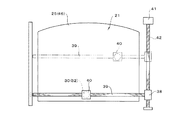
さらに、図8に示す実施例は、磁力手段を駆動手段により可変表示器21のほぼ全面を自由に移動し得るようにしたものである。この実施例では駆動手段として、第一モータ38により回転する横螺旋軸39に磁力手段としての永久磁石30を設けたナット40を螺合し、横螺旋軸39がさらに第二モータ41により回転する縦螺旋軸42に連結している。そして、横螺旋軸39が縦螺旋軸42の正逆回転により該縦螺旋軸42上を上下に移動し、横螺旋軸39の正逆回転により該横螺旋軸39上をナット40が左右に移動する。このため、永久磁石30は液晶表示パネル25の裏面に沿って表示部のほぼ全域を自由に移動することができる。ナット40は角ナットであり、永久磁石30を設けた前面が液晶表示パネル25の裏面に沿って摺動するため、ナット40は回動することなく、横螺旋軸39を左右方向に移動することができる。このように磁力手段を構成することで、前記実施例で示したように磁力手段として電磁石32を複数並列させることなく、電磁石32を複数並列させたのと同様に遊技球を自由に移動させることができるため、コストの低減化が図れ、さらに永久磁石30に吸着させた遊技球の細かな移動が可能となり、滑らかな図柄を描くことができる。また、この実施例においてもナット40に設けた永久磁石30を電磁石32とすることで、電磁石32を消励磁させて任意に遊技球を吸着させることができ、遊技客の興趣を高めることができる。なお、磁力手段は制御装置により動きを制御されるが、パチンコ遊技機の前面に操作レバーを設けて、遊技者が操作レバーを操作することで任意に磁力手段を移動させるようにしてもよい。具体的には、遊技者が任意で操作レバーを操作して、磁石に吸着させた遊技球を移動させることにより所定の図柄,数字を描いたり、所定の場所に遊技球を運んだりすることができ、遊技者の遊技意欲を高めることができる。また、遊技者に所定の図柄,数字を描かせたり、所定の場所に遊技球を運ばせたりする場合に、薄型表示パネルに「20秒以内に完成させよ」等の指令表示を行い、その指令が達成した際に「大当り」となるように、制御装置により制御することで、遊技客を遊技に熱中させることができる。このときのリーチ状態がはずれ設定の場合には、時間内に電磁石32を消磁させ吸着した遊技球を落下させるようにすればよい。なお、実施例において磁力手段を薄型表示パネルの裏面に沿って可動するようにしたが、磁力手段として周面の所定位置に磁石を設けたローラを回転自在に設けることにより、薄型表示パネルの前面に対して磁石が近接したときに磁力を及ぼしたり、離れたときに磁力が及ばないようにしたりすることができる。また、磁力手段を薄型表示パネルから離れるように前後方向にも可動し得るようにしてもよい。このようにすることで、磁力手段を永久磁石30からなるようにした際に、磁力調整が可能となり、永久磁石30を後方に移動させると薄型表示パネルの前面に対して及ぼす磁力が弱まることで、遊技球の吸着を任意で解除させることができる。   Further, the embodiment shown in FIG. 8 is configured such that the magnetic force means can be moved freely over almost the entire surface of the variable display 21 by the driving means. In this embodiment, as a driving means, a nut 40 provided with a permanent magnet 30 as a magnetic means is screwed to a horizontal spiral shaft 39 rotated by a first motor 38, and the horizontal spiral shaft 39 is further rotated by a second motor 41. It is connected to the vertical spiral shaft 42. Then, the horizontal spiral shaft 39 moves up and down on the vertical spiral shaft 42 by forward and reverse rotation of the vertical spiral shaft 42, and the nut 40 moves on the horizontal spiral shaft 39 by right and left rotation by the forward and reverse rotation of the horizontal spiral shaft 39. To do. For this reason, the permanent magnet 30 can freely move along substantially the entire area of the display unit along the back surface of the liquid crystal display panel 25. The nut 40 is a square nut, and the front surface provided with the permanent magnet 30 slides along the back surface of the liquid crystal display panel 25. Therefore, the nut 40 does not rotate and moves the horizontal spiral shaft 39 in the left-right direction. Can do. By configuring the magnetic force means in this way, the game balls can be moved freely as in the case where a plurality of electromagnets 32 are arranged in parallel without using a plurality of electromagnets 32 as a magnetic means as shown in the above embodiment. Therefore, the cost can be reduced, and the game ball attracted to the permanent magnet 30 can be moved finely, and a smooth design can be drawn. Also in this embodiment, by using the permanent magnet 30 provided on the nut 40 as the electromagnet 32, the electromagnet 32 can be de-energized to arbitrarily attract the game ball, thereby enhancing the interest of the player. . The movement of the magnetic force means is controlled by the control device, but an operation lever may be provided on the front surface of the pachinko gaming machine so that the player can arbitrarily move the magnetic force means by operating the operation lever. Specifically, a player may arbitrarily operate an operation lever to move a game ball attracted by a magnet to draw a predetermined pattern or number, or carry a game ball to a predetermined place. It is possible to increase the player's willingness to play. In addition, when a player draws a predetermined pattern or number, or carries a game ball to a predetermined place, a command display such as “Complete within 20 seconds” is displayed on the thin display panel. By controlling with a control device so that it becomes a “hit” when the command is achieved, the player can be engrossed in the game. If the reach state at this time is set to be off, the electromagnet 32 may be demagnetized within the time to drop the attracted game ball. In the embodiment, the magnetic force means is movable along the back surface of the thin display panel. However, as the magnetic force means, a roller provided with a magnet at a predetermined position on the peripheral surface is rotatably provided so that the front surface of the thin display panel can be rotated. For example, a magnetic force can be exerted when the magnet approaches, and a magnetic force can be prevented from exerting when the magnet is separated. Further, the magnetic force means may be movable in the front-rear direction so as to be separated from the thin display panel. Thus, when the magnetic force means is made of the permanent magnet 30, the magnetic force can be adjusted. When the permanent magnet 30 is moved backward, the magnetic force exerted on the front surface of the thin display panel is weakened. The adsorption of the game ball can be arbitrarily released.

また、磁力手段を特定のときにのみ作用させる場合には、磁力手段を電磁石32とするか、図9に示すように飾り部材17に開設された球導入口22に、電気的駆動源により球導入口22を開閉する板状の開閉部材43を配設して球導入口22からの入球を規制するようにすればよい。この実施例において、開閉部材43を可動させる電気的駆動源としてソレノイド44を設け、所定条件によりソレノイド44を励磁させて開閉部材43を可動して球導入口22を開放し、球導入口22から遊技球を流入させて液晶表示パネル25の前面に導くようにしている。なお、開閉部材43は一対の開閉翼片としてもよく、常態で開閉翼片を起立させ所定条件によりソレノイド等の電気的駆動源を駆動して開閉翼片を傾動させて遊技球を球導入口22から流入しやすくすればよい。また、この実施例のように磁力手段を特定のときにのみ作用させる場合において、例えば磁力手段として図9に示すように放射状のアーム34aの先端に永久磁石30を設けた可動体34を、モータ33により回転自在に設けると共に凹室18の側部に始動入賞口45を開設し、所定条件(例えば「大当り」図柄が次回の大当りが確定となる所謂各片図柄のとき)により前記ソレノイド44を励磁すると共にモータ33を駆動して可動体34を回転させ、球導入口22から導かれた遊技球を液晶表示パネル25を介して永久磁石30に吸着させて始動入賞口45に導くようにして、遊技の趣向を高めることができる。なお、初めて遊技するお客にも理解できるように、図9に示すように液晶表示パネル25に永久磁石30の場所を示す「矢印」と共に「ココに球を導け!」等の案内を表示するのが好ましく、遊技者は遊技内容を理解して遊技をすることができる。   Further, when the magnetic force means is applied only at a specific time, the magnetic force means is an electromagnet 32, or a sphere by an electric drive source is inserted into the sphere inlet 22 opened in the decorative member 17 as shown in FIG. A plate-like opening / closing member 43 that opens and closes the introduction port 22 may be provided to restrict entry from the ball introduction port 22. In this embodiment, a solenoid 44 is provided as an electric drive source for moving the opening / closing member 43, the solenoid 44 is excited according to a predetermined condition, the opening / closing member 43 is moved to open the ball introduction port 22, and A game ball is introduced and guided to the front surface of the liquid crystal display panel 25. The opening / closing member 43 may be a pair of opening / closing wing pieces, and the opening / closing wing pieces are erected in a normal state and an electric drive source such as a solenoid is driven under a predetermined condition to tilt the opening / closing wing piece to bring the game ball into the ball inlet. What is necessary is just to make it easy to flow in from 22. Further, in the case where the magnetic force means is applied only at a specific time as in this embodiment, for example, as shown in FIG. 9, the movable body 34 provided with the permanent magnet 30 at the tip of the radial arm 34a is used as the magnetic means. 33, and a start winning opening 45 is opened on the side of the concave chamber 18, and the solenoid 44 is operated according to a predetermined condition (for example, when each “big hit” symbol is a so-called single symbol in which the next big hit is determined). The magnet 33 is excited and the motor 33 is driven to rotate the movable body 34, so that the game ball guided from the ball introduction port 22 is attracted to the permanent magnet 30 through the liquid crystal display panel 25 and guided to the start winning port 45. , Can enhance the taste of the game. In addition, as shown in FIG. 9, a guidance such as “Give the ball to here!” Is displayed on the liquid crystal display panel 25 together with an “arrow” indicating the location of the permanent magnet 30, as shown in FIG. It is preferable that the player understands the game content and can play the game.

また、磁力手段を特定のときにのみ作用させる方法として、球導入口22を開閉させることなく、磁力手段を移動自在に設けて、磁力が薄型表示パネルの前面に及ぶ磁力モードと磁力が薄型表示パネルの前面に及ばない非磁力モードとに変換し得るようにすればよい。例えば図3に示したように薄型表示パネルの裏面全体に永久磁石30を設けた場合には、その磁力手段を駆動源により左右又は上下に移動自在に設け、駆動源の駆動により磁力手段を薄型表示パネルの裏面から後退するようにして、所定条件により磁力手段を可動させて、永久磁石30が薄型表示パネルの裏面に位置する磁力モードに切替えるようにすればよい。このとき、磁力手段の移動量を少なくするために、磁力手段を分割形成するのが好ましい。また、磁力モードと非磁力モードとの切替え方法として磁力手段をベルト状に形成し、ベルトを回転させることにより磁力モードと非磁力モードとに変換させるようにしてもよい。具体的には薄型表示パネルの裏面に近接して永久磁石30が位置する状態と、永久磁石30がベルトの回転により裏側に移動し薄型表示パネルから離間した状態とに変換される。   Further, as a method of causing the magnetic force means to act only at a specific time, the magnetic force means is provided movably without opening and closing the sphere inlet 22, and the magnetic force mode in which the magnetic force reaches the front surface of the thin display panel and the magnetic force is thinly displayed. What is necessary is just to enable conversion to a non-magnetic mode that does not reach the front surface of the panel. For example, as shown in FIG. 3, when the permanent magnet 30 is provided on the entire back surface of the thin display panel, the magnetic force means is provided so as to be movable left and right or up and down by the drive source, and the magnetic force means is thin by driving the drive source. The permanent magnet 30 may be switched to the magnetic force mode positioned on the back surface of the thin display panel by moving the magnetic force means according to a predetermined condition so as to move backward from the back surface of the display panel. At this time, in order to reduce the amount of movement of the magnetic means, it is preferable to form the magnetic means separately. Further, as a switching method between the magnetic mode and the non-magnetic mode, the magnetic force means may be formed in a belt shape, and converted into the magnetic mode and the non-magnetic mode by rotating the belt. Specifically, the state is converted into a state in which the permanent magnet 30 is located close to the back surface of the thin display panel and a state in which the permanent magnet 30 moves to the back side due to the rotation of the belt and is separated from the thin display panel.

これまで、薄型表示パネルを液晶表示パネル25として説明してきたが、薄型表示パネルをエレクトロルミネッセンス材料に電圧を印加させて発光させることにより表示態様を変化させる有機EL表示パネル46としてもよく、有機EL表示パネル46は液晶表示パネル25のようにバックライト26を必要としないので表示装置9をコンパクトにすることができる。また、液晶表示パネル25のようにバックライト26に規制されることがないため、図7乃至図9の実施例で示した磁力手段の駆動手段等を自由に設けることができる。このときも、有機EL表示パネル46の後面に位置する磁力手段が、該有機EL表示パネル46により遮蔽され遊技者から視認できないようにするのが好ましい。また、有機EL表示パネル46を介して該有機EL表示パネル46の後面が視認し得るようにした場合には、有機EL表示パネル46の後面に遊技球が流下し得るように遊技球の流下経路を設け、流下する遊技球が遊技者に視認できるようにするのがよく、遊技者は有機EL表示パネル46の前後を流下する遊技球に今までに味わったことのない興趣を感じることができる。このとき、有機EL表示パネル46の後面を流下する遊技球を磁力手段に吸着させる等して、有機EL表示パネル46の前面を流下する遊技球と関連づけて遊技をするようにしてもよい。   So far, the thin display panel has been described as the liquid crystal display panel 25. However, the thin display panel may be an organic EL display panel 46 that changes the display mode by applying a voltage to the electroluminescent material to emit light. Since the display panel 46 does not require the backlight 26 unlike the liquid crystal display panel 25, the display device 9 can be made compact. Further, since it is not restricted by the backlight 26 unlike the liquid crystal display panel 25, the driving means of the magnetic means shown in the embodiments of FIGS. 7 to 9 can be freely provided. Also at this time, it is preferable that the magnetic means located on the rear surface of the organic EL display panel 46 is shielded by the organic EL display panel 46 so that it cannot be seen by the player. Further, when the rear surface of the organic EL display panel 46 can be visually recognized through the organic EL display panel 46, the flow path of the game balls so that the game balls can flow down to the rear surface of the organic EL display panel 46. It is preferable that the player can visually recognize the game balls flowing down, and the player can feel the fun that has never been experienced before with the game balls flowing down the front and back of the organic EL display panel 46. . At this time, a game ball flowing down the rear surface of the organic EL display panel 46 may be attracted to a magnetic force means so that a game is played in association with the game ball flowing down the front surface of the organic EL display panel 46.

なお、本発明は、上記説明した実施例に限定されるものではなく、本発明の要旨を逸脱しない範囲で種々変更を付加してもよい。例えば前記薄型表示パネルは、支持枠19を介することなく、前面に遊技球が流下し得るように透明板扉枠3から所定間隔隔てて、薄型表示パネルの前面が遊技盤7面とほぼ同一面となるように設けるようにしてもよい。また、実施例では弾球遊技機としてパチンコ遊技機として説明したが、弾球遊技機として遊技球を賞媒体として用いるアレンジボール機,雀球遊技機に本発明を適用することができる。   The present invention is not limited to the above-described embodiments, and various modifications may be made without departing from the gist of the present invention. For example, the thin display panel is spaced from the transparent door frame 3 by a predetermined distance so that a game ball can flow down to the front without the support frame 19, and the front of the thin display panel is substantially flush with the surface of the game board 7. You may make it provide so that it may become. In the embodiments, the pachinko gaming machine has been described as the ball game machine, but the present invention can be applied to an arrangement ball machine and a sparrow ball game machine that use a game ball as an award medium as the ball ball game machine.

本発明の実施例を示すパチンコ遊技機の正面図である。1 is a front view of a pachinko gaming machine showing an embodiment of the present invention. 本発明に係る遊技機用表示装置の斜視図である。It is a perspective view of the display device for gaming machines according to the present invention. 遊技盤に取付けた表示装置の正面図である。It is a front view of the display apparatus attached to the game board. 図3の側面断面図である。FIG. 4 is a side sectional view of FIG. 3. バックライトの要部斜視図である。It is a principal part perspective view of a backlight. 他の実施例の表示装置の遊技態様を示す正面図である。It is a front view which shows the game aspect of the display apparatus of another Example. 磁力手段を可動自在に設けた実施例の正面図である。It is a front view of the Example which provided the magnetic means movably. 磁力手段を可動自在に設けた他の実施例の作用説明図である。It is operation | movement explanatory drawing of the other Example which provided the magnetic means movably. 導入口を開閉自在とした実施例を一部断面にして示す表示装置の正面図である。It is a front view of the display apparatus which shows the Example which made the introduction port freely openable and partially shows a cross section.

符号の説明Explanation of symbols

3 透明板扉枠
7 遊技盤
22 球導入口
25 液晶表示パネル(可変表示パネル)
30 永久磁石(磁力手段)
32 電磁石(磁力手段)
33 正逆モータ(電気的駆動源)
38 第一モータ(電気的駆動源)
41 第二モータ(電気的駆動源)
43 開閉部材
44 ソレノイド(電気的駆動源)
46 有機EL表示パネル(可変表示パネル)
3 Transparent plate door frame 7 Game board 22 Ball inlet 25 Liquid crystal display panel (variable display panel)
30 Permanent magnet (magnetic force means)
32 Electromagnet (Magnetic force means)
33 Forward / reverse motor (electric drive source)
38 First motor (electric drive source)
41 Second motor (electric drive source)
43 Opening / closing member 44 Solenoid (electric drive source)
46 Organic EL display panel (variable display panel)

Claims (4)

遊技盤に図柄等を可変表示する薄型表示パネルが設けられ、透明板扉枠を介して前記薄型表示パネルの表示を視認し得る弾球遊技機であって、
前記薄型表示パネルの前面を遊技球が流下し得るように該薄型表示パネルを前記透明板扉枠から所定間隔隔てて設け、前記薄型表示パネルの後面に前記遊技球の流下態様を変動させるべく該遊技球に対して磁力を及ぼす磁力手段を設けたことを特徴とする弾球遊技機。
A ball game machine in which a thin display panel for variably displaying symbols and the like is provided on the game board, and the display of the thin display panel can be visually recognized through a transparent plate door frame,
The thin display panel is provided at a predetermined interval from the transparent plate door frame so that a game ball can flow down the front surface of the thin display panel, and the flow down mode of the game ball is changed on the rear surface of the thin display panel. A bullet ball game machine comprising a magnetic means for exerting a magnetic force on a game ball.
前記磁力手段を前記薄型表示パネルの裏面側で可動させる電気的駆動源を設けたことを特徴とする請求項1記載の弾球遊技機。   2. The bullet ball game machine according to claim 1, further comprising an electric drive source for moving the magnetic force means on the back side of the thin display panel. 前記薄型表示パネルの上方に位置して該薄型表示パネルの前面に遊技球を導く球導入口を設けたことを特徴とする請求項1又は2記載の弾球遊技機。   The ball game machine according to claim 1 or 2, wherein a ball introduction port for guiding a game ball to the front surface of the thin display panel is provided above the thin display panel. 前記球導入口に電気的駆動源により該球導入口を閉鎖する開閉部材を設けたことを特徴とする請求項3記載の弾球遊技機。   4. The bullet ball game machine according to claim 3, wherein an opening / closing member for closing the ball introduction port by an electric drive source is provided at the ball introduction port.
JP2004120658A 2004-04-15 2004-04-15 Pachinko game machine Pending JP2005296519A (en)

Priority Applications (1)

Application Number Priority Date Filing Date Title
JP2004120658A JP2005296519A (en) 2004-04-15 2004-04-15 Pachinko game machine

Applications Claiming Priority (1)

Application Number Priority Date Filing Date Title
JP2004120658A JP2005296519A (en) 2004-04-15 2004-04-15 Pachinko game machine

Publications (1)

Publication Number Publication Date
JP2005296519A true JP2005296519A (en) 2005-10-27

Family

ID=35328761

Family Applications (1)

Application Number Title Priority Date Filing Date
JP2004120658A Pending JP2005296519A (en) 2004-04-15 2004-04-15 Pachinko game machine

Country Status (1)

Country Link
JP (1) JP2005296519A (en)

Cited By (10)

* Cited by examiner, † Cited by third party
Publication number Priority date Publication date Assignee Title
JP2007229383A (en) * 2006-03-03 2007-09-13 Olympia:Kk Movable accessory device of game machine
JP2007236621A (en) * 2006-03-08 2007-09-20 Sanyo Product Co Ltd Game machine
JP2007267923A (en) * 2006-03-31 2007-10-18 Samii Kk Pinball game machine
JP2008154722A (en) * 2006-12-22 2008-07-10 Heiwa Corp Game machine
JP2008154645A (en) * 2006-12-21 2008-07-10 Asama Seisakusho:Kk Amusement machine center case
JP2009195422A (en) * 2008-02-20 2009-09-03 Heiwa Corp Winning device for pachinko game machine
JP2010188055A (en) * 2009-02-20 2010-09-02 Sophia Co Ltd Game machine
JP2013198813A (en) * 2013-07-10 2013-10-03 Sanyo Product Co Ltd Game machine
JP2014097336A (en) * 2013-10-04 2014-05-29 Sanyo Product Co Ltd Game machine
JP2016032529A (en) * 2014-07-31 2016-03-10 日本ぱちんこ部品株式会社 Presentation device for game machine and game machine provided therewith

Citations (4)

* Cited by examiner, † Cited by third party
Publication number Priority date Publication date Assignee Title
JPH02136153A (en) * 1988-11-17 1990-05-24 Sankyo Kk Pin ball machine
JPH0681580U (en) * 1993-05-15 1994-11-22 治之 秋田 Amusement machine
JP2002017998A (en) * 2000-07-03 2002-01-22 Heiwa Corp Accessory device of game machine
JP2004000324A (en) * 2002-05-28 2004-01-08 Sophia Co Ltd Pachinko machine

Patent Citations (4)

* Cited by examiner, † Cited by third party
Publication number Priority date Publication date Assignee Title
JPH02136153A (en) * 1988-11-17 1990-05-24 Sankyo Kk Pin ball machine
JPH0681580U (en) * 1993-05-15 1994-11-22 治之 秋田 Amusement machine
JP2002017998A (en) * 2000-07-03 2002-01-22 Heiwa Corp Accessory device of game machine
JP2004000324A (en) * 2002-05-28 2004-01-08 Sophia Co Ltd Pachinko machine

Cited By (10)

* Cited by examiner, † Cited by third party
Publication number Priority date Publication date Assignee Title
JP2007229383A (en) * 2006-03-03 2007-09-13 Olympia:Kk Movable accessory device of game machine
JP2007236621A (en) * 2006-03-08 2007-09-20 Sanyo Product Co Ltd Game machine
JP2007267923A (en) * 2006-03-31 2007-10-18 Samii Kk Pinball game machine
JP2008154645A (en) * 2006-12-21 2008-07-10 Asama Seisakusho:Kk Amusement machine center case
JP2008154722A (en) * 2006-12-22 2008-07-10 Heiwa Corp Game machine
JP2009195422A (en) * 2008-02-20 2009-09-03 Heiwa Corp Winning device for pachinko game machine
JP2010188055A (en) * 2009-02-20 2010-09-02 Sophia Co Ltd Game machine
JP2013198813A (en) * 2013-07-10 2013-10-03 Sanyo Product Co Ltd Game machine
JP2014097336A (en) * 2013-10-04 2014-05-29 Sanyo Product Co Ltd Game machine
JP2016032529A (en) * 2014-07-31 2016-03-10 日本ぱちんこ部品株式会社 Presentation device for game machine and game machine provided therewith

Similar Documents

Publication Publication Date Title
JP2004255178A (en) Display device for game machine
JP2009100915A (en) Game board
JP2010051355A (en) Game table
JP2005296519A (en) Pachinko game machine
JP2003169919A (en) Game machine
JP2008017861A (en) Pachinko machine
JP2009066353A (en) Bullet ball machine
JP4205545B2 (en) Game machine
JP2003047706A (en) Pachinko machine
JP5516669B2 (en) Game machine
JP2004275303A (en) Central role object of game machine
JP2004113669A (en) Game machine
JP2009119283A (en) Game machine
JP2007252536A (en) Game machine
JP2009066352A (en) Bullet ball machine
JP2010022712A (en) Game table
JP3752612B2 (en) Pachinko machine gaming ball control device
JP4993108B2 (en) Game machine
JP5353912B2 (en) Game machine
JP2002210113A (en) Pinball game machine
JP4603338B2 (en) Game machine
JP2003164571A (en) Game machine
JP2004113775A (en) Game machine
JP2006288695A (en) Game machine
JP2005177083A (en) Variable display device for pinball game machine

Legal Events

Date Code Title Description
A621 Written request for application examination

Free format text: JAPANESE INTERMEDIATE CODE: A621

Effective date: 20070326

A977 Report on retrieval

Free format text: JAPANESE INTERMEDIATE CODE: A971007

Effective date: 20091126

A131 Notification of reasons for refusal

Free format text: JAPANESE INTERMEDIATE CODE: A131

Effective date: 20091201

A02 Decision of refusal

Free format text: JAPANESE INTERMEDIATE CODE: A02

Effective date: 20100406