JP2005293690A - Laminating method of disk substrate and sheet-shaped member - Google Patents
Laminating method of disk substrate and sheet-shaped member Download PDFInfo
- Publication number
- JP2005293690A JP2005293690A JP2004105410A JP2004105410A JP2005293690A JP 2005293690 A JP2005293690 A JP 2005293690A JP 2004105410 A JP2004105410 A JP 2004105410A JP 2004105410 A JP2004105410 A JP 2004105410A JP 2005293690 A JP2005293690 A JP 2005293690A
- Authority
- JP
- Japan
- Prior art keywords
- adhesive sheet
- tape
- pressure
- disk substrate
- sensitive adhesive
- Prior art date
- Legal status (The legal status is an assumption and is not a legal conclusion. Google has not performed a legal analysis and makes no representation as to the accuracy of the status listed.)
- Withdrawn
Links
- 239000000758 substrate Substances 0.000 title claims abstract description 86
- 238000000034 method Methods 0.000 title claims abstract description 53
- 238000010030 laminating Methods 0.000 title claims abstract description 10
- 239000000853 adhesive Substances 0.000 claims abstract description 117
- 230000001070 adhesive effect Effects 0.000 claims abstract description 117
- 238000004080 punching Methods 0.000 claims abstract description 18
- 239000004820 Pressure-sensitive adhesive Substances 0.000 claims description 37
- 238000003825 pressing Methods 0.000 claims description 17
- 238000012546 transfer Methods 0.000 claims description 17
- 238000012545 processing Methods 0.000 claims description 14
- 238000004519 manufacturing process Methods 0.000 abstract description 2
- 238000010586 diagram Methods 0.000 description 7
- 238000004804 winding Methods 0.000 description 7
- 239000010408 film Substances 0.000 description 6
- 238000003860 storage Methods 0.000 description 6
- 239000002390 adhesive tape Substances 0.000 description 5
- 230000005540 biological transmission Effects 0.000 description 4
- 238000004140 cleaning Methods 0.000 description 4
- 230000002093 peripheral effect Effects 0.000 description 4
- 230000003287 optical effect Effects 0.000 description 3
- 210000000078 claw Anatomy 0.000 description 2
- 230000015572 biosynthetic process Effects 0.000 description 1
- 238000005255 carburizing Methods 0.000 description 1
- 238000005229 chemical vapour deposition Methods 0.000 description 1
- 238000007796 conventional method Methods 0.000 description 1
- 230000002950 deficient Effects 0.000 description 1
- 235000012489 doughnuts Nutrition 0.000 description 1
- 230000008030 elimination Effects 0.000 description 1
- 238000003379 elimination reaction Methods 0.000 description 1
- 230000001678 irradiating effect Effects 0.000 description 1
- 238000003475 lamination Methods 0.000 description 1
- 238000012986 modification Methods 0.000 description 1
- 230000004048 modification Effects 0.000 description 1
- 238000005121 nitriding Methods 0.000 description 1
- 238000005240 physical vapour deposition Methods 0.000 description 1
- 230000001681 protective effect Effects 0.000 description 1
- 238000011160 research Methods 0.000 description 1
- 229920005989 resin Polymers 0.000 description 1
- 239000011347 resin Substances 0.000 description 1
- 239000004065 semiconductor Substances 0.000 description 1
- 238000000926 separation method Methods 0.000 description 1
- 238000004528 spin coating Methods 0.000 description 1
- 230000003068 static effect Effects 0.000 description 1
- 229920003002 synthetic resin Polymers 0.000 description 1
- 239000000057 synthetic resin Substances 0.000 description 1
- 239000010409 thin film Substances 0.000 description 1
- 230000007704 transition Effects 0.000 description 1
Images

Landscapes
- Adhesive Tapes (AREA)
- Adhesives Or Adhesive Processes (AREA)
- Manufacturing Optical Record Carriers (AREA)
Abstract
Description
本発明は、光ディスク関し、更に詳しくは、ディスク基板と粘着シートの貼り合わせ方法に関する。 The present invention relates to an optical disc, and more particularly to a method for bonding a disc substrate and an adhesive sheet.
従来、印加された記録面に反射膜を形成し、更にこの上に保護膜を形成したものが知られている。 Conventionally, a reflection film is formed on an applied recording surface, and a protective film is further formed thereon.
例えば、ディスク基板の反射膜上に光透過層を形成し、この光透過層側からレーザ光を照射し、記録面に情報を書き込み、その情報を読み込むタイプの光ディスク、いわゆるCD−R、CD−RW、DVD−R、及びDVD−RWといったものが出現している。
これらは、1枚のディスク基板又は2枚のディスク基板を貼り合わせて厚みが1.2mmの光ディスクを構成しているものである。
For example, a light transmissive layer is formed on a reflective film of a disk substrate, laser light is irradiated from the light transmissive layer side, information is written on a recording surface, and the information is read, so-called CD-R, CD- RW, DVD-R, and DVD-RW have appeared.
In these, an optical disc having a thickness of 1.2 mm is configured by bonding one disc substrate or two disc substrates together.
ところが、上述したような光透過層側からレーザ光を照射して記録及び再生を行うようにした光ディスクは、光透過層の厚さの変動等が情報の高密度化の妨げとなるため、極力、均一な厚さの光透過層を形成する必要があった。
しかし、例えばディスク基板上に紫外線硬化樹脂を塗布しスピンナー上で高速回転させる方法、いわゆるスピンコート法では、必ずしも均一な膜厚の光透過層を形成させることはできなかった。
However, in the optical disc in which recording and reproduction are performed by irradiating the laser beam from the light transmitting layer side as described above, the variation in the thickness of the light transmitting layer prevents the information from being densified. Therefore, it was necessary to form a light transmission layer having a uniform thickness.
However, for example, a method of applying a UV curable resin on a disk substrate and rotating it at a high speed on a spinner, that is, a so-called spin coating method, cannot always form a light-transmitting layer having a uniform film thickness.
例えば、ディスク基板の周辺部分の光透過層の厚みが、それより内側の部分に比べて厚くなる等の欠点がある。
このようなことから、ディスク基板に一定の膜厚の合成樹脂性のシート状部材を貼り付けることにより、結果的に均一な膜厚の光透過層を形成する方法が提案されている。
シート状部材を貼り付けて光透過層を形成するためには、テープ基体(キャリアという)に円形状のシート状部材が一定間隔で仮付着されたテープを使う必要がある。
このようなテープ基体(「キャリア」という)に円形状のシート状部材が一定間隔で仮付着された粘着シート付きテープを使ったものとして、例えば、特許文献1に開示されているものがある。
For example, there is a drawback that the thickness of the light transmission layer in the peripheral portion of the disk substrate is thicker than that in the inner portion.
For this reason, a method has been proposed in which a synthetic resin sheet-like member having a constant film thickness is attached to a disk substrate, and as a result, a light transmission layer having a uniform film thickness is formed.
In order to form a light transmission layer by attaching a sheet-like member, it is necessary to use a tape in which circular sheet-like members are temporarily attached to a tape substrate (referred to as a carrier) at regular intervals.
For example, Patent Document 1 discloses a tape with a pressure-sensitive adhesive sheet in which circular sheet-like members are temporarily attached to a tape substrate (referred to as “carrier”) at regular intervals.
図9は、粘着シートをディスク基板に貼り付ける方法であり、テープ基体101に粘着シート102と剥離シート103とが貼付された粘着シート付きテープ104を使っている。
参考までにその作動を説明すると、この粘着シート付きテープ104は、巻取ローラ106が回転駆動することにより供給ローラ105から繰り出されて巻き取られる。
FIG. 9 shows a method of adhering an adhesive sheet to a disk substrate, which uses an adhesive sheet-attached
The operation will be described for reference. The adhesive sheet-attached
供給ローラ105から粘着シート付きテープ104が送り出されると、先ず、粘着シート付きテープ104を保護する合紙107が取り除かれてリール108に巻き取られる。
そして、粘着シート付きテープ104は、一対のニップローラ109に送られる。
供給ローラ105の近傍には剥離装置110が設けられており、剥離装置110によって上側巻取ローラ111Aから下側巻取ローラ111Bに向けて剥離シート103を除去するための除去テープ112が送り出され、ニップローラ109に送られる。
When the adhesive sheet-attached
Then, the adhesive sheet-attached
A
ニップローラ109は、粘着シート付きテープ104と除去テープ112とを挟み込み、粘着シート付きテープ104の剥離シート103を除去テープ112に貼着させる。
そして、この除去テープ112を下側巻取ローラ111Bにより巻き取ることで、剥離シート103も除去テープ112と共に巻き取られ、粘着シート102が露出するようになる。
この粘着シート102が露出した粘着シート付きテープ104は、インデックステーブル113上に載置されたディスク基板Dとその上方に待機している貼合わせ装置114との間に送られる。
The
Then, by winding the
The adhesive sheet-attached
次いで、貼合わせ装置114の加熱状態にされた弾性体115が下降し、粘着シート102がディスク基板Dに加熱状態で押圧される。
その結果、粘着シート102がディスク基板Dに貼り付けられるのである。
その後、剥離ローラ116の移動によりテープ基体101から粘着シート102が剥離される。
そして、最後に巻取ローラ106によりテープ基体101が巻き取られる。
Next, the
As a result, the
Thereafter, the
Finally, the
しかしながら、上述したような円形の粘着シート102及び剥離シート103を備えた粘着シート付きテープ104を使った粘着シートの貼り付け方法では、粘着シート付きテープ104(通常、円筒状に巻かれて一個となっている)を、前もって多数、用意しておく必要がある。
しかし、粘着シート付きテープ104は、保管の際や輸送の途中で、外力が加わったりすると、粘着シートに窪みができたり、極端には傷ができたりする。
例えば窪みができると、後の貼り合わせ工程において、粘着シートがディスク基板に均一に貼り合わされない。
また傷ができた場合は、確実に欠陥品となる。
また、従来、巻き付けられて商品となっている粘着シート付きテープ104を使用する際は、わざわざ、巻き付けを解いてやらなければならず、無駄な操作が必要となる。
However, in the method for attaching the adhesive sheet using the
However, when an external force is applied to the
For example, if a dent is formed, the adhesive sheet is not uniformly bonded to the disk substrate in the subsequent bonding step.
Moreover, when a damage | wound is made, it becomes a defective article reliably.
In addition, when using the
本発明は、かかる背景をもとになされたもので、このような従来技術の問題点を解決するためになされたものである。
すなわち、本発明は、ディスク基板と粘着シートとを貼り合わせるに当たり、生産効率を向上させることができ、且つ品質的にも優れたディスク基板と粘着シートとの貼り合わせ方法を提供することを目的とする。
The present invention has been made based on such a background, and has been made to solve such problems of the prior art.
That is, the present invention has an object to provide a method for bonding a disk substrate and an adhesive sheet that can improve production efficiency and is excellent in quality when the disk substrate and the adhesive sheet are bonded together. To do.
かくして、本発明者は、このような課題背景に対して鋭意研究を重ねた結果、ドーナツ状の粘着シート及び剥離シートを有する粘着シート付きテープ104を作成する工程を貼り付け工程にインライン化することで、効率良い流れができ且つ窪みや傷が生じるのを防止できることを見出し、この知見に基づいて本発明を完成させたものである。
Thus, as a result of earnest research on the background of such problems, the inventor inlined the process of creating the
すなわち、本発明は、(1)、テープ基体と、該テープ基体に貼着された粘着シートと、該粘着シートに貼着された剥離シートとよりなる粘着シート付きテープに、打ち抜き加工を行って中心穴を有するドーナツ状の粘着シートを形成し、且つ粘着シートから剥離シートを引き剥がすテープ処理工程と、該テープ処理工程を経た後、剥離ローラによりテープ基体を粘着シートから剥離させて粘着シートのみを受け治具の上面に転移載置させる転移載置工程と、該転移工程を経た後、受け治具に載置された粘着シートより一定距離離れた上方位置にディスク基板を保持するディスク保持工程と、ディスク保持工程を経た後、受け治具の上面に載置された粘着シートの上にディスク基板を押し付ける貼り付け工程と、よりなるディスク基板と粘着シートの貼り合わせ方法に存する。 That is, the present invention includes (1) punching a tape with a pressure-sensitive adhesive sheet comprising a tape base, a pressure-sensitive adhesive sheet attached to the tape base, and a release sheet attached to the pressure-sensitive adhesive sheet. A tape processing step of forming a donut-shaped adhesive sheet having a center hole and peeling the release sheet from the adhesive sheet, and after passing through the tape processing step, the tape substrate is separated from the adhesive sheet by a release roller, and only the adhesive sheet A transfer mounting step of transferring and mounting the upper surface of the receiving jig, and a disk holding step of holding the disk substrate at an upper position separated by a certain distance from the adhesive sheet placed on the receiving jig after the transfer step And after the disc holding step, the disc substrate and the adhesive comprising the pasting step of pressing the disc substrate onto the adhesive sheet placed on the upper surface of the receiving jig, Resides in the bonding method of the over door.
すなわち、本発明は、(2)、テープ処理工程における打ち抜き処理は、2個の相対するローラを使い、テープ基体と粘着シートと剥離シートとに中心穴を形成するための第1内抜き穴を打ち抜き、粘着シートと剥離シートとに、それらの外周を形成するための第2内抜き穴を打ち抜く上記(1)記載のディスク基板と粘着シートの貼り合わせ方法に存する。 That is, according to the present invention, (2) the punching process in the tape processing step uses two opposing rollers, and a first inner hole for forming a center hole in the tape substrate, the adhesive sheet, and the release sheet. The present invention resides in the method for laminating a disc substrate and an adhesive sheet according to the above (1), in which a second inner hole for punching and punching the adhesive sheet and the release sheet to form the outer periphery thereof is punched out.
すなわち、本発明は、(3)、貼り合わせ工程において、粘着シートの上にディスク基板を押し付けて貼り合わせるのは、真空中にて行う上記(1)記載のディスク基板と粘着シートの貼り合わせ方法に存する。 That is, according to the present invention, (3) in the bonding step, the disk substrate is pressed onto the pressure-sensitive adhesive sheet and bonded together in a vacuum. Exist.
すなわち、本発明は、(4)、受け治具は、受け台と該受け台の上面と面一になるように下方へ移動可能にされたボス体とよりなるものである上記(1)記載のディスク基板と粘着シートの貼り合わせ方法に存する。 That is, in the present invention, (4), the receiving jig is composed of a receiving base and a boss body which is movable downward so as to be flush with the upper surface of the receiving base. The disk substrate and the adhesive sheet are bonded together.
すなわち、本発明は、(5)、貼り合わせ工程においては、ボス体と押圧体とでディスク基板の中心穴周辺を把持し、その状態で、押圧体を受け台に押し付けるものである上記(4)記載のディスク基板と粘着シートの貼り合わせ方法に存する。 That is, according to the present invention, (5) in the bonding step, the boss body and the pressing body grip the periphery of the center hole of the disk substrate, and in that state, the pressing body is pressed against the cradle (4) ) It exists in the bonding method of the disc substrate and adhesive sheet of description.
すなわち、本発明は、(6)、転移工程においては、ボス体を受け台の上面と面一になるように下方へ移動させた状態で行う上記(4)記載のディスク基板と粘着シートの貼り合わせ方法に存する。 That is, the present invention relates to (6), in the transfer step, the boss body is moved downward so as to be flush with the upper surface of the cradle. It exists in the combination method.
すなわち、本発明は、(7)、粘着シート付きテープは、帯状のテープ基体と、該テープ基体に貼着され且つテープ基体の幅より狭い又は同一幅の帯状の粘着シートと、該粘着シートに貼着され且つ粘着シートの幅よりも広い又は同一幅の帯状の剥離シートとよりなる上記(1)記載のディスク基板と粘着シートの貼り合わせ方法に存する。 That is, the present invention relates to (7) a tape with a pressure-sensitive adhesive sheet, a belt-like tape base, a belt-like pressure-sensitive adhesive sheet that is attached to the tape base and is narrower than or equal to the width of the tape base, and the pressure-sensitive adhesive sheet. The present invention resides in the method for laminating a disc substrate and a pressure-sensitive adhesive sheet according to the above (1), which comprises a strip-shaped release sheet that is adhered and wider than or equal to the width of the pressure-sensitive adhesive sheet.
なお、本発明の目的に添ったものであれば、上記の(1)から(7)を適宜組み合わせた構成も採用可能である。 In addition, as long as the objective of this invention is met, the structure which combined said (1) to (7) suitably is also employable.
本発明によれば、テープ基体と、該テープ基体に貼着された粘着シートと、該粘着シートに貼着された剥離シートとよりなる粘着シート付きテープに、打ち抜き加工を行って中心穴を有するドーナツ状の粘着シートを形成し、且つ粘着シートから剥離シートを引き剥がすテープ処理工程と、該テープ処理工程を経た後、剥離ローラによりテープ基体を粘着シートから剥離させて粘着シートのみを受け治具の上面に転移載置させる転移載置工程と、該転移工程を経た後、受け治具に載置された粘着シートより一定距離離れた上方位置にディスク基板を保持するディスク保持工程、ディスク保持工程を経た後、受け治具の上面に載置された粘着シートの上にディスク基板を押し付ける貼り付け工程と、よりなるため、貼り合わせの工程全体が、常に一連の流れの中で効率的に行われる。 According to the present invention, a tape with an adhesive sheet comprising a tape substrate, an adhesive sheet attached to the tape substrate, and a release sheet attached to the adhesive sheet is punched to have a center hole. A tape processing step of forming a donut-shaped adhesive sheet and peeling the release sheet from the adhesive sheet, and after passing through the tape processing step, the tape substrate is separated from the adhesive sheet by a release roller, and only the adhesive sheet is received. A transfer mounting step of transferring and mounting on the upper surface of the disk, a disk holding step of holding the disk substrate at an upper position separated from the adhesive sheet placed on the receiving jig by a certain distance after passing through the transfer step, a disk holding step And the pasting process in which the disk substrate is pressed onto the adhesive sheet placed on the upper surface of the receiving jig. It is efficiently carried out in a series of flows.
また、押付け工程を真空中にて行うことにより、気泡の含まない粘着シートの貼り合わせが可能となる。
また、受け治具が共通して使用されているために、方法を達成するための装置としてもシンプルとなる。
In addition, by performing the pressing step in a vacuum, it is possible to bond an adhesive sheet that does not contain bubbles.
Moreover, since the receiving jig is used in common, the apparatus for achieving the method is simple.
以下、本発明を実施するための最良の形態を図面に基づいて説明する。
〔テープ処理工程〕
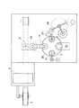
図1は、本発明の一実施形態に係るテープ処理装置を示す説明図である。
この一実施形態のテープ処理装置1では、粘着シート付きテープ2が供給ローラ3から送り出され粘着シート4が受け治具Gの上面に転移されるまでの間に、より具体的には、供給ローラ3とローラ5との間に、打ち抜き装置6が設けられている。
打ち抜き装置6は、円筒状のアンビルローラ7と、このアンビルローラ7と対向する円筒状のダイカットローラ8とを備えている。
アンビルローラ7とダイカットローラ8との間に粘着シート付きテープ2が挟み込まれて打ち抜きが行われる。
Hereinafter, the best mode for carrying out the present invention will be described with reference to the drawings.
[Tape processing process]
FIG. 1 is an explanatory diagram showing a tape processing apparatus according to an embodiment of the present invention.
In the tape processing apparatus 1 according to this embodiment, more specifically, the supply roller is supplied until the adhesive sheet-attached
The
The
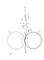
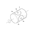
図2は、打ち抜き装置6におけるアンビルローラ7、ダイカットローラ8、及び粘着シート付きテープ2の関係を示す図であり、また図3はダイカットローラ8の斜視図を示している。
図に示すように、アンビルローラ7の外周面は平面であり、ダイカットローラ8の外周面には突起部が形成されている。
ダイカットローラ8の外周面には、テープ基体と粘着シート2と剥離シート9とに第1内抜き穴(中心穴に相当)2aを打ち抜くための輪環状の第1突起部8aと、粘着シートと剥離シートとに、それらの外周を形成するための第2内抜き穴2bを打ち抜くための輪環状の第2突起部8bとが形成されている
FIG. 2 is a view showing the relationship between the
As shown in the figure, the outer peripheral surface of the
On the outer peripheral surface of the
第1突起部8aは、テープ基体10までも貫くため、第2突起部8bよりも断面三角形状の歯の高さが高くなっている。
通常、第1突起部8aは、テープ基体10を貫くために、その先端がアンビルローラ7と接触し摩耗することから、その表面に窒化、浸炭、化学蒸着、物理蒸着等の表面硬化処理を施してある。
Since the
Usually, the
なお、粘着シート付きテープ2は、帯状のテープ基体10と、該テープ基体10に貼着され且つテープ基体10の幅より狭い帯状の粘着シート4と、該粘着シート4に貼着され且つ粘着シート4の幅よりも広い帯状の剥離シート9と、により構成されていることが好ましい。
打ち抜き装置6を通過した粘着シート付きテープ2には、第1打ち抜き穴2a(中心穴)や第2打ち抜き穴2bが形成され、粘着シート4はドーナツ状に処理される。
このドーナツ状にされた粘着シート4の外径L1は、例えばφ120とされ、中心穴は内径L2は、φ15とされる。
The adhesive sheet-attached
A first punched
The outer diameter L1 of the doughnut-shaped
打ち抜き装置6を通過した粘着シート付きテープ2は、図1に示すように、ローラ5を通過した後、ローラ11から供給される粘着テープ12と重ね合わされる。
粘着テープ12は一面のみに接着剤が付着しており、付着された方の面と、粘着シート付きテープ2の剥離シート9とが合わされて接着される。
この重ね合わされたテープ(粘着シート付きテープ2と粘着テープ12とが一体となったもの)は、クリーニング装置13によって、除電やクリーニングが行われる。
As shown in FIG. 1, the adhesive sheet-attached
Adhesive is attached to only one surface of the
The superposed tape (in which the adhesive sheet-attached
クリーニング装置13を経たテープ(粘着シート付きテープ2と粘着テープ12とが一体となったもの)は、テンションローラ等の複数のローラを通過した後、ドクターナイフ14を使って、剥離シート9(図2参照)が粘着テープ12と共にテープ基体10より引き剥がされローラ15に巻き取られる。
剥離シート9が引き剥がされた結果、粘着シート4の表面が露出する。
After passing through a plurality of rollers such as a tension roller, the tape that has passed through the cleaning device 13 (the
As a result of the
〔転移工程〕
剥離シート9が剥がされ粘着シート4が露出した状態の粘着シート付きテープ2は、転移装置16に送られる。
転移装置16には、粘着シートを転移させて載置するための受け治具Gが備わっている。
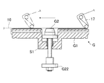
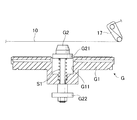
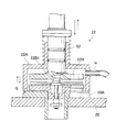
ここで図4は、ボス体が下方に移動した場合の受け治具Gを示す断面図であり、図5は、受け治具Gに粘着シートが転移載置された状態を示す断面図である。
受け治具Gは、円盤状の受け台G1と、この受け台G1の中央基部に配設されているボス体G2とを有している。
[Transition process]
The adhesive sheet-attached
The
4 is a cross-sectional view showing the receiving jig G when the boss body moves downward, and FIG. 5 is a cross-sectional view showing a state where the adhesive sheet is transferred and placed on the receiving jig G. .
The receiving jig G has a disk-shaped receiving base G1 and a boss body G2 disposed at the central base of the receiving base G1.
受け台G1の中央基部にはボス体G2を収納するための収納穴G11が形成されており、ボス体G2はこの収納穴G11に収納が可能である。
すなわち、ボス体G2は、受け台G1の上面と面一になるように下方へ弾圧的に移動して収納穴G11に収納される。
ボス体G2の下方への移動は、その下部G22を爪で引っ掛けることにより下げるがその手段は図示しない。
A storage hole G11 for storing the boss body G2 is formed in the central base of the cradle G1, and the boss body G2 can be stored in the storage hole G11.
That is, the boss body G2 is elastically moved downward so as to be flush with the upper surface of the cradle G1, and is stored in the storage hole G11.
The downward movement of the boss body G2 is lowered by hooking the lower part G22 with a claw, but the means is not shown.
収納された場合、ボス体G2はバネ体S1により上方に付勢状態にある。
ボス体G2は周辺に径大の鍔部G21を有しており、この上にディスク基板が載置可能となっている。
また受け台G1には図示しない吸着穴が設けられており、後述するように、粘着シート4が確りと吸引保持される。
さて転移装置16により粘着シートは受け治具Gに転移される。
すなわち、剥離ローラ17が水平移動してテープ基体10を粘着シート4から引き剥がすことにより(図4参照)、受け治具Gに粘着シート4が転移される(図5参照)。
When stored, the boss body G2 is biased upward by the spring body S1.
The boss body G2 has a flange part G21 having a large diameter at the periphery, and a disk substrate can be placed thereon.
Further, a suction hole (not shown) is provided in the cradle G1, and the
Now, the adhesive sheet is transferred to the receiving jig G by the
That is, the pressure-
剥離ローラ17が水平方向に移動する際は、ボス体G2が受け台G1の上面と面一になるまで下方へ弾圧的に移動して収納穴G11に収納状態となる。
ボス体G2の下方への移動が、その下部G22を爪で引っ掛けることにより行われることは既に述べた。
受け治具Gの受け台G1には図示しないが吸着穴が設けられており、粘着シート4からテープ基体10を引き剥がす際に、受け台G1で粘着シート4が確りと吸引保持される。
転移装置16で粘着シート4が剥がされたテープ、すなわちテープ基体10は、その後、複数のローラを通過した後、巻取ローラ18に巻き取られる。
受け治具Gは、粘着シート4が転移された後、図6に示すように、移動手段25によりスライドされて位置が移動し、その後、移載アーム19により回転テーブル20に載置される。
When the peeling
As described above, the downward movement of the boss body G2 is performed by hooking the lower portion G22 with a claw.
Although not shown, a suction hole is provided in the receiving base G1 of the receiving jig G, and when the
The tape from which the
After the
(ディスク保持工程)
回転テーブル20に載置された受け治具Gは、回転テーブルの間欠回転により、ディスク基板供給アーム21の位置に割り出される。
そしてディスク基板供給アーム21により、ディスク基板Dが供給される。
この場合、受け治具Gに転移された粘着シート4より上方に一定距離離れた位置にディスク基板Dを保持する。
具体的には、先述したように、ボス体G2は周辺に径大の鍔部G21を有しており、この上にディスク基板供給アーム21によってディスク基板Dが載置される。
(Disk holding process)
The receiving jig G placed on the rotary table 20 is indexed to the position of the disk
Then, the disk substrate D is supplied by the disk
In this case, the disk substrate D is held at a position away from the
Specifically, as described above, the boss body G2 has a flange portion G21 having a large diameter in the periphery, and the disk substrate D is placed thereon by the disk
〔貼り合わせ工程〕
次いで、この状態で回転テーブル20が間歇回転し、受け治具Gは真空貼り付け装置22に送られ、ディスク基板Dと粘着シート4との貼合わせが行われる。 ここでは、気泡の混入を防止するために真空中で貼合わせが行われる。
[Lamination process]
Next, in this state, the
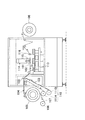
図7は、その真空貼り付け装置22を示す図である。
真空貼り付け装置22は、回転テーブル20に配置された受け治具G、真空チャンバ22A、押圧体22Bを備える。
真空チャンバ22Aの中には押圧体22Bが配設されており、該真空チャンバ22Aは押圧体22Bに対しバネ体S2を介して弾圧的に上下移動可能である。
FIG. 7 is a diagram showing the
The
A
そのため真空チャンバ22Aを下降させてその下端を回転テーブル20の上面に弾圧的に接地することができる。
なお、詳しくは、回転テーブル20には補助台20Aが嵌め込まれており、この基台20Aに真空チャンバ22Aの下端が圧接することとなる。
真空チャンバ22Aは吸引源に通じる吸引口Hから吸引することで、内部を限りなく負圧とすることができる。
受け治具Gは前述したような構造を備えており、回転テーブル20に(詳しくは、回転テーブルの補助台20Aに)嵌め込まれている。
Therefore, the
Specifically, the auxiliary table 20A is fitted in the rotary table 20, and the lower end of the
The
The receiving jig G has the structure as described above, and is fitted into the rotary table 20 (specifically, the auxiliary table 20A of the rotary table).
さて、次に貼り付け工程を述べる。
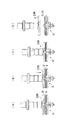
図8は、その真空貼り付け装置22を使って、粘着シート4にディスク基板を押し付ける操作順序を示す図である(尚、真空チャンバー22Aは便宜上、省略して示した)。
まず最初は、受け治具Gのボス体G2の鍔部G22にはディスク基板Dが保持されており、受け台G1の上面に転移され載置されている粘着シート4は、未だディスク基板に接触していない〔図8(A)参照〕
Now, the pasting process will be described.
FIG. 8 is a diagram showing an operation sequence for pressing the disk substrate against the pressure-
First, the disk substrate D is held on the flange G22 of the boss body G2 of the receiving jig G, and the
この状態で、上から受け治具Gを取り囲むように真空チャンバが降下し、回転テーブル20の上に接地する。
そして吸引口Hから吸引して真空チャンバ内を限りなく真空の状態にする。
その後、押圧体22Bを押し下げてボス体G2の鍔部G22と押圧体22Bとの間でディスク基板の中心穴周辺を把持し〔図8(B)参照〕、その状態のまま、押圧体22Bを受け台に接近させていく。
すると、ディスク基板Dは、ボス体G2と共に下降し、受け台G1に転移載置されている粘着シート4に押し付けられる〔図8(C)参照〕。
その結果、ディスク基板と粘着シート4とは貼り合わされるのである。
なお、この場合、ボス体G2の一部は、押圧体22Bの凹部22B1の中に挿入された状態となる。
その後、真空チャンバ及び押圧体22Bを引き上げて元の位置に戻すことで〔図8(D)参照〕、貼り付け工程は終了する。
In this state, the vacuum chamber descends so as to surround the receiving jig G from above and is grounded on the rotary table 20.
Then, suction is performed from the suction port H, and the inside of the vacuum chamber is brought into a vacuum state as much as possible.
Thereafter, the
Then, the disk substrate D is lowered together with the boss body G2 and pressed against the
As a result, the disk substrate and the
In this case, a part of the boss body G2 is inserted into the recess 22B1 of the
Thereafter, by pulling up the vacuum chamber and the
貼り付け工程が終了した後、また回転テーブル20が間歇回転して、受け治具Gは、次のディスク基板反転装置23に送られる。
そしてディスク基板反転装置23によりディスク基板Dの表裏面を反転させると、それが移載アーム24により受け取られて次の工程に送られる。
以上がディスク基板と粘着シートの貼り合わせ方法における全工程である。
After the pasting process is completed, the
Then, when the front and back surfaces of the disk substrate D are reversed by the disk
The above is all the steps in the method for bonding the disc substrate and the adhesive sheet.
上述した一実施形態の粘着シート貼付装置1では、テープ基体と、該テープ基体に貼着された粘着シートと、該粘着シートに貼着された剥離シートとよりなる粘着シート付きテープに、打ち抜き加工を行って中心穴を有するドーナツ状の粘着シートを形成し、且つ粘着シートから剥離シートを引き剥がすテープ処理工程を経ることにより、従来のように円形の粘着シート102及び剥離シート103を備えた粘着シート付きテープ104を多数用意しておく必要がなくなる。
In the pressure-sensitive adhesive sheet sticking apparatus 1 according to one embodiment described above, a punching process is performed on a tape with a pressure-sensitive adhesive sheet including a tape base, a pressure-sensitive adhesive sheet attached to the tape base, and a release sheet attached to the pressure-sensitive adhesive sheet. To form a doughnut-shaped pressure-sensitive adhesive sheet having a center hole, and through a tape processing step of peeling the release sheet from the pressure-sensitive adhesive sheet, a pressure-sensitive adhesive having a circular pressure-
そのため、粘着シート付きテープ104は、保管の際や輸送の途中で、外力が加わって、粘着シートに窪みができたり、傷ができたりすることがない。
結果的に、粘着シートがディスク基板に均一に貼り合わされ、品質的に優れたものとなる。
また粘着シート付きテープ104の在庫が切れることがなく、一連の作業の省力化が図られ生産性も向上する。
また貼り付け工程が真空中で行われるために、粘着シート4とディスク基板Dとの間に気泡が混入しない。
Therefore, the pressure-sensitive adhesive sheet-attached
As a result, the pressure-sensitive adhesive sheet is uniformly bonded to the disk substrate, and the quality is excellent.
Further, the inventory of the
Further, since the attaching process is performed in a vacuum, no bubbles are mixed between the
以上、本発明を説明してきたが、本発明は上述した一実施形態にのみ限定されるものではなく、その本質を逸脱しない範囲で、他の種々の変形が可能であることはいうまでもない。 Although the present invention has been described above, the present invention is not limited to the above-described embodiment, and various other modifications can be made without departing from the essence thereof. .
本発明は、ディスク基板と粘着シートの貼り合わせ方法に関するものであるが、その原理を逸脱しない限り、他の分野、例えば、半導体分野における薄膜の貼り合わせ方法にも適用可能であり、その応用分野は広い。 The present invention relates to a method for laminating a disk substrate and an adhesive sheet, but can be applied to a method for laminating thin films in other fields, for example, the semiconductor field, as long as the principle is not deviated. Is wide.
1 粘着シート貼付装置
2 粘着シート付きテープ
2a 第1内抜き穴(中心穴)
2b 第2内抜き穴
3 供給ローラ
4 粘着シート
5 ローラ
6 打ち抜き装置
7 アンビルローラ
8 ダイカットローラ
8a 第1突起部
8b 第2突起部
9 剥離シート
10 テープ基体
11 ローラ
12 粘着テープ
13 クリーニング装置
14 ドクターナイフ
15 ローラ
16 転移装置
17 剥離ローラ
18 巻取ローラ
19 移載アーム
20 回転テーブル
20A 補助台
21 ディスク基板供給アーム
22 真空貼付け装置
22A 真空チャンバ
22B 押圧体
22B1 凹部
23 ディスク基板反転装置
24 移載アーム
25 移動手段
101 テープ基体
102 粘着シート
103 剥離シート
104 粘着シート付きテープ
105 供給ローラ
106 巻取ローラ
107 合紙
108 リール
109 ニップローラ
110 剥離装置
111A 上側巻取ローラ
111B 下側巻取ローラ
112 除去テープ
113 インデックステーブル
114 貼合わせ装置
115 弾性体
116 剥離ローラ
D ディスク基板
G 受け治具
G1 受け台
G11 収納穴
G2 ボス体
G21 鍔部
G22 下部
S1,S2バネ体
DESCRIPTION OF SYMBOLS 1 Adhesive
2b 2nd inside hole 3
Claims (7)
該テープ処理工程を経た後、剥離ローラによりテープ基体を粘着シートから剥離させて粘着シートのみを受け治具の上面に転移載置させる転移載置工程と、
該転移工程を経た後、受け治具に載置された粘着シートより一定距離離れた上方位置にディスク基板を保持するディスク保持工程と、
ディスク保持工程を経た後、受け治具の上面に載置された粘着シートの上にディスク基板を押し付ける貼り付け工程と、
よりなることを特徴とするディスク基板と粘着シートの貼り合わせ方法。 A donut-shaped pressure-sensitive adhesive sheet having a center hole formed by punching a tape with a pressure-sensitive adhesive sheet comprising a tape base, a pressure-sensitive adhesive sheet attached to the tape base, and a release sheet attached to the pressure-sensitive adhesive sheet. A tape processing step of forming and peeling the release sheet from the adhesive sheet;
After passing through the tape processing step, a transfer mounting step in which the tape substrate is peeled off from the pressure sensitive adhesive sheet by a peeling roller, and only the pressure sensitive adhesive sheet is transferred and mounted on the upper surface of the jig,
After passing through the transfer step, a disc holding step for holding the disc substrate at an upper position that is a fixed distance away from the adhesive sheet placed on the receiving jig;
After passing through the disc holding step, an attaching step of pressing the disc substrate onto the adhesive sheet placed on the upper surface of the receiving jig,
A method for laminating a disc substrate and an adhesive sheet, comprising:
Priority Applications (1)
| Application Number | Priority Date | Filing Date | Title |
|---|---|---|---|
| JP2004105410A JP2005293690A (en) | 2004-03-31 | 2004-03-31 | Laminating method of disk substrate and sheet-shaped member |
Applications Claiming Priority (1)
| Application Number | Priority Date | Filing Date | Title |
|---|---|---|---|
| JP2004105410A JP2005293690A (en) | 2004-03-31 | 2004-03-31 | Laminating method of disk substrate and sheet-shaped member |
Publications (1)
| Publication Number | Publication Date |
|---|---|
| JP2005293690A true JP2005293690A (en) | 2005-10-20 |
Family
ID=35326464
Family Applications (1)
| Application Number | Title | Priority Date | Filing Date |
|---|---|---|---|
| JP2004105410A Withdrawn JP2005293690A (en) | 2004-03-31 | 2004-03-31 | Laminating method of disk substrate and sheet-shaped member |
Country Status (1)
| Country | Link |
|---|---|
| JP (1) | JP2005293690A (en) |
-
2004
- 2004-03-31 JP JP2004105410A patent/JP2005293690A/en not_active Withdrawn
Similar Documents
| Publication | Publication Date | Title |
|---|---|---|
| JP4215998B2 (en) | Semiconductor wafer processing method and semiconductor wafer transfer apparatus therefor | |
| JP6473359B2 (en) | Sheet peeling device | |
| JP3014979B2 (en) | Optical disc manufacturing method and apparatus used therefor | |
| TW201919969A (en) | Transport device, substrate processing system, transport method, and substrate processing method | |
| TW202145322A (en) | Sheet peeling method and sheet peeling device including the sheet-abutting step, the adhered object supporting step, and the sheet pulling step | |
| JP4519413B2 (en) | Tape sticking method and sticking device | |
| JP2015056613A (en) | Sheet sticking device and sticking method | |
| WO2017038470A1 (en) | Sheet detachment device and detachment method | |
| US20150255756A1 (en) | Apparatus and method for taking flexible display panel off, and method for manufacturing the same | |
| JP3200938U (en) | Sheet peeling device | |
| JP2005293690A (en) | Laminating method of disk substrate and sheet-shaped member | |
| JP2016178245A (en) | Sheet peeling apparatus, peeling method, and sheet transfer apparatus | |
| JP2005216426A (en) | Method for manufacturing optical disk | |
| JP2019075509A (en) | Adhesive sheet processing method and adhesive sheet processing apparatus | |
| JP2015082619A (en) | Sheet sticking device and sticking method | |
| JP6027399B2 (en) | Sheet sticking device and sheet sticking method | |
| JP6145326B2 (en) | Support apparatus and support method | |
| JP3924253B2 (en) | Manufacturing method of optical disk | |
| JP2015035452A (en) | Sheet sticking device and sheet sticking method | |
| JP2011151229A (en) | Supporting medium for adhesive sheet and support frame | |
| JP6097604B2 (en) | Sheet sticking device and sticking method | |
| JP6420172B2 (en) | Sheet feeding apparatus and feeding method | |
| JP2018129322A (en) | Sheet sticking device and sticking method | |
| JP2017107946A (en) | Sheet peeling device | |
| JP2015012138A (en) | Sheet sticking device and sticking method |
Legal Events
| Date | Code | Title | Description |
|---|---|---|---|
| A711 | Notification of change in applicant |
Effective date: 20060216 Free format text: JAPANESE INTERMEDIATE CODE: A712 |
|
| A621 | Written request for application examination |
Free format text: JAPANESE INTERMEDIATE CODE: A621 Effective date: 20070130 |
|
| A711 | Notification of change in applicant |
Free format text: JAPANESE INTERMEDIATE CODE: A711 Effective date: 20071214 |
|
| A521 | Written amendment |
Effective date: 20080218 Free format text: JAPANESE INTERMEDIATE CODE: A523 |
|
| A521 | Written amendment |
Effective date: 20080416 Free format text: JAPANESE INTERMEDIATE CODE: A523 |
|
| A521 | Written amendment |
Effective date: 20080428 Free format text: JAPANESE INTERMEDIATE CODE: A523 |
|
| A711 | Notification of change in applicant |
Free format text: JAPANESE INTERMEDIATE CODE: A711 Effective date: 20080428 |
|
| A761 | Written withdrawal of application |
Free format text: JAPANESE INTERMEDIATE CODE: A761 Effective date: 20080428 |