JP2005291553A - Multi-type air conditioner - Google Patents
Multi-type air conditioner Download PDFInfo
- Publication number
- JP2005291553A JP2005291553A JP2004103873A JP2004103873A JP2005291553A JP 2005291553 A JP2005291553 A JP 2005291553A JP 2004103873 A JP2004103873 A JP 2004103873A JP 2004103873 A JP2004103873 A JP 2004103873A JP 2005291553 A JP2005291553 A JP 2005291553A
- Authority
- JP
- Japan
- Prior art keywords
- indoor unit
- temperature
- indoor
- electronic expansion
- heat exchanger
- Prior art date
- Legal status (The legal status is an assumption and is not a legal conclusion. Google has not performed a legal analysis and makes no representation as to the accuracy of the status listed.)
- Pending
Links
Images
Classifications
-
- F—MECHANICAL ENGINEERING; LIGHTING; HEATING; WEAPONS; BLASTING
- F25—REFRIGERATION OR COOLING; COMBINED HEATING AND REFRIGERATION SYSTEMS; HEAT PUMP SYSTEMS; MANUFACTURE OR STORAGE OF ICE; LIQUEFACTION SOLIDIFICATION OF GASES
- F25B—REFRIGERATION MACHINES, PLANTS OR SYSTEMS; COMBINED HEATING AND REFRIGERATION SYSTEMS; HEAT PUMP SYSTEMS
- F25B49/00—Arrangement or mounting of control or safety devices
- F25B49/02—Arrangement or mounting of control or safety devices for compression type machines, plants or systems
-
- F—MECHANICAL ENGINEERING; LIGHTING; HEATING; WEAPONS; BLASTING
- F25—REFRIGERATION OR COOLING; COMBINED HEATING AND REFRIGERATION SYSTEMS; HEAT PUMP SYSTEMS; MANUFACTURE OR STORAGE OF ICE; LIQUEFACTION SOLIDIFICATION OF GASES
- F25B—REFRIGERATION MACHINES, PLANTS OR SYSTEMS; COMBINED HEATING AND REFRIGERATION SYSTEMS; HEAT PUMP SYSTEMS
- F25B2600/00—Control issues
- F25B2600/21—Refrigerant outlet evaporator temperature
Landscapes
- Engineering & Computer Science (AREA)
- Physics & Mathematics (AREA)
- Mechanical Engineering (AREA)
- Thermal Sciences (AREA)
- General Engineering & Computer Science (AREA)
- Air Conditioning Control Device (AREA)
Abstract
【課題】 異なる運転制御が可能な二台の室内機ユニットを有するマルチ型空気調和装置において、空調負荷に差がある場合であっても、それぞれの空調負荷に応じた適正な冷媒分配を可能にすること。
【解決手段】 独自の電子膨張弁14A,14Bを備えている2台の室内機ユニット20A,20Bを具備してなるマルチ型空気調和装置において、両室内機ユニットの室内熱交換器21A,21Bが、それぞれ二相流部の温度を検出する二相流部温度センサ23A,23Bと、気相部温度センサ24A,24Bとを備え、冷房運転時に二相流部温度センサ23A,23B及び気相部温度センサ24A,24Bで検出した温度差から各室内熱交換器21A,21B毎に出口過熱度を算出し、各室制御部からの圧縮機指令回転数および該出口過熱度に基づいて室内機ユニット毎に電子膨張弁14A,14Bの開度を個別に補正する過熱度制御モードを設けた。
【選択図】図1PROBLEM TO BE SOLVED: To provide an appropriate refrigerant distribution according to each air conditioning load in a multi-type air conditioner having two indoor unit units capable of different operation control even when there is a difference in air conditioning load. To do.
SOLUTION: In a multi-type air conditioner including two indoor unit units 20A and 20B having original electronic expansion valves 14A and 14B, indoor heat exchangers 21A and 21B of both indoor unit units are provided. The two-phase flow part temperature sensors 23A and 23B for detecting the temperature of the two-phase flow part, and the gas phase part temperature sensors 24A and 24B, respectively, and the two-phase flow part temperature sensors 23A and 23B and the gas phase part during the cooling operation. The outlet superheat degree is calculated for each of the indoor heat exchangers 21A and 21B from the temperature difference detected by the temperature sensors 24A and 24B, and the indoor unit unit is based on the compressor command rotational speed and the outlet superheat degree from each room controller. A superheat degree control mode for individually correcting the opening degree of the electronic expansion valves 14A and 14B is provided for each time.
[Selection] Figure 1
Description
本発明は、空調運転(冷房運転、暖房運転及び除湿運転)により空調空気を噴出する2台の室内機ユニットを備え、各室内機ユニット毎に異なる運転制御が可能なマルチ型空気調和装置に関する。 The present invention relates to a multi-type air conditioner that includes two indoor unit units that eject air-conditioned air by air-conditioning operation (cooling operation, heating operation, and dehumidifying operation), and can perform different operation control for each indoor unit.
室内の冷暖房や除湿(以下、総称して「空調」と呼ぶ)を行う空気調和装置は、室内機ユニットと室外機ユニットとの間を冷媒配管及び電気配線で接続した構成とされる。このような空気調和装置は、圧縮機、室外熱交換器、絞り機構、室内熱交換器及び四方弁を主な構成要素として冷媒の循環回路を形成するヒートポンプを用いており、圧縮機から送出される冷媒の循環方向を四方弁の操作によって切り換えることで、所望の空調運転を行っている。
このような空気調和装置には、一式の室外機ユニットに対し、室内機ユニットが一台接続された構成のシングル型と、それぞれ独自の運転制御を可能にした室内機ユニットが複数接続された構成のマルチ型とがある。
An air conditioner that performs indoor air conditioning and dehumidification (hereinafter collectively referred to as “air conditioning”) has a configuration in which an indoor unit and an outdoor unit are connected by a refrigerant pipe and an electrical wiring. Such an air conditioner uses a heat pump that forms a refrigerant circulation circuit with a compressor, an outdoor heat exchanger, a throttle mechanism, an indoor heat exchanger, and a four-way valve as main components, and is sent from the compressor. The desired air conditioning operation is performed by switching the circulation direction of the refrigerant by operating the four-way valve.
In such an air conditioner, a single type of configuration in which one indoor unit is connected to a set of outdoor unit and a configuration in which a plurality of indoor unit units each enabling independent operation control are connected There are multiple types.
上述した空気調和装置においては、圧縮機の吸入部及び吐出部での過熱度を評価して運転制御を行っているが、異なる運転制御が可能な複数台の室内機ユニット毎に過熱度を評価する運転制御は行われていない。
また、従来のマルチ型空気調和装置においては、バイパス回路を設けることなく低能力の室内熱交換器が接続された際の高圧側冷媒圧力の上昇を防止するため、室外熱交換器出口温度と低圧飽和温度とに基づいて、暖房運転時に過熱度制御を実施することが提案されている。(たとえば、特許文献1参照)
Further, in the conventional multi-type air conditioner, the outdoor heat exchanger outlet temperature and the low pressure are prevented in order to prevent an increase in the high-pressure side refrigerant pressure when a low-capacity indoor heat exchanger is connected without providing a bypass circuit. Based on the saturation temperature, it has been proposed to carry out superheat control during heating operation. (For example, see Patent Document 1)
ところで、異なる運転制御が可能な2台の室内機ユニットを備えているマルチ型空気調和装置において、圧縮機の吸入部及び吐出部での過熱度を評価して運転制御を行うという従来技術により冷房運転を実施すれば、両ユニットの運転負荷が大きく異なるような運転状況では、単純に各室内機の要求に従い冷媒循環量を按分しているだけでは次のような問題が生じてくる。
すなわち、空調負荷の高い室内機ユニット側では、室内熱交換器を通過する風量に対し冷媒循環量が多く分配されているため、室内熱交換器内の過熱域は小さくなり室内熱交換機のフィンは空気中の湿分が結露して十分に濡れている。一方、空調負荷の低い室内機ユニット側では、室内熱交換器を通過する風量に対し冷媒循環量の分配が少ないため、室内熱交換器内の過熱域は大きくなり結果として冷却する空気中の湿分が凝縮することなく通過するので、室内熱交換器のフィンは乾いたものとなる。
By the way, in a multi-type air conditioner equipped with two indoor unit units capable of different operation control, cooling is performed by a conventional technique in which operation control is performed by evaluating the degree of superheat at the suction and discharge portions of the compressor. When the operation is performed, in the operation situation in which the operation loads of both units are greatly different, the following problem arises simply by distributing the refrigerant circulation amount according to the demand of each indoor unit.
That is, on the indoor unit unit side where the air conditioning load is high, the amount of refrigerant circulation is distributed more than the amount of air passing through the indoor heat exchanger, so the overheat area in the indoor heat exchanger is reduced and the fins of the indoor heat exchanger are Moisture in the air has condensed and is sufficiently wet. On the other hand, on the indoor unit unit side where the air conditioning load is low, the distribution of refrigerant circulation is small with respect to the amount of air passing through the indoor heat exchanger, so the overheating area in the indoor heat exchanger becomes large and consequently the humidity in the air to be cooled is reduced. Since the minute passes without condensing, the fins of the indoor heat exchanger are dry.
しかし、圧縮機の吸入部では2台の空調運転に適正な過熱度となっているため、冷房負荷に大きな差があるにもかかわらず、そのまま冷房運転が継続されることとなる。このような状態で冷房運転が継続されると、分配されて循環する冷媒量に大きな差が生じることとなるため、二つの室内熱交換器を比較すると過熱度に大きな差が生じてしまう。このため、高温多湿の室内空気が十分な冷却能力のない乾いた室内熱交換器を通過する場合には除湿されない空調空気となって流出するため、室内熱交換器から湿分を含んだままの空調空気が予め冷えているランナ通路に流入することにより、ランナ通路内で冷やされて結露することが懸念される。このようなランナ結露が発生すると、室内機ユニットの吹出口から水滴が滴下したり、あるいは、室内機ユニットから吹き出す空調空気と共に水分が飛散するという不具合を生じて好ましくない。 However, since the degree of superheat is appropriate for the air conditioning operation of the two units at the suction portion of the compressor, the cooling operation is continued as it is even though there is a large difference in the cooling load. If the cooling operation is continued in such a state, a large difference occurs in the amount of refrigerant that is distributed and circulated. Therefore, when the two indoor heat exchangers are compared, a large difference occurs in the degree of superheat. For this reason, when hot and humid room air passes through a dry indoor heat exchanger that does not have sufficient cooling capacity, it flows out as conditioned air that is not dehumidified, so moisture remains contained from the indoor heat exchanger. When the conditioned air flows into the runner passage that has been cooled in advance, there is a concern that the air is cooled in the runner passage and condensation occurs. If such runner condensation occurs, water droplets may drip from the outlet of the indoor unit, or moisture may scatter with the conditioned air blown from the indoor unit.
このように、冷房負荷が異なる2台の室内機ユニットを冷房運転する場合、圧縮機の吸入部及び吐出部での過熱度を評価して運転制御を行うだけでは、室内熱交換器毎に空調負荷に見合った適正な冷媒量分配が行われているか否かを判断できないため、低負荷側でのランナ結露発生が問題となって対策が望まれている。
本発明は、上記の事情に鑑みてなされたものであり、異なる運転制御が可能な二台の室内機ユニットを有するマルチ型空気調和装置において、その空調負荷に差がある場合であっても、それぞれの空調負荷に応じた適正な冷媒分配を可能とする運転制御を提供することにある。
In this way, when two indoor unit units with different cooling loads are in cooling operation, air conditioning is performed for each indoor heat exchanger simply by evaluating the degree of superheat in the suction and discharge sections of the compressor and performing operation control. Since it is not possible to determine whether or not the proper refrigerant amount distribution corresponding to the load is being performed, the occurrence of runner condensation on the low load side becomes a problem, and a countermeasure is desired.
The present invention has been made in view of the above circumstances, and in a multi-type air conditioner having two indoor unit units capable of different operation control, even when there is a difference in the air conditioning load, An object of the present invention is to provide operation control that enables appropriate refrigerant distribution according to each air conditioning load.
本発明は、上記の課題を解決するため、下記の手段を採用した。
本発明に係るマルチ型空気調和機は、室外機ユニットと、該室内機ユニットに接続されそれぞれが独自の電子膨張弁を備えている2台の室内機ユニットとを具備してなるマルチ型空気調和装置において、前記室内機ユニットの室内熱交換器が、それぞれ二相流部の温度を検出する第1の温度検出手段と、気相側の温度を検出する第2の温度検出手段とを備え、冷房運転時に前記第1及び第2の温度検出手段で検出した温度差から各室内熱交換器毎に出口過熱度を算出し、該出口過熱度に基づいて前記室内機ユニット毎に前記電子膨張弁の開度を個別に補正する過熱度制御モードを備えていることを特徴とするものである。
In order to solve the above problems, the present invention employs the following means.
A multi-type air conditioner according to the present invention includes an outdoor unit and two indoor unit units connected to the indoor unit and each having a unique electronic expansion valve. In the apparatus, each of the indoor heat exchangers of the indoor unit includes first temperature detecting means for detecting the temperature of the two-phase flow section, and second temperature detecting means for detecting the temperature on the gas phase side, An outlet superheat degree is calculated for each indoor heat exchanger from the temperature difference detected by the first and second temperature detecting means during the cooling operation, and the electronic expansion valve is set for each indoor unit based on the outlet superheat degree. It is characterized by having a superheat degree control mode for individually correcting the opening degree.
このようなマルチ型空気調和装置によれば、室内機ユニットの室内熱交換器が、それぞれ二相流部の温度を検出する第1の温度検出手段と、気相側の温度を検出する第2の温度検出手段とを備え、冷房運転時に前記第1及び第2の温度検出手段で検出した温度差から各室内熱交換器毎に出口過熱度を算出し、該出口過熱度に基づいて前記室内機ユニット毎に前記電子膨張弁の開度を個別に補正する過熱度制御モードを備えているので、室内機ユニット毎に電子膨張弁の開度を個別に制御して出口過熱度のフィードバック制御を行うことができるようになり、空調負荷に大きな差がある場合であっても、各室内ユニット毎の過熱度評価を行ってそれぞれの電子膨張弁を開度調整するので、適正な冷媒分配が可能となる。 According to such a multi-type air conditioner, the indoor heat exchanger of the indoor unit unit includes the first temperature detecting means for detecting the temperature of the two-phase flow section and the second temperature for detecting the temperature on the gas phase side. Temperature detection means for calculating the outlet superheat degree for each indoor heat exchanger from the temperature difference detected by the first and second temperature detection means during cooling operation, and based on the outlet superheat degree, Since it has a superheat degree control mode that individually corrects the opening degree of the electronic expansion valve for each unit, the opening degree of the electronic expansion valve is individually controlled for each indoor unit and feedback control of the outlet superheat degree is performed. Even if there is a large difference in air conditioning load, the degree of superheat for each indoor unit is evaluated and the opening of each electronic expansion valve is adjusted, so that appropriate refrigerant distribution is possible It becomes.
上述した本発明のマルチ型空気調和機によれば、室内熱交換器のそれぞれに設けた二相流部の温度を検出する第1の温度検出手段と気相側の温度を検出する第2の温度検出手段とにより検出した温度差から各室内熱交換器毎に出口過熱度を算出し、該出口過熱度に基づいて前記室内機ユニット毎に前記電子膨張弁の開度を個別に補正する過熱度制御モードを備えているので、室内機ユニット毎に電子膨張弁の開度を個別に制御して出口過熱度のフィードバック制御を行い、空調負荷に大きな差がある場合であっても、各室内ユニット毎の過熱度評価を行ってそれぞれの電子膨張弁を開度調整し、各室内機ユニットの空調負荷に見合った適正な冷媒分配が可能となる。すなわち、空調負荷が異なる2台の室内機ユニットに見合った能力制御が可能となるので、低負荷側の室内機ユニットにおいて、冷媒供給量の不足により室内熱交換器が乾くことに起因して発生するランナー結露を防止または抑制することができる。 According to the above-described multi-type air conditioner of the present invention, the first temperature detecting means for detecting the temperature of the two-phase flow section provided in each of the indoor heat exchangers and the second temperature for detecting the temperature on the gas phase side. Overheating that calculates the outlet superheat degree for each indoor heat exchanger from the temperature difference detected by the temperature detecting means, and individually corrects the opening degree of the electronic expansion valve for each indoor unit based on the outlet superheat degree Degree control mode, the opening degree of the electronic expansion valve is individually controlled for each indoor unit to perform feedback control of the outlet superheat degree, even if there is a large difference in air conditioning load, The degree of superheat for each unit is evaluated and the opening of each electronic expansion valve is adjusted, so that appropriate refrigerant distribution corresponding to the air conditioning load of each indoor unit can be performed. In other words, the capacity control suitable for two indoor unit units with different air-conditioning loads is possible, and this occurs because the indoor heat exchanger dries out due to a shortage of refrigerant supply in the low-load indoor unit. Runner condensation can be prevented or suppressed.
以下、本発明に係るマルチ型空気調和装置の一実施形態について、図面を参照して説明する。
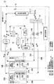
図1は、マルチ型空気調和装置の全体構成例を示す説明図である。このマルチ型空気調和装置は、室外機ユニット10と、同室外機ユニット10に接続された2台の室内機ユニット20(図示の例では、室内機ユニット20A,20B)とを具備して構成される。これら室内機ユニット10及び室外機ユニット20は、冷媒を流す冷媒配管30や図示しない電気配線等により接続されている。
Hereinafter, an embodiment of a multi-type air conditioner according to the present invention will be described with reference to the drawings.
FIG. 1 is an explanatory diagram illustrating an example of the overall configuration of a multi-type air conditioner. The multi-type air conditioner includes an
室外機ユニット10は、冷媒を圧縮して送出する圧縮機11と、冷媒の循環方向を切り換える四方弁12と、冷媒と外気との間で熱交換を行う室外熱交換器13と、絞り機構として機能する電子膨張弁14とを主な構成要素とし、さらに、消音の目的で圧縮機11の吐出側配管に配設されたマフラ15と、同じく消音の目的で圧縮機11の吸入管配管に配設された吸入マフラ16と、各種の運転制御を行う室外制御部17とを具備して構成される。なお、この室内機ユニット10には、この他にも図示省略の室外ファン、レシーバ、サービスバルブ及びストレーナ等の機器類や温度センサ等のセンサ類が設けられている。
The
室内機ユニット20のケーシング内には、室内熱交換器21や室内制御部22などの他にも図示しない室内ファン等の機器を収納した構成とされる。また、室内熱交換器21には、二相流部の温度を検出する二相流部温度センサ(第1の温度検出手段)23と、気相側の温度を検出する気相部温度センサ(第2の温度検出手段)24と、室内吸込空気の温度を検出する吸込温度センサ25とが設けられており、これらの温度センサで検出した温度データは室内制御部22に入力される。ここで、二相流部温度センサ23は、室内熱交換器21のパス中間部に取り付けた温度センサであり、二相流部における圧力飽和温度を検出している。また、気相部温度センサ24は、冷房運転時において室内熱交換器21の出口側(気相側)配管に取り付けた温度センサであり、気相冷媒の温度を検出している。
なお、図中の各符号に付記されたA,Bは、2つの室内機ユニットを区別して説明する場合にのみ使用するものとする。
The casing of the indoor unit 20 is configured to house devices such as an indoor fan (not shown) in addition to the indoor heat exchanger 21 and the indoor control unit 22. The indoor heat exchanger 21 includes a two-phase flow part temperature sensor (first temperature detection means) 23 for detecting the temperature of the two-phase flow part, and a gas phase part temperature sensor (first temperature detection means) for detecting the temperature on the gas phase side. (Second temperature detecting means) 24 and an intake temperature sensor 25 for detecting the temperature of the indoor intake air are provided, and temperature data detected by these temperature sensors is input to the indoor control unit 22. Here, the two-phase flow part temperature sensor 23 is a temperature sensor attached to the intermediate part of the path of the indoor heat exchanger 21, and detects the pressure saturation temperature in the two-phase flow part. The gas phase temperature sensor 24 is a temperature sensor attached to the outlet side (gas phase side) piping of the indoor heat exchanger 21 during the cooling operation, and detects the temperature of the gas phase refrigerant.
In addition, A and B attached to each code | symbol in a figure shall be used only when distinguishing and explaining two indoor unit units.
この室内機ユニット20は、室内ファンで吸引した室内の空気を室内熱交換器21に導いて通過させ、上述した室外機ユニット10から供給される冷媒との間で熱交換した空調空気を室内に吹き出すように構成されている。また、2台の室内機ユニット20A,20Bは、それぞれ異なる空調対象の部屋に設置され、各部屋の状況に応じて異なる運転制御が可能に構成されている。なお、ここでの異なる運転制御とは、冷房運転または暖房運転のいずれか一方を選択し、部屋毎に異なる空調負荷に対応した運転制御を行うこと意味しており、二つの室内機ユニット20A,20Bが暖房運転及び冷房運転のように異なる空調運転を同時に行うものではない。
The indoor unit 20 guides indoor air sucked by an indoor fan to the indoor heat exchanger 21 and passes it through the room, and the conditioned air heat-exchanged with the refrigerant supplied from the
2台の室内機ユニット20A,20Bは、それぞれ室外機ユニット10内のパイプコネクタ31,ヘッダー32で分岐した冷媒配管30A,30Bに接続されている。また、室外機ユニット10内の各冷媒配管30A,3Bには、それぞれ独立して動作する電子膨張弁14A,14Bが、室外熱交換器13と室内ユニット20A,20Bとの間に配設されている。
なお、上述した室内機ユニット10には、圧縮機11の吸入管センサ11a及び吐出管センサ11bと、室外熱交換器13の液相側に設けられた室外熱交センサ13aと、外気温を検出する外温センサ18とを具備し、それぞれの検出値が室外制御部17に入力されるようになっている。
The two
In the
以下では、上述した構成のマルチ型空気調和装置の作用について、冷房運転時及び暖房運転時のそれぞれの場合に分けて説明する。
最初に、冷房運転時の空調作用について、図中に矢印で示した冷媒の流れとともに説明する。なお、冷房運転及び暖房運転は、四方弁12の操作により変化する冷媒の流れ方向に応じて選択切換えされる。
Below, the effect | action of the multi type air conditioning apparatus of the structure mentioned above is divided and demonstrated in each case at the time of air_conditionaing | cooling operation and heating operation.
First, the air conditioning operation during the cooling operation will be described together with the refrigerant flow indicated by arrows in the drawing. In addition, the cooling operation and the heating operation are selectively switched according to the flow direction of the refrigerant that is changed by the operation of the four-
さて、圧縮機11の圧縮で高温高圧の気体とされた冷媒は、マフラ15及び四方弁12を通過して室外熱交換器13に送られ、室外の空気(以下、「室外気」と呼ぶ)と熱交換する。この熱交換により、高温高圧の気体冷媒が室外気に熱を与えて凝縮液化し、高温高圧の液冷媒となる。この高温高圧の液冷媒は、電子膨張弁14を通過することで減圧され、低温低圧の気液二相冷媒となり、冷媒配管30を通り室内機ユニット20の室内熱交換器21に送られる。
The refrigerant that has been converted to a high-temperature and high-pressure gas by the compression of the compressor 11 passes through the
低温低圧の液冷媒は、室内熱交換器21で室内の空気(以下、「室内気」と呼ぶ)と熱交換し、空調対象である室内気から熱を奪って当該室内気を冷却するとともに、冷媒自身は蒸発気化して低温低圧の気体冷媒となる。
この気体冷媒は、ヘッダー32、四方弁12及び吸入マフラ16を通過して再び圧縮機11に吸引され、以下同様の過程で状態変化を繰り返しながら、マルチ型空気調和装置の冷凍サイクルを循環することになる。このような冷房運転時において、空調負荷が異なる二つの室内気ユニット20A,20Bを同時に運転する場合、両ユニットに分配される冷媒循環量は電子膨張弁14A,14Bの開度により調整される。なお、運転停止中の室内機ユニット20については、同ユニットに接続された電子膨張弁14が全閉とされる。
The low-temperature and low-pressure liquid refrigerant exchanges heat with indoor air (hereinafter referred to as “room air”) in the indoor heat exchanger 21, cools the room air by removing heat from the room air to be air-conditioned, The refrigerant itself evaporates and becomes a low-temperature and low-pressure gaseous refrigerant.
This gaseous refrigerant passes through the
次に、暖房運転について簡単に説明する。この暖房運転は、上述した冷房運転から四方弁12を操作して冷媒の循環方向を切り換えることにより実施される。
この暖房運転では、圧縮機11から四方弁12までの冷媒の流れは冷房運転時と同様であるが、四方弁12を出た高温高圧の気相冷媒は、ヘッダー32から室内機ユニット20の室内熱交換器21へ導かれ、室内気と熱交換して放熱する。この放熱により凝縮した高温高圧の液冷媒は、電子膨張弁14を通過する際に減圧されて低温低圧の気液二相冷媒となり、室外熱交換器13に流れ込む。
Next, the heating operation will be briefly described. This heating operation is performed by operating the four-
In this heating operation, the refrigerant flow from the compressor 11 to the four-
室外熱交換器13に流れ込んだ液冷媒は、この熱交換器を通過する際に室外気と熱交換して吸熱し、蒸発気化して低温低圧の気体冷媒となる。この気体冷媒は、四方弁12及び吸入マフラ16を通過して圧縮機11に吸引され、以下同様の過程で状態変化を繰り返しながら、マルチ型空気調和装置の冷凍サイクルを循環することになる。
The liquid refrigerant flowing into the
上述したマルチ型空気調和装置の冷房運転時においては、2台の室内熱交換器21A,21Bのうち一方が非常に乾いてランナー結露が発生することがないように、ゾーン制御によりシステム全体の運転点を満足した場合、各室内熱交換器21A,21Bの過熱度を評価することでその濡れ状態も適正に制御する過熱度制御モードを実施する。
ここで、ゾーン制御について簡単に説明する。この制御は、圧縮機回転数に対し吐出過熱度、吸入過熱度、吐出管温度などを目標範囲内に収めるため電子膨張弁開度を補正する制御であり、マルチ型空気調和装置の通常制御において、オープンループ制御と組み合わせて実施されるものである。また、オープンループ制御は、圧縮機回転数に対し電子膨張弁開度を比例的に設定する制御であり、その係数は外気温、吐出管温度、吸入過熱度などにより決まる。なお、オープンループ制御及びゾーン制御については、たとえば実公平7−14772号公報、特開2003−106608号公報及び特開2003−130426号公報により開示されている。
通常制御においては、オープンループ制御により電子膨張弁14の大まかな開度を定め、ゾーン制御により適正な運転点を保つように電子膨張弁14の開度が微調整される。また、各室内気ユニット20A,20B毎の電子膨張弁開度は、オープンループ制御及びゾーン制御によりそれぞれ要求される開度を足し合わせ、室内制御部22A.22Bから出力される空調負荷に応じた圧縮機11の指令回転数に応じて配分される。
During the cooling operation of the multi-type air conditioner described above, the entire system is operated by zone control so that one of the two
Here, the zone control will be briefly described. This control is a control for correcting the opening of the electronic expansion valve in order to keep the discharge superheat degree, the suction superheat degree, the discharge pipe temperature, etc. within the target range with respect to the compressor rotation speed. This is implemented in combination with open loop control. In the open loop control, the electronic expansion valve opening degree is set in proportion to the compressor rotational speed, and the coefficient is determined by the outside air temperature, the discharge pipe temperature, the suction superheat degree, and the like. The open loop control and the zone control are disclosed in, for example, Japanese Utility Model Publication No. 7-14772, Japanese Patent Application Laid-Open No. 2003-106608, and Japanese Patent Application Laid-Open No. 2003-130426.
In normal control, an approximate opening of the electronic expansion valve 14 is determined by open loop control, and the opening of the electronic expansion valve 14 is finely adjusted so as to maintain an appropriate operating point by zone control. Further, the opening degree of the electronic expansion valve for each of the
上述した過熱度制御モードでは、二相流部温度センサ23で検出した二相流部の圧力飽和温度(TIP1)と、気相側の温度を検出する気相部温度センサ24で検出した冷媒のガス温度(TIP2)との温度差(ΔTIP)から、二つの空調対象にそれぞれ設けた室内気ユニット20A,20Bについて、それぞれ室内熱交換器21A,21Bの出口過熱度を算出して評価する。
この温度差、すなわち出口過熱度(ΔTIP)は、
ΔTIP=TIP2−TIP1
で定義される。
In the superheat control mode described above, the pressure saturation temperature (TIP1) of the two-phase flow section detected by the two-phase flow section temperature sensor 23 and the refrigerant detected by the gas-phase section temperature sensor 24 for detecting the temperature on the gas phase side. From the temperature difference (ΔTIP) with respect to the gas temperature (TIP2), the
This temperature difference, that is, the outlet superheat (ΔTIP) is
ΔTIP = TIP2-TIP1
Defined by
そして、空調負荷が異なる2台の室内機ユニット20A,20Bのそれぞれについて、電子膨張弁14A,14Bの開度を個別に補正・制御して出口過熱度のフィードバック制御を行う。以下では、この過熱度制御モードについて、具体例を示して説明する。
まず最初に、この過熱度制御モードを開始する条件は、第1に冷房運転時であること、第2にゾーン制御により運転点を満足した場合の二つであり、両方を満たすことが必要となる。この条件が満たされると、二つの室内機ユニット20A,20Bについて、それぞれ二相流部温度センサ23A,23B及び気相部温度センサ24A,24Bの検出温度から過熱度評価を実施する。なお、ゾーン制御により運転点が満足された状態では、二つの室内機ユニット20A,20Bについて、それぞれの空調負荷に応じて冷媒を分配するよう電子膨張弁14A,14Bの開度Cpが決められている。
Then, for each of the two
First, there are two conditions for starting the superheat degree control mode: first, during cooling operation, and second, when the operating point is satisfied by zone control, both of which must be satisfied. Become. When this condition is satisfied, the superheat degree is evaluated from the detected temperatures of the two-phase flow
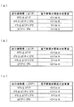
そして、室内機ユニット20の運転台数及び圧縮機11の指令回転数により、下記の条件(1)〜(3)に準じて図2に示す表A〜Cの中からひとつを選択する。なお、図2の数値はいずれも一例を示すものであり、これに限定されるものではない。
これらの表A〜Cは、上述した出口過熱度(ΔTIP)に対応する電子膨張弁14の開度変更量(パルス数)を定めた制御マップであり、それぞれの電子膨張弁14A,14Bについて、算出した出口過熱度(ΔTIP)に対応するパルス数だけ開度を増減して変更する。なお、上述した指令回転数は、室内機ユニット20A,20Bそれぞれの空調負荷に応じて、室外機ユニット10の圧縮機11に出される要求回転数であり、通常は空調負荷が大きいほど大きな値となる。
Then, one of the tables A to C shown in FIG. 2 is selected in accordance with the following conditions (1) to (3) according to the number of operating indoor unit units 20 and the command rotational speed of the compressor 11. In addition, all the numerical values of FIG. 2 show an example, and are not limited to this.
These Tables A to C are control maps that define the opening degree change amount (number of pulses) of the electronic expansion valve 14 corresponding to the above-described outlet superheat degree (ΔTIP). For each of the
(1)表Aを選択する条件
a.室内機ユニット20を1台のみ運転している場合
b.室内機ユニット20A,20Bを2台運転し、圧縮機11の指令回転数が2台共に 所定値R以上か、あるいは、圧縮機11の指令回転数が2台共に所定値R未満であ る場合
(2)表Bを選択する条件
室内機ユニット20A,20Bを2台運転し、いずれか一方の指令回転数だけが所定値 R未満の場合であって、指令回転数が所定値R以上の室内機ユニット
(3)表Cを選択する条件
室内機ユニット20A,20Bを2台運転し、いずれか一方の指令回転数だけが所定値 R未満の場合であって、指令回転数が所定値R未満の室内機ユニット
(1) Conditions for selecting Table A a. When only one indoor unit 20 is operating b. When two
上述した表から電子膨張弁開度の変更量SHが決まると、この変更量SHの積算値がゾーン制御実施後に決められた電子膨張弁開度Cpに加算される。すなわち、過熱制御実施後に分配される電子膨張弁14A,14Bの開度Cは、
C=Cp+ΣSH
で表される。
When the change amount SH of the electronic expansion valve opening is determined from the above-described table, the integrated value of the change amount SH is added to the electronic expansion valve opening Cp determined after the zone control is performed. That is, the opening degree C of the
C = Cp + ΣSH
It is represented by
たとえば、上述した(2)の条件により図2の表Bが選択される室内機ユニット20の場合、算出した出口過熱度(ΔTIP)が12℃以上(12℃≦ΔTIP)であれば、電子膨張弁14の開度を+4パルスだけ補正する。なお、電子膨張弁14の開度を補正するパルス数は、正(+)が開度を増して開く方向であり、負(−)が開度を減らして閉じる方向となる。
また、上述した(3)の条件により図2の表Cが選択される室内機ユニット20の場合には、算出した出口過熱度(ΔTIP)が10℃以上(10℃≦ΔTIP)であれば、電子膨張弁14の開度を+5パルスだけ補正する。
For example, in the case of the indoor unit 20 in which Table B in FIG. 2 is selected according to the condition (2) described above, if the calculated outlet superheat degree (ΔTIP) is 12 ° C. or more (12 ° C ≦ ΔTIP), the electronic expansion The opening of the valve 14 is corrected by +4 pulses. In addition, the number of pulses for correcting the opening degree of the electronic expansion valve 14 is a direction in which positive (+) increases the opening degree and opens, and negative (−) becomes a closing direction by reducing the opening degree.
Further, in the case of the indoor unit 20 in which the table C in FIG. 2 is selected according to the condition (3) described above, if the calculated outlet superheat degree (ΔTIP) is 10 ° C. or more (10 ° C ≦ ΔTIP), The opening degree of the electronic expansion valve 14 is corrected by +5 pulses.
すなわち、上述した開度補正の制御マップは、指令回転数が所定値より低く空調負荷の小さい室内機ユニット20側(表Cを適用)において、指令回転数が所定値より高く空調負荷の大きい室内機ユニット20側(表Bを適用)と比較した場合、出口過熱度が低い段階で大きなパルス数の開度補正を実施し、なるべく早く電子膨張弁14の開度を増して冷媒供給量が増加するように設定されている。そして、開度補正の変更量が0パルスになるまで、たとえば表Cの場合、出口過熱度が−5℃≦ΔTIP<0℃になるまで、フィードバック制御を繰り返す。 That is, in the above-described opening degree correction control map, on the indoor unit unit 20 side where the command rotational speed is lower than the predetermined value and the air conditioning load is small (Table C is applied), the room where the command rotational speed is higher than the predetermined value and the air conditioning load is large. When compared with the machine unit 20 side (applied to Table B), the opening degree correction with a large number of pulses is performed at the stage where the degree of outlet superheat is low, and the opening degree of the electronic expansion valve 14 is increased as soon as possible to increase the refrigerant supply amount. It is set to be. Then, the feedback control is repeated until the change amount of the opening degree correction becomes 0 pulse, for example, in the case of Table C, until the outlet superheat degree becomes −5 ° C. ≦ ΔTIP <0 ° C.
このため、冷媒循環量が少なく乾いた状態の室内熱交換機21は、この過熱度制御モードの実施により冷媒循環量が増加するので、その分過熱領域が減少し冷却能力も増加する。従って、空調負荷の小さい室内機ユニット20においても、室内熱交換機21の冷却能力が増すことにより、通過する室内気の湿分を凝縮させて除去することが可能になる。換言すれば、室内熱交換機21のフィンに結露して濡れた状態となるので、湿度の高い室内気がそのままランナ通路内に流入して結露するのを防止することができる。
なお、上述した過熱度制御モードの実施により、圧縮機11の適正な運転点から外れる可能性もあるが、この場合は、再度ゾーン制御を実施することで圧縮機の運転点を保護する制御は継続する。
For this reason, in the indoor heat exchanger 21 in a dry state with a small amount of refrigerant circulation, the amount of refrigerant circulation increases due to the execution of the superheat degree control mode, so the superheat region decreases and the cooling capacity increases accordingly. Therefore, even in the indoor unit 20 with a small air conditioning load, the humidity of the indoor heat exchanger 21 can be increased to condense and remove moisture from the passing indoor air. In other words, the dew condensation on the fins of the indoor heat exchanger 21 results in a wet state, so that indoor air with high humidity can be prevented from flowing into the runner passage as it is and dew condensation.
In addition, although there is a possibility of deviating from the proper operating point of the compressor 11 by performing the superheat degree control mode described above, in this case, the control for protecting the operating point of the compressor by performing the zone control again is performed. continue.
以上説明したように、本発明のマルチ型空気調和装置においては、2台ある室内熱交換機21A,21B毎に算出した出口過熱度から電子膨張弁14A,14Bの開度補正を個別に行う過熱度制御モードを備えているので、室内気ユニット20A,20Bの空調負荷が大きく異なっている場合であっても、冷媒分配量を修正して低負荷側における冷媒循環量の不足を解消することができる。この結果、ランナ結露を防止できるので、室内機ユニット20から結露水が水滴となって落下したり、あるいは、空調空気とともに水分が室内へ飛散するようなことはない。
なお、本発明は上述した実施形態に限定されるものではなく、本発明の要旨を逸脱しない範囲内において適宜変更することができる。
As described above, in the multi-type air conditioner of the present invention, the degree of superheat that individually corrects the opening of the
In addition, this invention is not limited to embodiment mentioned above, In the range which does not deviate from the summary of this invention, it can change suitably.
10 室外機ユニット
11 圧縮機
12 四方弁
13 室外熱交換器
14A,14B 電子膨張弁
20A,20B 室内機ユニット
21A,21B 室内熱交換機
23A,23B 二相流部温度センサ(第1の温度検出手段)
24A,24B 気相部温度センサ(第2の温度検出手段)
DESCRIPTION OF
24A, 24B Gas phase temperature sensor (second temperature detecting means)
Claims (1)
前記室内機ユニットの室内熱交換器が、それぞれ二相流部の温度を検出する第1の温度検出手段と、気相側の温度を検出する第2の温度検出手段とを備え、
冷房運転時に前記第1及び第2の温度検出手段で検出した温度差から各室内熱交換器毎に出口過熱度を算出し、該出口過熱度に基づいて前記室内機ユニット毎に前記電子膨張弁の開度を個別に補正する過熱度制御モードを備えていることを特徴とするマルチ型空気調和装置。 In a multi-type air conditioner comprising an outdoor unit and two indoor unit units connected to the indoor unit and each having its own electronic expansion valve,
The indoor heat exchanger of the indoor unit includes a first temperature detecting means for detecting the temperature of the two-phase flow section, and a second temperature detecting means for detecting the temperature on the gas phase side,
An outlet superheat degree is calculated for each indoor heat exchanger from the temperature difference detected by the first and second temperature detecting means during the cooling operation, and the electronic expansion valve is set for each indoor unit based on the outlet superheat degree. A multi-type air conditioner comprising a superheat degree control mode for individually correcting the opening degree of the air.
Priority Applications (1)
| Application Number | Priority Date | Filing Date | Title |
|---|---|---|---|
| JP2004103873A JP2005291553A (en) | 2004-03-31 | 2004-03-31 | Multi-type air conditioner |
Applications Claiming Priority (1)
| Application Number | Priority Date | Filing Date | Title |
|---|---|---|---|
| JP2004103873A JP2005291553A (en) | 2004-03-31 | 2004-03-31 | Multi-type air conditioner |
Publications (1)
| Publication Number | Publication Date |
|---|---|
| JP2005291553A true JP2005291553A (en) | 2005-10-20 |
Family
ID=35324681
Family Applications (1)
| Application Number | Title | Priority Date | Filing Date |
|---|---|---|---|
| JP2004103873A Pending JP2005291553A (en) | 2004-03-31 | 2004-03-31 | Multi-type air conditioner |
Country Status (1)
| Country | Link |
|---|---|
| JP (1) | JP2005291553A (en) |
Cited By (10)
| Publication number | Priority date | Publication date | Assignee | Title |
|---|---|---|---|---|
| KR100790050B1 (en) | 2006-09-04 | 2008-01-02 | 엘지전자 주식회사 | Control method of multi air conditioner |
| JP2009250479A (en) * | 2008-04-03 | 2009-10-29 | Sharp Corp | Air conditioner |
| JP2010216761A (en) * | 2009-03-18 | 2010-09-30 | Mitsubishi Heavy Ind Ltd | Multiple type air conditioner |
| EP2532992A1 (en) | 2011-06-09 | 2012-12-12 | Mitsubishi Heavy Industries | Multi-type air conditioner and control method therefor |
| JP2013047579A (en) * | 2011-08-29 | 2013-03-07 | Toshiba Corp | Air-conditioning control system and air-conditioning control method |
| US20130174591A1 (en) * | 2010-09-13 | 2013-07-11 | Carrier Corporation | Superheat control for a refrigerant vapor compression system |
| CN104006445A (en) * | 2013-02-26 | 2014-08-27 | 珠海格力电器股份有限公司 | Multi-connected air conditioner and control method thereof |
| CN105588284A (en) * | 2016-01-04 | 2016-05-18 | 广东美的暖通设备有限公司 | Method and device for controlling distribution of refrigerants of indoor units of air conditioning system |
| EP3199889A1 (en) * | 2016-01-28 | 2017-08-02 | Mitsubishi Heavy Industries Thermal Systems, Ltd. | Air conditioner |
| CN114963547A (en) * | 2021-05-25 | 2022-08-30 | 青岛海尔新能源电器有限公司 | Water heater control method, device, equipment and storage medium |
-
2004
- 2004-03-31 JP JP2004103873A patent/JP2005291553A/en active Pending
Cited By (11)
| Publication number | Priority date | Publication date | Assignee | Title |
|---|---|---|---|---|
| KR100790050B1 (en) | 2006-09-04 | 2008-01-02 | 엘지전자 주식회사 | Control method of multi air conditioner |
| JP2009250479A (en) * | 2008-04-03 | 2009-10-29 | Sharp Corp | Air conditioner |
| JP2010216761A (en) * | 2009-03-18 | 2010-09-30 | Mitsubishi Heavy Ind Ltd | Multiple type air conditioner |
| US20130174591A1 (en) * | 2010-09-13 | 2013-07-11 | Carrier Corporation | Superheat control for a refrigerant vapor compression system |
| EP2532992A1 (en) | 2011-06-09 | 2012-12-12 | Mitsubishi Heavy Industries | Multi-type air conditioner and control method therefor |
| JP2013047579A (en) * | 2011-08-29 | 2013-03-07 | Toshiba Corp | Air-conditioning control system and air-conditioning control method |
| CN104006445A (en) * | 2013-02-26 | 2014-08-27 | 珠海格力电器股份有限公司 | Multi-connected air conditioner and control method thereof |
| CN105588284A (en) * | 2016-01-04 | 2016-05-18 | 广东美的暖通设备有限公司 | Method and device for controlling distribution of refrigerants of indoor units of air conditioning system |
| EP3199889A1 (en) * | 2016-01-28 | 2017-08-02 | Mitsubishi Heavy Industries Thermal Systems, Ltd. | Air conditioner |
| CN114963547A (en) * | 2021-05-25 | 2022-08-30 | 青岛海尔新能源电器有限公司 | Water heater control method, device, equipment and storage medium |
| CN114963547B (en) * | 2021-05-25 | 2023-12-12 | 青岛海尔新能源电器有限公司 | Water heater control method, device, equipment and storage medium |
Similar Documents
| Publication | Publication Date | Title |
|---|---|---|
| JP6494765B2 (en) | Air conditioning system | |
| CN110671744B (en) | Air conditioner and constant temperature dehumidification control method thereof | |
| US20060254294A1 (en) | Air conditioner | |
| JP4849095B2 (en) | Air conditioner | |
| JPH04295568A (en) | air conditioner | |
| JP2011075179A (en) | Air conditioning system | |
| JP2016138666A (en) | Air conditioner | |
| JP2000274879A (en) | Air conditioner | |
| JP2005291553A (en) | Multi-type air conditioner | |
| JP5594030B2 (en) | Controller, humidity controller and air conditioning system | |
| JP3969381B2 (en) | Multi-room air conditioner | |
| JP2013002749A (en) | Air conditioning device | |
| JP2008157557A (en) | Air conditioner | |
| JP6938950B2 (en) | Air conditioning system | |
| JP2008175430A (en) | Air conditioner | |
| JP7374633B2 (en) | Air conditioners and air conditioning systems | |
| JP4074422B2 (en) | Air conditioner and its control method | |
| JP4785508B2 (en) | Air conditioner | |
| JP4647399B2 (en) | Ventilation air conditioner | |
| KR20190088693A (en) | Method for controlling multi-type air conditioner | |
| WO2019155614A1 (en) | Air-conditioning device, air-conditioning system, and heat exchange unit | |
| JP4391188B2 (en) | Air conditioner | |
| JP2018071864A (en) | Air conditioner | |
| JP2006234295A (en) | Multi-type air conditioner | |
| JP2006234296A (en) | Multi-type air conditioner |
Legal Events
| Date | Code | Title | Description |
|---|---|---|---|
| A621 | Written request for application examination |
Free format text: JAPANESE INTERMEDIATE CODE: A621 Effective date: 20061117 |
|
| A977 | Report on retrieval |
Free format text: JAPANESE INTERMEDIATE CODE: A971007 Effective date: 20080729 |
|
| A131 | Notification of reasons for refusal |
Free format text: JAPANESE INTERMEDIATE CODE: A131 Effective date: 20080805 |
|
| A02 | Decision of refusal |
Free format text: JAPANESE INTERMEDIATE CODE: A02 Effective date: 20090217 |