JP2005290694A - Wall body ventilating member, building wall body, and building - Google Patents
Wall body ventilating member, building wall body, and building Download PDFInfo
- Publication number
- JP2005290694A JP2005290694A JP2004103634A JP2004103634A JP2005290694A JP 2005290694 A JP2005290694 A JP 2005290694A JP 2004103634 A JP2004103634 A JP 2004103634A JP 2004103634 A JP2004103634 A JP 2004103634A JP 2005290694 A JP2005290694 A JP 2005290694A
- Authority
- JP
- Japan
- Prior art keywords
- ventilation
- wall
- building
- lateral groove
- wall body
- Prior art date
- Legal status (The legal status is an assumption and is not a legal conclusion. Google has not performed a legal analysis and makes no representation as to the accuracy of the status listed.)
- Granted
Links
- 238000009423 ventilation Methods 0.000 claims abstract description 314
- 239000000463 material Substances 0.000 claims abstract description 62
- 238000009413 insulation Methods 0.000 claims description 19
- 230000002349 favourable effect Effects 0.000 abstract 1
- 230000000903 blocking effect Effects 0.000 description 9
- 238000005187 foaming Methods 0.000 description 9
- 239000006260 foam Substances 0.000 description 7
- 229910052602 gypsum Inorganic materials 0.000 description 6
- 239000010440 gypsum Substances 0.000 description 6
- 230000002093 peripheral effect Effects 0.000 description 6
- 239000002023 wood Substances 0.000 description 6
- 239000002184 metal Substances 0.000 description 5
- 229910052751 metal Inorganic materials 0.000 description 5
- 238000003763 carbonization Methods 0.000 description 4
- 239000004088 foaming agent Substances 0.000 description 4
- 229920006015 heat resistant resin Polymers 0.000 description 4
- 239000011342 resin composition Substances 0.000 description 4
- 238000004891 communication Methods 0.000 description 3
- 238000010276 construction Methods 0.000 description 3
- 229910010272 inorganic material Inorganic materials 0.000 description 3
- 239000011147 inorganic material Substances 0.000 description 3
- 238000003780 insertion Methods 0.000 description 3
- 230000037431 insertion Effects 0.000 description 3
- 239000011810 insulating material Substances 0.000 description 3
- 238000000034 method Methods 0.000 description 3
- 230000009471 action Effects 0.000 description 2
- 230000004888 barrier function Effects 0.000 description 2
- 239000011230 binding agent Substances 0.000 description 2
- 239000003795 chemical substances by application Substances 0.000 description 2
- 239000000945 filler Substances 0.000 description 2
- 230000009970 fire resistant effect Effects 0.000 description 2
- 238000005304 joining Methods 0.000 description 2
- 239000004033 plastic Substances 0.000 description 2
- 239000004014 plasticizer Substances 0.000 description 2
- 239000011120 plywood Substances 0.000 description 2
- RNFJDJUURJAICM-UHFFFAOYSA-N 2,2,4,4,6,6-hexaphenoxy-1,3,5-triaza-2$l^{5},4$l^{5},6$l^{5}-triphosphacyclohexa-1,3,5-triene Chemical compound N=1P(OC=2C=CC=CC=2)(OC=2C=CC=CC=2)=NP(OC=2C=CC=CC=2)(OC=2C=CC=CC=2)=NP=1(OC=1C=CC=CC=1)OC1=CC=CC=C1 RNFJDJUURJAICM-UHFFFAOYSA-N 0.000 description 1
- OKTJSMMVPCPJKN-UHFFFAOYSA-N Carbon Chemical compound [C] OKTJSMMVPCPJKN-UHFFFAOYSA-N 0.000 description 1
- 241001379910 Ephemera danica Species 0.000 description 1
- ISWSIDIOOBJBQZ-UHFFFAOYSA-N Phenol Chemical compound OC1=CC=CC=C1 ISWSIDIOOBJBQZ-UHFFFAOYSA-N 0.000 description 1
- 230000004308 accommodation Effects 0.000 description 1
- 230000008901 benefit Effects 0.000 description 1
- 229910052799 carbon Inorganic materials 0.000 description 1
- 238000010000 carbonizing Methods 0.000 description 1
- 239000011248 coating agent Substances 0.000 description 1
- 238000000576 coating method Methods 0.000 description 1
- 239000013065 commercial product Substances 0.000 description 1
- 238000005520 cutting process Methods 0.000 description 1
- 238000006073 displacement reaction Methods 0.000 description 1
- 230000000694 effects Effects 0.000 description 1
- 229920006248 expandable polystyrene Polymers 0.000 description 1
- 239000004794 expanded polystyrene Substances 0.000 description 1
- 239000000835 fiber Substances 0.000 description 1
- 239000003063 flame retardant Substances 0.000 description 1
- 239000011491 glass wool Substances 0.000 description 1
- PCHJSUWPFVWCPO-UHFFFAOYSA-N gold Chemical compound [Au] PCHJSUWPFVWCPO-UHFFFAOYSA-N 0.000 description 1
- 239000010931 gold Substances 0.000 description 1
- 229910052737 gold Inorganic materials 0.000 description 1
- 238000010438 heat treatment Methods 0.000 description 1
- 230000006872 improvement Effects 0.000 description 1
- 238000007373 indentation Methods 0.000 description 1
- 238000009434 installation Methods 0.000 description 1
- 238000003754 machining Methods 0.000 description 1
- 239000011490 mineral wool Substances 0.000 description 1
- 238000005192 partition Methods 0.000 description 1
- 230000035515 penetration Effects 0.000 description 1
- 230000000704 physical effect Effects 0.000 description 1
- 230000005855 radiation Effects 0.000 description 1
- 230000000630 rising effect Effects 0.000 description 1
- 238000007789 sealing Methods 0.000 description 1
- 239000007787 solid Substances 0.000 description 1
- 230000007480 spreading Effects 0.000 description 1
- 238000003892 spreading Methods 0.000 description 1
- 229920003002 synthetic resin Polymers 0.000 description 1
- 239000000057 synthetic resin Substances 0.000 description 1
Images


Landscapes
- Building Environments (AREA)
- Load-Bearing And Curtain Walls (AREA)
Abstract
Description
本発明は、床下空間と小屋裏空間との通気をとる壁体内通気路を有した建物の壁体、及びこの壁体に前記通気のために用いられる通気部材、並びに前記壁体を備える建物に関する。 The present invention relates to a wall of a building having a wall ventilation path that allows ventilation between the underfloor space and the attic space, a ventilation member used for the ventilation in the wall, and a building including the wall. .
従来、断熱を施した住宅で、壁体内通気路に配設された端根太、転び止め、側根太、添え側根太等の横架材の側面に、縦方向の通気切欠きを横架材の長手方向に沿って間隔的に複数設けて、床下空間と小屋裏空間との通気を可能とした技術が知られている(例えば、特許文献1参照。)。
特許文献1は、壁体内通気路での通気の邪魔となるように配置された横架材を上下方向に通って通気ができるようにした技術を開示しているに過ぎず、横架材が延びる方向である水平方向に通気経路を確保することについては言及していない。 Patent Document 1 merely discloses a technique in which ventilation is allowed to pass through a horizontal member arranged in the vertical direction so as to obstruct ventilation in the ventilation passage in the wall. No mention is made of securing the ventilation path in the horizontal direction, which is the extending direction.
通常、壁体の一部には窓を設けるための開口部が設けられる。この開口部を区画する窓台やまぐさなどの水平棒材が、前記横架材の上面又は下面に接して設けられると、この水平棒材によって横架材の通気切欠きが閉じられて、壁体内の熱や湿気を排出する壁体内通気が途絶えてしまうので、その改善が求められている。 Usually, an opening for providing a window is provided in a part of the wall. When a horizontal bar material such as a window sill or a lintel that divides this opening is provided in contact with the upper surface or the lower surface of the horizontal member, the horizontal member closes the ventilation notch of the horizontal member, and the wall Improvement in the ventilation of the wall, which exhausts heat and moisture in the body, is required.
この対策として、閉ざされた通気路部分とこれに隣接した他の通気路部分とを仕切る縦部材に、両通気路部分を連通する切欠きを設けることが行われている。しかし、前記切欠きの加工は、施工現場などでのみを用いて削る作業であるので、施工上好ましくない。 As a countermeasure, a notch for communicating the two air passage portions is provided in a vertical member that partitions the closed air passage portion and another air passage portion adjacent to the closed air passage portion. However, the machining of the notch is not preferable in terms of construction because it is a work that uses only the construction site.
他の対策として、本発明者は、横架材に、その縦方向の通気切欠きと交差して横方向に延びる他の通気切欠きを設けることを考えた。しかし、この対策は、開口部を迂回する壁体内通気が可能にはなるものの、横架材の強度を低下させるとともに、横架材に対する切欠きの加工も大変であるという点で実際的ではない。 As another countermeasure, the present inventor considered that the horizontal member is provided with another ventilation notch that extends in the lateral direction so as to intersect with the longitudinal ventilation notch. However, although this measure enables ventilation in the wall that bypasses the opening, it reduces the strength of the horizontal member and is not practical in that it is difficult to cut out the horizontal member. .
又、木造の建物の中には、壁体での断熱のための断熱層の内面が構造用の面材で被われた壁体を備えるものが知られている。この壁体では、面材が上下方向に複数に分かれているので、防耐火性能の観点で、それらの合わせ目について目地処理を行う場合がある。しかし、目地処理のために使用される従来の目地止め部材は、壁体内の通気とは無関係に用いられているに過ぎない。 Some wooden buildings have a wall body in which the inner surface of a heat insulating layer for heat insulation in the wall body is covered with a structural surface material. In this wall, since the face material is divided into a plurality of parts in the vertical direction, joint processing may be performed on the joints from the viewpoint of fireproof performance. However, the conventional joint fixing member used for joint treatment is only used independently of ventilation in the wall.
本発明の目的は、壁体内の通気を妨げる構造を壁体が有していても、壁体内通気を実使用上好ましい形態で確保するのに好適な壁体の通気部材、壁体内の通気を妨げる構造を壁体が有していても、壁体内通気を実使用上好ましい形態で確保できる建物の壁体、及びこの壁体を備えた建物を提供することにある。 An object of the present invention is to provide a ventilation member for a wall suitable for securing the ventilation in the wall in a preferable form for practical use, even if the wall has a structure that prevents ventilation in the wall. An object of the present invention is to provide a wall of a building that can ensure ventilation in the wall in a form that is preferable for practical use, even if the wall has a blocking structure, and a building including the wall.
前記課題を解決するために、本発明に係る壁体の通気部材は、床下空間と小屋裏空間とにわたる壁体内通気路を設けた壁体が備える通気部材であって、屋外側に凹んでいるとともに水平方向に連続して延びて前記壁体内通気路に連通する通気横溝を有していることを特徴としている。 In order to solve the above-mentioned problems, a wall ventilation member according to the present invention is a ventilation member provided in a wall body provided with a wall ventilation path extending between an under-floor space and a shed space, and is recessed outward. In addition, it has a ventilation lateral groove that extends continuously in the horizontal direction and communicates with the wall ventilation path.
本発明及び以下の各発明で、通気部材は、金属、合成樹脂、又は木材、或いは無機材等により形成できる。本発明の通気部材は、水平方向に延びた通気横溝を、床下空間と小屋裏空間とにわたる壁体内通気路に連通させて使用される。このため、壁体の窓等の壁体内通気を妨げる構造(通気遮断物)によって壁体内通気路の一部の通気がせき止められても、前記壁体内通気を妨げる構造に対して水平方向にずれた隣接位置で通気が確保されている壁体内通気路部分に、せき止められた空気を通気横溝に通して導くことができる。これにより、床下空間と小屋裏空間とにわたる壁体内通気を確保できる。 In the present invention and each of the following inventions, the ventilation member can be formed of metal, synthetic resin, wood, inorganic material, or the like. The ventilation member according to the present invention is used by allowing a horizontal ventilation groove extending in the horizontal direction to communicate with a ventilation passage in the wall extending between the underfloor space and the cabin space. For this reason, even if a part of the ventilation passage in the wall is blocked by a structure (ventilation blockage) that prevents the ventilation of the wall, such as a window of the wall, the horizontal displacement with respect to the structure that prevents the ventilation in the wall It is possible to guide the dammed air through the ventilation lateral groove to the in-wall ventilation path portion where ventilation is ensured at the adjacent position. Thereby, ventilation in the wall over the underfloor space and the attic space can be secured.
又、前記課題を解決するために、本発明に係る壁体の通気部材は、床下空間と小屋裏空間とにわたる壁体内通気路をこの通気路の屋外側で被った面材に対し上下方向に連続して配置される通気部材であって、屋外側に凹んでいるとともに水平方向に連続して延びて前記壁体内通気路に連通する通気横溝と、この横溝に連続して前記面材の縁部裏面に重なるフランジと、を備えたことを特徴としている。 In order to solve the above-mentioned problem, the wall ventilation member according to the present invention is provided in a vertical direction with respect to the face material covered on the outdoor side of the ventilation path between the underfloor space and the cabin space. A ventilation member continuously disposed, which is recessed to the outdoor side and extends continuously in the horizontal direction and communicates with the ventilation passage in the wall, and an edge of the face material continuous with the transverse groove And a flange that overlaps the back of the part.
本発明で、通気部材のフランジは、通し柱等の柱に直角に連結される胴差しやこの胴差しと平行に配置される部材等の横架材の設置個所に応じて通気横溝の少なくとも一方の溝縁から折れ曲がるように連続して設ければよい。 In the present invention, the flange of the ventilation member has at least one of the ventilation lateral grooves according to the installation position of a horizontal member such as a trunk inserted at right angles to a pillar such as a through pillar or a member arranged in parallel with the trunk. What is necessary is just to provide continuously so that it may bend from a groove edge.
本発明の通気部材は、水平方向に延びた通気横溝を、床下空間と小屋裏空間とにわたる壁体内通気路に連通させて使用される。このため、壁体の窓等の壁体内通気を妨げる構造によって壁体内通気路の一部の通気がせき止められても、前記壁体内通気を妨げる構造に対して水平方向にずれた隣接位置で通気が確保されている壁体内通気路部分に、前記壁体内通気を妨げる構造でせき止められた空気を通気横溝に通して導くことができる。これにより、床下空間と小屋裏空間とにわたる壁体内通気を確保できる。更に、通気部材はその通気横溝に連続したフランジにより面材等に取付けることができる。しかも、この通気部材は面材の縁部をこの裏面から被って面材に対し上下方向に連続して配置されるので、目地止め部材として機能できる。 The ventilation member according to the present invention is used by allowing a horizontal ventilation groove extending in the horizontal direction to communicate with a ventilation passage in the wall extending between the underfloor space and the cabin space. For this reason, even if a part of the ventilation path of the wall is blocked by the structure that prevents the ventilation in the wall such as the window of the wall, the ventilation is performed at an adjacent position shifted in the horizontal direction with respect to the structure that prevents the ventilation in the wall. The air blocked by the structure that prevents the ventilation in the wall can be guided through the ventilation lateral groove to the in-wall ventilation path portion where the airflow is secured. Thereby, ventilation in the wall over the underfloor space and the attic space can be secured. Further, the ventilation member can be attached to a face material or the like by a flange continuous with the ventilation lateral groove. Moreover, since this ventilation member covers the edge of the face material from the back surface and is continuously arranged in the vertical direction with respect to the face material, it can function as a joint-preventing member.
又、本発明の好ましい形態では、通気部材を不燃材製としている。ここに、不燃材とは、建築基準法第2条第9項で定められた不燃材料に適合する材料で作られた部材を指し、不燃材として金属を好適に使用できる。この好ましい形態の発明では、目地止め部材として機能する通気部材の不燃性によって、火災時に火炎が目地部を通ることを抑制できる。
Moreover, in the preferable form of this invention, the ventilation member is made from a nonflammable material. Here, the non-combustible material refers to a member made of a material that conforms to the non-combustible material defined in
又、本発明の好ましい形態では、所定温度以下では前記壁体内通気路の通気を許す状態を維持し、所定温度を超える温度では前記壁体内通気路の通気を遮断するように発泡膨張する閉塞要素を、前記通気横溝の内面と外面との内の少なくとも内面に設けている。 Further, in a preferred embodiment of the present invention, an obstructing element that expands and expands so as to maintain the state in which the ventilation of the wall ventilation path is allowed at a predetermined temperature or less and to block the ventilation of the wall ventilation path at a temperature exceeding the predetermined temperature. Are provided on at least the inner surface of the inner surface and the outer surface of the ventilation lateral groove.
この好ましい形態の発明では、火災時に熱で閉塞要素が加熱されてその温度が所定温度を超えると、閉塞要素が発泡膨張して通気横溝の通気を絶って、壁体内通気路の通気を遮断できるので、壁体内通気路を経由する延焼を抑制できる。 In this preferred embodiment of the invention, when the closing element is heated by heat in the event of a fire and the temperature exceeds a predetermined temperature, the closing element foams and expands and the ventilation lateral groove is cut off, whereby the ventilation of the ventilation path in the wall can be blocked. As a result, it is possible to suppress the spread of fire through the ventilating passage in the wall.
又、前記課題を解決するために、本発明に係る建物の壁体は、床下空間と小屋裏空間とを連通する壁体内通気路を断熱層の内側に有し、前記断熱層の内面が面材で被われた建物の壁体において、建物の外周に沿って水平方向に置かれて側面に前記床下空間と小屋裏空間とにわたる通気のための縦溝を有した横架材と、前記縦溝に対して交差関係を持って連通し水平方向に延びる通気横溝を有して前記横架材の側面にこの横架材の長手方向に沿って配置された通気部材と、を具備したことを特徴としている。 In order to solve the above-mentioned problems, the wall of the building according to the present invention has a wall ventilation passage that communicates the underfloor space and the shed space inside the heat insulation layer, and the inner surface of the heat insulation layer is a surface. In a wall of a building covered with a material, a horizontal member placed in a horizontal direction along the outer periphery of the building and having a vertical groove on the side surface for ventilation between the underfloor space and the attic space; A ventilation member that has a ventilation transverse groove that communicates in a crossing relationship with the groove and extends in the horizontal direction, and is disposed on a side surface of the horizontal member along the longitudinal direction of the horizontal member. It is a feature.
本発明では、通気のための縦溝を複数有した横架材の側面に沿って通気部材を配置し、この通気部材の水平方向に延びた通気横溝と横架材の縦溝とを交わらせて、これらの溝を連通させて、壁体内での通気構造を構成している。このため、壁体の窓等の壁体内通気を妨げる構造によって横架材の一部の縦溝がせき止められることがあっても、前記壁体内通気を妨げる構造に対して水平方向にずれた隣接位置で通気が確保されている横架材の縦溝に、前記壁体内通気を妨げる構造でせき止められた空気を通気横溝に通して導くことができる。これにより、床下空間と小屋裏空間とにわたる壁体内通気を確保できる。 In the present invention, the ventilation member is disposed along the side surface of the horizontal member having a plurality of vertical grooves for ventilation, and the horizontal ventilation groove of the ventilation member and the vertical groove of the horizontal member are crossed. Thus, these grooves are connected to form a ventilation structure in the wall. For this reason, even if some vertical grooves of the horizontal member may be blocked by the structure that prevents the ventilation in the wall such as the window of the wall, the adjacently shifted in the horizontal direction with respect to the structure that prevents the ventilation in the wall The air blocked by the structure that prevents the ventilation in the wall can be guided through the ventilation lateral groove to the vertical groove of the horizontal member in which ventilation is ensured at the position. Thereby, ventilation in the wall over the underfloor space and the attic space can be secured.
又、本発明の好ましい形態では、前記通気部材に前記請求項1から4の内のいずれか1項に記載の通気部材を用いている。 In a preferred embodiment of the present invention, the ventilation member according to any one of claims 1 to 4 is used as the ventilation member.
この好ましい形態の発明では、通気部材をそのフランジにより面材等に取付けることができて、この通気部材は面材を目地止め部材として用いることができ、或いは、火災時に火炎が目地部を通ることを抑制でき、若しくは、火災時に熱で発泡膨張する閉塞要素によって壁体内通気路の通気を遮断して、壁体内通気路を経由する延焼を抑制できる。 In the invention of this preferred embodiment, the ventilation member can be attached to the face material or the like by the flange, and the ventilation member can use the face material as a joint sealing member, or a flame passes through the joint part at the time of a fire. In addition, it is possible to suppress the passage of air through the wall ventilation path by a closing element that foams and expands with heat in the event of a fire, and to suppress the spread of fire through the wall ventilation path.
又、本発明の好ましい形態では、隅部をなして隣接する壁部が有した前記通気部材を、前記隅部において通気横溝を互に連通して接合させている。 In a preferred embodiment of the present invention, the ventilation member having the corner portion and the adjacent wall portion has the ventilation lateral groove communicated with each other at the corner portion.
この好ましい形態の発明では、建物の外周に水平方向に沿って通気横溝が連続して、壁体での出隅部や入隅部での通気が可能となるので、壁体内通気の信頼性を向上できる。 In the invention of this preferred embodiment, the ventilation lateral groove is continuous along the horizontal direction on the outer periphery of the building, and ventilation at the protruding corner portion and the entering corner portion of the wall body is possible. It can be improved.
又、前記課題を解決するために、本発明に係る建物は、前記各発明の内のいずれかの発明に係る壁体を具備しているので、既述の作用を得て、壁体内の通気を妨げる構造を壁体が有していても、壁体内通気を実使用上好ましい形態で確保することが可能な壁体を備えた建物を提供できる。 Moreover, in order to solve the said subject, since the building which concerns on this invention has comprised the wall body which concerns on either invention among each said invention, it obtains the effect | action mentioned above and ventilates in a wall body. Even if the wall has a structure that prevents the wall, it is possible to provide a building including a wall that can ensure ventilation in the wall in a form that is preferable in practical use.
本発明によれば、壁体内の通気を妨げる構造を壁体が有していても、壁体内通気を実使用上好ましい形態で確保するのに好適な壁体の通気部材を提供できる。 ADVANTAGE OF THE INVENTION According to this invention, even if a wall has the structure which interrupts | blocks ventilation | gas_flowing in a wall body, the ventilation member of a wall body suitable for ensuring ventilation in a wall body with a preferable form on practical use can be provided.
又、本発明によれば、壁体内の通気を妨げる構造を壁体が有していても、壁体内通気を実使用上好ましい形態で確保できる建物の壁体、及びこの壁体を備えた建物を提供できる。 Moreover, according to the present invention, even if the wall has a structure that prevents ventilation in the wall, the wall of the building that can ensure the ventilation in the wall in a preferable form for practical use, and the building including the wall Can provide.
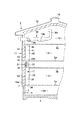
図面を参照して本発明の一実施形態に係る在来軸組構造の二階建て木造住宅を説明する。 A conventional two-story wooden house according to an embodiment of the present invention will be described with reference to the drawings.
図1中に示すように住宅1が備えるコンクリート製の基礎2は、その内側に床下空間2aを形成する。この床下空間2aを断熱するために、基礎2の主体をなす基礎コンクリートの屋外面又は屋内面の内の少なくとも一方に断熱層(図示しない)が被着されている。基礎2は1以上の床下換気口3を有している。この床下換気口3を開閉する床下ダンパー4が基礎2に取付けられている。床下ダンパー4は手動又は電動により任意に開閉される。符号5は基礎2上に構築された階下居室として1階居室を示している。符号6は1階居室5上に構築された階上居室として2階居室を示している。なお、符号5aは床下空間2aに臨んだ1階居室5の床板、5bは1階居室5の天井板を示している。符号6aは2階居室6の床板、6bは小屋裏空間13に臨んだ2階居室6の天井板を示している。又、図1中符号7は土台を示している。
As shown in FIG. 1, the
居室5,6は住宅1の外郭で被われている。外郭は、壁体11及び屋根12等を備えている。壁体11は1、2階の居室5、6を囲んで設けられている。屋根12は壁体11の上側に連続して設けられていて、この屋根12と最上階の2階居室6との間には小屋裏空間13が形成されている。
The
前記外郭は、壁体11の断熱のための断熱層15と、この断熱層15を間に置いて設けられた外側通気路16と壁体内通気路17とを備えている。断熱層15には、プラスチック系断熱材例えば独立発泡された発泡ポリスチレンを一層又は複層したボードを好適に使用でき、この他に難燃性又は不燃性のフェノールフォーム、ALC、又はグラスウールやロックウールなどの繊維系断熱材を層状としたものも使用可能である。断熱層15の内側に、居室5,6、小屋裏空間13、及び壁体11の壁体内通気路17が設けられている。
The outer shell includes a
住宅1の上部に、断熱層15によって外側通気路16から区画された小屋裏空間13と屋外との連通を開閉する換気部として例えば強制換気装置18が設けられている。強制換気装置18は、小屋裏空間13と屋外とを連通した排気路18aと、この排気路18a中に少なくともファンが配置された電動式の換気扇18bと、この換気扇18bの好ましくは下流側に配置されて排気路18aを開閉する排気ダンパー18cとを有して形成されている。強制換気装置18等からなる換気部は、排気ダンパー18cを備えない構成でもよい。更に、換気部は、手動又は電動により開閉されてその開放により自然換気をする排気ダンパーであってもよく、更に、ドレーキップ窓や天窓などの開口部開閉要素のような通常の建具も包含する。
For example, a forced ventilation device 18 is provided in the upper part of the house 1 as a ventilation part that opens and closes communication between the
外側通気路16は、断熱層15と壁体11の外装材14及び屋根材との間にこれらに沿って形成されている。外側通気路16の下端16aは、常時開口されていて、屋外の大気中に連通されている。屋根12の上部には屋外に連通されるように開放された排気部19が設けられていて、この排気部19に外側通気路16の上端部が連通されている。
The
壁体内通気路17は、住宅1の躯体をなす通し柱等の柱21(図5参照)及び胴差し22を利用して、断熱層15と居室5,6との間にこれらに沿って形成されていて、床下空間2aと小屋裏空間13とを連通している。垂直棒材である柱21は住宅1の外周部に垂直に延びて配置されている。胴差し22は、横架材として機能するものであって、その端を柱21に連結して住宅1の外周部に沿って水平方向に配置されている。
The in-
図4等に示すように胴差し22の屋外側の側面に、複数の縦溝22aとこれに隣接する複数の凸部22bとが交互に所定間隔で設けられている。上下方向に延びる縦溝22aは、床下空間2aと小屋裏空間13とに渡る壁体内通気を許すための切欠きであって、胴差し22の上下両面に夫々開放している。各縦溝22aの幅は10mm〜100mm、好ましくは20mm〜60mm、各縦溝22aの深さは5mm〜30mm、好ましくは7mm〜15mm、胴差し22の厚みに応じた各縦溝22aの長さは幅150mm〜500mmが好ましい。
As shown in FIG. 4 and the like, a plurality of
なお、図5中符号23は胴差し22等の横架材に上下両端を固定して柱21間に上下方向に延びて設けられた間柱を示しており、更に、図5中符号24は胴差し22に対し上下方向に連続して配置された窓を示している。図示例の窓24は、その窓台24aを胴差し22の上面に接して配置されている。窓24は、壁体内通気路の一部の通気を止める通気遮断物の一例であって、図5の例とは逆に窓24のまぐさ(図示しない)を胴差し22の下面に接して配置される場合もある。
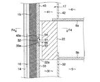
壁体内通気路17は、階下側通気路部分31と、階上側通気路部分41と、これらの通気路部分31,41を連通して設けられた連通構造(縦溝22a及び通気横溝52)とで形成されている。
The in-
階下側通気路部分31は、柱21及び胴差し22の屋内側の面に周部を釘打ち等により固定されて耐火性内被材として機能する例えば石膏ボード32と、柱21及び胴差し22の屋外側の面側に周部を釘打ち等により固定された面材33との間に形成されている。この階下側通気路部分31は、その下端の通気部例えば床板5aの延出部に開けた通孔34を通じて床下空間2aと連通している。垂直面材である石膏ボード32は1階居室5に臨んでいる。垂直面材である面材33には、厚さが2mm〜24mmの構造用合板、木質系パネル、例えば無機質材料からなる不燃性パネル等が用いられている。この面材33は断熱層15の中で1階居室5に対応する断熱層部分に接している。
The
階上側通気路部分41は、柱21及び胴差し22の屋内側の面に周部を釘打ち等により固定されて耐火性内被材として機能する例えば石膏ボード42と、柱21及び胴差し22の屋外側の面側に周部を釘打ち等により固定された面材43との間に形成されている。この階上側通気路部分41は、その上端の通気部例えば天井6bの延出部に開けた通孔44を通じて小屋裏空間13と連通している。垂直面材である石膏ボード42は2階居室6に臨んでいる。垂直面材である面材43にも、面材33と同様に厚さが2mm〜24mmの構造用合板、木質系パネル、例えば無機質材料からなる不燃性パネル等が用いられている。この面材43は断熱層15の中で2階居室6に対応する断熱層部分に接している。
For example,
面材33,43には、本実施形態では一枚板を用いたが、夫々複数の面材要素を上下方向に連続させて構成することもできる。又、胴差し22の側面に打付けられる面材33,43間に、通気部材51の後述する通気溝部52の上方又は下方に連続して胴差し22に打付けられる他の面材を追加して設けることもできる。この追加された面材は、これに上方又は下方に連続する面材とともに壁体内通気路17を屋外側から覆うものであって、具体的には、縦溝22aを被って配置される。
In the present embodiment, a single plate is used for the
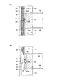
縦溝22aを有した胴差し22の側面に打付けられた下側の面材33の縁部33aと、同じく胴差し22の前記側面に打付けられた下側の面材43の縁部43aとは、互に離れている。互に隣接した縁部33a,43a間には、これらに対し上下方向に連続する通気部材51が設けられている。
An
通気部材51は、好適な例として不燃材、例えば釘打ち可能な厚さの金属で作られている。図2及び図3に示すように通気部材51は、通気横溝52と、例えば一対のフランジ53,54と、閉塞要素55とを備えている。
The
通気横溝52は、屋外側に凹んで断面略コ字状をなしていて、水平方向に連続して延びている。フランジ53,54は通気横溝52の長手方向に延びる開口縁から互に遠ざかる方向に折れ曲がって通気横溝52に連続している。通気横溝52のフランジ53,54に対する出幅Aは、面材33,43の厚みBと略同じであるが、A≦Bとすることは、A>Bとした場合に比較して、通気横溝52を原因としてこれに対向した断熱層15の部分が屋外側に突出する不陸状態を形成されないようにできる点で好ましい。
The
通気部材51は、その通気横溝52を面材33,43の縁部33a,43a間に配置し、かつ、一方のフランジ53を縁部33aの裏面に重ねて複数の釘56で縁部33aに固定するとともに、他方のフランジ54を縁部43aの裏面に重ねて複数の釘57で縁部43aに固定して設けられている。これにより、通気部材51は胴差し22の側面にこの胴差し22の長手方向に沿って配置される。この通気部材51の通気横溝52は、図5に示すように胴差し22の各縦溝22aに対して略直交する関係を持って、これら縦溝22aと連通されている。したがって、通気横溝52と壁体内通気路17とは連通している。
The
なお、通気部材51は以上のように面材33,43に固定することに代えて、フランジ53,54等を通る釘によって胴差し22の側面に打付けてもよい。更に、こうして胴差し22にその側面に沿って固定された通気部材51のフランジ53,54に面材33,43の縁部33a,43aを重ねて、これらを通る釘によって胴差し22の側面に縁部33a,43aを打付けてもよい。
The
閉塞要素55は通気横溝52の内面と外面との内の少なくとも内面に取付けられている。この閉塞要素55は、テープ状又は紐状などのように細長い形状をなしていて、通気横溝52の長手方向略全体にわたって連続して貼り付け等により設けられている。この閉塞要素55は、所定温度以下では壁体内通気路17の通気(具体的には縦溝22aを通る通気)を許す状態を維持し、所定温度を超える温度では壁体内通気路17の通気(具体的には縦溝22aを通る通気)を遮断するように発泡膨張するものであって、本実施形態では未発泡の耐火性発泡剤を使用している。
The closing
この発泡剤としては、炭化成分、炭化促進剤、発泡主剤、及びバインダ、そして必要に応じて添加される可塑剤、並びに充填剤を含む耐熱性樹脂組成物を例示できる。炭化成分はカーボンを生成させる主成分である。炭化促進剤は炭化成分のカーボン化を促進させる成分である。発泡主剤は発泡膨張を担う主成分である。バインダは前記各材料を結合して耐熱性樹脂組成物の物性を改善するものである。そして、可塑剤は、耐熱性樹脂組成物に柔軟性を付与して塗膜の成形性を高める機能を有し、充填剤は、耐熱性樹脂組成物の不燃性を高めかつ気泡密度を高める機能を有する。 Examples of the foaming agent include a heat-resistant resin composition containing a carbonizing component, a carbonization accelerator, a foaming main agent, and a binder, and a plasticizer added as necessary, and a filler. A carbonization component is a main component which produces | generates carbon. The carbonization accelerator is a component that promotes carbonization of the carbonized component. The foaming main agent is a main component responsible for foam expansion. The binder improves the physical properties of the heat resistant resin composition by combining the above materials. The plasticizer has a function of imparting flexibility to the heat-resistant resin composition to increase the moldability of the coating film, and the filler has a function of increasing the nonflammability of the heat-resistant resin composition and increasing the cell density. Have
未発泡の耐火性発泡剤からなる閉塞要素55は、支持材をなす木材の耐熱温度以下の所定温度で発泡膨張して、この発泡膨張を完了する性能を有している。前記発泡膨張を開始する温度は、例えば60℃〜250℃、好ましくは200℃〜250℃であり、この温度を超える温度では発泡膨張が完了して、この発泡膨張により、縦溝22aを通る通気が実質的に遮断されるようになっている。なお、閉塞要素55をなす発泡剤には、前記例示のものの他に、熱で燃えて、膨らんで、この膨らみ状態で固体となる一般市販品を用いることができる。
The closing
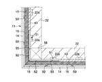
図6に示すように壁体11の隣接する壁部がなす隅部において、各壁部に沿って水平方向の延びている通気部材51の端部は、それらの通気横溝52を互に連通して接合されている。この接合のために、例えば通気部材51の端部はいわゆる額縁継ぎされているが、接合方法は、これには限定されない。なお、図6は出隅である場合を示しているが、入隅の場合も同様である。又、図6中符号58は胴差し22の端を支持する隅柱を示している。
As shown in FIG. 6, at the corners formed by the adjacent wall portions of the
前記断熱層15の外面には、上下方向に連続して延びる複数本の縦胴縁59(図4及び図6参照)が、住宅1の外周に沿って所定間隔で配置されている。断熱層15の外面は、防耐火性能を有する材料からなる外装材14で覆われている。この外装材14は、各縦胴縁59に図示しない金釘により打付けられている。このように取付けられた外装材14と断熱層15との間には前記外側通気路16が形成されている。壁体11は、以上説明した外装材14、断熱層15、外側通気路16、壁体内通気路17、断熱層15の内側の面材33,43、通気部材51、及び縦胴縁59を備えている。
On the outer surface of the
前記構成を備えた住宅1の壁体11は、住宅1の外周に沿って水平方向に置かれて階上等の重みを受ける胴差し22の側面に、断熱層15の内側の構造用面材33,43が貼ってあって、かつ、この側面に切欠きからなる通気用縦溝22aを複数設けて、これらの縦溝22aで壁体内通気路17の階下側通気路部分31と階上側通気路部分41とを連通している。更に、壁体11は、上下の面材33,43間を塞いで設けられた通気部材51を胴差し22の側面に沿わせて配置して、その通気横溝52を各縦溝22aに交差させるとともに連通させた通気構造を有している。したがって、こうした通気構造により、断熱層15の内側での壁体内通気が可能である。
The
すなわち、住宅1は、夏場は、床下ダンパー4を開放するとともに、強制換気装置18の排気ダンパー18cを開けて換気扇18bを運転して使用される。これにより、外郭の内側に配置された断熱層15で断熱をしつつ、この断熱層15の外側の外側通気路16による外側通気と、断熱層15の内側の壁体内通気路17による内側通気とが行われる。
That is, in the summer, the house 1 is used by opening the under-floor damper 4 and opening the
自然換気による外側通気で、外側通気路16の下端16aの開口から取込まれた屋外空気が、外側通気路16を上昇して屋根12の排気部19から屋外に排出される。この外側通気により住宅1の外郭での排熱及び排湿がなされる。
Outdoor air taken in from the opening at the
一方、強制換気装置18の換気力によって、床下換気口3から床下空間2aに吸い込まれた空気は、この床下空間2aで冷やされた空気と混じり合ってから、壁体内通気路17の階下側通気路部分31に吸込まれて上昇し、この階下側通気路部分31から胴差し22の縦溝22aを通って階上側通気路部分41に吸込まれて、ここから小屋裏空間13に吸込まれた後に、強制換気装置18を通って屋外に排気される。これにより、壁体内通気路17を通って小屋裏空間13に集まった熱気や湿気が屋外に逃がされて、居室5,6の温度上昇が抑えられるので、夏場でのより良好な居住性・快適性を確保できる。
On the other hand, the air sucked into the underfloor space 2a from the underfloor ventilation port 3 by the ventilation force of the forced ventilator 18 is mixed with the air cooled in the underfloor space 2a, and then the downstairs ventilation of the
前記住宅1は、冬場は、床下ダンパー4を閉じるとともに、強制換気装置18の排気ダンパー18cを閉じて換気扇18bの運転を停止して使用される。これにより、外郭の内側に配置された断熱層15で断熱をしつつ、この断熱層15の外側での外側通気路16による外側通気と、断熱層15の内側での自然循環による通気が行われる。断熱層15の内側での自然循環による通気は、日射を受けている側では断熱層15の内側の空気が暖められて上昇し、日陰となっている側では断熱層15の内側の空気が冷たくなって下降することにより形成され、断熱層15の内側の暖気は屋外に排気されない。これにより、居室5,6が暖かい環境に置かれて、冬場での良好な居住性・快適性を確保できる。
The house 1 is used in winter when the underfloor damper 4 is closed and the
ところで、図5の例示では、壁体11に取付けた窓24の窓台24aは胴差し22の上面の一部に配置されて、その配置個所にある縦溝22aを閉じているので、図5中領域Eの空気は上方への流通をせき止められる。しかし、窓台24aで閉じられ縦溝22aとその他の縦溝22aとは水平方向に連続して延びて各縦溝22aと交差している通気横溝52を介して連通している。このため、領域Eの空気を、図5中点線矢印で示す通気経路及びせき止められていない縦溝22aを通して窓24がない他の領域F,Gに流通させることができる。
By the way, in the illustration of FIG. 5, the
これにより、施工現場などで、領域Eとこの横に隣接する領域H,Iとを連通する切欠きをのみで間柱23に刻んだり、領域Eと領域F,Gとを連通する斜めの切欠きをのみで胴差し22に刻んだりする面倒な手間を要しないとともに、以上の刻みを原因とする胴差し22や間柱23等からなる躯体の強度低下がもたらされることもない。更に、通気部材51を用いたことで、その通気横溝52に相当する溝を胴差し22に刻まないで済むので、この点においても躯体の強度低下がもたらされることがない。
As a result, at the construction site or the like, the notch that connects the region E and the adjacent regions H and I is carved into the
しかも、図6に示すように壁体11の隅柱58が設置された隅部において、隣接した通気部材51の通気横溝52同士が連続しているので、出隅部や入隅部を水平方向での通気が可能である。これにより、せき止められた通気を、通気遮断物がある壁部に隣接する壁部に導いて、その壁部を通る壁体内通気ができるので、通気経路が多様化して確実な壁体内通気を実現できる。
In addition, as shown in FIG. 6, since the
したがって、窓24等の通気遮断物が壁体11に設けられているにも拘わらず、この通気遮断物によって通気が途切れることがなくなり、断熱層15の内側での床下空間2aと小屋裏空間13とにわたる壁体内通気が確保できるので、住宅1の良好な居住性及び快適性を確保できる。
Therefore, although the ventilation barrier such as the
又、以上のように断熱層15の内側で壁体内通気ができる在来軸組構造の住宅1が火災に遭って、万一、屋外や居室内の火炎が壁体11内に侵入した場合には、壁体内通気路17を火炎が上昇しようとするが、以下説明する遮炎作用によって、延焼を抑制できる。
Further, as described above, when a conventional frame structure house 1 that allows ventilation in the wall inside the
すなわち、胴差し22の縦溝22aとともに通気構造をなしている通気横溝52を有した通気部材51及びこれに設けられている閉塞要素55が、壁体内通気路17への火炎の侵入により所定温度以上になると、それに伴い閉塞要素55が発泡膨張する。これにより、発泡膨張した閉塞要素55が通気横溝52及び縦溝22aにも素早く充満して、前記通気構造が塞がれるので、壁体内通気路17を通る通気が胴差し22回りで途絶えて、壁体11内を通る延焼を抑制することができる。
That is, the
図7(A)は、居室側での火災(内部火災による火炎)が、万一、壁体内通気路17に侵入した場合に、閉塞要素55が発泡膨張した状態を示している。図7(B)は、通気横溝52の長手方向に沿って連続して延びる閉塞要素55を、通気横溝52の内面だけではなく外面にも貼り付けた場合に、火災に伴って閉塞要素55が発泡膨張した状態を示している。つまり、壁体11の断熱層である断熱層15が発泡ポリスチレン等のプラスチック系断熱材である場合、例えば階下側の断熱層部分が、階下側通気路部分31に侵入した火炎の高熱によって溶かされて、通気部材51の内外両面に夫々設けられた閉塞要素55が、所定温度以上で発泡膨張する。それにより、内側の閉塞要素55で既述のように壁体内通気路17の通気及び火炎が遮断されるとともに、外側の閉塞要素55が外装材14の裏面に接するように膨張して、外装材14と通気部材51との間を通る通気及び火炎が遮断される。
FIG. 7A shows a state in which the
図7(A)(B)に示した遮炎の場合、閉塞要素55が通気部材51とともに住宅1の外周に沿って水平方向に連続して延びて設けられていることに基づき、この閉塞要素55の発泡膨張による連続した遮炎ラインを得られるので、住宅1の上方への延焼を防止する上で好ましい。
In the case of the flame insulation shown in FIGS. 7A and 7B, the
しかも、壁体内通気路17での通気と火炎との遮断を担う閉塞要素55は、通気横溝52の奥壁に取付けられていて、この奥壁とフランジ53,54とを結んだ互に平行な上下の壁部によって、発泡時の閉塞要素55の膨張方向が胴差し22方向に制限されている。これにより、閉塞要素55が勝手な方向に無闇に発泡膨張するのではなく、制御された膨張方向に従って、通気横溝52に対して発泡した閉塞要素55を効率的且つ素早く充満させることができるとともに、この通気横溝52に直交している縦溝22aに対しても効率的且つ素早く充満させることができる。従って、胴差し22回りでの前記通気構造の遮断が確実となるとともに、そのために使用する閉塞要素55の量も少なくて済む。
Moreover, the closing
以上の通気と火炎との遮断を担う閉塞要素55を支持した通気部材51は、不燃材であるので、火災に伴い焼失することがなく確実に閉塞要素55を支持して、胴差し22回りでの遮炎ラインを保持できる。更に、通気部材51は、不燃材の中でも金属製であって、火災時の温度上昇が木材に比較して素早いので、閉塞要素55を早期に発泡膨張させるのに有効である。
The
更に、閉塞要素55を金属製の通気部材51に貼り付けたので、木材に閉塞要素55を貼り付ける場合に比較して、閉塞要素55の接着性能が優れており、数十年にわたる経年においても所定位置に閉塞要素55を確実に保持できる。
Furthermore, since the
しかも、通気部材51の屋外側に凹んだ通気横溝52内に閉塞要素55を支持したので、胴差し22回りでの壁体内通気路17の通気を担う縦溝22aの通気断面積を、閉塞要素55が減じることはなく、縦方向の通気流量の減少がない点で好ましい。なお、通気及び火炎を縦溝22aで遮断するために、縦溝22aに閉塞要素55を貼り付けることも可能である。しかし、この場合、縦溝22aを深く削り込んで所定の通気断面積を確保しなければならないので、胴差し22の強度上好ましくなく、又、深い削り込みをしない場合に、閉塞要素55によって縦溝22aの通気断面積が減るので好ましくない。
In addition, since the
なお、図9に示すように面材33,43の縁部33a,43aの裏面と胴差し22の側面との間の閉塞要素55を挟んで、この閉塞要素55を火災時に縦溝22aに発泡充填させることによって、胴差し22回りでの通気と火炎とを遮断することも可能である。しかし、この場合、閉塞要素55の厚みに応じて縁部33a,43aが屋外側に突出する不陸を生じるので、納まり上好ましくない。しかし、既述のように図3に示すA,Bの寸法関係がA≦Bの条件のもとで、通気横溝52内に閉塞要素55を設けた構成によれば、図9に示すように不陸を生じることがなく、収まり上好ましい。
In addition, as shown in FIG. 9, the closing
又、不燃材製の通気部材51が、面材33,43の縁部33a,43a間の目地を裏側から塞いでいるので、通気部材51を目地止め部材として機能させることができる。このため、屋外での火災(外部火災)の火炎が前記目地に及んだ場合に、その火炎が壁体内通気路17に侵入することを、通気部材51によって防止できる。又、不燃材製の通気部材51のフランジ53,54が前記目地を屋内側から被っているので、内部火災が壁体内通気路17の縦溝22aに侵入した場合でも、壁体内通気路17から前記目地を通って外側に火炎が及ぶことを防止できる。
In addition, since the non-combustible
なお、このように外部火災等の火炎が通気部材51に及んだ場合に有効な対策として、通気横溝52の外側に、外側通気路16に臨んで閉塞要素55を、図8(A)(B)(C)のように設けるとよい。図8(A)は、通気横溝52の出幅Aを面材33,43の厚みBより小さくして、通気横溝52の奥壁外面に閉塞要素55を貼り付けて、この閉塞要素55が外側通気路16を狭めないようにした例を示している。図8(B)は、通気横溝52の奥壁を内面側に凸となるように断面V字状に曲げて、この奥壁外面に閉塞要素55を貼り付けて、この閉塞要素55が外側通気路16を狭めないようにした例を示している。図8(C)は、A≦Bの寸法関係の元で、通気横溝52の少なくとも一方のフランジ例えばフランジ53と奥壁との間の壁部52aと、これに近接した面材例えば面材43の縁部43aとの間に閉塞要素55を挟み込んだ例である。いずれの例でも通気横溝52の内側の発泡要素は図示を省略してある。そして、これらの例では、外部火災等の火炎が通気部材51に及んだ場合に、外側の閉塞要素55を発泡膨張させることができるので、面材33,43間の目地部での火炎の侵入を更に確実に防止できる。
As an effective measure when a flame such as an external fire reaches the
以上説明したように本実施形態の住宅1は、胴差し22の側面とこれに沿って設けた通気部材51とがなす通気構造により、階下側通気路部分31と階上側通気路部分41とを連通させて、窓24等の通気遮断物に拘わらず断熱層15の内側の壁体内通気路17での通気を確保できる。そして、火災時には、通気部材51に支持させた閉塞要素55の発泡膨張により前記通気構造を通る通気と火炎とを遮断できるとともに、断熱層15の内側の面材33,43間の目地処理を、不燃性の通気部材51で兼ねることにより、目地を通る遮炎ができるので、住宅1の上方への延焼を抑制できる。
As described above, the house 1 of the present embodiment has the
本発明は前記各実施形態には制約されない。例えば、前記各実施形態では、床下空間と小屋裏空間とにわたる通気経路の中で、壁体内通気路の高さ方向中間位置に配置した胴差し(横架材)と通気部材とがなす通気構造によって、壁体内通気路の上下に隣接した壁体内通気路部分同士を連通させたが、本発明は、壁体内通気路と床下空間とを連通させるために、壁体内通気路の高さ方向下端に前記通気構造を配置して実施することも可能であり、又、壁体内通気路と小屋裏空間とを連通させるために、壁体内通気路の高さ方向上端に前記通気構造を配置して実施することも可能である。したがって、通気部材のフランジを一方だけにして実施する場合もある。 The present invention is not limited to the above embodiments. For example, in each of the embodiments described above, the ventilation structure formed by the trunk member (horizontal member) and the ventilation member disposed at the intermediate position in the height direction of the wall ventilation path in the ventilation path extending between the underfloor space and the attic space. The wall vent paths adjacent to each other in the vertical direction of the wall vent path are communicated with each other. However, in the present invention, the lower end in the height direction of the wall vent path is communicated with the wall vent path to communicate with the underfloor space. It is also possible to carry out by arranging the ventilation structure in the wall, and in order to connect the ventilation path in the wall and the space behind the shed, the ventilation structure is arranged at the upper end in the height direction of the ventilation path in the wall. It is also possible to implement. Therefore, there may be a case where the ventilation member has only one flange.
又、本発明は、外側通気路を有さないで壁体断熱用の断熱層の内側に壁体内通気路を形成した住宅等の建物にも適用可能である。 The present invention is also applicable to a building such as a house that does not have an outer air passage and has a wall air passage formed inside a heat insulating layer for heat insulation of the wall.
1…住宅(建物)
2a…床下空間
3…床下換気口
11…壁体
13…小屋裏空間
15…断熱層
17…壁体内通気路
18…強制換気装置(換気部)
21…柱
22…胴差し(横架材)
22a…胴差しの縦溝
22b…胴差しの凸部
24…窓(通気遮断物)
31…壁体内通気路の階下側通気路部分
32…石膏ボード
33…面材
33a…面材の縁部
41…壁体内通気路の階上側通気路部分
42…石膏ボード
43…面材
43a…面材の縁部
51…通気部材
52…通気部材の通気横溝
53,54…通気部材のフランジ
1 ... Housing (building)
2a ... Under-floor space 3 ... Under-
21 ...
22a ... Vertical groove of the
31 ... Downstairs airway part of
Claims (8)
建物の外周に沿って水平方向に置かれて側面に前記床下空間と小屋裏空間とにわたる通気のための縦溝を有した横架材と、
前記縦溝に対して交差関係を持って連通し水平方向に延びる通気横溝を有して前記横架材の側面にこの横架材の長手方向に沿って配置された通気部材と、
を具備したことを特徴とする建物の壁体。 In the wall body of the building having a wall ventilation passage communicating the underfloor space and the attic space inside the heat insulation layer, and the inner surface of the heat insulation layer is covered with a face material,
A horizontal member placed in a horizontal direction along the outer periphery of the building and having a longitudinal groove for ventilation between the underfloor space and the attic space on the side surface;
A ventilation member that has a ventilation lateral groove that communicates with the longitudinal groove in a crossing relationship and extends in the horizontal direction, and is disposed along the longitudinal direction of the horizontal member on the side surface of the horizontal member;
The wall of the building characterized by comprising.
Priority Applications (1)
| Application Number | Priority Date | Filing Date | Title |
|---|---|---|---|
| JP2004103634A JP4426889B2 (en) | 2004-03-31 | 2004-03-31 | Building walls and buildings |
Applications Claiming Priority (1)
| Application Number | Priority Date | Filing Date | Title |
|---|---|---|---|
| JP2004103634A JP4426889B2 (en) | 2004-03-31 | 2004-03-31 | Building walls and buildings |
Publications (2)
| Publication Number | Publication Date |
|---|---|
| JP2005290694A true JP2005290694A (en) | 2005-10-20 |
| JP4426889B2 JP4426889B2 (en) | 2010-03-03 |
Family
ID=35323943
Family Applications (1)
| Application Number | Title | Priority Date | Filing Date |
|---|---|---|---|
| JP2004103634A Expired - Lifetime JP4426889B2 (en) | 2004-03-31 | 2004-03-31 | Building walls and buildings |
Country Status (1)
| Country | Link |
|---|---|
| JP (1) | JP4426889B2 (en) |
Cited By (1)
| Publication number | Priority date | Publication date | Assignee | Title |
|---|---|---|---|---|
| JP2010095951A (en) * | 2008-10-18 | 2010-04-30 | Sanyo Komuten:Kk | Air circulation type building and its construction method |
-
2004
- 2004-03-31 JP JP2004103634A patent/JP4426889B2/en not_active Expired - Lifetime
Cited By (1)
| Publication number | Priority date | Publication date | Assignee | Title |
|---|---|---|---|---|
| JP2010095951A (en) * | 2008-10-18 | 2010-04-30 | Sanyo Komuten:Kk | Air circulation type building and its construction method |
Also Published As
| Publication number | Publication date |
|---|---|
| JP4426889B2 (en) | 2010-03-03 |
Similar Documents
| Publication | Publication Date | Title |
|---|---|---|
| EP2572054B1 (en) | Flexible insulation | |
| CN101072919A (en) | Firewall insulation | |
| JP5463113B2 (en) | Eaves structure | |
| JP4021156B2 (en) | Fireproof joint structure of fireproof partition walls | |
| KR101995447B1 (en) | Composite exterior structure for construction with integral flat inorganic layer | |
| KR102003327B1 (en) | Fireproof outer wall finishing method | |
| EP3130721B1 (en) | Multilayered renovation building element and outer surface of building | |
| JP4426889B2 (en) | Building walls and buildings | |
| JP4113064B2 (en) | Wall of building, building, and fire prevention method | |
| JP4086715B2 (en) | Wall structure and building | |
| JP3961356B2 (en) | Building | |
| EP4347971B1 (en) | A ventilated façade cladding system | |
| KR102178344B1 (en) | Structure for preventing fire diffusion and construction method thereof | |
| JPH0932140A (en) | Building ventilation structure | |
| JP6813955B2 (en) | Attic ventilation structure and ventilation members | |
| JP4846328B2 (en) | Architectural wall body with flame barrier function, building with flame barrier function, and fire prevention method for building | |
| JP4477917B2 (en) | Building walls and buildings | |
| JP2005290695A (en) | Building wall body and building | |
| JP5301890B2 (en) | Eaves fire protection structure | |
| JP4722650B2 (en) | Building | |
| JPH09177198A (en) | Eaves front-ventilating and firep preventive structure | |
| JP2011185039A (en) | Wall body for construction with fire shielding function and construction with fire shielding function as well as fire protection method of construction | |
| JP7468581B2 (en) | Building | |
| JP3961357B2 (en) | Flameproof body, building wall, and building | |
| JP2575802Y2 (en) | Fire spread prevention material for fire spread prevention structure in outer wall ventilation structure |
Legal Events
| Date | Code | Title | Description |
|---|---|---|---|
| A621 | Written request for application examination |
Free format text: JAPANESE INTERMEDIATE CODE: A621 Effective date: 20070129 |
|
| A977 | Report on retrieval |
Free format text: JAPANESE INTERMEDIATE CODE: A971007 Effective date: 20080801 |
|
| A131 | Notification of reasons for refusal |
Free format text: JAPANESE INTERMEDIATE CODE: A131 Effective date: 20090825 |
|
| A521 | Request for written amendment filed |
Free format text: JAPANESE INTERMEDIATE CODE: A523 Effective date: 20091015 |
|
| TRDD | Decision of grant or rejection written | ||
| A01 | Written decision to grant a patent or to grant a registration (utility model) |
Free format text: JAPANESE INTERMEDIATE CODE: A01 Effective date: 20091208 |
|
| A01 | Written decision to grant a patent or to grant a registration (utility model) |
Free format text: JAPANESE INTERMEDIATE CODE: A01 |
|
| A61 | First payment of annual fees (during grant procedure) |
Free format text: JAPANESE INTERMEDIATE CODE: A61 Effective date: 20091211 |
|
| R150 | Certificate of patent or registration of utility model |
Ref document number: 4426889 Country of ref document: JP Free format text: JAPANESE INTERMEDIATE CODE: R150 Free format text: JAPANESE INTERMEDIATE CODE: R150 |
|
| FPAY | Renewal fee payment (event date is renewal date of database) |
Free format text: PAYMENT UNTIL: 20121218 Year of fee payment: 3 |
|
| FPAY | Renewal fee payment (event date is renewal date of database) |
Free format text: PAYMENT UNTIL: 20131218 Year of fee payment: 4 |
|
| R250 | Receipt of annual fees |
Free format text: JAPANESE INTERMEDIATE CODE: R250 |
|
| S531 | Written request for registration of change of domicile |
Free format text: JAPANESE INTERMEDIATE CODE: R313531 |
|
| FPAY | Renewal fee payment (event date is renewal date of database) |
Free format text: PAYMENT UNTIL: 20131218 Year of fee payment: 4 |
|
| R350 | Written notification of registration of transfer |
Free format text: JAPANESE INTERMEDIATE CODE: R350 |
|
| R250 | Receipt of annual fees |
Free format text: JAPANESE INTERMEDIATE CODE: R250 |
|
| R250 | Receipt of annual fees |
Free format text: JAPANESE INTERMEDIATE CODE: R250 |
|
| R250 | Receipt of annual fees |
Free format text: JAPANESE INTERMEDIATE CODE: R250 |
|
| R250 | Receipt of annual fees |
Free format text: JAPANESE INTERMEDIATE CODE: R250 |
|
| R250 | Receipt of annual fees |
Free format text: JAPANESE INTERMEDIATE CODE: R250 |
|
| R250 | Receipt of annual fees |
Free format text: JAPANESE INTERMEDIATE CODE: R250 |
|
| R250 | Receipt of annual fees |
Free format text: JAPANESE INTERMEDIATE CODE: R250 |
|
| R250 | Receipt of annual fees |
Free format text: JAPANESE INTERMEDIATE CODE: R250 |
|
| R250 | Receipt of annual fees |
Free format text: JAPANESE INTERMEDIATE CODE: R250 |
|
| R250 | Receipt of annual fees |
Free format text: JAPANESE INTERMEDIATE CODE: R250 |
|
| R250 | Receipt of annual fees |
Free format text: JAPANESE INTERMEDIATE CODE: R250 |
|
| EXPY | Cancellation because of completion of term |