JP4021156B2 - Fireproof joint structure of fireproof partition walls - Google Patents
Fireproof joint structure of fireproof partition walls Download PDFInfo
- Publication number
- JP4021156B2 JP4021156B2 JP2001113302A JP2001113302A JP4021156B2 JP 4021156 B2 JP4021156 B2 JP 4021156B2 JP 2001113302 A JP2001113302 A JP 2001113302A JP 2001113302 A JP2001113302 A JP 2001113302A JP 4021156 B2 JP4021156 B2 JP 4021156B2
- Authority
- JP
- Japan
- Prior art keywords
- joint
- fireproof
- vertical
- decorative board
- partition wall
- Prior art date
- Legal status (The legal status is an assumption and is not a legal conclusion. Google has not performed a legal analysis and makes no representation as to the accuracy of the status listed.)
- Expired - Lifetime
Links
Images


Landscapes
- Building Environments (AREA)
Description
【0001】
【産業上の利用分野】
本発明は、耐火間仕切壁の目地構造に関するものであり、より詳細には、耐火間仕切壁の耐火性能を向上すべく目地交差部に挿入される耐火目地材に関するものである。
【0002】
【従来の技術】
建築物の壁体は、建築物の用途及び規模等の建築物単体又は固有の条件、建築物の敷地及び配置等の集団的又は都市計画的な条件に基づき、強度、防耐火性能、耐震性能等の諸性能に関し、建築基準法の下で各種規制を受ける。また、国土交通省、住宅金融公庫、住宅・都市整備公団等の各公的機関は、標準仕様書又は特記仕様書等により、壁体の諸性能に関する基準を独自に定めており、このような機関の建築物では、壁体の性質及び種別等に応じて、更に詳細な断熱基準、遮音基準、防耐火基準、耐震基準等が適用される場合がある。
【0003】
特に、建築物壁体の防耐火性能については、内装制限及び防耐火性能が建築基準法に厳格に規定されているので、壁体の構造及び構成材料は、建築基準法に規定された内装制限及び防耐火性能を遵守しなければならない。例えば、建築基準法は、建築物の用途、規模及び地域指定等に基づき、耐火建築物又は簡易耐火建築物として建築物全体の構造を規定するばかりでなく、建築物の用途、規模、延焼防止、避難、排煙、消火等の観点より、内装材料、内壁構造、建具構造、配管貫通部等の建築物内部の各部構成に関し、防耐火性能を規制している。ここに、現行の建築基準法の下では、建築物の内装材料は、不燃性能に関し、所定の不燃等級(不燃材、準不燃材及び難燃材)に分類され、建築物の壁体は、防耐火性能に関し、所定の構造種別(耐火構造、準耐火構造、防火構造、準防火構造等)に分類されている。
【0004】
また、建築物の軽量化の観点より、軽量鉄骨製スタッドの両面に石膏ボード又は珪酸カルシウム板等の耐火性ボード材料を取付けた構造を有する乾式工法の耐火間仕切壁が、防火区画、排煙区画又は竪穴区画等の防火区画壁として使用されている。
【0005】
図8は、乾式工法の耐火間仕切壁の構造を示す縦断面図である。図8に示す間仕切壁Wは、軽量鉄骨製スタッドSを上下の床スラブ又は梁F1:F2の間に垂直に建込み、スタッドSの両面に石膏ボード又は珪酸カルシウム板等のボード材料B1:B2を二重張りした構造のものである。この種の間仕切壁Wにおいては、内装化粧板、クロス又は塗装等の内装仕上材が上貼ボードB2上に更に積層され、内装仕上材は、室内側に面する内装仕上面B3を形成する。
【0006】
【発明が解決しようとする課題】
このような構造の耐火間仕切壁では、下貼ボードB1を横張りに施工し、上貼ボードB2を縦張りに施工する施工形態が、施工精度、遮音性、耐火性、熱膨張収縮、強度、指向性等の観点より、望ましいと考えられる。このため、下貼ボードB1の施工面には、水平な横目地が形成され、上貼ボードB2の施工面には、垂直な縦目地が形成される。
【0007】
ここに、本発明者は、表層仕上を工場加工した内装化粧板を上貼ボードとして直に使用し、下貼ボード及び内装化粧板からなる2層構造の壁面をスタッドSの両側面に取付けた構造の耐火間仕切壁を研究してきた。このような耐火間仕切壁によれば、ボード材料B1、B2及び内装仕上材B3の3層構造からなる従来の耐火間仕切壁に比べて、工事費低減及び工期短縮等を図ることが可能となる。
【0008】
しかしながら、この構造の間仕切壁に関して本発明者等が耐火試験を繰返し実施した結果、下貼ボード(下地面材)の横目地と、内装化粧板の縦目地とが交差する部分には、耐火性能が局所的に劣化する現象が生じ易いと判明した。
【0009】
本発明は、かかる事情に鑑みてなされたものであり、その目的とするところは、軸組部材に下地面材を横張りに施工し且つ内装化粧板を下地面材の上に縦張りに施工した構造の耐火間仕切壁において、下地面材の横目地と、内装化粧板の縦目地との目地交差部に生じ得る局所的な耐火性能の劣化を防止し、火災時における熱気の漏出により局部的な高温域が縦目地近傍に発生するのを防止することにある。
【0010】
【課題を解決するための手段及び作用】
上記目的を達成するために、本発明は、上下の水平耐火区画の間に延び且つ壁芯に沿って整列配置された垂直な鋼製スタッドと、横張り方向に配向され且つ前記スタッドに固定された下地面材と、該下地面材の上に縦張り方向に固定された内装化粧板とから構成される耐火間仕切壁における耐火目地構造において、
前記下地面材の横目地は、前記内装化粧板の縦目地との交差部を有し、
前記縦目地は、前記内装化粧板の室内側壁面に目透かし目地の形態に形成され、該縦目地の目地内には、耐火目地材が配置され、
該耐火目地材は、前記内装化粧板の縁部と前記下地面材との間に介挿される挿入部と、前記縦目地の目地底を隠蔽して前記交差部を閉塞する目地底部分とを備え、
前記耐火目地材は、左右の脚部と、該脚部の間の隆起部とを備えた金属板の成形部材からなり、前記脚部は、前記挿入部を構成することを特徴とする耐火間仕切壁の耐火目地構造を提供する。
本発明は又、上下の水平耐火区画の間に延び且つ壁芯に沿って整列配置された垂直な鋼製スタッドと、横張り方向に配向され且つ前記スタッドに固定された下地面材と、該下地面材の上に縦張り方向に固定された内装化粧板とから構成される耐火間仕切壁における耐火目地構造において、
前記下地面材の横目地は、前記内装化粧板の縦目地との交差部を有し、
前記縦目地は、前記内装化粧板の室内側壁面に目透かし目地の形態に形成され、該縦目地の目地内には、耐火目地材が配置され、
該耐火目地材は、前記内装化粧板の縁部と前記下地面材との間に介挿される挿入部と、前記縦目地の目地底を隠蔽して前記交差部を閉塞する目地底部分とを備え、
前記耐火目地材は、帯板形態の金属板上に長尺且つ方形断面の不燃材を一体的に固定した構造を有し、該金属板の両側の縁部は、前記挿入部を構成することを特徴とする耐火間仕切壁の耐火目地構造を提供する。
【0011】
本発明の上記構成によれば、耐火間仕切壁の壁面は、直交する方向に配向した下地面材及び内装化粧板とから構成され、下地面材の横目地は、内装化粧板の縦目地と交差する。内装化粧板の縦目地は、目透かし目地の形態を有し、目地交差部には、局所的に耐火性能が劣る耐火上の弱点が生じ得る。しかしながら、少なくとも目地交差部に配設した耐火目地材は、縦目地の目地底を閉塞し、目地交差部からの熱気の噴出又は流出を阻止し、縦目地の近傍及び縦目地内に局所的な高温域が発生するのを防止する。
【0012】
このような耐火目地材を備えた耐火間仕切壁によれば、片側の室に火災が発生した際に、間仕切壁の裏面全域が比較的平均的に温度上昇し、局部的な高温域が発生せず、従って、間仕切壁は、下地面材及び内装化粧板を直交する方向に配向したことによる縦横張り固有の作用(熱膨張・収縮及び強度の平準化等)と相まって、所望の耐火性能を発揮する。
【0013】
【発明の実施の形態】
【0014】
本発明の他の実施形態によれば、上記耐火目地材は、上記金属板上に長尺且つ方形断面の不燃材を一体的に固定した構造を有する。不燃材は、石膏ボード、石膏板、珪酸カルシウム板、木質系不燃材、金属材料、ロックウール等の裁断片からなる。金属板の縁部は、上記挿入部を構成し、不燃材は、上記隆起部に相当する。
【0015】
隆起部又は不燃材は、縦目地内に耐火目地材を挿入する際の位置決め手段として機能するばかりでなく、縦目地の目地底の耐火性能を向上するように機能する。好ましくは、隆起部又は不燃材の隆起高さ又は厚さは、縦目地の深さよりも薄く設定され、内装化粧板の縦目地は、化粧板表面から引っ込んだ目透かし目地形状を維持する。このように縦目地の目透かし目地形態を維持し、縦目地内に室内側垂直通路を形成することにより、上昇気流を生起可能な垂直通路が、縦目地部分に形成される。垂直通路内には、間仕切壁の反対側の室に火災が発生したとき、壁面の温度上昇に伴う上昇気流が発生し、縦目地部分の温度上昇は、上昇気流の熱搬送・放熱作用により抑制される。このような領域は、耐火目地材と下地面材との間に内部垂直通路として更に形成しても良い。
【0016】
【実施例】
以下、添付図面を参照して、本発明に係る耐火間仕切壁の実施例について、詳細に説明する。
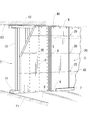
図1乃至図3は、本発明に係る耐火間仕切壁の構造を示す縦断面図、横断面図及び斜視図である。
【0017】
本実施例において、間仕切壁1は、鉄筋コンクリート床スラブF1上に施工される。間仕切壁1の下端部は、床スラブF1に固定され、間仕切壁1の上端部は、上階の鉄筋コンクリート床スラブF2に固定される。間仕切壁1の軸組は、鋼製スタッド10、床ランナ11及び天井ランナ12により構成される。スタッド10は、軽量鉄骨製のチャンネル型部材からなり、床ランナ11及び天井ランナ12は、軽量溝型鋼からなる。ランナ11、12は、アンカーボルト等の係止具13によって床スラブF1、F2に夫々固定され、スタッド10の下端部及び上端部が、床ランナ11及び天井ランナ12に夫々係止する。スタッド10は、300〜600mm程度の寸法に設定された所定間隔(例えば、455mm間隔)を隔てて壁芯方向に整列し、床スラブF1、F2の間に垂直に立設する。
【0018】
下貼ボード2が、ビス8及び/又は接着剤等によってスタッド10の両側に取付けられ、工場加工により予め表面仕上4を施した化粧ボード3が、ビス9又はステープル(図示せず)によって下地ボード2の表面に固定される。下貼ボード2として、石膏ボード又は石膏板を好適に使用し、化粧ボード3として、化粧石膏ボード、化粧セメント板、化粧スレート、化粧珪酸カルシウム板等の不燃性の内装化粧板を好適に使用し得る。下貼ボード2として、硬質石膏板(比重約1.25)又はガラス繊維補強石膏板(比重約1.0)を使用しても良い。化粧ボード3の仕上表面4が室内側に面し、仕上表面4は、クロス又は塗装等の内装仕上工事を施すことなく、室内側の仕上壁面を形成する。
【0019】
図1に示す如く、床仕上材6が、床スラブF1上に施工され、巾木7が、間仕切壁1の下端縁に取付けられる。巾木7は、化粧ボード3の下端部に配置されたビス9のビス頭を室内側から被覆し、下端部のビス頭は、巾木7によって隠蔽される。巾木7として、汎用の既製巾木、例えば、ビニール巾木等を使用し得る。
【0020】
天井軽鉄下地Cが、上階床スラブF2に懸吊され、天井仕上材5が、天井軽鉄下地Cに取付けられる。天井仕上材5は、天井廻り縁等の見切り縁(図示せず)を介して化粧ボード3の室内側壁面に連接する。廻り縁として、樹脂又は金属製の既製見切り縁又はジョイナーや、木材の加工品を使用し得る。所望により、天井廻り縁部分に目透かし目地を形成し、或いは、コーキング材又はシーリング材を充填したシール材充填目地を形成しても良い。
【0021】
図3に示す如く、下地ボード2は、横張り方向に施工され、化粧ボード3は、縦張り方向に施工される。上下の下地ボード2は、横目地20において互いに突付けられる。複数の横目地20は、突付け目地形態の継目として水平且つ平行に延びる。他方、化粧ボード3の縦目地30は、目透かし目地の形態に施工され、縦目地30の幅は、約3〜10mm程度の寸法、例えば5mmに設定される。
【0022】
このように下地ボード2及び化粧ボード3を直交方向に施工した場合、ボード張り作業の施工誤差を修正し得るばかりでなく、強度、遮音性能、熱膨張・収縮性及び強度等の諸物性に関する各ボード2、3の指向性ないし方向性の相違により、壁面全体の諸物性を全体的に平準化することができ、この結果として、壁面全体の品質を向上することができる。しかしながら、本発明者等が、この状態(即ち、耐火目地材を取付ける前の状態)の間仕切壁に関して耐火試験を実施した結果、横目地20及び縦目地30の目地交差部25には、熱風の吹抜けが生じる可能性が高く、これが耐火上の弱点となることが判明した。即ち、下地ボード2及び化粧ボード3を直交方向に配向することは、施工性、あるいは、間仕切壁の各種性能を向上する上で有利である反面、目地交差部25には、各ボード2、3の熱膨張時又は熱変形時に微細な隙間又は小孔が生じ易く、このような隙間又は小孔は、間仕切壁1の片側の高温雰囲気を壁体の反対側に漏出又は噴出させる原因となり易い。
【0023】
このため、本実施例の間仕切壁1は、図2に示す如く、縦目地30内に配設した耐火目地材40を備える。
図4は、耐火目地材40の構造を示す間仕切壁1の部分拡大断面図である。
【0024】
耐火目地材40は、厚さ0.3〜0.5mmの防錆鋼板又は化粧鋼板、例えば、厚さ0.3mmの亜鉛鉄板の曲げ成形品からなり、全長に亘って均一なハット型(帽子型)の断面形状を有する。耐火目地材40は、縦目地30の左右に延びる一対の脚部41と、縦目地30内に位置する隆起部42とを備える。耐火目地材40の左右の脚部41は、下地ボード2及び化粧ボード3の間に介挿され、ボード2、3の間に挟持される。実際の施工において、耐火目地材40は、下地ボード2上に化粧ボード3を上張りする際に縦目地30の部分に位置決めされ、化粧ボード3の縁部により下地ボード2上に押付けられる。所望により、接着材又は接着剤を脚部41に塗布し、脚部41をボード2、3に接着しても良い。中央に位置する隆起部42は、ボード2の表面から僅かに隆起するが、目地底を構成する隆起部42の表面は、化粧ボード3の表層から依然として距離を隔て、目地内に引っ込んでおり、従って、縦目地30の目透かし目地形態は、耐火目地材40の配設によってその意匠性を損なうことはない。同時に、隆起部42が表面仕上4から引っ込むことにより、隆起部42の室内側に室内側垂直通路45が形成され、亜鉛鉄板が隆起することにより、隆起部42と下地ボード2との間に内部垂直通路46が形成される。
【0025】
図1に示す如く、長尺の耐火目地材40は、床スラブF1から上階床スラブF2まで連続し、間仕切壁1の全高に亘って延在する。横目地20と縦目地30との交差部25は、耐火目地材40により閉塞し、室内側から実質的に完全に隠蔽される。従って、一方の側の室に火災が発生して間仕切壁1が加熱されたとしても、火災時の熱気は、目地交差部25から他方の側の室に漏出することなく、間仕切壁1の裏面温度(火災発生室とは反対側の室の壁面温度)に影響しない。従って、上記耐火目地材40を目地交差部25に設けることにより、目地交差部25の近傍に局所的な高温域が形成されるのを防止することができる。
【0026】
実際、本発明者は、耐火目地材40を備えた上記構成の間仕切壁1に関し、耐火試験を繰返し実施したが、耐火目地材40を備えた間仕切壁1にあっては、縦目地30の近傍の雰囲気温度は、縦目地30の全長に亘って200℃(室温+180℃)未満の値を示しており、この結果、熱気の漏出による局所的高温域の形成は、耐火目地材40の配設により確実に防止し得ることが確認された。
【0027】
また、上述の室内側垂直通路45には、壁面温度上昇時に上昇気流が発生し、上昇気流は、縦目地部分の温度上昇を上昇気流の熱搬送・放熱作用により抑制するよう機能する。このため、上記耐火目地材40の構造は、縦目地30近傍の温度上昇を抑制する上で有利に作用すると考えられる。同様に、内部垂直通路46も又、縦目地部分の温度上昇を熱搬送・放熱作用により抑制する上昇気流を下地ボード2と隆起部42との間に生起する。
【0028】
図5乃至図7は、耐火目地材40の変形例を示す間仕切壁の部分拡大断面図である。
図5に示す耐火目地材50は、厚さ0.3〜0.5mmの防錆鋼板又は化粧鋼板、例えば、厚さ0.3mmの亜鉛鉄板の帯板からなる。耐火目地材50は、全長に亘って均一且つ平坦な断面形状を有し、耐火目地材50の縁部領域51は、下地ボード2及び化粧ボード3の間に介挿され、ボード2、3の間に挟持される。耐火目地材50の中央帯域52は、目地交差部25の目地底を閉塞し、目地交差部25における熱気の流通を阻止する。
【0029】
図6に示す耐火目地材60は、厚さ0.3〜0.5mmの防錆鋼板又は化粧鋼板、例えば、厚さ0.3mmの亜鉛鉄板の帯板と、帯板の中央帯域62に一体的に固定した方形断面の不燃材63とから構成される。不燃材63は、石膏ボード、石膏板又は珪酸カルシウム板の裁断片からなり、帯板と同一の全長を有する長尺の有形部材として、耐熱性接着材又は接着剤によって中央帯域62の片面に固定される。全体的にハット型に形成された耐火目地材60は、左右の脚部61を下地ボード2及び化粧ボード3の間に介挿した状態で縦目地30内に保持される。所望により、接着材又は接着剤を脚部61に塗布し、耐火目地材60をボード2、3に接着しても良い。
【0030】
図7に示す耐火目地材70は、図6に示す耐火目地材60と同じく、帯板の中央帯域72に不燃材73を一体的に取付けた構造を有する。しかしながら、耐火目地材70の脚部71は、不燃材73の一方の側にのみ形成される。耐火目地材70は、縦目地30の片側の下地ボード2及び化粧ボード3の間に脚部71を介挿した状態で縦目地30内に保持される。
【0031】
なお、図5乃至図7に示す耐火目地材50、60、70において、所望により、接着材又は接着剤を縁部領域51又は脚部61、71に塗布し、耐火目地材50、60、70をボード2、3に接着しても良い。
以上、本発明の好適な実施例について詳細に説明したが、本発明は上記実施例に限定されるものではなく、特許請求の範囲に記載された本発明の範囲内で種々の変形又は変更が可能であり、該変形例又は変更例も又、本発明の範囲内に含まれるものであることは、いうまでもない。
【0032】
例えば、下地ボード及び化粧ボードの素材は、耐火間仕切壁の面材として使用可能な耐火性及び不燃性を備えたものであれば良く、上述した石膏ボード、石膏板、珪酸カルシウム板等に限定されるものではない。
【0033】
また、前述の実施例は、壁芯位置にスタッドを配置したシングル配列の間仕切壁に関するものであるが、壁芯の両側に2列にスタッドを整列配置したダブル配列の間仕切壁に本発明の構成を採用しても良い。
【0034】
【発明の効果】
以上説明した如く、本発明の上記構成によれば、軸組部材に下地面材を横張りに施工し且つ内装化粧板を下地面材の上に縦張りに施工した構造の耐火間仕切壁において、下地面材の横目地と、内装化粧板の縦目地との目地交差部に生じ得る局所的な耐火性能の劣化を防止し、火災時における熱気の漏出により局部的な高温域が縦目地近傍に発生するのを防止することができる。
【図面の簡単な説明】
【図1】本発明の実施例に係る耐火間仕切壁の縦断面図である。
【図2】図1の II-II線における耐火間仕切壁の断面図である。
【図3】図1及び図2に示す耐火間仕切壁の部分破断斜視図である。
【図4】図1乃至図3に示す耐火間仕切壁の目地構造を示す部分拡大断面図である。
【図5】耐火目地材の変形例を示す間仕切壁の部分拡大断面図である。
【図6】耐火目地材の他の変形例を示す間仕切壁の部分拡大断面図である。
【図7】耐火目地材の更に他の変形例を示す間仕切壁の部分拡大断面図である。
【図8】耐火目地材を備えていない耐火間仕切壁の構造を示す間仕切壁の縦断面図である。
【符号の説明】
1 間仕切壁
2 下貼ボード
3 化粧ボード
4 仕上表面
10 鋼製スタッド
20 横目地
25 目地交差部
30 縦目地
40、50、60、70 耐火目地材[0001]
[Industrial application fields]
The present invention relates to a joint structure of a fireproof partition wall, and more particularly, to a fireproof joint material inserted at a joint intersection to improve the fireproof performance of the fireproof partition wall.
[0002]
[Prior art]
Walls of buildings are based on collective or city-planned conditions such as building use and scale, such as the use and scale of the building, or the site and layout of the building, strength, fireproof performance, seismic performance As for various performances, etc., it is subject to various regulations under the Building Standard Law. In addition, each public organization, such as the Ministry of Land, Infrastructure, Transport and Tourism, Housing Finance Corporation, Housing and Urban Development Corporation, has established its own standards for various performances of walls according to standard specifications or special specifications. For institutional buildings, more detailed heat insulation standards, sound insulation standards, fireproof standards, earthquake resistance standards, etc. may be applied depending on the nature and type of the wall.
[0003]
In particular, with regard to fireproof performance of building walls, interior restrictions and fireproof performance are strictly stipulated in the Building Standards Law, so the structure and constituent materials of the walls are limited by the interior restrictions specified in the Building Standards Law. And must comply with fireproof performance. For example, the Building Standards Act not only prescribes the structure of the entire building as a fireproof building or a simple fireproof building based on the use, scale, and area designation of the building, but also the use, scale, and prevention of fire spread of the building. From the viewpoints of evacuation, smoke removal, fire extinguishing, etc., fireproof performance is regulated with respect to each internal structure of the building, such as interior materials, inner wall structures, joinery structures, and pipe penetrations. Here, under the current Building Standards Law, building interior materials are classified into predetermined non-combustible grades (non-combustible material, semi-incombustible material and flame retardant material) with respect to non-combustible performance, and the building wall is The fireproof performance is classified into predetermined structural types (fireproof structure, semi-fireproof structure, fireproof structure, semifireproof structure, etc.).
[0004]
In addition, from the viewpoint of reducing the weight of the building, a dry fireproof partition wall having a structure in which a fireproof board material such as a gypsum board or a calcium silicate board is attached to both sides of a lightweight steel stud is provided as a fireproof compartment and a smoke exhaust compartment. Or it is used as a fire protection compartment wall such as a pit compartment.
[0005]
FIG. 8 is a longitudinal sectional view showing the structure of the fireproof partition wall of the dry construction method. The partition wall W shown in FIG. 8 lays a lightweight steel stud S vertically between upper and lower floor slabs or beams F1: F2, and a board material B1: B2 such as a gypsum board or a calcium silicate board on both sides of the stud S. Is a double-tensioned structure. In this type of partition wall W, an interior finishing material such as an interior decorative board, cloth, or paint is further laminated on the top board B2, and the interior finishing material forms an interior finishing surface B3 facing the indoor side.
[0006]
[Problems to be solved by the invention]
In such a fireproof partition wall, the construction mode in which the lower board B1 is installed horizontally and the upper board B2 is installed vertically is construction accuracy, sound insulation, fire resistance, thermal expansion and contraction, strength, This is desirable from the viewpoint of directivity. For this reason, a horizontal horizontal joint is formed on the construction surface of the lower pasting board B1, and a vertical vertical joint is formed on the construction surface of the upper pasting board B2.
[0007]
Here, the present inventor directly uses the interior decorative board whose surface finish is factory processed as the upper adhesive board, and attaches the wall surface of the two-layer structure composed of the lower adhesive board and the inner decorative board to both sides of the stud S. We have been researching the structural fireproof partition. According to such a fireproof partition wall, it is possible to reduce the construction cost and the construction period compared with the conventional fireproof partition wall having a three-layer structure of the board materials B1 and B2 and the interior finishing material B3.
[0008]
However, as a result of the repeated execution of the fire resistance test by the present inventors regarding the partition wall of this structure, fire resistance performance is provided at the portion where the horizontal joint of the underlaying board (base material) intersects with the vertical joint of the interior decorative board. It became clear that the phenomenon which deteriorates locally tends to occur.
[0009]
The present invention has been made in view of such circumstances, and the object of the present invention is to apply a base surface material horizontally to a frame member and to apply an interior decorative board vertically to a base material. In the fire-resistant partition wall with the above structure, local deterioration of the fire resistance that can occur at the joints between the horizontal joints of the base material and the vertical joints of the interior decorative panel is prevented, and localized due to the leakage of hot air in the event of a fire It is to prevent a high temperature region from occurring near the vertical joint.
[0010]
[Means and Actions for Solving the Problems]
To achieve the above object, the present invention comprises a vertical steel stud extending between upper and lower horizontal refractory compartments and aligned along a wall core, and oriented in a transverse direction and secured to said stud. In the fireproof joint structure in the fireproof partition wall composed of the base surface material and the interior decorative board fixed in the longitudinal direction on the base surface material,
The horizontal joint of the base surface material has an intersection with the vertical joint of the interior decorative board,
The vertical joint is formed in the form of an open joint on the interior side wall surface of the interior decorative board, and a fireproof joint material is disposed in the joint of the vertical joint,
The refractory joint member includes an insertion portion which is interposed between the lower ground material with an edge of said interior decorative panel, and eye underground portion for closing and concealing the eye underground of the longitudinal joint the intersection Prepared,
The fireproof joint material is formed of a metal plate molded member having left and right leg portions and a raised portion between the leg portions, and the leg portions constitute the insertion portion. Provide wall fireproof joint structure .
The present invention also includes a vertical steel stud extending between upper and lower horizontal refractory compartments and aligned along the wall core, a base material oriented in a transverse direction and fixed to the stud, In the fireproof joint structure in the fireproof partition wall composed of an interior decorative board fixed in the vertical direction on the lower ground material,
The horizontal joint of the base surface material has an intersection with the vertical joint of the interior decorative board,
The vertical joint is formed in the form of an open joint on the interior side wall surface of the interior decorative board, and a fireproof joint material is disposed in the joint of the vertical joint,
The fireproof joint material includes an insertion portion interposed between an edge portion of the interior decorative board and the base surface material, and a joint bottom portion that conceals the joint bottom of the vertical joint and closes the intersecting portion. Prepared,
The fireproof joint material has a structure in which a nonflammable material having a long and square cross section is integrally fixed on a metal plate in the form of a strip, and the edges on both sides of the metal plate constitute the insertion portion. A fireproof joint structure of a fireproof partition wall characterized by the above is provided.
[0011]
According to the above configuration of the present invention, the wall surface of the fireproof partition wall is configured by the base surface material and the interior decorative board oriented in the orthogonal direction, and the horizontal joint of the base surface material intersects with the vertical joint of the interior decorative board. To do. The vertical joint of the interior decorative board has a form of a watermark joint, and a fire resistance weakness that is locally inferior in fire resistance can occur at the joint intersection. However, the refractory joint material disposed at least at the joint joints closes the joint joint bottom of the vertical joints, prevents the ejection or outflow of hot air from the joint joints, and is locally in the vicinity of the vertical joints and in the vertical joints. Prevent high temperature areas from occurring.
[0012]
According to the fireproof partition wall having such a fireproof joint material, when a fire occurs in one of the chambers, the temperature of the entire rear surface of the partition wall rises relatively on average, and a local high temperature region is generated. Therefore, the partition wall exhibits the desired fire resistance performance in combination with the specific action (thermal expansion / contraction and leveling of strength, etc.) due to the orientation of the base surface material and the interior decorative board in the orthogonal direction. To do.
[0013]
DETAILED DESCRIPTION OF THE INVENTION
[0014]
According to another embodiment of the present invention, the fireproof joint material has a structure in which a nonflammable material having a long and square cross section is integrally fixed on the metal plate. The non-combustible material is made of cut pieces such as gypsum board, gypsum plate, calcium silicate plate, wood-based non-combustible material, metal material, rock wool and the like. The edge part of a metal plate comprises the said insertion part, and a noncombustible material is corresponded to the said protruding part.
[0015]
The raised portion or the non-combustible material not only functions as a positioning means when inserting the refractory joint material into the vertical joint, but also functions to improve the fire resistance performance of the joint joint bottom of the vertical joint. Preferably, the height or thickness of the raised portion or the non-combustible material is set to be thinner than the depth of the vertical joint, and the vertical joint of the interior decorative board maintains the shape of the open joint that is recessed from the surface of the decorative board. In this way, by maintaining the vertical joint shape of the vertical joint and forming the indoor vertical passage in the vertical joint, a vertical passage capable of generating an updraft is formed in the vertical joint portion. In the vertical passage, when a fire occurs in the room on the opposite side of the partition wall, a rising air flow is generated due to the temperature rise of the wall surface, and the temperature rise in the vertical joint is suppressed by the heat transfer and heat dissipation action of the rising air flow Is done. Such a region may be further formed as an internal vertical passage between the fireproof joint material and the base surface material.
[0016]
【Example】
Hereinafter, with reference to an accompanying drawing, the example of the fireproof partition wall concerning the present invention is described in detail.
1 to 3 are a longitudinal sectional view, a transverse sectional view, and a perspective view showing a structure of a fireproof partition wall according to the present invention.
[0017]
In this embodiment, the
[0018]
The
[0019]
As shown in FIG. 1, the
[0020]
The ceiling light iron base C is suspended from the upper floor slab F2, and the
[0021]
As shown in FIG. 3, the
[0022]
In this way, when the
[0023]
For this reason, the
FIG. 4 is a partially enlarged sectional view of the
[0024]
The fireproof
[0025]
As shown in FIG. 1, the long fireproof
[0026]
Actually, the inventor repeatedly performed the fireproof test on the
[0027]
Further, in the indoor
[0028]
5 to 7 are partial enlarged cross-sectional views of partition walls showing modifications of the refractory
The fireproof
[0029]
The fireproof
[0030]
The fireproof
[0031]
In addition, in the fireproof
The preferred embodiments of the present invention have been described in detail above, but the present invention is not limited to the above-described embodiments, and various modifications or changes can be made within the scope of the present invention described in the claims. Needless to say, such modifications and variations are also included in the scope of the present invention.
[0032]
For example, the material for the base board and the decorative board is not limited to the above-mentioned gypsum board, gypsum board, calcium silicate board, etc., as long as it has fire resistance and non-combustibility that can be used as the face material of the fireproof partition wall. It is not something.
[0033]
The above-mentioned embodiment relates to a single arrangement partition wall in which studs are arranged at the wall core position, but the double arrangement partition wall in which studs are arranged in two rows on both sides of the wall core is configured according to the present invention. May be adopted.
[0034]
【The invention's effect】
As described above, according to the above-described configuration of the present invention, in the fireproof partition wall having a structure in which the base member is applied horizontally to the frame member and the interior decorative board is applied vertically to the base member, Prevents local deterioration of the fire resistance that can occur at the joints between the horizontal joints of the lower ground material and the vertical joints of the interior decorative board, and the local high temperature area is near the vertical joints due to the leakage of hot air during a fire. It can be prevented from occurring.
[Brief description of the drawings]
FIG. 1 is a longitudinal sectional view of a fireproof partition wall according to an embodiment of the present invention.
FIG. 2 is a cross-sectional view of a fireproof partition wall taken along line II-II in FIG.
3 is a partially broken perspective view of the fireproof partition wall shown in FIGS. 1 and 2. FIG.
4 is a partially enlarged cross-sectional view showing a joint structure of a fireproof partition wall shown in FIGS. 1 to 3; FIG.
FIG. 5 is a partially enlarged sectional view of a partition wall showing a modified example of the fireproof joint material.
FIG. 6 is a partially enlarged cross-sectional view of a partition wall showing another modification of the fireproof joint material.
FIG. 7 is a partially enlarged cross-sectional view of a partition wall showing still another modified example of the fireproof joint material.
FIG. 8 is a longitudinal sectional view of a partition wall showing a structure of a fireproof partition wall not provided with a fireproof joint material.
[Explanation of symbols]
DESCRIPTION OF
Claims (6)
前記下地面材の横目地は、前記内装化粧板の縦目地との交差部を有し、
前記縦目地は、前記内装化粧板の室内側壁面に目透かし目地の形態に形成され、該縦目地の目地内には、耐火目地材が配置され、
該耐火目地材は、前記内装化粧板の縁部と前記下地面材との間に介挿される挿入部と、前記縦目地の目地底を隠蔽して前記交差部を閉塞する目地底部分とを備え、
前記耐火目地材は、左右の脚部と、該脚部の間の隆起部とを備えた金属板の成形部材からなり、前記脚部は、前記挿入部を構成することを特徴とする耐火間仕切壁の耐火目地構造。 A vertical steel stud extending between upper and lower horizontal refractory compartments and aligned along the wall core; a base material oriented in a transverse direction and fixed to the stud; and In the fireproof joint structure in the fireproof partition wall composed of the interior decorative board fixed in the vertical direction to
The horizontal joint of the base surface material has an intersection with the vertical joint of the interior decorative board,
The vertical joint is formed in the form of an open joint on the interior side wall surface of the interior decorative board, and a fireproof joint material is disposed in the joint of the vertical joint,
The refractory joint member includes an insertion portion which is interposed between the lower ground material with an edge of said interior decorative panel, and eye underground portion for closing and concealing the eye underground of the longitudinal joint the intersection Prepared,
The fireproof joint material is formed of a metal plate molded member having left and right leg portions and a raised portion between the leg portions, and the leg portions constitute the insertion portion. Wall fireproof joint structure .
前記下地面材の横目地は、前記内装化粧板の縦目地との交差部を有し、 The horizontal joint of the base surface material has an intersection with the vertical joint of the interior decorative board,
前記縦目地は、前記内装化粧板の室内側壁面に目透かし目地の形態に形成され、該縦目地の目地内には、耐火目地材が配置され、 The vertical joint is formed in the form of a watermark joint on the interior side wall surface of the interior decorative board, and a fireproof joint material is disposed in the joint of the vertical joint,
該耐火目地材は、前記内装化粧板の縁部と前記下地面材との間に介挿される挿入部と、前記縦目地の目地底を隠蔽して前記交差部を閉塞する目地底部分とを備え、 The fireproof joint material includes an insertion portion interposed between an edge portion of the interior decorative board and the base surface material, and a joint base portion that hides the joint joint of the vertical joint and closes the intersecting portion. Prepared,
前記耐火目地材は、帯板形態の金属板上に長尺且つ方形断面の不燃材を一体的に固定した構造を有し、該金属板の両側の縁部は、前記挿入部を構成することを特徴とする耐火間仕切壁の耐火目地構造。 The fireproof joint material has a structure in which a nonflammable material having a long and square cross section is integrally fixed on a metal plate in the form of a strip, and the edges on both sides of the metal plate constitute the insertion portion. Fireproof joint structure of fireproof partition wall characterized by
Priority Applications (1)
| Application Number | Priority Date | Filing Date | Title |
|---|---|---|---|
| JP2001113302A JP4021156B2 (en) | 2001-04-11 | 2001-04-11 | Fireproof joint structure of fireproof partition walls |
Applications Claiming Priority (1)
| Application Number | Priority Date | Filing Date | Title |
|---|---|---|---|
| JP2001113302A JP4021156B2 (en) | 2001-04-11 | 2001-04-11 | Fireproof joint structure of fireproof partition walls |
Publications (2)
| Publication Number | Publication Date |
|---|---|
| JP2002309691A JP2002309691A (en) | 2002-10-23 |
| JP4021156B2 true JP4021156B2 (en) | 2007-12-12 |
Family
ID=18964546
Family Applications (1)
| Application Number | Title | Priority Date | Filing Date |
|---|---|---|---|
| JP2001113302A Expired - Lifetime JP4021156B2 (en) | 2001-04-11 | 2001-04-11 | Fireproof joint structure of fireproof partition walls |
Country Status (1)
| Country | Link |
|---|---|
| JP (1) | JP4021156B2 (en) |
Cited By (1)
| Publication number | Priority date | Publication date | Assignee | Title |
|---|---|---|---|---|
| JP2017186891A (en) * | 2010-12-20 | 2017-10-12 | 吉野石膏株式会社 | Joint structure of light fireproof partition wall and construction method thereof |
Families Citing this family (16)
| Publication number | Priority date | Publication date | Assignee | Title |
|---|---|---|---|---|
| US10364572B2 (en) | 2014-08-30 | 2019-07-30 | Innovative Building Technologies, Llc | Prefabricated wall panel for utility installation |
| WO2016032538A1 (en) | 2014-08-30 | 2016-03-03 | Innovative Building Technologies, Llc | Diaphragm to lateral support coupling in a structure |
| CA2962552C (en) | 2014-08-30 | 2019-08-13 | Innovative Building Technologies, Llc | Floor and ceiling panel for use in buildings |
| CA3015815C (en) | 2016-03-07 | 2021-01-05 | Innovative Building Technologies, Llc | A pre-assembled wall panel for utility installation |
| US10900224B2 (en) | 2016-03-07 | 2021-01-26 | Innovative Building Technologies, Llc | Prefabricated demising wall with external conduit engagement features |
| JP6936240B2 (en) | 2016-03-07 | 2021-09-15 | イノベイティブ ビルディング テクノロジーズ,エルエルシー | Prefabricated wall panels including waterproof assembly and waterproof assembly |
| KR101973665B1 (en) * | 2016-04-22 | 2019-04-29 | 주식회사 광스틸 | Fireproof partition |
| KR102084652B1 (en) * | 2017-01-18 | 2020-03-04 | 주식회사 광스틸 | Fireproof partition |
| US10724228B2 (en) | 2017-05-12 | 2020-07-28 | Innovative Building Technologies, Llc | Building assemblies and methods for constructing a building using pre-assembled floor-ceiling panels and walls |
| US11098475B2 (en) | 2017-05-12 | 2021-08-24 | Innovative Building Technologies, Llc | Building system with a diaphragm provided by pre-fabricated floor panels |
| JP6687058B2 (en) * | 2018-05-10 | 2020-04-22 | 積水ハウス株式会社 | Wall structure |
| AU2020436409B2 (en) | 2020-03-19 | 2023-11-23 | Yoshino Gypsum Co., Ltd. | Connection structure between partition wall and floor and construction method therefor |
| CN112709477A (en) * | 2020-12-24 | 2021-04-27 | 中车资阳机车有限公司 | Electric automobile parking stall is with fire prevention division wall |
| RU207115U1 (en) * | 2021-03-24 | 2021-10-13 | Открытое акционерное общество "Объединенные электротехнические заводы" | MODULAR STRUCTURE |
| JPWO2023149306A1 (en) * | 2022-02-03 | 2023-08-10 | ||
| WO2023233715A1 (en) * | 2022-05-31 | 2023-12-07 | 吉野石膏株式会社 | Building wall |
-
2001
- 2001-04-11 JP JP2001113302A patent/JP4021156B2/en not_active Expired - Lifetime
Cited By (1)
| Publication number | Priority date | Publication date | Assignee | Title |
|---|---|---|---|---|
| JP2017186891A (en) * | 2010-12-20 | 2017-10-12 | 吉野石膏株式会社 | Joint structure of light fireproof partition wall and construction method thereof |
Also Published As
| Publication number | Publication date |
|---|---|
| JP2002309691A (en) | 2002-10-23 |
Similar Documents
| Publication | Publication Date | Title |
|---|---|---|
| JP4021156B2 (en) | Fireproof joint structure of fireproof partition walls | |
| JP4049564B2 (en) | Fireproof partition wall and its construction method | |
| US6119411A (en) | Enclosure which is fire-resistive for a predetermined period of time | |
| KR100735576B1 (en) | The insulation panel with reinforcement and construct method of panel thereof | |
| JP6163283B2 (en) | Joint structure and construction method of lightweight fireproof partition wall | |
| JP6463321B2 (en) | Panel unit and curtain wall provided with the same | |
| JP5663119B2 (en) | Open joint structure of partition wall and its construction method | |
| KR101126353B1 (en) | Fire door and manufacturing method thereof | |
| KR100604411B1 (en) | The construction method of prefabricated partition with cavity wall using composition panels | |
| JP2008240355A (en) | Structure and method for connecting column or beam to fireproof partition wall | |
| JP2014101751A (en) | Fireproof compartment method | |
| JP4700215B2 (en) | Fire protection wall | |
| KR200332657Y1 (en) | partition panel and assembling structure of it | |
| US3872640A (en) | Prefabricated structural unit body and structures thereof | |
| KR100555129B1 (en) | partition panel and assembling structure of it | |
| JP4159091B2 (en) | Partition wall structure | |
| JP2021008712A (en) | Fire-resistant coating structure for wall composed of heat insulating panel, and heat insulating panel fire-resistant coating body | |
| JP2003064813A (en) | Dry partition wall structure | |
| JP2019112795A (en) | Fire-resistance coating structure of penetration part | |
| JP2002180575A (en) | Exterior wall structure, heat insulating material and building | |
| JP7488646B2 (en) | Functional material construction | |
| JPH0712626Y2 (en) | Fire door structure | |
| JP2003064804A (en) | Join structure of fire-resisting partition wall and column and beam and join method | |
| JP3118550U (en) | A mini-kura with an outer insulation system that is suitable for preventing condensation due to the double structure of "non-combustible insulation" and "concrete". | |
| JP2024088101A (en) | Joiner |
Legal Events
| Date | Code | Title | Description |
|---|---|---|---|
| A621 | Written request for application examination |
Free format text: JAPANESE INTERMEDIATE CODE: A621 Effective date: 20050705 |
|
| A977 | Report on retrieval |
Free format text: JAPANESE INTERMEDIATE CODE: A971007 Effective date: 20070601 |
|
| A131 | Notification of reasons for refusal |
Free format text: JAPANESE INTERMEDIATE CODE: A131 Effective date: 20070608 |
|
| A521 | Written amendment |
Free format text: JAPANESE INTERMEDIATE CODE: A523 Effective date: 20070807 |
|
| A521 | Written amendment |
Free format text: JAPANESE INTERMEDIATE CODE: A821 Effective date: 20070808 |
|
| TRDD | Decision of grant or rejection written | ||
| A01 | Written decision to grant a patent or to grant a registration (utility model) |
Free format text: JAPANESE INTERMEDIATE CODE: A01 Effective date: 20070918 |
|
| A61 | First payment of annual fees (during grant procedure) |
Free format text: JAPANESE INTERMEDIATE CODE: A61 Effective date: 20070926 |
|
| FPAY | Renewal fee payment (event date is renewal date of database) |
Free format text: PAYMENT UNTIL: 20101005 Year of fee payment: 3 |
|
| R150 | Certificate of patent or registration of utility model |
Ref document number: 4021156 Country of ref document: JP Free format text: JAPANESE INTERMEDIATE CODE: R150 Free format text: JAPANESE INTERMEDIATE CODE: R150 |
|
| FPAY | Renewal fee payment (event date is renewal date of database) |
Free format text: PAYMENT UNTIL: 20131005 Year of fee payment: 6 |
|
| R250 | Receipt of annual fees |
Free format text: JAPANESE INTERMEDIATE CODE: R250 |
|
| R250 | Receipt of annual fees |
Free format text: JAPANESE INTERMEDIATE CODE: R250 |
|
| R250 | Receipt of annual fees |
Free format text: JAPANESE INTERMEDIATE CODE: R250 |
|
| R250 | Receipt of annual fees |
Free format text: JAPANESE INTERMEDIATE CODE: R250 |
|
| EXPY | Cancellation because of completion of term |