JP2005121501A - タンデム型回転検出装置 - Google Patents
タンデム型回転検出装置 Download PDFInfo
- Publication number
- JP2005121501A JP2005121501A JP2003357360A JP2003357360A JP2005121501A JP 2005121501 A JP2005121501 A JP 2005121501A JP 2003357360 A JP2003357360 A JP 2003357360A JP 2003357360 A JP2003357360 A JP 2003357360A JP 2005121501 A JP2005121501 A JP 2005121501A
- Authority
- JP
- Japan
- Prior art keywords
- rotation
- detection mechanism
- rotation angle
- core portion
- housing
- Prior art date
- Legal status (The legal status is an assumption and is not a legal conclusion. Google has not performed a legal analysis and makes no representation as to the accuracy of the status listed.)
- Pending
Links
Images


Classifications
-
- B—PERFORMING OPERATIONS; TRANSPORTING
- B62—LAND VEHICLES FOR TRAVELLING OTHERWISE THAN ON RAILS
- B62D—MOTOR VEHICLES; TRAILERS
- B62D6/00—Arrangements for automatically controlling steering depending on driving conditions sensed and responded to, e.g. control circuits
- B62D6/08—Arrangements for automatically controlling steering depending on driving conditions sensed and responded to, e.g. control circuits responsive only to driver input torque
- B62D6/10—Arrangements for automatically controlling steering depending on driving conditions sensed and responded to, e.g. control circuits responsive only to driver input torque characterised by means for sensing or determining torque
-
- G—PHYSICS
- G01—MEASURING; TESTING
- G01L—MEASURING FORCE, STRESS, TORQUE, WORK, MECHANICAL POWER, MECHANICAL EFFICIENCY, OR FLUID PRESSURE
- G01L3/00—Measuring torque, work, mechanical power, or mechanical efficiency, in general
- G01L3/02—Rotary-transmission dynamometers
- G01L3/04—Rotary-transmission dynamometers wherein the torque-transmitting element comprises a torsionally-flexible shaft
- G01L3/10—Rotary-transmission dynamometers wherein the torque-transmitting element comprises a torsionally-flexible shaft involving electric or magnetic means for indicating
- G01L3/101—Rotary-transmission dynamometers wherein the torque-transmitting element comprises a torsionally-flexible shaft involving electric or magnetic means for indicating involving magnetic or electromagnetic means
- G01L3/105—Rotary-transmission dynamometers wherein the torque-transmitting element comprises a torsionally-flexible shaft involving electric or magnetic means for indicating involving magnetic or electromagnetic means involving inductive means
-
- G—PHYSICS
- G01—MEASURING; TESTING
- G01L—MEASURING FORCE, STRESS, TORQUE, WORK, MECHANICAL POWER, MECHANICAL EFFICIENCY, OR FLUID PRESSURE
- G01L3/00—Measuring torque, work, mechanical power, or mechanical efficiency, in general
- G01L3/02—Rotary-transmission dynamometers
- G01L3/04—Rotary-transmission dynamometers wherein the torque-transmitting element comprises a torsionally-flexible shaft
- G01L3/10—Rotary-transmission dynamometers wherein the torque-transmitting element comprises a torsionally-flexible shaft involving electric or magnetic means for indicating
- G01L3/109—Rotary-transmission dynamometers wherein the torque-transmitting element comprises a torsionally-flexible shaft involving electric or magnetic means for indicating involving measuring phase difference of two signals or pulse trains
Landscapes
- Physics & Mathematics (AREA)
- General Physics & Mathematics (AREA)
- Engineering & Computer Science (AREA)
- Chemical & Material Sciences (AREA)
- Combustion & Propulsion (AREA)
- Transportation (AREA)
- Mechanical Engineering (AREA)
- Electromagnetism (AREA)
- Measurement Of Length, Angles, Or The Like Using Electric Or Magnetic Means (AREA)
- Transmission And Conversion Of Sensor Element Output (AREA)
Abstract
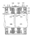
【解決手段】 本発明のタンデム型回転検出装置は、円筒形状のハウジング1の内側に設けられた第1のアウタコア部10Aのコイル11Aに磁束を発生させ、ハウジング1の中心部に挿入された回転軸4Aの回転角を検出する第1の回転検出機構2Aと、第1の回転検出機構2Aに併設され、ハウジング1の内側に設けられた第2のアウタコア部10Bのコイルに磁束を発生させ、ハウジング1の中心部に回転軸4Aと直列に挿入された回転軸4Bの回転角を検出する第2の回転検出機構2Bとを備え、ハウジング1は非磁性材で形成することとした。
【選択図】 図1
Description
4A、4B 回転軸
2A 第1の回転角検出機構
2B 第2の回転角検出機構
5 遮蔽板
10A、50A 第1のアウタコア部
10B、50B 第2のアウタコア部
17a、17b、57a、57b 巻線、
13a、13b、14a、14b、55a、55b、56a、56b 巻線端末
11A、11B、21A、31A、41A、51A、51B コイル
18、58 交流発振器
20A 第1のインナコア部
20B 第2のインナコア部
30A 第1のステータコア部
30B 第2のステータコア部
40A 第1のロータコア部
40B 第2のロータコア部
Claims (4)
- 円筒形状のハウジングの内側に設けられた第1のアウタコア部のコイルに磁束を発生させ、前記ハウジングの中心部に挿入された回転軸の回転角を検出する第1の回転検出機構と、前記第1の回転検出機構に併設され、前記ハウジングの内側に設けられた第2のアウタコア部のコイルに磁束を発生させ、前記回転軸の回転角を検出する第2の回転検出機構とを備え、前記ハウジングは非磁性材で形成することを特徴とするタンデム型回転検出装置。
- 前記第1の回転検出機構と前記第2の回転検出機構との間に遮蔽板を設けることを特徴とする請求項1に記載のタンデム型回転検出装置。
- 前記回転軸は、直列に設置された2本の回転軸とし、前記第1の回転検出機構と前記第1の回転検出機構とにより前記2本の回転軸の回転角度をそれぞれ検出することを特徴とする請求項1または請求項2に記載のタンデム型回転検出装置。
- 前記回転軸は、連続する1本の回転軸とし、前記第1の回転検出機構と前記第1の回転検出機構とにより回転角度差を検出して前記回転軸の回転トルクを検出することを特徴とする請求項1または請求項に記載のタンデム型回転検出装置。
Priority Applications (3)
| Application Number | Priority Date | Filing Date | Title |
|---|---|---|---|
| JP2003357360A JP2005121501A (ja) | 2003-10-17 | 2003-10-17 | タンデム型回転検出装置 |
| US10/950,832 US20050083042A1 (en) | 2003-10-17 | 2004-09-27 | Tandem rotation detector |
| EP04256172A EP1524510A1 (en) | 2003-10-17 | 2004-10-06 | Tandem rotation detector |
Applications Claiming Priority (1)
| Application Number | Priority Date | Filing Date | Title |
|---|---|---|---|
| JP2003357360A JP2005121501A (ja) | 2003-10-17 | 2003-10-17 | タンデム型回転検出装置 |
Publications (2)
| Publication Number | Publication Date |
|---|---|
| JP2005121501A true JP2005121501A (ja) | 2005-05-12 |
| JP2005121501A5 JP2005121501A5 (ja) | 2005-07-28 |
Family
ID=34373618
Family Applications (1)
| Application Number | Title | Priority Date | Filing Date |
|---|---|---|---|
| JP2003357360A Pending JP2005121501A (ja) | 2003-10-17 | 2003-10-17 | タンデム型回転検出装置 |
Country Status (3)
| Country | Link |
|---|---|
| US (1) | US20050083042A1 (ja) |
| EP (1) | EP1524510A1 (ja) |
| JP (1) | JP2005121501A (ja) |
Cited By (4)
| Publication number | Priority date | Publication date | Assignee | Title |
|---|---|---|---|---|
| WO2012108477A1 (ja) * | 2011-02-08 | 2012-08-16 | 株式会社ジェイテクト | トルク検出装置 |
| JP2012163493A (ja) * | 2011-02-08 | 2012-08-30 | Jtekt Corp | トルク検出装置 |
| JP2012163494A (ja) * | 2011-02-08 | 2012-08-30 | Jtekt Corp | トルク検出装置 |
| JP2012163492A (ja) * | 2011-02-08 | 2012-08-30 | Jtekt Corp | トルク検出装置 |
Families Citing this family (1)
| Publication number | Priority date | Publication date | Assignee | Title |
|---|---|---|---|---|
| JP7178668B2 (ja) * | 2018-01-23 | 2022-11-28 | 株式会社アミテック | 誘導型回転検出装置 |
Family Cites Families (4)
| Publication number | Priority date | Publication date | Assignee | Title |
|---|---|---|---|---|
| US4724710A (en) * | 1986-12-22 | 1988-02-16 | General Motors Corporation | Electromagnetic torque sensor for a rotary shaft |
| US5012169A (en) * | 1988-07-20 | 1991-04-30 | Yokogawa Electric Corporation | Motor drive system |
| US5062306A (en) * | 1989-04-20 | 1991-11-05 | Kabushiki Kaisha Toyoda Jidoshokki Seisakusho | Apparatus for detecting torque of rotating shaft |
| JP3831841B2 (ja) * | 2001-09-26 | 2006-10-11 | ミネベア株式会社 | 高精度トルク測定装置 |
-
2003
- 2003-10-17 JP JP2003357360A patent/JP2005121501A/ja active Pending
-
2004
- 2004-09-27 US US10/950,832 patent/US20050083042A1/en not_active Abandoned
- 2004-10-06 EP EP04256172A patent/EP1524510A1/en not_active Withdrawn
Cited By (5)
| Publication number | Priority date | Publication date | Assignee | Title |
|---|---|---|---|---|
| WO2012108477A1 (ja) * | 2011-02-08 | 2012-08-16 | 株式会社ジェイテクト | トルク検出装置 |
| JP2012163493A (ja) * | 2011-02-08 | 2012-08-30 | Jtekt Corp | トルク検出装置 |
| JP2012163494A (ja) * | 2011-02-08 | 2012-08-30 | Jtekt Corp | トルク検出装置 |
| JP2012163492A (ja) * | 2011-02-08 | 2012-08-30 | Jtekt Corp | トルク検出装置 |
| US9057652B2 (en) | 2011-02-08 | 2015-06-16 | Jtekt Corporation | Torque detecting apparatus |
Also Published As
| Publication number | Publication date |
|---|---|
| US20050083042A1 (en) | 2005-04-21 |
| EP1524510A1 (en) | 2005-04-20 |
Similar Documents
| Publication | Publication Date | Title |
|---|---|---|
| KR100913631B1 (ko) | 다회전식 인코더 | |
| US7199691B2 (en) | Flat resolver | |
| EP1918681A1 (en) | Angle detector | |
| TWI476375B (zh) | 磁力式旋轉角檢測器 | |
| KR101555804B1 (ko) | 회전 전기 | |
| JP7076780B2 (ja) | 透磁率の変化を検出するためのコア構造体および歪み検出装置 | |
| JP7076781B2 (ja) | 透磁率の変化を検出するためのコアおよび歪み検出装置 | |
| JP2005164531A (ja) | 磁歪式トルクセンサ | |
| JP5886269B2 (ja) | 回転検出装置およびモータ | |
| JP5133765B2 (ja) | 埋込磁石型モータ及びその設計方法 | |
| JP2005121501A (ja) | タンデム型回転検出装置 | |
| US9441942B2 (en) | Resolver and multiple-rotation detector | |
| JP2005102374A (ja) | ブラシレスレタイプ回転検出器の遮蔽構造 | |
| JP2008029070A (ja) | 角度検出器 | |
| JP3984213B2 (ja) | タンデム型回転検出装置 | |
| WO2020195003A1 (ja) | モータ | |
| CN109687677B (zh) | 旋转变压器定子 | |
| JPS6031005A (ja) | 回転角位置検出器 | |
| WO2022260070A1 (ja) | 運動検出器 | |
| US20220286003A1 (en) | Motor | |
| JP2022187942A (ja) | 運動検出器 | |
| KR20210100896A (ko) | 모터 | |
| JP2023051163A (ja) | 回転検出器 | |
| KR20210078102A (ko) | 모터 | |
| JP2008175553A (ja) | 角度検出器 |
Legal Events
| Date | Code | Title | Description |
|---|---|---|---|
| A521 | Written amendment |
Free format text: JAPANESE INTERMEDIATE CODE: A523 Effective date: 20050208 |
|
| A621 | Written request for application examination |
Free format text: JAPANESE INTERMEDIATE CODE: A621 Effective date: 20050711 |
|
| A977 | Report on retrieval |
Free format text: JAPANESE INTERMEDIATE CODE: A971007 Effective date: 20070302 |
|
| A131 | Notification of reasons for refusal |
Free format text: JAPANESE INTERMEDIATE CODE: A131 Effective date: 20070320 |
|
| A02 | Decision of refusal |
Free format text: JAPANESE INTERMEDIATE CODE: A02 Effective date: 20071002 |