JP2005121501A - Tandem rotation detector - Google Patents
Tandem rotation detector Download PDFInfo
- Publication number
- JP2005121501A JP2005121501A JP2003357360A JP2003357360A JP2005121501A JP 2005121501 A JP2005121501 A JP 2005121501A JP 2003357360 A JP2003357360 A JP 2003357360A JP 2003357360 A JP2003357360 A JP 2003357360A JP 2005121501 A JP2005121501 A JP 2005121501A
- Authority
- JP
- Japan
- Prior art keywords
- rotation
- detection mechanism
- rotation angle
- core portion
- housing
- Prior art date
- Legal status (The legal status is an assumption and is not a legal conclusion. Google has not performed a legal analysis and makes no representation as to the accuracy of the status listed.)
- Pending
Links
Images


Classifications
-
- B—PERFORMING OPERATIONS; TRANSPORTING
- B62—LAND VEHICLES FOR TRAVELLING OTHERWISE THAN ON RAILS
- B62D—MOTOR VEHICLES; TRAILERS
- B62D6/00—Arrangements for automatically controlling steering depending on driving conditions sensed and responded to, e.g. control circuits
- B62D6/08—Arrangements for automatically controlling steering depending on driving conditions sensed and responded to, e.g. control circuits responsive only to driver input torque
- B62D6/10—Arrangements for automatically controlling steering depending on driving conditions sensed and responded to, e.g. control circuits responsive only to driver input torque characterised by means for sensing or determining torque
-
- G—PHYSICS
- G01—MEASURING; TESTING
- G01L—MEASURING FORCE, STRESS, TORQUE, WORK, MECHANICAL POWER, MECHANICAL EFFICIENCY, OR FLUID PRESSURE
- G01L3/00—Measuring torque, work, mechanical power, or mechanical efficiency, in general
- G01L3/02—Rotary-transmission dynamometers
- G01L3/04—Rotary-transmission dynamometers wherein the torque-transmitting element comprises a torsionally-flexible shaft
- G01L3/10—Rotary-transmission dynamometers wherein the torque-transmitting element comprises a torsionally-flexible shaft involving electric or magnetic means for indicating
- G01L3/101—Rotary-transmission dynamometers wherein the torque-transmitting element comprises a torsionally-flexible shaft involving electric or magnetic means for indicating involving magnetic or electromagnetic means
- G01L3/105—Rotary-transmission dynamometers wherein the torque-transmitting element comprises a torsionally-flexible shaft involving electric or magnetic means for indicating involving magnetic or electromagnetic means involving inductive means
-
- G—PHYSICS
- G01—MEASURING; TESTING
- G01L—MEASURING FORCE, STRESS, TORQUE, WORK, MECHANICAL POWER, MECHANICAL EFFICIENCY, OR FLUID PRESSURE
- G01L3/00—Measuring torque, work, mechanical power, or mechanical efficiency, in general
- G01L3/02—Rotary-transmission dynamometers
- G01L3/04—Rotary-transmission dynamometers wherein the torque-transmitting element comprises a torsionally-flexible shaft
- G01L3/10—Rotary-transmission dynamometers wherein the torque-transmitting element comprises a torsionally-flexible shaft involving electric or magnetic means for indicating
- G01L3/109—Rotary-transmission dynamometers wherein the torque-transmitting element comprises a torsionally-flexible shaft involving electric or magnetic means for indicating involving measuring phase difference of two signals or pulse trains
Abstract
Description
本発明は、回転角検出機構間の漏れ磁束の影響を低減し、常に精度の高い検出を行うことができるタンデム型回転検出装置に関する。 The present invention relates to a tandem rotation detection device that can reduce the influence of leakage magnetic flux between rotation angle detection mechanisms and always perform highly accurate detection.
図3は、従来のタンデム型回転検出装置の側面断面図である。 FIG. 3 is a side sectional view of a conventional tandem rotation detection device.
図3に示すように、この種の従来のタンデム型回転検出装置(例えば、特許文献1参照)は、回転軸の回転角検出を行うもので、円筒形状のハウジング101の中心部に回転軸104Aと回転軸104Bとが直列に設けられ、ハウジング101の内側には回転軸104Aの回転角を検出する第1の回転角検出機構102Aと、回転軸104Bの回転角を検出する第2の回転角検出機構102Bとが設けられている。第1の回転角検出機構102Aは、ハウジング101の内側に第1のアウタコア部110Aと第1のステータコア部130Aとが平行に設けられ、第1のアウタコア部110Aに対応する内側の位置で第1のインナコア部120Aが回転軸104Aに取り付けられ、第1のステータコア部130Aに対応する内側の位置で第1のロータコア部140Aが回転軸104Aに取り付けられている。
As shown in FIG. 3, this type of conventional tandem rotation detection device (see, for example, Patent Document 1) detects the rotation angle of a rotation shaft. And the
第1のアウタコア部110Aは、巻線が巻かれコイル111Aが形成され、コイル111Aの端末は、それぞれ対応する2本のアウタコアピン112A(水平方向に併設)に接続し交流電圧が印加される。第1のインナコア部120Aは、巻線が巻かれコイル121Aが形成されている。
The first
第1のステータコア部130Aは、環状方向に沿って設けられた複数のステータコア歯132Aに巻線が巻かれコイル131Aが形成され、X方向(水平方向)とY方向(垂直方向)ごとに互いに接続されたコイル131Aの4本の端末は、それぞれ対応する4本のステータコアピン132A(水平方向に併設)に接続している。第1のロータコア部140Aは、回転軸104Aの円周方向に沿って設けられた複数のロータコア歯142Aに巻線が巻かれコイル141Aが形成されている。
The first
以上の構成により第1の回転角検出機構102Aは、第1のアウタコア部110Aのコイル110Aに交流電圧が印加されると、第1のインナコア部120Aと第1のステータコア部130Aを介し、第1のステータコア部130Aに回転軸104Aの回転角に応じた電圧が誘起され、回転軸104Aの回転角の検出が行われる。
With the above configuration, when an AC voltage is applied to the
また、第2の回転角検出機構102Bは、第1の回転角検出機構102Aと同様に、第2のアウタコア部110Bと、第2のインナコア部120Bと、第2のステータコア部130Bと、第2のロータコア部140Bとで構成され、回転軸104Bの回転角の検出が行われる。なお、回転軸104Aと回転軸104Bとの回転角により、両者間の回転角度差を検出することができる。
Similarly to the first rotation
しかしながら、従来のタンデム型回転検出装置には、次のような問題があった。 However, the conventional tandem rotation detector has the following problems.
上記したごとく、従来のタンデム型回転検出装置は、回転軸104Aと回転軸104Bの互いの回転角度を検出することができるが、ハウジング101は、強磁界の環境でも使用できるように磁性材で形成されているため、一般の磁界環境下においても、第1の回転角検出機構102Aより第2の回転角検出機構102Bに矢印で示すように、ハウジング101に沿って第1のアウタコア部110Aよりの漏れ磁束109Aが移動し、第2の回転角検出機構102Bは、漏れ磁束109Aの影響を受け、回転軸104Bの回転角の検出性能に影響が発生することがある。同様に、第2の回転角検出機構102Bより第1の回転角検出機構102Aにも漏れ磁束が移動し、回転軸104Aの回転角の検出性能に影響が発生することがある。なお、第1の回転角検出機構102Aと第2の回転角検出機構102Bとの間に遮蔽板を設けることも考えられるが、漏れ磁束の防止として効果は薄く不十分であり、依然として漏れ磁束の影響を受けるという問題がある。
As described above, the conventional tandem type rotation detection device can detect the rotation angles of the
本発明は、上記に鑑みてなされたものであって、一般の磁界環境下において、回転角検出機構間の漏れ磁束の影響を低減し、常に精度の高い検出を行うことができるタンデム型回転検出装置を提供することを目的とする。 The present invention has been made in view of the above, and in a general magnetic field environment, the influence of leakage magnetic flux between the rotation angle detection mechanisms is reduced, and tandem type rotation detection capable of always performing highly accurate detection. An object is to provide an apparatus.
本発明のタンデム型回転検出装置は、円筒形状のハウジングの内側に設けられた第1のアウタコア部のコイルに磁束を発生させ、前記ハウジングの中心部に挿入された回転軸の回転角を検出する第1の回転検出機構と、前記第1の回転検出機構に併設され、前記ハウジングの内側に設けられた第2のアウタコア部のコイルに磁束を発生させ、前記回転軸の回転角を検出する第2の回転検出機構とを備え、前記ハウジングは非磁性材で形成することとした。 The tandem type rotation detection device of the present invention generates a magnetic flux in a coil of a first outer core portion provided inside a cylindrical housing, and detects a rotation angle of a rotating shaft inserted in the center portion of the housing. A first rotation detection mechanism and a first rotation detection mechanism that is provided in the first rotation detection mechanism, generates a magnetic flux in a coil of a second outer core portion provided inside the housing, and detects a rotation angle of the rotation shaft. 2 rotation detection mechanisms, and the housing is made of a non-magnetic material.
また、前記第1の回転検出機構と前記第2の回転検出機構との間に遮蔽板を設けることとした。 Further, a shielding plate is provided between the first rotation detection mechanism and the second rotation detection mechanism.
また、前記回転軸は、直列に設置された2本の回転軸とし、前記第1の回転検出機構と前記第1の回転検出機構とにより前記2本の回転軸の回転角度をそれぞれ検出することとした。 Further, the rotation shafts are two rotation shafts installed in series, and the rotation angles of the two rotation shafts are detected by the first rotation detection mechanism and the first rotation detection mechanism, respectively. It was.
さらに、前記回転軸は、連続する1本の回転軸とし、前記第1の回転検出機構と前記第1の回転検出機構とにより回転角度差を検出して前記回転軸の回転トルクを検出することとした。 Further, the rotation shaft is a single continuous rotation shaft, and a rotation angle difference is detected by the first rotation detection mechanism and the first rotation detection mechanism to detect a rotation torque of the rotation shaft. It was.
本発明のタンデム型回転検出装置は、円筒形状のハウジングの内側に設けられた第1のアウタコア部のコイルに磁束を発生させ、前記ハウジングの中心部に挿入された回転軸の回転角を検出する第1の回転検出機構と、前記第1の回転検出機構に併設され、前記ハウジングの内側に設けられた第2のアウタコア部のコイルに磁束を発生させ、前記回転軸の回転角を検出する第2の回転検出機構とを備え、前記ハウジングは非磁性材で形成することとしたため、一般の磁界環境下において、回転角検出機構間の漏れ磁束の影響を低減し、常に精度の高い検出を行うことができる。 The tandem type rotation detection device of the present invention generates a magnetic flux in the coil of the first outer core portion provided inside the cylindrical housing, and detects the rotation angle of the rotation shaft inserted in the central portion of the housing. A first rotation detection mechanism and a first rotation detection mechanism that is provided in the first rotation detection mechanism, generates a magnetic flux in a coil of a second outer core portion provided inside the housing, and detects a rotation angle of the rotation shaft. 2 and the housing is made of a non-magnetic material. Therefore, in a general magnetic field environment, the influence of leakage magnetic flux between the rotation angle detection mechanisms is reduced, and detection with high accuracy is always performed. be able to.
また、前記第1の回転検出機構と前記第2の回転検出機構との間に遮蔽板を設けることとしたため、回転角検出機構間の漏れ磁束の影響をさらに低減することができる。 Moreover, since the shielding plate is provided between the first rotation detection mechanism and the second rotation detection mechanism, the influence of leakage magnetic flux between the rotation angle detection mechanisms can be further reduced.
また、前記回転軸は、直列に設置された2本の回転軸とし、前記第1の回転検出機構と前記第1の回転検出機構とにより前記2本の回転軸の回転角度をそれぞれ検出することとしたため、常に精度の高い2本の回転軸の回転角度の検出を行うことができる。 Further, the rotation shafts are two rotation shafts installed in series, and the rotation angles of the two rotation shafts are detected by the first rotation detection mechanism and the first rotation detection mechanism, respectively. Therefore, it is possible to always detect the rotation angle of the two rotation shafts with high accuracy.
さらに、前記回転軸は、連続する1本の回転軸とし、前記第1の回転検出機構と前記第1の回転検出機構とにより回転角度差を検出して前記回転軸の回転トルクを検出することとしたため、常に精度の高い回転トルクの検出を行うことができる。 Further, the rotation shaft is a single continuous rotation shaft, and a rotation angle difference is detected by the first rotation detection mechanism and the first rotation detection mechanism to detect a rotation torque of the rotation shaft. Therefore, it is possible to always detect the rotational torque with high accuracy.
以下、本発明の実施の形態のタンデム型回転検出装置について図面を用いて説明する。 Hereinafter, a tandem rotation detection apparatus according to an embodiment of the present invention will be described with reference to the drawings.
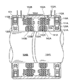
図1は、本発明の実施の形態のタンデム型回転検出装置の断面図である。 FIG. 1 is a cross-sectional view of a tandem rotation detector according to an embodiment of the present invention.
図1に示すように、本発明の実施の形態の回転検出装置は、ハウジング1に回転軸4Aと回転軸4Bとが直列に設けられ、ハウジング1の内側には回転軸4Aの回転角を検出する第1の回転角検出機構2Aと、回転軸4Bの回転角を検出する第2の回転角検出機構2Bとが設けられている。第1の回転角検出機構2Aは、第1のアウタコア部10Aと第1のステータコア部30Aとが平行に設けられ、第1のアウタコア部10Aに対応する内側の位置で第1のインナコア部20Aが回転軸4Aに取り付けられ、第1のステータコア部30Aに対応する内側の位置で第1のロータコア部40Aが回転軸4Aに取り付けられている。
As shown in FIG. 1, in the rotation detection device according to the embodiment of the present invention, a
第1のアウタコア部10Aは、コイル11Aが形成され、コイル11Aの端末は、それぞれ対応する2本のアウタコアピン12A(水平方向に併設)に接続し交流電圧が印加される。第1のインナコア部20Aは、巻線が巻かれコイル21Aが形成されている。
The first
第1のステータコア部30Aは、複数のステータコア歯32Aに巻線が巻かれコイル31Aが形成され、X方向(水平方向)とY方向(垂直方向)ごとに互いに接続されたコイル31Aの4本の端末は、それぞれ対応する4本のステータコアピン32A(水平方向に併設)に接続している。第1のロータコア部40Aは、複数のロータコア歯42Aに巻線が巻かれコイル41Aが形成されている。
In the first
第1の回転角検出機構2Aは、第1のアウタコア部10Aに交流電圧が印加されると、第1のインナコア部20Aを介し発生した磁束による電圧が第1のロータコア部40Aに与えられ第1のロータコア部40Aと第1のステータコア部30Aとは磁気結合し、第1のステータコア部30Aに回転軸4Aの回転角に応じた電圧が誘起され、回転軸4Aの回転角の検出が行われる。また、第2の回転角検出機構2Bは、第1の回転角検出機構2Aと同様に第2のアウタコア部10Bと、第2のインナコア部20Bと、第2のステータコア部30Bと、第2のロータコア部40Bとで構成され、回転軸4Bの回転角の検出が行われる。
In the first rotation
本発明の実施の形態のタンデム型回転検出装置は、第1のアウタコア部10Aのコイル11Aと、第2のアウタコア部10Bのコイル11Bに交流電圧が印加され回転軸4A、4Bの回転角の検出が行われるが、ハウジング1は、例えばSUS303の非磁性材で形成するため、磁束が外部に透過し、漏れ磁束がハウジング1に沿って移動することはなく、漏れ磁束の影響を低減することができる。本発明の実施の形態のタンデム型回転検出装置は、一般の環境下で使用するものであり、外部より強磁性の影響を受けることなく回転角の検出が行われる。なお、回転軸4Aと回転軸4Bとの回転角により、両者間の回転角度差を検出することができる。
In the tandem rotation detection device according to the embodiment of the present invention, an AC voltage is applied to the
図2は、回転軸の回転角に対する検出誤差データの図であり、図2(a)は、従来の実施の形態のタンデム型回転検出装置の検出誤差データであり、図2(b)は、本発明の実施の形態のタンデム型回転検出装置の検出誤差データである。 FIG. 2 is a diagram of detection error data with respect to the rotation angle of the rotation shaft, FIG. 2A is detection error data of the tandem rotation detection device of the conventional embodiment, and FIG. It is detection error data of the tandem type | mold rotation detection apparatus of embodiment of this invention.
本発明の実施の形態のタンデム型回転検出装置は、回転軸4A、4B(図1参照)の回転角を第1、第2のステータコア部30A、30B(図1参照)より電気角で検出し、回転軸4Aと回転軸4Bとの回転角度差(度)は、第1、第2のステータコア部30A、30Bより検出する回転角の差として検出する。従来のタンデム型回転検出装置も、同様にして、回転軸の回転角と、回転角度差(度)を検出する。
In the tandem rotation detection device according to the embodiment of the present invention, the rotation angles of the
図2(a)は、横軸に従来のタンデム型回転検出装置の機械的の回転角度差θ(度)を示し、縦軸に機械的の回転角度差θ(度)に対する検出誤差(分)を示す。図2(a)に示すように、従来のタンデム型回転検出装置の検出誤差データΔθhは、漏れ磁束109A(図3参照)の影響を受け、高い値を示していることが分かる。なお、回転角の検出は、図2に示す第1のステータコア部130Aのステータコア歯132Aと、第1のロータコア部140Aのロータコア歯142Aの設定数に応じた角度ごとに繰り返し行われ、検出誤差データΔθhも周期的に繰り返される山形波形の値を示している。
FIG. 2A shows the mechanical rotation angle difference θ (degrees) of the conventional tandem rotation detector on the horizontal axis, and the detection error (minutes) with respect to the mechanical rotation angle difference θ (degrees) on the vertical axis. Indicates. As shown in FIG. 2A, it can be seen that the detection error data Δθh of the conventional tandem type rotation detection device is affected by the leakage
図2(b)は、横軸に本発明の実施の形態のタンデム型回転検出装置の機械的の回転角度差θ(度)を示し、縦軸に回転角度差θ(度)に対する検出誤差(分)を示す。図2(b)に示すように、本発明の実施の形態のタンデム型回転検出装置の検出誤差データΔθiは、0度から360度の全般に亘り1分以内の極めて低い値を示していることが分かる。本発明の実施の形態のタンデム型回転検出装置は、従来のタンデム型回転検出装置と同様に回転角の検出が繰り返し行われるが、検出誤差データΔθhが全般に亘り極めて低い値を示しているため、全般に亘りフラットの極めて低い値を示している。 In FIG. 2B, the horizontal axis indicates the mechanical rotation angle difference θ (degrees) of the tandem rotation detection device according to the embodiment of the present invention, and the vertical axis indicates a detection error (with respect to the rotation angle difference θ (degrees)). Minutes). As shown in FIG. 2 (b), the detection error data Δθi of the tandem rotation detection device according to the embodiment of the present invention shows an extremely low value within one minute over the entire range from 0 degrees to 360 degrees. I understand. The tandem rotation detection device according to the embodiment of the present invention repeatedly detects the rotation angle in the same manner as the conventional tandem rotation detection device, but the detection error data Δθh shows a very low value in general. In general, the flat value is extremely low.
図2から分かるように、本発明の実施の形態のタンデム型回転検出装置は、前記した漏れ磁束の影響を低減することにより、検出誤差データΔθiが、従来のタンデム型回転検出装置の検出誤差データΔθhに対し約半分の極めて低い値になっており、常に精度の高い検出ができる。 As can be seen from FIG. 2, in the tandem rotation detection device according to the embodiment of the present invention, the detection error data Δθi is reduced to the detection error data of the conventional tandem rotation detection device by reducing the influence of the leakage magnetic flux. The value is about half that of Δθh, and detection with high accuracy is always possible.
以上述べたように、本発明の実施の形態のタンデム型回転検出装置は、一般の磁界環境下において、回転角検出機構間の漏れ磁束の影響を低減し、常に精度の高い検出を行うことができる。 As described above, the tandem rotation detection device according to the embodiment of the present invention can reduce the influence of leakage magnetic flux between the rotation angle detection mechanisms in a general magnetic field environment, and always perform highly accurate detection. it can.
なお、本発明の実施の形態のタンデム型回転検出装置は、第1の回転角検出機構2Aと第2の回転角検出機構2Bとの間に遮蔽板5を設け、回転角検出機構間の漏れ磁束の影響をさらに低減することもできる。
In the tandem rotation detection device according to the embodiment of the present invention, the shielding
さらに、本発明の実施の形態のタンデム型回転検出装置は、回転軸4Aと回転軸4Bとの回転角の検出を行う回転検出装置につき説明したが、これに限定することなく、回転軸4Aと回転軸4Bとを1本の回転軸とし、2個の回転角検出機構により1本の回転軸のトルクの検出を行うこともできる。
Furthermore, although the tandem type rotation detection device according to the embodiment of the present invention has been described with respect to the rotation detection device that detects the rotation angle between the
1、ハウジング
4A、4B 回転軸
2A 第1の回転角検出機構
2B 第2の回転角検出機構
5 遮蔽板
10A、50A 第1のアウタコア部
10B、50B 第2のアウタコア部
17a、17b、57a、57b 巻線、
13a、13b、14a、14b、55a、55b、56a、56b 巻線端末
11A、11B、21A、31A、41A、51A、51B コイル
18、58 交流発振器
20A 第1のインナコア部
20B 第2のインナコア部
30A 第1のステータコア部
30B 第2のステータコア部
40A 第1のロータコア部
40B 第2のロータコア部
DESCRIPTION OF
13a, 13b, 14a, 14b, 55a, 55b, 56a, 56b Winding terminal 11A, 11B, 21A, 31A, 41A, 51A, 51B Coil 18, 58
Claims (4)
Priority Applications (3)
| Application Number | Priority Date | Filing Date | Title |
|---|---|---|---|
| JP2003357360A JP2005121501A (en) | 2003-10-17 | 2003-10-17 | Tandem rotation detector |
| US10/950,832 US20050083042A1 (en) | 2003-10-17 | 2004-09-27 | Tandem rotation detector |
| EP04256172A EP1524510A1 (en) | 2003-10-17 | 2004-10-06 | Tandem rotation detector |
Applications Claiming Priority (1)
| Application Number | Priority Date | Filing Date | Title |
|---|---|---|---|
| JP2003357360A JP2005121501A (en) | 2003-10-17 | 2003-10-17 | Tandem rotation detector |
Publications (2)
| Publication Number | Publication Date |
|---|---|
| JP2005121501A true JP2005121501A (en) | 2005-05-12 |
| JP2005121501A5 JP2005121501A5 (en) | 2005-07-28 |
Family
ID=34373618
Family Applications (1)
| Application Number | Title | Priority Date | Filing Date |
|---|---|---|---|
| JP2003357360A Pending JP2005121501A (en) | 2003-10-17 | 2003-10-17 | Tandem rotation detector |
Country Status (3)
| Country | Link |
|---|---|
| US (1) | US20050083042A1 (en) |
| EP (1) | EP1524510A1 (en) |
| JP (1) | JP2005121501A (en) |
Cited By (4)
| Publication number | Priority date | Publication date | Assignee | Title |
|---|---|---|---|---|
| WO2012108477A1 (en) * | 2011-02-08 | 2012-08-16 | 株式会社ジェイテクト | Torque detecting apparatus |
| JP2012163494A (en) * | 2011-02-08 | 2012-08-30 | Jtekt Corp | Torque detector |
| JP2012163492A (en) * | 2011-02-08 | 2012-08-30 | Jtekt Corp | Torque detector |
| JP2012163493A (en) * | 2011-02-08 | 2012-08-30 | Jtekt Corp | Torque detector |
Families Citing this family (1)
| Publication number | Priority date | Publication date | Assignee | Title |
|---|---|---|---|---|
| CN111630341B (en) * | 2018-01-23 | 2022-04-05 | 株式会社阿米泰克 | Induction type rotation detection device |
Family Cites Families (4)
| Publication number | Priority date | Publication date | Assignee | Title |
|---|---|---|---|---|
| US4724710A (en) * | 1986-12-22 | 1988-02-16 | General Motors Corporation | Electromagnetic torque sensor for a rotary shaft |
| US5012169A (en) * | 1988-07-20 | 1991-04-30 | Yokogawa Electric Corporation | Motor drive system |
| US5062306A (en) * | 1989-04-20 | 1991-11-05 | Kabushiki Kaisha Toyoda Jidoshokki Seisakusho | Apparatus for detecting torque of rotating shaft |
| JP3831841B2 (en) * | 2001-09-26 | 2006-10-11 | ミネベア株式会社 | High precision torque measuring device |
-
2003
- 2003-10-17 JP JP2003357360A patent/JP2005121501A/en active Pending
-
2004
- 2004-09-27 US US10/950,832 patent/US20050083042A1/en not_active Abandoned
- 2004-10-06 EP EP04256172A patent/EP1524510A1/en not_active Withdrawn
Cited By (5)
| Publication number | Priority date | Publication date | Assignee | Title |
|---|---|---|---|---|
| WO2012108477A1 (en) * | 2011-02-08 | 2012-08-16 | 株式会社ジェイテクト | Torque detecting apparatus |
| JP2012163494A (en) * | 2011-02-08 | 2012-08-30 | Jtekt Corp | Torque detector |
| JP2012163492A (en) * | 2011-02-08 | 2012-08-30 | Jtekt Corp | Torque detector |
| JP2012163493A (en) * | 2011-02-08 | 2012-08-30 | Jtekt Corp | Torque detector |
| US9057652B2 (en) | 2011-02-08 | 2015-06-16 | Jtekt Corporation | Torque detecting apparatus |
Also Published As
| Publication number | Publication date |
|---|---|
| US20050083042A1 (en) | 2005-04-21 |
| EP1524510A1 (en) | 2005-04-20 |
Similar Documents
| Publication | Publication Date | Title |
|---|---|---|
| KR100913631B1 (en) | Multirotation type encoder | |
| US7199691B2 (en) | Flat resolver | |
| EP1918681A1 (en) | Angle detector | |
| KR101555804B1 (en) | Rotary electric machine | |
| JP7076780B2 (en) | Core structure and strain detector for detecting changes in permeability | |
| TW201403032A (en) | Magnetic rotation angle detector | |
| JP7076781B2 (en) | Core and strain detectors for detecting changes in permeability | |
| JP2005164531A (en) | Magnetostrictive torque sensor | |
| JP5886269B2 (en) | Rotation detection device and motor | |
| JP5133765B2 (en) | Internal magnet type motor and design method thereof | |
| JP2005121501A (en) | Tandem rotation detector | |
| JP2009247112A (en) | Magnetic flux interference reducing type redundant resolver structure | |
| US9441942B2 (en) | Resolver and multiple-rotation detector | |
| JP2005102374A (en) | Shielding structure for brushless type revolution detector | |
| JP2008029070A (en) | Angle detector | |
| JP3984213B2 (en) | Tandem rotation detector | |
| WO2020195003A1 (en) | Motor | |
| CN109687677B (en) | Rotary transformer stator | |
| JPS6031005A (en) | Detector of position of rotary angle | |
| WO2022260070A1 (en) | Motion detector | |
| US20220286003A1 (en) | Motor | |
| JP2022187942A (en) | motion detector | |
| KR20210100896A (en) | Motor | |
| JP2023051163A (en) | rotation detector | |
| KR20210078102A (en) | Motor |
Legal Events
| Date | Code | Title | Description |
|---|---|---|---|
| A521 | Written amendment |
Free format text: JAPANESE INTERMEDIATE CODE: A523 Effective date: 20050208 |
|
| A621 | Written request for application examination |
Free format text: JAPANESE INTERMEDIATE CODE: A621 Effective date: 20050711 |
|
| A977 | Report on retrieval |
Free format text: JAPANESE INTERMEDIATE CODE: A971007 Effective date: 20070302 |
|
| A131 | Notification of reasons for refusal |
Free format text: JAPANESE INTERMEDIATE CODE: A131 Effective date: 20070320 |
|
| A02 | Decision of refusal |
Free format text: JAPANESE INTERMEDIATE CODE: A02 Effective date: 20071002 |