JP2005118417A - Game machine - Google Patents
Game machine Download PDFInfo
- Publication number
- JP2005118417A JP2005118417A JP2003358985A JP2003358985A JP2005118417A JP 2005118417 A JP2005118417 A JP 2005118417A JP 2003358985 A JP2003358985 A JP 2003358985A JP 2003358985 A JP2003358985 A JP 2003358985A JP 2005118417 A JP2005118417 A JP 2005118417A
- Authority
- JP
- Japan
- Prior art keywords
- setting
- set value
- value
- changed
- switch
- Prior art date
- Legal status (The legal status is an assumption and is not a legal conclusion. Google has not performed a legal analysis and makes no representation as to the accuracy of the status listed.)
- Pending
Links
Images


Abstract
Description
本発明は、遊技操作に応じて入賞特典を付与する遊技機に係り、特にその入賞特典を付与するべき確率を設定する一方、この設定を変更することも可能な遊技機に関する。 The present invention relates to a gaming machine that grants a prize privilege in accordance with a game operation, and more particularly to a gaming machine that sets a probability that the prize bonus should be granted and can change this setting.
この種の遊技機に関する従来の技術として、遊技者に有利な状態を発生させる確率に対応する設定値を段階的に変更可能な遊技機が知られている(例えば、特許文献1参照。)。この公知の遊技機は確率の設定制御を行う設定制御手段を備えており、この設定制御手段に対して指示手段から設定値に関する指示を与えることで、1〜6まで段階的に設定値の変更が可能となっている。また、具体的な設定値は表示手段により表示することができ、このとき表示手段は、設定値が変更可能な状態であるか否かを同時に表示するものとなっている。さらに設定制御手段には、設定値の変更が可能な設定変更モードと、その確認表示のみが可能な設定確認モードとが用意されており、それぞれのモードによって設定値の表示態様を異ならせることができる。 As a conventional technique related to this type of gaming machine, a gaming machine is known in which a setting value corresponding to a probability of generating a state advantageous to a player can be changed in stages (see, for example, Patent Document 1). This known gaming machine has setting control means for performing probability setting control, and the setting value is changed stepwise from 1 to 6 by giving an instruction regarding the setting value from the instruction means to the setting control means. Is possible. Further, the specific set value can be displayed by the display means, and at this time, the display means simultaneously displays whether or not the set value can be changed. Further, the setting control means is provided with a setting change mode in which the setting value can be changed and a setting confirmation mode in which only the confirmation display is possible. The display mode of the setting value can be varied depending on each mode. it can.
上述した公知の遊技機によれば、例えば遊技場の運営者等が遊技機の調整作業を行う際、表示手段の表示態様をみれば、現在のモードで設定変更が可能であるか否かをすぐに判断することができるので、必要な場合は適宜モードを切り替えることで設定値の変更作業をスムーズに行うことができると考えられる。
この種の遊技機における設定値は、それがより高い段階を表すほど抽選に当る確率が高く、それだけ遊技機の出玉率を高くするものであり、通常、遊技機の設定値をどの段階に決めるかは遊技場の運営者がその経営判断に基づいて厳格に管理するべき性質のものである。このため通常の遊技者からみれば、遊技機の設定値がどの程度の段階であるかはきわめて重大な関心事であるとともに、遊技場内ではなるべく高設定の台を探し当てることが遊技を行う上で一つの興趣ともなっている。その反面、不正に出玉を得ることを意図する遊技者からみれば、遊技機の設定値は不正行為をはたらく上で格好の標的になりやすい。なぜなら設定値は、これを不正に変更することで遊技場運営者の意に反して多くの出玉を得ることが可能になるため、不正遊技者が何らかの形で設定値の変更に介入しようとすることは充分に考えられるからである。 For this type of gaming machine, the higher the level it represents, the higher the probability of winning the lottery, and the higher the gaming machine's payout rate. It depends on the management of the amusement hall based on its management judgment. For this reason, from the point of view of a normal player, the level of the setting value of the gaming machine is a very important concern, and in the game room, finding a high setting base as much as possible in the game hall It is also an interest. On the other hand, from the point of view of a player who intends to illegally obtain a game, the setting value of the gaming machine is likely to be a good target for carrying out an illegal act. Because the setting value can be changed illegally, it will be possible to get a lot of games against the will of the game hall operator, so an unauthorized player will try to intervene in changing the setting value in some way It is because it is considered enough.
上述した公知の遊技機の場合、設定変更の際に設定ボタンスイッチが1回操作されるごとに設定値が1段階ずつ順番に繰り上がっていくものとなっている。このため例えば、不正遊技者がある程度続けて遊技を行った上で、出目の状況等からその台の設定値があまり高くない段階にあると想像すると、不正に設定ボタンスイッチの操作に介入することで現状から1つ上の段階に設定値をむりやり変更することができてしまう。さらにこの状態で不正遊技者が引き続き遊技を行い、未だ設定値がそれほど高くない段階にあると想像すると、再度、不正に設定ボタンスイッチの操作に介入することで、また1つ上の段階に設定値を変更することができてしまう。このような不正が数回繰り返されると、本来は遊技場運営者が意図していない高い段階まで遊技機の設定値が引き上げられ、不正に多くの出玉を奪われてしまう。 In the case of the above-described known gaming machine, the setting value is incremented by one step each time the setting button switch is operated once when the setting is changed. For this reason, for example, if an illegal player continues playing to some extent and imagines that the set value of the stand is not so high due to the appearance status, etc., illegally intervene in the operation of the setting button switch This makes it possible to change the setting value one step above the current situation. Furthermore, if it is assumed that the unauthorized player continues to play in this state and the setting value is not so high yet, it is set again by illegally intervening in the operation of the setting button switch. The value can be changed. If such fraud is repeated several times, the set value of the gaming machine is raised to a high level that is not originally intended by the game hall operator, and many balls are illegally stolen.
もちろん、こうした不正な設定変更は決して容易なものではなく、公知の遊技機においても設定制御手段を設定値変更モードに移行させるためには、遊技場運営者が管理する専用の設定キーを用いてスイッチを操作する必要がある。しかしながら、設定キースイッチの操作信号は単なる接点信号(ON信号)でしかないため、(特許文献1の図9等を参照)、不正遊技者が例えば遊技機の筐体に金属片等を挿入し、設定キースイッチの接点(またはこれにつながる配線)をむりやり短絡させるだけでも設定値変更モードに移行する。さらに、この状態で設定ボタンスイッチの接点を何度が短絡させれば、その接点信号(パルス信号)が入力されるごとに1つずつ上の段階に設定値を変更することが可能となってしまう。 Of course, such illegal setting changes are not easy, and even in known game machines, in order to shift the setting control means to the setting value change mode, a dedicated setting key managed by the game hall operator is used. It is necessary to operate the switch. However, since the operation signal of the setting key switch is merely a contact signal (ON signal) (see FIG. 9 of Patent Document 1), an unauthorized player inserts a metal piece or the like into the casing of the gaming machine, for example. The setting key change mode can be entered simply by forcibly short-circuiting the contact of the setting key switch (or the wiring connected thereto). Furthermore, if the contact of the setting button switch is short-circuited many times in this state, it is possible to change the set value one step each time the contact signal (pulse signal) is input. End up.
そこで本発明は、遊技機における不正な設定変更の防止に有効な対策を施すことを課題としたものである。 Therefore, an object of the present invention is to take effective measures for preventing unauthorized setting changes in gaming machines.
(解決手段1)
本発明の遊技機は、遊技者による遊技操作に応じて抽選を行い、この抽選に当たったときに所定の入賞特典を遊技者に付与するものである。遊技操作とは、例えば回胴式遊技機では図柄表示器による図柄の変動を開始させるために行われる各種の操作であったり、弾球式遊技機では遊技領域内で遊技球を入賞させるために行われる各種の操作であったりする。こうした遊技操作に応じて遊技機では抽選が行われるが、この抽選に当たる確率は設定回路によって段階的に設定可能である。また設定の段階を表す設定値は、所定のスイッチを操作することで変更可能となっており、特に本発明ではスイッチ操作に対して設定値が単純な態様で変更されないものとなっている。
(Solution 1)
The gaming machine of the present invention performs a lottery in accordance with a game operation by a player, and gives a predetermined prize to the player when the lottery is won. The game operation is, for example, various operations performed to start the fluctuation of the symbol by the symbol display in the case of the spinning-type game machine, or in order to win the game ball in the game area in the case of the ball ball game machine It may be various operations to be performed. A lottery is performed in the gaming machine in accordance with such a game operation, and the probability of winning the lottery can be set in stages by a setting circuit. The setting value representing the setting stage can be changed by operating a predetermined switch. In particular, in the present invention, the setting value is not changed in a simple manner with respect to the switch operation.
(解決手段2)
すなわち本発明の遊技機は、遊技者による遊技操作に応じて抽選を行い、この抽選に当たったときに所定の入賞特典を遊技者に付与するものであって、その構成には、抽選に当たる確率を段階的に設定し、この設定の段階を表す設定値に対応して確率の高低度合いを異ならせる設定回路と、設定回路に接続されて設定値を変更するべく操作されるスイッチを有し、このスイッチに対する操作がなされたとき、設定値を段階的にみて不規則に変更させる設定変更手段とを備えたものとなっている。
(Solution 2)
That is, the gaming machine of the present invention performs a lottery in accordance with the player's gaming operation, and gives a predetermined prize bonus to the player when the lottery is won, and the configuration has a probability of winning the lottery. And a setting circuit that varies the degree of probability corresponding to the setting value representing the setting stage, and a switch that is connected to the setting circuit and is operated to change the setting value. When this switch is operated, it is provided with setting changing means for changing the setting value irregularly in a stepwise manner.
本発明の遊技機においても、抽選に当たる確率は設定回路において段階的に設定されており、この設定の段階を表す設定値に対応して確率の高低度合いが異なる。例えば、設定値が1からNまでの自然数で表されるとすると、確率の高低度合いは全部でN段階となり、設定値が段階的にみて高ければ、それだけ抽選に当る確率も高く設定されているといえる。 Also in the gaming machine of the present invention, the probability of winning the lottery is set stepwise in the setting circuit, and the level of probability varies depending on the set value representing the setting stage. For example, if the set value is represented by a natural number from 1 to N, the degree of probability is N stages in total, and the higher the set value is, the higher the probability of winning the lottery. It can be said.
上記の設定値を変更する操作を行うために設定変更手段はスイッチを有しているが、このスイッチに対する操作がなされても、その都度1段階ずつ設定値が変更されていくのではなく、段階的にみて不規則に設定値が変更される。したがって例えば、変更の前と後では設定値が2段階以上かけ離れていたり、1度目のスイッチ操作で一旦は上の段階に変更されたものが2度目のスイッチ操作では逆に下の段階に変更されたり、あるいは、スイッチ操作が数回繰り返されても設定値の段階が変化しなかったりすることになる。 The setting changing means has a switch for performing the operation for changing the set value. However, even if the switch is operated, the set value is not changed step by step. The setting value is changed irregularly. Therefore, for example, before and after the change, the set value is more than two steps away, or once it was changed to the upper step by the first switch operation, it is changed to the lower step by the second switch operation. Or, even if the switch operation is repeated several times, the set value level does not change.
この結果、不正遊技者が単純な接点ショート等の手口を用いて設定値の変更を試みたとしても、それによって必ず意図したとおりに設定値を1段階ずつ繰り上げることができなくなるので、不正行為を有効に防止することができる。 As a result, even if an unauthorized player tries to change the set value using a simple technique such as a contact short-circuit, the set value cannot be incremented step by step as intended. It can be effectively prevented.
(解決手段3)
上記の解決手段2において、設定変更手段による不規則な設定値の変更手法は、例えば以下に挙げる態様により実現可能である。
第1の方法論として、設定変更手段は設定値を段階的に順次繰り上げる態様で変更するものであり、この変更に際して設定値が次の段階へ繰り上がるまでに要するスイッチの操作回数を不定に異ならせることができる。
(Solution 3)
In the
As a first methodology, the setting change means changes the setting value in a manner that gradually advances the setting value step by step. In this change, the number of switch operations required until the setting value is advanced to the next step is made indefinitely different. be able to.
この場合、設定変更の際に設定値は段階的に順次繰り上がっていくものとなっているが、1段階上に設定値を変更するのに何回スイッチ操作を要するかが一定でない。例えば、設定変更の際に1回のスイッチ操作で設定値が繰り上がる場合もあれば、2回、3回とスイッチ操作を行っても設定値が繰り上がらない場合もあり得る。 In this case, when the setting is changed, the setting value is gradually increased step by step. However, it is not constant how many times the switch operation is required to change the setting value by one step. For example, when the setting is changed, the set value may be increased by a single switch operation, or the set value may not be increased even if the switch operation is performed twice or three times.
したがって、不正遊技者が単純な接点ショート等の手口を用いて設定値の変更を試みたとしても、少なくとも1度の不正操作で必ず設定値が繰り上がるとは限らず、不正遊技者の意図する段階まで計画的に設定値を引き上げることはきわめて困難となる。さらに、数回のスイッチ操作によって設定値が繰り上がったとしても、また次に設定値が繰り上がるのに要する操作回数が前と異なることもあり得るので、不正な設定変更はますます至難となる。 Therefore, even if an unauthorized player attempts to change the set value using a simple contact short-circuit technique, the set value is not always increased by at least one unauthorized operation. It is extremely difficult to raise the set value systematically to the stage. Furthermore, even if the set value is increased by several switch operations, the number of operations required to increase the next set value may be different from the previous one, making unauthorized setting changes increasingly difficult. .
(解決手段4)
あるいは上記の解決手段2において、設定変更手段は設定値を段階的に順次繰り上げる態様で変更するものであり、この変更に際して設定値が次の段階へ繰り上がるまでに要するスイッチの操作時間を不定に異ならせるものであってもよい。
(Solution 4)
Alternatively, in the solving means 2, the setting changing means changes the setting value in a stepwise manner in a stepwise manner, and the switch operation time required for the setting value to be advanced to the next step upon this change is indefinite. It may be different.
これは例えば、スイッチの操作時間、つまり、スイッチに対する操作入力が継続されている時間の長さをスイッチの操作回数に置き換えたものと考えることができる。この場合、不正遊技者が接点ショート等の手口を用いて単発的に接点信号を発生させたとしても、このような短時間内の接点ショートだけでは設定値の変更が行われないので、上記解決手段3と同様に不正な設定変更を行うことは困難を極める。
For example, it can be considered that the operation time of the switch, that is, the length of time during which the operation input to the switch is continued is replaced with the number of times of operation of the switch. In this case, even if a fraudulent player generates a contact signal once using a technique such as a contact short circuit, the set value is not changed only by the contact short circuit within such a short time. As in the case of
(解決手段5)
上記の解決手段4において、設定変更手段はスイッチが所定の規定時間にわたって操作されたときのみ設定値を次の段階へ繰り上げて変更する一方、スイッチの操作時間が規定時間に満たなかったとき、設定値を現状以下の段階に変更するものであってもよい。
(Solution 5)
In the
この場合、設定値を次の段階へ繰り上げるためには必ず規定時間にわたってスイッチを操作し続けなければならず、そうでない場合は設定値が現状のまま維持されるか、あるいは現状より低い段階に変更されることとなる。したがって、不正遊技者が単純な接点ショート等の手口を試みた場合、単発的に接点信号を発生させただけでは設定値が繰り上がらないばかりか、現状より低い段階に移行してしまう場合もあるので、不正目的を達成することは全く容易でなくなる。特に、設定値が現状よりも低い段階へ移行してしまった場合は不正遊技者が自ら不利な遊技条件をもたらす結果となり、不正行為をはたらいたことが災いして自業自得となる。 In this case, in order to advance the set value to the next stage, the switch must be continuously operated for a specified time. Otherwise, the set value is maintained as it is or changed to a lower stage than the current level. Will be. Therefore, when a fraudulent player attempts a simple contact short-circuit technique, not only does the set value not be increased by generating a contact signal once, but it may also shift to a lower stage than the current level. Therefore, it is not easy to achieve the fraudulent purpose. In particular, if the set value shifts to a lower level than the current state, the illegal player will bring an unfavorable game condition on his own, and the misconduct will be lost and self-employed.
(解決手段6)
あるいは、上記の解決手段2において設定変更手段は、予め設定値の変更順序を段階的にみて不規則に定めた変更パターンを有しており、スイッチに対する操作がなされたとき、変更パターンにより定められた変更順序にしたがって設定値を変更するものであってもよい。
(Solution 6)
Alternatively, in the
この場合、変更パターンには予め設定値の変更順序が定められており、スイッチ操作がなされるごとに一定の変更順序にしたがって設定値が変更されることとなるが、その順序が変則的なパターンであれば、「段階的にみて不規則」に設定値が変更されるということができる。したがってこの場合も同様に、単純な接点ショート等による手口を用いて不正な設定変更をはたらくことはきわめて困難となる。 In this case, the change pattern has a predetermined change order in the set value, and the set value is changed according to a fixed change order every time the switch is operated. Then, it can be said that the setting value is changed to “irregular in terms of steps”. Accordingly, in this case as well, it is extremely difficult to make an illegal setting change using a simple contact short circuit or the like.
(解決手段7)
次に第2の方法論として、上記の解決手段2において設定変更手段は、設定値の段階別にそれぞれ対応する複数のスイッチを有しており、これら複数のスイッチのうち、操作がなされたスイッチに対応する段階へ設定値を直接変更させることができる。
(Solution 7)
Next, as a second methodology, in the
上述した第1の方法論では、1回のスイッチ操作と設定値の繰り上げ変更とが必ずしも対応していない場合を各種取り上げているが、第2の方法論ではスイッチ操作に応じて設定値が各段階へ直接変更されることで不規則性を実現している。例えば、遊技場運営者が現状に対して変更を意図する設定値が決まっている場合、その段階に対応した特定のスイッチを操作することで所望の設定値にダイレクトに変更することができる。この場合も同様に、設定変更の際に操作されるスイッチに基づいて設定値はとびとびに変更されるため、第1の方法論と同様に設定値は「段階的にみて不規則」に変更される。 In the first methodology described above, various cases are described in which a single switch operation does not necessarily correspond to a setting value advance change. In the second methodology, the set value is changed to each stage according to the switch operation. Irregularity is realized by changing directly. For example, when a setting value that the game hall operator intends to change is determined for the current situation, it can be changed directly to a desired setting value by operating a specific switch corresponding to that stage. In this case as well, since the setting value is changed in succession on the basis of the switch operated when changing the setting, the setting value is changed to “irregular in terms of steps” as in the first methodology. .
なお、設定値の各段階とスイッチ操作とを対応させるためには、スイッチ操作によって単なる接点信号を発生させるのではなく、操作されたスイッチに応じて設定値の段階を表す信号を発生させる必要が生じる。したがって、単純な接点ショートだけで設定値を変更することは技術的に不可能となるので、不正な設定変更を確実に抑止することができる。 In order to make each step of the set value correspond to the switch operation, it is necessary not to generate a simple contact signal by the switch operation but to generate a signal representing the set value step according to the operated switch. Arise. Therefore, since it is technically impossible to change the set value only by a simple contact short-circuit, an illegal setting change can be reliably suppressed.
(解決手段8)
より具体的には、上記の解決手段7において設定変更手段は、スイッチに対する操作がなされたとき、それぞれの対応する設定値の段階を表す識別信号を生成し、この識別信号により表される段階に設定値を変更させる態様が好ましい。識別信号には、例えば設定値の段階をコード化したものを用いることができ、正規のスイッチ操作によって識別信号が生成されない限り設定値の変更は不能となる。
(Solution 8)
More specifically, in the above solution means 7, the setting changing means generates an identification signal indicating the stage of each corresponding set value when an operation is performed on the switch, and at the stage represented by this identification signal. A mode in which the set value is changed is preferable. As the identification signal, for example, a coded set value stage can be used, and the setting value cannot be changed unless the identification signal is generated by a proper switch operation.
(解決手段9)
本発明の遊技機には、さらに以下の構成を付加することができる。
すなわち上記の解決手段2から8において、本発明の遊技機はその本体の前面を覆い、その内側にてスイッチを遮蔽する開閉可能な扉部材と、扉部材に設けられて設定値を表示可能な表示手段と、扉部材の開閉状態を検出する開閉状態検出手段と、開閉状態検出手段により扉部材が開かれていることが検出されているときのみ、表示手段による設定値の表示を許容する表示許可手段とをさらに備えていてもよい。
(Solution 9)
The gaming machine of the present invention can be further added with the following configuration.
That is, in the
例えば、遊技場運営者の管理下において正規に設定値の変更を行う場合は、遊技機の本体前面を覆う扉部材の施錠を解除し、これを開放してスイッチを操作する態様が通常である。この場合、現状の設定値がどの段階にあるのかを表示手段にて確認することができ、作業者が目的とする設定値を確認したうえで設定値の変更を確定し、その作業を終了することができる。この後、扉部材を閉じてこれを施錠すると、スイッチがその内側にて遮蔽されるため、通常の遊技者からスイッチは視認されず、かつ、その操作がなされることはない。 For example, when a set value is regularly changed under the management of a game hall operator, a mode in which the door member covering the front of the main body of the gaming machine is unlocked, and this is opened to operate the switch is normal. . In this case, it is possible to confirm at which stage the current set value is in the display means, the operator confirms the target set value, confirms the change of the set value, and ends the work be able to. Thereafter, when the door member is closed and locked, the switch is shielded on the inside thereof, so that the normal player does not see the switch and the operation is not performed.
これに対し、不正を意図する遊技者は、例えば扉部材による遮蔽部分をかいくぐって遊技機本体の内部に金属片等を挿入し、接点ショート等による不正行為をはたらこうとする。このような場合に、たとえ設定回路において設定値の変更が可能な状態に移行されたとしても、扉部材が閉じられている場合は表示手段による設定値の表示が許容されていないため、不正遊技者に現状の設定値や変更後の設定値を具体的に知られることはない。 On the other hand, a player who intends to cheat attempts to act illegally by, for example, inserting a metal piece or the like inside the main body of the gaming machine through a shielded portion by a door member. In such a case, even if the setting circuit shifts to a state in which the setting value can be changed, if the door member is closed, the display of the setting value by the display means is not permitted. The user does not specifically know the current setting value or the changed setting value.
このように、扉部材が閉じられているときに設定値を非表示とする機能が遊技機に付加されていれば、不正遊技者に設定値の情報を盗まれることはない。また上記のように、設定値が段階的にみて不規則に変更されることと相まって、不正行為の抑止効果を有効に発揮することができる。 As described above, if the gaming machine is added with a function of not displaying the setting value when the door member is closed, the information on the setting value is not stolen by an unauthorized player. In addition, as described above, coupled with the fact that the setting value is changed irregularly in a stepwise manner, it is possible to effectively exert the deterrent effect.
(解決手段10)
さらに上記の解決手段2から9において、設定変更手段は、遊技機本体の前面を覆う扉部材が閉じた状態でその内側に前記スイッチが遮蔽されているとき設定値を不規則に変更させ、一方、扉部材が開かれた状態でスイッチが遊技機本体の前面側に開放されているとき設定値を段階的に変更させる態様であってもよい。この場合、遊技機は扉部材の開閉状態を検出するため上記の開閉状態検出手段をさらに備えることが好ましい。
(Solution 10)
Further, in the above solution means 2 to 9, the setting change means changes the set value irregularly when the switch is shielded on the inside with the door member covering the front surface of the gaming machine main body closed. The setting value may be changed step by step when the switch is opened to the front side of the gaming machine main body with the door member opened. In this case, it is preferable that the gaming machine further includes the above-described open / close state detection means for detecting the open / close state of the door member.
あるいは解決手段2から8において、遊技機はその本体の前面を覆い、その内側にてスイッチを遮蔽する開閉可能な扉部材と、扉部材の開閉状態を検出する開閉状態検出手段とをさらに構成として備えるものとしてもよい。この場合、設定変更手段は、開閉状態検出手段により扉部材が閉じられていることが検出されているときに設定値を不規則に変更させ、一方、開閉状態検出手段により扉部材が開かれていることが検出されているときに設定値を段階的に変更させる態様とすることもできる。 Alternatively, in the solving means 2 to 8, the gaming machine further comprises an openable / closable door member that covers the front surface of the main body and shields the switch inside thereof, and an open / closed state detecting means that detects the open / closed state of the door member. It may be provided. In this case, the setting change means irregularly changes the set value when the door member is detected to be closed by the open / close state detection means, while the door member is opened by the open / close state detection means. It is also possible to adopt a mode in which the set value is changed step by step when it is detected.
いずれにしても、扉部材が閉じられた状態で不正な設定変更への介入がなされたときは、上記の解決手段2から8によって不正行為が有効に防止される。その一方で、遊技場運営者の管理下において正規に設定値の変更作業が行われるときは、扉部材が正規に開放された状態であるため設定値が段階的に変更される結果、例えば1回のスイッチ操作に応じて1段階ずつ設定値が繰り上がる態様となる。このため遊技場運営者にとっては、目的とする設定値への変更作業を容易に行うことができるという利便性がある。特に、扉部材が開かれているときに表示手段による設定値の表示があわせて許容される態様であれば、設定値を確認しながら変更作業ができるため、より一層の利便性がある。 In any case, when an illegal setting change is made with the door member closed, fraudulent acts are effectively prevented by the solving means 2 to 8 described above. On the other hand, when the setting value is regularly changed under the management of the game hall operator, the setting value is changed stepwise because the door member is normally opened. The set value is incremented by one step according to the number of switch operations. For this reason, it is convenient for the game hall operator to easily change the target setting value. In particular, if the setting value display by the display means is allowed when the door member is opened, the change operation can be performed while checking the setting value, which is further convenient.
本発明の遊技機は、従来単純な仕組みであった設定値の変更ロジックを高度化し、不正行為による設定値の変更をきわめて困難なものにすることができる。 In the gaming machine of the present invention, the setting value changing logic, which has been a simple mechanism in the past, can be advanced, and changing the setting value due to fraud can be made extremely difficult.
本発明の実施形態について、以下に掲げる項目に沿って各対応図面を参照しながら説明する。
1.実施形態の概要
1−1.遊技機の基本構成(図1)
1−2.遊技機の内部構成(図2)
2.構成要素の説明
2−1.設定回路
2−2.設定変更手段
2−3.設定変更の従来例
3.具体的方法論の説明
3−1.第1の方法論(図3〜図7)
3−1−1.設定変更処理(1)
3−1−2.設定変更処理(2)
3−1−3.設定変更処理(3)
3−2.第2の方法論(図8,図9)
3−2−1.設定変更処理(4)
4.付加的要素の説明(図10)
4−1.インターロック処理
5.その他の実施形態についての言及。
Embodiments of the present invention will be described along the following items with reference to the corresponding drawings.
1. 1. Outline of Embodiment 1-1. Basic configuration of the gaming machine (Figure 1)
1-2. Internal configuration of gaming machine (Figure 2)
2. 2. Description of components 2-1. Setting circuit 2-2. Setting change means 2-3. 2. Conventional example of setting
3-1-1. Setting change processing (1)
3-1-2. Setting change process (2)
3-1-3. Setting change process (3)
3-2. Second methodology (Figs. 8 and 9)
3-2-1. Setting change process (4)
4). Description of additional elements (Figure 10)
4-1. 4. Interlock processing Reference to other embodiments.
(1.実施形態の概要)
ここでは遊技機の一例として回胴式遊技機(スロットマシン)を挙げているが、本発明の遊技機はパチンコ機に代表される弾球式遊技機の他、遊技球を用いてスロットマシン遊技を実施するタイプの遊技機としても実施可能である。
(1. Overview of Embodiment)
Here, as an example of a gaming machine, a swivel type gaming machine (slot machine) is cited, but the gaming machine of the present invention is a slot machine game using a gaming ball in addition to a ball-type gaming machine represented by a pachinko machine. It can also be implemented as a type of gaming machine that implements.
(1−1.遊技機の基本構成)
図1は、一実施形態として挙げられる回胴式遊技機(以下、単に「スロットマシン」と呼称する。)1を示している。このスロットマシン1は箱形の筐体2を有しており、この筐体2をベースとして遊技場の島設備等に設置される。島設備には複数台のスロットマシン1が幅方向に列をなして配置され、通常、その台間にメダルサンド(図示していない)が付属して配置されている。このメダルサンドに現金を投入すると、その投入金額に見合った枚数分のメダルが貸し出され、遊技者はこれらを用いて遊技を実行することができる。なお遊技媒体は特にメダルやコインだけに限らず、遊技球やトークン等を用いる態様であってもよい。あるいは、台間サンドにプリペイドカードを挿入し、その残り度数とメダル等を交換して遊技を実行できる態様であってもよい。
(1-1. Basic configuration of gaming machine)
FIG. 1 shows a swivel type gaming machine (hereinafter simply referred to as a “slot machine”) 1 that can be cited as an embodiment. The
筐体2は遊技者に相対する前面に前面扉4を有しており、この前面扉4は一側端(この例では左側端)を中心として手前に開くことができる。前面扉4はその中程の位置に透明板6を有しており、その中央には、ほぼ矩形をなす表示窓8が形成されている。
The
一実施形態のスロットマシン1は、機械的な図柄表示器の一例として3つのリール(左リール、中リール、右リール)10a,10b,10cを装備しており、これらリール10a,10b,10cは前面扉4の奥、つまり、筐体2の内部に配置されている。
The
各リール10a,10b,10cの外周にはそれぞれリール帯が張り巡らされており、その表面に各種の図柄が付されている。図1に全ては示されていないが、図柄には例えば、数字の「7」を図案化したものや特定のアルファベット(またはその文字列)を図案化したもの、ベル等の縁起物を図案化したもの、スイカ、リンゴ、チェリー、オレンジ等の青果類を図案化したもの、あるいは、スロットマシン1の機種を特徴付けるキャラクターや図形、記号等を図案化したものが含まれている。
Each
スロットマシン1はこれらリール10a,10b,10cを回転または停止させることで、図柄の表示態様を変動させたり停止させたりすることができる。なお、スロットマシン1の前面からは、表示窓8を透かしてリール10a,10b,10cの一部のみが視認可能であり、その停止時には各リール10a,10b,10cにつき縦方向に3つの図柄が有効に表示されるものとなっている。
The
透明板6のうち、表示窓8の両脇にはそれぞれ表示領域12,14が形成されており、これら表示領域12,14には各種の文字情報や図柄情報が所定の配列で付されている。透明板6の背後には図示しないランプユニットが配置されており、表示領域12,14内の情報はランプの透過光によって点灯表示される。例えば、最初に遊技者がメダル投入口15を通じてメダルを投入すると、その投入枚数に応じてベット数が加算され、このとき左側の表示領域12ではベット数に対応したベットランプ(メダルラインランプ)が点灯表示される。ベット数が最大(例えば3ベット)に達すると、さらに投入されたメダルはクレジットとして貯留され、そのクレジット数は表示部16に数値表示される。
例えば、クレジットは最大で50まで貯留することができ、1回の遊技を終えた後に充分なクレジットの残りがあれば、その分を次回のベットに回すことができる。ベット数の選択はベットボタン18,20,22を操作することで行い、これらベットボタン18,20,22はそれぞれシングルベット(1枚がけ)、2ベット(2枚がけ)、MAXベット(3枚がけ)に対応する。
For example, up to 50 credits can be stored, and if there is sufficient credit remaining after one game, that amount can be passed to the next bet. The bet number is selected by operating the
いずれにしても、ベットランプが点灯表示された状態で遊技者が始動レバー24を操作すると、リール10a,10b,10cが一斉に回転し始めて図柄が変動する。さらに遊技者が停止ボタン26,28,30を操作すると、左・中・右のそれぞれに対応するリール10a,10b,10cが回転を停止して図柄の変動が停止する。このとき、表示窓8内で有効化されている入賞ライン上に一定の図柄の組み合わせ(例えば特定の図柄が一列に揃った状態)が表示されると、遊技者に入賞特典が付与される。ここでの入賞特典としては、例えば所定枚数分のメダルの払い出しや特別遊技状態(いわゆるビッグボーナスゲームやレギュラーボーナスゲーム、あるいは、アシストタイム、チャレンジタイム等)への移行等を挙げることができ、遊技者は特別遊技を実行することでより多くのメダルの払い出しを受けることが可能となる。
In any case, when the player operates the
なお、公知のようにリール10a,10b,10cの停止位置にはリール制御による機械操作が介入する。このため、毎回行われる抽選の結果、フラグがONになっていない役(図柄の組み合わせ)を狙ったとしても、遊技者が意図した通りの位置で狙った図柄が停止しない場合がある。逆に、特定の役についてフラグがONになっていれば、リール制御によって入賞ライン上の位置に特定の図柄が勝手に引き込まれる場合があるので、このときは遊技者の特別な技術介入がなくても図柄を揃えられる。いずれにしても、以下の説明ではそれぞれ有効な入賞ライン上に所定の図柄配列が実現されることを「入賞」と呼称する。
As is well known, machine operation by reel control intervenes at the stop positions of the
以上の遊技操作によって入賞すると、そのときの図柄の種類に応じたメダルの払出枚数が表示部32に表示される。また、ビッグボーナスゲームやレギュラーボーナスゲームに入賞すると、その進行中に残りゲーム数が表示部34に表示されるものとなっている。払い出されたメダルは表示部16のクレジット数が最大になるまでクレジットとして貯留され、最大クレジット数を超えた分のメダルは払出口36を通じて受け皿38に払い出される。また遊技者は、クレジット精算ボタン40を操作することでメダルの貯留(クレジット)を解除し、それまで貯留していたメダルの返却を要求することも可能である。
When a prize is won by the above game operation, the number of medals paid out according to the type of symbol at that time is displayed on the
本実施形態のスロットマシン1は、表示窓8の上方に液晶表示器42を有しており、この液晶表示器42には、遊技の進行に伴う演出のための映像や各種ボーナスゲームでの獲得メダル枚数等が表示されるものとなっている。また、払出口36の左右にそれぞれ一対のスピーカ44が設けられており、これらスピーカ44は遊技の進行に伴う効果音やBGM、音声等を出力することができる。その他、前面扉4には各所にランプ45,46,48が配置されており、これらランプ45,46,48は遊技の進行に合わせて発光装飾による演出を実施することができる。
The
(1−2.遊技機の内部構成)
図2は、スロットマシン1に装備されている各種の機構要素や電子機器類、操作部材等の構成を概略的に示している。スロットマシン1はその遊技の進行を統括的に制御するための主制御基板50を有しており、この主制御基板50にはCPU52をはじめROM54、RAM56等の電子回路が実装されている。また主制御基板50は外部機器と情報をやりとりするためのインタフェース58や、抽選用に乱数を発生させるためのカウンタ62等を備えている。
(1-2. Internal structure of gaming machine)
FIG. 2 schematically shows configurations of various mechanism elements, electronic devices, operation members, and the like that are installed in the
上記のベットボタン18,20,22や始動レバー24、停止ボタン26,28,30、精算ボタン40等はいずれも主制御基板50に接続されており、これら操作ボタン類は図示しないセンサを用いて遊技者による操作を検出し、その操作信号を主制御基板50に出力することができる。
The
またスロットマシン1の筐体2には、主制御基板50とともにその他の機器類が収容されており、これら機器類から主制御基板50に各種の信号が入力されている。機器類にはメダルセレクタ64やリール装置66、ホッパ装置68等があり、このうちメダルセレクタ64はメダル投入口15から投入されたメダルを1枚ずつ検出し、その検出信号を主制御基板50に出力する。
The
リール装置66はリール10a〜10cを含むユニットとして構成されている。リール装置66は各リール10a,10b,10cの回転に関する基準位置を検出するためのインデックスセンサ(図示していない)を有しており、これらインデックスセンサからの検出信号(インデックス信号)が主制御基板50に入力されている。またホッパ装置68は、払い出されたメダルを1枚ずつ検出する払出センサ(図示していない)を有しており、この払出センサからメダル1枚ごとの検出信号が主制御基板50に入力されている。
The
一方、主制御基板50からは、リール装置66やホッパ装置68に対して制御信号が出力される。すなわち、リール装置66は各リール10a,10b,10cを回転させるためのステッピングモータ(図示していない)を内蔵しており、これらステッピングモータの起動および停止を制御するための駆動パルス信号が主制御基板50から出力される。またホッパ装置68には、入賞した図柄の種類に応じて主制御基板50から払出信号が入力され、この払出信号に基づいてホッパ装置68はメダルの払い出し動作を行う。
On the other hand, a control signal is output from the
スロットマシン1は、主制御基板50の他に演出制御基板70を備えており、この演出制御基板70にはCPU72の他に図示しないROMやRAM、インタフェース、VDP(ビデオディスプレイプロセッサ)、音源IC、オーディオアンプ等が装備されている。演出制御基板70は主制御基板50から各種の指令信号を受け、上記の液晶表示器42や表示部16,32,34、スピーカ44の作動を制御するほか、ランプ45,46,48の点灯または点滅を制御している。
The
さらに、主制御基板50には外部端子基板74が接続されており、スロットマシン1はこの外部端子基板74を介して遊技場のホールコンピュータ76に接続されている。外部端子基板74は主制御基板50から送信される投入メダル信号や払出メダル信号、あるいはビッグボーナスゲーム中やレギュラーボーナスゲーム(JACゲーム)中の信号をホールコンピュータ76に中継している。
Further, an external
その他、筐体2の内部には電源ユニット80が収容されている。この電源ユニット80は外部電源から電力を取り込んでスロットマシン1の作動に必要な電力を生成する。ここで生成された電力は、電源ユニット80から各ユニットに供給されている。
In addition, a
(2.構成要素の説明)
次に、一実施形態のスロットマシン1に適用されている本発明の構成要素について説明する。
(2. Explanation of components)
Next, the components of the present invention applied to the
(2−1.設定回路)
設定回路は主制御基板50から構成され、具体的にはそのCPU52やROM54、RAM56等が該当する。主制御基板50は、例えば始動レバー24が操作されたときに抽選を行い、この抽選の結果から遊技者に入賞特典を付与するべきか否かを決定する。設定回路はこのときの抽選に当る確率を段階的に設定し、その段階を表す設定値に応じて抽選確率の高低度合いを異ならせる。なお、スロットマシン1の設定や設定値そのものは公知のものと同様の性質であり、ここではその概略を説明する。
(2-1. Setting circuit)
The setting circuit is composed of a
本実施形態のスロットマシン1では、設定回路において例えば6段階の設定が可能であり、それぞれの段階を表す設定値(1〜6)に応じて上述の入賞特典を付与するべき確率が異なる。具体的には、主制御基板50のROM54には都合6つのテーブルデータ(1〜6)が格納されており、これらテーブルデータ(1〜6)にはそれぞれ、全乱数値(例えば16384通り)に対するビッグボーナスやレギュラーボーナスの当り値が予め与えられている。このうちテーブルデータ(1)は、ビッグボーナスとレギュラーボーナスの当り値が最も少なく、これに対してテーブルデータ(2),(3),(4)の順にテーブルデータ(5)までは当り値の数が増加されている。そして全テーブルデータ中、テーブルデータ(6)はビッグボーナスの当り値を最も多く有している。
In the
主制御基板50のCPU52は、通常遊技中にカウンタ62から取得した乱数値とテーブルデータの当り値とを照合して当りを判定し、いずれかのボーナスゲームに当った場合は対応する図柄のフラグをONにする。この場合、遊技者が狙った図柄の近くで停止ボタン26,28,30を操作すると、上記のリール制御によって可能な範囲(例えば4図柄以内)の停止位置に当り図柄が停止するので、各ボーナスゲームに対応する図柄で入賞しやすくなる。
The
ここで、通常遊技中にいずれのテーブルデータ(1〜6)を使用して当り判定を行うかは設定値によって異なり、当り値の数がより多いテーブルデータを使用して当り判定を行うように設定されているほど、抽選に当る確率が高く、その分、遊技機の出玉率が高く設定されているといえる。このようなテーブルデータ(1〜6)の番号を出玉率の高低段階になぞらえて設定1〜6と称しており、それぞれ1〜6の数値が設定値となる。
Here, which table data (1 to 6) is used for the hit determination during the normal game depends on the set value, and the hit determination is performed using the table data having a larger number of hit values. The higher the setting, the higher the probability of winning a lottery, and it can be said that the gaming machine payout rate is set higher accordingly. Such numbers of the table data (1 to 6) are referred to as
具体的には、ある遊技機において通常遊技中にテーブルデータ(1)を使用して当り判定を行うように設定されていれば、それを設定1であるとか、その遊技機の設定は1であるとか、あるいは設定1の遊技機である等と称し、また、このときの設定値は1であるということができる。同様に、テーブルデータ(2)〜(6)を使用して当り判定を行うように設定されていれば、それぞれ設定2〜6等と称しており、これら2〜6がそのときの設定値となる。
Specifically, if a game machine is set to make a hit determination using table data (1) during a normal game, it is set to 1 or the setting of the game machine is 1. It is referred to as being a game machine with setting 1 or the like, and it can be said that the setting value at this time is 1. Similarly, if the table data (2) to (6) are set to make a hit determination, they are referred to as
(2−2.設定変更手段)
次に遊技機の設定変更について説明する。上記のように遊技機の設定は、それが遊技者に付与される入賞特典の確率の高低を決定するものであって、遊技機の出玉率に直結する性質のものであることから、個別の遊技機についての具体的な設定は、遊技場運営者の経営判断によって厳格に管理・運用される。したがって、遊技機ごとに割り当てられた設定値を変更する際も、遊技場運営者による厳格な管理体制の下で変更作業が行われる。
(2-2. Setting change means)
Next, the setting change of the gaming machine will be described. As described above, the setting of the gaming machine determines the level of the probability of the winning privilege given to the player and is directly related to the payout rate of the gaming machine. The specific setting of the game machine is strictly managed and operated according to the management judgment of the game hall operator. Therefore, when changing the set value assigned to each gaming machine, the changing work is performed under a strict management system by the game hall operator.
設定値の変更作業を行うため、スロットマシン1の電源ユニット80にはスイッチ類が付属している。すなわち、電源ユニット80には電源スイッチ82の他に設定キースイッチ84、リセットスイッチ86等が付属している。電源スイッチ82はスロットマシン1への電力供給をON−OFFするためのものであるが、設定回路を設定変更モードに移行させる際にも操作される。またリセットスイッチ86はスロットマシン1で発生したエラーを解除するためのものであるが、さらには設定キースイッチ84とともに設定値を変更する際にも操作される。
In order to change the setting value, the
これらスイッチ類はいずれも筐体2の外側に露出しておらず、その前面扉4を開くことで始めて操作可能となるものであり、特に設定キースイッチ84を操作するには専用の設定キーが必要である。また前面扉4は錠装置によりロックされており、専用の扉キーを用いてロックを解除しない限り前面扉4を開くことはできない。
None of these switches are exposed to the outside of the
設定値を変更するには先ず、専用の扉キーを用いてロックを解除し、前面扉4を開放して電源ボックス80を露出させる。次に電源スイッチ82を操作し、スロットマシン1の電源をOFFにする。この状態で設定キースイッチ84に専用の設定キーを差し込み、そのまま右へ約90度ひねる。次に、設定キースイッチ84に設定キーを差し込んだ状態で電源スイッチ82を操作し、スロットマシン1の電源をONにすると、主制御基板50のCPU52は設定変更モード、つまり、設定値の変更操作を受け容れ可能な状態となる。なお、このときの設定値(1〜6のいずれか)は前面扉4の表示部16に数値表示される。
To change the set value, first, the lock is released using a dedicated door key, the
また、設定変更モード中にリセットスイッチ86が操作されると、主制御基板50および演出制御基板70に対してそれぞれ変更操作がなされた旨の情報が送信される。主制御基板50はこの情報に基づいて変更操作を受け容れ、例えばRAM56に記憶されている設定値を書き換えるとともに、合わせて設定変更が行なわれたという事実情報をも記録する。このとき演出制御基板70もまた、変更後の設定値とともに設定変更の事実を記録する。
When the
この後、設定キースイッチ84を左へひねって元に戻す操作をすると、その操作信号が主制御基板50に伝達される。この操作信号を認識すると主制御基板50はそれ以上の変更操作を受け付けないものとし、この時点で設定変更モードを解除する。
Thereafter, when the setting
(2−3.設定変更の従来例)
先の背景技術において述べたように、従来の設定変更ロジックであれば主制御基板50の設定回路が設定変更モードにある状態で、リセットスイッチ86が1回操作されるごとに設定値が1段階ずつ繰り上がり、上限の6まで繰り上がると次に1に逆戻りするパターンが採用されていた。また、設定値の変更に合わせて表示部16では、それまでの設定値に1が加算された数値が表示されるものとなっていた。
(2-3. Conventional example of setting change)
As described in the background art above, in the case of the conventional setting change logic, each time the
このように、作業者は表示部16の表示を確認しながら所望の設定値に達するまでリセットスイッチ86を数回操作し、所望の設定値に達すると始動レバー24を操作して設定値を確定させる。そして、設定キースイッチ84を左へ90度ひねって元の位置まで戻し、差し込まれた設定キーを抜き取って設定の変更を終了する。この後、前面扉4を閉じてこれをロックし、扉キーを抜き取ってスロットマシン1を稼働状態に復帰させる。
In this way, the operator operates the
上記のような設定変更ロジックは、設定値の変更操作を行う際に利便ではあるが、不正を意図する遊技者に悪用されやすいという脆弱性を有している。そこで本実施形態では、設定変更ロジックに新たな仕組みを採用し、不正行為による設定変更を強力にブロックしている。 The setting change logic as described above is convenient when performing a setting value changing operation, but has a vulnerability that it is easily abused by a player who intends to cheat. Therefore, in this embodiment, a new mechanism is adopted for the setting change logic to strongly block setting changes due to fraud.
(3.具体的方法論の説明)
以下に、本実施形態で採用される設定変更ロジックの具体的方法論について説明する。
(3. Explanation of specific methodology)
Hereinafter, a specific methodology of the setting change logic employed in the present embodiment will be described.
(3−1.第1の方法論)
先ず第1の方法論として、設定変更の際に現状の設定値が次の段階に繰り上がるまでのリセットスイッチ86の操作回数を不定にするものを取り上げる。
(3-1. First Methodology)
First, as a first methodology, a method in which the number of operations of the
(3−1−1.設定変更処理1)
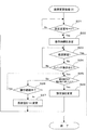
図3は、主制御基板50のCPU52により実行される設定変更処理(1)の手順を具体的に示している。先ずCPU52は、電源が投入されると主制御基板50の設定回路が設定変更モードにあるか否かを判断する(ステップS11)。設定変更モードに移行していなければ(ステップS11=No)、そのままCPU52はここで待機し、次の処理を実行することはない。なお、ステップS11の判断が否定(No)の場合はその時点で設定変更処理(1)を終了してもよい。
(3-1-1. Setting Change Processing 1)
FIG. 3 specifically shows the procedure of the setting change process (1) executed by the
これに対し、設定回路が設定変更モードにあると判断すると(ステップS11=Yes)、CPU52は次にステップS12に進み、現状の設定値が1段階繰り上がるのに要するリセットスイッチ86の操作回数を決定する。このときCPU52は、何ら規則性を持つことなくランダムに回数(例えば1〜10回程度)を決定し、この決定した回数を規定値としてRAMに保存する。
On the other hand, if it is determined that the setting circuit is in the setting change mode (step S11 = Yes), the
次にCPU52は変更後の設定値が確定されたか否かを判断する(ステップS13)。なお設定値の確定は、例えば始動レバー24の操作の有無によって判断することができ、この時点で未だ始動レバー24が操作されていなければ(ステップS13=No)、CPU52は次にステップS14に進む。
Next, the
ステップS14に進むとCPU52はリセットスイッチ86が操作されたか否かを判断する。リセットスイッチ86が操作されていない(ステップS14=No)間は、CPU52はステップS13,S14を繰り返しながらリセットスイッチ86の操作を待ち受ける。
In step S14, the
リセットスイッチ86が操作されると(ステップS14=Yes)、次にCPU52は操作回数が上記の規定値に達したか否かを判断する(ステップS15)。例えば、この時点でリセットスイッチ86の操作が1回であり、上記の規定値が2以上であるとすると、未だ操作回数が規定値に達していないため(ステップS15=No)、CPU52はステップS13に戻り、次にリセットスイッチ86が操作されるまでステップS13,S14を繰り返しながら待ち受け状態となる。
When the
この後、リセットスイッチ86の操作回数が規定値に達すると(ステップS15=Yes)、この時点でCPU52は設定値を変更する(ステップS16)。これにより、設定値は1段階繰り上げて変更され、表示部16に変更後の設定値が数値表示される。
Thereafter, when the number of operations of the
さらにCPU52は、設定値を変更するとステップS12に戻り、あらためて次の操作回数を決定する。ここでもまた、CPU52は操作回数をランダムに決定することができ、その決定した操作回数は新しく規定値としてRAMに保存される。
Further, when the set value is changed, the
この時点で始動レバー24が操作され、変更後の設定値が確定されると(ステップS13=Yes)、CPU52はここで設定変更処理(1)を終了する。これに対し、引き続きリセットスイッチ86が操作されると(ステップS14=Yes)、CPU52は操作回数が今回新たに決定した規定値に達したか否かを判断し(ステップS15)、操作回数が今回の規定値に達した時点でさらに設定値を変更する(ステップS16)。
At this time, when the
これ以降、設定値が確定されるまでCPU52はステップS12〜S16を繰り返し、この間、設定値が変更されるごとに次の操作回数をあらためて決定する。
Thereafter, the
上記のように設定変更処理(1)では、毎回の設定値の変更に要するリセットスイッチ86の操作回数がランダムに決定されるため、リセットスイッチ86の操作回数と設定値の繰り上げ段階数とが対応しなくなる。このため、不正遊技者が単純な接点ショート等の手口を用いて設定値の変更を試みたとしても、現状から狙ったとおりの設定値まで不正に変更を加えることはきわめて困難となる。
As described above, in the setting change process (1), the number of operations of the
(3−1−2.設定変更処理2)
上記の設定変更処理(1)では、リセットスイッチ86の操作回数をその操作時間に置き換えて判断することもできる。すなわちリセットスイッチ86について、その操作が継続してなされた時間の長短で設定値の変更をすべきか否かを判断するものである。
(3-1-2. Setting Change Process 2)
In the setting change process (1), the number of operations of the
図4は、設定変更処理(2)の手順を具体的に示している。ここでも同様に、CPU52は電源が投入されると主制御基板50の設定回路が設定変更モードにあるか否かを判断する(ステップS21)。このとき設定変更モードに移行していなければ(ステップS21=No)、そのままCPU52はここで待機し、次の処理を実行することはない。
FIG. 4 specifically shows the procedure of the setting change process (2). Similarly, when the power is turned on, the
次に設定回路が設定変更モードにあると判断すると(ステップS21=Yes)、CPU52はステップS22に進み、現状の設定値が1段階繰り上がるのに要するリセットスイッチ86の操作時間を決定する。このときCPU52は、何ら規則性を持つことなくランダムに操作時間(例えば1〜10秒間程度)を決定し、この決定した操作時間を規定時間としてRAMに保存する。
Next, when it is determined that the setting circuit is in the setting change mode (step S21 = Yes), the
次にCPU52は変更後の設定値が確定されたか否かを判断する(ステップS23)。この時点で未だ始動レバー24が操作されていなければ(ステップS23=No)、CPU52は次にステップS24に進む。
Next, the
ステップS24に進むとCPU52はリセットスイッチ86が操作されたか否かを判断する。リセットスイッチ86が操作されていない(ステップS24=No)間は、CPU52はステップS23,S24を繰り返しながらリセットスイッチ86の操作を待ち受ける。
In step S24, the
リセットスイッチ86が操作されると(ステップS24=Yes)、次にCPU52はその操作時間が上記の規定時間に達したか否かを判断する(ステップS25)。例えば、上記の規定時間が1秒間以上であるとすると、リセットスイッチ86が規定時間以上にわたって操作(押し込み操作)され続けていなければ(ステップS25=No)、CPU52は次にステップS26に進む。
When the
ステップS26では引き続きリセットスイッチ86の操作が継続されているか否かを判断し、操作が継続中であれば(Yes)、CPU52はステップS25に戻って操作時間の判断を繰り返す。
In step S26, it is determined whether or not the operation of the
これに対し、ステップS26においてリセットスイッチ86の操作が途切れたと判断すると(No)、CPU52はステップS27に進んで設定値を1に変更する。この結果、現状で設定値が2〜5であったとしても、リセットスイッチ86の操作時間が規定時間に満たなかった場合は全て、設定値が強制的に1に引き戻されることとなる。なお、現状で設定値が1であった場合、たとえステップS27で設定値が1に変更されたとしても見かけ上の設定値の変更はないが、それでも1段階上に繰り上がることなく現状以下に変更される結果となる。
On the other hand, if it is determined in step S26 that the operation of the
これに対し、リセットスイッチ86の操作時間が規定時間に達していると(ステップS25=Yes)、この時点でCPU52は設定値を変更する(ステップS26)。これにより、設定値は1段階繰り上げて変更され、表示部16に変更後の設定値が数値表示される。また、このとき作業者が設定値の変更を表示部16で確認すると、そこでリセットスイッチ86の操作を取りやめることができる。
On the other hand, when the operation time of the
さらにCPU52は、設定値を変更するとステップS22に戻り、あらためて次の操作時間を決定する。ここでもまた、CPU52は操作時間をランダムに決定することができ、その決定した操作時間は新しく規定時間としてRAMに保存される。なお、上記のステップS27で設定値が1に強制変更された場合も同様に、ステップS22に戻って新たに操作時間が決定される。
Further, when the setting value is changed, the
この時点で始動レバー24が操作され、変更後の設定値が確定されると(ステップS23=Yes)、CPU52はここで設定変更処理(2)を終了する。これに対し、また次にリセットスイッチ86が操作されると(ステップS24=Yes)、CPU52は操作時間が今回新たに決定した規定時間に達したか否かを判断し(ステップS25)、操作時間が今回の規定時間に達した時点でさらに設定値を変更する(ステップS26)。なお、規定時間に満たないままリセットスイッチ86の操作が途切れた場合は、CPU52は上記のようにステップS27に進んで設定値を強制的に1に変更する。
At this time, when the
これ以降、設定値が確定されるまでCPU52はステップS22〜S26を繰り返し、この間、設定値が変更されるごとに次の操作時間をあらためて決定する。
Thereafter, the
上記のように設定変更処理(2)では、毎回の設定値の変更に要するリセットスイッチ86の操作時間がランダムに決定される。この場合、単発的にリセットスイッチ86を操作しただけでは設定値の変更がなされないため、不正遊技者が単純な接点ショート等の手口を用いて設定値の変更を試みたとしても、現状から狙ったとおりの設定値まで不正に変更を加えることはきわめて困難となる。特に、リセットスイッチ86の接点ショート等によって1回だけパルス信号を発生させた場合、CPU52ではステップS27が実行されて、いつでも設定値が1に強制変更されてしまう。これにより、現状が比較的高い段階の設定値であったとしても、不正行為をはたらいたことが引き金となって設定値が1に逆戻りしてしまうため、不正遊技者が自ら不利益を被る結果を招くことになる。
As described above, in the setting change process (2), the operation time of the
(3−1−3.設定変更処理3)
図5は、設定変更処理(3)の手順を具体的に示している。ここでも同様に、CPU52は電源が投入されると主制御基板50の設定回路が設定変更モードにあるか否かを判断し、設定変更モードに移行していなければ(ステップS31=No)、そのままCPU52はここで待機する。
(3-1-3. Setting Change Process 3)
FIG. 5 specifically shows the procedure of the setting change process (3). Similarly, when the power is turned on, the
設定回路が設定変更モードに移行すると(ステップS31=Yes)、CPU52は次にステップS32に進み、ここで所定の設定変更テーブルを選択する。そして、CPU52は次に設定値が確定されたかを判断し(ステップS33)、未だ設定値が確定されていなければ(No)、リセットスイッチ86が操作されるまでステップS33,S34を繰り返す。リセットスイッチ86が操作されると(ステップS34=Yes)、CPU52はステップS32で選択した設定変更テーブルにしたがって設定値を決定する(ステップS35)。
When the setting circuit shifts to the setting change mode (step S31 = Yes), the
ここで、設定変更処理(3)で用いられる設定変更テーブルは、予め設定値の変更パターンを段階的にみて不規則に定めたテーブルデータであり、例えば以下のものが考えられる。 Here, the setting change table used in the setting change process (3) is table data that is irregularly determined in advance by stepwise changing the setting value change pattern. For example, the following can be considered.
図6は、設定変更テーブルとして利用できるテーブルデータの第1例を示している。このテーブルデータは、リセットスイッチ86の操作回数(何回目であるか)に対して予め1つの設定値(1〜6)を割り当てる変更パターンを記録したものであり、初期状態(操作回数0)において設定値を1とすると、この状態から操作回数が1回目,2回目,3回目,・・・・と変遷していくと、それぞれの操作回数ごとに予め決められた設定値が割り当てられる。 FIG. 6 shows a first example of table data that can be used as a setting change table. This table data records a change pattern in which one set value (1 to 6) is assigned in advance to the number of operations of the reset switch 86 (how many times), and in the initial state (number of operations 0). Assuming that the set value is 1, when the number of operations changes from this state to the first, second, third,..., A preset set value is assigned for each operation count.
設定変更処理(3)において図6のテーブルデータを用いた場合、例えば操作回数が1〜2回目まで設定値は1のままであり、操作回数が3回目でようやく設定値は2に繰り上がる。ところが、操作回数が4回目になると設定値は1に逆戻りとなり、この後さらに6回目まで設定値は1のまま維持される。操作回数が7回目になると2段階飛んで設定値が1から3に跳ね上がるが、次の8回目でまた設定値は1に逆戻りする。 When the table data of FIG. 6 is used in the setting change process (3), for example, the setting value remains 1 until the number of operations is 1-2, and the setting value is finally incremented to 2 when the number of operations is the third. However, when the number of operations reaches the fourth time, the set value returns to 1, and thereafter, the set value is maintained at 1 until the sixth time. When the number of operations reaches the seventh time, the setting value jumps from 1 to 3 by two steps, but at the next eighth time, the setting value returns to 1 again.
以下同様に、ある操作回数まで到達すると設定値は1から飛んで4〜6に直接跳ね上がるが、次の操作回数で設定値は1に逆戻りし、さらに設定値1の状態が数回続くものとなっている。このように、図6のテーブルデータではリセットスイッチ86の全操作回数に対して設定値が1となる場合が最も多く、設定値が1より上の段階に変更される機会は相対的に少ない。
Similarly, when a certain number of operations is reached, the set value jumps from 1 and jumps directly to 4-6, but at the next number of operations, the set value returns to 1, and the state of the
次に図7は、テーブルデータの第2例を示している。このテーブルデータもまた、リセットスイッチ86の操作回数(何回目であるか)に対して予め1つの設定値(1〜6)を割り当てる変更パターンを記録したものであるが、ここでは操作回数が増えるにしたがって不規則な階段状に設定値が繰り上げられていくものとなっている。 Next, FIG. 7 shows a second example of table data. This table data also records a change pattern in which one set value (1 to 6) is assigned in advance to the number of operations of the reset switch 86 (how many times), but here the number of operations increases. The set value is raised in an irregular step shape.
すなわち、初期状態(操作回数=0)で設定値が1であるとすると、操作回数が1〜3回目まで設定値は1のまま不変であり、操作回数が4回目になってようやく設定値が2に繰り上がる。次にリセットスイッチ86が操作されても設定値は2のまま不変であり、操作回数が6回目になって設定値が3に繰り上がる。以下同様に、設定値が3から4に繰り上がるまでの操作回数は1回であるが、設定値が4から5、5から6へそれぞれ繰り上がるまでの操作回数は2回である。
That is, if the setting value is 1 in the initial state (number of operations = 0), the setting value remains unchanged from 1 to the number of
設定変更処理(3)において図7のテーブルデータを用いた場合、設定値は1から順番に繰り上がっていくが、次の段階へ繰り上がるまでに要する操作回数は不定となる。したがって、図7のテーブルデータを用いた場合は先に説明した設定変更処理(1)と同じような結果が得られる。 When the table data of FIG. 7 is used in the setting change process (3), the set value is incremented in order from 1, but the number of operations required to advance to the next stage is indefinite. Therefore, when the table data of FIG. 7 is used, a result similar to the setting change process (1) described above is obtained.
いずれにしても、CPU52はリセットスイッチ86が操作されるごとに、その操作回数(何回目であるか)に対応する設定値を設定変更テーブルから決定する(ステップS35)。このとき、リセットスイッチ86の操作前後で常に設定値が変更されるとは限らず、リセットスイッチ86が操作されても設定値が変わらない場合もある。なお、このとき表示部16にあらためて設定値が数値表示されるので、作業者は目的とする設定値に変わるまでリセットスイッチ86を何回か操作することとなる。
In any case, every time the
所望の設定値に変わった時点で始動レバー24が操作され、変更後の設定値が確定されると(ステップS33=Yes)、CPU52はここで設定変更処理(3)を終了する。これに対し、引き続きリセットスイッチ86が操作されると(ステップS34=Yes)、CPU52はあらためて設定変更テーブルから次の操作回数に対応する設定値を決定する(ステップS35)。これ以降、設定値が確定されるまでCPU52はステップS33〜S35の手順を繰り返す。
When the
上記のように設定変更処理(3)では、リセットスイッチ86の操作回数(何回目であるか)にそれぞれ対応して予め設定値が割り当てられているため、単純に操作回数と設定値の繰り上げ変更とは対応しないこととなる。
As described above, in the setting change process (3), setting values are assigned in advance corresponding to the number of operations (how many times) the
特に、図6のテーブルデータではリセットスイッチ86の全操作回数に対して設定値が1となる場合が最も多く、設定値が1より上の段階に変更される機会は相対的に少ない。このため、不正遊技者が単純な接点ショート等の手口を用いて設定値の変更を試みたとしても、現状から狙ったとおりの段階まで不正に設定値を変更することはきわめて困難であるし、さらに設定値を1以外に変更することは確率的にも難しくなる。このことは逆にいえば、現状で比較的高い段階の設定値であったにもかかわらず、不正操作によって設定値が1に逆戻りしてしまう確率が高いため、不正行為をはたらくことによって自ら不利な状況を招きやすくなる。
In particular, in the table data of FIG. 6, the setting value is most often 1 with respect to the total number of operations of the
(3−2.第2の方法論)
次に第2の方法論として、設定変更の際にスイッチ操作で目的とする設定値に直接変更するものを取り上げる。
(3-2. Second methodology)
Next, a second methodology will be described in which the setting value is changed directly to a target setting value by operating a switch when the setting is changed.
第1の方法論ではリセットスイッチ86の操作によって接点信号を生成し、これを主制御基板50で受信して操作回数や操作時間をカウントして設定値の変更を行っていたが、第2の方法論では設定値を表す識別信号を生成し、これを主制御基板50で解読することで所望の設定値に直接変更するものである。
In the first methodology, a contact point signal is generated by operating the
図8は、第2の方法論を実現するための一構成例を概略的に示している。この場合、電源ボックス80には複数のコードスイッチ90a,90b,90cが配設されており、これらコードスイッチ90a,90b,90cには、1から6までの設定値を表すコード信号が割り当てられている。なお、図8の構成例では3つのコードスイッチ90a,90b,90cが設けられており、これらのONまたはOFFの組み合わせによって6通りのコード信号が生成されるものとなっている。
FIG. 8 schematically shows a configuration example for realizing the second methodology. In this case, the
例えば、設定値1〜3を表すコード信号は、それぞれコードスイッチ90a,90b,90cに単独で割り当てられている。設定値4を表すコード信号は、例えばコードスイッチ90a,90bの2つの組み合わせに割り当てられている。また設定値5を表すコード信号は、例えばコードスイッチ90b,90cの2つの組み合わせに割り当てられている。そして設定値6を表すコード信号は、3つのコードスイッチ90a,90b,90cの3つの組み合わせに割り当てられている。なお、電源ボックス80には1から6の設定値にそれぞれ対応するべく6つのコードスイッチが設けられていてもよい。
For example, the code signals representing the setting values 1 to 3 are individually assigned to the
(3−2−1.設定変更処理4)
図9は、CPU52により実行される設定変更処理(4)の手順を具体的に示している。
ここでも同様に、CPU52は電源が投入されると主制御基板50の設定回路が設定変更モードにあるか否かを判断する(ステップS41)。設定変更モードに移行していなければ(ステップS41=No)、そのままCPU52はここで待機する。なお、ステップS41の判断が否定(No)の場合はその時点で設定変更処理(4)を終了してもよい。
(3-2-1. Setting Change Process 4)
FIG. 9 specifically shows the procedure of the setting change process (4) executed by the
Similarly, when the power is turned on, the
これに対し、設定回路が設定変更モードにあると判断すると(ステップS41=Yes)、CPU52は次にステップS42に進み、ここで設定値が確定されたか否かを判断する。この時点で未だ始動レバー24が操作されていなければ(ステップS42=No)、CPU52は次にステップS43に進む。
On the other hand, when it is determined that the setting circuit is in the setting change mode (step S41 = Yes), the
ステップS43に進むとCPU52はコード信号が変更されたか否かを判断する。例えば現状で設定値が1であれば、これを表すコード信号が電源ボックス80から主制御基板50に送信されているが、特にコードスイッチ90が操作されていなければ、この時点でコード信号に変更はない。したがってCPU52は、コード信号に変更がない(ステップS43=No)間はステップS42,S43を繰り返しながらコードスイッチ90の操作を待ち受ける。
In step S43, the
設定値を変更するべくコードスイッチ90が操作されると、それまでとは異なるコード信号が生成されて主制御基板50に送信されるため、CPU52はコード信号が変更されたと判断し(ステップS43=Yes)、この時点でコード信号により表される段階に設定値を直接変更する(ステップS44)。またこれにより、表示部16に変更後の設定値が数値表示される。
When the
さらにCPU52は、設定値を変更するとステップS42に戻り、ここで設定値が確定されたか否かを判断する。この時点で始動レバー24が操作され、変更後の設定値が確定されると(ステップS42=Yes)、CPU52はここで設定変更処理(4)を終了する。これに対し、引き続きコードスイッチ90が操作されてコード信号に変更があると(ステップS43=Yes)、CPU52はさらに変更後のコード信号により表される段階に設定値を直接変更する(ステップS44)。これ以降、設定値が確定されるまでCPU52はステップS42〜S44を繰り返す。
Further, when the set value is changed, the
上記のように設定変更処理(4)では、設定変更の際にコード信号とコードスイッチ90a〜90cの操作との組み合わせが成立してはじめて設定値の変更が行われる。例えば、設定変更の際に目的とする設定値(例えば6)があったとしても、その段階を表すコード信号は適切なコードスイッチ90a〜90cを組み合わせて操作しない限り生成されない。このため、でたらめにコードスイッチ90a〜90cを操作しただけでは所望の設定値に変更することができず、設定変更の方法論としてより高度化されたものであるといえる。
As described above, in the setting change process (4), the setting value is changed only after the combination of the code signal and the operation of the code switches 90a to 90c is established at the time of changing the setting. For example, even if there is a target setting value (for example, 6) at the time of changing the setting, a code signal representing that stage is not generated unless the
この場合、たとえ不正遊技者が単純な接点ショート等による設定変更を試みたところでコード信号を生成させることは到底できないため、不正行為による設定変更への介入は技術的にも困難を極める。 In this case, since it is impossible to generate a code signal when an unauthorized player attempts to change the setting by a simple contact short-circuit or the like, it is technically difficult to intervene in the setting change due to an illegal act.
(4.付加的要素の説明)
上記のように、本実施形態では第1および第2の方法論のいずれによっても不正な設定変更を強力にブロックすることができるが、合わせて以下の手法を採用することでより強固な不正対策を施すことができる。
(4. Explanation of additional elements)
As described above, in this embodiment, unauthorized setting changes can be strongly blocked by both the first and second methodologies. However, by adopting the following method, a more robust countermeasure against fraud can be achieved. Can be applied.
(4−1.インターロック処理)
図10は、主制御基板50のCPU52により実行されるインターロック処理の手順を具体的に示している。このインターロック処理は、スロットマシン1の前面扉4が開放されているか否かによって設定値の表示または非表示、通常設定変更またはランダム設定変更をそれぞれ使い分けるものである。
(4-1. Interlock processing)
FIG. 10 specifically shows the procedure of the interlock process executed by the
ここでも同様に、CPU52は電源投入後にインターロック処理を開始すると、設定回路が設定変更モードにあるか否かを判断し(ステップS51)、設定変更モードに移行している場合(Yes)はこれ以降の手順に進む。
Similarly, when the
次にCPU52は、スロットマシン1の前面扉4が開放されているか否かを判断する(ステップS52)。ここでの判断には、例えばスロットマシン1に付属する扉開放スイッチ92(図2に示されている)を用いることができる。CPU52は扉開放スイッチ92からの検出信号に基づいて前面扉4が開放されているか否かを判断し、前面扉4が開放中の場合(Yes)は以下のステップS53,S54を実行してインターロック処理を終了する。逆に、前面扉4が開放されていない場合(No)は別のステップS55,S56を実行してインターロック処理を終了する。
Next, the
これにより、例えば遊技場運営者の管理下で正規に設定値の変更を行う場合、通常は専用の扉キーを用いて前面扉4が開かれていると考えられる。この場合はCPU52によりステップS53,S54が実行されるため、設定変更モードに移行すると表示部16に現状の設定値が数値表示される(表示許可手段)とともに、通常設定変更の態様で設定値を変更することが可能となる。なお、ここでいう「通常設定変更」とは、例えばリセットスイッチ86が操作されるごとに1段階ずつ設定値が繰り上がっていく態様である。このため、正規に設定値の変更を行う場合はその作業が容易であり、遊技場運営者にとって利便である。
Thereby, for example, when the set value is regularly changed under the management of the game hall operator, it is considered that the
これに対し、不正行為によって設定変更への介入がなされる場合、前面扉4は施錠された状態にある。このような状態で不正行為によって設定変更モードに移行された場合、CPU52によりステップS55が実行されるため表示部16に設定値が数値表示されず、不正遊技者に現状の設定値に関する情報を具体的に盗み取られることはない。
On the other hand, when the intervention to the setting change is performed by an illegal act, the
また、あわせてステップS56が実行されるため、この場合はランダム設定変更の態様でしか設定値を変更することができなくなる。ここでいう「ランダム設定変更」とは、例えば上記の設定変更処理(1)〜(4)による不規則な設定値の変更態様である。これにより、不正行為が行われた場合だけ選択的に設定変更ロジックを複雑化することができるので、不正な設定変更を有効に防止することができる。 Further, since step S56 is also executed, in this case, the set value can be changed only in a random setting change mode. The “random setting change” here is an irregular setting value change mode by the setting change processes (1) to (4), for example. This makes it possible to selectively complicate the setting change logic only when an illegal act is performed, so that it is possible to effectively prevent an illegal setting change.
(5.その他の実施形態についての言及)
本発明の遊技機は、一実施形態のみに制約されず、その他の形態による実施の可能性がある。以下に、その他の実施形態についていくつか例を挙げて言及する。
(5. Reference to other embodiments)
The gaming machine of the present invention is not limited to one embodiment, and may be implemented in other forms. In the following, other embodiments will be described with some examples.
(1)一実施形態では主制御基板50に確率の設定を行う設定回路が組み込まれているが、設定回路は主制御基板50とは別に設けられていてもよい。
(2)一実施形態では設定値の変更操作を行うためのスイッチとして、リセットスイッチ86が例示されているが、これとは別に専用のスイッチが設けられていてもよい。
(1) In one embodiment, a setting circuit for setting a probability is incorporated in the
(2) In one embodiment, the
(3)設定変更処理(1)のステップS12では毎回ランダムに操作回数を決定するようにしているが、操作回数は固定値であってもよい。あるいは、ステップS12の前に操作回数をランダムに決定するか否かの抽選を行い、その結果に応じてステップS12を実行するか否かを決定するようにしてもよい。
(4)また設定変更処理(2)のステップS22では毎回ランダムに操作時間を決定するようにしているが、操作時間は一定であってもよい。あるいは、ステップS22の前に操作時間をランダムに決定するか否かの抽選を行い、その結果に応じてステップS22を実行するか否かを決定するようにしてもよい。
(3) In step S12 of the setting change process (1), the number of operations is determined randomly every time, but the number of operations may be a fixed value. Alternatively, it may be determined whether or not to randomly determine the number of operations before step S12, and whether or not to execute step S12 according to the result may be determined.
(4) In step S22 of the setting change process (2), the operation time is determined randomly every time, but the operation time may be constant. Alternatively, it may be determined whether or not to randomly determine the operation time before step S22, and whether or not to execute step S22 according to the result may be determined.
(5)設定変更処理(2)のステップS27では常に設定値を1に強制的に変更するようにしているが、現状の設定値が2以上の段階である場合、現状を含むそれ以下の段階に変更するようにしてもよい。 (5) The setting value is always forcibly changed to 1 in step S27 of the setting change process (2). However, if the current setting value is 2 or more, the following stages including the current state are included. You may make it change to.
(6)設定変更処理(3)で用いられる設定変更テーブルは図6,図7の例に限られず、その他のものであってもよい。また、図6,図7のテーブルデータでは設定値が1〜6まで変更される順序を表す変更パターンが1通りだけ示されているが、各テーブルデータには2通り以上の変更パターンを予め記録しておくこともできる。 (6) The setting change table used in the setting change process (3) is not limited to the examples of FIGS. 6 and 7 and may be other types. In addition, in the table data of FIGS. 6 and 7, only one change pattern indicating the order in which the set values are changed from 1 to 6 is shown, but two or more change patterns are recorded in advance in each table data. You can also keep it.
(7)また本発明においては、たとえ不正行為による設定変更が未遂に終わったとしても、何らかの不正行為があった場合に以下のように有効な対策を施すことができる。 (7) Further, in the present invention, even if the setting change due to the fraud is unsuccessful, the following effective measures can be taken if there is any fraud.
例えば設定変更処理(1)〜(4)の実行に際し、設定回路が設定変更モードに移行された時から所定のタイマーをセット(起動)し、所定時間内に設定変更操作がなされなければタイムオーバーとして各設定変更処理を強制的に終了させるようにしてもよい。その場合、設定値を変更するスイッチ操作のみがあって、設定値を確定させる操作がなければ、タイムオーバーとなった時点で強制的に設定を確定させるような処理内容であってもよいし、あるいは、全ての変更操作を無効として強制的に従前の設定値に引き戻すような処理内容であってもよい。 For example, when executing the setting change processing (1) to (4), a predetermined timer is set (started) from the time when the setting circuit shifts to the setting change mode, and if the setting change operation is not performed within the predetermined time, the time is over. Each setting change process may be forcibly terminated. In that case, if there is only a switch operation for changing the setting value and there is no operation for confirming the setting value, the processing content may forcibly confirm the setting when the time is over, or The processing content may be such that all the change operations are invalidated and forcibly returned to the previous set values.
また設定変更の操作が正しく行われなかったとき、例えば設定変更処理(1),(2)においてスイッチの操作回数または操作時間が上記の規定回数や規定時間に満たなかった場合や、設定変更処理(4)においてコード信号ではなくパルス信号のみが設定回路に入力された場合のように正規の態様で設定変更操作が行われなかったとき、CPUが不正操作の可能性があると判断してアラームを発するようにしてもよい。この場合には遊技機に付属のスピーカから警報音を発したり、特定のランプを点灯・点滅させたりして周囲に不正行為を報知してもよいし、あるいは、その場で特に不正行為を報知せずに外部端子基板を通じてホールコンピュータに警報信号を送信させるだけでもよい。 Further, when the setting change operation is not performed correctly, for example, in the setting change processing (1), (2), when the number of switch operations or the operation time does not reach the specified number of times or specified time, When the setting change operation is not performed in a normal manner as in the case where only the pulse signal instead of the code signal is input to the setting circuit in (4), the CPU determines that there is a possibility of an unauthorized operation and alarms May be issued. In this case, a warning sound may be emitted from the speaker attached to the gaming machine, a specific lamp may be turned on or blinking to notify the misconduct to the surroundings, or an improper act will be particularly noticed on the spot. Instead, the alarm signal may be transmitted to the hall computer through the external terminal board.
(8)インターロック処理は、第1および第2の方法論のいずれについても付加的に適用可能である。また、図10ではステップS53,S54やステップS55,S56がセットで実行されるものとなっているが、いずれか一方のみが実行される態様であってもよい。例えば、図10のインターロック処理を2つのフローチャートに分割し、一方のフローチャートではステップS52に続いてステップS53またはステップS55が実行されるものとし、他方のフローチャートではステップS52に続いてステップS54またはステップS56が実行されるものとすることができる。 (8) The interlock process can be additionally applied to both the first and second methodologies. In FIG. 10, steps S53 and S54 and steps S55 and S56 are executed as a set, but only one of them may be executed. For example, the interlock process of FIG. 10 is divided into two flowcharts. In one flowchart, step S53 or step S55 is executed following step S52, and in the other flowchart, step S54 or step is executed following step S52. S56 may be executed.
(9)また、例えば設定変更処理(1)〜(3)ではリセットスイッチ86を押し込む操作によって主制御基板50に接点信号が送信されるものとなっているが、これに代えて設定キースイッチ84のひねり操作によって操作回数や操作時間のカウントを行うようにしてもよい。
(9) Further, for example, in the setting change processing (1) to (3), a contact signal is transmitted to the
(10)あるいは、第1の方法論においてリセットスイッチ86が操作され続けている間にCPU52において例えば1〜6までの乱数を発生させ、リセットスイッチ86の操作が途切れた時点で乱数を取得し、そのときの乱数値から設定値を変更する態様であってもよい。
(10) Alternatively, the
(11)既に述べたように、抽選確率の設定とその変更が可能な仕様を有する遊技機はスロットマシンに限らず、CR機タイプのパチンコ機であってもよい。
(12)その他、一実施形態で挙げたスロットマシンの構成はあくまで好ましい例示であり、これらは適宜変更可能であることはいうまでもない。
(11) As already described, a gaming machine having a specification that allows setting and changing the lottery probability is not limited to a slot machine, but may be a CR machine type pachinko machine.
(12) In addition, the configuration of the slot machine described in the embodiment is merely a preferable example, and it is needless to say that these can be changed as appropriate.
1 スロットマシン
2 筐体(遊技機本体)
4 前面扉(扉部材)
16 表示部(表示手段)
50 主制御基板
82 電源スイッチ
84 設定キースイッチ
86 リセットスイッチ
90 コードスイッチ
92 扉開放スイッチ(開閉状態検出手段)
1
4 Front door (door member)
16 Display section (display means)
50
Claims (1)
前記抽選に当る確率を段階的に設定し、この設定の段階を表す設定値に対応して前記確率の高低度合いを異ならせる設定回路と、
前記設定回路に接続されたスイッチを有し、このスイッチに対する操作に応じて前記設定値を変更させる設定変更手段とを具備したことを特徴とする遊技機。 In a gaming machine that performs a lottery in accordance with a game operation by a player and gives a predetermined prize bonus to the player when the lottery is won,
A setting circuit that sets the probability of winning the lottery step by step, and changes the level of the probability according to a setting value that represents the stage of the setting;
A gaming machine comprising a switch connected to the setting circuit, and setting changing means for changing the set value in accordance with an operation on the switch.
Priority Applications (1)
| Application Number | Priority Date | Filing Date | Title |
|---|---|---|---|
| JP2003358985A JP2005118417A (en) | 2003-10-20 | 2003-10-20 | Game machine |
Applications Claiming Priority (1)
| Application Number | Priority Date | Filing Date | Title |
|---|---|---|---|
| JP2003358985A JP2005118417A (en) | 2003-10-20 | 2003-10-20 | Game machine |
Related Child Applications (4)
| Application Number | Title | Priority Date | Filing Date |
|---|---|---|---|
| JP2008304070A Division JP4701283B2 (en) | 2008-11-28 | 2008-11-28 | Game machine |
| JP2008304073A Division JP4757295B2 (en) | 2008-11-28 | 2008-11-28 | Game machine |
| JP2008304072A Division JP4701285B2 (en) | 2008-11-28 | 2008-11-28 | Game machine |
| JP2008304071A Division JP4701284B2 (en) | 2008-11-28 | 2008-11-28 | Game machine |
Publications (2)
| Publication Number | Publication Date |
|---|---|
| JP2005118417A true JP2005118417A (en) | 2005-05-12 |
| JP2005118417A5 JP2005118417A5 (en) | 2008-10-16 |
Family
ID=34615353
Family Applications (1)
| Application Number | Title | Priority Date | Filing Date |
|---|---|---|---|
| JP2003358985A Pending JP2005118417A (en) | 2003-10-20 | 2003-10-20 | Game machine |
Country Status (1)
| Country | Link |
|---|---|
| JP (1) | JP2005118417A (en) |
Cited By (18)
| Publication number | Priority date | Publication date | Assignee | Title |
|---|---|---|---|---|
| JP2007068582A (en) * | 2005-09-02 | 2007-03-22 | Olympia:Kk | Game machine |
| JP2007209381A (en) * | 2006-02-07 | 2007-08-23 | Olympia:Kk | Game machine |
| JP2008067825A (en) * | 2006-09-13 | 2008-03-27 | Olympia:Kk | Game machine and game machine system |
| JP2008142126A (en) * | 2006-12-06 | 2008-06-26 | Samii Kk | Game machine |
| JP2008237485A (en) * | 2007-03-27 | 2008-10-09 | Olympia:Kk | Game machine |
| JP2008295873A (en) * | 2007-06-01 | 2008-12-11 | Daito Giken:Kk | Game machine |
| JP2009011537A (en) * | 2007-07-04 | 2009-01-22 | Samii Kk | Game machine |
| JP2009011538A (en) * | 2007-07-04 | 2009-01-22 | Samii Kk | Game machine |
| JP2013042870A (en) * | 2011-08-23 | 2013-03-04 | Sankyo Co Ltd | Game machine |
| JP2014230998A (en) * | 2014-08-22 | 2014-12-11 | 株式会社三共 | Game machine |
| JP2014230997A (en) * | 2014-08-22 | 2014-12-11 | 株式会社三共 | Game machine |
| JP2015024201A (en) * | 2014-10-23 | 2015-02-05 | 株式会社三共 | Game machine |
| JP2015024202A (en) * | 2014-10-23 | 2015-02-05 | 株式会社三共 | Game machine |
| JP2016104460A (en) * | 2016-03-11 | 2016-06-09 | 株式会社三共 | Game machine |
| JP2016104461A (en) * | 2016-03-11 | 2016-06-09 | 株式会社三共 | Game machine |
| JP2019072383A (en) * | 2017-10-19 | 2019-05-16 | 株式会社サンセイアールアンドディ | Game machine |
| JP2019208673A (en) * | 2018-05-31 | 2019-12-12 | 株式会社サンセイアールアンドディ | Game machine |
| JP2020010990A (en) * | 2018-07-20 | 2020-01-23 | 株式会社ソフイア | Game machine |
Citations (7)
| Publication number | Priority date | Publication date | Assignee | Title |
|---|---|---|---|---|
| JPH08206292A (en) * | 1995-11-06 | 1996-08-13 | Sankyo Kk | Pachinko game machine |
| JPH10323443A (en) * | 1997-05-26 | 1998-12-08 | Sansei:Kk | Hit probability change-over device for pachinko game machine |
| JP2000296200A (en) * | 1999-02-12 | 2000-10-24 | Sankyo Kk | Slot machine |
| JP2003010381A (en) * | 2001-06-27 | 2003-01-14 | Sankyo Kk | Slot machine |
| JP2003052887A (en) * | 2001-08-09 | 2003-02-25 | Fuji Shoji:Kk | Game machine |
| JP2003180942A (en) * | 2001-12-17 | 2003-07-02 | Olympia:Kk | Game machine, program, and storage medium |
| JP2003245402A (en) * | 2002-02-25 | 2003-09-02 | Aruze Corp | Game machine setting value abnormality alarm |
-
2003
- 2003-10-20 JP JP2003358985A patent/JP2005118417A/en active Pending
Patent Citations (7)
| Publication number | Priority date | Publication date | Assignee | Title |
|---|---|---|---|---|
| JPH08206292A (en) * | 1995-11-06 | 1996-08-13 | Sankyo Kk | Pachinko game machine |
| JPH10323443A (en) * | 1997-05-26 | 1998-12-08 | Sansei:Kk | Hit probability change-over device for pachinko game machine |
| JP2000296200A (en) * | 1999-02-12 | 2000-10-24 | Sankyo Kk | Slot machine |
| JP2003010381A (en) * | 2001-06-27 | 2003-01-14 | Sankyo Kk | Slot machine |
| JP2003052887A (en) * | 2001-08-09 | 2003-02-25 | Fuji Shoji:Kk | Game machine |
| JP2003180942A (en) * | 2001-12-17 | 2003-07-02 | Olympia:Kk | Game machine, program, and storage medium |
| JP2003245402A (en) * | 2002-02-25 | 2003-09-02 | Aruze Corp | Game machine setting value abnormality alarm |
Cited By (19)
| Publication number | Priority date | Publication date | Assignee | Title |
|---|---|---|---|---|
| JP2007068582A (en) * | 2005-09-02 | 2007-03-22 | Olympia:Kk | Game machine |
| JP2007209381A (en) * | 2006-02-07 | 2007-08-23 | Olympia:Kk | Game machine |
| JP2008067825A (en) * | 2006-09-13 | 2008-03-27 | Olympia:Kk | Game machine and game machine system |
| JP2008142126A (en) * | 2006-12-06 | 2008-06-26 | Samii Kk | Game machine |
| JP2008237485A (en) * | 2007-03-27 | 2008-10-09 | Olympia:Kk | Game machine |
| JP2008295873A (en) * | 2007-06-01 | 2008-12-11 | Daito Giken:Kk | Game machine |
| JP2009011537A (en) * | 2007-07-04 | 2009-01-22 | Samii Kk | Game machine |
| JP2009011538A (en) * | 2007-07-04 | 2009-01-22 | Samii Kk | Game machine |
| JP2013042870A (en) * | 2011-08-23 | 2013-03-04 | Sankyo Co Ltd | Game machine |
| JP2014230998A (en) * | 2014-08-22 | 2014-12-11 | 株式会社三共 | Game machine |
| JP2014230997A (en) * | 2014-08-22 | 2014-12-11 | 株式会社三共 | Game machine |
| JP2015024201A (en) * | 2014-10-23 | 2015-02-05 | 株式会社三共 | Game machine |
| JP2015024202A (en) * | 2014-10-23 | 2015-02-05 | 株式会社三共 | Game machine |
| JP2016104460A (en) * | 2016-03-11 | 2016-06-09 | 株式会社三共 | Game machine |
| JP2016104461A (en) * | 2016-03-11 | 2016-06-09 | 株式会社三共 | Game machine |
| JP2019072383A (en) * | 2017-10-19 | 2019-05-16 | 株式会社サンセイアールアンドディ | Game machine |
| JP2019208673A (en) * | 2018-05-31 | 2019-12-12 | 株式会社サンセイアールアンドディ | Game machine |
| JP7054190B2 (en) | 2018-05-31 | 2022-04-13 | 株式会社サンセイアールアンドディ | Pachinko machine |
| JP2020010990A (en) * | 2018-07-20 | 2020-01-23 | 株式会社ソフイア | Game machine |
Similar Documents
| Publication | Publication Date | Title |
|---|---|---|
| JP2005118417A (en) | Game machine | |
| JP2011072558A (en) | Game machine | |
| JP2004049513A (en) | Slot machine and game control method for the slot machine | |
| JP4757295B2 (en) | Game machine | |
| JP2020103780A (en) | Game machine | |
| JP2004350807A (en) | Game machine | |
| JP2004290594A (en) | Game machine | |
| JP2006191998A (en) | Game machine and its set value display device | |
| JP2020103779A (en) | Game machine | |
| JP4701285B2 (en) | Game machine | |
| JP4701283B2 (en) | Game machine | |
| JP4701284B2 (en) | Game machine | |
| JP5376432B2 (en) | Game machine | |
| JP2006255179A (en) | Game management system | |
| JP2007181535A (en) | Game machine | |
| JP2020103766A (en) | Game machine | |
| JP2020103767A (en) | Game machine | |
| JP2020103777A (en) | Game machine | |
| JP2020103765A (en) | Game machine | |
| JP2020103758A (en) | Game machine | |
| JP5467448B2 (en) | Game machine | |
| JP4575850B2 (en) | Game machine | |
| JP2020103774A (en) | Game machine | |
| JP2020103776A (en) | Game machine | |
| JP2020103773A (en) | Game machine |
Legal Events
| Date | Code | Title | Description |
|---|---|---|---|
| A621 | Written request for application examination |
Free format text: JAPANESE INTERMEDIATE CODE: A621 Effective date: 20050914 |
|
| RD04 | Notification of resignation of power of attorney |
Free format text: JAPANESE INTERMEDIATE CODE: A7424 Effective date: 20071221 |
|
| A521 | Written amendment |
Free format text: JAPANESE INTERMEDIATE CODE: A523 Effective date: 20080902 |
|
| A977 | Report on retrieval |
Free format text: JAPANESE INTERMEDIATE CODE: A971007 Effective date: 20080917 |
|
| A131 | Notification of reasons for refusal |
Free format text: JAPANESE INTERMEDIATE CODE: A131 Effective date: 20080930 |
|
| A521 | Written amendment |
Free format text: JAPANESE INTERMEDIATE CODE: A523 Effective date: 20081128 |
|
| A131 | Notification of reasons for refusal |
Free format text: JAPANESE INTERMEDIATE CODE: A131 Effective date: 20090224 |
|
| A711 | Notification of change in applicant |
Free format text: JAPANESE INTERMEDIATE CODE: A712 Effective date: 20090316 |
|
| A521 | Written amendment |
Free format text: JAPANESE INTERMEDIATE CODE: A523 Effective date: 20090427 |
|
| A02 | Decision of refusal |
Free format text: JAPANESE INTERMEDIATE CODE: A02 Effective date: 20090623 |
|
| A521 | Written amendment |
Free format text: JAPANESE INTERMEDIATE CODE: A523 Effective date: 20090924 |
|
| RD02 | Notification of acceptance of power of attorney |
Free format text: JAPANESE INTERMEDIATE CODE: A7422 Effective date: 20090924 |
|
| A521 | Written amendment |
Free format text: JAPANESE INTERMEDIATE CODE: A523 Effective date: 20091007 |
|
| A521 | Written amendment |
Free format text: JAPANESE INTERMEDIATE CODE: A523 Effective date: 20091006 |
|
| A911 | Transfer of reconsideration by examiner before appeal (zenchi) |
Free format text: JAPANESE INTERMEDIATE CODE: A911 Effective date: 20091102 |
|
| A912 | Removal of reconsideration by examiner before appeal (zenchi) |
Free format text: JAPANESE INTERMEDIATE CODE: A912 Effective date: 20091204 |