JP2005073796A - Game machine - Google Patents
Game machine Download PDFInfo
- Publication number
- JP2005073796A JP2005073796A JP2003305550A JP2003305550A JP2005073796A JP 2005073796 A JP2005073796 A JP 2005073796A JP 2003305550 A JP2003305550 A JP 2003305550A JP 2003305550 A JP2003305550 A JP 2003305550A JP 2005073796 A JP2005073796 A JP 2005073796A
- Authority
- JP
- Japan
- Prior art keywords
- internal winning
- winning combination
- stop
- symbol
- player
- Prior art date
- Legal status (The legal status is an assumption and is not a legal conclusion. Google has not performed a legal analysis and makes no representation as to the accuracy of the status listed.)
- Pending
Links
- 239000004973 liquid crystal related substance Substances 0.000 abstract description 58
- 238000000034 method Methods 0.000 abstract description 54
- 238000012545 processing Methods 0.000 abstract description 9
- 241000167854 Bourreria succulenta Species 0.000 description 64
- 235000019693 cherries Nutrition 0.000 description 64
- 230000000694 effects Effects 0.000 description 56
- 241000219109 Citrullus Species 0.000 description 25
- 235000012828 Citrullus lanatus var citroides Nutrition 0.000 description 25
- 238000005070 sampling Methods 0.000 description 11
- 239000010408 film Substances 0.000 description 6
- PZTQVMXMKVTIRC-UHFFFAOYSA-L chembl2028348 Chemical compound [Ca+2].[O-]S(=O)(=O)C1=CC(C)=CC=C1N=NC1=C(O)C(C([O-])=O)=CC2=CC=CC=C12 PZTQVMXMKVTIRC-UHFFFAOYSA-L 0.000 description 5
- 238000001514 detection method Methods 0.000 description 5
- 239000000779 smoke Substances 0.000 description 5
- 238000004891 communication Methods 0.000 description 4
- 238000010586 diagram Methods 0.000 description 4
- 239000011521 glass Substances 0.000 description 4
- 230000002093 peripheral effect Effects 0.000 description 4
- 238000003825 pressing Methods 0.000 description 4
- 238000003860 storage Methods 0.000 description 4
- 239000000758 substrate Substances 0.000 description 4
- 238000003780 insertion Methods 0.000 description 3
- 230000037431 insertion Effects 0.000 description 3
- NJPPVKZQTLUDBO-UHFFFAOYSA-N novaluron Chemical group C1=C(Cl)C(OC(F)(F)C(OC(F)(F)F)F)=CC=C1NC(=O)NC(=O)C1=C(F)C=CC=C1F NJPPVKZQTLUDBO-UHFFFAOYSA-N 0.000 description 3
- 230000001681 protective effect Effects 0.000 description 3
- 238000013461 design Methods 0.000 description 2
- 238000011161 development Methods 0.000 description 2
- 238000012544 monitoring process Methods 0.000 description 2
- 239000010409 thin film Substances 0.000 description 2
- 230000007704 transition Effects 0.000 description 2
- 238000002834 transmittance Methods 0.000 description 2
- 239000004925 Acrylic resin Substances 0.000 description 1
- 229920000178 Acrylic resin Polymers 0.000 description 1
- BQCADISMDOOEFD-UHFFFAOYSA-N Silver Chemical compound [Ag] BQCADISMDOOEFD-UHFFFAOYSA-N 0.000 description 1
- XAGFODPZIPBFFR-UHFFFAOYSA-N aluminium Chemical compound [Al] XAGFODPZIPBFFR-UHFFFAOYSA-N 0.000 description 1
- 229910052782 aluminium Inorganic materials 0.000 description 1
- 230000009286 beneficial effect Effects 0.000 description 1
- 238000012790 confirmation Methods 0.000 description 1
- 230000029087 digestion Effects 0.000 description 1
- 230000002708 enhancing effect Effects 0.000 description 1
- 239000000284 extract Substances 0.000 description 1
- 238000004519 manufacturing process Methods 0.000 description 1
- 229920006267 polyester film Polymers 0.000 description 1
- 238000007789 sealing Methods 0.000 description 1
- 229910052709 silver Inorganic materials 0.000 description 1
- 239000004332 silver Substances 0.000 description 1
- 238000012546 transfer Methods 0.000 description 1
- 238000007740 vapor deposition Methods 0.000 description 1
Images


Landscapes
- Slot Machines And Peripheral Devices (AREA)
Abstract
【課題】 単に内部当選役を報知するのではなく、遊技者の遊技への期待感を低下させないような遊技機を提供する。
【解決手段】 遊技機1は、内部当選役決定手段(例えば、主制御回路71、図16のステップS15を行う処理)により決定された内部当選役を遊技者に対して報知する報知手段(例えば、副制御回路72、図2〜図4に示す液晶表示装置131、図18のステップS107、ステップS108を行う処理)を備え、報知手段は、停止制御手段(例えば、主制御回路71、図9〜図12の停止テーブル、図16のステップS20、ステップS21を行う処理)により停止表示された図柄が入賞態様ではない場合(例えば、取りこぼしがあった場合)は、内部当選役決定手段により決定された内部当選役を遊技者に示唆しない不特定態様(例えば、図20(2)に示す態様)で報知する。
【選択図】 図18PROBLEM TO BE SOLVED: To provide a gaming machine that does not simply notify an internal winning combination but does not lower a player's expectation for a game.
SOLUTION: The gaming machine 1 is a notifying means (for example, notifying a player of an internal winning combination determined by an internal winning combination determining means (for example, main control circuit 71, a process of performing step S15 in FIG. 16). Sub-control circuit 72, liquid crystal display device 131 shown in FIGS. 2 to 4, processing for performing steps S107 and S108 in FIG. 18, and notification means includes stop control means (for example, main control circuit 71, FIG. 9). When the symbol stopped and displayed by the stop table in FIG. 12 or the process of performing steps S20 and S21 in FIG. 16 is not in the winning mode (for example, when there is a missing game), it is determined by the internal winning combination determining means. The internal winning combination is notified in an unspecified manner that does not suggest to the player (for example, the manner shown in FIG. 20 (2)).
[Selection] FIG.
Description
本発明は遊技機に関するものである。 The present invention relates to a gaming machine.
従来、複数種類の図柄が描かれた複数のリールと、各リール上の図柄の一部を遊技者に表示する表示窓とを備え、各リールの回転及び停止が行われた後、表示窓に表示された図柄の組合せにより、入賞の成立不成立を決定する遊技機が知られている。中でも、遊技者が任意のタイミングで押下操作し、各リールの回転を停止できる停止ボタンが設けられたもの、いわゆるパチスロが大いに人気を集めている。 Conventionally, a plurality of reels on which a plurality of types of symbols are drawn and a display window for displaying a part of the symbols on each reel to the player are provided. After each reel is rotated and stopped, the display window There is known a gaming machine that determines whether or not a winning is achieved by a combination of displayed symbols. Among them, a so-called pachislot machine, which is provided with a stop button that can be pressed by a player at an arbitrary timing to stop the rotation of each reel, is very popular.
一般的に、この種の遊技機で入賞が成立するためには、ゲーム毎に行われる内部的な抽選により当選(以下、「内部当選」)し、且つ、内部当選した役(以下、「内部当選役」)の種類に対応する図柄の組合せが表示窓に表示されることが条件となる。つまり、仮に内部当選しても、遊技者が停止ボタンを適切なタイミングで押下操作(いわゆる「目押し操作」)できないと、入賞を成立させることができない(いわゆる「取りこぼし」)。 In general, in order to win a prize in this type of gaming machine, a winning combination (hereinafter referred to as “internal winning”) by an internal lottery performed for each game and an internal winning combination (hereinafter referred to as “internal winning”). It is a condition that a combination of symbols corresponding to the type of “winning combination”) is displayed on the display window. In other words, even if an internal winning is made, if the player cannot press the stop button at an appropriate timing (so-called “eye-pressing operation”), a winning cannot be established (so-called “missing”).
入賞の中には、遊技者に対して、相対的に大きな利益を与える種類と、相対的に小さな利益を与える種類が有る。相対的に大きな利益を与える入賞の種類としては、ビッグボーナス(以下、「BB」)やレギュラーボーナス(以下、「RB」)などがあり、相対的に小さな利益を与える入賞の種類としては、小役などがある。 Among the prizes, there are a type that gives a player a relatively large profit and a type that gives a relatively small profit. There are big bonuses (hereinafter referred to as “BB”) and regular bonuses (hereinafter referred to as “RB”) as the types of winnings that give relatively large profits. There are roles.
このような遊技機では、リールとは別の表示装置やランプ等を使用して、ボーナス、小役などの内部当選役を遊技者に対して報知することにより、遊技者の期待感を高めるようにした遊技機が知られている(例えば、特許文献1参照)。
しかしながら、前記従来の遊技機では、内部当選役の入賞を成立させることができなかった場合(取りこぼしが生じた場合)でも、内部当選役の報知が行われてしまう場合があった。 However, in the conventional gaming machine, there is a case where the internal winning combination is notified even when the winning of the internal winning combination cannot be established (when the winning is missed).
ここで、前記従来の遊技機において、入賞が成立しない場合には、内部当選役が入賞に係る役として決定された場合であって、目押し操作が成功しなかった場合(取りこぼし)と、内部当選役がハズレ(なし)として決定された場合と、の2種類が考えられる。 Here, in the conventional gaming machine, when the winning is not established, the case where the internal winning combination is determined as the winning combination, and when the pushing operation is not successful (missing), There are two types of cases where the winning combination is determined as lost (none).
例えば、内部当選役の報知が行われない場合には、内部当選役がハズレ(なし)であったという可能性も考えられる。しかし、入賞が成立しなかった場合に、報知された内部当選役が入賞に係る役であった場合は、内部当選役を取りこぼしたことを遊技者に対して認識させることとなる。このことは、遊技者に対して、目押し操作を失敗して、得られるはずの利益を得ることができなかったという失望感を与えてしまうこととなり、却って、遊技者の遊技への期待感を低下させてしまう場合があった。 For example, when the internal winning combination is not notified, there is a possibility that the internal winning combination was lost (none). However, when the winning combination is not established and the notified internal winning combination is a winning combination, the player is made aware that the internal winning combination has been missed. This would give the player a disappointment that he failed to perform the push operation and failed to obtain the profit he would have been able to obtain. May be reduced.
そこで、本発明は、単に内部当選役を報知するのではなく、遊技者の遊技への期待感を低下させないような遊技機を提供することを目的とする。 In view of the above, an object of the present invention is to provide a gaming machine that does not simply notify the internal winning combination but does not lower the player's expectation of the game.
以上のような目的を達成するために、本発明の遊技機は、以下のようなものを提供する。 In order to achieve the above object, the gaming machine of the present invention provides the following.
(1) 遊技に必要な図柄(例えば、後述の図5に示す図柄)を変動表示する変動表示手段(例えば、後述のリール3L,3C,3R)と、内部当選役(例えば、後述の図7に示す確率抽選テーブルに含まれる情報)を決定する内部当選役決定手段(例えば、後述の主制御回路71、図16のステップS15を行う処理)と、遊技者による操作に応じて前記変動表示の停止指令信号を出力する停止指令手段(例えば、後述の停止ボタン7L,7C,7R、リール停止信号回路46)と、前記内部当選役決定手段により決定された内部当選役と、前記停止指令手段により出力された停止指令信号と、に基づいて前記変動表示手段により変動表示された図柄を停止表示する停止制御手段(例えば、後述の主制御回路71、図9〜図12の停止テーブル、図16のステップS20、ステップS21を行う処理)と、前記停止制御手段により停止表示された図柄が入賞態様(例えば、図柄が有効ラインに沿って3つ停止表示する態様、チェリーであれば左の図柄表示領域21L内の何れかに停止表示する態様)である場合に、入賞態様に応じて大きさの異なる利益を遊技者に付与する利益付与手段(例えば、後述の図6に示す配当、BB遊技状態、RB遊技状態)と、前記内部当選役決定手段により決定された内部当選役を遊技者に対して報知する報知手段(例えば、後述の副制御回路72、図2〜図4に示す液晶表示装置131、図18のステップS107、ステップS108を行う処理)と、を備え、前記報知手段は、前記停止制御手段により停止表示された図柄が入賞態様ではない場合(例えば、後述の取りこぼしがあった場合)は、前記内部当選役決定手段により決定された内部当選役を遊技者に示唆しない不特定態様(例えば、後述の図20(2)に示す態様)で報知することを特徴とする遊技機。
(1) Fluctuation display means (for example,
尚、前記報知手段は、前記停止制御手段により停止表示された図柄が入賞態様ではない場合は、前記内部当選役決定手段により決定された内部当選役を遊技者に示唆しない不特定態様で報知することとしたが、これに限られるものではない。例えば、前記報知手段は、前記内部当選役決定手段により遊技者に利益を付与する入賞態様を前記変動表示手段で停止表示可能な内部当選役が決定され、かつ、前記停止制御手段により停止表示された図柄が入賞態様ではない場合は、前記内部当選役決定手段により決定された内部当選役を遊技者に示唆しない不特定態様で報知することとしても良く、より好ましい場合がある。 If the symbol stopped and displayed by the stop control means is not in the winning mode, the notification means notifies the player of the internal winning combination determined by the internal winning combination determining means in an unspecified manner that does not suggest the player. However, it is not limited to this. For example, the notifying means determines an internal winning combination that can be stopped and displayed by the variable display means for a winning mode for giving a profit to the player by the internal winning combination determining means, and is stopped and displayed by the stop control means. If the symbol is not in the winning mode, the internal winning combination determined by the internal winning combination determining means may be notified in an unspecified manner that does not suggest the player, and may be more preferable.
(2) (1)記載の遊技機において、前記停止制御手段により停止表示された図柄が入賞態様ではない場合に、前記報知手段により報知される前記不特定態様は、前記内部当選役決定手段により決定されるすべての内部当選役(例えば、後述の取りこぼしの生じる可能性のある内部当選役、BB、RB、再遊技、ベルの小役、スイカの小役、中チェリーの小役、角チェリーの小役)に共通した態様であることを特徴とする遊技機。 (2) In the gaming machine described in (1), when the symbol stopped and displayed by the stop control unit is not a winning mode, the unspecified mode notified by the notification unit is determined by the internal winning combination determination unit. All internal winners to be determined (for example, internal winners that may be missed, BB, RB, replays, bells, watermelons, mid-cherries, horns A gaming machine characterized in that it is a mode common to small roles.
(3) (1)又は(2)に記載の遊技機において、前記報知手段は、前記停止制御手段が、少なくとも前記停止指令手段により出力された最初の停止指令信号に基づいて前記変動表示された図柄を停止表示するまで(例えば、リール3L,3C,3Rのうち最初のリールが停止制御されるまで)は、前記内部当選役決定手段により決定された内部当選役を遊技者に対して報知しないことを特徴とする遊技機。
(3) In the gaming machine according to (1) or (2), the notification unit displays the change according to the stop control unit based on at least an initial stop command signal output by the stop command unit. Until the symbol is stopped and displayed (for example, until the first reel among the
(1)の発明によれば、例えば、取りこぼしがあった場合は、内部当選役を遊技者に示唆しない態様で報知するので、遊技者に取りこぼした内部当選役を認識させないようにすることができる。これにより、取りこぼしに対して遊技者が抱く失望感を軽減させることができ、遊技者の遊技への期待感を持続させるようにすることができる。 According to the invention of (1), for example, when there is a missed game, the internal winning combination is notified in a manner that does not suggest to the player, so that the player can be prevented from recognizing the missed internal winning combination. . Thereby, it is possible to reduce the feeling of disappointment that the player has with respect to the loss of the game, and to maintain the player's expectation for the game.
(2)の発明によれば、遊技者に示唆しない態様は、全内部当選役で共通の態様であるので、(1)の効果に加えて、遊技者に対して取りこぼした内部当選役が利益の大きい内部当選役(BB又はRB)であるかもしれないという期待を抱かせることができ、遊技者の遊技への期待感を持続させるようにすることができる。 According to the invention of (2), since the mode not suggested to the player is a mode common to all internal winning combinations, in addition to the effect of (1), the internal winning combination missed for the player is beneficial. It is possible to hold the expectation that it may be an internal winning combination (BB or RB) having a large value, and to maintain the player's sense of expectation for the game.
(3)の発明によれば、少なくとも最初のリールが停止されるまでは、報知を行わないので、早い段階で報知が行われる場合よりも、遊技者の遊技への期待感を持続させるようにすることができる。 According to the invention of (3), since the notification is not performed at least until the first reel is stopped, the player's expectation for the game is maintained more than when the notification is performed at an early stage. can do.
本発明によれば、単に内部当選役を報知するのではなく、遊技者の遊技への期待感を低下させないような遊技機を提供することができる。 According to the present invention, it is possible to provide a gaming machine that does not simply notify the internal winning combination but does not lower the player's expectation of the game.
以下、本発明を実施するための最良の形態について図1〜図20に基づいて説明する。 Hereinafter, the best mode for carrying out the present invention will be described with reference to FIGS.
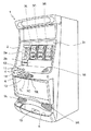
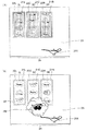
図1は、本発明に係る遊技機1の概観を示す斜視図である。尚、この遊技機1では、遊技媒体としてメダルが用いられているが、遊技媒体はこれに限られるものではなく、コイン、遊技球又はトークンなどの他、遊技者に付与された、又は付与される遊技価値の情報を記憶したカード等も適用可能である。
FIG. 1 is a perspective view showing an overview of a
前面ドア2の正面には、略垂直面としてのパネル表示部2a、液晶表示部2b及び固定表示部2cが形成されている(後述)。また、前面ドア2の背後には、複数種類の図柄が各々の外周面に描かれた3個のリール3L,3C,3Rが、回転自在に横一列に設けられている。各リール3L,3C,3Rは、定速回転(例えば、80回転/分)が可能なように構成されている。
On the front surface of the
また、パネル表示部2a、液晶表示部2b及び固定表示部2cの下方には略水平面の台座部4が形成されている。台座部4の左側には、押下操作により、クレジットされているメダルを賭けるための1−BETスイッチ11、2−BETスイッチ12、及び最大BETスイッチ13が設けられている。1−BETスイッチ11は、1回の押し操作により、クレジットされているメダルのうちの1枚がゲームに賭けられ、2−BETスイッチ12は、1回の押し操作により、クレジットされているメダルのうちの2枚がゲームに賭けられ、最大BETスイッチ13は、1回のゲームに賭けることが可能な最大枚数のメダルが賭けられる。これらのBETスイッチ11〜13を操作することで、所定の入賞ラインが有効化される(後述)。また、台座部4の右側には、メダルを投入するためのメダル投入口10が設けられている。
A substantially
台座部4の前面部の左寄りには、遊技者がゲームを通じて獲得したり、メダル投入口10に投入されたりしたメダルのクレジット/払い出しを切り換えるC/Pスイッチ14が設けられている。このC/Pスイッチ14の切り換えにより、正面下部のメダル払出口15からメダルが払い出され、払い出されたメダルはメダル受け部5に溜められる。メダル払出口15の上方の左右には、スピーカ9L,9Rが設けられている。
A C /
C/Pスイッチ14の右側には、遊技者が各リール3L,3C,3Rを回転させるためのスタートレバー6が、所定の角度範囲で回動自在に取り付けられている。台座部4の前面部中央で、スタートレバー6の右側には、3個のリール3L,3C,3Rの回転をそれぞれ停止させるための3個の停止ボタン7L,7C,7Rが設けられている。
On the right side of the C /
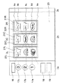
次に、図2を参照して、パネル表示部2a、液晶表示部2b及び固定表示部2cについて説明する。
Next, the
パネル表示部2aは、ボーナス遊技情報表示部16、BETランプ17a〜17c、払出表示部18、及びクレジット表示部19により構成される。ボーナス遊技情報表示部16は、7セグメントLEDから成り、ボーナス中の遊技情報を表示する。1−BETランプ17a、2−BETランプ17b及び最大BETランプ17cは、ゲームを行うために賭けられたメダルの数に応じて点灯する。1−BETランプ17aは、ゲームに賭けられたメダル数が1枚のときに点灯する。2−BETランプ17bは、ゲームに賭けられたメダル数が2枚のときに点灯する。最大BETランプ17cは、ゲームに賭けられたメダル数が3枚のときに点灯する。払出表示部18及びクレジット表示部19は、夫々7セグメントLEDから成り、入賞が成立した時のメダルの払出枚数及びクレジットされているメダルの枚数を表示する。
The
液晶表示部2bは、図柄表示領域21L,21C,21R、窓枠表示領域22L,22C,22R及び演出表示領域23により構成される。この液晶表示部2bの表示内容は、リール3L,3C,3Rの回転及び停止態様、及び後述の液晶表示装置131(後述の図3参照)の動作により変化するようになっている。
The liquid
図柄表示領域21L,21C,21Rは、各リール3L,3C,3Rに対応して設けられ、リール3L,3C,3R上に配置された図柄の表示や、種々の演出表示を行う。また、図柄表示領域21L,21C,21Rには、入賞ラインとして、水平方向にトップライン8b、センターライン8c及びボトムライン8d、並びに、斜め方向にクロスアップライン8a及びクロスダウンライン8eが設けられている。これらの入賞ラインは、遊技者が、前述のBETスイッチ11〜13を押下操作すること、又はメダル投入口10にメダルを投入することにより、それぞれ1本、3本、5本が有効化される(以下、有効化された入賞ラインを「有効ライン」と記載する)。図柄表示領域21L,21C,21Rは、少なくとも、対応するリール3L,3C,3Rが回転中のとき、及び、対応する停止ボタン7L,7C,7Rが押下操作可能なとき、遊技者がリール3L,3C,3R上の図柄を視認できるように、透過状態となる。
The
窓枠表示領域22L,22C,22Rは、各図柄表示領域21L,21C,21Rを囲むように設けられ、リール3L,3C,3Rの前面に配置された図柄表示領域21L,21C,21Rの窓枠を表したものである。
The window
演出表示領域23は、液晶表示部2bの領域のうち、図柄表示領域21L,21C,21R及び窓枠表示領域22L,22C,22R以外の領域である。この演出表示領域23は、特別入賞の成立が実現可能であることを確定的に報知する画像(例えば、告知ランプ)の表示、ゲームの興趣を増大するための演出、遊技者がゲームを有利に進めるために必要な情報等の表示を行う。実施例では、後述の図19、図20に示すような内部当選役の報知に関する画像の表示を行う。
The
固定表示部2cは、予め定めた図、絵などが描かれる領域である。この固定表示部2cに描かれた図、絵などと、演出表示領域23に表示された画像を連接させることにより一つの静止画像又は動画像を表示できるようにしても良い。
The fixed
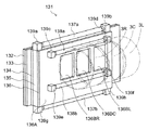
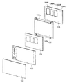
次に、図3、図4を参照して、透過型の液晶表示装置131について説明する。図3は、液晶表示装置131の概略構成を示す斜視図である。図4は、液晶表示装置131の一部の構成の展開図である。
Next, the transmissive liquid
液晶表示装置131は、保護ガラス132、表示板133、液晶パネル134、導光板135、反射フィルム136、白色光源(一般に可視域で発光する光源)である蛍光ランプ137a,137b,138a,138b、ランプホルダ139a〜139h、液晶パネル駆動用のICを搭載したテーブルキャリアパッケージからなり液晶パネル134の端子部に接続したフレキシブル基板(図示せず)等により構成される。この液晶表示装置131は、リール3L,3C,3Rの表示領域より正面から見て手前側(表示面よりも手前側)に設けられている。また、このリール3L,3C,3Rと液晶表示装置131とは、所定の間隔を開けて設けられている。
The liquid
保護ガラス132及び表示板133は、透光性部材で構成されている。保護ガラス132は、液晶パネル134を保護すること等を目的として設けられている。表示板133において、前述のパネル表示部2a及び固定表示部2c(図2参照)に対応する領域には、図、絵などが描かれる。ここで、図3、図4では、パネル表示部2aに対応する表示板133の領域の裏側に配置される前述の各種表示部(ボーナス遊技情報表示部16、払出表示部18、クレジット表示部19、図2参照)及びBETランプ17a〜17cを動作させる電気回路の図示を省略している。
The
液晶パネル134は、薄膜トランジスタ層が形成されたガラス板などの透明な基板と、これに対向する透明な基板との間隙部に液晶が封入されて形成されている。この液晶パネル134の表示モードは、ノーマリーホワイトに設定されている。ノーマリーホワイトとは、液晶を駆動していない状態で白表示(表示面側に光が行く、すなわち透過した光が外部から視認される)となる構成である。ノーマリーホワイトに構成された液晶パネル134を採用することにより、液晶を駆動できない事態が生じた場合であっても、図柄表示領域21L,21C,21Rを透してリール3L,3C,3R上に配列された図柄を視認することができ、ゲームを継続することができる。つまり、液晶を駆動できない事態が発生した場合にも、リール3L,3C,3Rの回転及びその停止を中心としたゲームを行うことができる。
The
導光板135は、蛍光ランプ137a,137bからの光を液晶パネル134へ導入する(液晶パネル134を照明する)ために液晶パネル134の裏側に設けられ、例えば2cm程度の厚さを有するアクリル系樹脂などの透光性部材(導光機能を有する)で構成されている。
The
反射フィルム136は、例えば白色のポリエステルフィルムやアルミ薄膜に銀蒸着膜を形成したものが用いられ、導光板135に導入された光を正面側に向けて反射させる。これにより液晶パネル134を照明する。この反射フィルム136には、矩形状の孔部136BL,136BC,136BRが形成されている。孔部136BL,136BC,136BRは、リール3L,3C,3Rの各々の前方に位置するように形成されている(リールシートに対応する領域)。尚、孔部136BL,136BC,136BRの大きさ及び位置は、前述の図柄表示領域21L,21C,21R(図2参照)と一致するように形成されている。また、反射フィルム136では、孔部136BL,136BC,136BR以外の領域を反射領域136Aとし、反射領域136Aにより導光板135に導入された光を正面側に向けて反射させる。
The
蛍光ランプ137a,137bは、導光板135の上端部及び下端部に沿って配置され、両端はランプホルダ139a、139b、139c、139dにより支持されている。この蛍光ランプ137a,137bは、導光板135に導入する光を発する。
The
蛍光ランプ138a,138bは、反射フィルム136の裏側の上方位置及び下方位置に孔部136BL,136BC,136BRを跨いで配置されている。この蛍光ランプ138a,138bから発せられた光は、リール3L,3C,3Rの表面で反射され、孔部136BL,136BC,136BRへ入射する。そして、入射した光は、孔部136BL,136BC,136BRを通過して液晶パネル134を照明する。
The
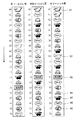
次に、図5を参照して、リール3L,3C,3R(より詳しくは、リール3L,3C,3Rの外周面に沿って装着されるリールシート)に描かれた図柄の配列(以下、「図柄配列」)について説明する。
Next, referring to FIG. 5, an arrangement of symbols (hereinafter referred to as “reel sheets mounted along the outer peripheral surfaces of the
各図柄には“00”〜“20”のコードナンバーが付され、データテーブルとして後述するROM32(図13)に格納されている。図5に示すように、各リール3L,3C,3R上には、“赤7(図柄91)”、“青7(図柄92)”、“BAR(図柄93)”、“ベル(図柄94)”、“スイカ(図柄95)”、“Replay(図柄96)”及び“チェリー(図柄97)”の図柄から構成された図柄配列が描かれている。リール3L,3C,3Rは、図柄配列が図5の矢印方向に移動するように回転駆動される。
Each symbol is assigned a code number “00” to “20”, and is stored in a ROM 32 (FIG. 13) described later as a data table. As shown in FIG. 5, on each
次に、実施例における遊技状態について説明する。実施例における遊技状態には、一般遊技状態、内部当選状態、BB中一般遊技状態及びRB遊技状態がある。 Next, the gaming state in the embodiment will be described. The gaming state in the embodiment includes a general gaming state, an internal winning state, a general gaming state during BB, and an RB gaming state.
「内部当選状態」は、一般遊技状態において、BB又はRB(以下総称してボーナスという場合がある)に内部当選し、内部当選したゲームで入賞を成立させることができなかった場合に移行する遊技状態(ボーナスが持ち越された遊技状態)である。すなわち、実施例では、ボーナスに内部当選した後、ボーナスが入賞するまでの間、ボーナスを内部当選役として保持することにより、ボーナスを持ち越すことができる。持ち越されたボーナスを、以下「持越役」という。持越役がBBである遊技状態を、以下「BB内部当選状態」という。持越役がRBである遊技状態を、以下「RB内部当選状態」という。内部当選状態では、ボーナスの入賞が許容された状態にあり、目押しを行うことによりボーナスの入賞を成立させることができる。 “Internally winning state” is a game that shifts in the general gaming state when BB or RB (hereinafter sometimes collectively referred to as a bonus) is internally won and a winning is not achieved in the internally won game. State (game state with bonus carried over). That is, in the embodiment, the bonus can be carried over by holding the bonus as an internal winning combination until the bonus is won after the bonus is won internally. The bonus carried over is referred to as “carryover” below. The gaming state in which the carryover combination is BB is hereinafter referred to as “BB internal winning state”. The gaming state in which the carryover combination is RB is hereinafter referred to as “RB internal winning state”. In the internal winning state, the bonus winning is permitted, and the bonus winning can be established by pushing.
「BB中一般遊技状態」は、一般遊技状態又は内部当選状態において、BBが入賞することにより発生する遊技状態である。通常、BB中一般遊技状態では、小役及びRBに内部当選する確率が、一般遊技状態と比べて高くなるように構成されている。BB中一般遊技状態は、その遊技状態で実行されたゲーム回数が30回に達するか、RB遊技状態へ移行した回数が3回に達した時点で終了するものとする(いわゆるAタイプ)。ここで、BBが入賞することにより発生し、BB中一般遊技状態及びRB遊技状態により構成される遊技状態を、以下「BB遊技状態」という場合がある。 The “BB general gaming state” is a gaming state that is generated when the BB wins in the general gaming state or the internal winning state. Normally, in the general gaming state during the BB, the probability that the small winning combination and the RB are internally won is higher than that in the general gaming state. The general game state during BB ends when the number of games executed in the game state reaches 30 times or when the number of times of transition to the RB game state reaches 3 times (so-called A type). Here, a game state that is generated when a BB wins and is configured by a general game state during BB and an RB game state may be hereinafter referred to as a “BB game state”.
「RB遊技状態」は、一般遊技状態、RB内部当選状態においてRBが入賞すること、又はBB中一般遊技状態においてRB(いわゆる「JACイン」)が入賞することにより移行する。通常、RB遊技状態では、後述の「JACの小役」に高確率で内部当選するように構成されている。RB遊技状態は、その遊技状態で実行されたゲーム回数が12回に達するか、12回のゲーム回数のうち「JACの小役」の入賞回数が8回に達した時点で終了するものとする。 The “RB gaming state” is shifted when the RB wins in the general gaming state or the RB internal winning state, or when the RB (so-called “JAC in”) wins in the BB general gaming state. Normally, in the RB gaming state, a “JAC small part” described later is configured to win internally with a high probability. The RB gaming state ends when the number of games executed in the gaming state reaches 12 times, or the number of winning of “JAC Minor” reaches 8 times out of the 12 game times. .
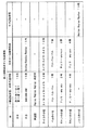
次に、図6を参照して、入賞が成立する図柄の組合せと、その配当について、遊技状態毎に説明する。 Next, with reference to FIG. 6, a combination of symbols for winning a prize and a payout thereof will be described for each gaming state.
一般遊技状態又はBB内部当選状態において、一つの有効ラインに沿って、“赤7(図5の図柄91)”又は“青7(図5の図柄92)”が3つ並ぶと、BBの入賞が成立する。BBの入賞が成立すると、15枚のメダルが払い出され、遊技状態がBB中一般遊技状態に移行する。
In the general gaming state or in the BB internal winning state, when three “red 7 (
一般遊技状態又はRB内部当選状態において、一つの有効ラインに沿って、“BAR(図5の図柄93)”が3つ並ぶか、又は、BB中一般遊技状態において、一つの有効ラインに沿って、“Replay(図5の図柄96)”が3つ並ぶと、RBの入賞が成立する。RBの入賞が成立すると、15枚のメダルが払い出され、遊技状態がRB遊技状態に移行する。BB中一般遊技状態においてRBが入賞することを、「JACイン」と称する。
In the general gaming state or the RB internal winning state, three “BARs (
一般遊技状態又は内部当選状態において、一つの有効ラインに沿って、“Replay”が3つ並ぶと、いわゆる再遊技の入賞が成立する。再遊技の入賞が成立すると、投入したメダルの枚数と同数のメダルが自動投入されるので、遊技者は、メダルを消費することなく、次のゲームを行うことができる。 In the general gaming state or the internal winning state, when three “Replays” are arranged along one active line, a so-called re-game winning is established. When a re-game winning is established, the same number of medals as the number of inserted medals are automatically inserted, so that the player can play the next game without consuming the medals.
一般遊技状態、内部当選状態、又は、BB中一般遊技状態において、一つの有効ラインに沿って、“スイカ”が3つ並ぶと、「スイカの小役」の入賞が成立する。「スイカの小役」の入賞が成立すると、12枚のメダルが払い出される。 In the general gaming state, the internal winning state, or the general gaming state during the BB, when three “watermelons” are arranged along one active line, a “watermelon small part” winning is established. When the winning “watermelon small role” is established, 12 medals are paid out.
一般遊技状態、内部当選状態、又は、BB中一般遊技状態において、一つの有効ラインに沿って、“ベル”が3つ並ぶと、「ベルの小役」の入賞が成立する。「ベルの小役」の入賞が成立すると、7枚のメダルが払い出される。 In the general gaming state, the internal winning state, or the general gaming state during the BB, when three “bells” are arranged along one active line, a winning of “bell small part” is established. When the winning of “Bell's small role” is established, seven medals are paid out.
一般遊技状態、内部当選状態、又は、BB中一般遊技状態において、一つの有効ラインに沿って、“チェリー(図5の図柄97)−any−any”が並ぶと、「チェリーの小役」の入賞が成立する。“any”とは、如何なる図柄でも良いことを示すものである。つまり、ゲームの結果、左リール3Lに配置された“チェリー(図5の図柄97)”が、左の図柄表示領域21Lの上段、中段及び下段の何れかに表示された場合に、入賞が成立する。「チェリーの小役」には、「中チェリーの小役」と「角チェリーの小役」の2種類がある。“チェリー(図5の図柄97)”が、左の図柄表示領域21Lの上段及び下段に表示されると、「角チェリーの小役」の入賞が成立し、4枚のメダルが払い出される。また、“チェリー(図5の図柄97)”が、左の図柄表示領域21Lの中段に表示されると、「中チェリーの小役」の入賞が成立し、2枚のメダルが払い出される。
In the general gaming state, the internal winning state, or the general gaming state during the BB, when “cherry (
RB遊技状態において、一つの有効ラインに沿って、“Replay”が3つ並ぶと、いわゆる「JACの小役」の入賞が成立する。「JACの小役」の入賞が成立すると、15枚のメダルが払い出される。RB遊技状態では、8回まで「JACの小役」の入賞を成立させることができる。 In the RB gaming state, when three “Replays” are arranged along one active line, a so-called “JAC small part” winning is established. When the winning of “JAC small role” is established, 15 medals are paid out. In the RB gaming state, a “JAC small part” winning can be established up to eight times.
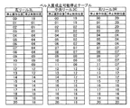
次に、図7を参照して、後述の主制御回路71のROM32(図13参照)に格納される確率抽選テーブルについて説明する。
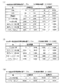
Next, a probability lottery table stored in the ROM 32 (see FIG. 13) of the
図7(1)は、一般遊技状態において、内部当選役を決定する際(後述の図16のステップS15)に用いられる確率抽選テーブルを示す。この確率抽選テーブルでは、“0”〜“16383”の範囲から抽出した乱数値が“0”〜“67”の範囲内の値である場合に、内部当選役がBBと決定される。BBが内部当選する確率は“68/16384”である。また、乱数値が“68”〜“112”の範囲内の値である場合に内部当選役がRBと決定される。RBが内部当選する確率は“45/16384”である。 FIG. 7 (1) shows a probability lottery table used for determining an internal winning combination (step S15 in FIG. 16 described later) in the general gaming state. In this probability lottery table, when the random value extracted from the range “0” to “16383” is a value within the range “0” to “67”, the internal winning combination is determined to be BB. The probability that BB will win internally is “68/16384”. Further, when the random value is a value within the range of “68” to “112”, the internal winning combination is determined to be RB. The probability that RB wins internally is “45/16384”.
また、再遊技が内部当選する確率は“2244/16384”、スイカの小役が内部当選する確率は“109/16384”、ベルの小役が内部当選する確率は“1673/16384”、中チェリーの小役が内部当選する確率は“64/16384”、及び角チェリーの小役が内部当選する確率は“49/16384”であり、いわゆるハズレ(なし)が内部当選する確率は“12132/16384”となる。実施例では、内部当選役には、入賞に係る役に限らず、ハズレ(なし)も含まれる。 In addition, the probability that the replay will win internally is “2244/16384”, the probability that the watermelon small role will win internally is “109/16384”, the probability that the Bell small role will win internally is “1673/16384”, medium cherry The probability of winning a small role is “64/16384”, and the probability of winning a small cherry role is “49/16384”, so the probability that a so-called “losing” (none) is won internally is “12132/16384” " In the embodiment, the internal winning combination includes not only the winning combination but also losing (none).
また、内部当選状態において、内部当選役を決定する際には、図7(1)に示す確率抽選テーブルを使用する。ただし、実施例では、内部当選状態において、BB又はRBが内部当選することはない。内部当選状態では、ハズレ(なし)に内部当選する確率は“12245/16384”となり、それ以外の内部当選役に内部当選する確率は図7(1)と同様である。 Further, when determining the internal winning combination in the internal winning state, the probability lottery table shown in FIG. 7A is used. However, in the embodiment, in the internal winning state, BB or RB does not win internally. In the internal winning state, the probability of winning an internal win is “12245/16384”, and the probability of winning an internal winning combination other than that is the same as in FIG. 7A.
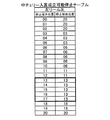
図7(2)は、BB中一般遊技状態において、内部当選役を決定する際(後述の図16のステップS15)に用いられる確率抽選テーブルを示す。この確率抽選テーブルでは、ベルの小役が内部当選する確率は“10750/16384”、中チェリーの小役が内部当選する確率は“164/16384”、及び角チェリーの小役が内部当選する確率は“149/16384”であり、一般遊技状態と比較して高確率となっている。ハズレ(なし)が内部当選する確率は“1225/16384”となる。 FIG. 7 (2) shows a probability lottery table used for determining the internal winning combination (step S15 in FIG. 16 described later) in the BB general game state. In this probability lottery table, the probability that Bell's small role will win internally is “10750/16384”, the probability that Medium Cherry ’s small role will win internally is “164/16384”, and the probability that Horny Cherry ’s small role will win internally. Is “149/16384”, which is a higher probability than the general gaming state. The probability that a loser (nothing) will win internally is “1225/16384”.
また、BB中一般遊技状態では、“0”〜“16383”の範囲から抽出した乱数値が“11063”〜“15158”の範囲内の値である場合に、内部当選役がRB(JACIN)と決定される。RB(JACIN)が内部当選する確率は“4096/16384”であり、一般遊技状態と比較して高確率となっている。また、BB中一般遊技状態では、BB、RB、再遊技、スイカの小役が内部当選することはない。 Also, in the general gaming state during BB, when the random number extracted from the range of “0” to “16383” is a value within the range of “11063” to “15158”, the internal winning combination is RB (JACIN). It is determined. The probability of RB (JACIN) winning internally is “4096/16384”, which is higher than the general gaming state. Also, in the general game state during BB, BB, RB, replay, and watermelon small combination will not win internally.
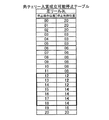
図7(3)は、RB遊技状態において、内部当選役を決定する際(後述の図16のステップS15)に用いられる確率抽選テーブルを示す。この確率抽選テーブルでは、“0”〜“16383”の範囲から抽出した乱数値が“0”〜“16219”の範囲内の値である場合に、内部当選役がJACの小役と決定される。JACの小役が内部当選する確率は“16220/16384”であり、高確率で決定される。ハズレ(なし)が内部当選する確率は“164/16384”となる。また、RB遊技状態では、BB、RB、再遊技、スイカの小役、ベルの小役、中チェリーの小役、角チェリーの小役が内部当選することはない。 FIG. 7 (3) shows a probability lottery table used for determining an internal winning combination (step S15 in FIG. 16 described later) in the RB gaming state. In this probability lottery table, when the random value extracted from the range of “0” to “16383” is a value within the range of “0” to “16219”, the internal winning combination is determined as the JAC small combination. . The probability that a JAC small role is won internally is “16220/16384”, which is determined with a high probability. The probability that a loser (no) will win internally is “164/16384”. Also, in the RB gaming state, BB, RB, replay, watermelon small part, bell small part, medium cherry small part, and corner cherry small part are not won internally.
尚、遊技機1での内部当選役を決定するため使用する確率抽選テーブルには、図7に示すものに限らず複数種類を設けることができ、例えば、各遊技状態(BB中一般遊技状態、RB遊技状態など)に対応して複数設けることとしても良い。
Note that the probability lottery table used to determine the internal winning combination in the
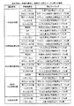
次に、図8を参照して、遊技状態と、内部当選役と、選択される停止テーブル群との関係について説明する。停止テーブル群は、後で図9〜図12を参照して説明する停止テーブルの集合を示し、リール3L,3C,3Rの停止制御の際に選択されるものである。
Next, with reference to FIG. 8, the relationship between the gaming state, the internal winning combination, and the selected stop table group will be described. The stop table group represents a set of stop tables which will be described later with reference to FIGS. 9 to 12, and is selected during stop control of the
ここで、選択される停止テーブル群の内容は、基本的に、遊技状態及び内部当選役毎に変化し得るものである。実施例では、図8の停止テーブル群の欄に示すテーブル群の名称を、入賞の可能性の有無や入賞の可能性がある内部当選役の種類に基づいて定めている。このため、実施例では、同一の名称の停止テーブル群が選択されたとしても、常にリール3L,3C,3Rの停止態様までもが一致するわけではない。
Here, the contents of the selected stop table group can basically change for each gaming state and internal winning combination. In the embodiment, the names of the table groups shown in the stop table group column of FIG. 8 are determined based on the possibility of winning and the type of internal winning combination that has the possibility of winning. For this reason, in the embodiment, even when stop table groups having the same name are selected, the stop modes of the
入賞不成立停止テーブル群が選択された場合には、内部当選役、遊技状態に拘らず、いずれの内部当選役の入賞も成立することはない。入賞成立可能停止テーブル群が選択された場合には、対応する内部当選役の入賞を成立しうるが、その他の内部当選役の入賞を成立することは基本的にできない。例えば、チェリー入賞成立可能停止テーブル群が選択された場合には、再遊技の入賞を成立しうるが、他の内部当選役の入賞を成立することはできない。 When the winning / non-winning stop table group is selected, no winning of any internal winning combination is achieved regardless of the internal winning combination and the gaming state. When the winning winning stop table group is selected, a winning of the corresponding internal winning combination can be established, but winning of other internal winning combinations is basically impossible. For example, when a stop table group that can be established for a cherry winning is selected, a re-game winning can be achieved, but a winning for another internal winning combination cannot be achieved.
図8に示すように、「一般遊技状態」において、ハズレ(なし)に内部当選した場合には、入賞不成立停止テーブル群が選択される。このため、いずれの内部当選役の入賞も成立することはない。また、ハズレ(なし)以外の内部当選役に内部当選した場合には、入賞成立可能停止テーブル群が選択される。このため、いずれの内部当選役の入賞も成立させることができる。 As shown in FIG. 8, in the “general gaming state”, when an internal win is made for a loss (none), a winning / losing stop table group is selected. Therefore, no winning of any internal winning combination is established. In addition, when an internal winning combination other than a loss (none) is won internally, a stop table group that can win a winning combination is selected. For this reason, winning of any internal winning combination can be established.
また、「内部当選状態」(BB内部当選状態、RB内部当選状態)において、ハズレ(なし)に内部当選した場合には、BB又はRB入賞成立可能停止テーブル群が選択される。このため、BB又はRBの入賞を成立させることができる。内部当選状態において、ハズレ(なし)に内部当選する確率は、“12245/16384”であり、高確率でBB又はRBの入賞を成立しうる。また、ハズレ(なし)以外の内部当選役に内部当選した場合も、入賞成立可能停止テーブル群が選択される。このため、いずれの内部当選役の入賞も成立させることができる。 In addition, in the “internal winning state” (BB internal winning state, RB internal winning state), if the internal winning is lost (none), the BB or RB winning establishment stop table group is selected. For this reason, BB or RB winning can be established. In the internal winning state, the probability of winning an internal win is “12245/16384”, and a BB or RB winning can be established with a high probability. In addition, even when the internal winning combination other than the loss (none) is won internally, the stop table group that can win a winning combination is selected. For this reason, winning of any internal winning combination can be established.
BB中一般遊技状態では、ハズレ(なし)に内部当選した場合には、入賞不成立停止テーブル群が選択される。一方、RB(JACIN)に内部当選した場合には、RB入賞成立可能停止テーブル群が選択される。このため、RB(JACIN)の入賞成立を実現することができる。また、ハズレ(なし)、RB(JACIN)以外の内部当選役に内部当選した場合も、入賞成立可能停止テーブル群が選択される。このため、いずれの内部当選役の入賞も成立させることができる。 In the general game state during BB, when the internal winning is made by losing (none), the winning / losing stop table group is selected. On the other hand, when RB (JACIN) is internally won, the RB winning establishment possible stop table group is selected. For this reason, it is possible to realize winning of RB (JACIN). In addition, even when an internal winning combination other than losing (none) and RB (JACIN) is won internally, the winning table in which a winning can be established is selected. For this reason, winning of any internal winning combination can be established.
また、RB遊技状態では、ハズレ(なし)に内部当選した場合には、入賞不成立停止テーブル群が選択される。一方、JACの小役に内部当選した場合には、JAC入賞成立可能停止テーブル群が選択される。このため、JACの小役の入賞を成立することができる。 Further, in the RB gaming state, when an internal win is made for a loss (none), a winning / losing stop table group is selected. On the other hand, when a JAC small combination is won internally, a JAC winning establishment possible stop table group is selected. For this reason, the winning of the JAC small role can be established.
次に、図9〜図12を参照して、後述の主制御回路71のROM32(図13参照)に格納される停止テーブルについて説明する。
Next, a stop table stored in a ROM 32 (see FIG. 13) of the
停止テーブルには、各リール3L,3C,3Rの停止操作位置と停止制御位置とが示されている。停止操作位置は、各リール3L,3C,3Rに対応して設けられた停止ボタン7L,7C,7Rが操作された場合に、センターライン8cに位置していた図柄(具体的には、図柄の中心がセンターライン8cの上方に位置し、その中心がセンターライン8cの位置に最も近い図柄)のコードナンバーを表わす。停止制御位置とは、停止操作が行われたリールが停止したとき、センターライン8cの位置に停止表示される図柄のコードナンバーを表わす。ここで、実施例では、いわゆる「滑りコマ数」を最大“4コマ”としている。図5を参照して、例えば、右リール3Rの回転中において、コードナンバー“13”の“BAR(図柄93)”がセンターライン8cの位置に到達したとき、停止ボタン7Rが操作された場合、コードナンバー“09”の“青7(図柄94)”をセンターライン8cの位置に停止表示するように右リール3Rを停止制御することができる。
The stop table shows stop operation positions and stop control positions of the
図9は、図8に示すベル入賞成立可能停止テーブル群に含まれるベル入賞可能停止テーブルを示す。このテーブルは、内部当選役がベルの小役の場合に、その入賞が成立するように各リール3L,3C,3Rを停止制御する際に使用される。
FIG. 9 shows a bell winning stop table included in the bell winning possible stop table group shown in FIG. This table is used when the
図9において、左リール3Lの停止制御位置は、コードナンバー“01”,“04”,“09”,“12”,“14”又は“18”のいずれかである。図5に示す図柄配列において、これらに対応する図柄は、“ベル(図柄94)”である。
In FIG. 9, the stop control position of the
また、中央リール3Cの停止制御位置は、コードナンバー“02”,“07”,“09”,“12”,“16”又は“19”のいずれかである。図5に示す図柄配列において、これらに対応する図柄は、“ベル(図柄94)”である。
The stop control position of the
更に、右リール3Rの停止制御位置は、コードナンバー“04”,“07”,“12”,“16”又は“20”のいずれかである。図5に示す図柄配列において、これらに対応する図柄は、“ベル(図柄94)”である。
Further, the stop control position of the
以上のように、図9に示すベル入賞成立可能停止テーブルが各リール3L,3C,3Rの停止制御に使用された場合には、センターライン8cに沿って、“ベル(図柄94)”が3つ並んで停止表示され、ベルの小役の入賞を必ず成立させることができる。
As described above, when the bell winning possible stop table shown in FIG. 9 is used for the stop control of the
実施例では、ベルの小役が内部当選した場合は、必ず入賞を成立することができるようになっている。これは、図5に示す図柄配列における“ベル(図柄94)”の配置に関係している。実施例では、いわゆる「滑りコマ数」を最大“4コマ”としており、停止操作を行った位置から“4コマ”の範囲に入賞を成立させる図柄があれば、有効ライン上に引き込むことが可能となっている。図5を参照すると、各リール3L,3C,3Rにおいて、“ベル(図柄94)”は、4コマの範囲に必ず配置されるような図柄配列となっている。このため、各リール3L,3C,3R上のどの位置で停止操作を行っても、“ベル(図柄94)”を有効ライン上に並べることが可能である。すなわち、基本的に、ベルの小役は、いわゆる「取りこぼし」(内部当選した内部当選役の入賞を成立させることができないこと)は起こらないようになっている。
In the embodiment, if a bell small part is elected internally, a winning can always be established. This is related to the arrangement of “bell (symbol 94)” in the symbol array shown in FIG. In the embodiment, the so-called “sliding frame number” is set to “4 frames” at the maximum, and if there is a symbol that establishes a winning in the range of “4 frames” from the position where the stop operation is performed, it can be drawn on the effective line. It has become. Referring to FIG. 5, in each of the
尚、実施例では、再遊技も取りこぼしが起こらない内部当選役となっている。すなわち、図5を参照すると、各リール3L,3C,3Rにおいて、“Replay(図柄96)”は、4コマの範囲に必ず配置されるような図柄配列となっている。
In the embodiment, the re-play is also an internal winning combination that does not cause a loss. That is, referring to FIG. 5, in each of the
図10は、中チェリー入賞可能停止テーブル群に含まれる中チェリー入賞可能停止テーブルを示す。このテーブルは、内部当選役が中チェリーの小役の場合に、その入賞が成立するように左リール3Lを停止制御する際に使用される。中チェリーの小役は、図柄表示領域21L内の中段に、“チェリー(図柄97)”が停止表示された場合に入賞が成立するため、図10に示す停止テーブルでは、中央リール3C又は右リール3Rについての停止操作位置及び停止制御位置に関する情報は省略することとしている。
FIG. 10 shows a middle cherry winning stop table included in the middle cherry winning stop table group. This table is used when the
図10において、左リール3Lの停止制御位置は、コードナンバー“03”,“06”,“08”,“11”,“13”、“16”又は“20”のいずれかである。図5に示す図柄配列において、太字で示されたコードナンバー“13”に対応する図柄は、“チェリー(図柄97)”である。また、“13”以外のコードナンバーに対応する図柄は、“Replay(図柄96)”である。
In FIG. 10, the stop control position of the
つまり、図10に示す停止テーブルでは、左リール3Lにおいて、太線で囲まれた停止操作位置で停止操作が行われた場合にのみ、中チェリーの小役の入賞を成立させることができ、太線で囲まれた以外の停止操作位置で停止操作が行われた場合には、中チェリーの小役の入賞を成立させることができない。
That is, in the stop table shown in FIG. 10, the winning of the medium cherry small part can be established only when the stop operation is performed at the stop operation position surrounded by the thick line on the
図11は、角チェリー入賞可能停止テーブル群に含まれる角チェリー入賞可能停止テーブルを示す。このテーブルは、内部当選役が角チェリーの小役の場合に、その入賞が成立するように左リール3Lを停止制御する際に使用される。角チェリーの小役は、図柄表示領域21L内の上段又は下段に、“チェリー(図柄97)”が停止表示された場合に入賞が成立するため、図11に示す停止テーブルでは、中央リール3C又は右リール3Rについての停止操作位置及び停止制御位置に関する情報は省略することとしている。
FIG. 11 shows a corner cherry winning stop table included in the corner cherry winning stop table group. This table is used when the
図11において、左リール3Lの停止制御位置は、コードナンバー“03”,“06”,“08”,“12”,“14”、“16”又は“20”のいずれかである。図5に示す図柄配列において、太字で示されたコードナンバー“12”に対応する図柄の1つ下の図柄は、“チェリー(図柄97)”である。また、太字で示されたコードナンバー“14”に対応する図柄の1つ上の図柄は、“チェリー(図柄97)”である。
In FIG. 11, the stop control position of the
つまり、図11に示す停止テーブルでは、左リール3Lにおいて、太線で囲まれた停止操作位置で停止操作が行われた場合にのみ、角チェリーの小役の入賞を成立させることができ、太線で囲まれた以外の停止操作位置で停止操作が行われた場合には、角チェリーの小役の入賞を成立させることができない。
That is, in the stop table shown in FIG. 11, the winning of the small part of the corner cherry can be established only when the stop operation is performed at the stop operation position surrounded by the thick line on the
図12は、スイカ入賞可能停止テーブル群に含まれるスイカ入賞可能停止テーブルを示す。このテーブルは、内部当選役がスイカの小役の場合に、その入賞が成立するように各リール3L,3C,3Rを停止制御する際に使用される。
FIG. 12 shows a watermelon winning stop table included in the watermelon winning stop table group. This table is used when the
図12において、左リール3Lの停止制御位置は、コードナンバー“02”,“05”,“10”,“11”,“16”,“17”又は“19”のいずれかである。図5に示す図柄配列において、太線で示したコードナンバーに対応する図柄は、“スイカ(図柄95)”である。また、太線以外のコードナンバー“11”及び“16”に対応する図柄は“Replay(図柄96)”である。
In FIG. 12, the stop control position of the
また、中央リール3Cの停止制御位置は、コードナンバー“01”,“04”,“06”,“10”,“15”又は“17”のいずれかである。図5に示す図柄配列において、太線で示したコードナンバー“04”及び“17”に対応する図柄は、“スイカ(図柄95)”である。また、太線以外のコードナンバーに対応する図柄は“Replay(図柄96)”である。
The stop control position of the
更に、右リール3Rの停止制御位置は、コードナンバー“02”,“06”,“10”,“15”又は“19”のいずれかである。図5に示す図柄配列において、太線で示したコードナンバー“06”、“15”及び“19”に対応する図柄は、“スイカ(図柄95)”である。また、太線以外のコードナンバーに対応する図柄は“Replay(図柄96)”である。
Further, the stop control position of the
つまり、図12に示す停止テーブルでは、各リール3L,3C,3Rにおいて、太線で囲まれた停止操作位置で停止操作が行われた場合にのみ、スイカの小役の入賞を成立させることができ、太線で囲まれた以外の停止操作位置で停止操作が行われた場合には、スイカの小役の入賞を成立させることができない。
That is, in the stop table shown in FIG. 12, the winning of the watermelon small part can be established only when the stop operation is performed at the stop operation position surrounded by the thick line in each
実施例では、中チェリーの小役、角チェリーの小役、又はスイカの小役が内部当選し、入賞成立可能停止テーブルが選択された場合であっても、入賞を成立させることができない場合がある。これは、図5に示す図柄配列における“チェリー(図柄97)”又は“スイカ(図柄95)”の配置に関係している。図5を参照すると、左リール3Lにおいて、“チェリー(図柄97)”は、4コマの範囲に配置されるような図柄配列ではなく、コードナンバー“13”の位置にしか配置されていない。このため、停止操作位置によっては、“チェリー(図柄97)”を有効ラインに停止させることができない。すなわち、中チェリーの小役又は角チェリーの小役は、いわゆる「取りこぼし」が起こりうる役として構成されている。また、同様に、図5を参照すると、各リール3L,3C,3Rにおいて、“スイカ(図柄95)”は、4コマの範囲に配置されるような図柄配列とはなっていない。このため、停止操作位置によっては、“スイカ(図柄95)”を有効ラインに停止させることができない。すなわち、スイカの小役は、いわゆる「取りこぼし」が起こりうる役として構成されている。
In the embodiment, even when the medium cherry, small cherry or watermelon small combination is won internally, and the winning establishment possible stop table is selected, the winning may not be established. is there. This is related to the arrangement of “cherry (symbol 97)” or “watermelon (symbol 95)” in the symbol array shown in FIG. Referring to FIG. 5, in the
尚、実施例では、取りこぼしが起こりうる内部当選役として、中チェリーの小役、角チェリーの小役、又はスイカの小役を例にして説明したが、BB(“赤7(図柄91)”、“青7(図柄92)”)、RB(“BAR(図柄93)”)も取りこぼしが起こりうる内部当選役である。すなわち、“赤7(図柄91)”、“青7(図柄92)”又は“BAR(図柄93)”は、ともに、各リール3L,3C,3Rにおいて、4コマの範囲に配置されるような図柄配列とはなっていない。このため、停止操作位置によっては、“赤7(図柄91)”、“青7(図柄92)”又は“BAR(図柄93)”を有効ラインに停止させることができない場合がある。
In the embodiment, as an internal winning combination that may be missed, a small cherry role, a small cherry role, or a watermelon small role has been described as an example, but BB ("Red 7 (symbol 91)" , “Blue 7 (symbol 92)”) and RB (“BAR (symbol 93)”) are also internal winning combinations that may be missed. That is, “red 7 (symbol 91)”, “blue 7 (symbol 92)” or “BAR (symbol 93)” is arranged in a range of 4 frames in each
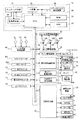
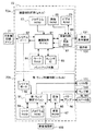
図13は、遊技機1における遊技処理動作を制御する主制御回路71と、主制御回路71に電気的に接続する周辺装置(アクチュエータ)と、主制御回路71から送信される制御指令に基づいて液晶表示装置131、スピーカ9L,9R、LED類101及びランプ類102を制御する副制御回路72とを含む回路構成を示す。
FIG. 13 is based on a
主制御回路71は、回路基板上に配置されたマイクロコンピュータ30を主たる構成要素とし、これに乱数サンプリングのための回路を加えて構成されている。マイクロコンピュータ30は、予め設定されたプログラムに従って制御動作を行うCPU31と、記憶手段であるROM32及びRAM33を含む。
The
CPU31には、基準クロックパルスを発生するクロックパルス発生回路34及び分周器35と、サンプリングされる乱数を発生する乱数発生器36及びサンプリング回路37とが接続されている。尚、乱数サンプリングのための手段として、マイクロコンピュータ30内で、即ちCPU31の動作プログラム上で、乱数サンプリングを実行するように構成してもよい。その場合、乱数発生器36及びサンプリング回路37は省略可能であり、或いは、乱数サンプリング動作のバックアップ用として残しておくことも可能である。
Connected to the
マイクロコンピュータ30のROM32には、スタートレバー6を操作(スタート操作)する毎に行われる乱数サンプリングの判定に用いられる確率抽選テーブル(図7)、停止ボタン7L,7C,7Rの操作に応じてリール3L,3C,3Rの停止態様を決定するための停止テーブル群、副制御回路72へ送信するための各種制御指令(コマンド)等が格納されている。副制御回路72が主制御回路71へコマンド、情報等を入力することはなく、主制御回路71から副制御回路72への一方向で通信が行われる。RAM33には、種々の情報が格納される。例えば、フラグ、遊技状態の情報等が格納される。
The
図13の回路において、マイクロコンピュータ30からの制御信号により動作が制御される主要なアクチュエータとしては、BETランプ(1−BETランプ17a、2−BETランプ17b、最大BETランプ17c)と、ボーナス遊技情報表示部16と、払出表示部18と、クレジット表示部19と、メダルを収納し、ホッパー駆動回路41の命令により所定枚数のメダルを払い出すホッパー(払出しのための駆動部を含む)40と、リール3L,3C,3Rを回転駆動するステッピングモータ49L,49C,49Rとがある。
In the circuit of FIG. 13, the main actuators whose operation is controlled by a control signal from the
更に、ステッピングモータ49L,49C,49Rを駆動制御するモータ駆動回路39、ホッパー40を駆動制御するホッパー駆動回路41、BETランプ17a,17b,17cを駆動制御するランプ駆動回路45、及び各種表示部を駆動制御する表示部駆動回路48がCPU31の出力部に接続されている。これらの駆動回路は、それぞれCPU31から出力される駆動指令などの制御信号を受けて、各アクチュエータの動作を制御する。
Further, a motor driving circuit 39 for driving and controlling the
また、マイクロコンピュータ30が制御指令を発生するために必要な入力信号を発生する主な入力信号発生手段としては、スタートスイッチ6S、1−BETスイッチ11、2−BETスイッチ12、最大BETスイッチ13、C/Pスイッチ14、メダルセンサ10S、リール停止信号回路46、リール位置検出回路50、払出完了信号回路51がある。
The main input signal generating means for generating an input signal necessary for the
スタートスイッチ6Sは、スタートレバー6の操作を検出する。メダルセンサ10Sは、メダル投入口10に投入されたメダルを検出する。リール停止信号回路46は、各停止ボタン7L,7C,7Rの操作に応じて停止信号を発生する。リール位置検出回路50は、リール回転センサからのパルス信号を受けて各リール3L,3C,3Rの位置を検出するための信号をCPU31へ供給する。払出完了信号回路51は、メダル検出部40Sの計数値(ホッパー40から払出されたメダルの枚数)が指定された枚数データに達した時、メダル払出完了を検知するための信号を発生する。
The
図13の回路において、乱数発生器36は、一定の数値範囲に属する乱数を発生し、サンプリング回路37は、スタートレバー6が操作された後の適宜のタイミングで1個の乱数をサンプリングする。こうしてサンプリングされた乱数及びROM32内に格納されている確率抽選テーブルに基づいて、当選役が決定される。
In the circuit of FIG. 13, the
リール3L,3C,3Rの回転が開始された後、ステッピングモータ49L,49C,49Rの各々に供給される駆動パルスの数が計数され、その計数値はRAM33の所定エリアに書き込まれる。リール3L,3C,3Rからは一回転毎にリセットパルスが得られ、これらのパルスはリール位置検出回路50を介してCPU31に入力される。こうして得られたリセットパルスにより、RAM33で計数されている駆動パルスの計数値が“0”にクリアされる。これにより、RAM33内には、各リール3L,3C,3Rについて一回転の範囲内における回転位置に対応した計数値が格納される。
After the rotation of the
上記のようなリール3L,3C,3Rの回転位置とリール外周面上に描かれた図柄とを対応づけるために、図柄テーブル(図示せず)が、ROM32内に格納されている。この図柄テーブルでは、前述したリセットパルスが発生する回転位置を基準として、各リール3L,3C,3Rの一定の回転ピッチ毎に順次付与されるコードナンバーと、それぞれのコードナンバー毎に対応して設けられた図柄を示す図柄コードとが対応づけられている。
A symbol table (not shown) is stored in the
更に、ROM32内には、入賞図柄組合せテーブル(図示せず)が格納されている。この入賞図柄組合せテーブルでは、入賞となる図柄の組合せと、入賞のメダル配当枚数と、その入賞を表わす入賞判定コードとが対応づけられている。上記の入賞図柄組合せテーブルは、左のリール3L,中央のリール3C,右のリール3Rの停止制御時、及び全リール3L,3C,3R停止後の入賞確認を行う場合に参照される。
Furthermore, a winning symbol combination table (not shown) is stored in the
上記乱数サンプリングに基づく抽選処理(確率抽選処理)により当選した場合には、CPU31は、遊技者が停止ボタン7L,7C,7Rを操作したタイミングでリール停止信号回路46から送られる操作信号、及び選択された「停止テーブル」に基づいて、リール3L,3C,3Rを停止制御する信号をモータ駆動回路39に送る。
When winning by the lottery process (probability lottery process) based on the random number sampling, the
当選した役の入賞を示す停止態様となれば、CPU31は、払出指令信号をホッパー駆動回路41に供給してホッパー40から所定個数のメダルの払出を行う。その際、メダル検出部40Sは、ホッパー40から払出されるメダルの枚数を計数し、その計数値が指定された数に達した時に、メダル払出完了信号がCPU31に入力される。これにより、CPU31は、ホッパー駆動回路41を介してホッパー40の駆動を停止し、「メダル払出処理」を終了する。
In the stop mode indicating winning of the winning combination, the
図14は、副制御回路72の構成を示すブロック図である。副制御回路72は、画像制御回路(gSub)72aと、音・ランプ制御回路(mSub)72bとから構成されている。この画像制御回路(gSub)72a又は音・ランプ制御回路(mSub)72bは、主制御回路71を構成する回路基板とは各々別の回路基板上に構成されている。
FIG. 14 is a block diagram showing a configuration of the
主制御回路71と画像制御回路(gSub)72aとの間の通信は、主制御回路71から画像制御回路(gSub)72aへの一方向で行われ、画像制御回路(gSub)72aから主制御回路71へコマンド、情報等が送信されることはない。また、画像制御回路(gSub)72aと音・ランプ制御回路(mSub)72bとの間の通信は、画像制御回路(gSub)72aから音・ランプ制御回路(mSub)72bへの一方向で行われ、音・ランプ制御回路(mSub)72bから画像制御回路(gSub)72aへコマンド、情報等が送信されることはない。
Communication between the
画像制御回路(gSub)72aは、画像制御マイコン81、シリアルポート82、プログラムROM83、ワークRAM84、カレンダIC85、画像制御IC86、制御RAM87、画像ROM(CROM(キャラクタROM))88及びビデオRAM89で構成される。
The image control circuit (gSub) 72a includes an
画像制御マイコン81は、CPU、割込コントローラ、入出力ポート(何れも図示せず)を備えている。画像制御マイコン81に備えられたCPUは、主制御回路71から送信されたコマンドに基づき、プログラムROM83内に格納された制御プログラムに従って各種の処理(後述の図18参照)を行う。尚、画像制御回路(gSub)72aは、クロックパルス発生回路、分周器、乱数発生器及びサンプリング回路を備えていないが、各種の処理を行うために乱数が必要となった場合には、画像制御マイコン81の動作プログラム上で乱数サンプリングを実行するように構成されている。
The
シリアルポート82は、主制御回路71から送信される各種のコマンド、情報等を受信する。
The
プログラムROM83は、画像制御マイコン81で実行する制御プログラムや決定用テーブル等を格納する。
The program ROM 83 stores a control program executed by the
ワークRAM84は、画像制御マイコン81が制御プログラムを実行する際に必要な各種の情報を記憶するための作業用の一時記憶手段として構成される。
The
カレンダIC85は、日付データを記憶する。画像制御マイコン81には、操作部104が接続されている。実施例では、この操作部104を遊技場の従業員等が操作することにより日付の設定等が行われるようになっている。画像制御マイコン81は、操作部104から送信される入力信号に基づいて設定された日付情報をカレンダIC85に記憶する。カレンダIC85に記憶された日付情報はバックアップされることとなる。
The
また、前述のワークRAM84とカレンダIC85は、バックアップ対象となっている。つまり、画像制御マイコン81に供給される電源が遮断された場合であっても、電源が供給され続け、記憶された情報等の消去が防止される。
The
画像制御IC86は、画像制御マイコン81により決定された演出内容に応じた画像を生成し、液晶表示装置131に出力する。
The
制御RAM87は、画像制御IC86の中に含まれている。画像制御マイコン81は、この制御RAM87に対して情報等の書き込みや読み出しを行う。また、制御RAM87には、画像制御IC86のレジスタと、スプライト属性テーブルと、カラーパレットテーブルと、が展開されている。画像制御マイコン81は、画像制御IC86のレジスタと、スプライト属性テーブルとを所定のタイミングごとに更新する。
The
画像制御IC86には、液晶表示装置131と、画像ROM88と、ビデオRAM89とが接続されている。
A liquid
画像ROM88は、画像を生成するための画像データ、ドットデータ等を格納する。
The
ビデオRAM89は、画像制御IC86で画像を生成する際の一時記憶手段として構成される。
The
また、画像制御IC86は、ビデオRAM89のデータを液晶表示装置131に転送終了する(1/60秒)毎に画像制御マイコン81に信号を送信する(次の処理の開始)。
In addition, the
また、画像制御回路(gSub)72aでは、画像制御マイコン81が、音・ランプの演出の制御も行うこととなっている。画像制御マイコン81は、決定された演出に基づいて、音・ランプの種類及び出力タイミングを決定する。そして、画像制御マイコン81は、所定のタイミングごとに、音・ランプ制御回路(mSub)72bにシリアルポート82を介してコマンドを送信する。音・ランプ制御回路(mSub)72bでは、主に、画像制御回路(gSub)72aから送信されたコマンドに応じて、音・ランプの出力のみを行うこととなる(後述する音量調節制御を除く)。
In the image control circuit (gSub) 72a, the
音・ランプ制御回路(mSub)72bは、音・ランプ制御マイコン91、シリアルポート92、プログラムROM93、ワークRAM94、音源IC95、パワーアンプ96、音源ROM97で構成される。
The sound / lamp control circuit (mSub) 72b includes a sound /
音・ランプ制御マイコン91は、CPU、割込コントローラ、入出力ポート(何れも図示せず)を備えている。音・ランプ制御マイコン91に備えられたCPUは、画像制御回路(gSub)72aから送信されたコマンドに基づき、プログラムROM93内に格納された制御プログラムに従って音・ランプの出力処理を行う。また、音・ランプ制御マイコン91には、LED類101及びランプ類102が接続されている。音・ランプ制御マイコン91は、画像制御回路(gSub)72aから所定のタイミングで送信されるコマンドに応じて、このLED類101及びランプ類102に出力信号を送信する。これにより、LED類101及びランプ類102が演出に応じた所定の態様で発光することとなる。
The sound /
シリアルポート92は、画像制御回路(gSub)72aから送信される各種のコマンド、情報等を受信する。
The
プログラムROM93は、音・ランプ制御マイコン91で実行する制御プログラム等を格納する。
The
ワークRAM94は、音・ランプ制御マイコン91が制御プログラムを実行する際に必要な各種の情報を記憶するための作業用の一時記憶手段として構成される。
The
音源IC95は、画像制御回路(gSub)72aから送信されたコマンドに基づいて音源を生成し、パワーアンプ96に出力する。
The
パワーアンプ96は増幅器であり、このパワーアンプ96にはスピーカ9L,9Rが接続されている。パワーアンプ96は、音源IC95から出力された音源を増幅し、増幅した音源をスピーカ9L,9Rから出力させる。
The
音源ROM97は、音源を生成するための音源データ(フレーズ等)等を格納する。
The
また、音・ランプ制御マイコン91には、音量調節部103が接続されている。音量調節部103は、遊技場の従業員等により操作可能となっており、スピーカ9L,9Rから出力される音量の調節が行われる。音・ランプ制御マイコン91は、音量調節部103から送信される入力信号に基づいて、スピーカ9L,9Rから出力される音を入力された音量に調節する制御を行う。
The sound /
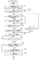
次に、図15〜図17に示すメインフローチャートを参照して、主制御回路71のCPU31の制御動作について説明する。
Next, the control operation of the
初めに、CPU31は、ゲーム開始時の初期化を行う(ステップS1)。具体的には、RAM33の記録内容の初期化、副制御回路72との間の通信データの初期化等を行う。続いてゲーム終了時のRAM33の所定の記録内容を消去する(ステップS2)。具体的には、前回のゲームに使用されたRAM33の書き込み可能エリアのデータの消去、RAM33の書き込みエリアへの次のゲームに必要なパラメータの書き込み、次のゲームのシーケンスプログラムの開始アドレスの指定等を行う。
First, the
次に、CPU31は、前回のゲーム終了後、すなわち全リール3L,3C,3R停止後から“30秒”経過したか否かを判別する(ステップS3)。この判別が“YES”であれば、副制御回路72に対し、「デモ画像」の表示を要求する「デモ表示コマンド」を送信し(ステップS4)、ステップS5に移る。また、判別が“NO”であれば、ステップS5に移る。
Next, the
ステップS5では、CPU31は、メダルの自動投入の要求があるか、すなわち前回のゲームで再遊技が入賞したか否かを判別する。この判別が“YES”の場合は、投入要求分のメダルを自動投入し(ステップS6)、ステップS8に移る。一方、ステップS5の判別が“NO”の場合は、メダルセンサ10S又はBETスイッチ11〜13からの入力があるか否かを判別する(ステップS7)。この判別が“YES”の場合は、ステップS8に移り、“NO”の場合は、ステップS3に移る。
In step S5, the
ステップS8では、CPU31は、副制御回路72に対してBETスイッチ11〜13の操作又はメダルを投入する操作が行われた情報を示す「BETコマンド」を送信する。続いて、スタートレバー6の操作に基づくスタートスイッチ6Sからの入力があるか否かを判別する(ステップS9)。この判別が“YES”の場合は、ステップS10に移り、“NO”の場合は、ステップS9を繰り返し行う。
In step S <b> 8, the
ステップS10では、CPU31は、前回のゲームが開始してから“4.1秒”経過しているか否かを判別する。この判別が“YES”の場合は、ステップS12に移り、“NO”の場合は、ステップS11に移る。ステップS11では、「ゲーム開始待ち時間消化処理」を行う。具体的には、前回のゲームが開始してから“4.1秒”経過するまでの間、遊技者のゲームを開始する操作に基づく入力を無効にする処理を行う。ステップS12では、リールの回転処理を行い、図16のステップS13に移る。
In step S10, the
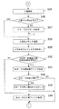
図16のステップS13では、CPU31は、抽選用の乱数を“0”〜“16383”の範囲から抽出する。ステップS13の処理で抽出した乱数は、後述の確率抽選処理において使用される。続いて1ゲーム監視用タイマをセットする(ステップS14)。ステップS14の処理の1ゲーム監視用タイマには、遊技者の停止ボタン7L,7C,7Rの停止操作に基づかずに自動的にリール3L,3C,3Rを停止させるための自動停止タイマが含まれる。
In step S13 in FIG. 16, the
次に、CPU31は、確率抽選処理を行う(ステップS15)。この確率抽選処理は、ROM32に格納されている確率抽選テーブル(図7参照)を使用する。そして、遊技状態(図7(1)〜(3))に応じて、上記ステップS13において抽出した乱数値がどの役の乱数範囲に属するか否かを判別し、内部当選役(成立フラグ)を決定するものである。
Next, the
次に、CPU31は、停止テーブル群選択処理を行う(ステップS16)。この停止テーブル群選択処理は、ROM32に格納されている停止テーブル群選択テーブル(図8参照)を使用する。そして、遊技状態、内部当選役などに基づいて停止テーブル群を決定する。
Next, the
次に、遊技状態、ステップS15で決定した内部当選役、ステップS16で決定した停止テーブル群などの情報を含むゲーム開始時のコマンド(スタートコマンド)を副制御回路72へ送信する(ステップS17)。副制御回路72では、所定条件の成立により、受信したスタートコマンドに含まれる内部当選役の情報に基づいて内部当選役の種類を報知するための演出画像を液晶表示装置131に対して表示させる。
Next, a command at the start of the game (start command) including information such as the gaming state, the internal winning combination determined in step S15, and the stop table group determined in step S16 is transmitted to the sub-control circuit 72 (step S17). The
次に、CPU31は、停止ボタンが“オン”されたかどうかを判別する(ステップS18)。具体的には、いずれかの停止ボタン7L,7C,7Rが操作されたかどうかを判別する。この判別が“YES”の場合は、ステップS20に移り、“NO”の場合は、ステップS19に移る。ステップS19では、自動停止タイマの値が“0”であるか否かを判別し、この判別が“YES”の場合は、ステップS20に移り、“NO”の場合は、ステップS18に移る。
Next, the
ステップS20では、CPU31は、滑りコマ数決定処理を行う。具体的には、ステップS16で決定された停止テーブル群の中から停止テーブルを選択し、選択した停止テーブルに含まれる停止操作位置及び停止制御位置の情報に基づいて滑りコマ数を決定する。例えば、停止操作位置がコードナンバー“17”であり、停止制御位置がコードナンバー“13”であれば、滑りコマ数として“4”コマを決定する。
In step S20, the
次に、滑りコマ数分、停止操作された停止ボタンに対応するリールを滑りコマ数分回転させた後、停止させる(ステップS21)。続いて、停止制御の対象であるリール(操作された停止ボタン7L,7C,7Rに対応するリール3L,3C,3R)の情報などを含む「リール停止コマンド」を副制御回路72へ送信し(ステップS22)、ステップS23に移る。リール停止コマンドには、停止制御の対象となったリールの停止制御位置の情報(図柄表示領域内に表示されたリールの停止図柄情報)が含まれる。
Next, the reel corresponding to the stop button that has been stopped is rotated by the number of sliding frames and then stopped (step S21). Subsequently, a “reel stop command” including information on the reels subject to stop control (
ステップS23では、全てのリール3L,3C,3Rが停止したかどうかを判別する(ステップS23)。この判別が“YES”の場合は、ステップS24に移り、“NO”の場合は、ステップS18に移る。ステップS24では、全てのリール3L,3C,3Rが停止したことを示す全リール停止コマンドを副制御回路72に送信する。
In step S23, it is determined whether or not all the
次に、図17に移り、CPU31は、入賞検索を行う(ステップS25)。入賞検索とは、図柄表示領域21L,21C,21R内に表示された図柄の停止態様に基づいて入賞役(入賞が成立した役)を識別するための入賞フラグをセットすることである。具体的には、センターライン8cに沿って並ぶ図柄のコードナンバー(停止制御位置のコードナンバー)及び入賞判定テーブルに基づいて入賞役を識別する。続いて、入賞フラグが正常であるか否かを判別する(ステップS26)。この判別が“NO”の場合はイリーガルエラーの表示を行う(ステップS27)。この場合、遊技は中止となる。一方、ステップS26の判別が“YES”の場合は、入賞の成立・不成立の情報、入賞役(入賞が成立した役)の情報を含む入賞役コマンドを副制御回路72へ送信する(ステップS28)。続いて、入賞役に対応するメダルのクレジット又は払出しを行う(ステップS29)。
Next, moving to FIG. 17, the
次に、CPU31は、現在の遊技状態がBB中一般遊技状態又はRB遊技状態であるか否かを判別する(ステップS30)。この判別が“NO”の場合(遊技状態がBB中一般遊技状態又はRB遊技状態でない場合)は、ステップS34に移り、“YES”の場合は、ステップS31に移る。ステップS31では、ボーナス(BB又はRB)の「遊技数チェック処理」を行う。この「遊技数チェック処理」では、BB中一般遊技状態のゲーム回数、RB遊技状態が発生した回数、RB遊技状態におけるゲーム回数、及びRB遊技状態における入賞回数をチェックするとともに、遊技状態の移行(セット)を行う。
Next, the
次に、ボーナス(BB又はRB)の終了時であるか否かを判別する(ステップS32)。具体的には、BBが入賞した後では、3回目のRB遊技状態においてJACの小役の入賞回数が8回又はゲーム回数が12回に達したか、又はBB中一般遊技状態においてゲーム回数が30回に達したか否かを判別する。また、一般遊技状態から移行したRB遊技状態では、JACの小役の入賞回数が8回又はゲーム回数が12回に達したか否かを判別する。ステップS32の判別が“YES”の場合は、BB遊技状態又はRB遊技状態の終了時のRAM33をクリアし(ステップS33)、図15のステップS2に移る。また、ステップS32の判別が“NO”の場合は、図15のステップS2に移る。
Next, it is determined whether or not the bonus (BB or RB) is over (step S32). Specifically, after the BB wins, the number of JAC small role winnings reaches 8 times or the number of games reaches 12 in the third RB gaming state, or the number of games in the general gaming state during BB It is determined whether or not 30 times has been reached. Further, in the RB gaming state shifted from the general gaming state, it is determined whether or not the number of winnings of the JAC small role has reached 8 or the number of games has reached 12. If the determination in step S32 is “YES”, the
また、前述のステップS30の判別が“NO”の場合は、BB・RB入賞チェック処理を行う(ステップS34)。この処理では、BB又はRBの入賞が成立したか否かを判別し、入賞が成立したボーナスに対応するボーナスフラグをオンとする。この処理の後、図15のステップS2に移る。 If the determination in step S30 is “NO”, a BB / RB winning check process is performed (step S34). In this process, it is determined whether or not BB or RB winning has been established, and a bonus flag corresponding to the bonus for which winning has been established is turned on. After this processing, the process proceeds to step S2 in FIG.
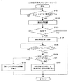
次に、図18に示すフローチャートを参照して、副制御回路72の制御動作について説明する。
Next, the control operation of the
初めに、副制御回路72の画像制御マイコン81は、スタートコマンドを受信したか否かを判別する(ステップS101)。スタートコマンドは図16のステップS17で主制御回路71から送信される。スタートコマンドには、抽選により決定された内部当選役の情報が含まれる。この判別が“YES”の場合は、ステップS102に移り、“NO”の場合は、ステップS101を繰り返す。
First, the
ステップS102では、演出実行抽選を行う。この処理では、例えば“0”〜“255”の範囲から抽出した乱数値と、演出実行抽選テーブル(例えば、乱数値が“0”〜“128”の範囲であれば演出実行に当選(確率“128/256”)し、“129”〜“255”の範囲であれば演出実行に不当選(確率“128/256”)する)とに基づいて、演出実行に当選か不当選かを決定する。続いて、演出実行抽選に当選したか否かを判別する(ステップS103)。この判別が“YES”の場合は、ステップS104に移り、“NO”の場合は、ステップS101に移る。 In step S102, an effect execution lottery is performed. In this process, for example, a random value extracted from the range of “0” to “255” and an effect execution lottery table (for example, if the random value is in the range of “0” to “128”, the effect is won (probability “ 128/256 ”), and if it is in the range of“ 129 ”to“ 255 ”, it is determined whether the performance is won or not (based on the probability of“ 128/256 ”). . Subsequently, it is determined whether or not an effect execution lottery has been won (step S103). If this determination is “YES”, the process proceeds to step S104, and if “NO”, the process proceeds to step S101.
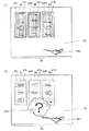
ステップS104では、演出開始画像を表示する。具体的には、図19(1)又は図20(1)に示すような演出開始時の画像を液晶表示装置131に表示させる。図19(1)又は図20(1)では、液晶表示装置131の液晶表示部2bの図柄表示領域21L,21C,21R内に、リール3L,3C,3R上の図柄が変動表示されている様子が示されている。また、演出表示領域23の右下方の位置に、演出開始画像201として、ランプを表した画像が表示されている様子が示されている。これにより、遊技者に対して内部当選役を報知する演出が行われることを認識させることができる。また、この時点では、内部当選役は報知されないので、入賞する可能性のある内部当選役への興味を高め、遊技者の遊技への期待感を高めることができる。
In step S104, an effect start image is displayed. Specifically, an image at the start of the effect as shown in FIG. 19 (1) or FIG. 20 (1) is displayed on the liquid
次に、入賞役コマンドを受信したか否かを判別する(ステップS105)。入賞役コマンドは図17のステップS28で主制御回路71から送信される。入賞役コマンドには、内部当選役の入賞が成立したか否かを示す情報、入賞が成立した入賞役の情報などが含まれる。この判別が“YES”の場合は、ステップS106に移り、“NO”の場合は、ステップS105を繰り返す。
Next, it is determined whether or not a winning combination command has been received (step S105). The winning combination command is transmitted from the
ステップS106では、内部当選役を取りこぼしたか否かを判別する。この処理では、ステップS101で受信したスタートコマンドに含まれる内部当選役の情報と、ステップS105で受信した入賞役コマンドに含まれる入賞が成立したか否かを示す入賞役の情報と、に基づいて、内部当選役を取りこぼしたか否かを判別する。この判別が“NO”の場合(取りこぼしていない場合)は、ステップS107に移り、“YES”の場合(取りこぼした場合)は、ステップS108に移る。 In step S106, it is determined whether or not an internal winning combination has been missed. In this process, based on the internal winning combination information included in the start command received in step S101 and the winning combination information indicating whether or not the winning combination included in the winning combination command received in step S105 is established. It is determined whether or not the internal winning combination has been missed. If this determination is “NO” (when not missed), the process proceeds to step S107. If “YES” (when missing), the process proceeds to step S108.
ステップS107では、内部当選役に対応する演出画像を表示する。例えば、図19(2)に示すような内部当選役を報知する演出画像を液晶表示装置131に表示させる。図19(2)では、液晶表示装置131の液晶表示部2bの図柄表示領域21L,21C,21R内に、リール3L,3C,3R上の図柄が停止表示され、図柄表示領域21Lの下段に“チェリー(図柄97)”が停止表示されている様子(角チェリーの小役の入賞が成立している様子)が示されている。角チェリーの小役の入賞が成立する場合は、図11の角チェリー入賞可能停止テーブルを参照すると、太線で囲まれた部分の停止操作位置“12”〜“18”の範囲で停止操作が行われた場合である。尚、図柄表示領域21L,21C,21Rは、リール3L,3C,3Rの図柄の停止表示後に表示態様が変化する。すなわち、図柄表示領域21L,21C,21Rの光透過率を変化させ、リール3L,3C,3R上の図柄を視認不可又は視認しにくいようにしている(図中破線で示す部分)。そして、演出表示領域23の略中央には、演出画像202が表示される。図中では、ランプから煙が噴出し、煙の中から内部当選役に対応する画像(“チェリー”を示す画像)が現れた様子が示されている。
In step S107, an effect image corresponding to the internal winning combination is displayed. For example, an effect image for notifying the internal winning combination as shown in FIG. 19B is displayed on the liquid
これにより、遊技者に対して抽選により決定されていた内部当選役がチェリーの小役であったことを認識させることができる。 Thereby, it can be made to recognize that the internal winning combination determined by the lottery was a cherry small combination.
尚、この処理では、内部当選役が角チェリーの小役である場合を例に説明したが、BB、RB、再遊技、ベルの小役、スイカの小役、又は中チェリーの小役も同様に、それぞれの内部当選役に対応する画像を表示するものである。 In this process, the case where the internal winning combination is a small cherry small combination is described as an example, but the same applies to a small combination of BB, RB, replay, bell small combination, watermelon, or medium cherry. In addition, an image corresponding to each internal winning combination is displayed.
また、この処理では、内部当選役がハズレ(なし)である場合にも、内部当選役がハズレ(なし)であることを示す画像を表示することとしても良い。 In this process, even when the internal winning combination is lost (none), an image indicating that the internal winning combination is lost (none) may be displayed.
更に、実施例では、内部当選役に対応する演出画像として、図19(2)に示すようなリール上の図柄を表した図柄画像を表示することとしたが、本発明はこれに限らず、遊技者に対して内部当選役を想起させるような演出画像であれば良い。 Furthermore, in the embodiment, as the effect image corresponding to the internal winning combination, the symbol image representing the symbol on the reel as shown in FIG. 19 (2) is displayed, but the present invention is not limited to this, Any effect image that reminds the player of an internal winning combination may be used.
一方、ステップS108では、取りこぼし用の演出画像を表示する。具体的には、図20(2)に示すような取りこぼし用の演出画像を液晶表示装置131に表示させる。図20(2)では、液晶表示装置131の液晶表示部2bの図柄表示領域21L,21C,21R内に、リール3L,3C,3R上の図柄が停止表示され、図柄表示領域21Lの上段又は下段に“チェリー(図柄97)”が停止表示されなかった様子(角チェリーの小役の入賞が成立しなかった様子)が示されている。角チェリーの小役の入賞が成立しない場合は、図11の角チェリー入賞可能停止テーブルを参照すると、太線で囲まれた範囲の停止操作位置“12”〜“18”で停止操作が行われなかった場合である。尚、図柄表示領域21L,21C,21Rは、リール3L,3C,3Rの図柄の停止表示後に表示態様が変化する。すなわち、図柄表示領域21L,21C,21Rの光透過率を変化させ、リール3L,3C,3R上の図柄を視認不可又は視認しにくいようにしている(図中破線で示す部分)。そして、演出表示領域23の略中央には、演出画像203が表示される。図中では、ランプから煙が噴出し、煙の中から取りこぼし用の演出画像(“?”を示す画像)が現れた様子が示されている。
On the other hand, in step S108, an effect image for missing is displayed. Specifically, an effect image for missing is displayed on the liquid
これにより、遊技者に対して抽選により決定されていた内部当選役が角チェリーの小役であったことを認識させないようにすることができる。 Accordingly, it is possible to prevent the player from recognizing that the internal winning combination determined by lottery is a small cherry corner combination.
また、この処理では、内部当選役が角チェリーの小役である場合を例に説明したが、前述した中チェリーの小役についても同様に、取りこぼしがあった場合(図10の中チェリー入賞可能停止テーブルに示した、太線で囲まれた範囲の停止操作位置で停止操作が行われなかった場合)に、図20(2)に示す取りこぼし用の演出画像を表示するものである。また、スイカの小役についても同様に、取りこぼしがあった場合(図12のスイカ入賞可能停止テーブルに示した、太線で囲まれた範囲の停止操作位置で停止操作が行われなかった場合)に、図20(2)に示す取りこぼし用の演出画像を表示するものである。更には、BB又はRBについても同様に、取りこぼしがあった場合に、図20(2)に示す取りこぼし用の演出画像を表示するものである。すなわち、取りこぼしがあった場合に表示する演出画像は、全内部当選役について共通させる(例えば“?”)。 Also, in this processing, the case where the internal winning combination is a small cherry small combination has been described as an example. However, in the case where the above-mentioned medium cherry small combination has also been missed, a middle cherry winning in FIG. 10 is possible. When the stop operation is not performed at the stop operation position in the range surrounded by the thick line shown in the stop table), the effect image for missing shown in FIG. 20 (2) is displayed. Similarly, in the case of a small part of watermelon, if there is a missing part (when the stop operation is not performed at the stop operation position in the range surrounded by the thick line shown in the watermelon winning stop table of FIG. 12). The effect image for missing shown in FIG. 20 (2) is displayed. Furthermore, similarly for BB or RB, if there is a missing item, the effect image for missing shown in FIG. 20 (2) is displayed. That is, the effect image to be displayed in the case of missing is made common to all internal winning combinations (for example, “?”).
尚、取りこぼし用の演出画像は、内部当選役を遊技者に対して想起させないような画像であれば如何なる画像をも採用することができる。 It should be noted that any image can be adopted as the effect image for missing if it is an image that does not remind the player of the internal winning combination.
このように、内部当選役を取りこぼした場合(内部当選役の入賞を成立させることができなかった場合)には、取りこぼし用の演出画像を液晶表示装置131に表示するので、遊技者に対して抽選により決定されていた内部当選役を認識させないようにすることができる。このため、遊技者は、取りこぼした内部当選役の種類を明確に知ることができないので、取りこぼしにより遊技者が抱く失望感を軽減させることができる。また、取りこぼし用の演出画像は、取りこぼしの可能性のある全内部当選役に共通した演出画像を表示するものである(ボーナスであっても小役であっても共通の演出画像を表示する)。このため、例えば、実際に取りこぼした内部当選役が角チェリーの小役であっても、取りこぼした内部当選役がボーナス(BB又はRB)であるかもしれないといった期待を遊技者に抱かせることができるので、取りこぼしに対する失望感をなくすとともに、遊技への期待感を高めることができる。
As described above, when an internal winning combination is missed (when winning of the internal winning combination cannot be established), an effect image for missing is displayed on the liquid
以上、実施例について説明したが、本発明はこれに限られるものではない。 As mentioned above, although the Example was described, this invention is not limited to this.
実施例では、図18のステップS102において、演出実行抽選を行い、当選した場合に報知演出を実行するが、当選する確率は任意に変更可能である。また、内部当選役に応じて当選確率を異ならせても良い。例えば、内部当選する確率が低い役の場合は、演出実行に当選する確率を高く構成し、内部当選する確率が高い役の場合は、演出実行に当選する確率を低く構成するようにすることもできる。このように、演出が実行される条件を複雑にすることにより、遊技者の遊技への興趣を高めるのに好適な場合がある。 In the embodiment, in step S102 of FIG. 18, an effect execution lottery is performed, and a notification effect is executed when winning, but the probability of winning can be arbitrarily changed. Also, the winning probabilities may be varied according to the internal winning combination. For example, in the case of a role with a low probability of winning internally, the probability of winning for production is configured high, and in the case of a role with a high probability of internal winning, the probability of winning for performance is configured low. it can. As described above, there are cases where it is preferable to increase the interest of the player in the game by complicating the conditions under which the performance is executed.
また、遊技者に比較的大きな利益を付与する役(例えばボーナス役(BB又はRB))と他の役(例えば小役(チェリーの小役など))が内部当選する確率を同様にしておけば、内部当選役を取りこぼした場合に、取りこぼし用の演出画像が表示される頻度が略同様となるので、遊技者に内部当選役がボーナスか小役かの判別をつき難くし、遊技者の遊技への期待感を高めるのに好適な場合がある。実施例では、図7を参照すると、ボーナス(BB及びRB)に内部当選する確率(“113(68+45)/16384”)とチェリーの小役(角チェリーの小役及び中チェリーの小役)に内部当選する確率(“113(64+49)/16384”)を概ね同様に構成しているので、遊技者の遊技への期待感を高めるのに好適である。 Also, if the role that gives a relatively large profit to the player (for example, a bonus role (BB or RB)) and another role (for example, a small role (Cherry's small role, etc.)) are won in the same way, When an internal winning combination is missed, the frequency at which the effect image for missing is displayed is almost the same, making it difficult for the player to determine whether the internal winning combination is a bonus or a small role, and In some cases, it is suitable to increase the expectation of In the embodiment, referring to FIG. 7, the probability of winning the bonus (BB and RB) internally (“113 (68 + 45) / 16384”) and the cherry small part (horn cherry small part and medium cherry small part) Since the internal winning probability (“113 (64 + 49) / 16384”) is generally the same, it is suitable for increasing the player's expectation of the game.
更に、実施例では、入賞時(図18のステップS105で“YES”)に内部当選役を報知する演出画像(内部当選役に対応する演出画像、取りこぼし用の演出画像の両方)を表示させることとしたが、本発明はこれに限らず、取りこぼしが確定したとき(例えば、中チェリー又は角チェリーの小役であれば左リール3Lの停止制御時、他の内部当選役であれば最後のリールが停止制御されたとき)、全リール3L,3C,3Rが停止制御されたとき、一つのリールが停止制御されたとき(最初のリールが停止制御されたとき)など、に内部当選役を報知する演出画像を表示させることとしても良い。すなわち、本発明では、少なくとも最初のリールが停止制御されるまでは内部当選役を報知する演出画像を表示させないようにすることにより、遊技者の遊技への期待感を持続させることができる。
Further, in the embodiment, an effect image (both effect images corresponding to the internal winning combination and effect image for missing) is displayed at the time of winning (“YES” in step S105 in FIG. 18). However, the present invention is not limited to this, and when the overshoot is finalized (for example, if the small and medium cherries play a small role, the control of the
更にまた、3つのリール3L,3C,3Rの停止制御が行われるごとに表示する演出画像の態様を変化させるようにすることもできる。例えば、図19又は図20に示す演出画像を例にとると、演出開始時の画像(ランプを表す画像)から、リールの停止制御が行われるごとに、煙が徐々に吹き出るような演出画像を表示させることができる。これにより、遊技者にとっては、停止操作を行うごとに演出態様が変化して、内部当選役が報知される画像に近づいていくので、遊技への参画感を高めるとともに、遊技への期待感を高めるのに好適な場合がある。
Furthermore, the aspect of the effect image displayed can be changed every time stop control of the three
更にまた、実施例では、液晶表示装置131のようなリール3L,3C,3Rの前面に設けられた液晶表示装置131を使用して内部当選役を報知する演出画像を表示することとしたが、本発明はこれに限らず、従来一般的なリール3L,3C,3Rの下方に設けられた液晶表示装置を使用して内部当選役を報知する演出画像を表示することとしても良い。また、液晶表示装置131に限らず、7セグメントLEDなどの表示装置を使用して内部当選役を報知する演出画像を表示することとしても良い。更に、スピーカ9L,9Rにより音声を出力すること、又は、LED類101又はランプ類102を発光させることにより、内部当選役を報知することとしても良い。更にまた、画像、音、光を組合せて内部当選役を報知することとしても良い。これにより、遊技者の遊技への期待感を高めるのに好適な場合がある。
Furthermore, in the embodiment, the effect image informing the internal winning combination is displayed using the liquid
更に、実施例のようなスロットマシンの他、パチンコ遊技機等の他の遊技機にも本発明を適用できる。さらに、上述の遊技機1での動作を家庭用ゲーム機用として擬似的に実行するようなゲームプログラムにおいても、本発明を適用してゲームを実行することができる。その場合、ゲームプログラムを記録する記録媒体は、CD−ROM、FD(フレキシブルディスク)、その他任意の記録媒体を利用できる。
Furthermore, in addition to the slot machine as in the embodiment, the present invention can be applied to other gaming machines such as pachinko gaming machines. Furthermore, the game can be executed by applying the present invention even in a game program in which the above-described operation of the
更にまた、本発明に係る遊技機は、遊技に必要な図柄(例えば、図5に示す図柄)を変動表示する変動表示手段(例えば、リール3L,3C,3R)と、内部当選役(例えば、図7に示す確率抽選テーブルに含まれる情報)を決定する内部当選役決定手段(例えば、主制御回路71、図16のステップS15を行う処理)と、遊技者による操作に応じて前記変動表示の停止指令信号を出力する停止指令手段(例えば、停止ボタン7L,7C,7R、リール停止信号回路46)と、前記内部当選役決定手段により決定された内部当選役と、前記停止指令手段により出力された停止指令信号と、に基づいて前記変動表示手段により変動表示された図柄を停止表示する停止制御手段(例えば、主制御回路71、図9〜図12の停止テーブル、図16のステップS20、ステップS21を行う処理)と、前記停止制御手段により停止表示された図柄が入賞態様(例えば、図柄が有効ラインに沿って3つ停止表示する態様、チェリーであれば左の図柄表示領域21L内の何れかに停止表示する態様)である場合に、入賞態様に応じて大きさの異なる利益を遊技者に付与する利益付与手段(例えば、図6に示す配当や、BB遊技状態、RB遊技状態)と、前記内部当選役決定手段により決定された内部当選役を遊技者に対して報知する報知手段(例えば、副制御回路72、図2〜図4に示す液晶表示装置131、図18のステップS107、ステップS108を行う処理)と、を備え、前記報知手段は、前記停止制御手段により停止表示された図柄が入賞態様ではない場合(例えば、取りこぼしがあった場合)は、前記内部当選役決定手段により決定された内部当選役を遊技者に示唆しない不特定態様(例えば、図20(2)に示す態様)で報知することを特徴としているが、図柄、変動表示手段、内部当選役、内部当選役決定手段、停止指令手段、停止制御手段、入賞態様、利益付与手段、報知手段、遊技者に示唆しない不特定態様などの具体的構成については任意に変更可能である。
Furthermore, the gaming machine according to the present invention has a variable display means (for example, the
1 遊技機
2b 液晶表示部
3L,3C,3R リール
6 スタートレバー
7L,7C,7R 停止ボタン
21L,21C,21R 図柄表示領域
22L,22C,22R 窓枠表示領域
23 演出表示領域
31 CPU
32 ROM
33 RAM
71 主制御回路
72 副制御回路
131 液晶表示装置
DESCRIPTION OF
32 ROM
33 RAM
71
Claims (3)
内部当選役を決定する内部当選役決定手段と、
遊技者による操作に応じて前記変動表示の停止指令信号を出力する停止指令手段と、
前記内部当選役決定手段により決定された内部当選役と、前記停止指令手段により出力された停止指令信号と、に基づいて前記変動表示手段により変動表示された図柄を停止表示する停止制御手段と、
前記停止制御手段により停止表示された図柄が入賞態様である場合に、入賞態様に応じて大きさの異なる利益を遊技者に付与する利益付与手段と、
前記内部当選役決定手段により決定された内部当選役を遊技者に対して報知する報知手段と、を備え、
前記報知手段は、
前記停止制御手段により停止表示された図柄が入賞態様ではない場合は、前記内部当選役決定手段により決定された内部当選役を遊技者に示唆しない不特定態様で報知することを特徴とする遊技機。 Fluctuation display means for variably displaying symbols necessary for the game,
An internal winning combination determination means for determining an internal winning combination;
A stop command means for outputting a stop command signal for the variable display in response to an operation by a player;
Stop control means for stopping and displaying the symbols variably displayed by the variation display means based on the internal winning combination determined by the internal winning combination determining means and the stop command signal output by the stop command means,
When the symbol stopped and displayed by the stop control means is a winning mode, a profit granting unit that grants a player a profit having a different size according to the winning mode;
Informing means for informing the player of the internal winning combination determined by the internal winning combination determining means,
The notification means includes
When the symbol stopped and displayed by the stop control means is not in a winning mode, the game machine is characterized in that an internal winning combination determined by the internal winning combination determining unit is notified in an unspecified manner that does not suggest a player. .
前記停止制御手段により停止表示された図柄が入賞態様ではない場合に、前記報知手段により報知される前記不特定態様は、前記内部当選役決定手段により決定されるすべての内部当選役に共通した態様であることを特徴とする遊技機。 The gaming machine according to claim 1,
When the symbol stopped and displayed by the stop control means is not in a winning mode, the unspecified mode notified by the notification means is an aspect common to all internal winning combinations determined by the internal winning combination determining unit A gaming machine characterized by being.
前記報知手段は、
前記停止制御手段が、少なくとも前記停止指令手段により出力された最初の停止指令信号に基づいて前記変動表示された図柄を停止表示するまでは、前記内部当選役決定手段により決定された内部当選役を遊技者に対して報知しないことを特徴とする遊技機。 In the gaming machine according to claim 1 or 2,
The notification means includes
The internal winning combination determined by the internal winning combination determining unit is not displayed until the stop control unit stops displaying the symbol that has been variably displayed based on at least the first stop command signal output by the stop command unit. A gaming machine characterized by not informing a player.
Priority Applications (1)
| Application Number | Priority Date | Filing Date | Title |
|---|---|---|---|
| JP2003305550A JP2005073796A (en) | 2003-08-28 | 2003-08-28 | Game machine |
Applications Claiming Priority (1)
| Application Number | Priority Date | Filing Date | Title |
|---|---|---|---|
| JP2003305550A JP2005073796A (en) | 2003-08-28 | 2003-08-28 | Game machine |
Publications (1)
| Publication Number | Publication Date |
|---|---|
| JP2005073796A true JP2005073796A (en) | 2005-03-24 |
Family
ID=34408874
Family Applications (1)
| Application Number | Title | Priority Date | Filing Date |
|---|---|---|---|
| JP2003305550A Pending JP2005073796A (en) | 2003-08-28 | 2003-08-28 | Game machine |
Country Status (1)
| Country | Link |
|---|---|
| JP (1) | JP2005073796A (en) |
Cited By (8)
| Publication number | Priority date | Publication date | Assignee | Title |
|---|---|---|---|---|
| JP2006280484A (en) * | 2005-03-31 | 2006-10-19 | Daiichi Shokai Co Ltd | Game machine |
| JP2008048870A (en) * | 2006-08-24 | 2008-03-06 | Olympia:Kk | Game machine, program and information recording medium |
| JP2009112726A (en) * | 2007-11-09 | 2009-05-28 | Sammy Corp | Slot machine |
| JP2011173005A (en) * | 2011-06-13 | 2011-09-08 | Daiichi Shokai Co Ltd | Game machine |
| JP2011173004A (en) * | 2011-06-13 | 2011-09-08 | Daiichi Shokai Co Ltd | Game machine |
| JP2015110106A (en) * | 2015-03-19 | 2015-06-18 | 株式会社ソフイア | Slot machine |
| JP2015110111A (en) * | 2015-03-19 | 2015-06-18 | 株式会社ソフイア | Slot machine |
| JP2020065827A (en) * | 2018-10-26 | 2020-04-30 | 株式会社三共 | Slot machine |
-
2003
- 2003-08-28 JP JP2003305550A patent/JP2005073796A/en active Pending
Cited By (9)
| Publication number | Priority date | Publication date | Assignee | Title |
|---|---|---|---|---|
| JP2006280484A (en) * | 2005-03-31 | 2006-10-19 | Daiichi Shokai Co Ltd | Game machine |
| JP2008048870A (en) * | 2006-08-24 | 2008-03-06 | Olympia:Kk | Game machine, program and information recording medium |
| JP2009112726A (en) * | 2007-11-09 | 2009-05-28 | Sammy Corp | Slot machine |
| JP2011173005A (en) * | 2011-06-13 | 2011-09-08 | Daiichi Shokai Co Ltd | Game machine |
| JP2011173004A (en) * | 2011-06-13 | 2011-09-08 | Daiichi Shokai Co Ltd | Game machine |
| JP2015110106A (en) * | 2015-03-19 | 2015-06-18 | 株式会社ソフイア | Slot machine |
| JP2015110111A (en) * | 2015-03-19 | 2015-06-18 | 株式会社ソフイア | Slot machine |
| JP2020065827A (en) * | 2018-10-26 | 2020-04-30 | 株式会社三共 | Slot machine |
| JP7106427B2 (en) | 2018-10-26 | 2022-07-26 | 株式会社三共 | slot machine |
Similar Documents
| Publication | Publication Date | Title |
|---|---|---|
| JP2005296355A (en) | Game machine | |
| JP2006204785A (en) | Game machine | |
| JP2005073796A (en) | Game machine | |
| JP2006175099A (en) | Game machine | |
| JP2007029474A (en) | Game machine | |
| JP2006325651A (en) | Game machine | |
| JP2007007211A (en) | Game machine | |
| JP2005034595A (en) | Game machine | |
| JP2006263392A (en) | Game machine | |
| JP2009022320A (en) | Game machine | |
| JP2005261592A (en) | Game machine | |
| JP2006305089A (en) | Game machine | |
| JP2008048857A (en) | Game machine | |
| JP2007295963A (en) | Game machine | |
| JP2006122162A (en) | Game machine | |
| JP2007075146A (en) | Game machine | |
| JP2008079929A (en) | Game machine | |
| JP2005211507A (en) | Game machine | |
| JP2007029469A (en) | Game machine | |
| JP2007029643A (en) | Game machine | |
| JP2007006995A (en) | Game machine | |
| JP2006296530A (en) | Game machine | |
| JP2007082825A (en) | Game machine | |
| JP2006296723A (en) | Game machine | |
| JP2008104763A (en) | Game machine |
Legal Events
| Date | Code | Title | Description |
|---|---|---|---|
| A621 | Written request for application examination |
Free format text: JAPANESE INTERMEDIATE CODE: A621 Effective date: 20060706 |
|
| A977 | Report on retrieval |
Free format text: JAPANESE INTERMEDIATE CODE: A971007 Effective date: 20090225 |
|
| A131 | Notification of reasons for refusal |
Free format text: JAPANESE INTERMEDIATE CODE: A131 Effective date: 20090303 |
|
| A521 | Written amendment |
Free format text: JAPANESE INTERMEDIATE CODE: A523 Effective date: 20090501 |
|
| A02 | Decision of refusal |
Free format text: JAPANESE INTERMEDIATE CODE: A02 Effective date: 20090714 |