JP2004340114A - Muffler support device - Google Patents
Muffler support device Download PDFInfo
- Publication number
- JP2004340114A JP2004340114A JP2003140998A JP2003140998A JP2004340114A JP 2004340114 A JP2004340114 A JP 2004340114A JP 2003140998 A JP2003140998 A JP 2003140998A JP 2003140998 A JP2003140998 A JP 2003140998A JP 2004340114 A JP2004340114 A JP 2004340114A
- Authority
- JP
- Japan
- Prior art keywords
- muffler
- plate
- support device
- outer peripheral
- peripheral surface
- Prior art date
- Legal status (The legal status is an assumption and is not a legal conclusion. Google has not performed a legal analysis and makes no representation as to the accuracy of the status listed.)
- Pending
Links
- 230000002093 peripheral effect Effects 0.000 claims description 47
- 238000005452 bending Methods 0.000 claims description 10
- 239000000463 material Substances 0.000 claims description 8
- 238000003780 insertion Methods 0.000 description 15
- 230000037431 insertion Effects 0.000 description 15
- 238000003466 welding Methods 0.000 description 5
- 229910000831 Steel Inorganic materials 0.000 description 4
- 239000010959 steel Substances 0.000 description 4
- 238000010276 construction Methods 0.000 description 3
- 239000010720 hydraulic oil Substances 0.000 description 2
- 239000004576 sand Substances 0.000 description 2
- 238000009412 basement excavation Methods 0.000 description 1
- 238000007796 conventional method Methods 0.000 description 1
- 230000000694 effects Effects 0.000 description 1
Images


Classifications
-
- F—MECHANICAL ENGINEERING; LIGHTING; HEATING; WEAPONS; BLASTING
- F01—MACHINES OR ENGINES IN GENERAL; ENGINE PLANTS IN GENERAL; STEAM ENGINES
- F01N—GAS-FLOW SILENCERS OR EXHAUST APPARATUS FOR MACHINES OR ENGINES IN GENERAL; GAS-FLOW SILENCERS OR EXHAUST APPARATUS FOR INTERNAL COMBUSTION ENGINES
- F01N13/00—Exhaust or silencing apparatus characterised by constructional features ; Exhaust or silencing apparatus, or parts thereof, having pertinent characteristics not provided for in, or of interest apart from, groups F01N1/00 - F01N5/00, F01N9/00, F01N11/00
- F01N13/18—Construction facilitating manufacture, assembly, or disassembly
- F01N13/1838—Construction facilitating manufacture, assembly, or disassembly characterised by the type of connection between parts of exhaust or silencing apparatus, e.g. between housing and tubes, between tubes and baffles
- F01N13/1844—Mechanical joints
- F01N13/1855—Mechanical joints the connection being realised by using bolts, screws, rivets or the like
-
- F—MECHANICAL ENGINEERING; LIGHTING; HEATING; WEAPONS; BLASTING
- F16—ENGINEERING ELEMENTS AND UNITS; GENERAL MEASURES FOR PRODUCING AND MAINTAINING EFFECTIVE FUNCTIONING OF MACHINES OR INSTALLATIONS; THERMAL INSULATION IN GENERAL
- F16B—DEVICES FOR FASTENING OR SECURING CONSTRUCTIONAL ELEMENTS OR MACHINE PARTS TOGETHER, e.g. NAILS, BOLTS, CIRCLIPS, CLAMPS, CLIPS OR WEDGES; JOINTS OR JOINTING
- F16B9/00—Connections of rods or tubular parts to flat surfaces at an angle
- F16B9/02—Detachable connections
-
- B—PERFORMING OPERATIONS; TRANSPORTING
- B60—VEHICLES IN GENERAL
- B60K—ARRANGEMENT OR MOUNTING OF PROPULSION UNITS OR OF TRANSMISSIONS IN VEHICLES; ARRANGEMENT OR MOUNTING OF PLURAL DIVERSE PRIME-MOVERS IN VEHICLES; AUXILIARY DRIVES FOR VEHICLES; INSTRUMENTATION OR DASHBOARDS FOR VEHICLES; ARRANGEMENTS IN CONNECTION WITH COOLING, AIR INTAKE, GAS EXHAUST OR FUEL SUPPLY OF PROPULSION UNITS IN VEHICLES
- B60K13/00—Arrangement in connection with combustion air intake or gas exhaust of propulsion units
- B60K13/04—Arrangement in connection with combustion air intake or gas exhaust of propulsion units concerning exhaust
-
- E—FIXED CONSTRUCTIONS
- E02—HYDRAULIC ENGINEERING; FOUNDATIONS; SOIL SHIFTING
- E02F—DREDGING; SOIL-SHIFTING
- E02F9/00—Component parts of dredgers or soil-shifting machines, not restricted to one of the kinds covered by groups E02F3/00 - E02F7/00
- E02F9/08—Superstructures; Supports for superstructures
- E02F9/0858—Arrangement of component parts installed on superstructures not otherwise provided for, e.g. electric components, fenders, air-conditioning units
- E02F9/0866—Engine compartment, e.g. heat exchangers, exhaust filters, cooling devices, silencers, mufflers, position of hydraulic pumps in the engine compartment
-
- F—MECHANICAL ENGINEERING; LIGHTING; HEATING; WEAPONS; BLASTING
- F01—MACHINES OR ENGINES IN GENERAL; ENGINE PLANTS IN GENERAL; STEAM ENGINES
- F01N—GAS-FLOW SILENCERS OR EXHAUST APPARATUS FOR MACHINES OR ENGINES IN GENERAL; GAS-FLOW SILENCERS OR EXHAUST APPARATUS FOR INTERNAL COMBUSTION ENGINES
- F01N1/00—Silencing apparatus characterised by method of silencing
-
- F—MECHANICAL ENGINEERING; LIGHTING; HEATING; WEAPONS; BLASTING
- F01—MACHINES OR ENGINES IN GENERAL; ENGINE PLANTS IN GENERAL; STEAM ENGINES
- F01N—GAS-FLOW SILENCERS OR EXHAUST APPARATUS FOR MACHINES OR ENGINES IN GENERAL; GAS-FLOW SILENCERS OR EXHAUST APPARATUS FOR INTERNAL COMBUSTION ENGINES
- F01N13/00—Exhaust or silencing apparatus characterised by constructional features ; Exhaust or silencing apparatus, or parts thereof, having pertinent characteristics not provided for in, or of interest apart from, groups F01N1/00 - F01N5/00, F01N9/00, F01N11/00
- F01N13/18—Construction facilitating manufacture, assembly, or disassembly
- F01N13/1805—Fixing exhaust manifolds, exhaust pipes or pipe sections to each other, to engine or to vehicle body
-
- B—PERFORMING OPERATIONS; TRANSPORTING
- B60—VEHICLES IN GENERAL
- B60Y—INDEXING SCHEME RELATING TO ASPECTS CROSS-CUTTING VEHICLE TECHNOLOGY
- B60Y2200/00—Type of vehicle
- B60Y2200/40—Special vehicles
- B60Y2200/41—Construction vehicles, e.g. graders, excavators
- B60Y2200/412—Excavators
-
- F16B9/026—
Landscapes
- Engineering & Computer Science (AREA)
- General Engineering & Computer Science (AREA)
- Mechanical Engineering (AREA)
- Chemical & Material Sciences (AREA)
- Combustion & Propulsion (AREA)
- Mining & Mineral Resources (AREA)
- Civil Engineering (AREA)
- Structural Engineering (AREA)
- Transportation (AREA)
- Component Parts Of Construction Machinery (AREA)
- Cooling, Air Intake And Gas Exhaust, And Fuel Tank Arrangements In Propulsion Units (AREA)
- Exhaust Silencers (AREA)
Abstract
Description
【0001】
【発明の属する技術分野】
本発明は、例えば建設機械、産業機械、自動車等に搭載される原動機のマフラを支持するのに好適に用いられるマフラ支持装置に関する。
【0002】
【従来の技術】
一般に、建設機械、産業機械、自動車等の各種の機械は、動力源としてエンジン等の原動機を搭載している。そして、油圧ショベル、油圧クレーン等の建設機械は、エンジンによって油圧ポンプを駆動し、この油圧ポンプから吐出した圧油を走行装置、旋回装置、作業装置等の油圧アクチュエータに供給することにより、下部走行体の走行動作、上部旋回体の旋回動作、作業装置を用いた土砂等の掘削作業等を行う構成となっている。
【0003】
ところで、油圧ショベル等に搭載されたエンジンの排気管には、通常、マフラが設けられ、このマフラは、エンジンの作動時に発生する排気音等の騒音を低減するものである(例えば、特許文献1参照)。
【0004】
【特許文献1】
特開平11−36857号公報
【0005】
そして、この種のマフラは、通常、マフラ支持装置を介してエンジン等に取付けられており、以下、従来技術によるマフラ支持装置について、油圧ショベルに適用した場合を例に挙げ、図8ないし図11を参照しつつ説明する。
【0006】
図中、1は油圧ショベルで、該油圧ショベル1の車体は、自走可能なクローラ式の下部走行体2と、該下部走行体2上に旋回可能に搭載された上部旋回体3とにより構成され、上部旋回体3の前部側には、土砂等の掘削作業を行う作業装置4が俯仰動可能に設けられている。
【0007】
ここで、上部旋回体3は強固な骨組み構造をなす旋回フレーム5を有し、該旋回フレーム5の前部左側には、運転室を画成するキャブ6が設けられ、旋回フレーム5の後部側には、作業装置4との重量バランスをとるカウンタウエイト7が設けられ、旋回フレーム5の前,後方向の中間部位には、後述のエンジン9等を収容する建屋カバー8が設けられている。
【0008】
9は建屋カバー8内に収容された原動機としてのエンジンで、該エンジン9は、左,右方向に延びる横置き状態となって旋回フレーム5上に配設されている。そして、エンジン9の左側には、フライホイール等(図示せず)を収容したフライホイールハウジング10を介して油圧ポンプ11が設けられ、該油圧ポンプ11は、エンジン9によって駆動されることにより、走行用油圧モータ、旋回用油圧モータ、油圧シリンダ等の油圧アクチュエータ(いずれも図示せず)に作動用の圧油を供給するものである。
【0009】
12はエンジン9の排気管9Aの先端側に接続されたマフラで、該マフラ12は、後述のマフラ支持装置13を用いてエンジン9のフライホイールハウジング10に取付けられている。ここで、マフラ12は、中空な円筒状の筒部12Aと、該筒部12Aの軸方向の両側を閉塞する蓋部12Bとにより形成され、その内部には消音材(図示せず)が充填されている。そして、エンジン9の作動時における排気は、排気管9Aを通じてマフラ12内に導入され、該マフラ12によって騒音が低減された状態で外部に排出される構成となっている。
【0010】
13はマフラ12と該マフラ12が取付けられるフライホイールハウジング10(取付部材)との間に設けられたマフラ支持装置で、該マフラ支持装置13は、フライホイールハウジング10にマフラ12を取付けて支持するものである。ここで、マフラ支持装置13は、図10および図11に示すように、後述のベース部材14と、支持ブラケット16とにより大略構成されている。
【0011】
14はマフラ支持装置13のベース部材で、該ベース部材14は、例えば薄肉な鋼板等に折曲加工を施すことにより形成され、フライホイールハウジング10にボルト15を用いて固定されるものである。
【0012】
16はベース部材14の上端側に固着されたマフラ支持部材としての支持ブラケットで、該支持ブラケット16はマフラ12を支持するものである。そして、支持ブラケット16は、例えば四角形状をなす鋼板材に折曲加工を施すことにより凹円弧状に形成された凹円弧部16Aと、該凹円弧部16Aを挟む位置に設けられた2枚の水平板部16Bと、該各水平板部16Bの長さ方向の両端部に設けられたボルト挿通孔16Cとにより構成されている。
【0013】
ここで、支持ブラケット16の凹円弧部16Aは、マフラ12の筒部12A外周面とほぼ等しい曲率をもった凹円弧状に形成されている。従って、図11に示すように、支持ブラケット16の凹円弧部16A上にマフラ12を載置することにより、凹円弧部16Aの上面とマフラ12の筒部12A外周面とが隙間なく面接触した状態で、支持ブラケット16がマフラ12を支持する構成となっている。
【0014】
17,17はマフラ12の筒部12Aを支持ブラケット16に締結する締結具で、該締結具17は、長さ方向の中央部がマフラ12の筒部12Aとほぼ等しい曲率をもった半円形状の折曲部17Aとなり両端部が雄ねじ部17BとなったU字状の棒状体により構成されている。
【0015】
そして、締結具17は、折曲部17Aをマフラ12の筒部12Aの外周面に係合させた状態で、各雄ねじ部17Bを支持ブラケット16のボルト挿通孔16Cに挿通し、この雄ねじ部17Bの先端側にナット18を螺着することにより、マフラ12を支持ブラケット16に締結するものである。
【0016】
従来技術によるマフラ支持装置13は上述の如き構成を有するもので、このマフラ支持装置13を用いて、エンジン9のフライホイールハウジング10にマフラ12を取付ける場合について述べる。
【0017】
まず、ベース部材14を、ボルト15を用いてフライホイールハウジング10に取付ける。次に、支持ブラケット16の凹円弧部16A上にマフラ12を載置した後、締結具17の折曲部17Aをマフラ12の筒部12A外周面に係合させ、該締結具17の各雄ねじ部17Bを支持ブラケット16のボルト挿通孔16Cに挿通する。
【0018】
そして、雄ねじ部17Bの先端側にナット18を螺着することにより、フライホイールハウジング10に、マフラ支持装置13を用いてマフラ12を取付けることができる。
【0019】
【発明が解決しようとする課題】
しかし、上述した従来技術によるマフラ支持装置13は、支持ブラケット16の凹円弧部16Aが、マフラ12の外周面とほぼ等しい曲率をもった凹円弧状に形成され、この凹円弧部16Aがマフラ12の筒部12A外周面に面接触した状態で該マフラ12を支持する構成となっている。
【0020】
このため、例えば図11中に二点鎖線で示すように、マフラ12をこれよりも小径なマフラ12′に交換した場合には、この交換したマフラ12′の筒部外周面の曲率と支持ブラケット16の凹円弧部16Aの曲率とが合わなくなり、支持ブラケット16によってマフラ12′を安定して支持することができなくなるという問題がある。
【0021】
本発明は上述した従来技術の問題に鑑みなされたもので、マフラの外径寸法が変化した場合でも、このマフラを安定して支持することができるようにしたマフラ支持装置を提供することを目的としている。
【0022】
【課題を解決するための手段】
上述した課題を解決するため、本発明は、筒状のマフラと該マフラが取付けられる取付部材との間に設けられ、取付部材に固定されるベース部材と、該ベース部材に設けられマフラの外周面に当接することにより該マフラを支持するマフラ支持部材とにより構成してなるマフラ支持装置に適用される。
【0023】
そして、請求項1の発明の特徴は、マフラ支持部材は、マフラの筒部外周面を線接触状態で支持する棒状体により構成したことにある。このように構成したことにより、棒状体をマフラの筒部外周面に線接触させた状態で、該棒状体によってマフラを支持することができる。これにより、外径寸法の異なる複数種類のマフラを、共通なマフラ支持装置によって安定して支持することができる。
【0024】
請求項2の発明は、棒状体は、マフラの筒部外周面に沿って延びる2本のマフラ支持棒により構成したことにある。このように構成したことにより、マフラを2本のマフラ支持棒にそれぞれ線接触させることができるので、これら2本のマフラ支持棒によって、外径寸法の異なる複数種類のマフラを確実に支持することができる。
【0025】
請求項3の発明は、2本のマフラ支持棒は1本の棒材を折曲加工することにより一体形成する構成としたことにある。このように構成したことにより、例えば1本の棒材に折曲加工を施すだけで2本のマフラ支持棒を備えたマフラ支持部材を一体形成することができ、このマフラ支持部材をベース部材に固着するだけで、容易にマフラ支持装置を製造することができる。
【0026】
請求項4の発明は、筒状のマフラと該マフラが取付けられる取付部材との間に設けられ、取付部材に固定されるベース部材と、該ベース部材に設けられマフラの外周面に当接することにより該マフラを支持するマフラ支持部材とにより構成してなるマフラ支持装置において、マフラ支持部材は、マフラの筒部外周面を線接触状態で支持する板状体により構成したことを特徴としている。
【0027】
このように構成したことにより、支持すべきマフラの外径寸法が変化したとしても、このマフラの筒部外周面に板状体を線接触させた状態で、該板状体によってマフラを支持することができる。
【0028】
請求項5の発明は、板状体は、マフラの軸方向に離間して配置されマフラの筒部外周面に線接触する平坦面を有する複数枚の板状片により構成したことにある。このように構成したことにより、複数の板状片の平坦面にそれぞれマフラの筒部外周面を線接触させた状態で、これら各板状片によって、外径寸法の異なる複数種類のマフラを確実に支持することができる。
【0029】
【発明の実施の形態】
以下、本発明に係るマフラ支持装置の実施の形態を、油圧ショベルに搭載されたエンジンに適用した場合を例に挙げ、図1ないし図7を参照しつつ詳細に説明する。
【0030】
まず、図1ないし図4は本発明の第1の実施の形態を示している。なお、本実施の形態では上述した従来技術と同一の構成要素に同一符号を付し、その説明を省略するものとする。
【0031】
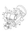
図中、21はマフラ12と該マフラ12が取付けられるフライホイールハウジング10との間に設けられたマフラ支持装置で、該マフラ支持装置21は、従来技術によるマフラ支持装置13に代えて本実施の形態に用いたものである。そして、マフラ支持装置21は、フライホイールハウジング10にマフラ12を取付けて支持するもので、図2ないし図3に示すように、後述のベース部材22と、棒状体23とにより大略構成されている。
【0032】
22は取付部材としてのフライホイールハウジング10に固定されるベース部材で、該ベース部材22は、例えば鋼板材に折曲加工を施すことにより、フライホイールハウジング10に取付けられる取付板22Aと、該取付板22Aの両端側から互いに対面しつつフライホイールハウジング10から離間する方向に突出した突出板22B,22Cとからなる断面コ字状の枠体として形成されている。また、取付板22Aの下端側には、2個のボルト挿通孔22D,22Dが穿設されている。
【0033】
そして、ベース部材22は、各ボルト挿通孔22Dに挿通したボルト15をフライホイールハウジング10に螺着することにより、該フライホイールハウジング10の上端側に固定されている。
【0034】
23はベース部材22の上端側に溶接等によって固着されたマフラ支持部材としての棒状体で、該棒状体23は、マフラ12を支持するものである。ここで、棒状体23は、例えば1本の丸棒材に折曲加工を施すことにより全体としてほぼ四角形の枠状に形成され、マフラ12を構成する筒部12Aの外周面に沿って互いに平行に延びる2本のマフラ支持棒23A,23Aと、これら各マフラ支持棒23A間を連結するV字状の連結棒23Bと、各マフラ支持棒23Aの先端側から斜め下向きに傾斜した傾斜棒23C,23Cとにより構成されている。
【0035】
そして、棒状体23は、連結棒23Bをベース部材22の突出板22Bに溶接等の手段を用いて固着し、各傾斜棒23Cをベース部材22の突出板22Cに溶接等の手段を用いて固着することにより、ベース部材22の上端側に強固に取付けられている。この場合、棒状体23の各マフラ支持棒23Aは、図2ないし図4に示すように、マフラ12を構成する筒部12Aの外周面に沿って互いに平行に延び、かつ、筒部12Aの最下部12A1よりも僅かに上方となる両側部位を該筒部12Aの径方向から挟む位置に配置されている。
【0036】
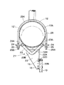
これにより、図4に示すように、棒状体23上にマフラ12を載置したときには、2本のマフラ支持棒23A,23Aが、マフラ12を構成する筒部12Aの最下部12A1を挟んだ状態で該筒部12Aの外周面にそれぞれ線接触するので、これら各マフラ支持棒23Aによって、マフラ12を線接触状態で安定して支持することができる。
【0037】
また、例えば図4中に二点鎖線で示すように、マフラ12よりも小径なマフラ12′を棒状体23上に載置したとしても、各マフラ支持棒23Aが、それぞれマフラ12′の筒部外周面に線接触するので、マフラ12とは外径寸法が異なるマフラ12′をも、各マフラ支持棒23Aによって安定して支持することができる構成となっている。
【0038】
24,24,…は棒状体23を構成する各マフラ支持棒23Aに2個ずつ設けられた合計4個のねじ座で、該ねじ座24は、各マフラ支持棒23Aの長さ方向の両端側に溶接等の手段を用いて固着され、該マフラ支持棒23Aから水平方向に突出している。そして、各ねじ座24の中央部には、後述する締結具25の雄ねじ部25Bが挿通されるボルト挿通孔24Aが穿設されている。
【0039】
25,25はマフラ12の筒部12Aを棒状体23に締結する締結具で、該締結具25は、長さ方向の中央部がマフラ12の筒部12Aとほぼ等しい曲率をもった半円形状の折曲部25Aとなり両端部が雄ねじ部25BとなったU字状の棒状体により構成されている。
【0040】
そして、締結具25は、折曲部25Aをマフラ12の筒部12A外周面に係合させた状態で、各雄ねじ部25Bを、棒状体23(マフラ支持棒23A)に設けた各ねじ座24のボルト挿通孔24Aに挿通し、ねじ座24の下面側に突出した雄ねじ部25Bの先端側にナット26を螺着することにより、マフラ12を棒状体23に締結するものである。
【0041】
本実施の形態によるマフラ支持装置21は上述の如き構成を有するもので、以下、このマフラ支持装置21を用いて、エンジン9のフライホイールハウジング10にマフラ12を取付ける場合について述べる。
【0042】
まず、ベース部材22のボルト挿通孔22Dにボルト15を挿通し、このボルト15をフライホイールハウジング10に螺着することにより、ベース部材22をフライホイールハウジング10に固定する。
【0043】
次に、ベース部材22の上端側に固着された棒状体23上にマフラ12を載置する。この場合、2本のマフラ支持棒23Aは、マフラ12を構成する筒部12Aの最下部12A1を挟んだ状態で該筒部12Aの外周面にそれぞれ線接触し、該マフラ12を線接触状態で支持するので、これら各マフラ支持棒23Aによってマフラ12を安定して支持することができる。
【0044】
この状態で、締結具25の折曲部25Aをマフラ12の筒部12A外周面に係合させ、該締結具25の各雄ねじ部25Bを、棒状体23に設けたねじ座24のボルト挿通孔24Aに挿通する。そして、ねじ座24の下面側に突出した雄ねじ部25Bの先端側にナット26を螺着することにより、マフラ12を棒状体23に締結する。これにより、フライホイールハウジング10に、マフラ支持装置21を用いてマフラ12を確実に取付けて支持することができる。
【0045】
かくして、本実施の形態によるマフラ支持装置21は、棒状体23に2本のマフラ支持棒23A,23Aを設け、この2本のマフラ支持棒23Aが、マフラ12の筒部12A外周面にそれぞれ線接触することにより、該マフラ12を線接触状態で支持する構成となっている。
【0046】
このため、例えば図4中に二点鎖線で示すように、マフラ12よりも外径寸法が小さいマフラ12′を支持する場合でも、2本のマフラ支持棒23A,23Aをマフラ12′の筒部外周面にそれぞれ線接触させることができ、該マフラ12′を各マフラ支持棒23Aによって安定して支持することができる。従って、支持すべきマフラの外径寸法が変化したとしても、このマフラをマフラ支持装置21によって確実に支持することができるので、エンジン9に設けられる複数種類のマフラに対し、マフラ支持装置21を共通化することができる。
【0047】
また、本実施の形態によるマフラ支持装置21は、ベース部材22に設けられるマフラ支持部材としての棒状体23を、2本のマフラ支持棒23A,23Aと、各マフラ支持棒23A間を連結する連結棒23Bと、各マフラ支持棒23Aの先端側に設けられた傾斜棒23C,23Cとにより一体形成している。このため、1本の丸棒材に折曲加工を施すだけで棒状体23を形成することができ、この棒状体23をベース部材22に固着することにより、マフラ支持装置21を容易に製造することができる。
【0048】
次に、図5ないし図7は本発明の第2の実施の形態を示し、本実施の形態の特徴は、マフラ支持部材を、マフラの筒部外周面を線接触状態で支持する板状体によって構成したことにある。なお、本実施の形態では上述した第1の実施の形態と同一の構成要素に同一符号を付し、その説明を省略するものとする。
【0049】
図中、31は第1の実施の形態によるマフラ支持装置21に代えて本実施の形態に用いたマフラ支持装置で、該マフラ支持装置31は、後述のベース部材32と、各板状片33,34とにより大略構成されている。
【0050】
32はフライホイールハウジング10に固定されるベース部材で、該ベース部材32は、例えば鋼板材に折曲加工を施すことにより、フライホイールハウジング10に取付けられる取付板32Aと、該取付板32Aの両端側から互いに対面しつつフライホイールハウジング10から離間する方向に突出した突出板32B,32Cと、これら各突出板32B,32C間を連結し取付板32Aと対面した連結板32Dとにより、長方形の閉断面形状を有する枠体として形成されている。また、取付板32Aの下端側には、2個のボルト挿通孔32E,32Eが穿設されている。
【0051】
そして、ベース部材32は、各ボルト挿通孔32Eに挿通したボルト15をフライホイールハウジング10に螺着することにより、該フライホイールハウジング10の上端側に固定されている。
【0052】
33,33はベース部材32を構成する取付板32Aの上端側に設けられた板状体としての2枚の板状片で、該各板状片33は、マフラ12の軸方向に離間して配置され、後述の各板状片34と共にマフラ12を支持するマフラ支持部材を構成するものである。
【0053】
ここで、板状片33は、ベース部材32の取付板32Aから鉛直方向(上,下方向)に延びた鉛直面33Aと、該鉛直面33Aから斜め上向きに延び上端側がマフラ12から徐々に離間するように傾斜した平坦面33Bと、該平坦面33Bから水平方向に延びた水平面33Cとにより構成されている。
【0054】
そして、鉛直面33Aは、ベース部材32の取付板32Aに溶接等によって固着され、平坦面33Bは、マフラ12を構成する筒部12Aの外周面に線接触するものである。また、水平面33Cには、締結具25の雄ねじ部25Bが挿通されるボルト挿通孔33Dが穿設されている。
【0055】
34,34はベース部材32を構成する連結板32Dの上端側に設けられた板状体としての2枚の板状片で、該各板状片34は、マフラ12の軸方向に離間し、かつ、上述した各板状片33との間で、マフラ12を構成する筒部12Aの最下部12A1よりも僅かに上方となる両側部位を該筒部12Aの径方向から挟む位置に配置されている。
【0056】
ここで、板状片34は、ベース部材32の連結板32Dから鉛直方向(上,下方向)に延びた鉛直面34Aと、該鉛直面34Aから斜め上向きに延び上端側がマフラ12から徐々に離間するように傾斜した平坦面34Bと、該平坦面34Bから水平方向に延びた水平面34Cとにより構成されている。
【0057】
そして、鉛直面34Aは、ベース部材32の連結板32Dに溶接等によって固着され、平坦面34Bは、マフラ12の筒部12A外周面に線接触するものである。また、水平面34Cには、締結具25の雄ねじ部25Bが挿通されるボルト挿通孔34Dが穿設されている。
【0058】
ここで、各板状片33の平坦面33Bと各板状片34の平坦面34Bとは、マフラ12を構成する筒部12Aの外周面に沿って互いに平行に延び、かつ、筒部12Aの最下部12A1を該筒部12Aの径方向から挟む位置に配置されている。
【0059】
これにより、図7に示すように、各板状片33,34上にマフラ12を載置したときには、板状片33の平坦面33Bと板状片34の平坦面34Bとが、それぞれマフラ12の筒部12A外周面に線接触し、該マフラ12を線接触状態で支持するので、これら各板状片33,34によってマフラ12を安定して支持することができる。
【0060】
また、例えば図7中に二点鎖線で示すように、マフラ12よりも小径なマフラ12′を各板状片33,34上に載置したとしても、板状片33の平坦面33Bと板状片34の平坦面34Bとが、それぞれマフラ12の筒部外周面に線接触するので、マフラ12とは外径寸法が異なるマフラ12′をも板状片33,34によって安定して支持することができる構成となっている。
【0061】
本実施の形態によるマフラ支持装置31は上述の如き構成を有するもので、このマフラ支持装置31によってマフラ12を支持する場合には、まず、ベース部材32のボルト挿通孔32Eにボルト15を挿通し、このボルト15をフライホイールハウジング10に螺着することにより、ベース部材32をフライホイールハウジング10に固定する。
【0062】
次に、ベース部材32の上端側に固着された各板状片33,34上にマフラ12を載置する。この場合、各板状片33,34の平坦面33B,34Bは、それぞれマフラ12の筒部12A外周面に線接触し、該マフラ12を線接触状態で支持するので、これら各板状片33,34によってマフラ12を安定して支持することができる。
【0063】
この状態で、締結具25の折曲部25Aをマフラ12の筒部12A外周面に係合させ、該締結具25の各雄ねじ部25Bを、互いに対向する板状片33,34のボルト挿通孔33D,34Dに挿通する。そして、雄ねじ部25Bの先端側にナット26を螺着し、マフラ12を板状片33,34に締結することにより、マフラ12をマフラ支持装置31を用いてエンジン9のフライホイールハウジング10に確実に取付けることができる。
【0064】
この場合、各板状片33,34の平坦面33B,34Bは、マフラ12の筒部12A外周面にそれぞれ線接触する構成となっている。このため、例えば図7中に二点鎖線で示すように、マフラ12よりも外径寸法が小さいマフラ12′を支持する場合でも、各板状片33,34の平坦面33B,34Bが、マフラ12′の筒部外周面にそれぞれ線接触することにより、該マフラ12′を板状片33,34によって安定して支持することができる。従って、支持すべきマフラの外径寸法が変化したとしても、このマフラを共通なマフラ支持装置31によって確実に支持することができる。
【0065】
なお、上述した第1の実施の形態では、マフラ12を構成する筒部12Aの外周面に線接触する2本のマフラ支持棒23A,23Aを、連結棒23B、傾斜棒23Cと共に1本の棒材を用いて一体形成した場合を例に挙げている。しかし、本発明はこれに限るものではなく、例えばコ字状に折曲げた2本のマフラ当接棒を個別に形成し、これらマフラ当接棒をそれぞれベース部材22に固着する構成としてもよい。
【0066】
また、上述した第2の実施の形態では、ベース部材32の取付板32Aに2枚の板状片33を固着すると共に、ベース部材32の連結板32Dに2枚の板状片34を固着した場合を例に挙げている。しかし、本発明はこれに限らず、例えばベース部材32の取付板32Aと連結板32Dとに、マフラ12の軸方向に延びる1枚の板状体をそれぞれ固着する構成としてもよい。また、ベース部材32の取付板32Aに3枚以上の板状片33を固着し、ベース部材32の連結板32Dに3枚以上の板状片34を固着する構成としてもよい。
【0067】
また、上述した各実施の形態では、マフラ12を取付ける取付部材としてエンジン9のフライホイールハウジング10を用いた場合を例示している。しかし、本発明はこれに限らず、例えばエンジン9の周囲に配設された他の部材をマフラ12の取付部材として用いてもよい。
【0068】
さらに、上述した各実施の形態では、油圧ショベル1に搭載されたエンジン9に適用されるマフラ支持装置21,31を例示している。しかし、本発明はこれに限るものではなく、例えば産業機械、自動車等に搭載された原動機に適用してもよい。
【0069】
【発明の効果】
以上詳述した如く、請求項1の発明によれば、マフラを支持するマフラ支持部材を、マフラの筒部外周面を線接触状態で支持する棒状体により構成している。このため、支持すべきマフラの外径寸法が変化したとしても、棒状体をマフラの筒部外周面に確実に線接触させることができる。従って、外径寸法の異なる複数種類のマフラを、共通な棒状体を有するマフラ支持装置によって安定して支持することができる。
【0070】
また、請求項2の発明によれば、棒状体を、マフラの筒部外周面に沿って延びる2本のマフラ支持棒により構成したので、マフラの筒部外周面を2本のマフラ支持棒にそれぞれ線接触させることができ、これら2本のマフラ支持棒によって、外径寸法の異なる複数種類のマフラを安定して支持することができる。
【0071】
また、請求項3の発明によれば、1本の棒材を折曲加工することにより、2本のマフラ支持棒を一体形成する構成としたので、例えば1本の棒材に折曲加工を施して2本のマフラ支持棒を備えたマフラ支持部材を一体形成し、このマフラ支持部材をベース部材に固着することにより、容易にマフラ支持装置を製造することができる。
【0072】
また、請求項4の発明によれば、マフラ支持部材を、マフラの筒部外周面を線接触状態で支持する板状体によって構成したので、支持すべきマフラの外径寸法が変化したとしても、板状体をマフラの筒部外周面に線接触させることにより、該板状体によって外径寸法の異なる複数種類のマフラを安定して支持することができる。
【0073】
さらに、請求項5の発明によれば、板状体を、マフラの軸方向に離間して配置されマフラの筒部外周面に線接触する平坦面をもった複数枚の板状片によって構成している。このため、複数の板状片の平坦面をそれぞれマフラの筒部外周面を線接触させることにより、これら各板状片によって、外径寸法の異なる複数種類のマフラを安定して支持することができる。
【図面の簡単な説明】
【図1】本発明の第1の実施の形態によるマフラ支持装置を、エンジン、マフラ等と共に示す斜視図である。
【図2】第1の実施の形態によるマフラ支持装置のベース部材、棒状体等を示す分解斜視図である。
【図3】マフラ支持装置のベース部材、棒状体、マフラ、フライホイールハウジング等を拡大して示す要部拡大図である。
【図4】マフラ支持装置のベース部材、棒状体、マフラ等を図3中の矢示IV−IV方向からみた断面図である。
【図5】第2の実施の形態によるマフラ支持装置のベース部材、板状片等を示す分解斜視図である。
【図6】マフラ支持装置のベース部材、板状片、マフラ、フライホイールハウジング等を拡大して示す図3と同様の要部拡大図である。
【図7】マフラ支持装置のベース部材、板状片、マフラ等を図6中の矢示VII−VII方向からみた断面図である。
【図8】従来技術によるマフラ支持装置を備えた油圧ショベルを示す一部破断の外観図である。
【図9】従来技術によるマフラ支持装置を、エンジン、マフラ等と共に示す斜視図である。
【図10】従来技術によるマフラ支持装置のベース部材、支持ブラケット等を示す分解斜視図である。
【図11】マフラ支持装置のベース部材、支持ブラケット、マフラ等を示す図4と同様の断面図である。
【符号の説明】
9 エンジン
10 フライホイールハウジング(取付部材)
12,12′ マフラ
12A 筒部
21,31 マフラ支持装置
22,32 ベース部材
23 棒状体(マフラ支持部材)
23A マフラ支持棒
23B 連結棒
25 締結具
33,34 板状片(板状体)
33B,34B 平坦面[0001]
TECHNICAL FIELD OF THE INVENTION
The present invention relates to a muffler support device suitably used for supporting a muffler of a prime mover mounted on, for example, a construction machine, an industrial machine, an automobile, and the like.
[0002]
[Prior art]
2. Description of the Related Art In general, various machines such as construction machines, industrial machines, and automobiles have a prime mover such as an engine as a power source. Construction machines, such as hydraulic shovels and hydraulic cranes, drive a hydraulic pump by an engine and supply hydraulic oil discharged from the hydraulic pump to hydraulic actuators such as a traveling device, a turning device, and a working device to travel downward. The running operation of the body, the turning operation of the upper swing body, the excavation work of earth and sand using the working device, and the like are performed.
[0003]
By the way, a muffler is usually provided in an exhaust pipe of an engine mounted on a hydraulic shovel or the like, and this muffler reduces noise such as exhaust noise generated when the engine is operated (for example, Patent Document 1). reference).
[0004]
[Patent Document 1]
JP-A-11-36857
[0005]
This type of muffler is usually attached to an engine or the like via a muffler support device. Hereinafter, a case where the conventional muffler support device is applied to a hydraulic excavator will be described with reference to FIGS. This will be described with reference to FIG.
[0006]
In the figure,
[0007]
Here, the
[0008]
[0009]
[0010]
[0011]
[0012]
[0013]
Here, the
[0014]
[0015]
Then, the
[0016]
The
[0017]
First, the
[0018]
The
[0019]
[Problems to be solved by the invention]
However, in the
[0020]
For this reason, when the
[0021]
The present invention has been made in view of the above-described problems of the related art, and has an object to provide a muffler supporting device capable of stably supporting the muffler even when the outer diameter of the muffler changes. And
[0022]
[Means for Solving the Problems]
In order to solve the above-described problem, the present invention provides a base member provided between a cylindrical muffler and a mounting member to which the muffler is mounted, the base member fixed to the mounting member, and an outer periphery of the muffler provided on the base member. The present invention is applied to a muffler support device including a muffler support member that supports the muffler by contacting the surface.
[0023]
The feature of the first aspect of the present invention is that the muffler support member is constituted by a rod-shaped member that supports the outer peripheral surface of the cylindrical portion of the muffler in a line contact state. With this configuration, the muffler can be supported by the rod-shaped body while the rod-shaped body is in line contact with the outer peripheral surface of the cylindrical portion of the muffler. Thus, a plurality of types of mufflers having different outer diameters can be stably supported by the common muffler support device.
[0024]
The invention according to
[0025]
According to a third aspect of the present invention, the two muffler support rods are integrally formed by bending one rod material. With this configuration, it is possible to integrally form a muffler support member having two muffler support rods, for example, only by bending one bar material, and use this muffler support member as a base member. Just by fixing, the muffler support device can be easily manufactured.
[0026]
According to a fourth aspect of the present invention, a base member is provided between a cylindrical muffler and a mounting member to which the muffler is mounted, and is fixed to the mounting member, and is in contact with an outer peripheral surface of the muffler provided on the base member. In the muffler support device constituted by the muffler support member for supporting the muffler, the muffler support member is characterized in that the muffler support member is constituted by a plate-like body which supports the outer peripheral surface of the cylindrical portion of the muffler in a line contact state.
[0027]
With this configuration, even if the outer diameter of the muffler to be supported changes, the muffler is supported by the plate-like body while the plate-like body is in line contact with the outer peripheral surface of the cylindrical portion of the muffler. be able to.
[0028]
The invention according to claim 5 is that the plate-like body is constituted by a plurality of plate-like pieces having a flat surface which is arranged in the axial direction of the muffler and is in line contact with the outer peripheral surface of the cylindrical portion of the muffler. With this configuration, a plurality of types of mufflers having different outer diameters can be reliably formed by these plate-shaped pieces in a state where the outer peripheral surface of the muffler is in line contact with the flat surface of each of the plurality of plate-shaped pieces. Can be supported.
[0029]
BEST MODE FOR CARRYING OUT THE INVENTION
Hereinafter, an embodiment of a muffler support device according to the present invention applied to an engine mounted on a hydraulic shovel will be described in detail with reference to FIGS. 1 to 7.
[0030]
First, FIG. 1 to FIG. 4 show a first embodiment of the present invention. In the present embodiment, the same components as those of the above-described related art are denoted by the same reference numerals, and description thereof will be omitted.
[0031]
In the figure,
[0032]
[0033]
The
[0034]
[0035]
The
[0036]
Thereby, as shown in FIG. 4, when the
[0037]
Also, for example, as shown by a two-dot chain line in FIG. 4, even if a
[0038]
24, 24,... Are a total of four screw seats provided two by two on each
[0039]
25, 25 are fasteners for fastening the
[0040]
Then, the
[0041]
The
[0042]
First, the
[0043]
Next, the
[0044]
In this state, the
[0045]
Thus, in the
[0046]
Therefore, for example, as shown by a two-dot chain line in FIG. 4, even when the muffler 12 'having an outer diameter smaller than the
[0047]
Further, the
[0048]
Next, FIGS. 5 to 7 show a second embodiment of the present invention. The feature of this embodiment is that a plate-like member for supporting a muffler support member in a line contact state with the outer peripheral surface of a cylindrical portion of a muffler. It is constituted by. In this embodiment, the same components as those in the above-described first embodiment are denoted by the same reference numerals, and description thereof will be omitted.
[0049]
In the figure,
[0050]
[0051]
The
[0052]
[0053]
Here, the plate-
[0054]
The
[0055]
[0056]
Here, the plate-shaped
[0057]
The
[0058]
Here, the
[0059]
Thereby, as shown in FIG. 7, when the
[0060]
For example, as shown by a two-dot chain line in FIG. 7, even if a
[0061]
The
[0062]
Next, the
[0063]
In this state, the
[0064]
In this case, the
[0065]
In the first embodiment described above, the two
[0066]
In the above-described second embodiment, two plate-shaped
[0067]
Further, in each of the above-described embodiments, the case where the
[0068]
Further, in each of the above-described embodiments, the
[0069]
【The invention's effect】
As described in detail above, according to the first aspect of the present invention, the muffler support member that supports the muffler is formed of a rod that supports the outer peripheral surface of the cylindrical portion of the muffler in a line contact state. For this reason, even if the outer diameter of the muffler to be supported changes, the rod-shaped body can be reliably brought into line contact with the outer peripheral surface of the cylindrical portion of the muffler. Therefore, a plurality of types of mufflers having different outer diameters can be stably supported by the muffler support device having a common rod-shaped body.
[0070]
According to the second aspect of the present invention, since the rod-shaped body is constituted by the two muffler support rods extending along the outer peripheral surface of the muffler cylinder, the outer peripheral surface of the muffler cylinder is replaced with the two muffler support rods. The two muffler support rods can make line contact with each other, and can stably support a plurality of types of mufflers having different outer diameters.
[0071]
According to the third aspect of the present invention, the two muffler support rods are integrally formed by bending one bar, so that, for example, one bar is bent. The muffler support member provided with the two muffler support rods is integrally formed, and the muffler support member is fixed to the base member, whereby the muffler support device can be easily manufactured.
[0072]
According to the invention of claim 4, since the muffler support member is formed by the plate-like member that supports the outer peripheral surface of the muffler in a line contact state, even if the outer diameter of the muffler to be supported changes. By bringing the plate into line contact with the outer peripheral surface of the cylindrical portion of the muffler, a plurality of types of mufflers having different outer diameters can be stably supported by the plate.
[0073]
Furthermore, according to the fifth aspect of the present invention, the plate-like body is constituted by a plurality of plate-like pieces having a flat surface which is arranged in the axial direction of the muffler and is in line contact with the outer peripheral surface of the cylindrical portion of the muffler. ing. Therefore, by bringing the flat surfaces of the plurality of plate-shaped pieces into line contact with the outer peripheral surface of the cylindrical portion of the muffler, each of the plate-shaped pieces can stably support a plurality of types of mufflers having different outer diameters. it can.
[Brief description of the drawings]
FIG. 1 is a perspective view showing a muffler support device according to a first embodiment of the present invention, together with an engine, a muffler, and the like.
FIG. 2 is an exploded perspective view showing a base member, a rod, and the like of the muffler support device according to the first embodiment.
FIG. 3 is an enlarged view of a main part showing a base member, a rod-shaped body, a muffler, a flywheel housing and the like of the muffler support device in an enlarged manner.
4 is a cross-sectional view of a base member, a rod-shaped body, a muffler, and the like of the muffler support device, as viewed in a direction indicated by arrows IV-IV in FIG.
FIG. 5 is an exploded perspective view showing a base member, a plate-like piece, and the like of a muffler support device according to a second embodiment.
FIG. 6 is an enlarged view of a main part similar to FIG. 3, showing an enlarged view of a base member, a plate-like piece, a muffler, a flywheel housing, and the like of the muffler support device.
7 is a cross-sectional view of a base member, a plate-like piece, a muffler, and the like of the muffler support device, as viewed in a direction indicated by arrows VII-VII in FIG.
FIG. 8 is a partially broken external view showing a hydraulic excavator provided with a muffler support device according to the related art.
FIG. 9 is a perspective view showing a muffler support device according to the related art together with an engine, a muffler, and the like.
FIG. 10 is an exploded perspective view showing a base member, a support bracket, and the like of a muffler support device according to the related art.
FIG. 11 is a sectional view similar to FIG. 4, showing a base member, a support bracket, a muffler, and the like of the muffler support device.
[Explanation of symbols]
9 Engine
10. Flywheel housing (mounting member)
12,12 'muffler
12A cylinder
21,31 Muffler support device
22, 32 Base member
23 rods (muffler support members)
23A Muffler support rod
23B Connecting rod
25 Fastener
33, 34 plate-shaped piece (plate-shaped body)
33B, 34B Flat surface
Claims (5)
前記マフラ支持部材は、前記マフラの筒部外周面を線接触状態で支持する棒状体により構成したことを特徴とするマフラ支持装置。The muffler is supported by being provided between a cylindrical muffler and a mounting member to which the muffler is mounted and fixed to the mounting member, and abutting on an outer peripheral surface of the muffler provided on the base member. Muffler support device configured by a muffler support member to
The muffler support device is characterized in that the muffler support member is constituted by a rod-shaped body that supports the outer peripheral surface of the cylindrical portion of the muffler in a line contact state.
前記マフラ支持部材は、前記マフラの筒部外周面を線接触状態で支持する板状体により構成したことを特徴とするマフラ支持装置。The muffler is supported by being provided between a cylindrical muffler and a mounting member to which the muffler is mounted and fixed to the mounting member, and abutting on an outer peripheral surface of the muffler provided on the base member. Muffler support device configured by a muffler support member to
The muffler support device is characterized in that the muffler support member is formed of a plate-like body that supports the outer peripheral surface of the cylindrical portion of the muffler in a line contact state.
Priority Applications (1)
| Application Number | Priority Date | Filing Date | Title |
|---|---|---|---|
| JP2003140998A JP2004340114A (en) | 2003-05-19 | 2003-05-19 | Muffler support device |
Applications Claiming Priority (1)
| Application Number | Priority Date | Filing Date | Title |
|---|---|---|---|
| JP2003140998A JP2004340114A (en) | 2003-05-19 | 2003-05-19 | Muffler support device |
Publications (1)
| Publication Number | Publication Date |
|---|---|
| JP2004340114A true JP2004340114A (en) | 2004-12-02 |
Family
ID=33529538
Family Applications (1)
| Application Number | Title | Priority Date | Filing Date |
|---|---|---|---|
| JP2003140998A Pending JP2004340114A (en) | 2003-05-19 | 2003-05-19 | Muffler support device |
Country Status (1)
| Country | Link |
|---|---|
| JP (1) | JP2004340114A (en) |
Cited By (32)
| Publication number | Priority date | Publication date | Assignee | Title |
|---|---|---|---|---|
| JP2008196315A (en) * | 2007-02-08 | 2008-08-28 | Iseki & Co Ltd | Diesel engine |
| WO2009142058A1 (en) * | 2008-05-22 | 2009-11-26 | 日立建機株式会社 | Construction machine |
| WO2010032646A1 (en) * | 2008-09-18 | 2010-03-25 | ヤンマー株式会社 | Engine device |
| WO2010032647A1 (en) * | 2008-09-18 | 2010-03-25 | ヤンマー株式会社 | Engine device |
| JP2010071176A (en) * | 2008-09-18 | 2010-04-02 | Yanmar Co Ltd | Engine device |
| JP2010106582A (en) * | 2008-10-30 | 2010-05-13 | Sumitomo (Shi) Construction Machinery Co Ltd | Bracket-and-flange integrated type engine assembly component of construction machinery |
| JP2010106694A (en) * | 2008-10-28 | 2010-05-13 | Yanmar Co Ltd | Engine device to be mounted on working vehicle |
| WO2010106869A1 (en) * | 2009-03-16 | 2010-09-23 | ヤンマー株式会社 | Engine device |
| WO2010110242A1 (en) * | 2009-03-26 | 2010-09-30 | 株式会社小松製作所 | Exhaust gas purifying device for internal combustion engine |
| CN102072054A (en) * | 2011-01-28 | 2011-05-25 | 襄樊康豪机电工程有限公司 | Novel layout structure of air filter assembly of engine |
| KR20110058816A (en) * | 2008-09-18 | 2011-06-01 | 얀마 가부시키가이샤 | Exhaust gas purifying device |
| JP2011163339A (en) * | 2010-01-14 | 2011-08-25 | Kubota Corp | Engine with exhaust gas treatment device |
| CN102174910A (en) * | 2011-01-28 | 2011-09-07 | 襄樊康豪机电工程有限公司 | Marine engine water-air intercooler |
| US20110219757A1 (en) * | 2010-03-11 | 2011-09-15 | Hitachi Construction Machinery Co., Ltd. | Muffler Draining Apparatus for Working Machine |
| JP2011241570A (en) * | 2010-05-17 | 2011-12-01 | Hitachi Constr Mach Co Ltd | Construction machinery |
| JP2012184771A (en) * | 2012-06-08 | 2012-09-27 | Yanmar Co Ltd | Engine device |
| CN102700402A (en) * | 2012-05-31 | 2012-10-03 | 芜湖市三和汽车部件制造有限公司 | Exhaust pipe hanging hook assembly |
| JP2013064408A (en) * | 2012-12-10 | 2013-04-11 | Yanmar Co Ltd | Engine device |
| JP2013151946A (en) * | 2013-05-16 | 2013-08-08 | Yanmar Co Ltd | Engine device |
| JP2013189981A (en) * | 2013-05-27 | 2013-09-26 | Yanmar Co Ltd | Engine device for installation on working vehicle |
| JP2014029152A (en) * | 2013-08-19 | 2014-02-13 | Yanmar Co Ltd | Engine device mounted on work vehicle |
| JP2014077448A (en) * | 2013-12-10 | 2014-05-01 | Yanmar Co Ltd | Engine device |
| JP2014111946A (en) * | 2014-03-26 | 2014-06-19 | Yanmar Co Ltd | Engine device for work vehicle mounting |
| US8764866B2 (en) | 2008-09-18 | 2014-07-01 | Yanmar Co., Ltd. | Engine device |
| JP2014159811A (en) * | 2014-03-26 | 2014-09-04 | Yanmar Co Ltd | Engine device mounted on work vehicle |
| JP2015045337A (en) * | 2014-11-12 | 2015-03-12 | ヤンマー株式会社 | Engine device |
| EP2333260A4 (en) * | 2008-09-18 | 2015-10-14 | Yanmar Co Ltd | Engine device |
| JP2016180410A (en) * | 2016-07-04 | 2016-10-13 | ヤンマー株式会社 | Work vehicle |
| JP2016205398A (en) * | 2016-07-04 | 2016-12-08 | ヤンマー株式会社 | Combine harvester |
| JP2019166889A (en) * | 2018-03-22 | 2019-10-03 | 株式会社クボタ | Paddy work machine |
| CN112096499A (en) * | 2019-06-17 | 2020-12-18 | 埃贝斯佩歇排气技术有限公司 | Component for an exhaust system of an internal combustion engine |
| EP4001605A1 (en) * | 2020-11-17 | 2022-05-25 | Iseki & Co., Ltd. | Riding lawn mower |
-
2003
- 2003-05-19 JP JP2003140998A patent/JP2004340114A/en active Pending
Cited By (67)
| Publication number | Priority date | Publication date | Assignee | Title |
|---|---|---|---|---|
| JP2008196315A (en) * | 2007-02-08 | 2008-08-28 | Iseki & Co Ltd | Diesel engine |
| CN102036846A (en) * | 2008-05-22 | 2011-04-27 | 日立建机株式会社 | Construction machine |
| WO2009142058A1 (en) * | 2008-05-22 | 2009-11-26 | 日立建機株式会社 | Construction machine |
| EP2287030A4 (en) * | 2008-05-22 | 2018-04-04 | Hitachi Construction Machinery Co., Ltd | Construction machine |
| CN102036846B (en) * | 2008-05-22 | 2013-11-06 | 日立建机株式会社 | Construction machine |
| US8418448B2 (en) | 2008-05-22 | 2013-04-16 | Hitachi Construction Machinery Co., Ltd. | Exhaust gas treatment device for construction machine |
| JP5172956B2 (en) * | 2008-05-22 | 2013-03-27 | 日立建機株式会社 | Construction machinery |
| CN102159817A (en) * | 2008-09-18 | 2011-08-17 | 洋马株式会社 | Engine device |
| US8764866B2 (en) | 2008-09-18 | 2014-07-01 | Yanmar Co., Ltd. | Engine device |
| US8683788B2 (en) * | 2008-09-18 | 2014-04-01 | Yanmar Co., Ltd. | Exhaust gas purifying device |
| JP2010071175A (en) * | 2008-09-18 | 2010-04-02 | Yanmar Co Ltd | Engine device |
| WO2010032647A1 (en) * | 2008-09-18 | 2010-03-25 | ヤンマー株式会社 | Engine device |
| KR20110058816A (en) * | 2008-09-18 | 2011-06-01 | 얀마 가부시키가이샤 | Exhaust gas purifying device |
| EP2333263A1 (en) * | 2008-09-18 | 2011-06-15 | Yanmar Co., Ltd. | Engine device |
| US20110154809A1 (en) * | 2008-09-18 | 2011-06-30 | Yanmar Co., Ltd. | Engine device |
| US20110167807A1 (en) * | 2008-09-18 | 2011-07-14 | Masataka Mitsuda | Exhaust gas purifying device |
| EP2333260A4 (en) * | 2008-09-18 | 2015-10-14 | Yanmar Co Ltd | Engine device |
| CN102159809A (en) * | 2008-09-18 | 2011-08-17 | 洋马株式会社 | Engine device |
| EP2333263A4 (en) * | 2008-09-18 | 2015-04-22 | Yanmar Co Ltd | Engine device |
| WO2010032646A1 (en) * | 2008-09-18 | 2010-03-25 | ヤンマー株式会社 | Engine device |
| KR101618167B1 (en) | 2008-09-18 | 2016-05-18 | 얀마 가부시키가이샤 | Engine device |
| KR101583539B1 (en) | 2008-09-18 | 2016-01-08 | 얀마 가부시키가이샤 | Exhaust gas purifying device |
| JP2010071176A (en) * | 2008-09-18 | 2010-04-02 | Yanmar Co Ltd | Engine device |
| EP2336520A4 (en) * | 2008-09-18 | 2015-10-14 | Yanmar Co Ltd | Engine device |
| US9140154B2 (en) | 2008-09-18 | 2015-09-22 | Yanmar Co., Ltd. | Engine device |
| JP2010106694A (en) * | 2008-10-28 | 2010-05-13 | Yanmar Co Ltd | Engine device to be mounted on working vehicle |
| JP2010106582A (en) * | 2008-10-30 | 2010-05-13 | Sumitomo (Shi) Construction Machinery Co Ltd | Bracket-and-flange integrated type engine assembly component of construction machinery |
| WO2010106869A1 (en) * | 2009-03-16 | 2010-09-23 | ヤンマー株式会社 | Engine device |
| CN103277180A (en) * | 2009-03-16 | 2013-09-04 | 洋马株式会社 | Engine device |
| CN102356223B (en) * | 2009-03-16 | 2014-07-02 | 洋马株式会社 | Engine device |
| CN103277180B (en) * | 2009-03-16 | 2015-09-23 | 洋马株式会社 | Engine device |
| CN102356223A (en) * | 2009-03-16 | 2012-02-15 | 洋马株式会社 | Engine device |
| CN103982286A (en) * | 2009-03-16 | 2014-08-13 | 洋马株式会社 | Combine-harvester |
| CN103982296A (en) * | 2009-03-16 | 2014-08-13 | 洋马株式会社 | Engine device carried by working vehicle |
| JP4972228B2 (en) * | 2009-03-26 | 2012-07-11 | 株式会社小松製作所 | Exhaust gas purification device for internal combustion engine |
| US8943813B2 (en) | 2009-03-26 | 2015-02-03 | Komatsu Ltd. | Exhaust gas purifying device for internal combustion engine |
| JPWO2010110242A1 (en) * | 2009-03-26 | 2012-09-27 | 株式会社小松製作所 | Exhaust gas purification device for internal combustion engine |
| WO2010110242A1 (en) * | 2009-03-26 | 2010-09-30 | 株式会社小松製作所 | Exhaust gas purifying device for internal combustion engine |
| US20120011833A1 (en) * | 2009-03-26 | 2012-01-19 | Komatsu Ltd. | Exhaust Gas Purifying Device for Internal Combustion Engine |
| CN102365431A (en) * | 2009-03-26 | 2012-02-29 | 株式会社小松制作所 | Exhaust gas purifying device for internal combustion engine |
| US8991162B2 (en) | 2010-01-14 | 2015-03-31 | Kubota Corporation | Engine with exhaust gas treatment apparatus |
| JP2011163339A (en) * | 2010-01-14 | 2011-08-25 | Kubota Corp | Engine with exhaust gas treatment device |
| JP2011190689A (en) * | 2010-03-11 | 2011-09-29 | Hitachi Constr Mach Co Ltd | Muffler draining device for working machine |
| US20110219757A1 (en) * | 2010-03-11 | 2011-09-15 | Hitachi Construction Machinery Co., Ltd. | Muffler Draining Apparatus for Working Machine |
| CN102191986A (en) * | 2010-03-11 | 2011-09-21 | 日立建机株式会社 | Muffler draining apparatus for working machine |
| JP2011241570A (en) * | 2010-05-17 | 2011-12-01 | Hitachi Constr Mach Co Ltd | Construction machinery |
| CN102072054A (en) * | 2011-01-28 | 2011-05-25 | 襄樊康豪机电工程有限公司 | Novel layout structure of air filter assembly of engine |
| CN102174910A (en) * | 2011-01-28 | 2011-09-07 | 襄樊康豪机电工程有限公司 | Marine engine water-air intercooler |
| CN102700402A (en) * | 2012-05-31 | 2012-10-03 | 芜湖市三和汽车部件制造有限公司 | Exhaust pipe hanging hook assembly |
| JP2012184771A (en) * | 2012-06-08 | 2012-09-27 | Yanmar Co Ltd | Engine device |
| JP2013064408A (en) * | 2012-12-10 | 2013-04-11 | Yanmar Co Ltd | Engine device |
| JP2013151946A (en) * | 2013-05-16 | 2013-08-08 | Yanmar Co Ltd | Engine device |
| JP2013189981A (en) * | 2013-05-27 | 2013-09-26 | Yanmar Co Ltd | Engine device for installation on working vehicle |
| JP2014029152A (en) * | 2013-08-19 | 2014-02-13 | Yanmar Co Ltd | Engine device mounted on work vehicle |
| JP2014077448A (en) * | 2013-12-10 | 2014-05-01 | Yanmar Co Ltd | Engine device |
| JP2014159811A (en) * | 2014-03-26 | 2014-09-04 | Yanmar Co Ltd | Engine device mounted on work vehicle |
| JP2014111946A (en) * | 2014-03-26 | 2014-06-19 | Yanmar Co Ltd | Engine device for work vehicle mounting |
| JP2015045337A (en) * | 2014-11-12 | 2015-03-12 | ヤンマー株式会社 | Engine device |
| JP2016180410A (en) * | 2016-07-04 | 2016-10-13 | ヤンマー株式会社 | Work vehicle |
| JP2016205398A (en) * | 2016-07-04 | 2016-12-08 | ヤンマー株式会社 | Combine harvester |
| JP6991086B2 (en) | 2018-03-22 | 2022-01-12 | 株式会社クボタ | Paddy field work machine |
| JP2019166889A (en) * | 2018-03-22 | 2019-10-03 | 株式会社クボタ | Paddy work machine |
| CN112096499A (en) * | 2019-06-17 | 2020-12-18 | 埃贝斯佩歇排气技术有限公司 | Component for an exhaust system of an internal combustion engine |
| EP3754165A1 (en) * | 2019-06-17 | 2020-12-23 | Eberspächer Exhaust Technology GmbH | Component for an exhaust gas system of a combustion engine |
| CN112096499B (en) * | 2019-06-17 | 2022-09-06 | 普瑞姆有限公司 | Component for an exhaust system of an internal combustion engine and exhaust system for an internal combustion engine |
| US11702968B2 (en) | 2019-06-17 | 2023-07-18 | Purem GmbH | Component for an exhaust system of an internal combustion engine |
| EP4001605A1 (en) * | 2020-11-17 | 2022-05-25 | Iseki & Co., Ltd. | Riding lawn mower |
Similar Documents
| Publication | Publication Date | Title |
|---|---|---|
| JP2004340114A (en) | Muffler support device | |
| JP5501112B2 (en) | Work vehicle | |
| JP2006328764A (en) | Turning frame of construction machinery | |
| JP2012067580A (en) | Work device of construction machine | |
| JP4136752B2 (en) | Muffler mounting device for construction machinery | |
| JP6449096B2 (en) | Front loader frame, front loader including front loader frame, and work vehicle including front loader | |
| JP5411173B2 (en) | Construction machine swivel frame | |
| US10100488B2 (en) | Front loader, support frame for a front loader and method | |
| JP4387893B2 (en) | Construction machinery cab | |
| JP4474222B2 (en) | Swivel frame structure for construction machinery | |
| JP3691750B2 (en) | Swivel work machine | |
| JP4060755B2 (en) | Hose clamp device | |
| JP2009209575A (en) | Construction equipment | |
| JPH10331657A (en) | Circular construction machine | |
| JP6832305B2 (en) | Construction machinery | |
| JP5949076B2 (en) | Work machine | |
| JP2002188176A (en) | Construction equipment | |
| JP2005016019A (en) | Revolving frame for construction machine | |
| JP2011105065A (en) | Construction machine | |
| JP5100732B2 (en) | Swing frame of swivel work machine | |
| JP2003276653A (en) | Front guard device for tractor | |
| JP6411973B2 (en) | Small excavator | |
| JP2016137760A (en) | Engine support structure of construction machine | |
| JP5798097B2 (en) | Swivel construction machine | |
| JP2003278179A (en) | Reinforcing structure for boom pivotal support part |
Legal Events
| Date | Code | Title | Description |
|---|---|---|---|
| A621 | Written request for application examination |
Free format text: JAPANESE INTERMEDIATE CODE: A621 Effective date: 20051121 |
|
| A977 | Report on retrieval |
Free format text: JAPANESE INTERMEDIATE CODE: A971007 Effective date: 20080717 |
|
| A131 | Notification of reasons for refusal |
Free format text: JAPANESE INTERMEDIATE CODE: A131 Effective date: 20080812 |
|
| A02 | Decision of refusal |
Free format text: JAPANESE INTERMEDIATE CODE: A02 Effective date: 20090113 |