JP2004316924A - Dynamic pressure-type oil-impregnated sintered bearing unit - Google Patents
Dynamic pressure-type oil-impregnated sintered bearing unit Download PDFInfo
- Publication number
- JP2004316924A JP2004316924A JP2004219142A JP2004219142A JP2004316924A JP 2004316924 A JP2004316924 A JP 2004316924A JP 2004219142 A JP2004219142 A JP 2004219142A JP 2004219142 A JP2004219142 A JP 2004219142A JP 2004316924 A JP2004316924 A JP 2004316924A
- Authority
- JP
- Japan
- Prior art keywords
- bearing
- dynamic pressure
- oil
- impregnated
- bearing surface
- Prior art date
- Legal status (The legal status is an assumption and is not a legal conclusion. Google has not performed a legal analysis and makes no representation as to the accuracy of the status listed.)
- Pending
Links
- 230000002093 peripheral effect Effects 0.000 claims description 62
- 239000002184 metal Substances 0.000 claims description 8
- 229910052751 metal Inorganic materials 0.000 claims description 8
- 230000009471 action Effects 0.000 claims description 7
- 230000000694 effects Effects 0.000 abstract description 5
- 239000003921 oil Substances 0.000 description 50
- 239000007769 metal material Substances 0.000 description 29
- 239000000463 material Substances 0.000 description 24
- 238000000465 moulding Methods 0.000 description 19
- 238000000034 method Methods 0.000 description 11
- 238000004513 sizing Methods 0.000 description 11
- 238000003825 pressing Methods 0.000 description 9
- 239000010687 lubricating oil Substances 0.000 description 7
- 230000008859 change Effects 0.000 description 6
- 230000001050 lubricating effect Effects 0.000 description 6
- 230000003287 optical effect Effects 0.000 description 6
- 239000004519 grease Substances 0.000 description 5
- 239000000314 lubricant Substances 0.000 description 5
- RYGMFSIKBFXOCR-UHFFFAOYSA-N Copper Chemical compound [Cu] RYGMFSIKBFXOCR-UHFFFAOYSA-N 0.000 description 4
- 239000011148 porous material Substances 0.000 description 4
- 230000008569 process Effects 0.000 description 4
- 238000012545 processing Methods 0.000 description 4
- XEEYBQQBJWHFJM-UHFFFAOYSA-N Iron Chemical compound [Fe] XEEYBQQBJWHFJM-UHFFFAOYSA-N 0.000 description 3
- 229910052802 copper Inorganic materials 0.000 description 3
- 239000010949 copper Substances 0.000 description 3
- 238000010438 heat treatment Methods 0.000 description 3
- 229920005989 resin Polymers 0.000 description 3
- 239000011347 resin Substances 0.000 description 3
- 238000004140 cleaning Methods 0.000 description 2
- 238000005245 sintering Methods 0.000 description 2
- 208000017227 ADan amyloidosis Diseases 0.000 description 1
- 229910001018 Cast iron Inorganic materials 0.000 description 1
- 241000252203 Clupea harengus Species 0.000 description 1
- 201000000194 ITM2B-related cerebral amyloid angiopathy 2 Diseases 0.000 description 1
- 239000000853 adhesive Substances 0.000 description 1
- 230000001070 adhesive effect Effects 0.000 description 1
- 229910045601 alloy Inorganic materials 0.000 description 1
- 239000000956 alloy Substances 0.000 description 1
- 239000002199 base oil Substances 0.000 description 1
- 238000005452 bending Methods 0.000 description 1
- 230000008901 benefit Effects 0.000 description 1
- 230000015572 biosynthetic process Effects 0.000 description 1
- 210000000988 bone and bone Anatomy 0.000 description 1
- 239000000919 ceramic Substances 0.000 description 1
- 229910010293 ceramic material Inorganic materials 0.000 description 1
- 238000000748 compression moulding Methods 0.000 description 1
- 230000007423 decrease Effects 0.000 description 1
- 230000003111 delayed effect Effects 0.000 description 1
- 230000006866 deterioration Effects 0.000 description 1
- 208000037265 diseases, disorders, signs and symptoms Diseases 0.000 description 1
- 230000005489 elastic deformation Effects 0.000 description 1
- 239000013013 elastic material Substances 0.000 description 1
- 238000010304 firing Methods 0.000 description 1
- 238000005187 foaming Methods 0.000 description 1
- 235000019514 herring Nutrition 0.000 description 1
- 230000001771 impaired effect Effects 0.000 description 1
- 238000005470 impregnation Methods 0.000 description 1
- 229910052742 iron Inorganic materials 0.000 description 1
- 238000005339 levitation Methods 0.000 description 1
- 238000005461 lubrication Methods 0.000 description 1
- 238000003754 machining Methods 0.000 description 1
- 238000012856 packing Methods 0.000 description 1
- 239000004033 plastic Substances 0.000 description 1
- 238000012805 post-processing Methods 0.000 description 1
- 239000000843 powder Substances 0.000 description 1
- 230000009467 reduction Effects 0.000 description 1
- 230000002940 repellent Effects 0.000 description 1
- 239000005871 repellent Substances 0.000 description 1
- 230000000717 retained effect Effects 0.000 description 1
- 238000005096 rolling process Methods 0.000 description 1
- 229920003002 synthetic resin Polymers 0.000 description 1
- 239000000057 synthetic resin Substances 0.000 description 1
- 210000001519 tissue Anatomy 0.000 description 1
- 238000012546 transfer Methods 0.000 description 1
- 238000013022 venting Methods 0.000 description 1
Images


Landscapes
- Sliding-Contact Bearings (AREA)
- Motor Or Generator Frames (AREA)
- Connection Of Motors, Electrical Generators, Mechanical Devices, And The Like (AREA)
Abstract
Description
本発明は、動圧型焼結含油軸受ユニットに関する。この動圧型焼結含油軸受は、特に情報機器分野で用いられる、DVD−ROM、DVD−RAMなどの光ディスク装置、MOなどの光磁気ディスク装置、HiFD、Zipなどの高容量FDD(フロッピー(登録商標)ディスクドライブ)、HDDなどの磁気ディスク装置のディスクドライブ用軸受、あるいはLBPなどのポリゴンスキャナモータ用軸受に適しており、特に薄型モータ用の軸受として好適である。 The present invention relates to a hydrodynamic sintered oil-impregnated bearing unit. This hydrodynamic sintered oil-impregnated bearing is used particularly in the field of information equipment, such as optical disk devices such as DVD-ROM and DVD-RAM, magneto-optical disk devices such as MO, and high-capacity FDDs (Floppy (registered trademark) such as HiFD and Zip). It is suitable for a disk drive), a disk drive bearing of a magnetic disk device such as an HDD, or a bearing for a polygon scanner motor such as an LBP, and particularly suitable as a bearing for a thin motor.
上記情報機器類のスピンドルモータには、さらなる高回転精度化、高速化、低コスト化、低騒音化などが求められているが、これらの要求性能を決定づける構成要素の一つにモータのスピンドルを支持する軸受がある。近年では、この種の軸受として、焼結金属製の軸受本体に潤滑油または潤滑グリースを含浸させ、軸受面に設けた動圧溝の動圧効果で軸受隙間に潤滑油膜を形成してスピンドルを非接触支持する、いわゆる動圧型焼結含油軸受の使用が検討されている。この動圧型焼結含油軸受は、低コストでありながら高い回転精度、低騒音等の特徴を有し、上記要求性能にも十分に対応できると考えられる。 The spindle motors of the above information equipment are required to have higher rotational accuracy, higher speed, lower cost, lower noise, etc., and one of the components that determine these required performance is the motor spindle. There are bearings to support. In recent years, as a bearing of this kind, a sintered metal bearing body is impregnated with lubricating oil or lubricating grease, and a dynamic oil pressure effect provided by a dynamic pressure groove provided on the bearing surface forms a lubricating oil film in the bearing gap to form a spindle. The use of a so-called dynamic pressure type oil-impregnated bearing that supports in a non-contact manner is being studied. This hydrodynamic sintered oil-impregnated bearing has features such as high rotational accuracy and low noise while being low in cost, and is considered to be able to sufficiently meet the required performance described above.
図12は、動圧型焼結含油軸受1を用いた光ディスク装置のスピンドルモータの一例である。図示のように、このスピンドルモータは、動圧型焼結含油軸受1、軸受を収容するハウジング2、軸受1に支持された回転軸3、光ディスク4を支持固定するターンテーブル5およびクランパ6、ステータ7aおよびロータ7bからなるモータ部Mを具備しており、ステータ7aへの通電により、ロータ7bと一体になったロータケース8、ターンテーブル5、光ディスク4、クランパ6を一体回転させる構造である。
FIG. 12 shows an example of a spindle motor of an optical disc device using the hydrodynamic sintered oil-impregnated bearing 1. As shown in the figure, the spindle motor includes a dynamic pressure type sintered oil-impregnated bearing 1, a
動圧型焼結含油軸受1は、図13に示すように、厚肉円筒状に形成された多孔質の軸受本体1aと、潤滑油または潤滑グリースの含浸によって軸受本体1aの細孔内に保有された油とで構成される。軸受本体1aの内周面には、回転軸3の外周面と軸受隙間を介して対向する一対の軸受面1bが軸方向に離隔形成され、両軸受面1bに軸方向に対して傾斜した動圧溝1cが形成されている。
As shown in FIG. 13, the dynamic pressure type sintered oil-impregnated bearing 1 is held in the pores of the bearing
図12および図14に示すように、回転軸3のスラスト荷重は、ハウジング2の底部に設けられたスラスト軸受9で支持される。スラスト軸受9としては、球面状の軸端を、ハウジング2底部に設けた潤滑性に富む樹脂製ワッシャ9aに摺動させる構造(いわゆるピボット軸受)が一般的である(特許文献1参照)。
しかし、ピボット軸受では、ワッシャ9aの弾性変形や塑性変形、あるいは摩耗による変形等によってワッシャに窪みができ、軸の位置が時間経過と共に変化する場合がある。軸位置の変動は、HDD装置においてはディスク位置の変動を、LBPのポリゴンスキャナモータではミラー位置の変動を招来し、モータ性能に大きく影響する。この対策としてワッシャ9aを金属材料やセラミック材で形成することも考えられるが、これでは軸側が摩耗して軸端が球面から平面に変化し、軸位置の変化、トルク増加、トルク変動等の不具合を招くおそれがある。
However, in the pivot bearing, the
また、近年では、ノート型パソコン等への光ディスク装置やHDD装置の搭載を考慮してスピンドルモータの薄型化が要求される場合が多いが、上記のように軸受面1bを軸方向の2箇所に配置した構造では、薄型化に限界がある。薄型化は、例えば図15に示すように、軸受面1bを1箇所のみに設けることによっても実現され得るが、これではモーメント荷重に対する剛性の低下が問題となる。すなわち、回転軸3の軸受1からの突出部分には、ロータマグネット7bを固定したロータケース8、ディスク4、ターンテーブル5、クランパ6等の偏心荷重が作用するため、モーメント荷重による軸振れ精度の低下が懸念される。
In recent years, in many cases, it is required to reduce the thickness of a spindle motor in consideration of mounting an optical disk device or an HDD device on a notebook-type personal computer or the like. However, as described above, the
そこで、本発明では、長期間所期の軸受性能を維持することができる動圧型焼結含油軸受の提供を目的とする。 Therefore, an object of the present invention is to provide a dynamic pressure-type sintered oil-impregnated bearing that can maintain expected bearing performance for a long time.
上記目的を達成するため、本発明にかかる動圧型焼結含油軸受ユニットは、フランジ部を有する軸と、円筒状のハウジングと、油を含浸させた焼結金属からなり、内周面に、軸の外周面と軸受隙間を介して対向するラジアル軸受面が形成されると共に、ハウジングの端面に、動圧溝を有するスラスト軸受面がフランジ部と対向して形成され、ハウジングの内径部に固定された動圧型の焼結含油軸受とを備え、ラジアル軸受面の表面開孔率が10%以下で、スラスト軸受面の表面開孔率が5%以下であり、軸と焼結含油軸受との相対回転時にラジアル軸受面およびスラスト軸受面で生じる動圧作用により軸を非接触支持するものである。 In order to achieve the above object, a dynamic pressure type sintered oil-impregnated bearing unit according to the present invention comprises a shaft having a flange portion, a cylindrical housing, and a sintered metal impregnated with oil. A radial bearing surface facing the outer peripheral surface of the housing via a bearing gap is formed, and a thrust bearing surface having a dynamic pressure groove is formed on an end surface of the housing so as to face the flange portion, and is fixed to the inner diameter portion of the housing. And a dynamic pressure type sintered oil-impregnated bearing, wherein the surface porosity of the radial bearing surface is 10% or less and the surface porosity of the thrust bearing surface is 5% or less. The shaft is supported in a non-contact manner by dynamic pressure generated on the radial bearing surface and the thrust bearing surface during rotation.
ラジアル軸受面およびスラスト軸受面は同時に型成形することができる。 The radial bearing surface and the thrust bearing surface can be simultaneously molded.
本発明によれば、焼結含油軸受の端面に、フランジ部と対向するスラスト軸受面を形成し、このスラスト軸受面で生じる動圧作用により軸を非接触支持するので、スラスト軸受部における摩耗がなく、従って、ピボット軸受で問題となるスラストワッシャの変形や摩耗による窪みのために生じる軸位置の変化を防止することができる。また、ラジアル軸受面の表面開孔率を10%以下としているので、圧力降下を防止しつつ油の循環を確保することができ、かつスラスト軸受面の表面開孔率を5%以下としているので、動圧溝を設けた場合でも圧力発生に伴う開孔部からの油の逃げを防止することができる。 According to the present invention, the thrust bearing surface opposed to the flange portion is formed on the end surface of the sintered oil-impregnated bearing, and the shaft is supported in a non-contact manner by the dynamic pressure action generated on the thrust bearing surface. Therefore, it is possible to prevent the axial position from being changed due to the deformation of the thrust washer or the depression caused by wear, which is a problem in the pivot bearing. Further, since the surface porosity of the radial bearing surface is set to 10% or less, oil circulation can be ensured while preventing a pressure drop, and the surface porosity of the thrust bearing surface is set to 5% or less. Also, even when the dynamic pressure groove is provided, it is possible to prevent oil from escaping from the opening due to pressure generation.
焼結含油軸受は、焼結合金などの多孔質体で構成されるので、低コストで高精度の加工が可能となる。また、多孔質体であるから油の保持量が多く、また、油が循環するので油の劣化が遅くなり、耐久性が向上する。 Since the sintered oil-impregnated bearing is made of a porous material such as a sintered alloy, high-precision processing can be performed at low cost. Further, since the porous body is used, a large amount of oil is retained, and since the oil circulates, the deterioration of the oil is delayed and the durability is improved.
以下、本発明の実施形態を図1乃至図11に基いて説明する。 Hereinafter, an embodiment of the present invention will be described with reference to FIGS.
本発明は、軸13と、焼結金属で形成され、軸の外周面と軸受隙間を介して対向するラジアル軸受面11bを備えた軸受本体11aに油を含浸させてなり、軸13と軸受本体11aとの相対回転時にラジアル軸受面11bで生じる動圧作用により軸13を非接触支持する動圧型焼結含油軸受11とを具備するものにおいて、動圧型焼結含油軸受11の少なくとも一方の軸受端面と軸13に設けたフランジ部13aとでスラスト軸受部14を構成し、上記一方の軸受端面と軸受内周面との直角度、およびフランジ部13aと軸13の外周面との直角度を、軸13と軸受本体11aとの相対回転時に、上記一方の軸受端面とフランジ部13aとが片当りしない公差に管理したものである。
According to the present invention, oil is impregnated into a
上記構成のスラスト軸受部14では、回転側と固定側の面当りが確保されるので、接触面圧を下げて摩耗を防止することができ、ピボット軸受のように、スラストワッシャの変形や摩耗による窪みのため軸位置が変化することはなく、また軸受を薄型化した場合でもモーメント剛性を高く保持することができる。さらに、軸と軸受本体との相対回転時に、一方の軸受端面とフランジ部とが片当りしないので、トルクロスが小さく、かつトルク変動を抑制して情報機器に要求される高い回転精度を実現することができる。
In the
スラスト軸受部14において、軸受端面11f1の精度、あるいはフランジ部13aの精度が十分でないと、図16に示すように、フランジ部13aが軸受端面11f1に面接触せずに片当りとなるおそれがある。片当りでは、トルクロスが大きく、かつトルク変動の要因となって情報機器に要求される高い回転精度が得られない。また、たとえ軸受端面11f1に動圧溝を設けてスラスト軸受部を非接触に保とうとしても、動圧効果が不十分であるために、軸受端面とフランジ部との接触・摩耗を生じ、回転精度や耐久性を改善することができない。
In the
そこで、本発明では、スラスト軸受部14を構成する少なくとも一方の軸受端面と軸受内周面との直角度、およびフランジ部13aと軸13の外周面(特にラジアル軸受面11bと対向する軸の外周面)との直角度を、軸13と軸受本体11aとの相対回転時に、上記一方の軸受端面とフランジ部13aとが片当りしない公差に管理することとした。
Therefore, in the present invention, the perpendicularity between at least one of the bearing end surfaces constituting the
この場合、例えば軸受端面11f1と軸受内周面との直角度が4μm以上で、フランジ部13aと軸の外周面との直角度が3μm以上であると、フランジ部13aが軸受端面11f1に面当りせずに片当りするおそれがある。従って、軸受端面11f1と軸受内周面との直角度は3μm以内に、フランジ部13aと軸の外周面との直角度は2μm以内にそれぞれ設定する。
In this case, for example, when the perpendicularity between the bearing end face 11f1 and the inner peripheral face of the bearing is 4 μm or more and the perpendicularity between the
なお、ここでいう「直角度」とは、直角であるべき平面部分と基準となる面との組合わせにおいて、この基準面に対して直角な幾何学的平面からの直角であるべき平面部分の狂いの大きさをいう。 Here, the term “perpendicular” refers to a plane part that should be a right angle from a geometric plane perpendicular to the reference plane in a combination of a plane part that should be a right angle and a reference plane. The size of the disorder.
従来の動圧型焼結含油軸受では、軸受端面の精度が十分でなく(軸受内周面に対する軸受端面の直角度は10μm程度)、上記数値範囲内の精度を持つ軸受本体を量産することは難しい。対策としては、例えば軸受をハウジングに固定した後、軸受内径面を基準に、あるいは軸受内径面に対して同軸度が確保された外径面などを基準として軸受端面を機械加工で仕上げる方法があるが、その場合には、(1)加工によって生じた削り粉が軸受内周面に付着するため、加工後に洗浄が必要となり、(2)また、後加工、洗浄などの工程が別途必要となるため、コストが大幅にアップし、動圧型焼結含油軸受の最大の特徴である低コスト性が損なわれる等の問題が生じる。 With conventional hydrodynamic sintered oil-impregnated bearings, the accuracy of the bearing end face is not sufficient (the perpendicularity of the bearing end face to the inner circumferential surface of the bearing is about 10 μm), and it is difficult to mass-produce a bearing body having an accuracy within the above numerical range. . As a countermeasure, there is a method in which, for example, after fixing the bearing to the housing, the bearing end face is finished by machining based on the inner diameter surface of the bearing or on the outer diameter surface or the like which is coaxial with the inner diameter surface of the bearing. However, in this case, (1) since shavings generated by the processing adhere to the inner peripheral surface of the bearing, cleaning is required after the processing, and (2) steps such as post-processing and cleaning are separately required. As a result, the cost is greatly increased, and problems such as the low cost, which is the greatest characteristic of the hydrodynamic sintered oil-impregnated bearing, are impaired.
そこで、本発明では、ラジアル軸受面11bにおける動圧溝11cを成形する成形型21aを軸受本体素材11’の内周面に挿入すると共に、軸受本体素材11’の両端面を一対のパンチ面22a、23aで保持した状態で軸受本体素材11’に圧迫力を加えることにより、成形型21aで軸受本体素材11’の内周面に軸方向に対して傾斜した動圧溝11cを有するラジアル軸受面11bを成形すると共に、少なくとも一方のパンチ面で軸受本体素材11’の一方の端面に軸13との間でスラスト軸受部14を構成するスラスト軸受面を成形するに際し、上記少なくとも一方のパンチ面と、成形型21aの外周面との直角度を2μm以内(望ましくは1μm以内)に設定した。
Therefore, in the present invention, a
このようにパンチ面と成形型21aとを高精度に仕上げる方法としては、上記一方のパンチ面と成形型21aとを一体的に構成することが考えられる。例えば、パンチと成形型を同一部材から一体的に削り出すか、あるいはそれぞれ別体として製作し、圧入などの方法で一体的に固着した後、パンチ面と成形型21aの外周面との直角度を2μm以内に仕上げる等の手段が可能である。軸とフランジ部は同一部材で一体的に製作してもよいし、別体として製作してから何れかを相手側に圧入し、所定の直角度に仕上げてもよい。
As a method of finishing the punch surface and the molding die 21a with high precision in this way, it is conceivable to integrally form the one punch surface and the molding die 21a. For example, a punch and a forming die are integrally cut out from the same member, or are manufactured separately, and are integrally fixed by a method such as press-fitting. Then, a square angle between the punch surface and the outer peripheral surface of the forming
軸受本体素材11’を所定寸法に成形した後は、圧迫力を解除して軸受本体素材11’をスプリングバックさせると共に、軸受本体素材11’と成形型21aとの間に軸受本体素材11’の内径と成形型21aの外径との寸法差が拡大するような熱膨張差を生じさせて、上記成形型21aを軸受本体素材11’の内周面から離型するのがよい。これにより、成形型21aと軸受本体素材11’との干渉が回避され、成形した動圧溝を崩すことなく、軸受本体素材の内周面から成形型を抜き取ることが可能となる。 After the bearing body material 11 'is formed to a predetermined size, the pressing force is released to spring back the bearing body material 11', and the bearing body material 11 'is placed between the bearing body material 11' and the molding die 21a. It is preferable to release the molding die 21a from the inner peripheral surface of the bearing body material 11 'by causing a thermal expansion difference such that the dimensional difference between the inner diameter and the outer diameter of the molding die 21a increases. Thus, interference between the molding die 21a and the bearing body material 11 'is avoided, and the molding die can be removed from the inner peripheral surface of the bearing body material without breaking the formed dynamic pressure groove.
上記熱膨張差を生じさせるには、軸受面を成形した後、例えば軸受本体素材側から加熱すればよい。成形型の材料としては、通常、超硬材が使用されるが、この材料の線膨張係数は5.1×10⁻⁶[1/℃]である。一方、軸受本体素材は銅粉、鉄粉が主成分であり、線膨張係数の一例としては12.9×10-6[1/℃]である。従って、軸受本体素材を加熱して高温にすると、両者の熱膨張差から軸受本体素材の内径と成形型の外径との間の寸法差が大きくなり、軸受本体素材から成形型を抜きやすくなる。 In order to generate the above-mentioned difference in thermal expansion, after forming the bearing surface, heating may be performed, for example, from the bearing body material side. As the material of the molding die, a super hard material is usually used, and the linear expansion coefficient of this material is 5.1 × 10 −6 [1 / ° C.]. On the other hand, the bearing body material is mainly composed of copper powder and iron powder, and an example of a linear expansion coefficient is 12.9 × 10 −6 [1 / ° C.]. Therefore, when the bearing body material is heated to a high temperature, the dimensional difference between the inner diameter of the bearing body material and the outer diameter of the molding die becomes large due to the difference in thermal expansion between the two, and the molding die is easily removed from the bearing body material. .
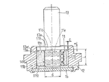
図1は、本発明にかかる動圧型焼結含油軸受ユニットの断面図である。軸受ユニットは、動圧型の焼結含油軸受11と、焼結含油軸受11を内径部に固定した円筒状のハウジング12と、焼結含油軸受11の内径部に挿入された回転軸13とを具備する。
FIG. 1 is a sectional view of a hydrodynamic sintered oil-impregnated bearing unit according to the present invention. The bearing unit includes a dynamic oil-impregnated sintered oil-impregnated
動圧型焼結含油軸受11は、回転軸13の外周面と軸受隙間を介して対向するラジアル軸受面11bを有する焼結金属からなる円筒状の軸受本体11aに、潤滑油あるいは潤滑グリースを含浸させて構成される。焼結金属からなる軸受本体11aは、銅系あるいは鉄系、またはその双方を主成分とする焼結金属で形成され、望ましくは銅を20〜95重量%使用して、密度6.4〜7.2g/cm3 に成形される。軸受本体11aの材質として、鋳鉄、合成樹脂、セラミックスなどを焼結または発泡成形し、多数の細孔を有する多孔質体としたものも用いることができる。動圧型焼結含油軸受の表面開孔率は、ラジアル軸受面11bで10%以下(望ましくは5%以下)、後述するスラスト軸受部14を構成するスラスト軸受面11f1、11f2で5%以下(望ましくは2%以下)に設定するのがよい。ラジアル軸受面11bの表面開孔率が10%以下であれば、圧力降下を防止しつつ油の循環を確保することができ、スラスト軸受面11f1、11f2の表面開孔率を5%以下とすれば、動圧溝を設けた場合でも圧力発生に伴う開孔部からの油の逃げを防止することができる。「開孔部」とは、多孔質体組織の細孔が外表面に開口した部分をいい、「表面開孔率」とは、外表面の単位面積内に占める表面開孔の面積割合をいう。
The dynamic pressure type sintered oil-impregnated
軸受本体11aの内周面11hに設けられたラジアル軸受面11bは1箇所のみに形成されており、軸受面11bには軸方向に対して傾斜した複数の動圧溝11c(へリングボーン型)が円周方向に配列形成される。動圧溝11cは、軸方向に対して傾斜して形成されていれば足り、この条件を満たす限りへリングボーン型以外の他の形状、例えばスパイラル型でもよい。焼結含油軸受11の外周には、軸受11の内径部に軸13を挿入する際の空気抜きとなる1または複数の溝11gが軸方向に沿って形成されている。なお、スピンドルモータの薄型化を図るべく、軸受内径dと軸受幅Lは、L≦1.2dを満たすように設定される。
The
上記焼結含油軸受11では、回転軸13の回転に伴う圧力発生と昇温による油の熱膨張によって軸受本体11aの内部の潤滑剤(潤滑油または潤滑グリースの基油)が軸受本体11aの表面からにじみ出し、動圧溝11cの作用によって軸受隙間に引き込まれる。軸受隙間に引き込まれた油は潤滑油膜を形成して回転軸を非接触支持する。すなわち、軸受面11bに、上記傾斜した動圧溝11cを設けると、その動圧作用によってにじみ出した軸受本体11a内部の潤滑剤が軸受隙間に引き込まれると共に、軸受面11bに潤滑剤が押し込まれ続けるので、油膜力が高まり、軸受の剛性を向上させることができる。なお、軸受ユニットの組立時において、軸受11に回転軸13を挿入する際には、軸受隙間および軸受周辺が油で満たされるよう注油しておくのが望ましい。
In the sintered oil-impregnated
軸受隙間に正圧が発生すると、軸受面11bの表面に孔があるため、潤滑剤は軸受本体の内部に還流するが、次々と新たな潤滑剤が軸受隙間に押し込まれ続けるので油膜力および剛性は高い状態で維持される。この場合、連続しかつ安定した油膜が形成されるので、高回転精度が得られ、軸振れやNRRO、ジッタ等が低減される。また、回転軸13と軸受本体11aが非接触で回転するために低騒音であり、しかも低コストである。
When a positive pressure is generated in the bearing gap, the lubricant flows back to the inside of the bearing body because there is a hole in the surface of the bearing
ラジアル軸受面11bは、一方に傾斜する動圧溝11cが配列された第1の溝領域m1と、第1の溝領域m1から軸方向に離隔し、他方に傾斜する動圧溝11cが配列された第2の溝領域m2と、2つの溝領域m1、m2の間に位置する環状の平滑部nとを備えており、2つの溝領域m1、m2の動圧溝11cは平滑部nで区画されて非連続になっている。平滑部nと動圧溝11c間の背の部分11eとは同一レベルにある。この種の非連続型の動圧溝11cは、連続型、すなわち平滑部nを省略し、動圧溝11cを両溝領域m1、m2間で互いに連続するV字状に形成した場合に比べ、平滑部nを中心として油が集められるために油膜圧力が高く、また溝のない平滑部nを有するので軸受剛性が高いという利点を有する。
The
焼結含油軸受11の軸方向一端側には、スラスト軸受部14が設けられる。図1は、焼結含油軸受11の上端側にスラスト軸受部14を設けた実施形態で、焼結含油軸受11の上軸受端面11f1(スラスト軸受面)と、回転軸13に固定した円盤状のフランジ部13aとを対向させて構成される。回転軸13とフランジ部13aは、同一部材で一体に製作したり、あるいは別体として製作してから相互に嵌合固定し、回転軸13の外周面、特に軸受11に組み込んだ際に軸受面11bと対向する外周面の直角度がフランジ部13aの軸受11側の端面13a1に対して2μm以内、望ましくは1μm以内となるように仕上げ加工される。
A
このようなスラスト軸受部14であれば、摺動接触部分が面当りとなるため、ピボット軸受で問題となる軸位置の変動を防止しつつ、単列の軸受面11bであってもモーメント剛性を高め、軸を高精度に支持することが可能となる。
In such a
ところで、上記のように回転軸13にフランジ部13aを設けた場合、回転軸13の上端には、ロータケース8やターンテーブル(5:図13参照)などの部品が固定されるため、軸受11の上端を従来のようなシールワッシャ8(図15参照)でシールすることは難しくなる。そこで、軸受11上端からの油漏れは、フランジ部13a外周面とハウジング12内周面の微小隙間による毛細管シールで行う。シール隙間cは0.05mm以下、望ましくは0.02mm以下とするのがよく、シール幅aは0.5mm以上、望ましくは1mm以上とする。シールを構成するフランジ部13a外周面やハウジング12内周面に揆油剤を塗布しておけば油漏れ防止により有効となる。
By the way, when the rotating
一方、軸受11下端側からの油漏れは、例えば底板15をハウジング12の底部開口部に圧入してからかしめることによって防止することができる。底板15とハウジング12との間の隙間を接着剤でシールしておけば、油漏れ防止にさらに有効である。
On the other hand, oil leakage from the lower end side of the
図2(A)は、底板15側からの油漏れを防止するため、樹脂、ゴムなどの弾性材料15aを底板15の上に重ねてパッキンとして使用した実施形態である。この場合も底板15は、ハウジング12に圧入した後、必要であればかしめた方が望ましい。
FIG. 2A shows an embodiment in which an
図2(B)は、フランジ部13aの外周面と対向するハウジング12の内周面に環状の凹部12aを設けた実施形態である。フランジ部13aが回転することにより、油が遠心力で凹部12aに溜まるため、ハウジング12上端からの油漏れを確実に防止することができる(遠心シール)。遠心シールのみだと、軸姿勢が横向きの場合に油漏れを生じるおそれがあるので、毛細管シールとの併用が望ましい。
FIG. 2B shows an embodiment in which an annular
図3(A)は、フランジ部13aの外周面に、回転時に軸受11側への気流が発生するような傾斜溝13a2を設けた例である。発生した気流により、油が軸受11側に押し戻されるため、軸受上端からの油漏れを防止することができる(停止中は毛細管シールで油漏れを防止する)。上記傾斜溝13a2は油漏れを防止できさえすればよいので、ラジアル軸受面11bの動圧溝11cのように高精度に加工する必要はない。溝深さは5〜30μm程度が適当で、転造などの手法で加工することができる。
FIG. 3A shows an example in which an inclined groove 13a2 is provided on the outer peripheral surface of the
この傾斜溝13a2は、図3(A)に示すようにフランジ部13aの幅(軸方向寸法)の全長にわたって形成すると、軸受11側に過剰の空気を送り込む場合があるので、図3(B)に示すように部分的に設けてもよい。この場合、ハウジング12内周面のうち、傾斜溝13a2の非形成領域との対向部に環状の凹部12aを設けておくのが望ましい。
If the inclined groove 13a2 is formed over the entire width (axial dimension) of the
図4は、軸受11の下軸受端面11f2と、軸端に設けたフランジ部13aとでスラスト軸受部14を構成した実施形態である。回転中は、回転軸13がロータ7bとステータ7a(図13参照)間の励磁力により浮上力を受けて底板15から浮いた状態となり、下軸受端面11f2(スラスト軸受面)とフランジ部13bの上面13b2とでスラスト力が支持される。底板15の上面でかつ回転軸13の直下には、潤滑性に富む樹脂材料等からなるスラストワッシャ15aが配置され、モータの起動直後や停止直前の軸端との間の摩擦低減が図られている。ハウジング12の上端開口は、油漏れ防止用のスラストワッシャ16によって閉塞され、軸との間隙を0.2mm以下とすることで外部への油の漏れ出しを防止している(毛細管作用)。シールワッシャ16の内周面や内周部の上下面、あるいはシールワッシャ16の内周面と対向する軸13の外周面に揆油剤を塗布することにより、さらに有効な油漏れ防止が図られる。
FIG. 4 shows an embodiment in which a lower bearing end face 11f2 of the
図5は、動圧型焼結含油軸受11の軸受内周面11hに軸方向に対して傾斜した油供給用の動圧溝11jを設け、この動圧溝11jで生じる動圧作用でスラスト軸受部14に油を供給するようにしたものである。動圧溝11jは、ラジアル軸受面11bの溝形成領域(スラスト軸受部14側)の動圧溝11cと連続したV字状に形成される。油供給用の動圧溝11jを設けることにより、スラスト軸受部14に油膜が形成されやすくなって潤滑性が向上し、また、スラスト軸受部14での摩耗も著しく低減されるので耐久性も飛躍的に向上する。なお、スラスト軸受部14に供給された油は、軸受端面やチャンファ部から吸収されて軸受内部に回収され、再び軸受内周面から軸受隙間に供給される。
FIG. 5 shows a dynamic pressure type sintered oil-impregnated
図6および図7は、スラスト軸受部14を、回転軸13の回転時に生じる動圧作用により回転軸13を非接触支持するようにしたものである。非接触支持であれば、スラスト軸受部14における摩擦がなくなり、耐久性が飛躍的に向上する。動圧作用は、スラスト軸受部14を構成する軸受端面11f1とこれに対向するフランジ部13aの何れか一方に、円周方向に配設された複数(3箇所以上に設けるのが望ましい)の凹部11kを有する動圧発生部17を設けることによって得ることができる。この場合、凹部11kが油溜りとなり、回転に伴って凹部内の油が隣接する凸部に引き出される際に圧力が発生し、油膜圧力が高まるのでスラスト軸受部14を安定して非接触状態に保持できる。凹部11kとしては、例えば動圧溝が考えられる。
6 and 7 show a configuration in which the
図6は、動圧発生部17を有するスラスト軸受部14の一例で、スラスト軸受面11f1に、軸受端面に描いた放射状の仮想線に対して傾斜した部分を持つ動圧溝11kを設けたものである。動圧溝11kは、へリングボーン型、すなわち半径方向のほぼ中心部に屈曲部分を有するV字状をなし、この動圧溝は、円周方向に等間隔で配列して形成される。この場合、回転に伴ってスラスト軸受部14およびその周辺の油が動圧溝11kの屈曲部分に集められて油膜圧力が高まるため、スラスト軸受部14を安定して非接触状態に保持できる。動圧溝形状としては、へリングボーン型の他にスパイラル型も適用することができる。また、動圧溝11kをフランジ部端面13a1に設け、スラスト軸受面11f1を動圧溝のない平滑面としてもよい。
FIG. 6 shows an example of a
図7は、図6と同様にスラスト軸受面11f1に動圧溝11kを設けると共に、図5と同様に軸受内周面に油供給用の動圧溝11jを設けたものである。
FIG. 7 shows a thrust bearing surface 11f1 provided with a
図8および図9は、スラスト軸受部14a、14bを軸方向に離隔した2箇所に設けて、両方向のスラスト荷重を支持できるようにしたものである。図8は軸受の両端側にフランジ部13a、13bを配し、各フランジ部13a、13bと両軸受端面11f1、11f2との間に形成された2つのスラスト軸受部14a、14bで両方向のスラスト荷重を支持できるようにしたものである。スラスト軸受部14を構成するスラスト軸受面11f1、11f2と、これに対向するフランジ部13a、13b端面との何れか一方(図面ではスラスト軸受面11f1、11f2)には、同図(b)(c)に示すように、図6と同様の動圧溝11kが形成されている。この構造であれば、両方向のスラスト支持だけでなく、回転軸13の軸受11からの抜けを防止できるので、回転軸13に衝撃荷重が加わった場合でもモータの損傷を回避することができる。特にHDD装置のように読み取り用ヘッドがディスクと僅かな隙間を介して配置されているような場合、衝撃荷重が加わってもヘッドがディスクと衝突する事態を回避することができる。
FIG. 8 and FIG. 9 show that thrust
図9は、軸受11と底板15との間にフランジ部13bを設け、フランジ部13bの両側にスラスト軸受部14a、14bを構成したものである。すなわち、フランジ部13bの上端面13a1と下側の軸受端面11f2の何れか一方、および、フランジ部13bの下端面13b2と底板15の上面の何れか一方(図面では下軸受端面11f2およびフランジ部の下端面13b2)にそれぞれ図6と同様の動圧溝11kを設けたもので、図8の構造と同様の効果が奏される。
FIG. 9 shows a configuration in which a
上記動圧型焼結含油軸受11の軸受本体11aは、上記金属粉末を圧縮成形し、さらに焼成して得られた円筒状の焼結金属素材(軸受本体素材)に対して、例えば、サイジング→回転サイジング→軸受面成形加工を施して製造することができる。
The bearing
サイジング工程は、焼結金属素材の外周面と内周面のサイジングを行って焼結工程での曲がりなどを矯正する工程で、焼結金属素材の外周面を円筒状のダイに圧入すると共に、内周面にサイジングピンを圧入して行われる。回転サイジング工程は、断面略多角形状の回転サイジングピン(断面円形のピンの外周面を部分的に平坦加工して、円周等配位置に円弧部分を残したもの)を焼結金属素材の内周面に押付けながら、サイジングピンを回転させて内周面のサイジングを行う工程である。この回転サイジングにより焼結金属素材の内周面の真円度、円筒度が矯正され、かつ表面開孔率が例えば3〜15%に仕上げられる。軸受面成形工程は、上記のようなサイジング加工を施した焼結金属素材の内周面に、完成品の軸受面に対応した形状の成形型を加圧することによって、軸受面の動圧溝の形成領域とそれ以外の領域(背11eおよび環状の平滑領域n)とを同時成形する工程である。 The sizing process is a process of sizing the outer peripheral surface and the inner peripheral surface of the sintered metal material to correct bending and the like in the sintering process, while pressing the outer peripheral surface of the sintered metal material into a cylindrical die, This is performed by pressing a sizing pin into the inner peripheral surface. The rotation sizing process is a method in which a rotation sizing pin having a substantially polygonal cross section (which is obtained by partially flattening the outer peripheral surface of a pin having a circular cross section and leaving an arc portion at a circumferentially equidistant position) is formed in a sintered metal material. This is a step of sizing the inner peripheral surface by rotating the sizing pin while pressing against the peripheral surface. By this rotation sizing, the roundness and cylindricity of the inner peripheral surface of the sintered metal material are corrected, and the surface porosity is finished to, for example, 3 to 15%. In the bearing surface forming step, a pressing die having a shape corresponding to the bearing surface of the finished product is pressed onto the inner peripheral surface of the sintered metal material subjected to the sizing processing as described above, thereby forming the dynamic pressure groove on the bearing surface. This is a step of simultaneously forming the formation region and the other region (the back 11e and the annular smooth region n).
図11は、軸受面成形工程で使用する成形装置の概略構造を例示している。この装置は焼結金属素材11’の外周面を圧入する円筒状のダイ20、焼結金属素材11’の内周面を成形する超硬合金製のコアロッド21、焼結金属素材11’の両端面を上下方向から押さえる上下のパンチ22、23を主要な要素として構成される。コアロッド21と上パンチ22は一体となっており、コアロッド21の外周面と上パンチ22のパンチ面22aの直角度は2μm以内に仕上げられている。
FIG. 11 illustrates a schematic structure of a forming apparatus used in the bearing surface forming step. This apparatus includes a cylindrical die 20 for press-fitting an outer peripheral surface of a sintered metal material 11 ', a
図10に示すように、コアロッド21の外周面には、完成品の軸受面11bの形状に対応した凹凸状の成形型21aが設けられている。成形型21aの凸部分21a1は軸受面11bにおける動圧溝11cの領域を成形し、凹部分21a2は動圧溝11c以外の領域(背11eおよび環状の平滑領域n)を成形するものである。成形型21aにおける凸部分21a1と凹部分21a2との段差は、軸受面11bにおける動圧溝11cの深さと同程度(例えば2〜5μm程度)で微小なものであるが、図面ではかなり誇張して図示されている。なお、上下軸受端面11f1、11f2に動圧溝11kを設ける場合(図6〜9参照)は、上下のパンチ22、23のパンチ面22a、23aにも当該動圧溝11kに対応した形状の転写用成形型が設けられる。
As shown in FIG. 10, an outer peripheral surface of the
この成形装置による成形は、図11に示すA〜Dの手順で行われる。 The molding by this molding apparatus is performed according to the procedures A to D shown in FIG.
先ず、焼結金属素材11’をダイ20の上面に位置合わせして配置した後、上パンチ22およびコアロッド21を降下させ、焼結金属素材11’をダイ20に圧入し、さらに下パンチ23に押付けて上下方向から加圧する(A)。
First, after positioning the sintered
焼結金属素材11’は、ダイ20と上下パンチ22・23から圧迫力を受けて変形を起こし、内周面がコアロッド21の成形型21aに加圧される。これにより、成形型21aの形状が焼結金属素材11’の内周面に転写され、軸受面11bが所定の形状および寸法に成形される(同時に焼結金属素材11’の外周面および両端面もサイジングされる)。
The
軸受面11bの成形が完了した後、焼結金属素材11’とコアロッドの位置関係を保持したまま上下のパンチ22、23およびコアロッド21を一体的に上昇させ(B)、焼結金属素材11’をダイ20から抜く。次に、クランパ24で掴んだ焼結金属素材11’の外周面に熱風発生器等の加熱機25で熱風を吹き付けて焼結金属素材11’を加熱し(C)、その後、焼結金属素材11’をコアロッド21から抜く(D)。この時、焼結金属素材11’をダイ20から抜くと同時に焼結金属素材11’にスプリングバックが生じてその内径寸法が拡大する。また、加熱によって焼結金属素材の温度がコアロッド21によりも高くなり、かつコアロッド21(超硬合金製)よりも焼結金属素材11’(銅を主成分とする)の熱膨張係数が大きいため、焼結金属素材11’の内径寸法がさらに拡大する。そのため、コアロッド21と焼結金属素材11’との干渉が回避され、動圧溝11cを崩すことなく、焼結金属素材11’の内周面からコアロッド21を抜き取ることが可能となる。スプリングバックのみでスムーズに焼結金属素材11’を抜ける場合は、加熱機25による加熱工程を省略しても構わない。
After the molding of the bearing
以上の工程を経て製造した焼結金属素材11’を洗浄し、これに潤滑油又は潤滑グリースを含浸させて油を保有させると、図1に示す動圧型滑り軸受(動圧型多孔質含油軸受)が完成する。この軸受11は、ハウジング12の内周面に例えば接着によって固定される。なお、軸受11のハウジング12への組み込み後に、含浸油とは別に注油によって軸受隙間および軸受周辺の空間を油で満たしておくと、潤滑性が著しく向上する。
When the sintered metal material 11 'manufactured through the above steps is washed and impregnated with lubricating oil or lubricating grease to retain the oil, a dynamic pressure type sliding bearing (dynamic pressure type porous oil-impregnated bearing) shown in FIG. Is completed. The
上記のようにコアロッド21の外周面と上パンチ22のパンチ面22aの直角度を2μm以内に設定しておけば、軸受内周面11hに対するスラスト軸受面11f1の直角度が3μm以内の焼結含油軸受11が提供可能となる。この軸受11と、フランジ部13aと外周面の直角度を所定範囲に設定した回転軸13とを組み合わせることにより、スラスト軸受部14での片当りを防止し、確実に面当りを実現することができる。
As described above, if the perpendicularity between the outer peripheral surface of the
11 動圧型焼結含油軸受
11a 軸受本体
11b ラジアル軸受面
11c ラジアル軸受面の動圧溝
11f1 軸受端面(スラスト軸受面)
11f2 軸受端面(スラスト軸受面)
11h 軸受内周面
11j 油供給用の動圧溝
11k スラスト軸受面の動圧溝(凹部)
12 ハウジング
13 回転軸(軸)
13a フランジ部
14 スラスト軸受部
17 動圧発生部
11 Sintered oil pressure bearing
11a Bearing body
11b Radial bearing surface
11c Dynamic pressure groove on radial bearing surface
11f1 Bearing end surface (thrust bearing surface)
11f2 Bearing end surface (thrust bearing surface)
11h Bearing inner peripheral surface
11j Dynamic pressure groove for oil supply
11k Dynamic pressure groove (recess) on thrust bearing surface
12
Claims (2)
円筒状のハウジングと、
油を含浸させた焼結金属からなり、内周面に、軸の外周面と軸受隙間を介して対向するラジアル軸受面が形成されると共に、ハウジングの端面に、動圧溝を有するスラスト軸受面がフランジ部と対向して形成され、ハウジングの内径部に固定された動圧型の焼結含油軸受とを備え、
ラジアル軸受面の表面開孔率が10%以下で、スラスト軸受面の表面開孔率が5%以下であり、
軸と焼結含油軸受との相対回転時にラジアル軸受面およびスラスト軸受面で生じる動圧作用により軸を非接触支持することを特徴とする動圧型焼結含油軸受ユニット。 A shaft having a flange portion,
A cylindrical housing;
A thrust bearing surface made of a sintered metal impregnated with oil, having a radial bearing surface formed on the inner peripheral surface facing the outer peripheral surface of the shaft via a bearing gap, and having a dynamic pressure groove on an end surface of the housing. Is formed facing the flange portion, and comprises a dynamic pressure type sintered oil-impregnated bearing fixed to the inner diameter portion of the housing,
The surface porosity of the radial bearing surface is 10% or less, the surface porosity of the thrust bearing surface is 5% or less,
A hydrodynamic sintered oil-impregnated bearing unit characterized in that the shaft is supported in a non-contact manner by a dynamic pressure action generated on a radial bearing surface and a thrust bearing surface when the shaft and the sintered oil-impregnated bearing rotate relative to each other.
Priority Applications (1)
| Application Number | Priority Date | Filing Date | Title |
|---|---|---|---|
| JP2004219142A JP2004316924A (en) | 2004-07-27 | 2004-07-27 | Dynamic pressure-type oil-impregnated sintered bearing unit |
Applications Claiming Priority (1)
| Application Number | Priority Date | Filing Date | Title |
|---|---|---|---|
| JP2004219142A JP2004316924A (en) | 2004-07-27 | 2004-07-27 | Dynamic pressure-type oil-impregnated sintered bearing unit |
Related Parent Applications (1)
| Application Number | Title | Priority Date | Filing Date |
|---|---|---|---|
| JP25711698A Division JP2000087953A (en) | 1998-09-10 | 1998-09-10 | Dynamic pressure type sintered oil-retaining bearing unit |
Publications (2)
| Publication Number | Publication Date |
|---|---|
| JP2004316924A true JP2004316924A (en) | 2004-11-11 |
| JP2004316924A5 JP2004316924A5 (en) | 2005-06-09 |
Family
ID=33475831
Family Applications (1)
| Application Number | Title | Priority Date | Filing Date |
|---|---|---|---|
| JP2004219142A Pending JP2004316924A (en) | 2004-07-27 | 2004-07-27 | Dynamic pressure-type oil-impregnated sintered bearing unit |
Country Status (1)
| Country | Link |
|---|---|
| JP (1) | JP2004316924A (en) |
Cited By (4)
| Publication number | Priority date | Publication date | Assignee | Title |
|---|---|---|---|---|
| JP2006207787A (en) * | 2004-12-28 | 2006-08-10 | Ntn Corp | Housing for dynamic pressure bearing device and manufacturing method therefor |
| KR200450524Y1 (en) | 2008-10-07 | 2010-10-08 | 엘지이노텍 주식회사 | Spindle motor |
| US8499456B2 (en) | 2005-02-10 | 2013-08-06 | Ntn Corporation | Method for producing a housing for a fluid bearing apparatus |
| US20180112712A1 (en) * | 2015-03-17 | 2018-04-26 | Ntn Corporation | Method for manufacturing sintered bearing, and sintered bearing |
-
2004
- 2004-07-27 JP JP2004219142A patent/JP2004316924A/en active Pending
Cited By (8)
| Publication number | Priority date | Publication date | Assignee | Title |
|---|---|---|---|---|
| JP2006207787A (en) * | 2004-12-28 | 2006-08-10 | Ntn Corp | Housing for dynamic pressure bearing device and manufacturing method therefor |
| US8499456B2 (en) | 2005-02-10 | 2013-08-06 | Ntn Corporation | Method for producing a housing for a fluid bearing apparatus |
| US8746978B2 (en) | 2005-02-10 | 2014-06-10 | Ntn Corporation | Fluid bearing apparatus |
| US8756816B2 (en) | 2005-02-10 | 2014-06-24 | Ntn Corporation | Method for producing a housing for a fluid bearing apparatus |
| KR200450524Y1 (en) | 2008-10-07 | 2010-10-08 | 엘지이노텍 주식회사 | Spindle motor |
| US20180112712A1 (en) * | 2015-03-17 | 2018-04-26 | Ntn Corporation | Method for manufacturing sintered bearing, and sintered bearing |
| US10697496B2 (en) * | 2015-03-17 | 2020-06-30 | Ntn Corporation | Sintered bearing |
| US11454282B2 (en) | 2015-03-17 | 2022-09-27 | Ntn Corporation | Sintered bearing |
Similar Documents
| Publication | Publication Date | Title |
|---|---|---|
| KR100619164B1 (en) | Hydrodynamic type bearing and hydrodynamic type bearing unit | |
| JP2007263228A (en) | Dynamic pressure bearing device | |
| JP2000291648A (en) | Dynamic pressure-type bearing unit | |
| JPH10306827A (en) | Dynamic pressure type oil-impregnated sintered bearing and manufacture thereof | |
| JP2000087953A (en) | Dynamic pressure type sintered oil-retaining bearing unit | |
| JP2004316924A (en) | Dynamic pressure-type oil-impregnated sintered bearing unit | |
| JP3607661B2 (en) | Hydrodynamic porous oil-impregnated bearing and method for producing the same | |
| JP2004301338A (en) | Dynamic pressure type sintering oil impregnation bearing unit | |
| JP2004316925A (en) | Dynamic pressure-type oil-impregnated sintered bearing unit | |
| JP2004360921A (en) | Dynamic pressure type sintered oil retaining bearing unit | |
| JP6877185B2 (en) | Fluid dynamic bearing device and motor equipped with it | |
| JP3607478B2 (en) | Dynamic pressure type porous oil-impregnated bearing | |
| JP2005180707A (en) | Dynamic pressure type sintered oil-impregnated bearing unit | |
| JP4451409B2 (en) | Method for producing hydrodynamic sintered oil-impregnated bearing unit | |
| WO2019139007A1 (en) | Fluid dynamic bearing device and motor equipped with same | |
| JP2004340385A (en) | Dynamic pressure type bearing unit | |
| JP2008039104A (en) | Fluid bearing device | |
| JP4188288B2 (en) | Manufacturing method of dynamic pressure type porous oil-impregnated bearing | |
| JP4327038B2 (en) | Spindle motor | |
| JP2001124059A (en) | Dynamic pressure bearing unit | |
| JP3782900B2 (en) | Hydrodynamic bearing and hydrodynamic bearing unit | |
| KR101336584B1 (en) | Fluid Dynamic Bearing | |
| JP5901979B2 (en) | Method for manufacturing fluid dynamic bearing device | |
| JP7094118B2 (en) | Sintered metal dynamic pressure bearing | |
| JP3602330B2 (en) | Dynamic pressure type sliding bearing and method of manufacturing the same |
Legal Events
| Date | Code | Title | Description |
|---|---|---|---|
| A521 | Request for written amendment filed |
Free format text: JAPANESE INTERMEDIATE CODE: A523 Effective date: 20040825 |
|
| A521 | Request for written amendment filed |
Free format text: JAPANESE INTERMEDIATE CODE: A523 Effective date: 20041108 |
|
| A621 | Written request for application examination |
Free format text: JAPANESE INTERMEDIATE CODE: A621 Effective date: 20041108 |
|
| A871 | Explanation of circumstances concerning accelerated examination |
Free format text: JAPANESE INTERMEDIATE CODE: A871 Effective date: 20041108 |
|
| A975 | Report on accelerated examination |
Free format text: JAPANESE INTERMEDIATE CODE: A971005 Effective date: 20041214 |
|
| A131 | Notification of reasons for refusal |
Free format text: JAPANESE INTERMEDIATE CODE: A131 Effective date: 20041221 |
|
| A521 | Request for written amendment filed |
Free format text: JAPANESE INTERMEDIATE CODE: A523 Effective date: 20050221 |
|
| A521 | Request for written amendment filed |
Free format text: JAPANESE INTERMEDIATE CODE: A523 Effective date: 20050303 |
|
| A02 | Decision of refusal |
Free format text: JAPANESE INTERMEDIATE CODE: A02 Effective date: 20050506 |