JP2004229730A - Slot machine - Google Patents
Slot machine Download PDFInfo
- Publication number
- JP2004229730A JP2004229730A JP2003019095A JP2003019095A JP2004229730A JP 2004229730 A JP2004229730 A JP 2004229730A JP 2003019095 A JP2003019095 A JP 2003019095A JP 2003019095 A JP2003019095 A JP 2003019095A JP 2004229730 A JP2004229730 A JP 2004229730A
- Authority
- JP
- Japan
- Prior art keywords
- variable display
- unit
- display unit
- screen
- symbol
- Prior art date
- Legal status (The legal status is an assumption and is not a legal conclusion. Google has not performed a legal analysis and makes no representation as to the accuracy of the status listed.)
- Withdrawn
Links
Images


Abstract
Description
【0001】
【発明の属する技術分野】
本発明は、スロットマシンに関し、詳しくは、複数種類の図柄を所定の順序で繰返し可変表示させる複数の可変表示部を画像表示する表示画面を備えた画像表示ユニットを含み、前記複数の可変表示部の表示結果として導出表示された図柄の組合せに応じて入賞が発生するスロットマシンに関する。
【0002】
【従来の技術】
この種の画像式のスロットマシンは、以下の特許文献1に開示されている。
【0003】
また、この種の従来のスロットマシンの中には、複数の可変表示部での図柄の可変表示を停止させるための操作部(ストップボタン)の操作順が予め定められた操作順と一致しないことには入賞を発生させることができない特殊な入賞役が規定されるととともに、その操作順を報知する“操作順ナビゲーション”機能を備えるものがあった。この種のスロットマシンは、以下の特許文献2に開示されている。
【0004】
【特許文献1】
特開平7−313660号公報
【0005】
【特許文献2】
特開2001−293136号公報
【0006】
【発明が解決しようとする課題】
しかしながら、従来のこの種のスロットマシンの“操作順ナビゲーション”では、可変表示部から離れた箇所で操作順を報知するものであり、その点、報知が解り難いという問題があった。
【0007】
本発明は係る実情に鑑み考え出されたものであり、その目的は、“操作順ナビゲーション”の報知をより遊技者にわかりやすく行なうことができるスロットマシンを提供することである。
【0008】
【課題を解決するための手段の具体例およびその効果】
(1) 複数種類の図柄を所定の順序で繰返し可変表示させる複数の可変表示部(可変表示部23L,23C,23R)を画像表示する表示画面を備えた画像表示ユニット(液晶表示ユニット2、2A、2B、または2C)を含み、前記複数の可変表示部の表示結果として導出表示された図柄の組合せに応じて入賞が発生するスロットマシン(スロットマシン1)であって、
前記複数の可変表示部の表示結果を導出表示させる操作を行なうための複数の操作部であって、各可変表示部の表示結果を個別に導出表示させるために各可変表示部に対応して設けられた操作部(ストップボタン41L,41C,41R)と、
入賞を許容するか否かを入賞役の種類別に抽選する抽選手段(S3)と、
前記複数の操作部のいずれかについての操作が検出された時点で当該操作が検出された操作部に対応する可変表示部に表示されている図柄、および当該図柄以降に表示される順番が到来する所定個数の図柄のうちに、前記抽選手段によって入賞が許容された入賞役に対応する図柄が含まれるときに、当該図柄を前記可変表示部に導出表示させる導出表示位置制御手段(S32、S45、S51の停止位置決定処理に基づいて行なわれる引込み制御)と、
前記複数の操作部の操作順が定められた特殊入賞役(押し順小役)についての入賞が前記抽選手段により許容されたときに、当該特殊入賞役に定められた操作順で前記複数の操作部が操作されたときのみ当該特殊入賞役に対応する図柄の組合せを導出表示するように制御する規制手段(S52、S53)と、
前記抽選手段により、前記特殊入賞役についての入賞が許容されたときに、当該入賞役に定められた前記複数の操作部の操作順を前記可変表示部を用いて報知(図22〜図25)する報知手段(SUB24、SUB28、SUB42)とを含む。
【0009】
上記の構成によれば、特殊入賞役についての入賞が許容されたときに、当該入賞役に定められた前記複数の操作部の操作順が、前記可変表示部が用いられて報知されるために、操作順の報知を遊技者にわかりやすく行なうことができる。
【0010】
(2) 前記報知手段は、操作順が到来した操作部に対応する可変表示部を拡大表示することによって、操作順が到来した操作部を報知する(図22、図23)。
【0011】
上記の構成によれば、操作順が到来した操作部に対応する可変表示部が目立つために、操作順の報知をより一層、遊技者にわかりやすく行なうことができる。また、遊技者が目押し操作をしやすくなる。
【0012】
(3) 前記報知手段は、操作順が到来した操作部に対応する可変表示部を拡大表示するとともに操作順が到来していない操作部に対応する可変表示部を縮小表示することによって、操作順が到来した操作部を報知する(図22)。
【0013】
上記の構成によれば、操作順が到来した操作部に対応する可変表示部が他の可変表示部との関係において目立つために、操作順の報知をより一層、遊技者にわかりやすく行なうことができる。また、遊技者が目押し操作をしやすくなる。
【0014】
(4) 前記報知手段は、操作順が到来した操作部に対応する可変表示部以外の可変表示部を遮蔽することによって、操作順が到来した操作部を報知する(図24)。
【0015】
上記の構成によれば、操作順が到来した操作部に対応する可変表示部が他の可変表示部との関係において目立つために、操作順の報知をより一層、遊技者にわかりやすく行なうことができる。
【0016】
(5) 前記報知手段は、操作順が到来した操作部に対応する可変表示部と操作順が到来していない操作部に対応する可変表示部との色彩とを異ならせることによって、操作順が到来した操作部を報知する(図25)。
【0017】
上記の構成によれば、操作順が到来した操作部に対応する可変表示部が他の可変表示部との関係において目立つために、操作順の報知をより一層、遊技者にわかりやすく行なうことができる。
【0018】
(6) 前記複数の操作部を含む前面枠ユニット(図1〜図5、図7の前面枠ユニット3)と、
前記画像表示ユニットを上部に、前記前面枠ユニットを下部にして、各々が着脱自在に取付けられる筐体(図1〜図7の筐体4)とを含み、
前記画像表示ユニットと前記前面枠ユニットとで前記筐体の前面が覆われる(図1〜図5、図7)。
【0019】
上記の構成によれば、筐体の下部が前面枠ユニットで覆われるとともに筐体の上部が画像表示ユニットによって覆われるために、大きな画像表示領域で迫力のある視覚的な演出効果に優れたゲームを提供できる。さらに、画像表示ユニットと前面枠ユニットとを各々独立して交換することができるために、メンテナンス性も向上できる。また、画像表示ユニットのみを他の機種に再利用することも可能になる。
【0020】
(7) 前記複数の操作部を備えるとともに、前記画像表示ユニットが取付けられる前面枠ユニット(図8、図9の前面枠ユニット3A)と、
該前面枠ユニットが開閉自在に取付けられる筐体(図8の筐体4)とをさらに含み、
前記前面枠ユニットは、前記画像表示ユニットの画面を臨ませる開口を形成する画面枠であって、スロットマシンの前面側の上部左隅部から右隅部に向かう方向に延びる枠(図9の上下の装飾枠3fのうち上側の装飾枠3f)を含む画面枠(図8、図9の装飾枠3f)を含み、
前記開口のサイズは、前記画像表示ユニットの画面を臨ませたときに前記開口一杯に前記画面が広がり(図9)、かつ当該画面を囲む前記画像表示ユニットのフレーム部材(フレーム部材2f)部分が隠れる大きさである(図9)。
【0021】
上記の構成によれば、スロットマシンの上部の画面枠部分を残してスロットマシンの上部ぎりぎりまでを画面の領域として確保することができるために、大きな画像表示領域で迫力のある視覚的な演出効果に優れたゲームを提供できる。また、画像表示ユニットのフレーム部材部分は開口の裏手に隠されるために、スロットマシンの正面から見たときに、画像表示ユニットのフレーム部材が露出することによって意匠性が損なわれることもない。
【0022】
【発明の実施の形態】
以下に本発明の実施の形態を図面に基づいて詳細に説明する。
【0023】
[スロットマシンの構造説明]
図1は、スロットマシン1の全体正面図である。また、図2は、スロットマシン1の右斜め上方から見た斜視図であり、図3は、スロットマシン1の側面図である。
【0024】
スロットマシン1は、液晶表示ユニット2と、各種操作ボタン43〜46、41L,41C,41R等が設けられた前面枠ユニット3と、それら両ユニットが収容される筐体4とから構成されている。
【0025】
液晶表示ユニット2は、スロットマシン1の略上部の左右両隅部にまで至る大きなサイズの画面21(図1参照)を有する。画面21には、ゲームの主要部を構成する複数の可変表示部23L,23C,23Rが表示される他、遊技状況に応じた様々な画像が表示される。液晶表示ユニット2の正面には、画面21を保護するガラス板19(図2参照)が組み込まれている。
【0026】
図1に示されるように、本実施の形態に関わるスロットマシンは、その前面側の半分よりも上部のほぼ全域を表示領域としているため、視覚的な演出効果を高めることができる。
【0027】
図1に示される表示画面のレイアウトは、電源を投入したときに表示されるノーマル画面(客待ち画面)のレイアウトである。ノーマル画面では、キャラクタなど演出効果を高めるための動画像が表示される演出表示部22、左可変表示部23L,中可変表示部23C,右可変表示部23R、その他、複数種類の表示部24〜32が図示されるレイアウトによって表示される。
【0028】
前面枠ユニット3には、前方にテーブル状に張り出した操作面34が形成されている。操作面34には、メダル投入口が形成されたメダル投入部51と、精算ボタン45と、1枚BETボタン43と、MAXBETボタン44とが設けられている。また、操作面34の下方に位置する操作パネル35には、スタートレバー42と、左ストップボタン41L,中ストップボタン41C,右ストップボタン41Rと、メダル詰まり解除ボタン46とが設けられている。
【0029】
操作パネル35の下方両サイドには、遊技効果LED24(図11参照)が内蔵された遊技効果ランプ部36a,36bが組み込まれている。ランプ部36bには、液晶表示ユニット2および前面枠ユニット3を施錠する施錠装置49(図3参照)の鍵穴53が形成されている。さらに、前面枠ユニット3の中段位置にはスピーカ5が組み込まれ、下段位置にはメダル払出穴54から排出されるメダルを受けるメダル受け部55が形成されている。
【0030】
図3を参照して、液晶表示ユニット2は、筐体4に取付けられた状態で、下方の前面枠ユニット3とともに施錠装置49によって施錠される。筐体4内部には、ゲームを制御する遊技制御手段(ゲーム制御手段)の一例となる遊技制御基板100、表示制御手段の一例となる表示制御基板200、ホッパー60、余剰メダル貯留タンク61等が取付けられている。
【0031】
液晶表示ユニット2には、上下左右をフレーム部材20w(図3では上下位置のみ図示)に囲まれる画面21と、ドライバ基板20dとから構成される液晶表示装置20が組込まれている。前面枠ユニット2は、画面21を臨ませる開口を形成する装飾枠2wを有しており、透明のガラス板19を介して、スロットマシン1の正面から画面21の映像を視認できる。装飾枠2wには、スロットマシンの機種のデザインコンセプト(動物キャラクタもの、人気アニメものなど)にマッチした様々な装飾が施されている。
【0032】
特に、本実施の形態のスロットマシンでは、液晶表示ユニット2内に収納された液晶表示装置20(画面21、ドライバ基板20dから成る)によって可変表示装置が構成されているために、ドラムによって可変表示装置を構成する従来のスロットマシンに比較して、奥行き幅をスリムにすることができる。
【0033】
図3の一点破線に示されるように、スロットマシン1の正面から見たときに、画面21を囲むフレーム部材20w部分が装飾枠2wによって隠される。換言すれば、画面21を臨ませる開口は、スロットマシン1の正面から画面21を視認したときに、画面21を囲むフレーム部材20w部分が隠れる大きさである。このためフレーム部材20wが正面から剥き出しになって、装飾枠2wの装飾効果を減じることがない。また、同じ構造でデザインコンセプトが異なる他の機種から液晶表示装置20を流用する場合にも、液晶表示装置20のフレーム部材20wの意匠の相違が問題にならない。
【0034】
図4は、スロットマシン1の内部構造を説明するための図である。また、図5は、液晶表示ユニット2および前面枠ユニット3の筐体4への取付け構造を説明するための図である。
【0035】
液晶表示ユニット2および前面枠ユニット3は、各々、上下一対の蝶番2dによって、筐体4に対して開閉自在にビス止め(ビス2g)されている。特に、液晶表示ユニット2は、衝撃を緩衝するためのゴムパッキン2eを介して、筐体4に取付けられる。
【0036】
このように、液晶表示ユニット2および前面枠ユニット3が筐体4に対して開閉自在に取付けられるために、スロットマシン内部の点検作業等のメンテナンス性が向上する。
【0037】
筐体4の内部には、電源ユニット303、ホッパー60、余剰メダル貯留タンク61、遊技制御基板100、および表示制御基板200が設けられている。遊技制御基板100と表示制御基板200とは、コネクタケーブル63によって、接続されている。また、表示制御基板200と液晶表示ユニット2内の図示されない液晶表示装置20とは、コネクタケーブル62によって接続されている。
【0038】
液晶表示ユニット2は、液晶表示装置20(図4では図示省略)が取付けられた“ロの字”状の取付け枠2bと、取付け枠2bを固定するための6つの取付けリブ2cが裏面側(スロットマシン1の内側)に形成された金属性または樹脂性の液晶表示ユニット本体2aとから成る。
【0039】
[取付け構造の変形例1]
図6は、取付け構造の変形例1を示す図である。この変形例1では、L型ピン2jによって、液晶表示ユニット2Aが筐体4に対して開閉自在に取付けられる。その他の点では、図5に示される構造と同一である。また、スロットマシンの構成についても、図1〜図4がそのまま適用される。
【0040】
図6に示されるように、液晶表示ユニット2Aの上側部には、L型ピン2jが上下方向にスライド可能に設けられているとともに、L型ピン2jの破線に示す部分を矢印方向に回動させた上で差入れることが可能となるピン固定部2hが設けられている。一方、筐体4には、L型ピン2jの先端を挿入可能な挿入孔が形成されたL型ピン受け部4aが設けられている。
【0041】
さらに、液晶表示ユニット2Aの下側部には、挿入孔が形成されたユニット保持部材2kがビス止めされている。一方、筐体4には、その挿入孔に挿入される突起が形成されたユニット保持部材4bがビス止めされている。
【0042】
液晶表示ユニット2Aの取付け方法は、以下の通りである。まず、L型ピン2jを破線に示す状態としてL型ピン2jを引き抜く。次に、液晶表示ユニット2A側のユニット保持部材2kが筐体4側のユニット保持部材4bの上に重なるようにして液晶表示ユニット2Aを筐体4側に案内し、ユニット保持部材4bの突起をユニット保持部材2kの挿入孔に挿入する。次に、L型ピン2jを挿通して、筐体4側のL型ピン受け部4aに形成された挿入孔にL型ピン2jの先端を差入れる。最後に、L型ピン2jが抜け落ちないように、L型ピン2jを図6の矢印方向に回動させて、ピン固定部2hに差入れる。
【0043】
以上により、液晶表示ユニット2Aは、筐体4に対して、開閉自在、かつ着脱自在に取付けられる。この取付け構造の変形例1によれば、L型ピン2jの抜き差しによって、簡単に液晶表示ユニット2Aを筐体4から取り外すことができ、より、メンテナンス性を向上させることができる。なお、前面枠ユニット3についても、同様にして、L型ピン2jによって筐体4に開閉自在、かつ着脱自在に取付けるようにしてもよい。あるいは、前面枠ユニット3については、図4、5に示されるように、蝶番2dによって筐体4に開閉自在に取付けるようにしてもよい。
【0044】
[取付け構造の変形例2]
図7は、取付け構造の変形例2を示す図である。この変形例2では、液晶表示ユニット2Bの裏面側に設けられた直方体状の取付け部材2nが筐体4側のガイドレール4cに嵌まり込むことによって、液晶表示ユニット2Bが筐体4に対して着脱自在に取付けられる。その他の点では、図5に示される構造と同一である。また、スロットマシンの構成についても、図1〜図4がそのまま適用される。
【0045】
図7に示されるように、液晶表示ユニット2Bの裏面側四隅の各々には、取付け部材2nが植立している。一方、筐体4側には、各々の取付け部材2nに対応する位置に、取付け部材2nが嵌まり込むガイドレール4cが取付けられている。
【0046】
各々の取付け部材2nとガイドレール4cとを位置合わせして、液晶表示ユニット2を筐体4に押し込むことにより、液晶表示ユニット2Bが筐体4に取付けられる。
【0047】
この取付け構造によれば、筐体4の前面側から液晶表示ユニット2Bを挿入してワンタッチで液晶表示ユニット2Bを筐体4に取付けることができるために、作業性の向上を図ることができ、たとえば、液晶表示ユニット2Bの交換、メンテナンスを容易に行なうことができる。
【0048】
なお、図において、液晶表示ユニット2B側の2p、および筐体4側の4pは、双方が接続される、一方がオス、他方がメスのコネクタである。液晶表示ユニット2側のコネクタ2pと、筐体4側のコネクタ4pとが接続されることによって、液晶表示ユニット2B側の液晶表示装置20(図3参照)と、筐体4側の表示制御基板200とが通信可能になる。したがって、このようなコネクタを設けた場合には、図示されるコネクタケーブル62は不用である。この変形例2においては、コネクタケーブル62、またはコネクタ2p,4pのいずれを採用して、表示制御基板200と液晶表示装置20との通信経路を確保するようにしてもよい。
【0049】
[取付け構造の変形例3]
図8は、取付け構造の変形例3を示す図である。この変形例3では、図4に示される前面枠ユニット3とは異なり、前面枠ユニット3Aが大型でスロットマシン前面すべてを覆う。そして、液晶表示ユニット2Cは、前面枠ユニット3Aの上部に形成された開口部分に、前面枠ユニット3Aの裏面側から取付けられる。ただし、スロットマシンの前面側の構成については、図1がそのまま適用される。
【0050】
図8に示されるように、前面枠ユニット3Aは、蝶番2dによって、筐体4に対して開閉自在に取付けられる。液晶表示ユニット2Cには、前面枠ユニット3Aへの取付けに用いられる耳部2r,2qが形成されている。一方、前面枠ユニット3Aの開口上部には液晶表示ユニット2Cの耳部2rが挿入される溝3aが形成されているとともに、開口の底部には液晶表示ユニット2Cの耳部2qに対応する受け部3bが形成されている。なお、溝3aの上方に形成された隆起は、溝3aから上方に露出する耳部2rをスロットマシン1の正面側から見えないようにするためのものである。
【0051】
液晶表示ユニット2の取付け方法は、以下の通りである。まず、液晶表示ユニット2Cの上部側を多少前面枠ユニット3側に傾け、耳部2rを筐体4側の溝3aに挿入する。次に、液晶表示ユニット2C側の耳部2qを、前面枠ユニット3A側の受け部3bにあてがい、ビス穴を位置合わせした上で、耳部2qと受け部3bとをビス止めする。これにより、液晶表示ユニット2Cは、前面枠ユニット3A側の装飾枠3fによって囲まれる開口に対して取付けられる。このとき、前面枠ユニット3A側の開口一杯に、液晶表示ユニット2Cの画面21が広がる。
【0052】
図9に、液晶表示ユニット2Cの画面21および当該画面21を囲む液晶表示ユニット2Cのフレーム部材2fと、前面枠ユニット3Aに形成された装飾枠3fにより囲まれる開口のサイズとの関係を示した。
【0053】
図9において、左側は液晶表示ユニット2Cの正面図であり、右側は当該液晶表示ユニット2Cが組み付けられた前面枠ユニット3Aの一部を示す側面図である。一点破線は、側面図によって示された前面枠ユニット3A内の液晶表示ユニット2Cと、正面図によって示された液晶表示ユニット2Cとの上下方向の対応関係を示している。
【0054】
図9に示されるように、画面21を臨ませる開口のサイズは、液晶表示ユニット2Cの画面21を臨ませたときに開口の上下方向一杯に画面21が広がり、かつ当該画面21を囲む液晶表示ユニット2Cのフレーム部材2f部分が前面枠ユニット3Aに形成された装飾枠3fにより隠れる大きさである。
【0055】
したがって、スロットマシン1の正面から見たときに、画面21を囲むフレーム部材2f部分が装飾枠3fによって覆われる。このためフレーム部材2fが正面から剥き出しになって、装飾枠3fの装飾効果を減じることがない。また、同じ構造でデザインコンセプトが異なる他の機種から液晶表示ユニット2Cを流用する場合にも、液晶表示ユニット2Cのフレーム部材2fの意匠の相違が問題にならない。
【0056】
[カードユニットの接続例]
図10は、図1に示されるスロットマシン1に、プリペイドカードを処理するカードユニット50を接続したときのスロットマシンの内部構造を示す図である。この接続例では、ゲームを開始する際に、プリペイドカードの残額が賭数を設定するためのクレジットに変換される一方、ゲームを終了する際に、残存するクレジットがプリペイドカードの残額に加算される。
【0057】
したがって、遊技媒体の一例となるメダルはゲームに用いられない。図示のように、筐体4内には、図4に示されるようなホッパー60や余剰メダル貯留タンク61等は設けられていない。また、液晶表示ユニットや前面枠ユニットの取付け構造は、図4〜図8のいずれのものをも採用可能であるが、いずれを採用したときでも、ホッパー60からメダルをスロットマシン前面側に案内して排出する機構部分は、不要である。さらに、スロットマシンの正面構成は、メダル受け部55が存在しない点、およびメダル投入部51に代えて“プリペイドカードのカード残額を引き落とすための引き落としボタン”が設けられる点を除いては、図1に示すものと同一である。
【0058】
図10を参照して、筐体4内には、図4に示されるものと同様に、電源ユニット303、遊技制御基板100、表示制御基板200が設けられている。さらに、筐体4内には、コネクタケーブル(図示省略)を介してカードユニット50と接続されるカードユニット制御基板500が設けられている。カードユニット制御基板500は、カードユニット50内の制御用マイクロコンピュータと通信し、協同して、カード残額の更新処理、スロットマシン側のクレジットの更新処理を行なう。
【0059】
[表示部の説明]
次に、図1、および図2〜10を参照して説明したスロットマシンの画面に表示される各種の表示部について、図1を参照して詳細に説明する。
【0060】
可変表示部23L,23C,23Rは、各々で複数種類の図柄を上から下にスクロール表示(可変表示、変動表示ともいう)させる表示部である。可変表示部23L,23C,23Rの表示位置および表示サイズは、ゲーム状況に応じて変化する。
【0061】
賭け表示部24は、遊技者がゲームに賭けた賭数を表示する。各賭け表示部24は、上段、中段、下段の3本と斜め2本の計5つの入賞ラインのいずれかと対応しており、賭数に応じた有効な入賞ラインを識別可能に報知する有効ライン表示部としても機能する。
【0062】
演出表示部22は、入賞役の当選告知などの演出画像を表示する。演出表示部22の表示内容、および表示サイズは、ゲーム状況に応じて変化する。
【0063】
WIN表示部25は、入賞が発生したときに点灯表示する。リプレイ表示部26は、リプレイ入賞が発生した場合に点灯表示する。スタート表示部28は、賭数が設定されることによりスタート操作をすることが可能な状態となった場合に点灯表示し、有効なスタート操作が検出されることにより消灯表示する。投入指示表示部29は、メダルを受付可能な状態である場合に点滅し、最大の賭数が設定され、かつ、クレジット数が上限数に至った場合、ゲームが開始された場合等に消灯表示する。
【0064】
ウエイト表示部27は、ウエイトタイム中にスタート操作が検出された場合に点灯表示し、ウエイトタイムが経過した後に消灯表示する。ウエイトタイムは、ゲームがあまりに早く進行し過ぎてしまうことを規制するためにスロットマシンに設定された、ゲーム進行規制期間である。このウエイトタイム中にスタート操作が検出されると、ウエイトタイムが経過した後に、可変表示部が始動するように設計されている。したがって、十分な時間間隔を空けて複数のゲームを順次行なっている場合にはスタートレバー42の操作時にゲームの進行が規制されることはないが、遊技者が複数のゲームを短時間で消化しているような場合にはウエイトタイムによってゲームの進行が規制され、ウエイトタイムが経過するまでの間、可変表示部23L,23C,23Rの始動待ち状態となる。
【0065】
スロットマシン1では、前回のゲームで可変表示部の変動が開始した時点を基準として、たとえば、4.1秒のゲーム進行規制期間が設定されており、前回のゲームで可変表示部23L,23C,23Rの変動が開始した時点から4.1秒が経過する前にスタート操作が検出された場合、ゲーム進行規制期間が経過した後に可変表示部23L,23C,23Rが始動する。
【0066】
クレジット表示部30は、クレジット数を表示する。なおクレジットは、遊技者所有の有価価値としてスロットマシン1に記憶されているメダル数である。このクレジットは、スロットマシン1へのメダルの投入、および払出しのある入賞の発生によって加算更新され、賭数を設定したり、精算操作に基づいてメダルを払出したりすることによって減算更新される。スロットマシン1は、最大、メダル50枚分の価値をクレジットとして記憶可能である。クレジット数が上限数(=50)に達した場合には、投入指示表示部29が消灯表示する。そして、記憶の上限を超えるクレジットの加算更新の要求が発生した場合には、その上限を超えるメダルがメダル払出穴54から払出される。
【0067】
ゲーム回数表示部31は、ビッグボーナス中のボーナス入賞状況や、レギュラーボーナス中の入賞回数等を表示する。また、ビッグボーナスが終了して打止状態となった際には、ゲーム回数表示部31は、「END」という文字を表示して、遊技者に打止状態である旨を報知する。ペイアウト表示部32は、1ゲーム中に発生した入賞に基づいて遊技者に付与されるクレジット数を1ゲーム毎に表示する。
【0068】
[操作部の説明]
次に、図1を参照して、前面枠ユニット3に設けられた各種の操作部について説明する。
【0069】
1枚BETボタン43は、1クレジットを賭ける際に押圧するボタンである。MAXBETボタン44は、1ゲームにおいて許容される賭数の最大数(たとえばメダル3枚分)をクレジットに記憶されている範囲内でゲームに賭ける際に押圧するボタンである。
【0070】
精算ボタン45は、スロットマシン1に記憶されているクレジットに基づいて、メダル払出穴54からメダルの払出しを受ける際に押圧するボタンである。この精算ボタン45を押圧することに伴って、クレジット表示部30に表示されているクレジット数が0になるまで減算更新されるとともに、クレジット相当数のメダルが払出される。
【0071】
スタートレバー42は、ゲームを開始する際に操作するレバーである。賭数を設定した後、このスタートレバー42を操作することにより各可変表示部23L,23C,23Rが一斉に変動し始める。
【0072】
各ストップボタン41L,41C,41Rは、ゲームが開始した後、変動している可変表示部を停止させる際に操作するボタンである。メダル詰まり解除ボタン46は、メダル投入口52に投入したメダルがスロットマシン1の内部で詰まった場合、メダル詰まりを解消させる際に操作するボタンである。
【0073】
[ゲームの説明]
次に、スロットマシン1により提供されるゲームの概要について説明する。
【0074】
ゲームを開始するためには、最初に賭数を設定する。賭数は、1枚BETボタン43またはMAXBETボタン44を押圧することにより、1〜3のいずれかに設定できる。ただし、クレジット表示部30に表示されるクレジット数が3に満たない場合、設定可能な賭数の範囲は、そのクレジット数の範囲内に限られる。また、レギュラーボーナスゲームを行なう場合には、賭数が1に限定される。なお、前回のゲーム結果がリプレイ入賞(再ゲーム入賞)であった場合には、前回の賭数が自動的に設定されるために、賭数の設定操作は不要である。
【0075】
1枚BETボタン43を1回押圧すると、賭数が1に設定され、続けて1枚BETボタン43を1回押圧すると、賭数が2に設定され、さらに、1枚BETボタン43を1回押圧すると、賭数が3に設定される。一方、MAXBETボタン44を1回押圧すると、賭数が最大数の3に設定される。
【0076】
また、直接、メダルをメダル投入部51に投入することによって賭数を設定することも可能であり、メダルを1枚投入する毎に、所定の上限数の範囲内で賭数が1ずつ加算される。なお、賭数の上限数を超えてメダルが投入された場合、クレジット数が上限値に達するまではクレジットが加算更新され、クレジット数が上限値に達した時点でメダルがメダル払出穴54から返却される。
【0077】
なお、図10に示したカード式スロットマシンでゲームをする場合には、最初に、メダル投入部51に代えて設けられる“引き落としボタン”を押圧して、カード残額の引き落しと引換えに、クレジットを得る。このクレジットは、クレジット表示部30に加算表示される。その後、1枚BETボタン43、あるいはMAXBETボタン44を操作して賭数を設定する。
【0078】
スロットマシン1において、賭数が設定された場合にはスタート表示部28が点灯表示する。これにより、スタートレバー42の操作が有効に受付けられる状態になった旨が遊技者に報知される。スタート表示部28が点灯表示している際にスタートレバー42を操作すれば、各可変表示部23L,23C,23Rが一斉に変動(スクロール)し始める。ただし、スタートレバー42を操作した時点がウエイトタイム期間内にあれば、可変表示部がスクロールすることなく、ウエイト表示部27が点灯表示する。その後、ウエイトタイム期間が経過してウエイト表示部27が消灯表示するのと同時に可変表示部で複数種類の図柄が一斉に変動(スクロール)し始める。なお、スタートレバー42を操作したタイミングで表示画面が、所定のビッグボーナス告知画面に切換わり、 “ビッグボーナスのフラグが立っていること”が遊技者に報知されることがある。
【0079】
可変表示部における図柄の変動速度が一定速度に達した後、各ストップボタン41L,41C,41Rの操作が有効化される。ストップボタン41Lは可変表示部23Lに、ストップボタン41Cは可変表示部23Cに、ストップボタン41Rは、可変表示部23Rに、各々、対応して設けられている。遊技者は自らの操作によって可変表示部23L,23C,23Rを停止させる順序を決定できる。
【0080】
以下の説明では、変動を開始した可変表示部23L,23C,23Rのうち、“1つ目の可変表示部の図柄の変動を停止させる操作”、“2つ目の可変表示部の図柄の変動を停止させる操作”、“3つ目の可変表示部の図柄の変動を停止させる操作”を、各々、“第1停止操作”、“第2停止操作”、“第3停止操作”という。なお、このスロットマシン1では、設計上、左ストップボタン41L、中ストップボタン41C、右ストップボタン41Rの順で停止操作する手順が、標準的な押し順とされている。この標準的な押し順を“順押し”という。
【0081】
遊技者がストップボタン41L,41C,41Rのうち、いずれかを押圧操作すれば、操作されたストップボタンに対応する可変表示部の図柄の変動が停止する。
【0082】
一方、遊技者がストップボタン41L,41C,41Rを操作しない場合には、各可変表示部23L,23C,23Rで図柄が一斉に変動開始してから所定の“操作待ち時間”が経過した後に各可変表示部23L,23C,23Rでの図柄の変動が、たとえば23L,23C,23Rの優先順序で自動的に順次停止する。
【0083】
すべての可変表示部23L,23C,23Rに図柄が停止した時点で、各可変表示部23L,23C,23Rの上段、中段、下段の3段の図柄のうち、賭数に応じて定められる有効な入賞ライン上に位置する図柄の組合わせによって入賞の有無が決定される。賭数が1の場合には、可変表示部における中段の横1列の入賞ラインのみが有効ラインとなる。賭数が2の場合には、可変表示部における上段、中段、下段の横3列の入賞ラインが有効ラインとなる。賭数が3の場合には、可変表示部における横3列と斜め対角線上2列の合計5本の入賞ラインが有効ラインとなる。
【0084】
有効ライン上における図柄の組合わせが予め定められた特定の表示態様となって入賞が発生した場合には、遊技効果ランプ部36a,36bが所定の態様で点滅するとともにスピーカ5から効果音が出力される。その後、入賞に応じた数のクレジットが付与され、クレジット表示部30のクレジット数が更新される。また、ペイアウト表示部32には、その払出数が表示される。なお、クレジット数が上限(=50)に達した場合には、直接、メダルがメダル払出穴54から払出される。
【0085】
また、可変表示部23L,23C,23Rの表示結果が、特に予め定められた特別の表示態様(たとえば、777)となった場合には、ビッグボーナス入賞となり、クレジットが付与されるとともに、ビッグボーナスゲームを行なうことが可能な遊技状態となる。ビッグボーナスゲームが提供される遊技状態をビッグボーナス状態(あるいは単にビッグボーナス)ともいう。ビッグボーナス状態では、後述するようにレギュラーボーナスという特別な入賞役を発生させることも可能となる。
【0086】
たとえば、ビッグボーナス入賞が発生すると、ゲーム回数表示部31にはビッグボーナスゲームを行なうことができる回数(たとえば、最大30回)が表示され、ビッグボーナスゲームが消化される毎に、ゲーム回数表示部31に表示されているゲーム数が1ずつカウントダウンされて表示される。同様に、レギュラーボーナス入賞が発生すると、ゲーム回数表示部31にはレギュラーボーナスゲームを行なうことができる回数(たとえば最大12回)が表示される。そして、レギュラーボーナスゲームが消化される毎に、ゲーム回数表示部31に表示されているゲーム数が1ずつカウントダウンされて表示される。レギュラーボーナスゲームが提供される遊技状態をレギュラーボーナス状態(あるいは単にレギュラーボーナス)ともいう。
【0087】
なお、レギュラーボーナス状態では、通常、レギュラーボーナスゲームを行なうことができる最大継続ゲーム回数(たとえば12回)に達する前に、入賞ゲーム数が、レギュラーボーナス状態の終了条件である規定回数(たとえば、8回)に達するケースがほとんどである。このため、レギュラーボーナス入賞が発生した場合、ゲーム回数表示部31にはレギュラーボーナスゲームを行なうことができる最大継続ゲーム回数(たとえば12回)ではなく、入賞を発生させることのできる規定ゲーム数(たとえば、8回)を表示し、レギュラーボーナスゲームで入賞が発生する毎に、その規定ゲーム数からカウントダウン表示するようにしてもよい。
【0088】
[制御回路の説明]
図11は、スロットマシン1に設けられた遊技制御基板および表示制御基板の構成を説明するためのブロック図である。
【0089】
スロットマシン1に設けられた基板のうち、遊技制御基板100によって遊技の進行が制御され、表示制御基板200によって遊技の進行に応じた様々な表示制御が実行される。遊技制御基板100および表示制御基板200は、電源基板300から電源の供給を受けて動作する。電源基板300には、電源をオフ・オンするためのメインスイッチ302と、入賞役の当選率を設定するための設定スイッチ301とが接続されている。
【0090】
遊技制御基板100は、表示制御基板200と配線接続されている。遊技制御基板100には、制御部としての遊技制御用マイクロコンピュータ101が搭載されている。遊技制御用マイクロコンピュータ101から表示制御基板200へは、指令情報の一例となる各種のコマンドが出力される。遊技制御基板100には、遊技制御基板100の内部から表示制御基板200への信号の出力を許容するが遊技制御基板100の外部から内部へ信号が入力されることを阻止する不可逆性出力手段として機能するバッファ回路(図示省略)が設けられている。このため、遊技制御基板100と表示制御基板200との間において、遊技制御基板100から表示制御基板200への一方向通信が担保され、コマンドの伝送経路を介して遊技制御基板100に信号を入力させて不正な制御動作を行なわせる不正行為を防止できる。
【0091】
遊技制御基板100に配線接続されたスイッチのうち、1枚BETスイッチ430は、1枚BETボタン43の操作を検出するスイッチであり、MAXBETスイッチ440は、MAXBETボタン44の操作を検出するスイッチである。
【0092】
スタートスイッチ420は、スタートレバー42の操作を検出するスイッチであり、左、中、右ストップスイッチ411L,411C,411Rは、左、中、右ストップボタン41L,41C,41Rの操作を検出するスイッチである。
【0093】
精算スイッチ450は、精算ボタン45の操作を検出するスイッチであり、投入メダルセンサ510は、メダル投入部51に投入されたメダルを検出するセンサである。流路切替ソレノイド511は、メダル投入部51に投入されたメダルの流路をホッパー60側とメダル払出穴54側とに切換えるためのソレノイドである。
【0094】
表示制御基板200には、可変表示部23L,23C,23R等を表示する液晶表示装置20と、スピーカ5と、遊技効果LED24とが接続されている。表示制御基板200には、表示制御用マイクロコンピュータ201、その他の各種回路が搭載されている。図12にその構成を示す。
【0095】
図12を参照して、表示制御基板200は、表示制御用マイクロコンピュータ201と、I/Oポート213,214と、サウンドジェネレータ211と、アンプ212と、LED駆動回路215と、VDP(Video Display Processor)205と、リセット回路209と、発振回路208と、VRAM(Video RAM)207と、キャラクタROM206と、LCD(Liquid Crystal Display)駆動回路210とを含む。
【0096】
また、表示制御用マイクロコンピュータ201は、制御動作を所定の手順で実行することのできるCPU(Central Processing Unit)202と、CPU202の制御プログラムを格納するROM(Read Only Memory)203と、必要なデータの書込みおよび読出しができるRAM(Random Access Memory)204とを含む。
【0097】
I/Oポート213は、遊技制御基板100から送られてきたコマンドを受信して、表示制御用マイクロコンピュータ201のCPU202に渡す。CPU202は、これらのコマンドに従って、表示制御用プログラムを実行し、指示信号をI/Oポート214に出力する。I/Oポート214は、CPU202が出力した指示信号を、VDP205、サウンドジェネレータ211、またはLED駆動回路215に渡す。
【0098】
VDP205は、リセット回路209からのリセット信号に従ってリセットされると共に、発振回路208からのクロック信号に従って動作する。VDP205は、CPU202からの指示信号に基づいて、キャラクタROM206を参照し、画像データを生成する。VDP205が生成した画像データは、VRAM207に展開された後、VDP205により読み出されてLCD駆動回路210に渡される。LCD駆動回路210は、VDP205から受け取った画像データに基づいて液晶表示装置20を駆動し、液晶表示装置20の表示画面21(図1参照)に所望の画像を表示させる。
【0099】
サウンドジェネレータ211は、CPU202からの指示信号に基づいて音声信号を生成し、アンプ212に供給する。アンプ212は、この音声信号を増幅し、スピーカ5に出力する。LED駆動回路215は、CPU202からの指示信号に基づいて、複数個設けられた遊技効果LED24を制御する。
【0100】
[引込み制御の説明]
次に、図柄を停止させる“引込み制御”について、説明する。図11に示されるように、スタートスイッチ420の検出信号は、遊技制御用マイクロコンピュータ101に入力される。遊技制御用マイクロコンピュータ101は、スタートスイッチ420の検出信号を受け、1個の乱数(当選判定用乱数という)をサンプリングし、そのサンプリングされた乱数と、遊技制御用マイクロコンピュータ101内に格納されている入賞役別の入賞判定テーブルとを参照して、入賞の発生を許容するか否かを入賞役別に決定し、その決定結果を一時記憶する。これにより、スタート操作がされたタイミングで、入賞役の当選の有無が各入賞役の種類別に決定される。以下、入賞の発生が許容されていることを、“内部当選している”という。いずれかの入賞役が内部当選した場合、その入賞役に対応する当選フラグがスロットマシン1の内部で設定される。
【0101】
このスロットマシンでは、1ゲーム毎に入賞役別に当選の有無の抽選がなされるが、抽選に用いられる当選判定用乱数は、遊技制御基板100の遊技制御用マイクロコンピュータ101により実行される制御プログラムで生成されるソフト乱数であってもよく、遊技制御用マイクロコンピュータ101の外部に設けた乱数発生回路から供給されるハード乱数であってもよい。
【0102】
遊技制御用マイクロコンピュータ101は、左、中、右ストップスイッチ411L,411C,411Rによって、各可変表示部23L,23C,23Rの図柄の変動を停止させるストップ操作が検出された時点で、ストップ操作に対応する可変表示部に表示されている図柄を判断する。
【0103】
判断の対象となる図柄は、たとえば、この実施の形態に関わるスロットマシン1の場合には、可変表示部の上段、中段、下段位置の図柄のうちの、上段位置の図柄である。遊技制御用マイクロコンピュータ101は、基準位置の図柄、または、それに後続して可変表示される4図柄のうちのいずれかを基準位置(上段位置)に停止させる。つまり、ストップ操作が検出された時点で即座に可変表示部での図柄の変動を停止させるか、あるいは、その時点から4図柄が変動するまでの間に、可変表示部での図柄の変動を停止させる。
【0104】
基準位置の図柄を含む5図柄のうちのいずれを停止させるかを判断するにあたり、内部当選状況が参照される。たとえば、その5図柄のうちに、内部当選している入賞役に対応する図柄が含まれる場合には、優先的にその図柄が有効ライン上に揃うように、基準位置に停止させる図柄が選択される。また、たとえば、すでに変動が終了している2つの可変表示部の有効な入賞ラインに、内部当選していない入賞役の図柄の組合せが揃ってリーチが成立しているときには、たとえ、ストップ操作が検出された時点でそのストップ操作に対応する可変表示部に表示されている図柄がそのリーチライン上に位置する場合でも、その図柄以外がリーチライン上に停止するように、基準位置に停止させる図柄が選択される。
【0105】
このように、ストップ操作が検出された時点における可変表示部の図柄の状況と、内部当選状況とを判断して、内部当選している入賞役に対応する図柄を引込む制御、および、内部当選していない入賞役についての入賞が発生しないようにその入賞役に対応する図柄以外を引込む制御を、“引込み制御”という。なお、上記した基準位置は、可変表示部の上段に限られるものではなく、中段、下段に設定してもよい。
【0106】
遊技者は、入賞を発生させるべく、所望の図柄が所望の入賞ラインに停止するように、タイミングを見計らって、図柄の変動を停止させる操作をする。このような操作を、特に、“目押し操作”という。たとえば、当選フラグが設定されたゲームでは、その当選フラグに対応する入賞役の図柄を引込むように可変表示部が引込み制御されるために、“目押し操作”により、その当選フラグに対応する役の入賞を発生させることが可能である。しかしながら、当選フラグが設定されていないゲームでは、入賞となる図柄以外を引込むように可変表示部が制御されるために、目押し操作をしても入賞を発生させることはできない。
【0107】
また、当選フラグが設定されたゲームであっても、“目押し操作”のタイミングが悪ければ、引込み制御によっても、入賞役に対応する図柄を引き込むことができない場合がある。このように、当選フラグが設定されたにもかかわらず、その当選フラグに対応する入賞を発生させることができなかった場合、その当選フラグはクリアされる。ただし、ビッグボーナス入賞の当選フラグについては、他の入賞役の当選フラグとは異なり、その当選フラグが設定されたゲームで入賞が発生しなかった場合であっても、その当選フラグに対応する入賞が発生するまで、次回以降のゲームにその当選フラグが持越される。
【0108】
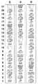
[図柄配列の説明]
図13は、左可変表示部23L、中可変表示部23C、右可変表示部23Rの各可変表示部に変動表示される図柄(識別情報あるいはシンボルマークともいう)の配列を示す図である。図では、左から順に、左可変表示部23L、中可変表示部23C、および右可変表示部23Rの図柄の種類が示されている。
【0109】
たとえば、左可変表示部23Lの場合には、「1」〜「5」の各図柄番号に、「JAC」、「ベル」、「スイカ」、「BAR」、「ベル」の各図柄が対応している。中可変表示部23Cの場合には、「1」〜「5」の各図柄番号に「チェリー」、「スイカ」、「JAC」、「ベル」、「模様付き7」の各図柄が対応している。これ以外の図柄としては、「模様なし7」が、左可変表示部23Lの図柄番号10、21、中可変表示部23Cの図柄番号12、右可変表示部23Rの図柄番号21に対応して設定されている。
【0110】
各可変表示部23L,23C,23Rでは、図示する図柄が図柄番号1〜21の順番で上から下に繰返し変動表示される。ただし、詳細は後述するが、ある種の条件が成立したときには、図31に示されるように、図柄番号と図柄との対応関係が異なる図柄配列で各可変表示部23L,23C,23Rが変動表示される。
【0111】
[入賞役の説明]
次に、入賞役について説明する。入賞役としては、ビッグボーナスと、小役と、リプレイと、レギュラーボーナスと、JAC役とが規定されている。
【0112】
(1) 「ビッグボーナス」は、ビッグボーナスゲームを複数回行なうことができる特典が付与される入賞役である。ビッグボーナス入賞は、可変表示部の停止結果が「模様なし7、模様なし7、模様なし7」または「模様付7、模様付7、模様付7」の組合わせとなった場合に発生する。ビッグボーナスゲームでは、払出枚数が多い小役入賞の当選確率が飛躍的に向上されるとともに、レギュラーボーナス入賞を発生させることが可能になる。このように、小役入賞の当選確率が向上されることから、ビッグボーナスゲームは別名「小役ゲーム」とも呼ばれる。
【0113】
ビッグボーナスゲームでレギュラーボーナス入賞が発生したときには、レギュラーボーナスゲームが複数回提供され、レギュラーボーナスゲームを消化した後に、再び、残りのビッグボーナスゲームが提供される。ビッグボーナスゲームは、レギュラーボーナス入賞が所定回数発生すること、または、予め定められた上限回数のビッグボーナスゲームを消化すること、のうち、いずれか早いほうの条件が成立するまで提供される。なお、本実施の形態では、レギュラーボーナスゲームが提供されている状態も含めて、「ビッグボーナス状態」と呼んでいる。
【0114】
(2) 「レギュラーボーナス」は、レギュラーボーナスゲームを複数回行なうことができる特典が付与される入賞役である。レギュラーボーナス入賞は、可変表示部の停止結果が「JAC、JAC、JAC」の組合わせとなった場合に発生する。この実施の形態の場合、レギュラーボーナス入賞は、ビッグボーナスゲーム中にのみ発生し得る。レギュラーボーナスゲームでは、レギュラーボーナスゲーム中に特有の入賞役であるJAC役のみが有効になり、かつ、極めて高い確率で、その入賞役が内部当選する。しかも、5つの入賞ラインのうちの1ラインのみが有効となり、目押しもやり易く、1枚賭けでゲームを消化できる。また、たとえば、JAC役の入賞役に入賞すれば、1ゲームで得ることが許容される最大の有価価値(たとえば、15枚のメダル相当)が付与される。レギュラーボーナスゲームは、入賞が所定回数発生すること、または、予め定められた上限回数のゲームを消化すること、のうち、いずれか早いほうの条件が成立するまで連続的に提供される。なお、JAC役の入賞図柄は「JAC」であるため、レギュラーボーナスゲーム中の入賞を特に“JAC入賞”という。
【0115】
(3) 「小役」は、ビッグボーナスゲームやレギュラーボーナスゲームのような特別なゲームの発生、またはリプレイゲームの発生を伴わない、有価価値(たとえば、クレジットまたはメダル)の付与のみを伴う入賞役である。
【0116】
スロットマシン1では、小役入賞として、小役1〜小役3が用意されている。このうち、小役1は、メダルの払出し数が15枚である“15枚小役”である。また、小役2は、メダルの払出し数が9枚である“9枚小役”であり、小役3は、メダルの払出し数が2枚である“2枚小役”である。
【0117】
小役1の図柄の組合わせは、「ベル、ベル、ベル」である。
小役2の図柄の組合わせは、「スイカ、スイカ、スイカ」である。この実施の形態では、この図柄「スイカ」の組合わせによる小役は、ストップボタン41L,41C,41Rの操作順序(以下、押し順という)が限定される特定の入賞役として設定されている。以下、この小役を特に、“停止順小役”という。この停止順小役では、たとえば、押し順が「左、中、右」として限定されたものであれば、ストップボタンを「左ストップボタン41L、中ストップボタン41C、右ストップボタン41R」の順で操作して可変表示部を「左可変表示部23L,中可変表示部23C,右可変表示部23R」の順で停止させないと、入賞役の図柄の組合せである「スイカ、スイカ、スイカ」が揃わないように制御される。したがって、小役「スイカ」が内部当選していても、その内部当選している小役に規定された押し順と異なる押し順でストップボタンが操作された場合、たとえ「スイカ」の小役が内部当選していても、「スイカ」が滑り、入賞が発生しないように制御される。
【0118】
“停止順小役”は、押し順が上記の「左、中、右」のタイプを含めて、「左、右、中」、「中、左、右」、「中、右、左」、「右、左、中」、「右、中、左」の6種類が規定されている。そして、各押し順別に内部当選フラグが用意されている。
【0119】
小役3の図柄の組合わせは、「チェリー、任意、任意」であり、左可変表示部23Lに「チェリー」が停止すると他の可変表示部の出目にかかわらず有効ライン毎に2枚のメダルが払出される。このように、「チェリー」は、中可変表示部および右可変表示部の出目とは無関係に入賞を発生させるので、単図柄と呼ばれる。
【0120】
(4) 「リプレイ」は、メダルあるいはクレジットを消費することなく次回のゲームを開始できるという特典が与えられる入賞役である。リプレイ入賞が発生した場合には所定時間の経過後、スタートレバー42の操作が有効となる。リプレイ入賞によって開始可能となるゲームを“リプレイゲーム”と呼ぶ。リプレイゲームが行なわれる際の賭数は、リプレイ入賞が発生した際のゲームの賭数と同一に設定される。リプレイの図柄の組合わせは、「JAC、JAC、JAC」であり、前述したように、レギュラーボーナスおよびJAC役の図柄の組合わせと同一である。
【0121】
(5) さらに、レギュラーボーナスゲームにのみ有効となるJAC役は、メダルの払出数が15枚である“15枚小役”である。
【0122】
[コマンドの説明]
図14は、1ゲーム中に遊技制御用マイクロコンピュータ101から表示制御用マイクロコンピュータ201へ送信されるコマンドの一例を説明するための図である。
【0123】
各コマンドは、たとえば、ヘッダ、コマンド種別を示すデータ、および情報部データを含む2バイトのデータから構成されている。図において、コマンド名称の下の“かっこ書き”は、そのコマンドが含む情報部データを示す。たとえば、スタート画面レイアウトコマンドの場合は、情報部データとして、スタート画面のレイアウト、告知の有無、および告知対象の入賞役の計3種類のデータを含むことが示されている。
【0124】
また、図において、矢印(→)の左下にコマンド名称が示されるコマンドは、1ゲーム中に必ず送信される必須のコマンドである。一方、矢印の右下にコマンド名称が示されるコマンドは、1ゲーム中に送信される場合と送信されない場合とがある選択的なコマンドである。
【0125】
1ゲーム中、コマンドは、図の上から下へ示す順にゲームの進行に応じて表示制御用マイクロコンピュータ201へ送信される。
【0126】
スタート画面レイアウトコマンドは、スタートレバー42の操作によってゲームが開始されたときに表示する画面のレイアウトを指定するコマンドである。以下、この画面のレイアウトを“スタート画面のレイアウト”、あるいは“スタート画面レイアウト”という。スタート画面のレイアウトは、図1に示したノーマルレイアウトを含めて予め複数種類用意されており、その種類によって、可変表示部23L,23C,23Rおよび演出表示部22のサイズ、ビッグボーナス告知の表示機能の有無が異なる。
【0127】
スタート画面レイアウトコマンドには、画面種類(各表示部のレイアウト)を指定するデータの他、告知の有無、および告知対象の入賞役の情報部データが含まれる。これら2つのデータは、指定した種類の画面において、ゲームの開始時に内部当選の告知をするか否か、および、内部当選の告知をするときの告知対象の入賞役を示すデータである。
【0128】
ただし、この実施の形態では、簡単のため、スタート画面による告知対象となる入賞役がビッグボーナスのみである場合を説明している。また、スタート画面のレイアウトと告知の有無との対応関係も、図33を用いて後述するように、「ノーマルレイアウト:告知なし」、「告知レイアウト:告知あり」、「全面キャラクタ告知レイアウト:告知あり」としており、「スタート画面のレイアウト」の種類で「告知(ビッグボーナス当選告知)の有無」が定まるものを例として説明する。
【0129】
なお、スタート画面レイアウトコマンドは、いわゆる“ガセ”の告知をするためにも利用される。すなわち、遊技制御用マイクロコンピュータ101は、実際には内部当選していない入賞役ついて、[告知有り]とするスタート画面レイアウトコマンドを送信する場合がある。
【0130】
可変表示部拡大コマンドは、可変表示部を画面一杯に拡大することを指令するコマンドである。この実施の形態では、たとえば、ビッグボーナス当選フラグが持越されたゲームが開始されるときに送信される。換言すれば、ビッグボーナスが内部当選したゲームで、ビッグボーナスが発生しなかったときに、ビッグボーナスが発生するまで、それ以降のゲームの開始時に送信される。したがって、このコマンドに従って、ゲーム開始時に画面が変化することによって、ビッグボーナス当選していることが遊技者に告知されることになる。また、それゆえ、この画面による告知の信頼度は100%である。
【0131】
以下の説明では、この可変表示部拡大コマンドに従ってゲーム開始時に表示される画面のレイアウト(1種類:図32(D))と、先に説明したスタート画面レイアウトコマンドに従ってゲーム開始時に表示される画面のレイアウト(3種類:図32(A)、(B)、(C))とをまとめて“スタート画面のレイアウト”、あるいは“スタート画面レイアウト”という。
【0132】
なお、可変表示部拡大コマンドは、可変表示部23L,23C,23Rのいずれか2箇所に図柄が停止した段階で、入賞役の図柄の組合せとなる条件を満たすリーチ状態となったときに送信されるようにしてもよい。あるいは、リーチ状態となったときに送信することに代えて、あるいはこれに加えて、可変表示部23L,23C,23Rにおける図柄の変動開始から変動終了までの間でランダムな時期に、可変表示部拡大コマンドが送信されるようにしてもよい。
【0133】
変動開始コマンドは、可変表示部23L,23C,23Rにおいて図柄の変動を開始させることを指示するコマンドである。表示制御用マイクロコンピュータ201は、変動開始コマンドを受けて、可変表示部23L,23C,23Rでの図柄の変動を開始させる。
【0134】
目押し図柄コマンドは、目押しの対象とするべき図柄、換言すれば、内部当選している入賞役の図柄を報知することを指令するコマンドである。目押し図柄コマンドには、[目押し対象の図柄]を示すデータが含まれている。この目押しコマンドは、遊技制御用マイクロコンピュータ101が、内部当選している入賞役の図柄を報知することを決定したことに基づいて送信される。スタート画面レイアウトコマンドとは異なり、 “ガセ”で目押し対象の図柄を通知することはない。しかしながら、“ガセ”で目押し対象の図柄を通知する場合もあるようにしてもよい。すなわち、遊技制御用マイクロコンピュータ101は、実際には内部当選していない入賞役の図柄について、[目押し対象の図柄]として、目押し図柄コマンドを送信するようにしてもよい。
【0135】
表示制御用マイクロコンピュータ201は、目押しコマンドを受けて、目押し対象の図柄を表示画面上で所定の表示態様で報知する。目押し対象の図柄を表示画面上で報知することを“目押しナビゲーション”という。
【0136】
第1〜第3停止順コマンドは、“ストップボタン41L,41C,41Rの操作順”、換言すれば、“可変表示部23L,23C,23Rの停止順”が予め定められた“押し順入賞役”が内部当選しているときに、その押し順入賞役についての入賞を発生させるためのストップボタン41L,41C,41Rの操作順”を通知するためのコマンドである。第1停止順コマンドによって、[第1停止(最初に停止)させる可変表示部]が通知される。第2停止順コマンドによって、[第2停止(次に停止)させる可変表示部]が通知される。第3停止順コマンドによって、[第3停止(最後に停止)させる可変表示部]が通知される。
【0137】
表示制御用マイクロコンピュータ201は、この第1〜第3停止順コマンドを受け、ストップボタン41L,41C,41Rの操作順を特定できる報知画像を表示画面21に表示する。このように、内部当選している押し順小役に規定されている押し順を表示画面上で報知することを“押し順ナビゲーション”という。
【0138】
第1〜第3停止順コマンドは、押し順入賞役が内部当選したときに常に送信されるものではなく、押し順入賞役が内部当選する都度、それらのコマンドを送信するか否かが遊技制御用マイクロコンピュータ101によって決定される。したがって、押し順入賞役が内部当選しているゲームにおいて、ストップボタン41L,41C,41Rの操作順が報知される場合と報知されない場合とがある。
【0139】
第1停止順コマンドは、3つの可変表示部が変動しているときに送信される。第2停止順コマンドは、1つの可変表示部が停止し2つの可変表示部が変動しているときに送信される。第3停止順コマンドは、2つの可変表示部が停止し1つの可変表示部が変動しているときに送信される。
【0140】
第1〜第3停止コマンドは、可変表示部の変動の停止を指令するコマンドである。各コマンドには、[変動を停止させる可変表示部]、および[図柄の停止位置]の情報が含まれる。なお、[図柄の停止位置]の情報は、たとえば、可変表示部の上段、中段、下段の図柄表示位置のうち、上段に表示させる図柄ナンバーから成る。表示制御用マイクロコンピュータ201は、第1〜第3停止コマンドを受信したタイミングで、コマンドに従う可変表示部に、コマンドに従う図柄を停止させる。
【0141】
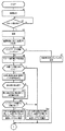
[フローチャートの説明]
図15〜図18は、1ゲーム中に遊技制御用マイクロコンピュータ101が実行する処理の概要を説明するためのフローチャートである。このフローチャートにおいては、最初に賭数設定処理が実行される(S1)。この処理は、メダルの投入操作、または、1枚BETボタン43あるいはMAXBETボタン44の操作による遊技者の賭け操作に応じて、賭数を設定する処理である。
【0142】
次に、スタート操作(スタートレバー42の操作)が検出されたこと(S2:YES)を条件として、抽選処理が実行される(S3)。抽選処理では、入賞の発生を許容するか否か、およびどの入賞役の発生を許容するか、が決定される。より具体的には、スタート操作が検出されたタイミングで乱数が抽出され、賭数に応じた入賞判定用テーブルと、抽出された乱数とが比較される。入賞判定用テーブルには、当選値が入賞役(ビッグボーナス、レギュラーボーナス、小役、リプレイ、JAC役)別に記憶されており、抽出された乱数がいずれかの当選値と一致するか否かが判断され、当選の有無が判定される。
【0143】
次に、抽選処理において当選があった場合には、その当選があった入賞役(ビッグボーナス、レギュラーボーナス、停止順小役を含む小役、リプレイ、JAC役)に対応した当選フラグが設定される(S4)。
【0144】
次に、ビッグボーナス持越しフラグがONしているか否かが判断される(S5)。ビッグボーナス持越しフラグは、S3の抽選処理においてビッグボーナスが当選したにもかかわらず、そのゲームでビッグボーナスが発生しなかったときにONされるフラグである。したがって、ビッグボーナス持越しフラグが設定されているということは、前回以前のゲームでビッグボーナス当選したものの、未だビッグボーナスが発生しておらずビッグボーナス当選フラグが持越されていることを意味する。
【0145】
S5でビッグボーナス持越しフラグがONしていると判断されたときには、可変表示部拡大コマンドが設定される(S7)。これにより、スタート操作の検出に基づいて表示されるスタート画面レイアウトが、可変表示部が全面に拡大表示される “全面可変表示部レイアウト”に決定される。
【0146】
ビッグボーナス持越しフラグがONしていないと判断されたときは、スタート画面選択用乱数が抽出される(S6)。スタート画面選択用乱数は、スタート操作の検出に基づいて表示するスタート画面レイアウトの種類を決定するために用いる乱数である。この乱数は、遊技制御基板100の遊技制御用マイクロコンピュータ101により実行される制御プログラムで生成されるソフト乱数、または遊技制御用マイクロコンピュータ101の外部に設けた乱数発生回路から供給されるハード乱数であり、0〜99の範囲で繰返し更新されている。抽出されたスタート画面選択用乱数は、一時、遊技制御用マイクロコンピュータ101格納され、S13、S14の処理において読出される。
【0147】
次に、当選フラグが設定されているか否かが判断される(S8)。いずれかの入賞役について、当選フラグが設定されているときには、目押し図柄の告知をするか否かが決定される(S9)。S9では、決定用の所定の乱数が抽出されて、その乱数の値に基づいて、目押し図柄の告知の有無がランダムに決定される。
【0148】
なお、ここで告知有りと決定されたときには、設定されている当選フラグの入賞役に対応する入賞図柄が表示画面において所定の態様で報知される。その態様については、図26〜図31を用いて後述する。
【0149】
S9の後、停止順小役が当選しているか否か、すなわち、停止順小役に対応する当選フラグが設定されているか否かが判断される(S10)。そして、停止順小役に対応する当選フラグが設定されているときには、その停止順の告知の有無が決定される(S11)。S11では、決定用の所定の乱数が抽出されて、その乱数の値に基づいて、停止順小役の告知の有無がランダムに決定される。
【0150】
なお、ここで告知有りと決定されたときには、当選フラグが設定されている停止順小役の停止順が表示画面において所定の態様で報知される。その態様については、図22〜図25を用いて後述する。
【0151】
次に、ビッグボーナス当選フラグが設定されているか否か、すなわち、今回のゲームにおいて、ビッグボーナス入賞の発生が許容されているか否かが判断される(S12)。
【0152】
ビッグボーナス当選フラグが設定されているときには、当選フラグ有に対応するテーブルが参照される。そして、そのテーブルの中から、S6で抽出されたスタート画面選択用乱数に対応付けられたスタート画面レイアウトが選択される(S12)。
【0153】
一方、S12においてビッグボーナス当選フラグが設定されていないと判断されたとき、およびS8においていずれの当選フラグも設定されていないと判断されたときには、当選フラグ無に対応するテーブルが参照され、そのテーブルの中から、S6で抽出されたスタート画面選択用乱数に対応付けられたスタート画面レイアウトが選択される(S14)。
【0154】
S12、S14において参照されるテーブルとスタート画面選択用乱数との関係については、図33を用いて後述する。
【0155】
次に、可変表示部拡大コマンドが設定されているか否かが判断される(S21)。この実施の形態では、1ゲーム毎に、必ず、可変表示部拡大コマンドまたはスタート画面レイアウトコマンドが設定される。
【0156】
可変表示部拡大コマンドが設定されているときには、その設定された(S7で設定)可変表示部拡大コマンドが表示制御用マイクロコンピュータ201へ送信される(S22)。表示制御用マイクロコンピュータ201は、このコマンドに応じたレイアウトのスタート画面、すなわち、全面に可変表示部23L,23C,23Rが割り振られたレイアウトのスタート画面を表示する。なお、そのスタート画面の具体例は、図32(D)に示されている。
【0157】
一方、可変表示部拡大コマンドが設定されていないときには、スタート画面レイアウトコマンドが表示制御用マイクロコンピュータ201へ送信される(S21)。このコマンドには、S13またはS14において決定されたスタート画面のレイアウトの種類、告知対象の入賞役(この実施の形態ではビッグボーナス)の情報が含まれる。表示制御用マイクロコンピュータ201は、このコマンドに応じたレイアウトのスタート画面を表示する。なお、このとき、表示されるスタート画面の具体例は、図32(A)、(B)、(C)に示されている。
【0158】
次に、変動開始コマンドが送信される(S24)。表示制御用マイクロコンピュータ201は、このコマンドを受信して、可変表示部23L,23C,23Rにおいて図柄の変動を開始させる。
【0159】
次に、目押し図柄を告知(図柄ナビゲーション)することが決定されているか否かが判断される(S25)。S9において、目押し図柄を告知することが決定されているときには、S9の決定に応じた目押し図柄コマンドが送信される(S26)。
【0160】
この目押し図柄コマンドには、目押し対象の図柄を示す情報が含まれている。表示制御用マイクロコンピュータ201は、この目押し図柄コマンドに応じて、表示画面に目押し対象の図柄を所定の態様で報知する制御を行なう(図26〜図31を用いて後述)。
【0161】
次に、停止順を告知することが決定されているか否かが判断される(S27)。S11において、停止順を告知(停止順ナビゲーション)することが決定されているときには、第1停止順コマンドが送信される(S28)。この第1停止順コマンドには、複数の可変表示部のうち、最初に停止させる第1停止可変表示部を示す情報が含まれている。表示制御用マイクロコンピュータ201は、この第1停止順コマンドに対応する第1可変表示部を所定の態様で変化させ、最初に停止させるべき可変表示部を報知する(図22〜図25を用いて後述)。
【0162】
S28の処理の後、あるいはS27においてNOと判断された後、停止操作無効期間が経過したか否かが判断される(S29)。この停止操作無効期間は、可変表示部23L,23C,23Rで図柄の一斉変動が開始されてから、図柄の変動速度が加速し、やがて、その変動速度が一定速度に達するまでの期間である。
【0163】
停止操作無効期間が経過したと判断されたときには、第1停止操作が検出されたか否かが判断される(S30)。まだ、第1停止操作が検出されていない場合には、操作待ち時間が経過したか否かが判断される(S31)。
【0164】
この実施の形態では、可変表示部23L,23C,23Rで図柄の一斉変動が経過してから予め定められた“操作待ち時間”が計時しても、ストップ操作が検出されないストップボタン41L,41C,41Rが存在するときに、そのストップボタンに対応する可変表示部が自動的に停止制御される。したがって、“操作待ち時間”の経過は、各ストップ操作に対応するS31、S44、S50の各々において判断される。
【0165】
操作待ち時間が経過するまでに1つ目の可変表示部を停止させる第1停止操作が検出されたときには、停止位置決定処理が実行される(S32)。この停止位置決定処理では、第1停止操作に対応する可変表示部について、前述した“引込み制御”が実行されて、可変表示部の図柄の変動位置、および内部当選状況に応じて、第1停止操作に対応する可変表示部に停止させる図柄の種類が決定される。
【0166】
S32の停止位置決定処理で決定された図柄位置は、第1停止コマンドとして送信される(S33)。表示制御用マイクロコンピュータ201は、この第1停止コマンドに基づいて、対応する可変表示部に所定の図柄を停止させる制御を行なう。
【0167】
その後、変動中の残り2つの可変表示部の一方を停止させる第2停止に対応する表示制御を指令するために、「S41、S42、S43〜S46」の処理が実行される。この処理は、対象の可変表示部が相違する点を除いては、すでに説明した、「S27、S28、S30〜S33」と処理内容が同様であるので、説明を繰返さない。
【0168】
次に変動中の最後の可変表示部を停止させる第3停止に対応する表示制御を指令するために、「S47、S48、S49〜S51」の処理が実行される。この処理は、対象の可変表示部が相違する点を除いては、すでに説明した、「S27、S28、S30〜S32」と処理内容が同様であるので、説明を繰返さない。
【0169】
ただし、第3停止においては、S51において実行された停止位置決定処理により定められた図柄停止位置が第3停止コマンドとして送信される前に、その定められた図柄停止位置に図柄を停止させると有効ライン上に“停止順小役”の図柄の組合せが揃うことになるか否かが判断される(S52)。
【0170】
そして、“停止順小役”の図柄の組合せが揃わない場合には、S51で定められた図柄停止位置が第3停止コマンドとして送信される(S54)。
【0171】
一方、S52において、“停止順小役”の図柄の組合せが揃うと判断されたときには、その図柄の組合せおよび押し順に対応する“停止順小役”が内部当選内容と一致しているか否かが判断され(S53)、一致していないと判断されたときには、再度、S51で停止位置決定処理が実行されて、他の図柄停止位置が選択される。これに対して、一致しているときには、S51で定められた図柄停止位置が第3停止コマンドとして送信される(S54)。
【0172】
次に、入賞判定処理が実行される(S61)。この入賞判定処理は、停止図柄によって入賞が発生したか否かを判定する処理である。次に、払出し処理が実行され(S62)、入賞判定処理による入賞判定に応じたメダルあるいはクレジットを払出す処理が行なわれる。
【0173】
次に、ビッグボーナス入賞が発生したか否かが判断される(S63)。ビッグボーナス入賞が発生したと判断されたときには、ビッグボーナス持越しフラグが設定されていれば(S64でYES)、ビッグボーナス持越しフラグがOFFにされた後(S65)、ビッグボーナス当選フラグを含めてすべての当選フラグがOFFにされる(S66)。S64でYESのときには、つまりは、今回発生したビッグボーナスが前回のゲーム以前で設定されたビッグボーナス当選フラグによるものであるということになる。
【0174】
S63でビッグボーナス入賞が発生していないと判断されたときには、ビッグボーナス当選フラグがONしているか否かが判断される(S67)。ここで、YESと判断されたときには、すなわち、ビッグボーナス当選フラグが設定されているゲームでビッグボーナス入賞が発生しなかったことになる。この場合には、ビッグボーナス持越しフラグがOFFであることを条件に(S68:YES)、ビッグボーナス持越しフラグがONにされる(S69)。
【0175】
なお、S68でNOの場合とは、すなわち、今回のゲーム以前のゲームで、すでにビッグボーナス持越しフラグがONしている場合である。ビッグボーナス持越しフラグがONということは、次回のゲームにビッグボーナス当選フラグが持越されるということであり、S69の後(またはS68でNOと判断された後)、ビッグボーナス当選フラグを残して、すべての当選フラグがOFFにされる(S70)。その後、図15の先頭に処置が戻る。
【0176】
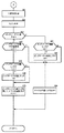
図19〜図21は、表示制御用マイクロコンピュータ201が実行するゲーム表示処理を説明するためのフローチャートである。このゲーム表示処理が実行されることにより、1ゲームにおいてさまざまな画像が表示画面21に表示される。
【0177】
ゲーム表示処理では、1ゲームが開始された後、最初に、スタート画面レイアウトコマンドの受信の有無が判断される(SUB1)。スタート画面レイアウトコマンドが送信されてこないときには、可変表示部拡大コマンドの受信の有無が判断される(SUB11)。そして、いずれか一方のコマンドの受信が確認されるまで、両判断が繰返し実行される。
【0178】
SUB11において、可変表示部拡大コマンドの受信ありと判断されたときには、画面全面に可変表示部を拡大表示する切換え制御が実行される(SUB12)。これにより、表示画面のレイアウトは、ゲーム開始前のノーマルレイアウト(図1参照))から“全面可変表示部レイアウト”(図32(D)参照)に変更される。前述したように、ビッグボーナス当選フラグが持越された場合に、この全面可変表示部レイアウトで画面表示されるのであり、これにより、遊技者にビッグボーナス当選していることが告知されることになる。なお、全面可変表示部レイアウトのデータは、表示制御用マイクロコンピュータ201のROM203内に構成される画面テーブルに記憶されている。
【0179】
次に、変動開始コマンドの受信有りと判断されたことを条件に(SUB13でYES)、拡大表示された可変表示部23L,23C,23Rで図柄を一斉に変動開始させる制御が実行される(SUB14)。
【0180】
一方、SUB1において、スタート画面レイアウトコマンドの受信ありと判断されたときには、そのスタート画面レイアウトコマンドに対応するスタート画面のレイアウトを画面テーブルから選択する処理が実行される(SUB2)。なお、画面テーブルは、表示制御用マイクロコンピュータ201内のROM203内に記憶されている。
【0181】
次に、SUB2により選択されたスタート画面レイアウトに画面21の画像を切換える処理が実行される(SUB3)。これにより、画面21のレイアウトは、図32(A)、(B)、(C)のいずれかになる。なお、このうち、図32(A)は、図1にも示されるノーマルレイアウトであり、このノーマルレイアウトがスタート画面として選択されたときには、ゲーム開始の前後で画面のレイアウトが変化しない。
【0182】
次に、選択されたスタート画面が告知付の画面であるか否かが判断され(SUB4)、告知付の画面である場合には、そのスタート画面に対応した態様で告知演出が開始される(SUB5)。なお、告知付きのスタート画面は、図32(A)、(B)、(C)のうちの(B)および(C)である。
【0183】
次に、変動開始コマンドが受信されたか否かが判断される(SUB6)。変動開始コマンドを受信したときには、各可変表示部で図柄の変動を開始させるが、スタート画面レイアウトの種類が表示画面全面に告知キャラクタを表示する“全面キャラクタ告知レイアウト”(図32(C)参照)であるときには、そのキャラクタによる告知演出の表示が終了した後に可変表示部23L,23C,23Rを表示させて図柄の一斉変動を開始させる必要がある。
【0184】
そこで、SUB7では、スタート画面レイアウトが“全面キャラクタ告知レイアウト”であるか否かが最初に判断される。そして、“全面キャラクタ告知レイアウト”であるときには、告知演出を行なう時間として予め定められたスタート画面表示時間が経過した後に(SUB9でYES)、スタート画面のレイアウトを図1のノーマルレイアウトに戻してから可変表示部23L,23C,23Rで図柄の一斉変動を開始させる(SUB10)。
【0185】
一方、SUB7において、スタート画面が“全面キャラクタ告知レイアウト”でないと判断されたときには、即座に、各可変表示部で図柄の一斉変動を開始させる(SUB8)。この場合、たとえば、演出表示部22において所定の告知演出の表示がされつつ、可変表示部23L,23C,23Rにおいて図柄が変動表示される(図32(B)参照)。あるいは、スタート画面として“ノーマルレイアウト”が選択されていたときには、告知演出を伴なうことなく、可変表示部23L,23C,23Rにおいて図柄が変動表示される(図32(A)参照)。
【0186】
SUB10において、表示画面がノーマルレイアウト(図1参照)の構成に切り戻された後(スタート画面がノーマルレイアウトのときには切換え前後でレイアウトは変化しない)、目押し図柄コマンドが受信されたか否かが判断される(SUB21)。
【0187】
目押し図柄コマンドが受信されたときには、そのコマンドに従い、目押し図柄を所定の態様で報知する表示制御が実行される(SUB22)。なお、目押し図柄の報知態様の具体例は、図27〜図31を用いて後述する。
【0188】
次に、第1停止順コマンドが受信されたか否かが判断される(SUB23)。そして、第1停止順コマンドが受信されたときには、そのコマンドに応じて停止順を報知する表示制御が実行される(SUB24)。なお、停止順の報知態様の具体例は、図22〜図25を用いて後述する。
【0189】
次に、第1停止コマンドの受信を待ち(SUB25)、受信した第1停止コマンドに対応する可変表示部に、そのコマンドによって指定された図柄を停止表示させる処理が実行される(SUB26)。
【0190】
次に、第2停止順コマンドが受信されたか否かが判断される(SUB27)。そして、第2停止順コマンドが受信されたときには、そのコマンドに応じて停止順を報知する表示制御が実行される(SUB28)。
【0191】
次に、第2停止コマンドの受信を待ち(SUB29)、受信した第2停止コマンドに対応する可変表示部に、そのコマンドによって指定された図柄を停止表示させる処理が実行される(SUB30)。
【0192】
次に、第3停止順コマンドが受信されたか否かが判断される(SUB41)。そして、第3停止順コマンドが受信されたときには、そのコマンドに応じて停止順を報知する表示制御が実行される(SUB42)。
【0193】
次に、第3停止コマンドの受信を待ち(SUB43)、受信した第3停止コマンドに対応する可変表示部に、そのコマンドによって指定された図柄を停止表示させる処理が実行される(SUB44)。この処理が実行されることにより、すべての可変表示部に図柄が停止表示された状態となる。
【0194】
次に、画面がノーマルレイアウト以外であるか否かが判断され(SUB45)、ノーマルレイアウト以外であるときには、このSUB45においてYESと判断され、画面レイアウトをノーマルレイアウトに切換える制御が実行され(SUB46)、ゲーム表示処理が終了する。SUB46により、表示画面のレイアウトが、図1に示されるノーマルレイアウトに切り戻される。
【0195】
[押し順ナビゲーションの表示例]
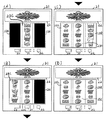
次に、図22〜図25を用いて、押し順ナビゲーションの具体的な表示例を説明する。図22〜図25には、可変表示部23L,23C,23Rの画像を変化させることによって、内部当選している押し順小役の押し順を報知する表示例が示されている。なお、図22〜図25のいずれの表示パターンにおいても、停止順が「中→左→右」である場合が例示されている。また、図22〜図25のいずれにおいても、(A)は第1停止操作前の表示態様例であり、(B)は第2停止操作前の表示態様例であり、(C)は第3停止操作前の表示態様例であり、(D)はすべての可変表示部に図柄が停止したときの表示態様例である。各図においては、可変表示部23L,23C,23Rの両脇に表示される各表示部24〜29の図示を省略してある。
【0196】
図22は、停止順が到来している可変表示部を拡大表示させるとともに停止順が到来していない可変表示部を縮小表示させることにより押し順を報知する表示パターンを示す図である。
【0197】
この拡大縮小パターンでは、ノーマルレイアウト(図1参照)により各可変表示部で図柄の一斉変動が開始された後、最初に、第1停止させる中可変表示部23Cのみが拡大表示され、それ以外の可変表示部23L,23Rは縮小表示される(図22(A))。また、可変表示部の拡大に伴ない、演出表示部22は、上下方向に縮小される。このような表示態様の変化により、遊技者は、第1停止させるべき可変表示部が中可変表示部23Cであることを認識できる。また、停止させるべき可変表示部が拡大表示され、それ以外の可変表示部23L,23Rは縮小表示されているために、相対的に停止させるべき可変表示部が目立ち、より目押し操作しやすくなる。
【0198】
中可変表示部23Cが停止表示された後には、第2停止させる左可変表示部23Lが拡大表示される(図22(B))。このとき、既に停止表示された中可変表示部23Cは、未だ可変表示中の右可変表示部23Rと同様に、縮小表示されている。
【0199】
左可変表示部23Lが停止表示された後は、第3停止させるべき右可変表示部23Rのみが拡大表示される(図22(C))。また、このとき、既に図柄が停止表示されている左可変表示部23Lおよび中可変表示部23Cは、縮小表示される。
【0200】
その後、右可変表示部23Rの停止操作が検出されると、右可変表示部23Rに図柄が停止表示されるとともに、図22(D)に示されるように、すべての可変表示部のサイズが変動開始前のサイズに戻るとともに演出表示部22も元のサイズに戻り、画面構成が図1に示されるノーマルレイアウトに変化する。
【0201】
図23は、停止順が到来している可変表示部をスクロール方向に伸張させることにより、押し順を報知する表示パターンを示す図である。
【0202】
図23に示される伸張パターンでは、停止順が到来している可変表示部のみがスクロール方向に伸張されるため、図22の表示パターンと同様に、遊技者が目押し操作をしやすいという利点がある。図23に示される伸張パターンにおいても、停止順が到来した可変表示部が(A)、(B)、(C)、(D)の順に変化して、停止順が遊技者に報知される。なお、この図23の伸張パターンでは、停止順が到来していない可変表示部および既に図柄が停止表示された可変表示部については、縮小表示等されることはない。
【0203】
図24は、変動表示中の可変表示部のうち、停止順が到来している可変表示部以外を遮蔽(隠蔽)画像23aによって遮蔽することにより、押し順を報知する表示パターンを示す図である。
【0204】
図24に示される遮蔽パターンでは、(A)、(B)、(C)、(D)の順に変化して、図柄が変動表示されている可変表示部のうち、停止順が到来している可変表示部以外が図示のように遮蔽画像23aによって遮蔽される。なお、図24では、図柄がまったく見えなくなるように遮蔽画像23aによって遮蔽したが、これに代えて、可変表示部内の一部を遮蔽画像によって遮蔽し、可変表示部内の一部が遮蔽画像の脇から覗くようにして変動中の図柄の一部が見えるようにしてもよい。あるいは、遮蔽画像を、その下に遮蔽される図柄がやや透けて見えるようなマスク(たとえば、グレーのマスク)で構成してもよい。
【0205】
図25は、図柄が変動している可変表示部のうち、停止順が到来している可変表示部以外を半透明表示することにより、押し順を報知する表示パターンを示す図である。
【0206】
図25において、破線で示される図柄は、半透明で表示されている図柄である。図25の半透明パターンでは、(A)、(B)、(C)、(D)の順に変化して、図柄が変動表示されている可変表示部のうち、停止順が到来している可変表示部以外が半透明表示される。なお、図柄を半透明化するのではなく、可変表示部から完全に図柄を消すようにしてもよい。あるいは、停止順が到来していない図柄を半透明化することに代えて、停止順が到来した図柄の色彩(明度、彩度、色調)と、停止順が到来していない図柄の色彩とを異ならせるようにしてもよい。
【0207】
スロットマシン1の押し順ナビゲーションとしては、上記拡大縮小パターン、伸張パターン、遮蔽パターン、半透明パターンのうちのいずれを採用してもよい。また、複数パターンを記憶手段(たとえば、表示制御用マイクロコンピュータ201)に記憶しておき、表示制御手段の一例である表示制御用マイクロコンピュータ201がいずれか1つを選択して表示するようにしてもよい。このときには、表示制御用マイクロコンピュータ201が抽出した乱数に基づいて、表示制御用マイクロコンピュータ201が押し順ナビゲーションに用いるパターンを複数種類の中から選択する構成が考えられる。
【0208】
上記のように、本実施の形態に関わるスロットマシンでは、遊技者がゲーム中に注目している可変表示部23L,23C,23Rの画像を変化させることによって、内部当選している押し順小役の押し順を報知することができるために、遊技者に押し順を理解させ易い。また、これまでにない、斬新な押し順ナビゲーションによって、演出効果の高いゲームを提供できる。
【0209】
[目押しナビゲーションの表示例]
次に、図26〜図31を参照して、目押しナビゲーションの具体的な表示例を説明する。図26〜図30には、可変表示部23L,23C,23Rの画像を変化させることによって、目押し図柄を報知する表示例が示されている。各図においては、可変表示部23L,23C,23Rの両脇に表示される各表示部24〜29の図示を省略してある。なお、図31は、図30に示される表示例を採用するときの図柄配列表を示す。
【0210】
図26〜図30のいずれにおいても、報知対象の目押し図柄が「ベル」であり、かつ、可変表示部の図柄の変動が停止する順序が「左→中→右」である場合が例示されている。また、図26〜図30のいずれにおいても、(A)は第1停止操作前の表示態様例であり、(B)は第2停止操作前の表示態様例であり、(C)は第3停止操作前の表示態様例であり、(D)はすべての可変表示部に図柄が停止したときの表示態様例である。
【0211】
図26は、目押し図柄を拡大させ、それ以外を縮小させる表示パターンを示す図である。この拡大縮小パターンでは、可変表示部23L,23C,23Rで図柄が一斉に変動開始した後、(A)に示されるように、目押し報知対象の図柄「ベル」のみが各可変表示部23L,23C,23Rで拡大表示されるとともに、それ以外の図柄が縮小表示される。
【0212】
その後、第1停止操作(左可変表示部)が検出されると、第1停止操作に対応する可変表示部での図柄の変動が停止する。このとき、(B)に示されるように、図柄が停止した可変表示部に表示される図柄のサイズは、元に戻る。以下、同様にして、第2停止操作、第3停止操作が検出されることに応じて、(C)、(D)に示されるように、対応する可変表示部で図柄の変動が停止する。
【0213】
このような表示態様の変化により、遊技者は、目押し対象を認識できる。また、目押し対象の図柄が拡大表示され、それ以外の図柄が縮小表示されているために、目押し対象の図柄が目立ち、より目押し操作しやすくなる。
【0214】
図27は、目押し図柄のみを拡大させ、それ以外の図柄については表示サイズを変化させない表示パターンを示す図である。この拡大パターンは、図26に示した拡大縮小パターンと比較して、目押し対象となる図柄以外について表示サイズを変化させない点が異なる。
【0215】
図28は、目押し図柄以外の図柄を遮蔽する表示パターンを示す図である。この遮蔽パターンでは、可変表示部23L,23C,23Rで図柄が一斉に変動開始した後、(A)に示されるように、目押し報知対象の図柄「ベル」以外の図柄が遮蔽(隠蔽)画像23bによって遮蔽される。
【0216】
その後、第1停止操作(左可変表示部)が検出されると、第1停止操作に対応する可変表示部での図柄の変動が停止する。このとき、(B)に示されるように、図柄が停止した可変表示部の遮蔽画像23bは除去される。以下、同様にして、第2停止操作、第3停止操作が検出されることに応じて、(C)、(D)に示されるように、対応する可変表示部で図柄の変動が停止し、最終的には遮蔽画像23bが表示されない状態で表示結果が導出表示される。
【0217】
このような表示態様の変化により、遊技者は、目押し対象を認識できる。また、目押し対象の図柄以外が遮蔽されるために、目押し対象の図柄が目立ち、より目押し操作しやすくなる。
【0218】
なお、図28では、図柄がまったく見えなくなるように遮蔽画像23bによって遮蔽したが、これに代えて、可変表示部内の一部を遮蔽画像によって遮蔽し、図柄の一部が遮蔽画像の脇から覗くようにして変動中の図柄の一部が見えるようにしてもよい。あるいは、遮蔽画像を、その下に遮蔽される図柄がやや透けて見えるようなマスク(たとえば、グレーのマスク)で構成してもよい。
【0219】
図29は、目押し図柄以外の図柄を半透明化する表示パターンを示す図である。この半透明パターンでは、可変表示部23L,23C,23Rで図柄が一斉に変動開始した後、(A)に示されるように、目押し報知対象の図柄「ベル」以外の図柄が半透明で表示される。
【0220】
その後、第1停止操作(左可変表示部)が検出されると、第1停止操作に対応する可変表示部での図柄の変動が停止する。このとき、(B)に示されるように、図柄が停止した可変表示部での半透明表示は行なわれなくなり、可変表示部に停止しているすべての図柄がベルと同様に表示される。以下、同様にして、第2停止操作、第3停止操作が検出されることに応じて、(C)、(D)に示されるように、対応する可変表示部で図柄の変動が停止し、最終的には半透明表示されない状態で表示結果が導出表示される。
【0221】
なお、半透明表示することに代えて、目押し対象の図柄を完全に見えなくするようにしてもよい。あるいは、図柄を半透明化することに代えて、目押し対象の図柄の色彩(明度、彩度、色調)と、目押し対象でない図柄の色彩とを異ならせるようにしてもよい。
【0222】
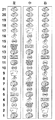
図30は、可変表示部における図柄の配置パターンを変化させ、目押し対象の図柄を連続的に表示させる表示パターンを示す図である。この連続表示パターンでは、図柄の変動が停止された可変表示部については、図13の図柄配列(ノーマル図柄配列という)が用いられるが、図柄が変動中である可変表示部については、目押し報知対象である図柄(この例ではベル)を連続配置させた図31の図柄配列(連続図柄配列という)が用いられる。
【0223】
図31の連続図柄配列の特徴は、配置位置が異なるものの、各可変表示部に割当てられた図柄が、図13のノーマル図柄配列と異ならない点にもある。たとえば、左可変表示部についていえば、図13、図31の図柄配列の双方とも、「ベル」の数が5、「模様付き7」の数が1、「模様なし7」の数が2、「スイカ」の数が5、「JAC」の数が4、「BAR」の数が2、「チェリー」の数が2である。
【0224】
したがって、図31の連続図柄配列は、図13のノーマル図柄配列を基準にして、各可変表示部毎に、図柄番号と図柄の種類との対応関係を変化させたものであるといえる。
【0225】
この連続パターンでは、図柄の一斉変動が開始されたときには、すべての可変表示部23L,23C,23Rにおいて図31の連続配列が採用される。そして、(A)に示されるように、可変表示部23L,23C,23Rにおいて、目押し報知対象の図柄「ベル」が連続的に現れるように、図柄がスクロールされる。
【0226】
その後、第1停止操作(左可変表示部)が検出されると、第1停止操作に対応する可変表示部での図柄の変動が停止する。このとき、(B)に示されるように、図柄が停止した可変表示部については、図13のノーマル配列によって図柄が停止表示される。以下、同様にして、第2停止操作、第3停止操作が検出されることに応じて、(C)、(D)に示されるように、対応する可変表示部で図柄の変動が停止し、最終的にはすべての可変表示部において、ノーマル配列によって図柄が停止表示される。
【0227】
このように、連続パターンによれば、遊技者は、目押し対象をよりわかりやすく認識できる。なお、図柄が停止するときに、ノーマル配列に戻さず、連続配列のままで図柄を停止させてもよい。
【0228】
スロットマシン1の目押しナビゲーションとしては、上記拡大縮小パターン、拡大パターン、遮蔽パターン、半透明パターン、連続パターンのうちのいずれを採用してもよい。また、複数パターンを記憶手段(たとえば、表示制御用マイクロコンピュータ201)に記憶しておき、表示制御手段の一例である表示制御用マイクロコンピュータ201がいずれか1つを選択して表示するようにしてもよい。このときには、表示制御用マイクロコンピュータ201が抽出した乱数に基づいて、表示制御用マイクロコンピュータ201が目押しナビゲーションに用いるパターンを複数種類の中から選択する構成が考えられる。
【0229】
上記のように、本実施の形態に関わるスロットマシンでは、遊技者がゲーム中に注目している可変表示部23L,23C,23Rの画像を変化させることによって、内部当選している入賞役の図柄報知することができるために、遊技者に目押し対象とするべき図柄を理解させ易い。また、これまでにない、斬新な目押しナビゲーションによって、演出効果の高いゲームを提供できる。
【0230】
[スタート画面レイアウトの具体例]
次に、図32、図33を参照して、ゲームが開始されたときに選択的に表示されるスタート画面レイアウトを説明する。図32は、スタート画面レイアウトを示す図である。また、図33は、スタート画面選択用乱数と画面レイアウトとの対応関係を示す図である。なお、図32(A)、(B)については、可変表示部23L,23C,23Rの両脇に表示される各表示部24〜29の図示を省略してある。
【0231】
図32(A)は、“ノーマルレイアウト”によるスタート画面を示している。図において、下向きの矢印は、その方向に図柄が変動(スクロール)していることを意味する(以下、同様)。ノーマルレイアウトのスタート画面は、可変表示部23L,23C,23Rでの図柄の変動開始前のレイアウトと何ら変わることはない。
【0232】
図32(B)は、ビッグボーナスを告知する“告知レイアウト” によるスタート画面を示している。“告知レイアウト”では、ノーマルレイアウトに比べて、演出表示部22の領域が拡大表示される一方、可変表示部23L,23C,23Rの領域が縮小表示される。また、このレイアウトでは、拡大表示された演出表示部22において、告知キャラクタが表示されて、ビッグボーナス当選していることが告知される。
【0233】
図32(C)は、図32(B)とは異なる態様でビッグボーナスを告知する“全面キャラクタ告知レイアウト” によるスタート画面を示している。“全面キャラクタ告知レイアウト”では、演出表示部22の領域が画面21の全面に拡大表示されて可変表示部23L,23C,23R、その他の表示部の領域は消去される。また、このレイアウトでは、全面一杯に拡大表示された演出表示部22において、告知キャラクタが表示されて、ビッグボーナス当選していることが告知される。このときの告知の態様は、告知キャラクタがVサインをしたものであり、図32(B)のような「?」のマークとともにビッグボーナス告知する態様よりも、告知の信頼性が高いことを示唆する態様である。
【0234】
図32(D)は、可変表示部が全画面表示された“全面可変表示部レイアウト”を示している。図32(A)〜(C)は、スタート画面レイアウトコマンドに従って選択的に表示されるスタート画面レイアウトである。一方、図32(D)に示される“全面可変表示部レイアウト”は、可変表示部拡大コマンドに従って表示されるスタート画面レイアウトである。前述したように、この“全面可変表示部レイアウト”は、ビッグボーナス当選フラグが持越されたゲームの開始時に選択されるレイアウトであり、期待度が100%のビッグボーナス当選告知画面を構成する。
【0235】
次に、図33を参照して、図32(A)〜(C)のレイアウトの選択について説明する。図32(A)〜(C)のレイアウトは、図15のS13、S14を用いて説明したように、予め定められたテーブルとスタート画面選択用乱数とに基づいて選択される。
【0236】
図33(1)に、S13において参照される「ビッグボーナス当選フラグ有りに対応するテーブル」を示す。図示のように、スタート画面選択用乱数の数値と画面レイアウトとが対応付けられている。このテーブルを参照することにより、“ノーマルレイアウト”よりも、“告知レイアウト”の方が、さらには、“告知レイアウト”よりも“全面キャラクタ告知レイアウト”の方が、割り振られているスタート画面選択用乱数の数が多いことが理解できる。
【0237】
図33(2)に、S14において参照される「ビッグボーナス当選フラグ無しに対応するテーブル」を示す。図示のように、スタート画面選択用乱数の数値と画面レイアウトとが対応付けられている。このテーブルを参照することにより、“ノーマルレイアウト”よりも、“告知レイアウト”の方が、さらには、“告知レイアウト”よりも“全面キャラクタ告知レイアウト”の方が、割り振られているスタート画面選択用乱数の数が少ないことが理解できる。
【0238】
図33(1)および(2)のテーブル構成からして、ビッグボーナスを告知する“告知レイアウト(図32(B))”と“全面キャラクタ告知レイアウト(図32(C))”とのうち、ビッグボーナス当選フラグが設定(ON)しているときに選択される割合が高いのは“全面キャラクタ告知レイアウト”となる。つまり、図33(3)に示されるように、“全面キャラクタ告知レイアウト”によってビッグボーナス当選の告知がされたときの方が、“告知レイアウト”によってビッグボーナス当選の告知がされたときの方が、告知の信頼度が高いということになる。
【0239】
このように、本実施の形態に関わるスロットマシンでは、画面21のレイアウトが、単に演出表示部22と可変表示部23L,23C,23Rとを配したもののみでなく、遊技状況に応じて、演出表示部22のみが画面一杯に拡大表示されたレイアウト構成、または可変表示部23L,23C,23Rのみが画面一杯に拡大表示されたレイアウト構成に変化し得るため、これまでにない効果的な演出をすることが可能になる。しかも、演出表示部22と可変表示部23L,23C,23Rとのうちのいずれか一方が画面一杯に拡大表示されたレイアウト構成となったときには、そのレイアウト画面によって、遊技者にとって有利な状態(特定遊技状態、大当り状態)の一例となるビッグボーナスの当選が告知されるのであり、より、魅力的な演出をすることができる。
【0240】
また、告知キャラクタを用いたビッグボーナス当選の告知の態様として、 “告知レイアウト(図32(B))”と“全面キャラクタ告知レイアウト(図32(C))”との複数種類の告知レイアウト(告知パターン)が用意されているために、多彩な演出が可能になる。しかも、告知レイアウトの種類によって、告知の信頼度が異なるために、告知演出の面白みが増す。さらには、全画面を用いた迫力のある告知レイアウトの方が、画面の一部を用いた告知レイアウトよりも告知の期待度が高いために、告知の態様と、期待度の高さとを関連付けた、遊技者にわかりやすい告知演出をすることが可能になる。
【0241】
なお、告知パターンとしては、告知キャラクタを用いたものを2種類、例示したが、3種類以上の複数種類の告知パターンを用意してもよい。この場合には、告知キャラクタによる演出が行なわれる演出表示部22の大きさが大きいレイアウトほど、告知の期待度が高くなるようにするのが望ましい。また、告知対象の入賞役は、ビッグボーナスに限られるものではなく、これに代えて、レギュラーボーナス、あるいは特定の種類の小役を告知対象としてもよい。さらには、複数種類の入賞役を告知対象としてもよい。
【0242】
また、この実施の形態では、スタート画面レイアウトコマンドに従って、告知キャラクタによる演出を含む“告知レイアウト(図32(B))”と“全面キャラクタ告知レイアウト(図32(C))”
また、上記実施の形態では、図33に示されるように、スタート画面選択用乱数に応じて、“ノーマルレイアウト”、“告知レイアウト”、“全面キャラクタ告知レイアウト”のいずれか1つが選択される。しかしながら、“全面キャラクタ告知レイアウト”を、図32(D)の“全面可変表示部レイアウト”に置換えてもよい。
【0243】
この場合には、図15のフローチャートのS12において、ビッグボーナス当選フラグの設定有りと判断されたときには、S13において、図33(1)に示されるテーブルに基づいて、高い割合で、図32(D)の“全面可変表示部レイアウト”が選択されることになる。そのため、“全面可変表示部レイアウト”が、期待度の高い(100%ではないが)告知パターンになる。なお、このように、置換したときには、図14に示されるスタート画面レイアウトコマンドによって、図32(D)の“全面可変表示部レイアウト”が指定されるように構成する。また、このように、置換するにおいて、別途、図15のS5、S7に示される処理が実行されて可変表示部拡大コマンドが設定される機能は残しておいてもよく、あるいは、S5、S7に示される処理は削除してもよい。
【0244】
次に、以上、説明した発明の実施の形態の変形例や特徴点について以下に列挙する。
【0245】
(1) 上記スロットマシン1は、以下の(A1)〜(A5)、(B1)〜(B4)、(C1)〜(C5)、(D1)〜(D6)の特徴を備える。
【0246】
(A1) スロットマシン1により、「複数種類の図柄を所定の順序で繰返し可変表示させる複数の可変表示部(可変表示部23L,23C,23R)を画像表示する表示画面を備えた画像表示ユニット(液晶表示ユニット2、2A、2B、または2C)を含み、前記複数の可変表示部の表示結果として導出表示された図柄の組合せに応じて入賞が発生するスロットマシン(スロットマシン1)であって、前記複数の可変表示部の表示結果を導出表示させる操作を行なうための複数の操作部であって、各可変表示部の表示結果を個別に導出表示させるために各可変表示部に対応して設けられた操作部(ストップボタン41L,41C,41R)と、入賞を許容するか否かを入賞役の種類別に抽選する抽選手段(S3)と、前記複数の操作部のいずれかについての操作が検出された時点で当該操作が検出された操作部に対応する可変表示部に表示されている図柄、および当該図柄以降に表示される順番が到来する所定個数の図柄のうちに、前記抽選手段によって入賞が許容された入賞役に対応する図柄が含まれるときに、当該図柄を前記可変表示部に導出表示させる導出表示位置制御手段(S32、S45、S51の停止位置決定処理に基づいて行なわれる引込み制御)と、前記表示画面を表示制御し、前記複数の可変表示部を前記表示画面に表示するとともに、所定の演出用の演出用表示部(演出表示部22)を前記表示画面に表示する表示制御手段(表示制御用マイクロコンピュータ201)と、前記複数の可変表示部または前記演出用表示部を前記表示画面の全面に拡大表示するか否かを決定する拡大表示決定手段(S5、S7、S13、S14)とを含み、前記表示制御手段は、前記拡大表示決定手段の決定に従い、前記複数の可変表示部および前記演出用表示部をともに前記表示画面に表示する制御(図1の表示)から、前記複数の可変表示部または前記演出用表示部のいずれか一方を前記表示画面の全面に拡大表示(図32(C)は演出表示部22の全面表示:全面キャラクタ告知レイアウト、図32(D)は可変表示部23L,23C,23Rの全面表示)する制御に表示制御の態様を切換える(SUB3で図33の全面キャラクタ告知レイアウトに切換え、SUB12で可変表示部の全画面表示に切換え)ことを特徴とする、スロットマシン」が構成されている。
【0247】
上記の構成によれば、前記複数の可変表示部または前記演出用表示部のいずれか一方の表示内容を強調することができ、これにより、より演出効果が高い態様で演出用表示部と可変表示部との配置パターンが変化し得るスロットマシンを提供できる。
【0248】
(A2) スロットマシン1により、「複数種類の図柄を所定の順序で繰返し可変表示させる複数の可変表示部(可変表示部23L,23C,23R)を画像表示する表示画面を備えた画像表示ユニット(液晶表示ユニット2、2A、2B、または2C)を含み、前記複数の可変表示部の表示結果として導出表示された図柄の組合せに応じて入賞が発生するスロットマシン(スロットマシン1)であって、前記複数の可変表示部の表示結果を導出表示させる操作を行なうための複数の操作部であって、各可変表示部の表示結果を個別に導出表示させるために各可変表示部に対応して設けられた操作部(ストップボタン41L,41C,41R)と、入賞を許容するか否かを入賞役の種類別に抽選する抽選手段(S3)と、前記複数の可変表示部のいずれかについて表示結果を導出表示させる操作が検出された時点で、当該操作に対応する可変表示部に表示されている図柄を基準図柄として当該基準図柄から可変表示される順番が所定数内で到来する図柄のうちに前記抽選手段より入賞が許容された入賞役に対応する図柄が含まれているときに、当該図柄を当該可変表示部の表示結果として導出表示させる制御を行なう導出位置制御手段(S32、S45、S51の停止位置決定処理に基づいて行なわれる引込み制御)と、前記表示画面を表示制御し、前記複数の可変表示部を前記表示画面に表示するとともに、所定の演出用の演出用表示部(演出表示部22)を前記表示画面に表示する表示制御手段(表示制御用マイクロコンピュータ201)と、前記複数の可変表示部と前記演出用表示部との画面配置パターンを複数種類記憶する記憶手段(表示制御用マイクロコンピュータ201のROM203)と、前記抽選手段による抽選の結果に基づいて、前記記憶手段に記憶された画面配置パターンの中から前記表示制御手段が表示に用いる画面配置パターンを選択する選択手段(S13、S14)とを含み、該選択手段は、入賞を許容する抽選結果(図33:ビッグボーナス当選あり)であるときの方が、入賞を許容しない抽選結果(図33:ビッグボーナス当選なし)であるときよりも、前記複数の可変表示部または前記演出用表示部のいずれか一方が表示画面全面に表示される特定の画面配置パターン(図33の全面キャラクタ告知レイアウト(図32(C))、あるいは図32(C)に代えて、図32(D)を適用した変形例)を選択する割合が高くなるように、画面表示に用いる画面配置パターンを選択する(図33)ことを特徴とする、スロットマシン」が構成されている。
【0249】
上記の構成によれば、配置パターンが特定の画面配置パターンに変化すると、入賞が許容されている期待度が高いことが告知されたことになるのであり、これにより、より演出効果が高い態様で演出用表示部と可変表示部との配置パターンが変化し得るスロットマシンを提供することができる。
【0250】
(A3) 前記特定の配置パターンは、入賞の発生が許容された入賞役による入賞を発生させるために前記可変表示部に導出表示させる必要がある入賞役図柄に対応して予め定められたキャラクタが表示画面全面に表示されるパターンである(図32(C))。
【0251】
上記の構成によれば、入賞の発生が許容されている期待度が高いことを全面に表示されるキャラクタによって強調して告知することができる。
【0252】
(A4) 上記スロットマシンは、前記複数の操作部を含む前面枠ユニット(図1〜図5、図7の前面枠ユニット3)と、前記画像表示ユニットを上部に、前記前面枠ユニットを下部にして、各々が着脱自在に取付けられる筐体(図1〜図5、図7の筐体4)とをさらに含み、前記画像表示ユニットと前記前面枠ユニットとで前記筐体の前面が覆われる(図1〜図7)。
【0253】
上記の構成によれば、筐体の下部が前面枠ユニットで覆われるとともに筐体の上部が画像表示ユニットによって覆われるために、大きな画像表示領域で迫力のある視覚的な演出効果に優れたゲームを提供できる。さらに、画像表示ユニットと前面枠ユニットとを各々独立して交換することができるために、メンテナンス性も向上できる。また、画像表示ユニットのみを他の機種に再利用することも可能になる。
【0254】
(A5) 上記スロットマシンは、前記複数の操作部を備えるとともに、前記画像表示ユニットが取付けられる前面枠ユニット(図8、図9の前面枠ユニット3A)と、該前面枠ユニットが開閉自在に取付けられる筐体(図8の筐体4)とをさらに含み、前記前面枠ユニットは、前記画像表示ユニットの画面を臨ませる開口を形成する画面枠であって、スロットマシンの前面側の上部左隅部から右隅部に向かう方向に延びる枠(図9の上下の装飾枠3fのうち上側の装飾枠3f)を含む画面枠(図8、図9の装飾枠3f)を含み、前記開口のサイズは、前記画像表示ユニットの画面を臨ませたときに前記開口一杯に前記画面が広がり(図9)、かつ当該画面を囲む前記画像表示ユニットのフレーム部材(フレーム部材2f)部分が隠れる大きさである(図9)。
【0255】
上記の構成によれば、スロットマシンの上部の画面枠部分を残してスロットマシンの上部ぎりぎりまでを画面の領域として確保することができるために、大きな画像表示領域で迫力のある視覚的な演出効果に優れたゲームを提供できる。また、画像表示ユニットのフレーム部材部分は開口の裏手に隠されるために、スロットマシンの正面から見たときに、画像表示ユニットのフレーム部材が露出することによって意匠性が損なわれることもない。
【0256】
(B1) スロットマシン1により、「複数種類の図柄を所定の順序で繰返し可変表示させる複数の可変表示部(可変表示部23L,23C,23R)を含み、前記複数の可変表示部の表示結果として導出表示された図柄の組合せに応じて入賞が発生するスロットマシン(スロットマシン1)であって、ゲームの進行に従い更新されるゲーム情報(クレジット表示部30、ゲーム回数表示部31、ペイアウト表示部32に表示される情報)と前記複数の可変表示部とを画像表示する表示画面(画面21)を備えた画像表示ユニット(図1〜図7の液晶表示ユニット2、2Aまたは2B)と、前記複数の可変表示部の表示結果を導出表示させる操作を行なうための複数の操作部であって、各可変表示部の表示結果を個別に導出表示させるために各可変表示部に対応して設けられた操作部(ストップボタン41L,41C,41R)と、入賞を許容するか否かを入賞役の種類別に抽選する抽選手段(S3)と、前記複数の操作部のいずれかについての操作が検出された時点で当該操作が検出された操作部に対応する可変表示部に表示されている図柄、および当該図柄以降に表示される順番が到来する所定個数の図柄のうちに、前記抽選手段によって入賞が許容された入賞役に対応する図柄が含まれるときに、当該図柄を前記可変表示部に導出表示させる導出表示位置制御手段(S32、S45、S51の停止位置決定処理に基づいて行なわれる引込み制御)と、前記複数の操作部を含む前面枠ユニット(図1〜図5、図7の前面枠ユニット3)と、前記画像表示ユニットを上部に、前記前面枠ユニットを下部にして、各々が着脱自在に取付けられる筐体(図1〜図7の筐体4)とを含み、前記画像表示ユニットと前記前面枠ユニットとで前記筐体の前面が覆われる(図1〜図5、図7)ことを特徴とする、スロットマシンが構成されている。
【0257】
上記の構成によれば、筐体の下部が前面枠ユニットで覆われるとともに筐体の上部が画像表示ユニットによって覆われるために、大きな画像表示領域で迫力のある視覚的な演出効果に優れたゲームを提供できる。さらに、画像表示ユニットと前面枠ユニットとを各々独立して交換することができるために、メンテナンス性も向上できる。また、画像表示ユニットのみを他の機種に再利用することも可能になる。
【0258】
(B2) 前記筐体は、当該筐体の前面側から前記画像表示ユニットを筐体内に案内して取付けるための取付け部(図7に示される筐体4のガイドレール4c)を含む。
【0259】
上記の構成によれば、筐体への画像表示ユニットの取付けを容易に行い得るスロットマシンを提供できる。
【0260】
(B3) 前記画像表示ユニットが前記筐体に対して開閉自在に取付けられる(図4および図5に示される、蝶番2dによる液晶表示ユニット2の取付け、図6に示されるL型ピン2jによる液晶表示ユニット2Aの取付け)。
【0261】
上記の構成によれば、画像表示ユニットが前記筐体に対して開閉自在であるために、メンテナンス性をより一層、向上できる。
【0262】
(B4) 前記画面枠は、装飾が施された装飾枠(図9:装飾枠3f)である。
【0263】
上記の構成によれば、スロットマシンの装飾性を向上できる。
(C1) スロットマシン1により、「複数種類の図柄を所定の順序で繰返し可変表示させる複数の可変表示部(可変表示部23L,23C,23R)を画像表示する表示画面を備えた画像表示ユニット(液晶表示ユニット2、2A、2B、または2C)を含み、前記複数の可変表示部の表示結果として導出表示された図柄の組合せに応じて入賞が発生するスロットマシン(スロットマシン1)であって、前記複数の可変表示部の表示結果を導出表示させる操作を行なうための複数の操作部であって、各可変表示部の表示結果を個別に導出表示させるために各可変表示部に対応して設けられた操作部(ストップボタン41L,41C,41R)と、入賞を許容するか否かを入賞役の種類別に抽選する抽選手段(S3)と、前記複数の操作部のいずれかについての操作が検出された時点で当該操作が検出された操作部に対応する可変表示部に表示されている図柄、および当該図柄以降に表示される順番が到来する所定個数の図柄のうちに、前記抽選手段によって入賞が許容された入賞役に対応する図柄が含まれるときに、当該図柄を前記可変表示部に導出表示させる導出表示位置制御手段(S32、S45、S51の停止位置決定処理に基づいて行なわれる引込み制御)と、前記複数の操作部の操作順が定められた特殊入賞役(押し順小役)についての入賞が前記抽選手段により許容されたときに、当該特殊入賞役に定められた操作順で前記複数の操作部が操作されたときのみ当該特殊入賞役に対応する図柄の組合せを導出表示するように制御する規制手段(S52、S53)と、前記抽選手段により、前記特殊入賞役についての入賞が許容されたときに、当該入賞役に定められた前記複数の操作部の操作順を前記可変表示部を用いて報知(図22〜図25)する報知手段(SUB24、SUB28、SUB42)とを含む。
【0264】
上記の構成によれば、特殊入賞役についての入賞が許容されたときに、当該入賞役に定められた前記複数の操作部の操作順が、前記可変表示部が用いられて報知されるために、操作順の報知を遊技者にわかりやすく行なうことができる。
【0265】
(C2) 前記報知手段は、操作順が到来した操作部に対応する可変表示部を拡大表示することによって、操作順が到来した操作部を報知する(図22、図23)。
【0266】
上記の構成によれば、操作順が到来した操作部に対応する可変表示部が目立つために、操作順の報知をより一層、遊技者にわかりやすく行なうことができる。また、遊技者が目押し操作をしやすくなる。
【0267】
(C3) 前記報知手段は、操作順が到来した操作部に対応する可変表示部を拡大表示するとともに操作順が到来していない操作部に対応する可変表示部を縮小表示することによって、操作順が到来した操作部を報知する(図22)。
【0268】
上記の構成によれば、操作順が到来した操作部に対応する可変表示部が他の可変表示部との関係において目立つために、操作順の報知をより一層、遊技者にわかりやすく行なうことができる。また、遊技者が目押し操作をしやすくなる。
【0269】
(C4) 前記報知手段は、操作順が到来した操作部に対応する可変表示部以外の可変表示部を遮蔽することによって、操作順が到来した操作部を報知する(図24)。
【0270】
上記の構成によれば、操作順が到来した操作部に対応する可変表示部が他の可変表示部との関係において目立つために、操作順の報知をより一層、遊技者にわかりやすく行なうことができる。
【0271】
(C5) 前記報知手段は、操作順が到来した操作部に対応する可変表示部と操作順が到来していない操作部に対応する可変表示部との色彩とを異ならせることによって、操作順が到来した操作部を報知する(図25)。
【0272】
上記の構成によれば、操作順が到来した操作部に対応する可変表示部が他の可変表示部との関係において目立つために、操作順の報知をより一層、遊技者にわかりやすく行なうことができる。
【0273】
(D1) スロットマシン1により、「複数種類の図柄を所定の順序で繰返し可変表示させる複数の可変表示部(可変表示部23L,23C,23R)を画像表示する表示画面を備えた画像表示ユニット(液晶表示ユニット2、2A、2B、または2C)を含み、前記複数の可変表示部の表示結果として導出表示された図柄の組合せに応じて入賞が発生するスロットマシン(スロットマシン1)であって、前記複数の可変表示部の表示結果を導出表示させる操作を行なうための複数の操作部であって、各可変表示部の表示結果を個別に導出表示させるために各可変表示部に対応して設けられた操作部(ストップボタン41L,41C,41R)と、入賞を許容するか否かを入賞役の種類別に抽選する抽選手段(S3)と、前記複数の操作部のいずれかについての操作が検出された時点で当該操作が検出された操作部に対応する可変表示部に表示されている図柄、および当該図柄以降に表示される順番が到来する所定個数の図柄のうちに、前記抽選手段によって入賞が許容された入賞役に対応する図柄が含まれるときに、当該図柄を前記可変表示部に導出表示させる導出表示位置制御手段(S32、S45、S51の停止位置決定処理に基づいて行なわれる引込み制御)と、前記抽選手段により入賞が許容された入賞役についての入賞を発生させるために前記可変表示部に導出表示する必要がある入賞役図柄を前記可変表示部で可変表示中の図柄の表示態様により報知(図26〜図30)する報知手段(SUB22)とを含むことを特徴とする、スロットマシン」が構成されている。
【0274】
上記の構成によれば、入賞が許容された入賞役についての入賞を発生させるために前記可変表示部に導出表示する必要がある入賞役図柄が前記可変表示部で可変表示中の図柄の表示態様により報知されるために、目押しの報知をより遊技者にわかりやすく行なうことができる
(D2) 前記報知手段は、前記可変表示部において可変表示される図柄のうちの前記入賞役図柄を拡大表示することによって、前記入賞役図柄を報知する(図26、図27)。
【0275】
上記の構成によれば、目押し対象となる入賞役図柄が目立つために、目押しの報知をより一層、遊技者にわかりやすく行なうことができる。また、遊技者が目押しに集中しやすくなる。
【0276】
(D3) 前記報知手段は、前記可変表示部において可変表示される図柄のうちの前記入賞役図柄を拡大表示するとともに前記入賞役図柄以外の図柄を縮小表示することによって、前記入賞役図柄を報知する(図26)。
【0277】
上記の構成によれば、目押し対象となる入賞役図柄が目立つために、目押しの報知をより一層、遊技者にわかりやすく行なうことができる。また、遊技者が目押しに集中しやすくなる。
【0278】
(D4) 前記報知手段は、前記可変表示部において可変表示される図柄のうちの前記入賞役図柄以外の図柄を隠蔽する画像を表示することによって、前記入賞役図柄を報知する(図28)。
【0279】
上記の構成によれば、目押し対象となる入賞役図柄が目立つために、目押しの報知をより一層、遊技者にわかりやすく行なうことができる。また、遊技者が目押しに集中しやすくなる。
【0280】
(D5) 前記報知手段は、前記可変表示部において可変表示される図柄のうちの前記入賞役図柄と該入賞役図柄以外の図柄との色彩を異ならせることによって、前記入賞役図柄を報知する(図29)。
【0281】
上記の構成によれば、目押し対象となる入賞役図柄が目立つために、目押しの報知をより一層、遊技者にわかりやすく行なうことができる。また、遊技者が目押しに集中しやすくなる。
【0282】
(D6) 前記報知手段は、前記可変表示部において前記入賞役図柄を複数連続して可変表示させることによって、前記入賞役図柄を報知する(図30)。
【0283】
上記の構成によれば、目押し対象となる入賞役図柄が目立つために、目押しの報知をより一層、遊技者にわかりやすく行なうことができる。また、遊技者が目押しに集中しやすくなる。
【0284】
(2) 画像表示装置の一例として、液晶表示装置を例に挙げて説明した。しかしながら、液晶表示装置に代えて、リアプロジェクタ、CRT(Cathode Ray Tube)表示装置、FED(Field Emission Display)、PDP(Plasma DisplayPanel)、EL(Electro Luminescence)、蛍光表示管、またはLEDを用いた表示装置を採用してもよい。また、このような表示装置に限られるものでなく、ドットマトリクス表示器、7セグメント表示器であってもよい。
【0285】
(3) 液晶表示ユニット2、2A、2B、2Cにより、表示状態が変化可能な可変表示装置が構成されている。スタートレバー42により、ゲームを開始させる操作を行なうための開始操作手段が構成されている。そして、該開始操作手段の操作により前記複数の可変表示部が変動を開始する。前記スロットマシンには、複数種類の入賞役(たとえば、小役、リプレイ、ビッグボーナス、レギュラーボーナス)が予め定められており、入賞の発生を許容するか否かを前記複数種類の入賞役別に決定する入賞許否決定手段(たとえば、遊技制御用マイクロコンピュータ101)をさらに含み、前記複数種類の入賞役には、当該入賞役による入賞の発生が許容されたゲームで当該入賞役による入賞が発生しなかった場合に、次回のゲームでも当該入賞役による入賞の発生が許容されるボーナス役(たとえば、ビッグボーナス)が含まれている。前記スロットマシンは、前記複数の可変表示部の表示結果に応じて所定の特別ボーナス役(ビッグボーナス役)が発生した場合には、所定のボーナス役(レギュラーボーナス)の当選確率が向上された特別ボーナスゲームを連続して行なうことが可能になり、前記複数の可変表示部の表示結果に応じて前記ボーナス入賞が発生した場合には、一定の入賞回数の範囲内で、前記特別ボーナス入賞および前記ボーナス入賞のいずれとも異なる所定の入賞の当選確率が向上されたボーナスゲームを連続して行なうことが可能になる。
【0286】
(4) スロットマシン1において、画面21の上下方向のサイズは、スロットマシン1の全長(高さ)の半分以上の大きさである。また、装飾枠3f、2wは、いずれも細枠である。スロットマシン1において、画面21は、装飾枠3f、または装飾枠2wによって、その四方を包囲されている。図1において、画面21の表示領域は、演出表示部22と、各表示部24〜32と、可変表示部23L,23C,23Rを表示する図柄表示部(識別情報表示部)と、各表示部の背景となる背景表示領域とから成る。
【0287】
(5) スロットマシン1により、各々を識別可能な複数種類の識別情報を可変表示させる複数の可変表示部と、該複数の可変表示部のそれぞれの表示結果を個別に導出表示させるために各可変表示部に対応して設けられた複数の操作部と、入賞を許容するか否かを予め定められた複数種類の入賞役の種類別に抽選する抽選手段と、前記複数の操作部のいずれかについての操作の検出に応じて当該操作が検出された操作部に対応する可変表示部の識別情報を前記可変表示部に導出表示させる導出表示制御手段と、該導出表示制御手段によって導出表示された前記複数の可変表示部の表示結果が前記抽選手段によって入賞が許容された入賞役に対応する表示結果であるときに入賞を発生させる入賞発生手段と、該入賞発生手段による入賞が発生しやすい特定遊技状態に制御する特定遊技状態制御手段とを含む遊技機が構成されている。前記複数種類の入賞役には、入賞したときに所定のボーナスゲームが提供されるボーナス役と、入賞したときに前記特定遊技状態となるビッグボーナス役とが含まれ、前記特定遊技状態は、前記ボーナス役によるボーナス入賞が所定回数発生すること、または前記ボーナスゲーム以外の所定回数の通常ゲームが実行されることのうちのいずれか早い方の条件が成立するまでの間、入賞が発生し易いゲームが提供されるビッグボーナスの遊技状態である。
【0288】
(6) 今回開示された各実施の形態はすべての点で例示であって制限的なものではないと考えられるべきである。本発明の範囲は上記した説明ではなくて特許請求の範囲によって示され、特許請求の範囲と均等の意味および範囲内でのすべての変更が含まれることが意図される。
【図面の簡単な説明】
【図1】スロットマシンの全体正面図である。
【図2】スロットマシンを右斜め上方から見た斜視図である。
【図3】スロットマシンの側面図である。
【図4】スロットマシンの内部構造を説明するための図である。
【図5】液晶表示ユニットおよび前面枠ユニットの筐体への取付け構造を説明するための図である。
【図6】L型ピンを用いて液晶表示ユニットを筐体に取付ける構造を説明するための図である(変形例1)。
【図7】筐体のガイドレールに案内して液晶表示ユニットを取付ける構造を説明するための図である(変形例2)。
【図8】液晶表示ユニットを前面枠ユニットの裏面側から取付ける取付け構造を説明するための図である(変形例3)。
【図9】液晶表示ユニットの画面および当該画面を囲むフレーム部材と、前面枠ユニットに形成された開口のサイズとの関係を示す図である。
【図10】カードユニットを接続したときのスロットマシンの内部構造を示す図である。
【図11】遊技制御基板および表示制御基板の構成を説明するためのブロック図である。
【図12】表示制御基板の構成を説明するためのブロック図である。
【図13】図柄配列を説明するための図である。
【図14】遊技制御用マイクロコンピュータから表示制御用マイクロコンピュータへ送信される各種コマンドを説明するための図である。
【図15】1ゲーム中に遊技制御用マイクロコンピュータが実行する処理手順を説明するためのフローチャートである。
【図16】1ゲーム中に遊技制御用マイクロコンピュータが実行する処理手順を説明するためのフローチャートである。
【図17】1ゲーム中に遊技制御用マイクロコンピュータが実行する処理手順を説明するためのフローチャートである。
【図18】1ゲーム中に遊技制御用マイクロコンピュータが実行する処理手順を説明するためのフローチャートである。
【図19】1ゲーム中に表示制御用マイクロコンピュータが実行する処理手順を説明するためのフローチャートである。
【図20】1ゲーム中に表示制御用マイクロコンピュータが実行する処理手順を説明するためのフローチャートである。
【図21】1ゲーム中に表示制御用マイクロコンピュータが実行する処理手順を説明するためのフローチャートである。
【図22】押し順ナビゲーションの表示例を説明するための図である。
【図23】押し順ナビゲーションの表示例を説明するための図である。
【図24】押し順ナビゲーションの表示例を説明するための図である。
【図25】押し順ナビゲーションの表示例を説明するための図である。
【図26】目押しナビゲーションの表示例を説明するための図である。
【図27】目押しナビゲーションの表示例を説明するための図である。
【図28】目押しナビゲーションの表示例を説明するための図である。
【図29】目押しナビゲーションの表示例を説明するための図である。
【図30】目押しナビゲーションの表示例を説明するための図である。
【図31】目押しナビゲーション(連続パターン)が行なわれているときの図柄配列を説明するための図である。
【図32】スタート画面レイアウトを示す図である。。
【図33】スタート画面選択用乱数と画面レイアウトとの対応関係を示す図である。
【符号の説明】
1 スロットマシン、2 液晶表示ユニット、2f フレーム部材、2w 装飾枠、3 前面枠ユニット、3f 装飾枠、4 筐体、20 液晶表示装置、20w フレーム部材、21 画面、22 演出表示領域、23L,23C,23R 可変表示部、41 ストップボタン、42 スタートレバー、43 1枚BETボタン、44 MAXBETボタン、100 遊技制御基板、101 遊技制御用マイクロコンピュータ、200 表示制御基板、201 表示制御用マイクロコンピュータ。[0001]
TECHNICAL FIELD OF THE INVENTION
The present invention relates to a slot machine, and in particular, includes an image display unit having a display screen for displaying an image on a plurality of variable display units for variably displaying a plurality of types of symbols repeatedly in a predetermined order. The present invention relates to a slot machine in which a prize is generated in accordance with a combination of symbols derived and displayed as a result of the display.
[0002]
[Prior art]
An image type slot machine of this type is disclosed in
[0003]
Also, in some conventional slot machines of this kind, the operation order of an operation unit (stop button) for stopping variable display of symbols on a plurality of variable display units does not match a predetermined operation order. In some cases, a special winning combination that cannot generate a prize is specified, and an "operation order navigation" function for notifying the operation order is provided. A slot machine of this type is disclosed in
[0004]
[Patent Document 1]
JP-A-7-313660
[0005]
[Patent Document 2]
JP 2001-293136 A
[0006]
[Problems to be solved by the invention]
However, in the conventional "operation order navigation" of this kind of slot machine, the operation order is notified at a position distant from the variable display unit, and there is a problem that the notification is difficult to understand.
[0007]
The present invention has been conceived in view of the above circumstances, and an object of the present invention is to provide a slot machine capable of making a notification of "operation order navigation" more easily understandable to a player.
[0008]
Specific Examples of Means for Solving the Problems and Their Effects
(1) An image display unit (liquid
A plurality of operation units for performing an operation of deriving and displaying the display results of the plurality of variable display units, provided in correspondence with each of the variable display units to individually derive and display the display results of the variable display units. Operating unit (
Lottery means (S3) for performing a lottery for each winning combination type to determine whether or not a winning is permitted;
When an operation on any of the plurality of operation units is detected, the symbol displayed on the variable display unit corresponding to the operation unit where the operation is detected, and the order of display after the symbol arrives. When a predetermined number of symbols include a symbol corresponding to a winning combination allowed to be won by the lottery means, the derived display position control means (S32, S45, Retraction control performed based on the stop position determination processing in S51);
When a winning for a special winning combination (a small pressing order) in which the operation order of the plurality of operation units is determined is permitted by the lottery means, the plurality of operations are performed in the operation order determined for the special winning combination. Regulating means (S52, S53) for controlling so as to derive and display a combination of symbols corresponding to the special winning combination only when the section is operated;
When a winning for the special winning combination is permitted by the lottery means, the operating order of the plurality of operating units determined for the winning combination is notified using the variable display unit (FIGS. 22 to 25). Notification means (SUB24, SUB28, SUB42).
[0009]
According to the above configuration, when a prize for a special prize combination is permitted, the operation order of the plurality of operation units determined to the prize combination is notified by using the variable display unit. In addition, the notification of the operation order can be easily understood by the player.
[0010]
(2) The notifying unit notifies the operating unit in which the operation order has arrived by enlarging and displaying the variable display unit corresponding to the operation unit in which the operation order has arrived (FIGS. 22 and 23).
[0011]
According to the above configuration, the variable display unit corresponding to the operation unit in which the operation order has arrived is conspicuous, so that the notification of the operation order can be performed even more easily for the player. In addition, the player can easily perform the eye-pressing operation.
[0012]
(3) The notifying means enlarges and displays the variable display section corresponding to the operation section in which the operation sequence has arrived, and displays the variable display section in correspondence with the operation section in which the operation sequence has not yet arrived, thereby reducing the operation sequence. Is notified (FIG. 22).
[0013]
According to the above configuration, the variable display unit corresponding to the operation unit in which the operation order has arrived stands out in relation to the other variable display units, so that the notification of the operation order can be performed even more easily for the player. it can. In addition, the player can easily perform the eye-pressing operation.
[0014]
(4) The notification unit notifies the operation unit that the operation order has arrived by blocking the variable display units other than the variable display unit corresponding to the operation unit that the operation order has arrived (FIG. 24).
[0015]
According to the above configuration, the variable display unit corresponding to the operation unit in which the operation order has arrived stands out in relation to the other variable display units, so that the notification of the operation order can be performed even more easily for the player. it can.
[0016]
(5) The notification unit changes the color of the variable display unit corresponding to the operation unit in which the operation order has arrived and the color of the variable display unit corresponding to the operation unit in which the operation order has not arrived. The operation unit that has arrived is notified (FIG. 25).
[0017]
According to the above configuration, the variable display unit corresponding to the operation unit in which the operation order has arrived stands out in relation to the other variable display units, so that the notification of the operation order can be performed even more easily for the player. it can.
[0018]
(6) a front frame unit including the plurality of operation units (the
A housing (
The front of the housing is covered with the image display unit and the front frame unit (FIGS. 1 to 5, and 7).
[0019]
According to the above configuration, since the lower part of the housing is covered by the front frame unit and the upper part of the housing is covered by the image display unit, a game having a powerful visual effect in a large image display area. Can be provided. Further, since the image display unit and the front frame unit can be exchanged independently of each other, the maintainability can be improved. Further, only the image display unit can be reused for another model.
[0020]
(7) a front frame unit (the
A housing (
The front frame unit is a screen frame that forms an opening facing the screen of the image display unit, and is a frame extending in the direction from the upper left corner to the right corner on the front side of the slot machine (upper and lower in FIG. 9). A screen frame (
The size of the opening is such that when the screen of the image display unit is viewed, the screen spreads over the entire opening (FIG. 9), and the frame member (
[0021]
According to the above-described configuration, the screen frame portion at the top of the slot machine can be secured as an area of the screen while leaving the screen frame portion at the top of the slot machine, so a powerful visual effect in a large image display area. Can provide excellent games. Further, since the frame member of the image display unit is hidden behind the opening, the design of the image display unit is not impaired by exposing the frame member of the image display unit when viewed from the front of the slot machine.
[0022]
BEST MODE FOR CARRYING OUT THE INVENTION
Hereinafter, embodiments of the present invention will be described in detail with reference to the drawings.
[0023]
[Structural explanation of slot machine]
FIG. 1 is an overall front view of the
[0024]
The
[0025]
The liquid
[0026]
As shown in FIG. 1, the slot machine according to the present embodiment has a display area covering almost the entire area above the half on the front side, so that a visual effect can be enhanced.
[0027]
The layout of the display screen shown in FIG. 1 is a layout of a normal screen (customer waiting screen) displayed when the power is turned on. On the normal screen, the
[0028]
The
[0029]
On both lower sides of the
[0030]
With reference to FIG. 3, the liquid
[0031]
The liquid
[0032]
In particular, in the slot machine of the present embodiment, since the variable display device is constituted by the liquid crystal display device 20 (comprising the
[0033]
As shown by the dashed line in FIG. 3, when viewed from the front of the
[0034]
FIG. 4 is a view for explaining the internal structure of the
[0035]
The liquid
[0036]
As described above, since the liquid
[0037]
A
[0038]
The liquid
[0039]
[
FIG. 6 is a diagram illustrating a first modification of the mounting structure. In the first modification, the liquid
[0040]
As shown in FIG. 6, an L-shaped
[0041]
Further, a
[0042]
The mounting method of the liquid
[0043]
As described above, the liquid
[0044]
[
FIG. 7 is a diagram illustrating a second modification of the attachment structure. In the second modification, the rectangular
[0045]
As shown in FIG. 7, mounting
[0046]
The liquid
[0047]
According to this mounting structure, since the liquid
[0048]
In the drawing, 2p on the liquid
[0049]
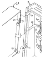
[
FIG. 8 is a view showing a third modification of the mounting structure. In the third modification, unlike the
[0050]
As shown in FIG. 8, the
[0051]
The method of mounting the liquid
[0052]
FIG. 9 shows the relationship between the
[0053]
9, the left side is a front view of the liquid crystal display unit 2C, and the right side is a side view showing a part of the
[0054]
As shown in FIG. 9, the size of the opening facing the
[0055]
Therefore, when viewed from the front of the
[0056]
[Example of card unit connection]
FIG. 10 is a diagram showing an internal structure of the slot machine when a
[0057]
Therefore, medals, which are examples of game media, are not used in games. As shown in the figure, the
[0058]
Referring to FIG. 10, a
[0059]
[Description of display unit]
Next, various display units displayed on the screen of the slot machine described with reference to FIG. 1 and FIGS. 2 to 10 will be described in detail with reference to FIG.
[0060]
Each of the
[0061]
The
[0062]
The
[0063]
The
[0064]
The
[0065]
In the
[0066]
The
[0067]
The number-of-
[0068]
[Explanation of operation unit]
Next, various operation units provided on the
[0069]
The
[0070]
The
[0071]
The
[0072]
Each of the
[0073]
[Game description]
Next, an outline of a game provided by the
[0074]
To start the game, first set the bet amount. The bet amount can be set to one of 1 to 3 by pressing the
[0075]
Pressing the
[0076]
It is also possible to set the number of bets by directly inserting medals into the
[0077]
When playing a game using the card-type slot machine shown in FIG. 10, first, a "debit button" provided in place of the
[0078]
In the
[0079]
After the symbol changing speed on the variable display unit reaches a certain speed, the operation of each of the
[0080]
In the following description, among the
[0081]
When the player presses any one of the
[0082]
On the other hand, when the player does not operate the
[0083]
When the symbols are stopped on all the
[0084]
When a combination of symbols on the activated line has a predetermined specific display mode and a winning has occurred, the game effect lamps 36a and 36b blink in a predetermined mode and a sound effect is output from the
[0085]
In addition, when the display result of the
[0086]
For example, when a big bonus prize is generated, the number of times the big bonus game can be played (for example, up to 30 times) is displayed on the number-of-
[0087]
In the regular bonus state, usually, before reaching the maximum number of continuous games (for example, 12) in which the regular bonus game can be played, the number of winning games is reduced to a specified number (for example, 8) which is an end condition of the regular bonus state. Times) in most cases. For this reason, when a regular bonus prize is generated, the number-of-
[0088]
[Description of control circuit]
FIG. 11 is a block diagram for explaining the configuration of the game control board and the display control board provided in the
[0089]
Of the boards provided in the
[0090]
The
[0091]
Of the switches wired and connected to the
[0092]
The
[0093]
The
[0094]
The
[0095]
Referring to FIG. 12, a
[0096]
The
[0097]
The I /
[0098]
[0099]
The
[0100]
[Description of pull-in control]
Next, "pull-in control" for stopping symbols will be described. As shown in FIG. 11, the detection signal of the
[0101]
In this slot machine, a lottery for winning or non-winning is performed for each winning combination for each game. A random number for winning determination used for the lottery is determined by a control program executed by the
[0102]
The
[0103]
For example, in the case of the
[0104]
In determining which of the five symbols including the symbol at the reference position to stop, the internal winning status is referred to. For example, if the five symbols include a symbol corresponding to the internally won winning combination, a symbol to be stopped at the reference position is selected so that the symbol is preferentially aligned with the activated line. You. Also, for example, when reach is established with a combination of symbols of a winning combination that has not been internally won on valid winning lines of two variable display units that have already finished changing, even if a stop operation is performed. Even when the symbol displayed on the variable display section corresponding to the stop operation at the time of detection is located on the reach line, a symbol that is stopped at the reference position so that other symbols are stopped on the reach line. Is selected.
[0105]
As described above, the state of the symbol on the variable display unit at the time when the stop operation is detected and the internal winning state are determined, and the control for drawing in the symbol corresponding to the winning combination that has been internally won is performed. Control for pulling in symbols other than the symbol corresponding to the winning combination so that no winning combination for the winning combination does not occur is referred to as “pull-in control”. The reference position described above is not limited to the upper stage of the variable display unit, but may be set at the middle stage or the lower stage.
[0106]
In order to generate a prize, the player performs an operation of stopping the fluctuation of the symbol at a proper timing so that the desired symbol stops at the desired prize line. Such an operation is particularly referred to as a “push operation”. For example, in a game in which a winning flag is set, the variable display section is controlled to be drawn in so as to draw a winning combination corresponding to the winning flag. It is possible to generate a prize. However, in a game in which the winning flag is not set, the variable display portion is controlled so as to draw in a symbol other than the winning symbol.
[0107]
Further, even in the game in which the winning flag is set, if the timing of the “pushing operation” is bad, the symbol corresponding to the winning combination may not be able to be drawn even by the pull-in control. As described above, if a winning corresponding to the winning flag cannot be generated even though the winning flag is set, the winning flag is cleared. However, the winning flag of the big bonus prize is different from the winning flag of the other winning combinations, and even if no prize is generated in the game in which the winning flag is set, the winning flag corresponding to the winning flag is set. Until the event occurs, the winning flag is carried over to the next and subsequent games.
[0108]
[Description of symbol array]
FIG. 13 is a diagram showing an array of symbols (also referred to as identification information or symbol marks) variably displayed on each of the left
[0109]
For example, in the case of the left
[0110]
On each of the
[0111]
[Explanation of winning combinations]
Next, the winning combination will be described. As the winning combination, a big bonus, a small combination, a replay, a regular bonus, and a JAC combination are defined.
[0112]
(1) “Big Bonus” is a winning combination in which a privilege that allows the player to play the Big Bonus game a plurality of times is given. Big bonus winning occurs when the stop result of the variable display section is a combination of “no
[0113]
When a regular bonus prize is generated in the big bonus game, the regular bonus game is provided a plurality of times, and after the regular bonus game is consumed, the remaining big bonus games are provided again. The big bonus game is provided until a regular bonus prize is generated a predetermined number of times or a predetermined upper limit number of big bonus games is exhausted, whichever is earlier. In the present embodiment, the state where the regular bonus game is provided is referred to as a “big bonus state”.
[0114]
(2) “Regular bonus” is a winning combination in which a privilege that allows the regular bonus game to be played a plurality of times is provided. The regular bonus prize is generated when the stop result of the variable display unit is a combination of “JAC, JAC, JAC”. In the case of this embodiment, the regular bonus winning can occur only during the big bonus game. In the regular bonus game, only the JAC combination, which is a special winning combination during the regular bonus game, is activated, and the winning combination is internally won with a very high probability. In addition, only one of the five pay lines is valid, and the game can be easily performed, and the game can be completed with one bet. Further, for example, when a winning combination of the JAC combination is won, the maximum value (for example, equivalent to 15 medals) that is allowed to be obtained in one game is given. The regular bonus game is provided continuously until a predetermined number of winnings occurs or a predetermined upper limit number of games is exhausted, whichever is earlier. Since the winning symbol of the JAC role is "JAC", winning during the regular bonus game is particularly called "JAC winning".
[0115]
(3) “Small role” is a prize-winning role that involves only giving a value (for example, credit or medal) without generating a special game such as a big bonus game or a regular bonus game, or a replay game. It is.
[0116]
In the
[0117]
The combination of the symbols of the
The combination of the symbols of the
[0118]
“Stop order small role” includes “left, right, middle”, “middle, left, right”, “middle, right, left” Six types of "right, left, middle" and "right, middle, left" are defined. Then, an internal winning flag is prepared for each pressing order.
[0119]
The combination of the symbols of the
[0120]
(4) “Replay” is a winning combination that gives a privilege that the next game can be started without consuming medals or credits. When a replay winning occurs, the operation of the
[0121]
(5) Further, the JAC combination that is valid only in the regular bonus game is “15 small combination” in which the number of paid out medals is 15.
[0122]
[Description of command]
FIG. 14 is a diagram for explaining an example of a command transmitted from the
[0123]
Each command is composed of, for example, 2-byte data including a header, data indicating a command type, and information part data. In the figure, “brackets” below a command name indicate information part data included in the command. For example, in the case of the start screen layout command, it is indicated that the information section data includes a total of three types of data of the layout of the start screen, the presence / absence of notification, and the winning combination to be notified.
[0124]
In the figure, a command whose command name is shown at the lower left of the arrow (→) is an essential command that is always transmitted during one game. On the other hand, a command whose command name is indicated at the lower right of the arrow is a selective command that may or may not be transmitted during one game.
[0125]
During one game, the commands are transmitted to the
[0126]
The start screen layout command is a command for specifying a layout of a screen displayed when the game is started by operating the
[0127]
The start screen layout command includes, in addition to data for specifying a screen type (layout of each display unit), information on presence / absence of notification and information part data of a winning combination to be notified. These two data are data indicating whether or not to notify the internal winning at the start of the game on the screen of the designated type, and a winning combination to be notified when the internal winning is notified.
[0128]
However, in this embodiment, for simplicity, a case where the winning combination to be notified on the start screen is only the big bonus has been described. Also, as will be described later with reference to FIG. 33, the correspondence between the layout of the start screen and the presence / absence of notification is "normal layout: no notification", "notification layout: notification", and "all character notification layout: notification". In the following, an example in which “presence / absence of notification (big bonus winning notification)” is determined by the type of “start screen layout” will be described.
[0129]
It should be noted that the start screen layout command is also used to give a so-called “gutter” notification. In other words, the
[0130]
The variable display section enlargement command is a command for instructing that the variable display section be enlarged to fill the screen. In this embodiment, for example, it is transmitted when the game in which the big bonus winning flag is carried over is started. In other words, in the game in which the big bonus is internally won, when the big bonus does not occur, the game is transmitted at the start of the subsequent game until the big bonus occurs. Therefore, by changing the screen at the start of the game according to this command, the player is notified that the big bonus has been won. Therefore, the reliability of the notification on this screen is 100%.
[0131]
In the following description, the screen layout (one type: FIG. 32D) displayed at the start of the game according to the variable display section enlargement command, and the screen layout displayed at the start of the game according to the start screen layout command described above. The layouts (three types: FIGS. 32A, 32B, and 32C) are collectively referred to as “start screen layout” or “start screen layout”.
[0132]
The variable display section enlargement command is transmitted when the symbol is stopped at any two of the
[0133]
The change start command is a command for instructing to start changing the symbol in the
[0134]
The eye-catching symbol command is a command for instructing to notify the symbol to be eye-catching, in other words, the symbol of the internally won winning combination. The eye-catching design command includes data indicating [the symbol to be eye-catching]. This push command is transmitted based on the fact that the
[0135]
The
[0136]
The first to third stop order commands are "operation order of
[0137]
The
[0138]
The first to third stop order commands are not always transmitted when the pressing order winning combination is internally won, but each time the pressing order winning combination is internally won, it is determined whether or not to transmit these commands. Is determined by the
[0139]
The first stop order command is transmitted when the three variable display units are changing. The second stop order command is transmitted when one variable display unit is stopped and two variable display units are changing. The third stop order command is transmitted when two variable display units are stopped and one variable display unit is changing.
[0140]
The first to third stop commands are commands for instructing the variable display unit to stop changing. Each command includes information of [variable display section for stopping fluctuation] and [symbol stop position]. In addition, the information of [symbol stop position] includes, for example, a symbol number to be displayed in the upper stage among the upper, middle, and lower symbol display positions of the variable display unit. The
[0141]
[Explanation of flowchart]
FIGS. 15 to 18 are flowcharts for explaining the outline of the processing executed by the
[0142]
Next, a lottery process is executed on condition that a start operation (operation of the start lever 42) is detected (S2: YES) (S3). In the lottery process, it is determined whether or not a winning is allowed and which winning combination is allowed. More specifically, a random number is extracted at the timing when the start operation is detected, and the winning determination table corresponding to the bet amount is compared with the extracted random number. In the winning determination table, the winning value is stored for each winning role (big bonus, regular bonus, small role, replay, JAC role), and whether the extracted random number matches any of the winning values is determined. It is determined, and the presence or absence of the winning is determined.
[0143]
Next, when a winning is made in the lottery process, a winning flag corresponding to the winning combination (the big bonus, the regular bonus, the small winning combination including the stop small, the replay, the JAC winning) is set. (S4).
[0144]
Next, it is determined whether the big bonus carryover flag is ON (S5). The big bonus carry-over flag is a flag that is turned on when the big bonus has not been generated in the game even though the big bonus has been won in the lottery process in S3. Therefore, the fact that the big bonus carryover flag is set means that the big bonus has been won in the previous game but the big bonus has not yet occurred and the big bonus win flag has been carried over.
[0145]
When it is determined in S5 that the big bonus carryover flag is ON, a variable display section enlargement command is set (S7). As a result, the start screen layout displayed based on the detection of the start operation is determined to be the “all variable display section layout” in which the variable display section is enlarged and displayed on the entire surface.
[0146]
When it is determined that the big bonus carry flag is not ON, a random number for start screen selection is extracted (S6). The start screen selection random number is a random number used to determine the type of start screen layout to be displayed based on detection of a start operation. This random number is a soft random number generated by a control program executed by the
[0147]
Next, it is determined whether or not the winning flag is set (S8). When a winning flag is set for any of the winning combinations, it is determined whether or not to notify the eye-catching symbol (S9). In S9, a predetermined random number for determination is extracted, and based on the value of the random number, the presence / absence of notification of the eye-catching symbol is randomly determined.
[0148]
Here, when it is determined that there is a notification, a winning symbol corresponding to the winning combination of the set winning flag is notified in a predetermined manner on the display screen. This aspect will be described later with reference to FIGS.
[0149]
After S9, it is determined whether or not the stop order small win has been won, that is, whether or not the winning flag corresponding to the stop order small win has been set (S10). When the winning flag corresponding to the small stop order is set, it is determined whether or not the stop order is notified (S11). In S11, a predetermined random number for determination is extracted, and based on the value of the random number, the presence or absence of the notification of the stop order small combination is randomly determined.
[0150]
Here, when it is determined that the notification is made, the stop order of the stop order small combination in which the winning flag is set is notified in a predetermined manner on the display screen. This aspect will be described later with reference to FIGS.
[0151]
Next, it is determined whether or not the big bonus winning flag is set, that is, whether or not the occurrence of the big bonus winning in this game is allowed (S12).
[0152]
When the big bonus winning flag is set, the table corresponding to the presence of the winning flag is referred to. Then, a start screen layout associated with the start screen selection random number extracted in S6 is selected from the table (S12).
[0153]
On the other hand, when it is determined in S12 that the big bonus winning flag is not set, and when it is determined in S8 that no winning flag is set, the table corresponding to no winning flag is referred to and the table is referred to. The start screen layout associated with the start screen selection random number extracted in S6 is selected from the above (S14).
[0154]
The relationship between the tables referred to in S12 and S14 and the start screen selection random numbers will be described later with reference to FIG.
[0155]
Next, it is determined whether or not the variable display section enlargement command is set (S21). In this embodiment, a variable display section enlargement command or a start screen layout command is always set for each game.
[0156]
When the variable display section enlargement command is set, the set variable display section enlargement command (set in S7) is transmitted to the display control microcomputer 201 (S22). The
[0157]
On the other hand, when the variable display section enlargement command is not set, a start screen layout command is transmitted to the display control microcomputer 201 (S21). This command includes information on the layout type of the start screen determined in S13 or S14, and information on the winning combination (big bonus in this embodiment) to be notified. The
[0158]
Next, a change start command is transmitted (S24). The
[0159]
Next, it is determined whether or not the announcement of the eye-catching symbol (symbol navigation) is determined (S25). In S9, when it is determined to notify the push symbol, a push symbol command corresponding to the determination in S9 is transmitted (S26).
[0160]
The push symbol command includes information indicating a symbol to be pushed. The
[0161]
Next, it is determined whether or not the stop order has been determined (S27). If it is determined in S11 that the stop order should be announced (stop order navigation), a first stop order command is transmitted (S28). The first stop order command includes information indicating the first stop variable display unit to be stopped first among the plurality of variable display units. The
[0162]
After the process of S28 or after NO is determined in S27, it is determined whether the stop operation invalid period has elapsed (S29). The stop operation invalid period is a period from the start of the simultaneous fluctuation of the symbols on the
[0163]
When it is determined that the stop operation invalid period has elapsed, it is determined whether the first stop operation has been detected (S30). If the first stop operation has not been detected yet, it is determined whether or not the operation waiting time has elapsed (S31).
[0164]
In this embodiment, the stop buttons 41L, 41C, and the stop operation are not detected even if a predetermined "operation waiting time" is counted after the simultaneous change of symbols on the
[0165]
When the first stop operation for stopping the first variable display unit before the operation waiting time elapses, a stop position determination process is executed (S32). In this stop position determination processing, the above-described “pull-in control” is executed for the variable display unit corresponding to the first stop operation, and the first stop is performed according to the change position of the symbol on the variable display unit and the internal winning state. The type of symbol to be stopped on the variable display unit corresponding to the operation is determined.
[0166]
The symbol position determined in the stop position determination processing of S32 is transmitted as a first stop command (S33). The
[0167]
Thereafter, the processing of “S41, S42, S43 to S46” is executed in order to instruct the display control corresponding to the second stop for stopping one of the remaining two variable display units during the change. This process is the same as “S27, S28, S30-S33” described above, except that the target variable display unit is different, and thus the description will not be repeated.
[0168]
Next, the processing of “S47, S48, S49 to S51” is executed in order to instruct display control corresponding to the third stop for stopping the last variable display unit that is changing. This process is the same as “S27, S28, S30-S32” described above, except that the target variable display unit is different, and thus the description will not be repeated.
[0169]
However, in the third stop, it is effective to stop the symbol at the determined symbol stop position before the symbol stop position determined by the stop position determination process executed in S51 is transmitted as the third stop command. It is determined whether or not the combination of the symbols "stop order small combination" will be aligned on the line (S52).
[0170]
When the combination of the symbols of "stop order small combination" is not prepared, the symbol stop position determined in S51 is transmitted as the third stop command (S54).
[0171]
On the other hand, in S52, when it is determined that the combination of the symbols of "stop order small combination" is completed, it is determined whether the combination of the symbol and the "stop order small combination" corresponding to the pressing order match the internal winning content. It is determined (S53), and when it is determined that they do not match, the stop position determination process is executed again in S51, and another symbol stop position is selected. On the other hand, when they match, the symbol stop position determined in S51 is transmitted as the third stop command (S54).
[0172]
Next, a winning determination process is executed (S61). This winning determination process is a process of determining whether or not a winning has occurred based on a stop symbol. Next, a payout process is executed (S62), and a process of paying out medals or credits according to the winning determination by the winning determination process is performed.
[0173]
Next, it is determined whether or not a big bonus prize has occurred (S63). When it is determined that a big bonus prize has occurred, if the big bonus carry flag is set (YES in S64), the big bonus carry flag is turned off (S65), and all the information including the big bonus winning flag is set. Is turned off (S66). If YES in S64, that is, it means that the big bonus generated this time is due to the big bonus winning flag set before the previous game.
[0174]
When it is determined in S63 that the big bonus prize has not occurred, it is determined whether or not the big bonus winning flag is ON (S67). Here, when it is determined to be YES, that is, the big bonus winning does not occur in the game in which the big bonus winning flag is set. In this case, on condition that the big bonus carry-over flag is OFF (S68: YES), the big bonus carry-over flag is turned ON (S69).
[0175]
Note that the case of NO in S68 is a case where the big bonus carryover flag is already ON in the game before the current game. When the big bonus carry flag is ON, it means that the big bonus win flag is carried over to the next game. After S69 (or after NO is determined in S68), the big bonus win flag is left. All winning flags are turned off (S70). Thereafter, the procedure returns to the top of FIG.
[0176]
19 to 21 are flowcharts for explaining the game display processing executed by the
[0177]
In the game display process, after one game is started, first, it is determined whether or not a start screen layout command has been received (SUB1). If the start screen layout command has not been transmitted, it is determined whether or not the variable display section enlargement command has been received (SUB11). Then, both determinations are repeatedly executed until the reception of one of the commands is confirmed.
[0178]
In SUB11, when it is determined that the variable display section enlargement command has been received, switching control for enlarging and displaying the variable display section on the entire screen is executed (SUB12). As a result, the layout of the display screen is changed from the normal layout before the game starts (see FIG. 1) to the “entire variable display section layout” (see FIG. 32D). As described above, when the big bonus winning flag is carried over, the screen is displayed on the entire variable display layout, thereby notifying the player that the big bonus has been won. . Note that the data of the entire variable display section layout is stored in a screen table configured in the
[0179]
Next, on the condition that it is determined that the fluctuation start command has been received (YES in SUB13), control for simultaneously starting the fluctuation of the symbols in the enlarged and displayed
[0180]
On the other hand, when it is determined in SUB1 that a start screen layout command has been received, a process of selecting a layout of the start screen corresponding to the start screen layout command from the screen table is executed (SUB2). The screen table is stored in the
[0181]
Next, a process of switching the image on the
[0182]
Next, it is determined whether or not the selected start screen is a screen with a notice (SUB4). If the selected start screen is a screen with a notice, a notice effect is started in a mode corresponding to the start screen ( SUB5). The start screens with the notice are (B) and (C) in FIGS. 32 (A), (B) and (C).
[0183]
Next, it is determined whether a fluctuation start command has been received (SUB6). When the change start command is received, the change of the symbol is started in each variable display section, and the type of the start screen layout is a “full character notification layout” in which a notification character is displayed on the entire display screen (see FIG. 32C). In the case of, it is necessary to display the
[0184]
Therefore, in SUB7, it is first determined whether or not the start screen layout is the “all character notification layout”. Then, in the case of the "full character notification layout", after the predetermined start screen display time elapses as the time for performing the notification effect (YES in SUB9), the layout of the start screen is returned to the normal layout of FIG. Simultaneous change of symbols is started on the
[0185]
On the other hand, when it is determined in SUB7 that the start screen is not the “full-screen character notification layout”, the simultaneous change of symbols is immediately started in each variable display section (SUB8). In this case, for example, while the predetermined notification effect is displayed on the
[0186]
In SUB10, after the display screen is switched back to the normal layout (see FIG. 1) (when the start screen is in the normal layout, the layout does not change before and after switching), it is determined whether or not the eye-catching symbol command has been received. (SUB21).
[0187]
When the eye-catching symbol command is received, display control for notifying the eye-catching symbol in a predetermined manner is executed according to the command (SUB22). In addition, the specific example of the alerting | reporting aspect of the press design is mentioned later using FIGS.
[0188]
Next, it is determined whether or not the first stop order command has been received (SUB23). Then, when the first stop order command is received, display control for notifying the stop order is executed according to the command (SUB24). A specific example of the notification mode of the stop order will be described later with reference to FIGS.
[0189]
Next, the process waits for reception of the first stop command (SUB25), and executes a process of stopping and displaying the symbol specified by the command on the variable display unit corresponding to the received first stop command (SUB26).
[0190]
Next, it is determined whether or not the second stop order command has been received (SUB27). Then, when the second stop order command is received, display control for notifying the stop order is executed according to the command (SUB28).
[0191]
Next, the process waits for reception of the second stop command (SUB29), and executes a process of stopping and displaying the symbol designated by the command on the variable display unit corresponding to the received second stop command (SUB30).
[0192]
Next, it is determined whether or not the third stop order command has been received (SUB41). Then, when the third stop order command is received, display control for notifying the stop order is executed according to the command (SUB42).
[0193]
Next, the process waits for the reception of the third stop command (SUB43), and executes a process of stopping and displaying the symbol specified by the command on the variable display unit corresponding to the received third stop command (SUB44). By executing this process, the symbols are stopped and displayed on all the variable display units.
[0194]
Next, it is determined whether or not the screen is other than the normal layout (SUB45). When the screen is not the normal layout, YES is determined in this SUB45, and control for switching the screen layout to the normal layout is executed (SUB46). The game display processing ends. By the
[0195]
[Display example of push order navigation]
Next, a specific display example of the push order navigation will be described with reference to FIGS. FIGS. 22 to 25 show display examples in which the pressing order of the internally pressed winning small pressing combination is notified by changing the images of the
[0196]
FIG. 22 is a diagram showing a display pattern in which the variable display section in which the stop order has arrived is displayed in an enlarged manner and the variable display section in which the stop order has not arrived is displayed in a reduced size to notify the pressing order.
[0197]
In this enlargement / reduction pattern, after the simultaneous change of symbols in each variable display section is started in the normal layout (see FIG. 1), first, only the middle
[0198]
After the middle
[0199]
After the left
[0200]
Thereafter, when a stop operation of the right
[0201]
FIG. 23 is a diagram showing a display pattern for notifying the pressing order by extending the variable display unit in which the stopping order has arrived in the scroll direction.
[0202]
In the expansion pattern shown in FIG. 23, only the variable display section in which the stop order has arrived is expanded in the scroll direction. Therefore, similarly to the display pattern of FIG. 22, there is an advantage that the player can easily perform the eye pressing operation. is there. In the expansion pattern shown in FIG. 23 as well, the variable display section that has reached the stop order changes in the order of (A), (B), (C), and (D), and the stop order is notified to the player. In the expansion pattern of FIG. 23, the variable display section in which the stop order has not arrived and the variable display section in which the symbols have already been stopped and displayed are not reduced in size.
[0203]
FIG. 24 is a diagram illustrating a display pattern in which the pressing order is notified by shielding the variable display units other than the variable display unit in which the stop order has arrived among the variable display units during the variable display with the shielding (hidden)
[0204]
In the shielding pattern shown in FIG. 24, the order changes in the order of (A), (B), (C), and (D), and the stop order has arrived among the variable display portions in which the symbols are variably displayed. Parts other than the variable display section are shielded by the
[0205]
FIG. 25 is a diagram showing a display pattern for notifying the pressing order by displaying a semi-transparent display of the variable display portions whose symbols are fluctuating, except for the variable display portions in the stop order.
[0206]
In FIG. 25, the symbol indicated by a broken line is a symbol displayed translucently. In the translucent pattern shown in FIG. 25, the variable display portions change in the order of (A), (B), (C), and (D), and among the variable display portions in which symbols are variably displayed, the variable order in which the stop order has arrived. Parts other than the display are translucently displayed. Instead of making the symbol translucent, the symbol may be completely removed from the variable display unit. Alternatively, instead of translucent the design in which the stop order has not arrived, the color (brightness, saturation, color tone) of the design in which the stop order has arrived and the color of the design in which the stop order has not arrived You may make it different.
[0207]
As the push order navigation of the
[0208]
As described above, in the slot machine according to the present embodiment, by changing the images of the
[0209]
[Display example of eye-catching navigation]
Next, a specific display example of the eye-catching navigation will be described with reference to FIGS. FIGS. 26 to 30 show display examples of notifying the eye-catching symbol by changing the images of the
[0210]
In any of FIGS. 26 to 30, the case where the push symbol of the notification target is “bell” and the order in which the change of the symbol of the variable display unit stops is “left → center → right” is exemplified. ing. In each of FIGS. 26 to 30, (A) is a display mode example before the first stop operation, (B) is a display mode example before the second stop operation, and (C) is a third display mode. It is an example of a display mode before a stop operation, and (D) is an example of a display mode when a symbol stops on all the variable display units.
[0211]
FIG. 26 is a diagram showing a display pattern in which the eye-catching symbol is enlarged and the other symbols are reduced. In this enlargement / reduction pattern, after the symbols start to fluctuate simultaneously in the
[0212]
Thereafter, when the first stop operation (the left variable display unit) is detected, the change of the symbol on the variable display unit corresponding to the first stop operation is stopped. At this time, as shown in (B), the size of the symbol displayed on the variable display portion where the symbol has stopped returns to the original size. Hereinafter, in the same manner, in response to the detection of the second stop operation and the third stop operation, as shown in (C) and (D), the change of the symbol is stopped at the corresponding variable display section.
[0213]
By such a change in the display mode, the player can recognize the target to be pushed. In addition, since the design to be pushed is enlarged and the other designs are displayed in a reduced size, the design to be pushed is conspicuous and the pushing operation becomes easier.
[0214]
FIG. 27 is a diagram showing a display pattern in which only the eye-catching symbol is enlarged and the display size of other symbols is not changed. This enlarged pattern is different from the enlarged / reduced pattern shown in FIG. 26 in that the display size is not changed except for the design to be pushed.
[0215]
FIG. 28 is a diagram showing a display pattern for shielding a symbol other than the eye-catching symbol. In this shielding pattern, after the symbols start to fluctuate simultaneously in the
[0216]
Thereafter, when the first stop operation (the left variable display unit) is detected, the change of the symbol on the variable display unit corresponding to the first stop operation is stopped. At this time, as shown in (B), the shielded
[0219]
By such a change in the display mode, the player can recognize the target to be pushed. In addition, since the pattern other than the design to be pushed is shielded, the design to be pushed is conspicuous and the pushing operation becomes easier.
[0218]
In FIG. 28, the design is shielded by the
[0219]
FIG. 29 is a diagram showing a display pattern for making a symbol other than the eye-catching symbol translucent. In this translucent pattern, after the symbols start to fluctuate simultaneously in the
[0220]
Thereafter, when the first stop operation (the left variable display unit) is detected, the change of the symbol on the variable display unit corresponding to the first stop operation is stopped. At this time, as shown in (B), the translucent display is not performed on the variable display unit where the symbols are stopped, and all the symbols stopped on the variable display unit are displayed like the bell. Hereinafter, in the same manner, in response to the detection of the second stop operation and the third stop operation, as shown in (C) and (D), the change of the symbol is stopped at the corresponding variable display section, Finally, the display result is derived and displayed in a state where the display is not translucent.
[0221]
Instead of the translucent display, the design to be pushed may be made completely invisible. Alternatively, instead of making the design translucent, the color (brightness, saturation, color tone) of the design to be pushed may be made different from the color of the design not to be pushed.
[0222]
FIG. 30 is a diagram showing a display pattern in which the arrangement pattern of the symbols on the variable display section is changed and the symbols to be pushed are continuously displayed. In the continuous display pattern, the symbol arrangement (referred to as a normal symbol arrangement) of FIG. 13 is used for the variable display section in which the symbol change is stopped, but the variable display section in which the symbol is changing is used as a push notification. The symbol array of FIG. 31 in which symbols as objects (bells in this example) are continuously arranged (referred to as a continuous symbol array) is used.
[0223]
The feature of the continuous symbol arrangement of FIG. 31 is that, although the arrangement position is different, the symbol assigned to each variable display section is not different from the normal symbol arrangement of FIG. For example, regarding the left variable display section, in each of the symbol arrangements of FIGS. 13 and 31, the number of “bells” is 5, the number of “patterned 7” is 1, the number of “no
[0224]
Therefore, it can be said that the continuous symbol array of FIG. 31 is obtained by changing the correspondence between the symbol number and the symbol type for each variable display unit based on the normal symbol array of FIG.
[0225]
In this continuous pattern, when the simultaneous change of the symbols is started, the continuous arrangement shown in FIG. 31 is adopted in all the
[0226]
Thereafter, when the first stop operation (the left variable display unit) is detected, the change of the symbol on the variable display unit corresponding to the first stop operation is stopped. At this time, as shown in (B), the symbols are stopped and displayed in the normal arrangement of FIG. 13 for the variable display section where the symbols are stopped. Hereinafter, in the same manner, in response to the detection of the second stop operation and the third stop operation, as shown in (C) and (D), the change of the symbol is stopped at the corresponding variable display section, Finally, the symbols are stopped and displayed in the normal arrangement on all the variable display sections.
[0227]
As described above, according to the continuous pattern, the player can recognize the push target more easily. When the symbols stop, the symbols may be stopped in the continuous arrangement without returning to the normal arrangement.
[0228]
As the eye-catching navigation of the
[0229]
As described above, in the slot machine according to the present embodiment, by changing the images of the
[0230]
[Specific example of start screen layout]
Next, a start screen layout selectively displayed when the game is started will be described with reference to FIGS. FIG. 32 is a diagram showing a start screen layout. FIG. 33 is a diagram showing the correspondence between the start screen selection random numbers and the screen layout. 32A and 32B, the
[0231]
FIG. 32A shows a start screen according to “normal layout”. In the figure, a downward arrow means that the symbol is changing (scrolling) in that direction (the same applies hereinafter). The start screen of the normal layout is not different from the layout of the
[0232]
FIG. 32 (B) shows a start screen with a “notification layout” for notifying a big bonus. In the “notification layout”, the area of the
[0233]
FIG. 32 (C) shows a start screen based on a “full character notification layout” in which a big bonus is announced in a mode different from FIG. 32 (B). In the “full character notification layout”, the area of the
[0234]
FIG. 32D shows a “full-screen variable display section layout” in which the variable display section is displayed on the full screen. FIGS. 32A to 32C show start screen layouts selectively displayed according to a start screen layout command. On the other hand, the “entire variable display layout” shown in FIG. 32D is a start screen layout displayed according to the variable display enlargement command. As described above, this “full-size variable display section layout” is a layout selected at the start of the game in which the big bonus winning flag has been carried over, and constitutes a big bonus winning notification screen with an expectation of 100%.
[0235]
Next, with reference to FIG. 33, the selection of the layout in FIGS. 32 (A) to 32 (C) will be described. The layouts in FIGS. 32A to 32C are selected based on a predetermined table and a start screen selection random number, as described with reference to S13 and S14 in FIG.
[0236]
FIG. 33A shows the “table corresponding to the presence of the big bonus winning flag” referred to in S13. As shown, the numerical value of the random number for start screen selection is associated with the screen layout. By referring to this table, the “notification layout” is assigned to the “notification layout”, and the “all-characters notification layout” is assigned to the “notification layout”. It can be understood that the number of random numbers is large.
[0237]
FIG. 33 (2) shows the “table corresponding to no big bonus winning flag” referred to in S14. As shown, the numerical value of the random number for start screen selection is associated with the screen layout. By referring to this table, the “notification layout” is assigned to the “notification layout”, and the “all-characters notification layout” is assigned to the “notification layout”. It can be understood that the number of random numbers is small.
[0238]
Based on the table configurations of FIGS. 33 (1) and (2), of the “notification layout (FIG. 32 (B))” for notifying the big bonus and the “all character notification layout (FIG. 32 (C))”. When the big bonus winning flag is set (ON), the selection ratio that is high is “full character notification layout”. In other words, as shown in FIG. 33 (3), when the big bonus winning is announced by the “full character announcement layout”, the big bonus winning is announced by the “announcement layout”. This means that the reliability of the announcement is high.
[0239]
As described above, in the slot machine according to the present embodiment, the layout of the
[0240]
In addition, as a mode of the notification of the big bonus winning using the notification character, a plurality of types of notification layouts (notification layout (FIG. 32 (B))) and “all character notification layout (FIG. 32 (C))” are provided. Pattern) is prepared, so that various effects can be produced. Moreover, since the reliability of the notification differs depending on the type of the notification layout, the interest in the notification effect increases. Furthermore, since the powerful notification layout using the full screen has a higher expectation of the notification than the notification layout using a part of the screen, the mode of the notification is associated with the higher degree of the expectation. Therefore, it is possible to make a notification effect that is easy for the player to understand.
[0241]
As the notification patterns, two types using notification characters are illustrated, but three or more types of notification patterns may be prepared. In this case, it is desirable that the larger the size of the
[0242]
Further, in this embodiment, according to the start screen layout command, “notification layout (FIG. 32 (B))” and “full-page character notification layout (FIG. 32 (C))” including the effect by the notification character.
In the above embodiment, as shown in FIG. 33, one of “normal layout”, “notification layout”, and “all-characters notification layout” is selected according to the random number for start screen selection. However, the “full character display layout” may be replaced with the “full variable display layout” in FIG.
[0243]
In this case, when it is determined in S12 of the flowchart of FIG. 15 that the big bonus winning flag is set, in S13, based on the table shown in FIG. ) Is selected. Therefore, the “all-area variable display section layout” becomes a notification pattern with high expectation (although not 100%). It should be noted that, when the replacement is performed in this manner, the “full screen variable display section layout” in FIG. 32D is designated by the start screen layout command shown in FIG. In this way, in the replacement, the function of separately executing the processing shown in S5 and S7 in FIG. 15 and setting the variable display section enlargement command may be left, or alternatively, the function may be replaced in S5 and S7. The indicated process may be deleted.
[0244]
Next, modifications and features of the embodiment of the invention described above are listed below.
[0245]
(1) The
[0246]
(A1) An image display unit having a display screen for displaying a plurality of variable display units (
[0247]
According to the above configuration, it is possible to emphasize the display content of any one of the plurality of variable display units or the effect display unit, whereby the effect display unit and the variable display are displayed in a more effective effect. It is possible to provide a slot machine that can change the arrangement pattern with the units.
[0248]
(A2) An image display unit having a display screen that displays images of a plurality of variable display units (
[0249]
According to the above configuration, when the arrangement pattern is changed to a specific screen arrangement pattern, it is notified that the expected degree of winning is high, and thereby, the effect is more enhanced. A slot machine in which the arrangement pattern of the effect display unit and the variable display unit can be changed can be provided.
[0250]
(A3) In the specific arrangement pattern, a character determined in advance corresponding to a winning combination symbol that needs to be derived and displayed on the variable display unit in order to generate a winning by a winning combination allowed to generate a winning is generated. This is a pattern displayed on the entire display screen (FIG. 32C).
[0251]
According to the above configuration, it is possible to emphasize and notify by a character displayed on the entire surface that the expected degree of occurrence of winning is high.
[0252]
(A4) The slot machine includes a front frame unit including the plurality of operation units (the
[0253]
According to the above configuration, since the lower part of the housing is covered by the front frame unit and the upper part of the housing is covered by the image display unit, a game having a powerful visual effect in a large image display area. Can be provided. Further, since the image display unit and the front frame unit can be exchanged independently of each other, the maintainability can be improved. Further, only the image display unit can be reused for another model.
[0254]
(A5) The slot machine includes the plurality of operation units, and has a front frame unit (the
[0255]
According to the above-described configuration, the screen frame portion at the top of the slot machine can be secured as an area of the screen while leaving the screen frame portion at the top of the slot machine, so a powerful visual effect in a large image display area. Can provide excellent games. Further, since the frame member of the image display unit is hidden behind the opening, the design of the image display unit is not impaired by exposing the frame member of the image display unit when viewed from the front of the slot machine.
[0256]
(B1) The
[0257]
According to the above configuration, since the lower part of the housing is covered by the front frame unit and the upper part of the housing is covered by the image display unit, a game having a powerful visual effect in a large image display area. Can be provided. Further, since the image display unit and the front frame unit can be exchanged independently of each other, the maintainability can be improved. Further, only the image display unit can be reused for another model.
[0258]
(B2) The housing includes a mounting portion (guide rail 4c of the
[0259]
According to the above configuration, it is possible to provide a slot machine that can easily attach the image display unit to the housing.
[0260]
(B3) The image display unit is attached to the housing so as to be openable and closable (attachment of the liquid
[0261]
According to the above configuration, since the image display unit can be freely opened and closed with respect to the housing, the maintainability can be further improved.
[0262]
(B4) The screen frame is a decorative frame with a decoration (FIG. 9:
[0263]
According to the above configuration, the decorativeness of the slot machine can be improved.
(C1) The
[0264]
According to the above configuration, when a prize for a special prize combination is permitted, the operation order of the plurality of operation units determined to the prize combination is notified by using the variable display unit. In addition, the notification of the operation order can be easily understood by the player.
[0265]
(C2) The notifying unit notifies the operating unit in which the operation order has arrived by enlarging and displaying the variable display unit corresponding to the operation unit in which the operation order has arrived (FIGS. 22 and 23).
[0266]
According to the above configuration, the variable display unit corresponding to the operation unit in which the operation order has arrived is conspicuous, so that the notification of the operation order can be performed even more easily for the player. In addition, the player can easily perform the eye-pressing operation.
[0267]
(C3) The notification means enlarges the variable display section corresponding to the operation section in which the operation order has arrived, and displays the variable display section corresponding to the operation section in which the operation order has not arrived in a reduced size, thereby displaying the operation order. Is notified (FIG. 22).
[0268]
According to the above configuration, the variable display unit corresponding to the operation unit in which the operation order has arrived stands out in relation to the other variable display units, so that the notification of the operation order can be performed even more easily for the player. it can. In addition, the player can easily perform the eye-pressing operation.
[0269]
(C4) The notification unit notifies the operation unit that the operation order has arrived by blocking the variable display units other than the variable display unit corresponding to the operation unit that the operation order has arrived (FIG. 24).
[0270]
According to the above configuration, the variable display unit corresponding to the operation unit in which the operation order has arrived stands out in relation to the other variable display units, so that the notification of the operation order can be performed even more easily for the player. it can.
[0271]
(C5) The notification unit changes the color of the variable display unit corresponding to the operation unit in which the operation order has arrived and the color of the variable display unit corresponding to the operation unit in which the operation order has not arrived. The operation unit that has arrived is notified (FIG. 25).
[0272]
According to the above configuration, the variable display unit corresponding to the operation unit in which the operation order has arrived stands out in relation to the other variable display units, so that the notification of the operation order can be performed even more easily for the player. it can.
[0273]
(D1) An image display unit having a display screen for displaying an image of a plurality of variable display units (
[0274]
According to the above configuration, a winning combination symbol that needs to be derived and displayed on the variable display unit in order to generate a winning for a winning combination for which a winning is allowed is displayed in a variable display mode on the variable display unit. Can be notified more clearly to the player because
(D2) The notifying unit notifies the winning combination symbol by enlarging and displaying the winning combination symbol among the symbols variably displayed on the variable display unit (FIGS. 26 and 27).
[0275]
According to the above configuration, since the winning combination symbols to be pushed are conspicuous, the pushing can be notified more easily to the player. In addition, it becomes easier for the player to concentrate on pushing.
[0276]
(D3) The notifying unit notifies the winning combination symbol by enlarging and displaying the winning combination symbol out of the symbols variably displayed on the variable display unit and displaying the symbol other than the winning combination symbol in a reduced size. (FIG. 26).
[0277]
According to the above configuration, since the winning combination symbols to be pushed are conspicuous, the pushing can be notified more easily to the player. In addition, it becomes easier for the player to concentrate on pushing.
[0278]
(D4) The notifying unit notifies the winning combination symbol by displaying an image concealing a symbol other than the winning combination symbol among the symbols variably displayed on the variable display unit (FIG. 28).
[0279]
According to the above configuration, since the winning combination symbols to be pushed are conspicuous, the pushing can be notified more easily to the player. In addition, it becomes easier for the player to concentrate on pushing.
[0280]
(D5) The notifying unit notifies the winning combination symbol by making the color of the winning combination symbol different from the symbol other than the winning combination symbol among the symbols variably displayed on the variable display section ( (FIG. 29).
[0281]
According to the above configuration, since the winning combination symbols to be pushed are conspicuous, the pushing can be notified more easily to the player. In addition, it becomes easier for the player to concentrate on pushing.
[0282]
(D6) The notifying means notifies the winning combination symbol by variably displaying a plurality of the winning combination symbols continuously on the variable display section (FIG. 30).
[0283]
According to the above configuration, since the winning combination symbols to be pushed are conspicuous, the pushing can be notified more easily to the player. In addition, it becomes easier for the player to concentrate on pushing.
[0284]
(2) A liquid crystal display device has been described as an example of the image display device. However, in place of the liquid crystal display device, a rear projector, a cathode ray tube (CRT) display device, a field emission display (FED), a plasma display panel (PDP), an electro luminescence (EL) display, a display using a fluorescent display, or an LED is used. An apparatus may be employed. Further, the present invention is not limited to such a display device, and may be a dot matrix display or a 7-segment display.
[0285]
(3) The liquid
[0286]
(4) In the
[0287]
(5) A plurality of variable display units for variably displaying a plurality of types of identification information each of which can be identified by the
[0288]
(6) The embodiments disclosed this time should be considered as illustrative in all points and not restrictive. The scope of the present invention is defined by the terms of the claims, rather than the description above, and is intended to include any modifications within the scope and meaning equivalent to the terms of the claims.
[Brief description of the drawings]
FIG. 1 is an overall front view of a slot machine.
FIG. 2 is a perspective view of the slot machine viewed obliquely from the upper right.
FIG. 3 is a side view of the slot machine.
FIG. 4 is a view for explaining the internal structure of the slot machine.
FIG. 5 is a diagram for explaining a structure for attaching a liquid crystal display unit and a front frame unit to a housing.
FIG. 6 is a view for explaining a structure in which a liquid crystal display unit is attached to a housing using an L-shaped pin (Modification 1).
FIG. 7 is a view for explaining a structure in which a liquid crystal display unit is mounted by being guided by a guide rail of a housing (Modification 2).
FIG. 8 is a view for explaining a mounting structure for mounting a liquid crystal display unit from the back side of a front frame unit (Modification 3).
FIG. 9 is a diagram showing the relationship between the screen of the liquid crystal display unit, a frame member surrounding the screen, and the size of an opening formed in the front frame unit.
FIG. 10 is a view showing the internal structure of the slot machine when a card unit is connected.
FIG. 11 is a block diagram illustrating a configuration of a game control board and a display control board.
FIG. 12 is a block diagram illustrating a configuration of a display control board.
FIG. 13 is a diagram for explaining a symbol arrangement.
FIG. 14 is a diagram for explaining various commands transmitted from the game control microcomputer to the display control microcomputer.
FIG. 15 is a flowchart illustrating a processing procedure executed by the game control microcomputer during one game.
FIG. 16 is a flowchart illustrating a processing procedure executed by the game control microcomputer during one game.
FIG. 17 is a flowchart illustrating a processing procedure executed by the game control microcomputer during one game.
FIG. 18 is a flowchart illustrating a processing procedure executed by the game control microcomputer during one game.
FIG. 19 is a flowchart illustrating a processing procedure executed by the display control microcomputer during one game.
FIG. 20 is a flowchart illustrating a processing procedure executed by the display control microcomputer during one game.
FIG. 21 is a flowchart illustrating a processing procedure executed by a display control microcomputer during one game.
FIG. 22 is a diagram for describing a display example of push order navigation.
FIG. 23 is a diagram for describing a display example of push order navigation.
FIG. 24 is a diagram for explaining a display example of push order navigation.
FIG. 25 is a diagram for explaining a display example of push order navigation.
FIG. 26 is a diagram for describing a display example of a push navigation.
FIG. 27 is a diagram for describing a display example of eye-catching navigation.
FIG. 28 is a diagram for describing a display example of eye-catching navigation.
FIG. 29 is a diagram for explaining a display example of the push navigation.
FIG. 30 is a diagram for explaining a display example of the push navigation.
FIG. 31 is a diagram for explaining a symbol arrangement when a push navigation (continuous pattern) is performed.
FIG. 32 is a diagram showing a start screen layout. .
FIG. 33 is a diagram showing a correspondence relationship between a random number for start screen selection and a screen layout.
[Explanation of symbols]
1 slot machine, 2 liquid crystal display unit, 2f frame member, 2w decorative frame, 3 front frame unit, 3f decorative frame, 4 housing, 20 liquid crystal display device, 20w frame member, 21 screen, 22 effect display area, 23L, 23C , 23R variable display section, 41 stop button, 42 start lever, 43 single BET button, 44 MAXBET button, 100 game control board, 101 game control microcomputer, 200 display control board, 201 display control microcomputer.
Claims (7)
前記複数の可変表示部の表示結果を導出表示させる操作を行なうための複数の操作部であって、各可変表示部の表示結果を個別に導出表示させるために各可変表示部に対応して設けられた操作部と、
入賞を許容するか否かを入賞役の種類別に抽選する抽選手段と、
前記複数の操作部のいずれかについての操作が検出された時点で当該操作が検出された操作部に対応する可変表示部に表示されている図柄、および当該図柄以降に表示される順番が到来する所定個数の図柄のうちに、前記抽選手段によって入賞が許容された入賞役に対応する図柄が含まれるときに、当該図柄を前記可変表示部に導出表示させる導出表示位置制御手段と、
前記複数の操作部の操作順が定められた特殊入賞役についての入賞が前記抽選手段により許容されたときに、当該特殊入賞役に定められた操作順で前記複数の操作部が操作されたときのみ当該特殊入賞役に対応する図柄の組合せを導出表示するように制御する規制手段と、
前記抽選手段により、前記特殊入賞役についての入賞が許容されたときに、当該入賞役に定められた前記複数の操作部の操作順を前記可変表示部を用いて報知する報知手段とを含むことを特徴とする、スロットマシン。An image display unit having a display screen for displaying an image of a plurality of variable display portions for repeatedly variably displaying a plurality of types of symbols in a predetermined order, wherein a combination of symbols derived and displayed as a display result of the plurality of variable display portions A slot machine in which a prize is generated according to
A plurality of operation units for performing an operation of deriving and displaying the display results of the plurality of variable display units, provided in correspondence with each of the variable display units to individually derive and display the display results of each of the variable display units. Operation unit,
Lottery means for selecting whether to allow a prize or not according to the type of winning combination,
When an operation on any of the plurality of operation units is detected, the symbol displayed on the variable display unit corresponding to the operation unit where the operation is detected, and the order of display after the symbol arrives. When a predetermined number of symbols include a symbol corresponding to a winning combination permitted to be won by the lottery means, a derived display position control means for causing the variable display unit to derive and display the symbol,
When a prize for the special winning combination in which the operation order of the plurality of operation units is determined is permitted by the lottery means, the plurality of operation units are operated in the operation order determined for the special winning combination. Regulating means for controlling so as to derive and display a combination of symbols corresponding to the special winning combination only;
Notifying means for notifying, using the variable display unit, the order of operation of the plurality of operation units determined for the winning combination when the winning for the special winning combination is permitted by the lottery means. A slot machine.
前記画像表示ユニットを上部に、前記前面枠ユニットを下部にして、各々が着脱自在に取付けられる筐体とをさらに含み、
前記画像表示ユニットと前記前面枠ユニットとで前記筐体の前面が覆われることを特徴とする、請求項1〜請求項5のいずれかに記載のスロットマシン。A front frame unit including the plurality of operation units,
The image display unit in the upper part, the front frame unit in the lower part, further comprising a housing that is each detachably attached,
The slot machine according to any one of claims 1 to 5, wherein a front surface of the housing is covered with the image display unit and the front frame unit.
該前面枠ユニットが開閉自在に取付けられる筐体とをさらに含み、
前記前面枠ユニットは、前記画像表示ユニットの画面を臨ませる開口を形成する画面枠であって、スロットマシンの前面側の上部左隅部から右隅部に向かう方向に延びる枠を含む画面枠を含み、
前記開口のサイズは、前記画像表示ユニットの画面を臨ませたときに前記開口一杯に前記画面が広がり、かつ当該画面を囲む前記画像表示ユニットのフレーム部材部分が隠れる大きさであることを特徴とする、請求項1〜請求項5のいずれかに記載のスロットマシン。With the plurality of operation units, a front frame unit to which the image display unit is attached,
A housing to which the front frame unit is attached to be openable and closable,
The front frame unit includes a screen frame that forms an opening facing the screen of the image display unit and includes a frame extending in a direction from an upper left corner to a right corner on the front side of the slot machine. ,
The size of the opening is such that when the screen of the image display unit is viewed, the screen is widened to fill the opening, and the frame member portion of the image display unit surrounding the screen is hidden. The slot machine according to claim 1, wherein:
Priority Applications (1)
| Application Number | Priority Date | Filing Date | Title |
|---|---|---|---|
| JP2003019095A JP2004229730A (en) | 2003-01-28 | 2003-01-28 | Slot machine |
Applications Claiming Priority (1)
| Application Number | Priority Date | Filing Date | Title |
|---|---|---|---|
| JP2003019095A JP2004229730A (en) | 2003-01-28 | 2003-01-28 | Slot machine |
Publications (1)
| Publication Number | Publication Date |
|---|---|
| JP2004229730A true JP2004229730A (en) | 2004-08-19 |
Family
ID=32949060
Family Applications (1)
| Application Number | Title | Priority Date | Filing Date |
|---|---|---|---|
| JP2003019095A Withdrawn JP2004229730A (en) | 2003-01-28 | 2003-01-28 | Slot machine |
Country Status (1)
| Country | Link |
|---|---|
| JP (1) | JP2004229730A (en) |
Cited By (2)
| Publication number | Priority date | Publication date | Assignee | Title |
|---|---|---|---|---|
| JP2006340810A (en) * | 2005-06-07 | 2006-12-21 | Samii Kk | Spin drum type game machine |
| JP2015109953A (en) * | 2013-10-31 | 2015-06-18 | 株式会社高尾 | Reel type game machine |
-
2003
- 2003-01-28 JP JP2003019095A patent/JP2004229730A/en not_active Withdrawn
Cited By (3)
| Publication number | Priority date | Publication date | Assignee | Title |
|---|---|---|---|---|
| JP2006340810A (en) * | 2005-06-07 | 2006-12-21 | Samii Kk | Spin drum type game machine |
| JP2015109953A (en) * | 2013-10-31 | 2015-06-18 | 株式会社高尾 | Reel type game machine |
| JP2015109949A (en) * | 2013-10-31 | 2015-06-18 | 株式会社高尾 | Reel type game machine |
Similar Documents
| Publication | Publication Date | Title |
|---|---|---|
| JP4854865B2 (en) | Slot machine | |
| US9520017B2 (en) | Gaming device for determining a re-drawing group for following games | |
| JP3983598B2 (en) | Slot machine | |
| US8235813B2 (en) | Gaming machine having auxiliary lighting feature | |
| US7837562B2 (en) | Display panel for a gaming apparatus | |
| US9495843B2 (en) | Gaming machine and method for a bonus game with increasing payout rate | |
| JP2004229738A (en) | Slot machine | |
| US9520019B2 (en) | Gaming machine | |
| JP2004267243A (en) | Game machine | |
| JP2006305182A (en) | Game machine | |
| JP2004208890A (en) | Symbol combination game machine | |
| JP2005334460A (en) | Game machine | |
| JP2002143379A (en) | Game machine | |
| JP2006305183A (en) | Game machine | |
| JP2002346052A (en) | Slot machine | |
| US9092949B2 (en) | Gaming machine and methods of allowing a player to play gaming machines having synchronized symbols | |
| JP2002346133A (en) | Game machine | |
| JP4836745B2 (en) | Slot machine | |
| JP2004229733A (en) | Slot machine | |
| JP2004229731A (en) | Slot machine | |
| JP2004229730A (en) | Slot machine | |
| JP2007325860A (en) | Game machine | |
| JP4650874B2 (en) | Game machine | |
| JP4702909B2 (en) | Medal game machine | |
| JP5116351B2 (en) | Slot machine |
Legal Events
| Date | Code | Title | Description |
|---|---|---|---|
| A300 | Withdrawal of application because of no request for examination |
Free format text: JAPANESE INTERMEDIATE CODE: A300 Effective date: 20060404 |