JP2004153267A - Thermal interface pad having sufficient mechanical flexibility - Google Patents
Thermal interface pad having sufficient mechanical flexibility Download PDFInfo
- Publication number
- JP2004153267A JP2004153267A JP2003359658A JP2003359658A JP2004153267A JP 2004153267 A JP2004153267 A JP 2004153267A JP 2003359658 A JP2003359658 A JP 2003359658A JP 2003359658 A JP2003359658 A JP 2003359658A JP 2004153267 A JP2004153267 A JP 2004153267A
- Authority
- JP
- Japan
- Prior art keywords
- thermal interface
- interface plate
- plate assembly
- thermal
- plates
- Prior art date
- Legal status (The legal status is an assumption and is not a legal conclusion. Google has not performed a legal analysis and makes no representation as to the accuracy of the status listed.)
- Withdrawn
Links
Images


Classifications
-
- F—MECHANICAL ENGINEERING; LIGHTING; HEATING; WEAPONS; BLASTING
- F28—HEAT EXCHANGE IN GENERAL
- F28F—DETAILS OF HEAT-EXCHANGE AND HEAT-TRANSFER APPARATUS, OF GENERAL APPLICATION
- F28F23/00—Features relating to the use of intermediate heat-exchange materials, e.g. selection of compositions
-
- F—MECHANICAL ENGINEERING; LIGHTING; HEATING; WEAPONS; BLASTING
- F28—HEAT EXCHANGE IN GENERAL
- F28F—DETAILS OF HEAT-EXCHANGE AND HEAT-TRANSFER APPARATUS, OF GENERAL APPLICATION
- F28F13/00—Arrangements for modifying heat-transfer, e.g. increasing, decreasing
- F28F2013/005—Thermal joints
-
- Y—GENERAL TAGGING OF NEW TECHNOLOGICAL DEVELOPMENTS; GENERAL TAGGING OF CROSS-SECTIONAL TECHNOLOGIES SPANNING OVER SEVERAL SECTIONS OF THE IPC; TECHNICAL SUBJECTS COVERED BY FORMER USPC CROSS-REFERENCE ART COLLECTIONS [XRACs] AND DIGESTS
- Y10—TECHNICAL SUBJECTS COVERED BY FORMER USPC
- Y10T—TECHNICAL SUBJECTS COVERED BY FORMER US CLASSIFICATION
- Y10T29/00—Metal working
- Y10T29/49—Method of mechanical manufacture
- Y10T29/4935—Heat exchanger or boiler making
Abstract
Description
本発明は、一般に熱伝達の分野に関し、詳細には、熱伝達中の熱接触抵抗の分野に関する。 The present invention relates generally to the field of heat transfer, and in particular, to the field of thermal contact resistance during heat transfer.
近頃の電子機器は、デバイスをより小型化して製造できる能力によって恩恵をこうむってきた。デバイスを小型化できる能力が高まるにつれて、その性能も向上してきた。あいにく、このような性能の向上には、デバイスの電力密度だけでなく、電力の増大もともなうことになる。これらのデバイスの信頼性を維持するために、業界は、このような熱を効率的に除去する新たな方法を見つけ出さなければならない。 Recently, electronics have benefited from the ability to make devices smaller and smaller. As the ability to miniaturize devices has increased, so has its performance. Unfortunately, such performance improvements involve not only the power density of the device, but also its power. To maintain the reliability of these devices, the industry must find new ways to efficiently remove such heat.
自明のこととして、熱を吸収すること(ヒートシンキング)は、発熱する部品に冷却装置を取り付けて、それにより、熱を空気または水などの何らかの冷却媒体に移すことを意味する。あいにく、2つのデバイスを接合して熱を伝達する主な問題の1つは、その接合部に熱伝導の境界面をもたらすことである。この熱伝導の境界面は、熱接触インピーダンスをその特徴としている。熱接触インピーダンスは、接触圧、および、この熱伝導の境界面に存在する小さいギャップまたは表面むらを充填する材料の有無によって決まるものである。 Obviously, absorbing heat (heat sinking) means attaching a cooling device to the heating component, thereby transferring the heat to some cooling medium, such as air or water. Unfortunately, one of the main problems in joining and transferring heat between two devices is to provide a heat transfer interface at the junction. This interface of heat conduction is characterized by thermal contact impedance. The thermal contact impedance is determined by the contact pressure and the presence or absence of material that fills small gaps or surface irregularities present at this heat transfer interface.
電子デバイスの電力密度が大きくなるにつれて、発熱するデバイスから周囲環境への熱伝達は、発熱するデバイスの適正な動作を確保する上でますます重要となる。多くの現行電子デバイスは、ヒートシンク・フィンを組み入れて、熱を、このフィンを横切る周囲空気に放散する。このようなヒートシンクは、様々な技法により、電子デバイスに熱的に連結される。一部のデバイスは、接触抵抗を下げるために熱伝導性ペーストを利用する。他のデバイスは、機械的強度と熱伝導性を確保するため、これら2つの要素間に、はんだを用いることもある。しかしながら、これら2つのソリューションは、接触抵抗の存在を除き、不所望の追加の費用および処理工程を求め、さらに、数ミル程度(1ミル=25.4/1000ミリメートル)の小さいギャップ・サイズに対してしか効果がない。 As the power density of electronic devices increases, heat transfer from the heating device to the surrounding environment becomes increasingly important in ensuring proper operation of the heating device. Many current electronic devices incorporate heat sink fins to dissipate heat to the ambient air across the fins. Such heat sinks are thermally coupled to the electronic device by various techniques. Some devices utilize a thermally conductive paste to reduce contact resistance. Other devices may use solder between these two elements to ensure mechanical strength and thermal conductivity. However, these two solutions require undesired additional costs and processing steps, except for the presence of contact resistance, and for small gap sizes on the order of a few mils (1 mil = 25.4 / 1000 millimeters). Only effective.
吸放熱の(ヒートシンキング)問題は、ただ1つのコールドプレートまたはヒートシンクの中で、複数の部品の上側を冷却させる必要のあるマルチ・チップ・モジュール(「MCM」)などのデバイスにおいては、特に困難である。マルチ・チップ・モジュール内の様々な部品は、厚さ(高さ)が等しくないものがあり、それにより、平坦でない面がもたらされ、その面を、しばしば、コールドプレートまたはヒートシンクのただ1つの平坦面に接触させなければならない。技術者は、10〜20ミルのスタックアップ(stack up、積重ね、累積)の差を吸収できる厚いサーマル・パッドを含む、上記の平坦でない面の問題を解決する様々な手法(例えば、ギャップ・フィラー(gap filler))を開発した。しかしながら、このようなサーマル・パッドの厚さおよび構成の結果、熱抵抗が比較的大きくなることが多く、それにより、これらのサーマル・パッドが、低電力デバイスに対してしか適さないようになる。他のものでは、複数の小さなコールドプレートまたはヒートシンクに付けられたピストンおよびそのピストンに取り付けられたばねが用いられ、上述したスタックアップによる不連続性(凹凸)に対処している。しかしながら、これは、上記の問題にとって、費用のかかるソリューションになることもある。さらに他のものでは、フレキシブルチューブにより互いに結合されたコールドプレートのアレイを使用しており、これらのコールドプレート間に多少の柔軟性を付与することにより、部品の高さのばらつきに対処している。しかしながら、このソリューションもまた、多くの製品にとって、費用がかかりすぎるようになる可能性がある。 The problem of heat sinking (heat sinking) is particularly difficult in devices such as multi-chip modules ("MCMs") that need to cool the top of multiple components in a single cold plate or heat sink. It is. Various components within a multi-chip module may have unequal thicknesses (heights), which may result in a non-planar surface that is often replaced by only one cold plate or heat sink. Must be in contact with a flat surface. Engineers have various approaches to solving the above uneven surface problems, including thick thermal pads that can absorb stack up differences of 10-20 mils (eg, gap fillers). (Gap filer)). However, such thermal pad thicknesses and configurations often result in relatively high thermal resistance, which makes these thermal pads only suitable for low power devices. Others use pistons attached to a plurality of small cold plates or heat sinks and springs attached to the pistons to address the aforementioned stack-up discontinuities. However, this can be a costly solution to the above problem. Still others use arrays of cold plates that are joined together by flexible tubing, providing some flexibility between these cold plates to address component height variations. . However, this solution can also be too costly for many products.
他のソリューションは、2つの面間の非常に小さい凸凹などの小ギャップを埋めるために、サーマル・グリースまたは相変化材料(phase change material)(例えば、パラフィン)の使用を含む。しかしながら、サーマル・グリースや相変化材料は、マルチ・チップ・モジュールに含まれているギャップなどの比較的大きいギャップを満たすことができない。 Other solutions include the use of thermal grease or a phase change material (eg, paraffin) to fill small gaps, such as very small bumps between the two surfaces. However, thermal grease and phase change materials cannot fill relatively large gaps, such as those included in multi-chip modules.
本発明に係るサーマルインターフェース・パッドは、複数のサーマルインターフェース・プレート・アセンブリから構成される。交互に配列された複数のサーマルインターフェース・プレート・アセンブリは、このパッド内で(パッドの主たる面、あるいは積層されたときに互いに隣接する面に略直交する向きの回転軸回りに)、交互に約180°、回される。各プレート・アセンブリは、1つまたは複数のばね部材を含み、かつ、これらのばね部材は、完成したサーマルインターフェース・パッドの少なくとも2つの側に複数のばね部材が位置するように、構成されている。サーマルインターフェース・プレート・アセンブリは、サーマルインターフェース・パッドの厚さを大きく変化させることが可能に構成されている。サーマルインターフェース・パッドは、複数の発熱する装置と熱吸収装置間との間に存する累積公差に対応、すなわち追従可能な程度に、厚さを充分に調整することができる。これらのプレートのそれぞれに形成されている開口に差し込まれたロッドを用いて、サーマルインターフェース・プレート・アセンブリを整列し、かつ、プレートに、プレートの積層方向に沿って圧縮力を加えることができ、それにより、隣り合ったプレート間の熱伝導率が向上し、かつ、サーマルインターフェース・パッドの総合熱抵抗が大幅に低下する。 The thermal interface pad according to the present invention is composed of a plurality of thermal interface plate assemblies. A plurality of alternating thermal interface plate assemblies are alternately arranged in the pad (around the axis of rotation oriented substantially orthogonal to the major surface of the pad or surfaces adjacent to each other when stacked). Turn 180 °. Each plate assembly includes one or more spring members, and the spring members are configured such that the plurality of spring members are located on at least two sides of the completed thermal interface pad. . The thermal interface plate assembly is configured to allow the thickness of the thermal interface pad to vary significantly. The thickness of the thermal interface pad can be adjusted sufficiently to accommodate, or follow, the accumulated tolerances between the plurality of heat producing devices and the heat absorbing device. The rods inserted into the openings formed in each of these plates can be used to align the thermal interface plate assembly and apply a compressive force to the plates along the stacking direction of the plates; Thereby, the thermal conductivity between the adjacent plates is improved, and the overall thermal resistance of the thermal interface pad is greatly reduced.
本発明の他の面および利点は、本発明の原理を例示として示す添付図面とともに、以下の詳細な説明を読めば、明らかになろう。 Other aspects and advantages of the present invention will become apparent from the following detailed description, taken in conjunction with the accompanying drawings, illustrating by way of example the principles of the invention.
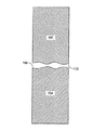
図1は、2つの面間の境界面を示す断面図である。このように2つの面間の境界面を大きく拡大した図では、第1の面102を持つ第1の物体100を、第2の面106を持つ第2の物体104と接触させる。どちらの面も完全に平坦ではないことから、これら2つの面が不完全に合わさる。このような不完全な境界面は、これら2つの物体間の境界面に熱接触抵抗をもたらす。
FIG. 1 is a sectional view showing a boundary surface between two surfaces. In the figure where the boundary surface between the two surfaces is greatly enlarged in this way, the
図2は、2つの熱伝導体間の境界面を経る、温度と位置のグラフである。このように互いに接合された2つの熱伝導体の図において、間にある熱伝導の境界面210を含む2つの熱伝導体の断面図の下に、温度と位置のグラフが示されている。第1の熱伝導体200は、第2の熱伝導体202と接合されて、これらの熱伝導体が接合する個所に、熱伝導の境界面210をもたらす。図1に示されるように、これら2つの熱伝導体間のこの境界面は、完全な接合個所ではなく、熱伝導の境界面210に熱接触抵抗をもたらす。熱エネルギーが、熱204として、第1の熱伝導体200に入り込み、第1の熱伝導体200を通って第2の熱伝導体202に移った後で、熱206として第2の熱伝導体から出るときには、この熱エネルギーは、これら2つの熱伝導体間に存する熱伝導の境界面210を通らなければならない。この熱エネルギーは、位置208と温度T1 214にて、第1の熱伝導体200に入り込んで、第1の熱伝導体200を通過すると、温度T2 216まで低下する。これら2つの熱伝導体間に存する熱伝導の境界面210では、熱エネルギーは、熱接触抵抗に打ち勝たなければならない。また、熱エネルギーが第2の熱伝導体202に入り込むと、温度が、温度T3 218まで低下する。熱エネルギーが第2の熱伝導体202を通過し、位置212で熱206として放射されると、温度は、温度T4 220まで低下する。
FIG. 2 is a graph of temperature and position through an interface between two thermal conductors. In the diagram of the two heat conductors thus joined together, a graph of temperature and position is shown below the cross-sectional view of the two heat conductors, including the
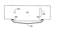
図3Aは、本発明によるサーマルインターフェース・プレート・アセンブリの実施形態の一例を示す正面図である。第1の開口306(この実施形態では、丸穴)と第2の開口308(この実施形態では、長穴)を含むサーマルインターフェース・プレート300は、アルミニウムまたは銅などの任意の熱伝導性材料から作られている。第1の開口306は、複数のサーマルインターフェース・プレート300を結集しておき、かつ、本発明の特定の実施で必要とされるときに複数のサーマルインターフェース・プレート300に圧縮を加える(プレート積層方向に沿う力を加える)ために使用されるロッドを受け入れるよう(貫通可能)に、必要に応じて任意の形状であってもよい。例示した本発明の実施形態における第2の開口308は、このロッドを、少なくとも1つの方向に移動可能に構成されている。本発明の他の実施形態では、厚さの調整能力を必要としないことがあり、また、第2の開口として第2の穴(丸穴)を利用することもある。サーマルインターフェース・プレート300の1つの側縁に沿って2つの爪部302が設けられている。爪部302は、ばね304を取付け可能に構成されている。当業者であれば、ばね304をプレート300に取り付ける広範な方法(すべて、本発明の範囲内にある)があることが理解されよう。さらに、広範なばねの設計および構成も、本発明の範囲内で利用されることがある。図3Aおよび3Bは、ばね304をプレート300に取り付ける方法の一例を示す本発明の可能な一実施形態を単に表わしたものにすぎない。ばね304は、サーマルインターフェース・パッドに流れる熱流には重要でないから、熱伝導性の材料で作る必要はない。むしろ、このばねの材料は、その熱特性を無視して必要な機械特性を有するものが選択されることがある。第1の開口306、第2の開口308、ばね304を含む完成したプレート300を、サーマルインターフェース・プレート・アセンブリと呼ぶ。
FIG. 3A is a front view showing an example of an embodiment of a thermal interface plate assembly according to the present invention. The
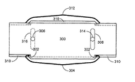
図3Bは、本発明による、図3Aに示すサーマルインターフェース・プレート・アセンブリを複数含むサーマルインターフェース・パッドの実施形態の一例を示す正面図である。図3Aに示すサーマルインターフェース・プレート・アセンブリが、複数の同様なサーマルインターフェース・プレート・アセンブリ(をスタックしたもの)の最上部に位置する状態で図示されている。交互に配列されたプレート・アセンブリは、このサーマルインターフェース・パッド内で(サーマルインターフェース・パッドの延在方向、あるいはそれぞれのサーマルインターフェース・パッドが隣接するパッドと接触する面にほぼ直交する向きの回転軸まわりに)、互いに約180度、回される。このようにプレート・アセンブリを交互に配列させると、完成したサーマルインターフェース・パッドの対向する面上に複数のばねが付けられたパッドが得られる。本発明の実施形態の一例では、個々のサーマルインターフェース・プレートは、隣り合ったプレートの爪部が重なり合う(爪部が、相隣するサーマルインターフェース・プレートの一部で覆われる)ように構成される。このような重なり合いを利用して、ばねを、それぞれのプレートに取り付けられた状態に維持しておく(外れ止めとして機能する)ことができる。第2のプレート310は、第1のプレート300のすぐ後ろに見えてもよい。第1のプレート300は、第1の開口306、第2の開口308、爪部302、ばね304を含む。第2のプレート310は、第1の開口314(この実施形態では、丸穴)、第2の開口316(この実施形態では、長穴)、爪部、および、第2のプレート310の爪部に取り付けられたばね312を含む。交互配列されたこれらのプレートは、互いに約180度、回されるから、ばねが上向きにあるプレート(図3Bにおいては第2のプレート310)の丸穴が、ばねが下向きにあるプレート(図3Bにおいては第1のプレート300)の長穴に揃える(隣接する)ことに注意されたい。同様に、ばねが上向きにあるプレートの長穴が、ばねが下向きにあるプレートの丸穴に揃える(隣接する)。次に、2本のロッドが、長穴の中で垂直方向(長穴の延在する方向)に沿って摺動できる状態で、双方の組の丸穴にロッドが差し込まれることがある。これにより、サーマルインターフェース・パッドの厚さ(図3Bの上下方向に沿う寸法)は、丸穴と長穴の寸法で定められる限度内で調整できる。ナットとともに、ねじ付きロッドを使用して、サーマルインターフェース・パッドを所望の厚さにした状態で、プレート・アセンブリのスタックを締め付ける(結束する)ことも可能である。このようにスタックを締め付けることはまた、隣り合ったプレート間に圧力を加えることもでき、それにより、プレート間の熱導電率が大幅に向上して、このサーマルインターフェース・パッド内のどんなホットスポット(熱点、過熱点)があっても、そこから放熱させることができる。
FIG. 3B is a front view illustrating an example of an embodiment of a thermal interface pad including a plurality of the thermal interface plate assemblies shown in FIG. 3A according to the present invention. The thermal interface plate assembly shown in FIG. 3A is shown at the top of a plurality (stacked) of similar thermal interface plate assemblies. The alternately arranged plate assemblies are rotated within this thermal interface pad (in the direction in which the thermal interface pads extend or in a direction substantially perpendicular to the plane where each thermal interface pad contacts adjacent pads). Around), about 180 degrees with respect to each other. This alternating arrangement of plate assemblies results in a spring loaded pad on the opposing surface of the completed thermal interface pad. In one example of an embodiment of the present invention, the individual thermal interface plates are configured such that the claws of adjacent plates overlap (the claws are covered by portions of adjacent thermal interface plates). . Utilizing such an overlap, the spring can be kept attached to the respective plate (functioning as a stopper). The
本発明の一部の実施形態は、個々のプレートが動けなくなる程に、そのスタックを締め付ける必要はないことに留意されたい。本発明の一部の実施形態は、プレート間に熱を流せるが、それでも、プレートが相対的に移動できるようにするくらいの圧力を、そのスタックに加えるために、ばね、または他の装置を利用することもある。本発明の可能な一実施形態は、プレートの丸穴に通るねじ付きロッドを利用しており、ロッドの両端部のナットと、プレート・アセンブリとの間にばねを設けて、プレート・アセンブリに圧力(プレート・アセンブリの積層方向に沿う力)を与えるが、それでも、プレートが相対的に移動できるようにしている。 It should be noted that some embodiments of the present invention do not require that the stack be tightened so that the individual plates become immobile. Some embodiments of the present invention utilize springs or other devices to apply heat to the stack that allows heat to flow between the plates, but still allows the plates to move relative to one another. Sometimes. One possible embodiment of the present invention utilizes a threaded rod that passes through a round hole in the plate and provides a spring between the nuts at both ends of the rod and the plate assembly to provide pressure to the plate assembly. (Force along the stacking direction of the plate assembly), but still allows the plates to move relatively.
それぞれのプレートに取り付けられたばねは、主として、熱吸収装置および発熱する装置の境界面(対向面)に圧縮力(押圧力)を加えるのに役立つ。これらの隣り合った装置に対するばねの接触面積は比較的小さいので、ばねを通って熱が伝達されることはほとんどない。熱は、プレートの側縁を経てプレート・アセンブリに入り、次に、隣り合ったプレートに伝達した後で、交互配列されたプレートの側縁を経てプレート・アセンブリから出る。 The springs attached to each plate serve primarily to apply a compressive force (pressing force) to the interface (opposite surface) between the heat absorbing device and the heat generating device. Since the contact area of the spring with these adjacent devices is relatively small, little heat is transferred through the spring. Heat enters the plate assembly via the side edges of the plates and then exits the plate assembly via the side edges of the interleaved plates after being transferred to adjacent plates.
本発明の他の実施形態は、本発明の範囲内で、特定の用途ごとに必要に応じて、丸穴と長穴を任意の組合せでいくつでも使用できることに留意されたい。図には丸穴が示されているが、本発明の範囲内で、どんな形状でも利用できる。ロッドは、プレートのスタックを結集しておいて、そのスタックに圧縮力(プレートの積層方向に沿う力)を加えるために、一端または両端にナットが付いているねじボルトであることもある。本発明の他の実施形態は、プレートのスタックを結集しておくために、ねじ付きロッドの代りに摩擦嵌合ロッド、あるいは他の任意の手段を利用することもある。本発明の一部の実施形態では、高さ調整が必要でなければ、プレートは、丸穴に入れるロッド以外の手段(例えば、接着剤またははんだ)を用いて、互いに恒久的に固定されることがある。接着剤またははんだは、それらが熱伝導性のものであれば、このサーマルインターフェース・パッドに必要とされる剛性も提供することに加えて、プレートからプレートへと熱を伝達できるようにすることにもなる。 It is noted that other embodiments of the present invention may use any number of round holes and slots in any combination within the scope of the present invention as needed for a particular application. Although a round hole is shown in the figures, any shape may be utilized within the scope of the present invention. The rod may be a threaded bolt with nuts at one or both ends to hold the stack of plates together and apply a compressive force (force along the stacking direction of the plates) to the stack. Other embodiments of the present invention may utilize a friction fit rod, or any other means, instead of a threaded rod to keep the stack of plates together. In some embodiments of the invention, if height adjustment is not required, the plates may be permanently fixed to each other using means other than rods into round holes (eg, glue or solder). There is. The adhesive or solder, if they are thermally conductive, will provide the required stiffness for this thermal interface pad, as well as allow for the transfer of heat from plate to plate. Also.
本発明の他の実施形態は、長穴と丸穴の代りに、プレートに2つの長穴を用いることもある。これにより、このサーマルインターフェース・パッドの厚さは、このプレート・アセンブリの全域で変わることができる。したがって、このサーマルインターフェース・パッドは、サーマル・グリースまたは伝導性パッドで満たせないくらいに凹凸の多い2つの面間のサーマルインターフェースとして利用されることもある。 Other embodiments of the present invention may use two slots in the plate instead of slots and round holes. This allows the thickness of the thermal interface pad to vary across the plate assembly. Thus, the thermal interface pad may be used as a thermal interface between two surfaces that are too uneven to be filled with thermal grease or a conductive pad.
このサーマルインターフェース・パッドを作り出すときに用いられるサーマルインターフェース・プレート・アセンブリの数を変更すれば、このサーマルインターフェース・パッドの奥行き(スタック方向の寸法)が変えられることに留意されたい。さらに、このサーマルインターフェース・パッドの幅(図3Bの上下方向に沿う寸法)も、サーマルインターフェース・プレートの幅で決定される。このサーマルインターフェース・パッドの幅は、本発明の範囲内で、無制限に変えることができる。 Note that changing the number of thermal interface plate assemblies used to create the thermal interface pad changes the depth (dimension in the stacking direction) of the thermal interface pad. Further, the width of the thermal interface pad (the dimension along the vertical direction in FIG. 3B) is also determined by the width of the thermal interface plate. The width of this thermal interface pad can be varied without limitation within the scope of the present invention.
図4Aは、本発明によるサーマルインターフェース・プレート・アセンブリの実施形態の一例を示す正面図である。本発明の実施形態の例では、サーマルインターフェース・プレート・アセンブリは、一対のばね部材402、第1の開口404(この実施形態では、丸穴)、第2の開口406(この実施形態では、長穴)を含むサーマルインターフェース・プレート400を構成することで、作り出される。本発明の一部の実施形態では、ばね部材402は、サーマルインターフェース・プレート400とは別に製作され、製造中に、はんだ付けまたは溶接などの処理を通じて、サーマルインターフェース・プレート400に機械的に固定されることがある。このサーマルインターフェース・プレートは、アルミニウムまたは銅などの任意の熱伝導性の材料から作られることがある。このばね部材は、必ずしも、このサーマルインターフェース・プレートと同じ材料で作る必要はない。このばね部材は、このサーマルインターフェース・パッドに流れる熱流には重要でないから、熱伝導性の材料で作る必要はない。むしろ、このばね部材の材料は、その熱特性を無視して所望の機械特性を得るために選択されることがある。図3Aに示される本発明の実施形態と同様に、第1の開口404と第2の開口406は、約180度回された状態で隣接するサーマルインターフェース・プレート400中の対応する第2の開口406と第1の開口404と揃うように構成されている。このことから、同じサーマルインターフェース・プレート・アセンブリを複数組み合わせて構成されたサーマルインターフェース・パッドの厚さ(図4Aまたは4Bの上下方向に沿う寸法)を調整可能にすることができる。本発明の一部の実施形態では、厚さを調整可能とすることは、必要でないし、かつ望ましくない場合がある。そのような場合には、サーマルインターフェース・プレート400は、1つまたは複数の丸穴404を付け、かつ長穴406なしで構成され、したがって、厚さの調整能力が削除される。
FIG. 4A is a front view showing an example of an embodiment of a thermal interface plate assembly according to the present invention. In an example embodiment of the invention, the thermal interface plate assembly includes a pair of
図4Bは、本発明による、図4Aに示されるサーマルインターフェース・プレート・アセンブリを複数含むサーマルインターフェース・パッドの実施形態を例示する正面図である。図4Aに示されるサーマルインターフェース・プレート・アセンブリ400が、複数の同様なサーマルインターフェース・プレート・アセンブリの最上部に配置されたかたちで示されている。交互配列されたプレート・アセンブリは、このサーマルインターフェース・パッド内で、交互に約180度、回される。このようにプレート・アセンブリが交互配列されると、完成状態のサーマルインターフェース・パッドの対向する面上に複数のばねが付けられたパッドが得られる。第1のプレートは、第1の開口404(この実施形態では、丸穴)、第2の開口406(この実施形態では、長穴)、2つのばね部材402を含む。第2のプレートは、第1の開口410(この実施形態では、丸穴)、第2の開口412(この実施形態では、長穴)、一対のばね部材408を含む。交互配列されたプレートは、互いに約180度、回されて配置されるから、図4Bにおいてばねが上向きにあるプレートの丸穴が、ばねが下向きにあるプレートの長穴と隣接するように揃えられることに注意されたい。同様に、ばねが上向きにあるプレートの長穴が、ばねが下向きにあるプレートの丸穴と隣接するように揃えられる。次に、2本のロッドが、長穴の中で垂直方向(長穴の延在方向に沿う方向)に摺動可能に、双方の組の丸穴にロッドを差し込むことがある。これにより、サーマルインターフェース・パッドの厚さ(図4Bの上下方向に沿う寸法)は、丸穴と長穴の寸法で定められる限度内で調整できる。ナットとともに、ねじ付きロッドを使用して、サーマルインターフェース・パッドが所望の厚さに設定された状態で、プレート・アセンブリのスタックを締め付けることがある。このようにスタックを締め付けることはまた、隣り合ったプレート間に圧力も加えることができ、それにより、プレート間の熱導電率が大幅に向上して、このサーマルインターフェース・パッド内のどんなホットスポットからも放熱させることができる。
FIG. 4B is a front view illustrating an embodiment of a thermal interface pad including a plurality of thermal interface plate assemblies shown in FIG. 4A, according to the present invention. The thermal
図5Aは、本発明によるサーマルインターフェース・プレート・アセンブリの実施形態の一例を示す正面図である。本発明のこの実施形態の例は、図3Aに示されるものと似ている。しかしながら、サーマルインターフェース・プレート本体は、図3Aのものよりも高く(図5Aの上下方向に沿う寸法が大きく)、さらに、上側の側縁(ばね504の取り付けられた側縁と対向する側縁)に沿って庇状、あるいは棚状に張り出した出張り518も含む。第1の開口506(この実施形態では、丸穴)と第2の開口508(この実施形態では、長穴)を含むサーマルインターフェース・プレート500は、アルミニウムまたは銅などの任意の熱伝導性材料から作られている。第1の開口506は、複数のサーマルインターフェース・プレート500を結集しておき、かつ、本発明の特定の実施で必要とされるときに複数のサーマルインターフェース・プレート500に圧縮を加えるために使用されるロッドを受け入れ可能に、所望の任意の形状であってもよい。本発明のこの実施形態の例における第2の開口508は、このロッドを、少なくとも1つの方向に移動可能に構成されている。本発明の他の実施形態は、サーマルインターフェース・パッドの厚さ(図5Aの上下方向に沿う寸法)の調整能力を必要としない場合があり、その場合には長穴の代りに丸穴を利用することもできる。サーマルインターフェース・プレート500の1つの側縁に沿って2つの爪部502が設けられている。爪部502は、ばね504を装着可能に構成されている。第1の開口506、第2の開口508、ばね504を含む完成したプレート500を、サーマルインターフェース・プレート・アセンブリと呼ぶ。上側の側縁に沿った出張り518は、サーマルインターフェース・パッドと、これに隣接する発熱する装置または熱吸収装置との間の熱伝達を向上させるために用いられる。厚さがプレート500に等しい出張り518を作る(プレート500の積層方向に沿う厚さと、出張り518がプレート500の表面からプレート500の積層方向に沿って突出している寸法とを揃える)ことで、(出張り518が無い場合に比して)隣接する装置に接触する面積が二倍になり、その結果、熱接触抵抗が小さくなる。
FIG. 5A is a front view showing an example of an embodiment of a thermal interface plate assembly according to the present invention. An example of this embodiment of the invention is similar to that shown in FIG. 3A. However, the thermal interface plate body is higher than that of FIG. 3A (the dimension along the vertical direction of FIG. 5A is large), and further, the upper side edge (side edge opposite to the side edge where the
図5Bは、本発明による、図5Aに示すサーマルインターフェース・プレート・アセンブリを複数含むサーマルインターフェース・パッドの実施形態を例示する正面図である。図5Aに示すサーマルインターフェース・プレート・アセンブリが、複数の同様なサーマルインターフェース・プレート・アセンブリをスタックしたものの最上部に位置する状態で図示されている。交互配列されたプレート・アセンブリは、このサーマルインターフェース・パッド内で、交互に約180度、回される。このようにプレート・アセンブリを交互配列させると、完成状態のサーマルインターフェース・パッドの対向する面に複数のばねが位置しているパッドが得られる。本発明のこの実施形態の例では、個々のサーマルインターフェース・プレートは、隣り合ったプレートの爪部およびばねに重なり合う(爪部およびばねを覆う)ように構成される。出張りは、外部装置とのどんな接触からも、ばねを保護するために用いられる。それぞれのばねは、2枚の隣り合ったサーマルインターフェース・プレートで包囲されていてもよい。第2のプレート510は、第1のプレート500のすぐ後ろに見えていてもよい。第1のプレートは、第1の開口506、第2の開口508、出張り518、爪部502、ばね504を含む。第2のプレート510は、第1の開口514(この実施形態では、丸穴)、第2の開口516(この実施形態では、長穴)、出張り520、爪部、および、第2のプレート510の爪部に取り付けられたばね512を含む。交互配列されたプレートは、互いに約180度、回されていて、ばねが上向きにある(図5Bにおいてばねが上側にある)プレートの丸穴が、ばねが下向きにある(図5Bにおいて下側にある)プレートの長穴と隣接することに注意されたい。同様に、ばねが上向きにあるプレートの長穴が、ばねが下向きにあるプレートの丸穴と隣接する。次に、2本のロッドが、長穴の中で、長穴の延在方向に沿って摺動可能な状態で、双方の組の丸穴にロッドを差し込むことがある。これにより、サーマルインターフェース・パッドの厚さ(図5Bの上下方向に沿う寸法)は、丸穴と長穴の寸法で定められる限度内で調整できる。ナットとともに、ねじ付きロッドを使用して、サーマルインターフェース・パッドを所望の厚さに設定した状態で、プレート・アセンブリのスタックを締め付けることもできる。このようにスタックを締め付けることはまた、隣り合ったプレート間に圧力を加えることもでき、それにより、プレート間の熱導電率が大幅に向上して、このサーマルインターフェース・パッド内のどんなホットスポットからの放熱も可能とすることができる。
FIG. 5B is a front view illustrating an embodiment of a thermal interface pad including a plurality of thermal interface plate assemblies shown in FIG. 5A according to the present invention. The thermal interface plate assembly shown in FIG. 5A is shown at the top of a stack of a plurality of similar thermal interface plate assemblies. The alternating plate assemblies are alternately rotated about 180 degrees within the thermal interface pad. This alternating arrangement of plate assemblies results in a pad having a plurality of springs located on opposite sides of the completed thermal interface pad. In an example of this embodiment of the present invention, the individual thermal interface plates are configured to overlap (cover) the pawls and springs of adjacent plates. The ledge is used to protect the spring from any contact with external devices. Each spring may be surrounded by two adjacent thermal interface plates. The
図6Aは、図5Bに示す本発明によるサーマルインターフェース・パッドの実施形態の例を切断線B−Bに沿う断面で示した図である。この断面図には、第1のプレート500と第2のプレート510が、それらのプレートの背後に積み重ねられた他の複数のサーマルインターフェース・プレート・アセンブリとともに示されている。この断面図は、これらのばねがそれぞれ、隣り合ったプレートの出張りで包囲されていることを示している。例えば、第2のプレート510のばね512は、第1のプレート500で覆われ、また、この第1のプレートの背後のプレートからの出張りは、サーマルインターフェース・パッドの最上部に固定されるどの装置にも、ばねを接触させないようにする。第1のプレート500のばね504は、第2のプレート510の出張り520で保護される。実際の使用では、ばね504を第1のプレート500に取り付けておくために、エンド・プレートを第1のプレート500の上(図6Aにおいては右側に相当)に置くこともできる。本発明の実施形態の例では、発熱する装置600および熱吸収装置604が、サーマルインターフェース・パッドと熱的に結合された状態で示されている。発熱する装置600とサーマルインターフェース・パッドとの間の共通面602をサーマル・グリースで覆って、発熱する装置600とサーマルインターフェース・パッドとの間の熱抵抗を減らすことがある。同様に、サーマルインターフェース・パッドと熱吸収装置604との間の共通面606をサーマル・グリースで覆って、熱抵抗を減らすことがある。発熱する装置600からの熱は、第2のプレート510上の出張り520や、第2のプレート510と同じ向きに積層されている他のプレートの側縁を通って、サーマルインターフェース・パッドに入り込む。次に、熱は、第2のプレート510と同じ向きに積層されている他のプレートの全体にわたって広がって、第1のプレート500と同じ向きに積層されている他のプレートに入り込む。熱は、出張り518や、第1のプレート500と同じ向きに積層されている他のプレートの側縁から、熱吸収装置604に伝達される。これらの出張りにより、熱吸収装置および発熱する装置と、サーマルインターフェース・パッドとの間の接触面積を、事実上二倍にしていることに注意されたい。
FIG. 6A is a diagram showing an example of the embodiment of the thermal interface pad according to the present invention shown in FIG. 5B in a cross section taken along a cutting line BB. In this cross section, a
図6Bは、発熱する装置600と熱吸収装置604とが互いに近づき合って、図6Aに示す本発明によるサーマルインターフェース・パッドの一部が圧縮されている様子を示す、断面図である。
FIG. 6B is a cross-sectional view showing the
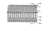
図7は、図5Bに示す本発明によるサーマルインターフェース・パッドの実施形態が圧縮されている状態を示す正面図である。本発明の実施形態の例では、このサーマルインターフェース・パッドの厚さ(図7の上下方向に沿う寸法)を減らすことが望ましい場合がある。これは、このサーマルインターフェース・パッドを垂直方向に圧縮した後で、上述のように、1つまたは複数のねじ付きロッド、または他の方法を利用して、このプレート・アセンブリを互いに固定することで、達成することも可能である。第1の開口706(この実施形態では、丸穴)、第2の開口708(この実施形態では、長穴)、出張り718、爪部702、ばね704を含む第1のプレート・アセンブリ700が示されている。第1の開口714(この実施形態では、丸穴)、第2の開口716(この実施形態では、長穴)、出張り720、爪部、および、ばね712を含む第2のプレート・アセンブリ710が、第1のプレート・アセンブリ700の真下に示されている。このばねは、隣り合ったサーマルインターフェース・プレートの出張りによって圧縮されており、また丸穴と長穴は、相対的に移動していることに留意されたい。このサーマルインターフェース・パッドは、複数のサーマルインターフェース・プレート・アセンブリを積み重ねた後、2本のボルトを丸穴にねじ込んで、ナットを、それらのボルトに固定することで完成するものであってもよい。ナットは、個々のサーマルインターフェース・プレート・アセンブリを移動させないようにし、かつ、隣り合ったプレート・アセンブリ間の熱伝導率を向上させる程度に締め付けられてもよい。本発明の他の実施形態では、ナットのそれぞれの下に、ボルトを取り囲むばねを含んでいてもよい。これらのばねは、これらのプレートを相対摺動可能とし、このサーマルインターフェース・パッドが挿入される空間の形状に対応した形にサーマルインターフェース・パッドを追従できるようにしつつ、個々のプレートを互いに接触させておくのに充分な圧力を与えることもできる。
FIG. 7 is a front view showing the embodiment of the thermal interface pad according to the present invention shown in FIG. 5B in a compressed state. In the example of the embodiment of the present invention, it may be desirable to reduce the thickness (the dimension along the vertical direction in FIG. 7) of the thermal interface pad. This is accomplished by vertically compressing the thermal interface pad and then securing the plate assemblies together using one or more threaded rods, or other methods, as described above. , It is also possible to achieve. A
図8は、図7に示す本発明によるサーマルインターフェース・パッドの実施形態を例示する、図7の切断線C−Cに沿う断面図である。図8と図6を比較すると、隣り合ったプレートの丸穴と長穴が相対的に(図8の上下方向に沿って)移動していることが判る。本発明の他の実施形態は、本発明の任意の所与の用途で必要とされるのに応じて、丸穴と長穴のどんな組合せでも利用できることに留意されたい。例えば、ただ1つのサーマルインターフェース・パッドを用いて様々な間隔のギャップを埋めることが必要なときには、このサーマルインターフェース・パッド内の異なる位置で、プレート間の異なるオフセットを可能にするために、1個の長穴と1個の丸穴の代りに、2個の長穴を利用することが必要な場合もある。 FIG. 8 is a cross-sectional view taken along section line CC of FIG. 7 illustrating the embodiment of the thermal interface pad according to the present invention shown in FIG. Comparing FIG. 8 with FIG. 6, it can be seen that the round holes and the elongated holes of the adjacent plates are relatively moving (along the vertical direction in FIG. 8). It should be noted that other embodiments of the present invention can utilize any combination of round and oblong holes as required for any given application of the present invention. For example, when it is necessary to use only one thermal interface pad to fill gaps of various spacings, different locations within this thermal interface pad may require one to allow for different offsets between the plates. It may be necessary to use two slots instead of a slot and one round.
図9は、図7に示す本発明によるサーマルインターフェース・パッドの実施形態を例示する、図7の切断線D−Dに沿う断面図である。このサーマルインターフェース・パッドの組立てを完成させるために、このサーマルインターフェース・パッドの左側の丸穴706と長穴716にロッド900を差し込む。
FIG. 9 is a cross-sectional view taken along section line DD of FIG. 7 illustrating the embodiment of the thermal interface pad according to the present invention shown in FIG. To complete the assembly of the thermal interface pad, the
図10は、図7に示す本発明によるサーマルインターフェース・パッドの実施形態を例示する、図7の切断線E−Eに沿う断面図である。このサーマルインターフェース・パッドの組立てを完成させるために、このサーマルインターフェース・パッドの右側の丸穴714と長穴708にロッド1000を差し込む。
FIG. 10 is a cross-sectional view taken along section line EE of FIG. 7 illustrating the embodiment of the thermal interface pad according to the present invention shown in FIG. In order to complete the assembly of the thermal interface pad, the
図11Aは、本発明によるサーマルインターフェース・プレート・アセンブリの正面図である。本発明の実施形態の例では、図4Aに示されるものと似ている。しかしながら、サーマルインターフェース本体は、図4Aのものよりも高く(図11Aの上下方向に沿う寸法が大きく)、さらに、上側の側縁に沿って庇状、あるいは棚状に張り出した出張り1114も含む。2つのばね部材1102、第1の開口1104(この実施形態では、丸穴)と第2の開口1106(この実施形態では、長穴)を含むサーマルインターフェース・プレート1100は、アルミニウムまたは銅などの任意の熱伝導性材料から作られている。本発明の一部の実施形態では、ばね部材1102は、サーマルインターフェース・プレート1100とは別に製作され、製造中に、はんだ付けまたは溶接などの処理を通じて、サーマルインターフェース・プレート1100に機械的に固定されることがある。本発明の範囲内で、ばね部材1102をいくつでも使用できることに留意されたい。第1の開口1104は、複数のサーマルインターフェース・プレート1100を結集しておき、かつ、本発明の特定の実施で必要とされるときに複数のサーマルインターフェース・プレート1100に圧縮を加える(プレートをスタックする方向に力を加える)ために使用されるロッドを受け入れるように、必要とされる任意の形状であってもよい。図4Aに示される本発明の実施形態と同様に、第1の開口1104および第2の開口1106は、サーマルインターフェース・プレート1100の面内で約180度回させて組み合わされた、隣接するサーマルインターフェース・プレート1100中の対応する第2の開口1106および第1の開口1104と揃う(位置が合う)ように構成されている。このことから、同じサーマルインターフェース・プレート・アセンブリを複数組み合わせて構成されたサーマルインターフェース・パッドの厚さ(図11Aの上下方向に沿う寸法)を調整可能にすることができる。本発明の一部の実施形態では、厚さを調整可能とすることは、必要でないし、かつ望ましくない場合もあり得る。そのような場合には、サーマルインターフェース・プレート1100は、1つまたは複数の丸穴404を付け、かつ長穴406なしで構成され、したがって、厚さの調整能力が削除される。
FIG. 11A is a front view of a thermal interface plate assembly according to the present invention. An example of an embodiment of the present invention is similar to that shown in FIG. 4A. However, the thermal interface body is higher than that of FIG. 4A (the dimension along the vertical direction in FIG. 11A is large), and further includes a
図11Bは、本発明による、図11Aに示すサーマルインターフェース・プレート・アセンブリを複数含むサーマルインターフェース・パッドの実施形態の例を示す正面図である。図11Aに示すサーマルインターフェース・プレート・アセンブリが、複数の同様なサーマルインターフェース・プレート・アセンブリのスタックの最上部に位置する状態で示されている。交互配列されたプレート・アセンブリは、このサーマルインターフェース・パッド内で、交互に約180度、回される。このようにプレート・アセンブリを交互配列させると、完成したサーマルインターフェース・パッドの対向する面に複数のばねが位置しているパッドが得られる。本発明のこの実施形態の例では、個々のサーマルインターフェース・プレートは、隣り合ったプレートの一対のばね部材に重なり合う(ばね部材を覆う)ように構成される。出張りは、外部装置とのどんな接触からも、ばね部材を保護するために用いられる。それぞれのばね部材は、2枚の隣り合ったサーマルインターフェース・プレートで包囲されていてもよい。第2のプレート1118は、第1のプレート1100のすぐ後ろに見えることもある。第1のプレートは、第1の開口1104(この実施形態では、丸穴)、第2の開口1106(この実施形態では、長穴)、出張り1114、一対のばね部材1102を含む。第2のプレート1118は、第1の開口1110(この実施形態では、丸穴)、第2の開口1112(この実施形態では、長穴)、出張り1116、および、第2のプレートに取り付けられた一対のばね部材1108を含む。交互配列されたプレートは、互いに約180度、回されるから、図11Bにおいてばねが上向きにあるプレートの丸穴を、ばねが下向きにあるプレートの長穴に揃えられることに注意されたい。同様に、ばねが上向きにあるプレートの長穴を、ばねが下向きにあるプレートの丸穴に揃えられる。次に、2本のロッドが、長穴の中で垂直方向(長穴の延在方向)に沿って摺動可能に、双方の組の丸穴にロッドを差し込んでもよい。これにより、サーマルインターフェース・パッドの厚さ(図11Bの上下方向に沿う寸法)は、丸穴と長穴の寸法で定められる限度内で調整できる。ナットとともに、ねじ付きロッドを使用して、サーマルインターフェース・パッドの厚さを設定した状態で、プレート・アセンブリのスタックを締め付けることがある。このようにスタックを締め付けることはまた、隣り合ったプレート間に圧力を加えることができ、それにより、プレート間の熱導電率が大幅に向上して、このサーマルインターフェース・パッド内のどんなホットスポットもさらに放散させることができる。
FIG. 11B is a front view illustrating an example of an embodiment of a thermal interface pad including a plurality of thermal interface plate assemblies shown in FIG. 11A according to the present invention. The thermal interface plate assembly shown in FIG. 11A is shown at the top of a stack of a plurality of similar thermal interface plate assemblies. The alternating plate assemblies are alternately rotated about 180 degrees within the thermal interface pad. Such an alternating arrangement of plate assemblies results in a pad having a plurality of springs located on opposite sides of the completed thermal interface pad. In an example of this embodiment of the present invention, each thermal interface plate is configured to overlap (cover) a pair of spring members of an adjacent plate. The lug is used to protect the spring member from any contact with external devices. Each spring member may be surrounded by two adjacent thermal interface plates. The
図12Aは、図11Bに示した本発明によるサーマルインターフェース・パッドの実施形態の一例で、切断線F−Fに沿う断面図である。 FIG. 12A is a cross-sectional view of the thermal interface pad according to the embodiment of the present invention shown in FIG. 11B, taken along section line FF.
図12Bは、図11Bに示した本発明によるサーマルインターフェース・パッドの実施形態の一例が圧縮された状態にある様子を示す、切断線F−Fに沿う断面図である。本発明のこの実施形態の例では、半数のプレートの長穴と丸穴は、残りのプレートの長穴と丸穴に対して、垂直方向(長穴の延在方向)に移動していることに留意されたい。ボルトを、これらの組の丸穴のそれぞれに差し込み、またナットを、このボルトに締め付けて、このサーマルインターフェース・パッドを圧縮することがあり、それにより、個々のプレート・アセンブリの移動が妨げられ、かつ、個々のプレート・アセンブリ間の熱伝導率が向上する。 FIG. 12B is a cross-sectional view taken along section line FF showing an example of the embodiment of the thermal interface pad according to the present invention shown in FIG. 11B in a compressed state. In the example of this embodiment of the present invention, the long hole and the round hole of half of the plates move in the vertical direction (the extending direction of the long hole) with respect to the long hole and the round hole of the remaining plates. Please note. Bolts may be inserted into each of these sets of round holes, and nuts may be tightened on the bolts to compress the thermal interface pad, thereby hindering movement of the individual plate assemblies, In addition, the thermal conductivity between the individual plate assemblies is improved.
図13は、本発明によるサーマルインターフェース・プレート・アセンブリの実施形態の一例を示す正面図である。本発明のこの例証実施形態では、第1の開口1304(この例では、丸穴)、第2の開口1306(この例では、長穴)、および、一側縁に沿った切欠き1302を含むプレート1300が構成される。エラストマー伝導体(柔軟性、あるいは弾性を有する熱伝導体。以下、「エラストマー伝導体」と称する)1308の一部が、プレート1300の側縁から突出するように、エラストマー伝導体1308を、この切欠きに入れる。本発明の前述の実施形態に述べられるように、これらのプレート・アセンブリは、交互配列させてスタックさせたときに、その厚さ(図13の上下方向に沿う寸法)が調整可能であり、また、エラストマー伝導体1308は、サーマルインターフェース・プレートと発熱する装置および熱吸収装置との間に介在して、これら発熱する装置および熱吸収装置に対して低熱抵抗(大きい熱伝導率)の接触を与える。
FIG. 13 is a front view showing an example of the embodiment of the thermal interface plate assembly according to the present invention. In this illustrative embodiment of the invention, a first opening 1304 (in this example, a round hole), a second opening 1306 (in this example, a slot), and a
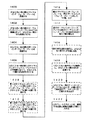
図14は、本発明による、図3Aと図3Bに示されるものと同様なサーマルインターフェース・パッドを組み立てる方法の実施形態を例示する流れ図である。ステップ1400において、少なくとも一枚の第1のサーマルインターフェース・プレートを用意する。ステップ1402において、少なくとも一枚の第1のサーマルインターフェース・プレートの1つの側縁に沿って、少なくとも一個のばねを取り付ける。ステップ1404において、少なくとも一枚の第2のサーマルインターフェース・プレートを用意する。ステップ1406において、少なくとも一枚の第2のサーマルインターフェース・プレートの1つの側縁に沿って、少なくとも一個のばねを取り付ける。オプションのステップ1408において、第1のサーマルインターフェース・プレートと第2のサーマルインターフェース・プレートに、少なくとも1つの第1の開口を設ける。オプションのステップ1410において、第1のサーマルインターフェース・プレートと第2のサーマルインターフェース・プレートに、少なくとも1つの第2の開口を設ける。ステップ1412において、第2のサーマルインターフェース・プレートを、第1のサーマルインターフェース・プレートに対して、180度、回す。ステップ1414において、第1のサーマルインターフェース・プレートと第2のサーマルインターフェース・プレートを交互に積み重ねる。オプションのステップ1416において、第1の開口と第2の開口に、少なくとも一本のロッドを差し込む。オプションのステップ1418において、少なくとも一本のロッドの端部に、少なくとも一個のばねを配置する。このばねは、スタックされたサーマルインターフェース・プレートに対して、ロッドの軸方向に沿って押圧力を与えるためのものである。オプションのステップ1420において、少なくとも一個のナットを少なくとも一本のロッドにねじ込んで、必要に応じて締め付けて、プレートのスタックへの圧縮力(ロッドの軸方向に沿う力)を生み出す。ステップ1422において、このプレートのスタックを、発熱する装置と熱吸収装置との間に入れる。
FIG. 14 is a flowchart illustrating an embodiment of a method of assembling a thermal interface pad similar to that shown in FIGS. 3A and 3B, according to the present invention. At
図15は、本発明による、図4Aと図4Bに示されるものと同様なサーマルインターフェース・パッドを組み立てる方法の実施形態を例示する流れ図である。ステップ1500において、少なくとも一枚の第1のサーマルインターフェース・プレートを用意する。ステップ1502において、少なくとも一枚の第1のサーマルインターフェース・プレートの1つの側縁に沿って、少なくとも1つのばね部材を取り付ける。ステップ1504において、少なくとも一枚の第2のサーマルインターフェース・プレートを用意する。ステップ1506において、少なくとも一枚の第2のサーマルインターフェース・プレートの1つの側縁に沿って、少なくとも1つのばね部材を取り付ける。オプションのステップ1508において、第1のサーマルインターフェース・プレートと第2のサーマルインターフェース・プレートに、少なくとも1つの第1の開口を設ける。オプションのステップ1510において、第1のサーマルインターフェース・プレートと第2のサーマルインターフェース・プレートに、少なくとも1つの第2の開口を設ける。ステップ1512において、第2のサーマルインターフェース・プレートを、第1のサーマルインターフェース・プレートに対して、180度、回す。ステップ1514において、第1のサーマルインターフェース・プレートと第2のサーマルインターフェース・プレートを交互に積み重ねる。オプションのステップ1516において、第1の開口と第2の開口に、少なくとも一本のロッドを差し込む。オプションのステップ1518において、少なくとも一本のロッドの端部に、少なくとも一個のばねを配置する。このばねは、スタックされたサーマルインターフェース・プレートに対して、ロッドの軸方向に沿って押圧力を与えるためのものである。オプションのステップ1520において、少なくとも一個のナットを少なくとも一本のロッドにねじ込んで、必要に応じて締め付けて、プレートのスタックへの圧縮力(ロッドの軸方向に沿う力)を生み出す。ステップ1522において、このプレートのスタックを、発熱する装置と熱吸収装置との間に入れる。
FIG. 15 is a flowchart illustrating an embodiment of a method of assembling a thermal interface pad similar to that shown in FIGS. 4A and 4B, according to the present invention. In
図16は、本発明による、図4Aと図4Bに示されるものと同様なサーマルインターフェース・パッドを組み立てる方法の実施形態を例示する流れ図である。ステップ1600において、少なくとも1つのばね部材を含む少なくとも一枚の第1のサーマルインターフェース・プレートを用意する。ステップ1602において、少なくとも1つのばね部材を含む少なくとも一枚の第2のサーマルインターフェース・プレートを用意する。オプションのステップ1604において、第1のサーマルインターフェース・プレートと第2のサーマルインターフェース・プレートに、少なくとも1つの第1の開口を設ける。オプションのステップ1606において、第1のサーマルインターフェース・プレートと第2のサーマルインターフェース・プレートに、少なくとも1つの第2の開口を設ける。ステップ1608において、第2のサーマルインターフェース・プレートを、第1のサーマルインターフェース・プレートに対して、180度、回す。ステップ1610において、第1のサーマルインターフェース・プレートと第2のサーマルインターフェース・プレートを交互に積み重ねる。オプションのステップ1612において、第1の開口と第2の開口に、少なくとも一本のロッドを差し込む。オプションのステップ1614において、少なくとも一本のロッドの端部に、少なくとも一個のばねを配置する。このばねは、スタックされたサーマルインターフェース・プレートに対して、ロッドの軸方向に沿って押圧力を与えるためのものである。オプションのステップ1616において、少なくとも一個のナットを少なくとも一本のロッドにねじ込んで、必要に応じて締め付けて、プレートのスタックへの圧縮力(ロッドの軸方向に沿う力)を生み出す。ステップ1618において、このプレートのスタックを、発熱する装置と熱吸収装置との間に入れる。
FIG. 16 is a flowchart illustrating an embodiment of a method of assembling a thermal interface pad similar to that shown in FIGS. 4A and 4B, according to the present invention. At
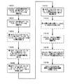
図17は、本発明による、図13に示されるものと同様なサーマルインターフェース・パッドを組み立てる方法の実施形態を例示する流れ図である。ステップ1700において、少なくとも一枚の第1のサーマルインターフェース・プレートを用意する。ステップ1702において、第1のサーマルインターフェース・プレートの少なくとも一枚の1つの側縁に沿って、切欠きを設ける。ステップ1704において、少なくとも一枚の第1のサーマルインターフェース・プレートの切欠きに、少なくとも1つのエラストマー伝導体を取り付ける。ステップ1706において、少なくとも一枚の第2のサーマルインターフェース・プレートを用意する。ステップ1708において、第2のサーマルインターフェース・プレートの少なくとも一枚の1つの側縁に沿って、切欠きを設ける。ステップ1710において、少なくとも一枚の第2のサーマルインターフェース・プレートの切欠きに、少なくとも1つのエラストマー伝導体を取り付ける。オプションのステップ1712において、第1のサーマルインターフェース・プレートと第2のサーマルインターフェース・プレートに、少なくとも1つの第1の開口を設ける。オプションのステップ1714において、第1のサーマルインターフェース・プレートと第2のサーマルインターフェース・プレートに、少なくとも1つの第2の開口を設ける。ステップ1716において、第2のサーマルインターフェース・プレートを、第1のサーマルインターフェース・プレートに対して、180度、回す。ステップ1718において、第1のサーマルインターフェース・プレートと第2のサーマルインターフェース・プレートを交互に積み重ねる。オプションのステップ1720において、第1の開口と第2の開口に、少なくとも一本のロッドを差し込む。オプションのステップ1722において、少なくとも一本のロッドの端部に、少なくとも一個のばねを配置する。このばねは、スタックされたサーマルインターフェース・プレートに対して、ロッドの軸方向に沿って押圧力を与えるためのものである。オプションのステップ1724において、少なくとも一個のナットを少なくとも一本のロッドにねじ込んで、必要に応じて締め付けて、プレートのスタックへの圧縮力(ロッドの軸方向に沿う力)を生み出す。ステップ1726において、このプレートのスタックを、発熱する装置と熱吸収装置との間に入れる。
FIG. 17 is a flowchart illustrating an embodiment of a method of assembling a thermal interface pad similar to that shown in FIG. 13 according to the present invention. At
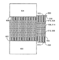
図18は、本発明によるサーマルインターフェース・プレート・アセンブリの実施形態の一例を示す正面図である。第1の開口1802(この実施形態では、丸穴)と第2の開口1804(この実施形態では、長穴)を含むサーマルインターフェース・プレート1800は、アルミニウムまたは銅などの任意の熱伝導性材料から作られている。第1の開口1802は、複数のサーマルインターフェース・プレート1800を結集しておき、かつ、本発明の特定の実施で必要とされるときに複数のサーマルインターフェース・プレート1800に圧縮を加える(プレートがスタックされている方向に沿って力を加える)ために使用されるロッドを受け入れるように、必要に応じた任意の形状であってもよい。本発明の実施形態の例における第2の開口1804は、このロッドを、少なくとも1つの方向に移動可能に構成されている。サーマルインターフェース・プレート1800はまた、第1のエラストマー開口1806(この実施形態では、このプレートの左側にある長方形の開口)と第2のエラストマー開口1808(この実施形態では、このプレートの右側にある長方形の開口)も含む。これら第1、第2のエラストマー開口1806、1808は、後述するように、伝熱性または非伝熱性の弾性体を挿入するための開口である。第1の開口1802、第2の開口1804、第1のエラストマー開口1806、第2のエラストマー開口1808を含む完成したプレート1800を、サーマルインターフェース・プレート・アセンブリと呼ぶ。複数のサーマルインターフェース・プレート・アセンブリを組み立ててサーマルインターフェース・パッドを作るときに、これらのサーマルインターフェース・プレート・アセンブリを、交互に約180度向きを変えながら積み重ねると、第1のエラストマー開口1806と第2のエラストマー開口1808にエラストマーを入れることができる。エラストマーは圧縮可能であるから、交互するプレートは、相対的に摺動することがあり、その結果、サーマルインターフェース・パッドは、その厚さ(図18の上下方向に沿う寸法)を広範に変えることができる。さらに、当業者であれば、隣り合ったプレートと接触しているサーマルインターフェース・プレート間に、大量の熱が伝達されることが理解されよう。このために、これらのエラストマーは、熱伝導性のものであってもよいが、ただし、例示した本発明の実施形態の目的によっては、必ずしも熱伝導性のものである必要はない。
FIG. 18 is a front view showing an example of the embodiment of the thermal interface plate assembly according to the present invention. The
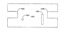
図19は、本発明によるサーマルインターフェース・プレート・アセンブリの実施形態を例示する正面図である。第1の開口1902(この実施形態では、丸穴)と第2の開口1904(この実施形態では、長穴)を含むサーマルインターフェース・プレート1900は、アルミニウムまたは銅などの任意の熱伝導性材料から作られている。第1の開口1902は、複数のサーマルインターフェース・プレート1900を結集しておき、かつ、本発明の特定の実施で必要とされるときに複数のサーマルインターフェース・プレート1900に、スタックされた方向に沿って圧縮力を加えるために使用されるロッドを受け入れるように、必要に応じて任意の形状であってもよい。本発明の実施形態の一例における第2の開口1904は、このロッドを、少なくとも1つの方向に移動可能に構成されている。サーマルインターフェース・プレート1900はまた、第1のエラストマー開口1906(この実施形態では、このプレートの左側にある切欠き)と第2のエラストマー開口1908(この実施形態では、このプレートの右側にある切欠き)も含む。これら第1、第2のエラストマー開口1906、1908は、伝熱性または非伝熱性の弾性体を挿入するための開口である。第1の開口1902、第2の開口1904、第1のエラストマー開口1906、第2のエラストマー開口1908を含む完成したプレート1900を、サーマルインターフェース・プレート・アセンブリと呼ぶ。複数のサーマルインターフェース・プレート・アセンブリを組み立ててサーマルインターフェース・パッドを作るときに、これらのサーマルインターフェース・プレート・アセンブリを、交互に約180度向きを変えながら積み重ねると、第1のエラストマー開口1906と第2のエラストマー開口1908にエラストマーを入れることができる。エラストマーは圧縮可能であるから、交互配列されたプレートは、相対的に摺動することができ、その結果、サーマルインターフェース・パッドは、その厚さ(図19の上下方向に沿う寸法)を広範に変えることができる。
FIG. 19 is a front view illustrating an embodiment of a thermal interface plate assembly according to the present invention. The
図20は、本発明によるサーマルインターフェース・プレート・アセンブリの実施形態の一例を示す正面図である。第1の開口2002(この実施形態では、丸穴)と第2の開口2004(この実施形態では、長穴)を含むサーマルインターフェース・プレート2000は、アルミニウムまたは銅などの任意の熱伝導性材料から作られている。第1の開口2002は、複数のサーマルインターフェース・プレート2000を結集しておき、かつ、本発明の特定の実施で必要とされるときに複数のサーマルインターフェース・プレート2000に対してサーマルインターフェース・プレートのスタック方向に沿って圧縮力を加えるために使用されるロッドを受け入れるように、必要に応じた任意の形状であってもよい。本発明の実施形態の一例における第2の開口2004は、このロッドを、少なくとも1つの方向に移動可能に構成されている。サーマルインターフェース・プレート2000はまた、第1のエラストマー開口2006(この実施形態では、このプレートの左下の部位にある切欠き)と第2のエラストマー開口2008(この実施形態では、このプレートの右下の部位にある切欠き)も含む。これら第1、第2のエラストマー開口2006、2008は、伝熱性または非伝熱性の弾性体を挿入するための開口である。第1の開口2002、第2の開口2004、第1のエラストマー開口2006、第2のエラストマー開口2008を含む完成したプレート2000を、サーマルインターフェース・プレート・アセンブリと呼ぶ。複数のサーマルインターフェース・プレート・アセンブリを組み立ててサーマルインターフェース・パッドを作るときに、これらのサーマルインターフェース・プレート・アセンブリを、交互に約180度向きを変えながら積み重ねると、第1のエラストマー開口2006と第2のエラストマー開口2008にエラストマーを入れることができる。エラストマーは圧縮可能であるから、交互配列されたプレートは、相対的に摺動することができ、その結果、サーマルインターフェース・パッドは、その厚さ(図20の上下方向に沿う寸法)を広範に変えることができる。
FIG. 20 is a front view showing an example of the embodiment of the thermal interface plate assembly according to the present invention. The
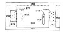
図21は、本発明による、図20に示すサーマルインターフェース・プレート・アセンブリを複数含むサーマルインターフェース・パッドの実施形態を例示する正面図である。図20に示すものと同様な第1のサーマルインターフェース・プレート・アセンブリ2100は、この第1のサーマルインターフェース・プレート・アセンブリ2100に対して約180度回された位置関係にある第2のサーマルインターフェース・プレート・アセンブリ2102の上に積み重ねられた状態で示されている。第1のエラストマー開口と第2のエラストマー開口とで形成される空間に、第1のエラストマー(弾性体)2112と第2のエラストマー(弾性体)2114を入れる。本発明の前述した実施形態の例と同様に、第1のサーマルインターフェース・プレート・アセンブリ2100に形成された第1の開口2104は、第2のサーマルインターフェース・プレート・アセンブリ2102に形成された第2の開口2110に揃えられていることに注意されたい。同様に、第1のサーマルインターフェース・プレート・アセンブリ2100に形成された第2の開口2106は、第2のサーマルインターフェース・プレート・アセンブリ2102に形成された第1の開口2108に揃えられる。
FIG. 21 is a front view illustrating an embodiment of a thermal interface pad including a plurality of the thermal interface plate assemblies shown in FIG. 20 according to the present invention. A first thermal
図22Aは、本発明によるサーマルインターフェース・プレート・アセンブリの実施形態の一例を示す正面図である。図22Aに示される本発明の実施形態の例では、図18に例示した実施形態と類似しているが、図18に示すものが一対のエラストマー開口を有するのに対して図22Aのものではただ1つのエラストマー開口を有する。当業者であれば、本発明の範囲内で、エラストマー開口をいくつでも使用できることが理解されよう。第1の開口2202(この実施形態では、丸穴)と第2の開口2204(この実施形態では、長穴)を含むサーマルインターフェース・プレート2200は、アルミニウムまたは銅などの任意の熱伝導性材料から作られている。第1の開口2202は、複数のサーマルインターフェース・プレート2200を結集しておき、かつ、本発明の特定の実施で必要とされるときに複数のサーマルインターフェース・プレート2200に、このサーマルインターフェース・プレートのスタック方向に沿って圧縮を加えるために使用されるロッドを受け入れ可能に、必要に応じた任意の形状であってもよい。本発明の実施形態の例における第2の開口2204は、このロッドを、少なくとも1つの方向に移動可能に構成されている。サーマルインターフェース・プレート2200はまた、1つのエラストマー開口2206(この実施形態では、このプレートの中央の部位にある長方形の開口)も含む。第1の開口2202、第2の開口2204、エラストマー開口2206を含む完成したプレート2200を、サーマルインターフェース・プレート・アセンブリと呼ぶ。複数のサーマルインターフェース・プレート・アセンブリを組み立ててサーマルインターフェース・パッドを作るときに、これらのサーマルインターフェース・プレート・アセンブリを、交互に約180度向きを変えながら積み重ねると、エラストマー開口2206にエラストマー(弾性体)を入れることができる。エラストマーは圧縮可能であるから、交互に積層されたプレートは、相対的に摺動することができ、その結果、サーマルインターフェース・パッドは、その厚さ(図22Aの上下方向に沿う寸法)を広範に変えることができる。
FIG. 22A is a front view showing an example of an embodiment of a thermal interface plate assembly according to the present invention. The example embodiment of the present invention shown in FIG. 22A is similar to the embodiment illustrated in FIG. 18, except that the one shown in FIG. 18 has a pair of elastomer openings, whereas the one in FIG. It has one elastomer opening. One skilled in the art will appreciate that any number of elastomeric openings can be used within the scope of the present invention. The
図22Bは、本発明による、図22Aに示すサーマルインターフェース・プレート・アセンブリを複数含むサーマルインターフェース・パッドの実施形態を例示する正面図である。図22Aに示すものと同一の第1のサーマルインターフェース・プレート・アセンブリ2200は、この第1のサーマルインターフェース・プレート・アセンブリ2200に対して約180度回された状態にある第2のサーマルインターフェース・プレート・アセンブリの上に積み重ねられた状態で示されている。エラストマー開口2206に残っている空間に、エラストマー(弾性体)2212を入れる。本発明の前述した実施形態の例と同様に、第1のサーマルインターフェース・プレート・アセンブリ2200に形成された第1の開口2202は、第2のサーマルインターフェース・プレート・アセンブリに形成された第2の開口2210に揃えられることに注意されたい。同様に、第1のサーマルインターフェース・プレート・アセンブリ2200に形成された第2の開口2204は、第2のサーマルインターフェース・プレート・アセンブリに形成された第1の開口2208に揃えられる。
FIG. 22B is a front view illustrating an embodiment of a thermal interface pad including a plurality of thermal interface plate assemblies shown in FIG. 22A according to the present invention. The first thermal
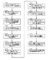
図23は、本発明によるサーマルインターフェース・パッドを組み立てる方法の実施形態の一例を示す流れ図である。ステップ2300において、少なくとも一枚の第1のサーマルインターフェース・プレートを用意する。ステップ2302において、第1のサーマルインターフェース・プレートの少なくとも一枚に、少なくとも1つのエラストマー開口を設ける。ステップ2304において、少なくとも一枚の第2のサーマルインターフェース・プレートを用意する。ステップ2306において、第2のサーマルインターフェース・プレートの少なくとも一枚に、少なくとも1つのエラストマー開口を設ける。オプションのステップ2308において、第1のサーマルインターフェース・プレートと第2のサーマルインターフェース・プレートに、少なくとも1つの第1の開口を設ける。オプションのステップ2310において、第1のサーマルインターフェース・プレートと第2のサーマルインターフェース・プレートに、少なくとも1つの第2の開口を設ける。ステップ2312において、第2のサーマルインターフェース・プレートを、第1のサーマルインターフェース・プレートに対して、約180度、回す。ステップ2314において、第1のサーマルインターフェース・プレートと第2のサーマルインターフェース・プレートを交互に積み重ねる。オプションのステップ2316において、第1の開口と第2の開口に、少なくとも一本のロッドを差し込む。オプションのステップ2318において、少なくとも一本のロッドの端部に、少なくとも一個のばねを配置する。このばねは、スタックされたサーマルインターフェース・プレートに対して、ロッドの軸方向に沿って押圧力を与えるためのものである。オプションのステップ2320において、少なくとも一個のナットを少なくとも一本のロッドにねじ込んで、必要に応じて締め付けて、プレートのスタックへの圧縮力(ロッドの軸方向に沿う力)を生み出す。ステップ2322において、このプレートのスタックを、発熱する装置と熱吸収装置との間に入れる。
FIG. 23 is a flowchart illustrating an example of an embodiment of a method of assembling a thermal interface pad according to the present invention. In
本発明の上の説明は、図示と説明を目的として提示された。すべてを網羅して開示されるものではないし、本発明を、開示されている通りの形態に限定するものでもなく、上述の教示に照らして、他の変更や変形が可能である場合もある。これらの実施形態は、本発明の原理、および本発明の実際の応用をもっともよく説明し、それにより、考えられる特定の用途に適した様々な実施形態および様々な変更例において、他の当業者が本発明を最適に利用できるようにするために、選択され、記述された。併記の特許請求の範囲は、従来技術で限定される範囲を除き、本発明の他の代替実施形態を含むものと解されるべきである。 The above description of the present invention has been presented for purposes of illustration and description. It is not intended to be exhaustive or to limit the invention to the precise form disclosed, and other modifications and variations may be possible in light of the above teachings. These embodiments best explain the principles of the invention and the actual application of the invention, so that, in various embodiments and various modifications suitable for the particular application envisioned, other skilled artisans will appreciate. Have been selected and described in order to make optimal use of the invention. It is intended that the appended claims be construed to include other alternative embodiments of the invention except insofar as limited by the prior art.
300、400、500、700、1100、1300、1800、1900、2000、2100、2200 … サーマルインターフェース・プレート
306、314、404、410、506、514、706、714、1104、1110、1304、1802、1902、2002、2104、2108、2202、2208 … 第1の開口
308、316、406、412、508、516、708、716、1106、1112、1306、1804、1904、2004、2110、2106、2204、2210 … 第2の開口
302、502、702 … 切り欠き
304、312、504、512、704、712 … ばね
402、408、1102、1108 … ばね部材
518、520、718、7201114、1116 … 出張り
1302 … 切り欠き 1308 … エラストマー熱伝導体
1806、1906、2006 … 第1のエラストマー開口
1808、1908、2008 … 第2のエラストマー開口
2206 … エラストマー開口
2112 … 第1のエラストマー 2114 … 第2のエラストマー
2212 … エラストマー
300, 400, 500, 700, 1100, 1300, 1800, 1900, 2000, 2100, 2200 ...
Claims (10)
少なくとも1つの第2のサーマルインターフェース・プレート・アセンブリと、
を備え、
前記第2のサーマルインターフェース・プレート・アセンブリは、前記第1のサーマルインターフェース・プレート・アセンブリと交互に積み重ねられ、
前記第2のサーマルインターフェース・プレート・アセンブリは、前記第2のサーマルインターフェース・プレート・アセンブリの平面内で、前記第1のサーマルインターフェース・プレート・アセンブリに対して約180度、回され、
前記第1および第2のサーマルインターフェース・プレート・アセンブリはそれぞれ、
ばねを1つの側縁に沿って取付け可能に構成されたサーマルインターフェース・プレートと、
前記サーマルインターフェース・プレートの延在方向にほぼ沿って作用する力を外部物体に加えるように構成され、かつ前記サーマルインターフェース・プレートの1つの側縁に取り付けられたばねと、
を具備することを特徴とするサーマルインターフェース・パッド。 At least one first thermal interface plate assembly;
At least one second thermal interface plate assembly;
With
The second thermal interface plate assembly is alternately stacked with the first thermal interface plate assembly;
The second thermal interface plate assembly is rotated about 180 degrees relative to the first thermal interface plate assembly in a plane of the second thermal interface plate assembly;
The first and second thermal interface plate assemblies each include:
A thermal interface plate configured to allow a spring to be mounted along one side edge;
A spring configured to apply a force acting on the external object substantially along a direction in which the thermal interface plate extends, and attached to one side edge of the thermal interface plate;
A thermal interface pad comprising:
少なくとも1つの第2のサーマルインターフェース・プレート・アセンブリと、
を備え、
前記第2のサーマルインターフェース・プレート・アセンブリは、前記第1のサーマルインターフェース・プレート・アセンブリと交互に積み重ねられ、
前記第2のサーマルインターフェース・プレート・アセンブリは、前記第2のサーマルインターフェース・プレート・アセンブリの平面内で、前記第1のサーマルインターフェース・プレート・アセンブリに対して約180度、回され、
前記サーマルインターフェース・プレート・アセンブリはそれぞれ、
弾性を有する熱伝導体を1つの側縁に沿って取付け可能に構成された切欠きを有するサーマルインターフェース・プレートと、
前記サーマルインターフェース・プレートの延在方向にほぼ沿って作用する力を外部物体に加えるように構成され、かつ前記サーマルインターフェース・プレートの1つの側縁に取り付けられた弾性を有する熱伝導体と、
を具備することを特徴とするサーマルインターフェース・パッド。 At least one first thermal interface plate assembly;
At least one second thermal interface plate assembly;
With
The second thermal interface plate assembly is alternately stacked with the first thermal interface plate assembly;
The second thermal interface plate assembly is rotated about 180 degrees relative to the first thermal interface plate assembly in a plane of the second thermal interface plate assembly;
Each of the thermal interface plate assemblies is
A thermal interface plate having a notch configured to allow an elastic heat conductor to be attached along one side edge;
An elastic thermal conductor configured to apply a force acting on an external object substantially along a direction in which the thermal interface plate extends, and attached to one side edge of the thermal interface plate;
A thermal interface pad comprising:
少なくとも1つの第2のサーマルインターフェース・プレート・アセンブリと、
を備え、
前記第2のサーマルインターフェース・プレート・アセンブリは、前記第1のサーマルインターフェース・プレート・アセンブリと交互に積み重ねられ、
前記第2のサーマルインターフェース・プレート・アセンブリは、前記第2のサーマルインターフェース・プレート・アセンブリの平面内で、前記第1のサーマルインターフェース・プレート・アセンブリに対して約180度、回され、
前記サーマルインターフェース・プレート・アセンブリはそれぞれ、
少なくとも1つのばね作用を有する機構を1つの側縁に沿って取付け可能に構成されたサーマルインターフェース・プレートと、
前記サーマルインターフェース・プレートの延在方向にほぼ沿って作用する力を外部物体に加えるように構成され、かつ前記サーマルインターフェース・プレートの1つの側縁に取り付けられた少なくとも1つのばね作用を有する機構と、
を具備することを特徴とするサーマルインターフェース・パッド。 At least one first thermal interface plate assembly;
At least one second thermal interface plate assembly;
With
The second thermal interface plate assembly is alternately stacked with the first thermal interface plate assembly;
The second thermal interface plate assembly is rotated about 180 degrees relative to the first thermal interface plate assembly in a plane of the second thermal interface plate assembly;
Each of the thermal interface plate assemblies is
A thermal interface plate configured to attach at least one spring-acting mechanism along one side edge;
At least one spring-acting mechanism configured to apply a force acting on the external object substantially along the direction of extension of the thermal interface plate and attached to one side edge of the thermal interface plate; ,
A thermal interface pad comprising:
少なくとも1つの第2のサーマルインターフェース・プレート・アセンブリと、
を備え、
前記第2のサーマルインターフェース・プレート・アセンブリは、前記第1のサーマルインターフェース・プレート・アセンブリと交互に積み重ねられ、
前記第2のサーマルインターフェース・プレート・アセンブリは、前記第2のサーマルインターフェース・プレート・アセンブリの平面内で、前記第1のサーマルインターフェース・プレート・アセンブリに対して約180度、回され、
前記サーマルインターフェース・プレート・アセンブリはそれぞれ、
前記サーマルインターフェース・プレートの延在方向にほぼ沿う力を外部物体に加えるように構成され、かつ前記サーマルインターフェース・プレートの1つの側縁に沿って少なくとも1つのばね作用を有する機構を含むサーマルインターフェース・プレートを具備することを特徴とするサーマルインターフェース・パッド。 At least one first thermal interface plate assembly;
At least one second thermal interface plate assembly;
With
The second thermal interface plate assembly is alternately stacked with the first thermal interface plate assembly;
The second thermal interface plate assembly is rotated about 180 degrees relative to the first thermal interface plate assembly in a plane of the second thermal interface plate assembly;
Each of the thermal interface plate assemblies is
A thermal interface including a mechanism configured to apply a force to an external object substantially along a direction in which the thermal interface plate extends, and including at least one spring-acting mechanism along one side edge of the thermal interface plate. A thermal interface pad comprising a plate.
少なくとも1つの第2のサーマルインターフェース・プレート・アセンブリと、
少なくとも1つの弾性体と、
を備え、
前記第2のサーマルインターフェース・プレート・アセンブリは、前記第1のサーマルインターフェース・プレート・アセンブリと交互に積み重ねられ、
前記第2のサーマルインターフェース・プレート・アセンブリは、前記第2のサーマルインターフェース・プレート・アセンブリの平面内で、前記第1のサーマルインターフェース・プレート・アセンブリに対して約180度、回され、
前記サーマルインターフェース・プレート・アセンブリはそれぞれ、前記弾性体を取付け可能に構成された少なくとも1つの弾性体用開口を含むサーマルインターフェース・プレートを具備することを特徴とするサーマルインターフェース・パッド。 At least one first thermal interface plate assembly;
At least one second thermal interface plate assembly;
At least one elastic body;
With
The second thermal interface plate assembly is alternately stacked with the first thermal interface plate assembly;
The second thermal interface plate assembly is rotated about 180 degrees relative to the first thermal interface plate assembly in a plane of the second thermal interface plate assembly;
The thermal interface pad, wherein each of the thermal interface plate assemblies includes a thermal interface plate including at least one elastic body opening configured to be capable of mounting the elastic body.
少なくとも一枚の第1のサーマルインターフェース・プレートを用意することと、
少なくとも一個のばねを、前記第1のサーマルインターフェース・プレートの少なくとも一枚に取り付けることと、
少なくとも一枚の第2のサーマルインターフェース・プレートを用意することと、
少なくとも一個のばねを、前記第2のサーマルインターフェース・プレートの少なくとも一枚に取り付けることと、
前記第2のサーマルインターフェース・プレートを、前記第2のサーマルインターフェース・プレート・アセンブリの平面内で、前記第1のサーマルインターフェース・プレート・アセンブリに対して約180度、回すことと、
前記第1のサーマルインターフェース・プレートと前記第2のサーマルインターフェース・プレートを交互に積み重ねることと、
前記サーマルインターフェース・プレートのスタックを、発熱する装置と熱吸収装置との間に入れることと、
を有することを特徴とする方法。 A method of assembling thermal interface pads,
Providing at least one first thermal interface plate;
Attaching at least one spring to at least one of said first thermal interface plates;
Providing at least one second thermal interface plate;
Attaching at least one spring to at least one of said second thermal interface plates;
Rotating the second thermal interface plate about 180 degrees relative to the first thermal interface plate assembly in the plane of the second thermal interface plate assembly;
Alternately stacking said first thermal interface plate and said second thermal interface plate;
Placing the stack of thermal interface plates between a heat generating device and a heat absorbing device;
A method comprising:
少なくとも一枚の第1のサーマルインターフェース・プレートを用意することと、
少なくとも1つのばね部材を、前記第1のサーマルインターフェース・プレートの少なくとも一枚に取り付けることと、
少なくとも一枚の第2のサーマルインターフェース・プレートを用意することと、
少なくとも1つのばね部材を、前記第2のサーマルインターフェース・プレートの少なくとも一枚に取り付けることと、
前記第2のサーマルインターフェース・プレートを、前記第2のサーマルインターフェース・プレート・アセンブリの平面内で、前記第1のサーマルインターフェース・プレート・アセンブリに対して約180度、回すことと、
前記第1のサーマルインターフェース・プレートと前記第2のサーマルインターフェース・プレートを交互に積み重ねることと、
前記サーマルインターフェース・プレートのスタックを、発熱する装置と熱吸収装置との間に入れることと、
を有することを特徴とする方法。 A method of assembling thermal interface pads,
Providing at least one first thermal interface plate;
Attaching at least one spring member to at least one of said first thermal interface plates;
Providing at least one second thermal interface plate;
Attaching at least one spring member to at least one of said second thermal interface plates;
Rotating the second thermal interface plate about 180 degrees relative to the first thermal interface plate assembly in the plane of the second thermal interface plate assembly;
Alternately stacking said first thermal interface plate and said second thermal interface plate;
Placing the stack of thermal interface plates between a heat generating device and a heat absorbing device;
A method comprising:
少なくとも一枚が少なくとも1つのばね部材を含む第1のサーマルインターフェース・プレートを少なくとも1つ用意することと、
少なくとも一枚が少なくとも1つのばね部材を含む第2のサーマルインターフェース・プレートを少なくとも1つ用意することと、
前記第2のサーマルインターフェース・プレートを、前記第2のサーマルインターフェース・プレート・アセンブリの平面内で、前記第1のサーマルインターフェース・プレート・アセンブリに対して約180度、回すことと、
前記第1のサーマルインターフェース・プレートと前記第2のサーマルインターフェース・プレートを交互に積み重ねることと、
前記サーマルインターフェース・プレートのスタックを、発熱する装置と熱吸収装置との間に入れることと、
を有することを特徴とする方法。 A method of assembling thermal interface pads,
Providing at least one first thermal interface plate, at least one of which includes at least one spring member;
Providing at least one second thermal interface plate, at least one of which includes at least one spring member;
Rotating the second thermal interface plate about 180 degrees relative to the first thermal interface plate assembly in the plane of the second thermal interface plate assembly;
Alternately stacking said first thermal interface plate and said second thermal interface plate;
Placing the stack of thermal interface plates between a heat generating device and a heat absorbing device;
A method comprising:
少なくとも一枚の第1のサーマルインターフェース・プレートを用意することと、
前記少なくとも一枚の第1のサーマルインターフェース・プレートの1つの側縁に沿って、切欠きを設けることと、
少なくとも1つの弾性を有する熱伝導体を、前記第1のサーマルインターフェース・プレートの少なくとも一枚に、前記切欠きに沿って取り付けることと、
少なくとも一枚の第2のサーマルインターフェース・プレートを用意することと、
前記少なくとも一枚の第2のサーマルインターフェース・プレートの1つの側縁に沿って、切欠きを設けることと、
少なくとも1つの弾性を有する熱伝導体を、前記第2のサーマルインターフェース・プレートの少なくとも一枚に、前記切欠きに沿って取り付けることと、
前記第2のサーマルインターフェース・プレートを、前記第2のサーマルインターフェース・プレート・アセンブリの平面内で、前記第1のサーマルインターフェース・プレート・アセンブリに対して約180度、回すことと、
前記第1のサーマルインターフェース・プレートと前記第2のサーマルインターフェース・プレートを交互に積み重ねることと、
前記サーマルインターフェース・プレートのスタックを、発熱する装置と熱吸収装置との間に入れることと、
を有することを特徴とする方法。 A method of assembling thermal interface pads,
Providing at least one first thermal interface plate;
Providing a notch along one side edge of the at least one first thermal interface plate;
Attaching at least one elastic thermal conductor to at least one of the first thermal interface plates along the notch;
Providing at least one second thermal interface plate;
Providing a notch along one side edge of the at least one second thermal interface plate;
Attaching at least one resilient thermal conductor to at least one of the second thermal interface plates along the notch;
Rotating the second thermal interface plate about 180 degrees relative to the first thermal interface plate assembly in the plane of the second thermal interface plate assembly;
Alternately stacking said first thermal interface plate and said second thermal interface plate;
Placing the stack of thermal interface plates between a heat generating device and a heat absorbing device;
A method comprising:
少なくとも一枚の第1のサーマルインターフェース・プレートを用意することと、
前記第1のサーマルインターフェース・プレートの少なくとも一枚に、少なくとも1つの弾性体用開口を設けることと、
少なくとも一枚の第2のサーマルインターフェース・プレートを用意することと、
前記第2のサーマルインターフェース・プレートの少なくとも一枚に、少なくとも1つの弾性体用開口を設けることと、
前記第2のサーマルインターフェース・プレートを、前記第2のサーマルインターフェース・プレート・アセンブリの平面内で、前記第1のサーマルインターフェース・プレート・アセンブリに対して約180度、回すことと、
前記第1のサーマルインターフェース・プレートと前記第2のサーマルインターフェース・プレートを交互に積み重ねることと、
弾性体を、前記弾性体用開口を通じて、前記第1のサーマルインターフェース・プレートと前記第2のサーマルインターフェース・プレートに入れることと、
前記サーマルインターフェース・プレートのスタックを、発熱する装置と熱吸収装置との間に入れることと、
を有することを特徴とする方法。
A method of assembling thermal interface pads,
Providing at least one first thermal interface plate;
Providing at least one elastic body opening in at least one of the first thermal interface plates;
Providing at least one second thermal interface plate;
Providing at least one elastic body opening in at least one of the second thermal interface plates;
Rotating the second thermal interface plate about 180 degrees relative to the first thermal interface plate assembly in the plane of the second thermal interface plate assembly;
Alternately stacking said first thermal interface plate and said second thermal interface plate;
Inserting an elastic body into the first thermal interface plate and the second thermal interface plate through the elastic body opening;
Placing the stack of thermal interface plates between a heat generating device and a heat absorbing device;
A method comprising:
Applications Claiming Priority (1)
| Application Number | Priority Date | Filing Date | Title |
|---|---|---|---|
| US10/283,907 US6910271B2 (en) | 2002-10-29 | 2002-10-29 | Mechanical highly compliant thermal interface pad |
Publications (2)
| Publication Number | Publication Date |
|---|---|
| JP2004153267A true JP2004153267A (en) | 2004-05-27 |
| JP2004153267A5 JP2004153267A5 (en) | 2006-09-07 |
Family
ID=32107567
Family Applications (1)
| Application Number | Title | Priority Date | Filing Date |
|---|---|---|---|
| JP2003359658A Withdrawn JP2004153267A (en) | 2002-10-29 | 2003-10-20 | Thermal interface pad having sufficient mechanical flexibility |
Country Status (2)
| Country | Link |
|---|---|
| US (2) | US6910271B2 (en) |
| JP (1) | JP2004153267A (en) |
Families Citing this family (5)
| Publication number | Priority date | Publication date | Assignee | Title |
|---|---|---|---|---|
| US6910271B2 (en) * | 2002-10-29 | 2005-06-28 | Hewlett-Packard Development Company, L.P. | Mechanical highly compliant thermal interface pad |
| US20090208722A1 (en) * | 2008-02-18 | 2009-08-20 | John Francis Timmerman | Oriented Members for Thermally Conductive Interface Structures |
| US9791501B2 (en) * | 2012-09-24 | 2017-10-17 | Intel Corporation | Compliant thermal contact device and method |
| US11486661B2 (en) * | 2020-05-28 | 2022-11-01 | Te Connectivity Solutions Gmbh | Thermal bridge for an electrical component |
| US11240934B1 (en) * | 2020-07-22 | 2022-02-01 | TE Connectivity Services Gmbh | Thermal bridge for an electrical component |
Family Cites Families (11)
| Publication number | Priority date | Publication date | Assignee | Title |
|---|---|---|---|---|
| US4263965A (en) * | 1980-01-21 | 1981-04-28 | International Business Machines Corporation | Leaved thermal cooling module |
| US4498530A (en) * | 1981-08-03 | 1985-02-12 | International Business Machines Corporation | Flexible thermal conduction element for cooling semiconductor devices |
| US4535841A (en) * | 1983-10-24 | 1985-08-20 | International Business Machines Corporation | High power chip cooling device and method of manufacturing same |
| USRE35721E (en) * | 1983-12-14 | 1998-02-03 | Hitachi, Ltd. | Cooling device of semiconductor chips |
| US5052481A (en) * | 1988-05-26 | 1991-10-01 | International Business Machines Corporation | High conduction cooling module having internal fins and compliant interfaces for vlsi chip technology |
| JP2675173B2 (en) * | 1990-03-02 | 1997-11-12 | 株式会社日立製作所 | Electronic device cooling system |
| US5014117A (en) * | 1990-03-30 | 1991-05-07 | International Business Machines Corporation | High conduction flexible fin cooling module |
| US5201866A (en) * | 1992-02-03 | 1993-04-13 | International Business Machines Corporation | Structure for dissipation of heat having slidably engaged fins for conformal disposition against a heat generating surface |
| JPH0786471A (en) * | 1993-09-20 | 1995-03-31 | Hitachi Ltd | Semiconductor module |
| JP2926537B2 (en) * | 1994-12-15 | 1999-07-28 | 株式会社日立製作所 | Multi-chip module cooling system |
| US6910271B2 (en) * | 2002-10-29 | 2005-06-28 | Hewlett-Packard Development Company, L.P. | Mechanical highly compliant thermal interface pad |
-
2002
- 2002-10-29 US US10/283,907 patent/US6910271B2/en not_active Expired - Lifetime
-
2003
- 2003-10-20 JP JP2003359658A patent/JP2004153267A/en not_active Withdrawn
-
2005
- 2005-02-01 US US11/049,346 patent/US7131199B2/en not_active Expired - Lifetime
Also Published As
| Publication number | Publication date |
|---|---|
| US7131199B2 (en) | 2006-11-07 |
| US20040079519A1 (en) | 2004-04-29 |
| US20050132571A1 (en) | 2005-06-23 |
| US6910271B2 (en) | 2005-06-28 |
Similar Documents
| Publication | Publication Date | Title |
|---|---|---|
| US4974119A (en) | Conforming heat sink assembly | |
| US20090213546A1 (en) | Low thermal resistance power module assembly | |
| US20020015288A1 (en) | High performance thermal/mechanical interface for fixed-gap references for high heat flux and power semiconductor applications | |
| US7990717B2 (en) | Heat sink and electronic device using same | |
| JP2009231757A (en) | Radiation member and circuit substrate device | |
| WO2018146933A1 (en) | Semiconductor device and method for manufacturing semiconductor device | |
| US10054375B2 (en) | Self-adjusting cooling module | |
| JP2012227472A (en) | Electronic component mounting structure | |
| JP2011091088A (en) | Heat radiation structure of heating element and semiconductor device using the heat radiation structure | |
| JP5069876B2 (en) | Semiconductor module and heat sink | |
| CN109168288B (en) | Radiator and electronic product | |
| US7131199B2 (en) | Mechanical highly compliant thermal interface pad | |
| WO2014140098A1 (en) | Heat spreader with flat pipe cooling element | |
| JP5640616B2 (en) | Heat dissipation structure for electronic components | |
| JP2002064168A (en) | Cooling device, manufacturing method of cooling device, and semiconductor device | |
| CN109887894B (en) | Heat sink, circuit board and computing device | |
| US6988533B2 (en) | Method and apparatus for mounting a heat transfer apparatus upon an electronic component | |
| JP2010021241A (en) | Thermoelectric conversion device | |
| JPH0864731A (en) | Heat conducting member and cooler and electronic apparatus employing the same | |
| JP6501925B2 (en) | Radiator and method of assembling the same | |
| JP6873157B2 (en) | How to manufacture a thermal block assembly, an LED device with it, and a thermal block assembly | |
| JP2010021410A (en) | Thermo-module | |
| JPH08162680A (en) | Thermo-electric converter | |
| JP4795103B2 (en) | Thermo module and manufacturing method thereof | |
| JP3207656U (en) | Assembly structure of high power semiconductor and radiator |
Legal Events
| Date | Code | Title | Description |
|---|---|---|---|
| A521 | Written amendment |
Free format text: JAPANESE INTERMEDIATE CODE: A523 Effective date: 20060724 |
|
| A621 | Written request for application examination |
Free format text: JAPANESE INTERMEDIATE CODE: A621 Effective date: 20060724 |
|
| A761 | Written withdrawal of application |
Free format text: JAPANESE INTERMEDIATE CODE: A761 Effective date: 20080331 |