JP2004136397A - Water jet processing equipment - Google Patents
Water jet processing equipment Download PDFInfo
- Publication number
- JP2004136397A JP2004136397A JP2002303005A JP2002303005A JP2004136397A JP 2004136397 A JP2004136397 A JP 2004136397A JP 2002303005 A JP2002303005 A JP 2002303005A JP 2002303005 A JP2002303005 A JP 2002303005A JP 2004136397 A JP2004136397 A JP 2004136397A
- Authority
- JP
- Japan
- Prior art keywords
- water
- workpiece
- nozzle
- water jet
- processing
- Prior art date
- Legal status (The legal status is an assumption and is not a legal conclusion. Google has not performed a legal analysis and makes no representation as to the accuracy of the status listed.)
- Pending
Links
Images

Landscapes
- Dicing (AREA)
Abstract
【課題】加工作業を停止した後にノズル内に溜まっている砥粒が混入された加工水を排出し、砥粒による噴射孔の目詰まりを防止することができるウォータージェット加工装置を提供する。
【解決手段】被加工物を保持する被加工物保持機構と、該被加工物保持機構に保持された被加工物にウォータージェットを噴射するノズルと、該ノズルに砥粒を混入した高圧の加工水を供給する加工水供給手段とを具備するウォータージェット加工装置であって、ノズルに清浄水を供給する清浄水供給手段を備えている。
【選択図】 図1To provide a water jet processing apparatus capable of discharging processing water mixed with abrasive particles accumulated in a nozzle after stopping a processing operation and preventing clogging of an injection hole by the abrasive particles.
A workpiece holding mechanism for holding a workpiece, a nozzle for jetting a water jet to the workpiece held by the workpiece holding mechanism, and high-pressure processing in which abrasive grains are mixed into the nozzle A water jet processing apparatus comprising: a processing water supply unit for supplying water; and a clean water supply unit for supplying clean water to a nozzle.
[Selection diagram] Fig. 1
Description
【0001】
【発明の属する技術分野】
本発明は、半導体ウエーハ等の被加工物を高圧のウォータージェットを噴射して切断するウォータージェット加工装置に関する。
【0002】
【従来の技術】
半導体デバイス製造工程においては、略円板形状である半導体ウエーハの表面に格子状に配列された多数の領域にIC、LSI等の回路を形成し、該回路が形成された各領域を所定のストリートといわれる切断ラインに沿ってダイシングすることにより個々の半導体チップを製造している。このようにして分割された半導体チップは、パッケージングされて携帯電話やパソコン等の電気機器に広く利用されている。
携帯電話やパソコン等の電気機器はより軽量化、小型化が求められており、半導体チップのパッケージもチップサイズパッケージ(CSP)と称する小型化できるパッケージ技術が開発されている。CSP技術の一つとして、Quad Flat Non−lead Package(QFN)と称するパッケージ技術が実用化されている。このQFNと称するパッケージ技術は、半導体チップの接続端子に対応した接続端子が複数形成されているとともに半導体チップ毎に区画するストリートが格子状に形成された銅板等の金属板に複数個の半導体チップをマトリックス状に配設し、半導体チップの裏面側から樹脂をモールディングした樹脂部によって金属板と半導体チップを一体化することによりCSP基板を形成する。このCSP基板をストリートに沿って切断することにより、個々にパッケージされたチップサイズパッケージ(CSP)に分割する。
【0003】
上記CSP基板の切断は、一般にダイシング装置とよばれる精密切削装置によって施される。このダイシング装置は、環状の砥粒層を備えた切削ブレードを備え、この切削ブレードを回転させつつCSP基板のストリートに沿って相対移動することにより、CSP基板をストリートに沿って切削し、個々のCSPに分割する。しかるに、CSP基板を切削ブレードによって切断すると、接続端子にバリが生じ、隣接する接続端子同士が短絡してチップサイズパッケージ(CSP)の品質および信頼性を低下させるという問題がある。
【0004】
また、CSP基板に限らず、半導体ウエーハ等の被加工物を切削ブレードによって切削すると、被加工物の表面に微細な切削屑が付着して汚染するという問題もある。
このような切削ブレードによる切断における問題を解消する切断技術として、被加工物保持機構によって保持された被加工物にシリカやガーネット等の砥粒を混入した高圧のウォータージェットをノズルから噴射して被加工物を切断するウォータージェット切断加工が提案されている。(例えば、特許文献1参照。)
【0005】
【特許文献1】
特開平2002−205298号公報
【0006】
【発明が解決しようとする課題】
而して、ウォータージェット加工装置の稼働を停止して暫く放置すると、ノズル内に溜まっている加工水に混入された砥粒が沈殿して噴射孔を塞ぎ、次に使用する際にノズルの噴射孔が詰まって使用不可能となるという問題がある。
【0007】
本発明は上記事実に鑑みてなされたものであり、その主たる技術的課題は、加工作業を停止した後にノズル内に溜まっている砥粒が混入された加工水を排出し、砥粒による噴射孔の目詰まりを防止することができるウォータージェット加工装置を提供することである。
【0008】
【課題を解決するための手段】
上記主たる技術課題を解決するため、本発明によれば、被加工物を保持する被加工物保持機構と、該被加工物保持機構に保持された被加工物にウォータージェットを噴射するノズルと、該ノズルに砥粒を混入した高圧の加工水を供給する加工水供給手段と、を具備するウォータージェット加工装置において、
該ノズルに清浄水を供給する清浄水供給手段を備えている、
ことを特徴とするウォータージェット加工装置が提供される。
【0009】
【発明の実施の形態】
以下、本発明に従って構成されたウォータージェット加工装置の好適実施形態を図示している添付図面を参照して、更に詳細に説明する。
【0010】
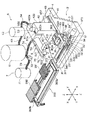
図1には、本発明に従って構成されたウォータージェット加工装置の一部を分解した斜視図が示されている。図1に示されたウォータージェット加工装置は、静止基台2と、該静止基台2に矢印Xで示す切断送り方向に移動可能に配設され被加工物を保持する被加工物保持機構3と、静止基台2に上記矢印Xで示す方向と直角な矢印Yで示す割り出し方向に移動可能に配設されたウォータージェット噴射ユニット支持機構4と、該ウォータージェット噴射ユニット支持機構4に矢印Zで示す方向に移動可能に配設されたウォータージェット噴射ユニット5を具備している。
【0011】
上記被加工物保持機構3は、静止基台2上に矢印Xで示す方向に沿って平行に配設された一対の案内レール31、31と、該案内レール31、31上に矢印Xで示す方向に移動可能に配設された第一の滑動ブロック32と、該第1の滑動ブロック32上に矢印Yで示す方向に移動可能に配設された第2の滑動ブロック33と、該第2の滑動ブロック33上に円筒部材34によって支持された支持テーブル35と、ベーステーブル36を具備している。ベーステーブル36は、円筒部材34内を挿通して配設された回転軸340の上端に取り付けられており、円筒部材34内に配設された図示しないパルスモータによってウォータージェット噴射ユニット5の後述するノズルから噴射されるウォータージェットの方向に対して直角な面内、即ち水平面内で回転せしめられるように構成されている。このベーステーブル36に被加工物を着脱可能に位置付ける着脱テーブルが載置され保持される。以下、ベーステーブル36および着脱テーブルについて、図2乃至図4を参照して説明する。
【0012】
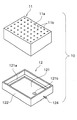
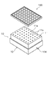
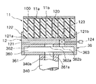
図2は着脱テーブル10を分解して示す斜視図、図3は着脱テーブル10と被加工物としてのCSP基板100を示す斜視図、図4は着脱テーブル10をベーステーブル36に保持した状態を示す断面図である。
先ず、ベーステーブル36について図4および図1を参照して説明する。
図示の実施形態におけるベーステーブル36は、底壁361と上壁362および枠状の側壁363からなる矩形状に形成され、これら各壁によって形成された負圧室360を備えている。ベーステーブル36を構成する底壁361の中央部には、負圧室360と回転軸340に設けられた通路340aと連通する負圧導入穴361a形成されている。なお、回転軸340に設けられた通路340aは、図示しない負圧制御回路を介して吸引源に連通されている。ベーステーブル36を構成する上壁362には、負圧室360と連通し載置面となる上面に開口する吸引口362aと連通穴362bが設けられている。吸引口362aは中央部に形成されており、連通穴362bは吸引口362aの図4において右側に形成されている。
【0013】
図示の実施形態における着脱テーブル10は、図2に示すように直方体状の緩和部材11と、該緩和部材11を保持する保持トレー12とからなっている。緩和部材11は、図示の実施形態においてはウレタンによって形成されており、上面が被加工物を支持する支持面11aとなっている。なお、緩和部材11を構成する材料としては、ウレタン等の樹脂の外、ステンレス鋼、タングステン、ニッケル、銅等の金属、アルミナ等のセラミックスを用いることができる。緩和部材11には、上面である支持面11aに開口するとともに下面に貫通する複数個の吸引孔11bが設けられている。この吸引孔11bは、支持面11aにおける被加工物が分割される個々のチップと対向する位置に形成されている。
【0014】
着脱テーブル10を構成する保持トレー12は、図2に示すように矩形状の底壁121と、該底壁121の周縁から上方に突出して形成された枠状の側壁122とからなり、上方が開放されている。なお、保持トレー12は、ステンレス鋼等の金属材によって構成されている。保持トレー12を構成する底壁121の上面周辺には、上記緩和部材11の下面を載置支持する枠状の支持棚121aが形成されている。また、保持トレー12を構成する底壁121には、上記ベーステーブル36を構成する上壁362に設けられた連通穴362bと対応する位置に連通穴121bが形成されている。この連通穴121bには、図4に示すように逆止弁123が配設されている。この逆止弁123は、ベーステーブル36の負圧室360側の負圧が大きいときは流通を許容するが、保持トレー12内の負圧が大きいときは流通を遮断する。即ち、逆止弁123は、保持トレー12内への負圧の流入は許容するが、保持トレー12内の負圧の流出は遮断する。逆止弁123に関連して、保持トレー12を構成する底壁121には、逆止弁123の機能を開放する作動ロッド124が配設されている。このように構成された保持トレー12に、図3および図4に示すように上方開口側から上記緩和部材11の下部が嵌合される。この嵌合状態においては、緩和部材11の下面周辺部が保持トレー12を構成する底壁121に形成された枠状の支持棚121a上に載置される。このため、図4に示すように底壁121の上面と緩和部材11の下面との間には吸引室120が形成される。この結果、緩和部材11に形成された複数個の吸引孔11bは、吸引室120と連通する。
【0015】
上記のように構成された着脱テーブル10は、緩和部材11の上面である支持面11aにCSP基板等の被加工物100を載置し、図4に示すようにベーステーブル36の載置面となる上面に載置される。このようにして、緩和部材11の支持面11aに被加工物100を支持した着脱テーブル10がベーステーブル36に載置されたならば、図示しない負圧制御回路を制御して回転軸340に設けられた通路340aを図示しない吸引源に連通すると、ベーステーブル36の底壁361に設けられた負圧導入穴361a、負圧室360、ベーステーブル36の上壁362に設けられた吸引口362aを通して着脱テーブル10を構成する保持トレー12の下面に負圧が作用し、保持トレー12がベーステーブル36に吸引保持される。一方、上記のようにしてベーステーブル36の負圧室360が吸引源に連通されると、ベーステーブル36の上壁362に設けられた連通穴362b、保持トレー12の底壁121に設けられた連通穴121bに配設された逆止弁123、吸引室120、緩和部材11に設けられた吸引孔11bを通して被加工物100の下面に負圧が作用し、被加工物100が緩和部材11に吸引保持される。
【0016】
図1に戻って、説明を続けると、上記第1の滑動ブロック32は、その下面に上記一対の案内レール31、31と嵌合する一対の被案内溝321、321が設けられているとともに、その上面に矢印Yで示す方向に沿って平行に形成された一対の案内レール322、322が設けられている。このように構成された第1の滑動ブロック32は、被案内溝321、321が一対の案内レール31、31に嵌合することにより、一対の案内レール31、31に沿って矢印Xで示す方向に移動可能に構成される。図示の実施形態における被加工物保持機構3は、第1の滑動ブロック32を一対の案内レール31、31に沿って矢印Xで示す方向に移動させるための第1の移動手段37を具備している。第1の移動手段37は、上記一対の案内レール31と31の間に平行に配設された雄ネジロッド371と、該雄ネジロッド371を回転駆動するためのパルスモータ372等の駆動源を含んでいる。雄ネジロッド371は、その一端が上記静止基台2に固定された軸受ブロック373に回転自在に支持されており、その他端が上記パルスモータ372の出力軸に図示しない減速装置を介して伝動連結されている。なお、雄ネジロッド371は、第1の滑動ブロック32の中央部下面に突出して設けられた図示しない雌ネジブロックに形成された貫通雌ネジ穴に螺合されている。従って、パルスモータ372によって雄ネジロッド371を正転および逆転駆動することにより、第一の滑動ブロック32は案内レール31、31に沿ってウォータージェット噴射ユニット5の後述するノズルから噴射されるウォータージェットの方向に対して直角な面内、即ち水平面内において矢印Xで示す方向に移動せしめられる。
【0017】
上記第2の滑動ブロック33は、その下面に上記第1の滑動ブロック32の上面に設けられた一対の案内レール322、322と嵌合する一対の被案内溝331、331が設けられており、この被案内溝331、331を一対の案内レール322、322に嵌合することにより、矢印Yで示す方向に移動可能に構成される。図示の実施形態における被加工物保持機構3は、第2の滑動ブロック33を第1の滑動ブロック32に設けられた一対の案内レール322、322に沿って矢印Yで示す方向に移動させるための第2の移動手段38を具備している。第2の移動手段38は、上記一対の案内レール322と322の間に平行に配設された雄ネジロッド381と、該雄ネジロッド381を回転駆動するためのパルスモータ382等の駆動源を含んでいる。雄ネジロッド381は、その一端が上記第1の滑動ブロック32の上面に固定された軸受ブロック383に回転自在に支持されており、その他端が上記パルスモータ382の出力軸に図示しない減速装置を介して伝動連結されている。なお、雄ネジロッド381は、第2の滑動ブロック33の中央部下面に突出して設けられた図示しない雌ネジブロックに形成された貫通雌ネジ穴に螺合されている。従って、パルスモータ382によって雄ネジロッド381を正転および逆転駆動することにより、第2の滑動ブロック33は案内レール322、322に沿って矢印Xと直角な矢印Yで示す割り出し送り方向に移動せしめられる。
【0018】
上記支持テーブル35の矢印Xで示す方向の両側には蛇腹手段391、392が配設されており、被加工物保持機構3を構成するベーステーブル36以外の各構成部材は蛇腹手段391、392によって覆われている。この蛇腹手段391、392は、対向する端部がそれぞれ支持テーブル35に取り付けられる。蛇腹手段391、392の両側端部は、上記被加工物保持機構3を囲撓して静止基台2上に配設される枠状の排水樋手段393の内側端壁393a、393bに取り付けられる。
【0019】
上記ウォータージェット噴射ユニット支持機構4は、静止基台2上に矢印Yで示す割り出し送り方向に沿って平行に配設された一対の案内レール41、41と、該案内レール41、41上に矢印Yで示す方向に移動可能に配設された可動支持基台42を具備している。この可動支持基台42は、案内レール41、41上に移動可能に配設された移動支持部421と、該移動支持部421に取り付けられた装着部422とからなっている。装着部422は、一側面に矢印Zで示す方向に延びる一対の案内レール422a、422aが平行に設けられている。図示の実施形態におけるウォータージェット噴射ユニット支持機構4は、可動支持基台42を一対の案内レール41、41に沿って割り出し送り方向である矢印Yで示す方向に移動させるための第3の移動手段43を具備している。第3の駆動手段43は、上記一対の案内レール41、41の間に平行に配設された雄ネジロッド431と、該雄ねじロッド431を回転駆動するためのパルスモータ432等の駆動源を含んでいる。雄ネジロッド431は、その一端が上記静止基台2に固定された図示しない軸受ブロックに回転自在に支持されており、その他端が上記パルスモータ432の出力軸に図示しない減速装置を介して伝動連結されている。なお、雄ネジロッド431は、可動支持基台42を構成する移動支持部421の中央部下面に突出して設けられた図示しない雌ネジブロックに形成された雌ネジ穴に螺合されている。このため、パルスモータ432によって雄ネジロッド431を正転および逆転駆動することにより、可動支持基台42は案内レール41、41に沿って矢印Yで示す割り出し送り方向に移動せしめられる。
【0020】
図示の実施形態のおけるウォータージェット噴射ユニット5は、ユニットホルダ51と、該ユニットホルダ51に取り付けられたウォータージェット噴射手段52を具備している。ユニットホルダ51は、上記装着部422に設けられた一対の案内レール422a、422aに摺動可能に嵌合する一対の被案内溝51a、51aが設けられており、この被案内溝51a、51aを上記案内レール422a、422aに嵌合することにより、矢印Zで示す方向に移動可能に支持される。図示の実施形態におけるウォータージェット噴射ユニット5は、ユニットホルダ51を一対の案内レール422a、422aに沿って矢印Zで示す方向に移動させるための第4の移動手段53を具備している。第4の移動手段53は、上記第1乃至第3の移動手段と同様に一対案内レール422a、422aの間に配設された雄ネジロッド(図示せず)と、該雄ネジロッドを回転駆動するためのパルスモータ532等の駆動源を含んでおり、パルスモータ532によって図示しない雄ネジロッドを正転および逆転駆動することにより、ユニットホルダ51およびウォータージェット噴射手段52を案内レール422a、422aに沿って矢印Zで示す方向に移動せしめる。
【0021】
上記ウォータージェット噴射手段52は、上記ユニットホルダ51に固定され実質上水平に延出する円筒形状のケーシング521の先端に配設されたノズル522を備えている。ノズル522について、図5を参照して説明する。
図5に示すノズル522は、ノズル本体522aと、該ノズル本体522aに形成された通路522bと、該通路522bと連通し下面に開口する直径が30〜100μmの噴射孔522cとからなっている。このように構成されたノズル522には、ノズル本体522aの上部に通路522bと連通する加工水導入通路522dが設けられているとともに、ノズル本体522aの中間部に通路522bと連通する清浄水導入通路522eが設けられている。加工水導入通路522dには後述する加工水供給手段が接続され、清浄水導入通路522eには後述する清浄水供給手段が接続される。
【0022】
次に、図1を参照して加工水供給手段6および清浄水供給手段7について説明する。
図1に示す加工水供給手段6は、加工水貯留タンク61と高圧水生成手段62を備えている。加工水貯留タンク61は水にシリカ、ガーネット等の微細な砥粒が混入された加工水を収容しており、フレキシブルパイプ63によって高圧水生成手段62に接続されている。高圧水生成手段62は、加工水を300〜500メガパスカル(MPa)に昇圧する。高圧水生成手段62で昇圧された加工水は、フレキシブルパイプ64および円筒形状のケーシング521内に設けられた図示しない通路を通してノズル522の加工水導入通路522dに供給される。
【0023】
図1に示す清浄水供給手段7は、清浄水貯留タンク71と加圧ポンプ72を備えている。清浄水貯留タンク71はノズル522を清掃するための水を収容しており、フレキシブルパイプ73によって加圧ポンプ72に接続されている。加圧ポンプ72によって送り出された水は、フレキシブルパイプ74およびパイプ75を通してノズル522の清浄水導入通路522eに供給される。なお、清浄水導入通路522eとパイプ75との間には、清浄水導入通路522e側からパイプ75側への流通を遮断する逆止弁76が配設されている。
【0024】
上記ウォータージェット噴射手段52を構成するケーシング521の前端部には、撮像手段8が配設されている。この撮像手段8は、CSP基板等の被加工物に形成されたストリート等を撮像するための顕微鏡やCCDカメラ等で構成されており、撮像した画像信号を図示しない制御手段に送る。
【0025】
図示の実施形態におけるウォータージェット加工装置は以上のように構成されており、以下その切断動作について主に図1を参照して説明する。
被加工物保持機構3を構成するベーステーブル36が図1に示す位置に位置付けられた状態で、上述したようにベーステーブル36に着脱テーブル10の保持トレー12を吸引保持するとともに、緩和部材11の支持面11a上に被加工物100を吸引保持する。次に、ベーステーブル36および着脱テーブル10を第1の移動手段37の作動により案内レール31、31に沿って移動せしめ、撮像手段8の直下に位置付ける。
【0026】
上述したようにベーステーブル36および着脱テーブル10が撮像手段58の直下に位置付けられると、撮像手段8および図示しない制御手段によって着脱テーブル10の保持された被加工物100に形成されているストリートと、ストリートに沿ってウォータージェットを噴射するウォータージェット噴射ユニット5のノズル522との位置合わせを行うためのパターンマッチング等の画像処理が実行され、ウォータージェット噴射位置のアライメントが遂行される。
【0027】
上記のようにしてアライメントが行われたならば、ベーステーブル36および着脱テーブル10をウォータージェット噴射ユニット5のノズル522が位置する切削領域に移動し、加工水供給手段6の高圧水生成手段62を作動して、切削領域において被加工物100における上述のようにして検出されたストリートに沿ってノズル522の噴射孔522cから高圧の加工水をウォータージェットとして噴射し、ストリートに沿って切断する。この切断動作時においては、ウォータージェットは被加工物100を切断時に貫通するが、切断後のウォータージェットは着脱テーブル10の緩和部材11に受けられて、その勢いが和らげられる。このウォータージェットの作用によって緩和部材11は次第に損傷するので、所定回数使用したら交換する。なお、切断作用後に勢いが和らげられた水は、蛇腹手段391、392から落下して、枠状の排水樋手段393に流れる。
【0028】
上述したように所定のストリートに沿って切断したら、ベーステーブル36および着脱テーブル10を矢印Yで示す割り出し方向にストリートの間隔だけ割り出し送りし、上記切断動作を遂行する。ベーステーブル36および着脱テーブル10の割り出し送りは、被加工物保持機構3を構成する第2の移動手段38によって行われる。なお、割り出し送りは、ウォータージェット噴射ユニット支持機構を構成する第3の移動手段43によって実行してもよいが、高圧水生成手段62に影響するためベーステーブル36を移動するのが好ましい。このようにして所定方向に延在する全てのストリートについて切断動作と割り出し動作を遂行したならば、ベーステーブル36および着脱テーブル10を90度回動せしめて、上記所定方向に対して垂直に延びる各ストリートに沿って上記切断動作と割り出し動作を実行することにより、着脱テーブル10に保持された被加工物100は個々のチップに分割される。
【0029】
このようにして、被加工物100を個々のチップに分割したら、高圧水生成手段62の作動を停止し、ノズル522の噴射孔522cからの加工水の噴射を停止する。そして、被加工物100を保持している着脱テーブル10およびベーステーブル36は、図1に示す位置に戻され、ここで、着脱テーブル10と吸引源との連通を遮断する。この結果、着脱テーブル10のベーステーブル36への吸引保持が解除される。一方、着脱テーブル10を構成する保持トレー12の底壁121に形成された連通穴121bには逆止弁123が配設されているので、吸引源との連通が遮断されても吸引室120は負圧状態に維持される。この結果、着脱テーブル10による被加工物100の吸引保持は維持される。このとき、被加工物100は個々のチップに分割されているが、緩和部材11に設けられた複数個の吸引孔11bは支持面11aにおける被加工物が分割される個々のチップと対向する位置に形成されているので、チップの状態でも吸引保持は維持される。従って、被加工物100が分割された個々のチップは、着脱テーブル10に吸着保持された状態で所定の場所に搬送することができる。なお、着脱テーブル10に吸着保持された状態で搬送された各チップを取り外す場合には、保持トレー12に配設された作動ロッド124を押して逆止弁123を開放すると、吸引室120内が大気圧となって各チップの吸引保持が解除される。
【0030】
以上のようにして加工作業が終了したら、清浄水供給手段7の給水ポンプ72を作動して1〜10メガパスカル(MPa)の圧力で清浄水をノズル522の清浄水導入通路522eに導入する。この結果、上記加工作業終了時にノズル522の通路522b内に残っている砥粒が混入された加工水は、噴射孔522cを通して清浄水とともに排出されるとともに、清浄水の圧力によって高圧水生成手段62に押し戻される。従って、ノズル522内には清浄水だけが残ることになるので、稼働を停止して放置しても加工水に混入された砥粒が沈殿して噴射孔522cを詰まらせることはない。なお、図示の実施形態においては、清浄水をノズル522に直接導入する例を示したが、清浄水は高圧水生成手段62から加工水供給通路522dまでの経路に導入するようにしてもよい。
【0031】
【発明の効果】
本発明によるウォータージェット加工装置は以上のように構成され、被加工物保持機構に保持された被加工物にウォータージェットを噴射するノズルと、該ノズルに砥粒を混入した高圧の加工水を供給する加工水供給手段を具備するウォータージェット加工装置において、ノズルに清浄水を供給する清浄水供給手段を備えているので、加工作業が終了したら清浄水供給手段を作動して清浄水をノズルに導入することにより、加工作業終了時にノズル内に残っている砥粒が混入された加工水は清浄水とともに排出される。従って、ノズルには清浄水だけが残ることになるので、稼働を停止して放置しても加工水に混入された砥粒が沈殿して噴射孔を詰まらせることはない。
【図面の簡単な説明】
【図1】本発明に従って構成されたウォータージェット加工装置の一部を分解して示す斜視図。
【図2】図1に示すウォータージェット加工装置に用いられる着脱テーブルを構成する緩和部材と保持トレーを分解して示す斜視図。
【図3】図1に示すウォータージェット加工装置に用いられる着脱テーブルと被加工物を示す斜視図。
【図4】図3に示す着脱テーブルをベーステーブルに保持した状態を示す断面図。
【図5】図1に示すウォータージェット加工装置に用いられるウォータージェットを噴射するノズルの断面図。
【符号の説明】
2:静止基台
3:被加工物保持機構
31:案内レール
32:第1の滑動ブロック
33:第2の滑動ブロック
35:支持テーブル
36:ベーステーブル
4:ウォータージェット噴射ユニット支持機構
41:案内レール
42:可動支持基台
5:ウォータージェット噴射ユニット
51:ユニットホルダ
52:ウォータージェット噴射手段
522:ノズル
522a:ノズル本体
522c:噴射孔
522d:加工水導入通路
522e:清浄水導入通路
53:第4の移動手段
6:加工水供給手段
61:加工水貯留タンク
62:高圧水生成手段
7:清浄水供給手段
71:清浄水貯留タンク
72:加圧ポンプ
76:逆止弁
8:撮像手段
10:着脱テーブル
11:緩和部材
12:保持トレー
100:被加工物[0001]
TECHNICAL FIELD OF THE INVENTION
The present invention relates to a water jet processing apparatus for cutting a workpiece such as a semiconductor wafer by jetting a high-pressure water jet.
[0002]
[Prior art]
In a semiconductor device manufacturing process, circuits such as ICs and LSIs are formed in a large number of regions arranged in a lattice on the surface of a semiconductor wafer having a substantially disk shape, and each region where the circuits are formed is formed into a predetermined street. Individual semiconductor chips are manufactured by dicing along a cutting line called "cutting line". The semiconductor chips thus divided are packaged and widely used for electric devices such as mobile phones and personal computers.
Electric devices such as mobile phones and personal computers are required to be lighter and smaller, and a package technology that can reduce the size of a semiconductor chip package called a chip size package (CSP) has been developed. As one of the CSP technologies, a package technology called Quad Flat Non-lead Package (QFN) has been put to practical use. This package technology called QFN is based on a technique in which a plurality of connection terminals corresponding to connection terminals of a semiconductor chip are formed, and a plurality of semiconductor chips are mounted on a metal plate such as a copper plate in which streets defined for each semiconductor chip are formed in a grid pattern. Are arranged in a matrix, and the metal plate and the semiconductor chip are integrated by a resin portion molded with resin from the back surface side of the semiconductor chip to form a CSP substrate. The CSP substrate is cut along the streets to be divided into individually packaged chip size packages (CSP).
[0003]
The CSP substrate is cut by a precision cutting device generally called a dicing device. The dicing apparatus includes a cutting blade provided with an annular abrasive layer, and cuts the CSP substrate along the street by rotating the cutting blade and relatively moving along the street of the CSP substrate. Divide into CSPs. However, when the CSP substrate is cut by a cutting blade, burrs are generated on the connection terminals, and adjacent connection terminals are short-circuited, thereby deteriorating the quality and reliability of the chip size package (CSP).
[0004]
Further, when a workpiece such as a semiconductor wafer is cut by a cutting blade, not only the CSP substrate, there is also a problem that fine cutting chips adhere to the surface of the workpiece and become contaminated.
As a cutting technique that solves such problems in cutting with a cutting blade, a high-pressure water jet in which abrasive grains such as silica and garnet are mixed into a workpiece held by a workpiece holding mechanism is sprayed from a nozzle. Water jet cutting processing for cutting a workpiece has been proposed. (For example, refer to Patent Document 1.)
[0005]
[Patent Document 1]
JP-A-2002-205298 [0006]
[Problems to be solved by the invention]
Therefore, if the operation of the water jet processing apparatus is stopped and left for a while, the abrasive particles mixed in the processing water accumulated in the nozzle settle and close the injection hole, so that the injection hole of the nozzle is used at the next use. There is a problem that the holes are clogged and cannot be used.
[0007]
The present invention has been made in view of the above-mentioned facts, and its main technical problem is that after stopping the processing operation, the processing water mixed with the abrasive particles accumulated in the nozzle is discharged, and the injection hole by the abrasive particles is discharged. It is an object of the present invention to provide a water jet processing apparatus capable of preventing clogging of the water jet.
[0008]
[Means for Solving the Problems]
In order to solve the main technical problem, according to the present invention, a workpiece holding mechanism that holds a workpiece, a nozzle that jets a water jet to the workpiece held by the workpiece holding mechanism, A processing water supply unit for supplying high-pressure processing water mixed with abrasive grains to the nozzle,
It is provided with clean water supply means for supplying clean water to the nozzle,
A water jet processing apparatus is provided.
[0009]
BEST MODE FOR CARRYING OUT THE INVENTION
Hereinafter, a preferred embodiment of a water jet processing apparatus constituted according to the present invention will be described in more detail with reference to the accompanying drawings.
[0010]
FIG. 1 is an exploded perspective view of a part of a water jet processing apparatus configured according to the present invention. The water jet processing apparatus shown in FIG. 1 includes a stationary base 2 and a
[0011]
The
[0012]
2 is an exploded perspective view showing the detachable table 10, FIG. 3 is a perspective view showing the detachable table 10 and a
First, the base table 36 will be described with reference to FIGS.
The base table 36 in the illustrated embodiment is formed in a rectangular shape including a
[0013]
As shown in FIG. 2, the detachable table 10 in the illustrated embodiment includes a rectangular
[0014]
As shown in FIG. 2, the holding
[0015]
In the detachable table 10 configured as described above, the
[0016]
Returning to FIG. 1 and continuing the description, the first sliding
[0017]
The second sliding
[0018]
Bellows means 391 and 392 are provided on both sides of the support table 35 in the direction indicated by the arrow X, and each component other than the base table 36 constituting the
[0019]
The water jet injection
[0020]
The water jet injection unit 5 in the illustrated embodiment includes a
[0021]
The water jet injection means 52 includes a
The
[0022]
Next, the processing water supply means 6 and the clean water supply means 7 will be described with reference to FIG.
The processing water supply means 6 shown in FIG. 1 includes a processing
[0023]
The clean water supply means 7 shown in FIG. 1 includes a clean
[0024]
An
[0025]
The water jet processing apparatus in the illustrated embodiment is configured as described above, and the cutting operation will be described below mainly with reference to FIG.
With the base table 36 constituting the
[0026]
When the base table 36 and the attachment / detachment table 10 are positioned directly below the imaging unit 58 as described above, a street formed on the
[0027]
After the alignment is performed as described above, the base table 36 and the attachment / detachment table 10 are moved to a cutting area where the
[0028]
After cutting along the predetermined street as described above, the cutting operation is performed by indexing and feeding the base table 36 and the detachable table 10 in the indexing direction indicated by the arrow Y at intervals of the street. The index feed of the base table 36 and the detachable table 10 is performed by the second moving means 38 constituting the
[0029]
When the
[0030]
When the processing operation is completed as described above, the
[0031]
【The invention's effect】
The water jet processing apparatus according to the present invention is configured as described above, and supplies a nozzle for jetting a water jet to the workpiece held by the workpiece holding mechanism, and supplies high-pressure processing water mixed with abrasive grains to the nozzle. In a water jet processing apparatus equipped with a processing water supply means, a clean water supply means for supplying clean water to the nozzle is provided, so that when the processing operation is completed, the clean water supply means is operated to introduce the clean water into the nozzle. By doing so, the processing water mixed with the abrasive grains remaining in the nozzle at the end of the processing operation is discharged together with the clean water. Therefore, since only the clean water remains in the nozzle, even if the operation is stopped and left, the abrasive grains mixed in the processing water do not settle and clog the injection holes.
[Brief description of the drawings]
FIG. 1 is an exploded perspective view showing a part of a water jet processing apparatus configured according to the present invention.
FIG. 2 is an exploded perspective view showing a relaxation member and a holding tray constituting a detachable table used in the water jet processing apparatus shown in FIG. 1;
FIG. 3 is a perspective view showing a detachable table and a workpiece to be used in the water jet processing apparatus shown in FIG. 1;
FIG. 4 is a sectional view showing a state in which the detachable table shown in FIG. 3 is held on a base table.
FIG. 5 is a sectional view of a nozzle for jetting a water jet used in the water jet processing apparatus shown in FIG.
[Explanation of symbols]
2: Stationary base 3: Workpiece holding mechanism 31: Guide rail 32: First sliding block 33: Second sliding block 35: Support table 36: Base table 4: Water jet injection unit support mechanism 41: Guide rail 42: movable support base 5: water jet injection unit 51: unit holder 52: water jet injection means 522:
Claims (1)
該ノズルに清浄水を供給する清浄水供給手段を備えている、
ことを特徴とするウォータージェット加工装置。A workpiece holding mechanism for holding the workpiece, a nozzle for jetting a water jet to the workpiece held by the workpiece holding mechanism, and high-pressure processing water mixed with abrasive grains is supplied to the nozzle. Processing water supply means, and a water jet processing apparatus comprising:
It is provided with clean water supply means for supplying clean water to the nozzle,
A water jet processing apparatus characterized by the above-mentioned.
Priority Applications (2)
| Application Number | Priority Date | Filing Date | Title |
|---|---|---|---|
| JP2002303005A JP2004136397A (en) | 2002-10-17 | 2002-10-17 | Water jet processing equipment |
| SG200306054A SG108325A1 (en) | 2002-10-17 | 2003-10-13 | Water jet processing machine |
Applications Claiming Priority (1)
| Application Number | Priority Date | Filing Date | Title |
|---|---|---|---|
| JP2002303005A JP2004136397A (en) | 2002-10-17 | 2002-10-17 | Water jet processing equipment |
Publications (1)
| Publication Number | Publication Date |
|---|---|
| JP2004136397A true JP2004136397A (en) | 2004-05-13 |
Family
ID=32450913
Family Applications (1)
| Application Number | Title | Priority Date | Filing Date |
|---|---|---|---|
| JP2002303005A Pending JP2004136397A (en) | 2002-10-17 | 2002-10-17 | Water jet processing equipment |
Country Status (2)
| Country | Link |
|---|---|
| JP (1) | JP2004136397A (en) |
| SG (1) | SG108325A1 (en) |
Cited By (4)
| Publication number | Priority date | Publication date | Assignee | Title |
|---|---|---|---|---|
| JP2007253213A (en) * | 2006-03-24 | 2007-10-04 | Shibuya Kogyo Co Ltd | Workpiece processing method and apparatus |
| CN105058247A (en) * | 2015-07-03 | 2015-11-18 | 山东大学 | Ultrasonic torsional vibration workbench specially used for fine abrasive water jet machining |
| CN109794399A (en) * | 2017-11-16 | 2019-05-24 | 株式会社迪思科 | Liquid provides unit |
| CN113400205A (en) * | 2021-06-23 | 2021-09-17 | 广州大学 | Pulse type spray head device with cleaning function |
Family Cites Families (3)
| Publication number | Priority date | Publication date | Assignee | Title |
|---|---|---|---|---|
| US5155946A (en) * | 1988-12-30 | 1992-10-20 | Gkss Forschungszentrum Geesthacht Gmbh | Method and apparatus for producing a water/abrasive mixture for cutting and cleaning objects and for the precise removal of material |
| US5791968A (en) * | 1992-10-21 | 1998-08-11 | Kawasaki Jukogyo Kabushiki Kaisha | Grinding method and grinding system for steels |
| DE19640921C1 (en) * | 1996-10-04 | 1997-11-27 | Saechsische Werkzeug Und Sonde | Modular cutter head with nozzle for high-speed abrasive water jet |
-
2002
- 2002-10-17 JP JP2002303005A patent/JP2004136397A/en active Pending
-
2003
- 2003-10-13 SG SG200306054A patent/SG108325A1/en unknown
Cited By (5)
| Publication number | Priority date | Publication date | Assignee | Title |
|---|---|---|---|---|
| JP2007253213A (en) * | 2006-03-24 | 2007-10-04 | Shibuya Kogyo Co Ltd | Workpiece processing method and apparatus |
| CN105058247A (en) * | 2015-07-03 | 2015-11-18 | 山东大学 | Ultrasonic torsional vibration workbench specially used for fine abrasive water jet machining |
| CN109794399A (en) * | 2017-11-16 | 2019-05-24 | 株式会社迪思科 | Liquid provides unit |
| CN113400205A (en) * | 2021-06-23 | 2021-09-17 | 广州大学 | Pulse type spray head device with cleaning function |
| CN113400205B (en) * | 2021-06-23 | 2022-06-10 | 广州大学 | Pulse type spray head device with cleaning function |
Also Published As
| Publication number | Publication date |
|---|---|
| SG108325A1 (en) | 2005-01-28 |
Similar Documents
| Publication | Publication Date | Title |
|---|---|---|
| TWI763828B (en) | water jet processing equipment | |
| CN112349622A (en) | Edge trimming device | |
| TW201946132A (en) | Cutting device for effectively recycling cutting chips | |
| JP2015093335A (en) | Cutting device | |
| CN105931990A (en) | Cutting Apparatus | |
| JP5399672B2 (en) | Polishing equipment | |
| CN110549223B (en) | Water jet machining device | |
| JP6847525B2 (en) | Cutting equipment | |
| CN102343444B (en) | The processing unit (plant) of semiconductor wafer | |
| KR102435162B1 (en) | Polishing apparatus | |
| JP2004136397A (en) | Water jet processing equipment | |
| JP2004259938A (en) | Water jet processing method and processing apparatus | |
| JP2012024879A (en) | Processing apparatus with bite tool | |
| JP2003234308A (en) | Cutting equipment | |
| JP2004130401A (en) | Water jet processing equipment | |
| KR102742978B1 (en) | Method for processing a workpiece | |
| JP2004136427A (en) | Water jet processing equipment | |
| JP2006231474A (en) | Cutting equipment | |
| JP6317941B2 (en) | Cutting equipment | |
| JP5291178B2 (en) | Cutting equipment | |
| JP2004130399A (en) | Water jet processing equipment | |
| JP4279019B2 (en) | Water jet processing equipment | |
| JP2008254111A (en) | Water jet processing equipment | |
| JP4721968B2 (en) | Spinner cleaning device | |
| JP2004130400A (en) | Water jet processing equipment |
Legal Events
| Date | Code | Title | Description |
|---|---|---|---|
| A621 | Written request for application examination |
Free format text: JAPANESE INTERMEDIATE CODE: A621 Effective date: 20050721 |
|
| A977 | Report on retrieval |
Effective date: 20070521 Free format text: JAPANESE INTERMEDIATE CODE: A971007 |
|
| A131 | Notification of reasons for refusal |
Effective date: 20070710 Free format text: JAPANESE INTERMEDIATE CODE: A131 |
|
| A521 | Written amendment |
Free format text: JAPANESE INTERMEDIATE CODE: A523 Effective date: 20070822 |
|
| A02 | Decision of refusal |
Effective date: 20080507 Free format text: JAPANESE INTERMEDIATE CODE: A02 |