JP2004122242A - Protection tape cutting method and device - Google Patents
Protection tape cutting method and device Download PDFInfo
- Publication number
- JP2004122242A JP2004122242A JP2002285731A JP2002285731A JP2004122242A JP 2004122242 A JP2004122242 A JP 2004122242A JP 2002285731 A JP2002285731 A JP 2002285731A JP 2002285731 A JP2002285731 A JP 2002285731A JP 2004122242 A JP2004122242 A JP 2004122242A
- Authority
- JP
- Japan
- Prior art keywords
- cutter blade
- protective tape
- tape
- wafer
- cutting
- Prior art date
- Legal status (The legal status is an assumption and is not a legal conclusion. Google has not performed a legal analysis and makes no representation as to the accuracy of the status listed.)
- Granted
Links
Images


Abstract
Description
【0001】
【発明の属する技術分野】
この発明は、半導体ウエハ(以下、単に「ウエハ」という)の表面に幅広の保護テープを貼付けた後に、ウエハの外形に沿ってカッタ刃を移動させて保護テープを切断する保護テープカット方法、およびこれに用いる装置に関する。
【0002】
【従来の技術】
ウエハの加工工程の一つとして薄型加工工程があり、この行程に利用される加工手段として、研削、研磨、あるいは、エッチングといった機械的あるいは化学的な手段が適宜選択されて利用される。これらの薄型加工手段では、ウエハ表面に形成したパターンが損傷や汚損するのを防止するために、ウエハの表面に保護テープを貼付けて保護した上でウエハ裏面に機械的あるいは化学的な薄型加工処理を施すのが一般的となっており、ウエハの表面にウエハ径より幅広の保護テープを貼付けた後に、ウエハの外形に沿ってカッタ刃を移動させて保護テープを切り抜き切断するようにしている。
【0003】
【発明が解決しようとする課題】
ウエハは、薄型加工を受けることによりその機械的な剛性や強度が低下する。そのために、ウエハへの強度の付加や反りを抑制するために硬くて厚く、適度の剛性を備えた保護テープをその表面に貼り付ける傾向にある。
【0004】
しかし、保護テープが硬くかつ厚くなると、カッタ刃による保護テープの切断が困難になるとともに、保護テープのカット面が鋭利に切断されないと、裏面研磨などのウエハ加工時にストレスが加わりウエハを破損させるおそれがある。
【0005】
また、カッタ刃の消耗度合いが早くなることからカッタ刃の寿命が短くなり、その交換頻度が増して作業性が低下する。
【0006】
また、保護テープの切り抜き切断行程で用いるカッタ刃は、ウエハの外周に適切に追従するように、ウエハWに対して遠近移動可能に上方支点を中心として揺動自在に支持されている。具体的には、図12に示すように、オリエンテーションフラットOFを有するウエハWにおいては、カッタ刃44がオリエンテーションフラット領域に来ると、カッタ刃44がウエハ中心に向けて揺動されながら周方向に移動し、オリエンテーションフラットOFに沿って適切に追従移動するようになっている。
【0007】
しかし、このようにカッタ刃44を揺動させてオリエンテーションフラットOFに追従させると、ウエハ外周の円弧部位を切断する行程でカッタ刃44が保護テープTに接触する位置(切断位置)とオリエンテーションフラット領域を切断する行程でカッタ刃44が保護テープTに接触する位置(切断位置)とが異なってしまうことになる。
【0008】
例えば、図13に示すように、上方支点Zを中心として揺動自在に支持されたカッタ刃44が、ウエハ外周の円弧領域を切断する行程で鉛直姿勢(a)となるようにセットされていると、オリエンテーションフラット領域を切断する行程では(b)に示す傾斜姿勢となる。したがって、オリエンテーションフラット領域を切断する際のカッタ刃44のテープ切断位置e’は、円弧領域を切断する際のカッタ刃のテープ切断位置eに対して下方にずれてしまうことになる。
【0009】
このようにカッタ刃44のテープ切断位置が下方にずれると、円弧領域を切断する行程でウエハ外周面に接触する刃縁部分hの範囲内に、オリエンテーションフラット領域を切断する際のカッタ刃44のテープ切断位置e’が含まれてしまう。ところが、この前記刃縁部分hは、ウエハ外周面との摺接によって刃先が損耗して切断性能が低下していることが多い。ことために、オリエンテーションフラット領域では保護テープTが鋭利に切断されにくく、円弧領域に比べてテープカット品質が低下しがちである。
【0010】
また、切断枚数を重ねて行くに連れてオリエンテーションフラット領域でのテープカット品質が更に低下してゆくので、テープカット品質が許容限度に到達するまで切断処理できるウエハ枚数も少なくなり、かつ、カッタ刃の取替え頻度も高くならざるを得ないものとなっている。
【0011】
本発明は、このような事情に鑑みてなされたものであって、保護テープを半導体ウエハの外形に沿って効率よく切断することのできる保護テープカット方法およびその装置を提供することを主たる目的とするものである。
【0012】
【課題を解決するための手段】
この発明は、上記目的を達成するために次のような構成をとる。
【0013】
請求項1に係る発明は、オリエンテーションフラットを有する半導体ウエハの表面に幅広の保護テープを貼付けた後に、半導体ウエハの外形に沿ってカッタ刃を旋回移動させて保護テープを切断する保護テープカット方法であって、
前記保護テープを切断する過程で保護テープに対するカッタ刃の接触位置を一定に維持させながら、半導体ウエハの外形に沿ってカッタ刃を旋回移動させることを特徴とする。
【0014】
(作用・効果)保護テープに対するカッタ刃の接触位置を一定に維持させながら、半導体ウエハの外形に沿って保護テープの切断を行うので、オリエンテーションフラットを有する半導体ウエハにおいても、その全周においてカッタ刃の同一位置を保護テープに接触させながら切断することができる。したがって、オリエンテーションフラット領域も他の円弧部分と切断条件が同じとなり、保護テープの切断を良好に行なえるとともに、カット品質を均一に保つことができる。
【0015】
請求項2に係る発明は、請求項1に記載の保護テープカット方法において、 オリエンテーションフラット領域での切断行程では、カッタ刃を揺動させてオリエンテーションフラットに追従させるとともに、カッタ刃と半導体ウエハとの相対高さをカッタ刃の旋回移動に伴って制御し、保護テープに対するカッタ刃の接触位置を一定に維持させながら、半導体ウエハの外形に沿ってカッタ刃を旋回移動させることを特徴とする。
【0016】
(作用・効果)オリエンテーションフラット領域においてカッタ刃が搖動してオリエンテーションフラットに追従する際に、保護テープに対するカッタ刃の接触位置の変化を吸収するように、カッタ刃の旋回駆動に連動してカッタ刃の搖動支点と半導体ウエハとの相対高さを変更制御することで、カッタ刃の同一位置で保護テープを切断することができる。つまり、請求項1に記載の保護テープカット方法を好適に実施することができる。
【0017】
請求項3に係る発明は、オリエンテーションフラットを有する半導体ウエハの表面に幅広の保護テープを貼付けた後に、半導体ウエハの外形に沿ってカッタ刃を旋回移動させて保護テープを切断する保護テープカット装置であって、
旋回駆動されるカッタ刃を支点周りに揺動させて半導体ウエハ外周に追従するように構成するとともに、前記支点の半導体ウエハに対する高さを変更調節する高さ調節手段と、
オリエンテーションフラット領域でのカッタ刃の旋回移動に連動して前記高さ調節手段を作動させて、保護テープに対するカッタ刃の接触位置を一定に維持する制御手段と
を備えていることを特徴とする。
【0018】
(作用・効果)カッタ刃が揺動してオリエンテーションフラットに追従することでカッタ刃の傾斜姿勢が変化し、カッタ刃の保護テープに対する接触位置が刃縁方向に変化する。この接触位置の変化を吸収するように、カッタ刃の旋回移動に連動して高さ調節手段を制御することで、カッタ刃の同一位置で保護テープを切断することができる。したがって、請求項1に記載の保護テープカット方法を好適に実現することができる。
【0019】
請求項4に係る発明は、請求項3に記載の保護テープカット装置において、
所定枚数の保護テープを切断するごとに、保護テープに対するカッタ刃の接触位置を所定ピッチづつ変更移動するように構成したことを特徴とする。
【0020】
(作用・効果)保護テープに対する接触位置を一定にしたテープ切断処理が所定枚数行われるごとに、カッタ刃の作用高さが所定ピッチずらされる。したがって、1枚のカッタ刃において、カッタ刃の新しい位置を複数利用することができ、カッタ刃の使用寿命を延ばすことができるとともに、カッタ刃の取替え頻度を低減できて作業性の向上を図ることができる。
【0021】
本発明は次のような解決手段も開示している。
【0022】
(1)オリエンテーションフラットを有する半導体ウエハの表面に保護テープを貼り付ける保護テープ貼付装置において、
前記半導体ウエハを載置して保持する保持手段と、
前記保持された半導体ウエハに向けて保護テープを供給するテープ供給手段と、
前記供給された保護テープを半導体ウエハの表面に貼り付ける貼付手段と、
前記半導体ウエハの表面に貼り付けた保護テープを半導体ウエハの外形に沿ってカッタ刃を旋回移動して切断するテープ切断手段と、
前記テープ切断機構によって保護テープを切断した後の不要なテープを剥離する剥離手段と、
前記剥離した不要なテープを回収する回収部とを備え、
かつ、前記テープ切断手段は、旋回駆動されるカッタ刃を支点周りに揺動させてウエハ外周に追従するように構成するとともに、前記支点の半導体ウエハに対する高さを変更調節する高さ調節手段と、
オリエンテーションフラット領域でのカッタ刃の旋回移動に連動して前記高さ調節手段を作動させて、カッタ刃の保護テープに対する接触位置を一定に維持する制御手段とを備えていることを特徴とする保護テープ貼付装置。
【0023】
前記(1)の発明によれば、保持手段に載置された半導体ウエハ向けてテープ供給手段から保護テープが供給され、貼付手段により保護テープが半導体ウエハの表面に貼り付けられる。次にテープ切断手段が作動し、半導体ウエハの外形に沿って保護テープの切断が行なわれる。この保護テープを切断する過程で、カッタ刃が揺動してオリエンテーションフラットに追従することでカッタ刃の傾斜姿勢が変化し、カッタ刃の保護テープに対する接触位置が刃縁方向に変化する。この接触位置の変化を吸収するように、カッタ刃の旋回移動に連動して高さ調節手段が制御されてカッタ刃の同一位置で保護テープを切断する。半導体ウエハの略形状に切り抜かれた不要な保護テープは回収される。
【0024】
したがって、オリエンテーションフラットを有するウエハに貼付けられた保護テープをウエハ全周において同一の切断条件で良好に切断できるとともに、均一なカット品質を確保することができる。
【0025】
【発明の実施の形態】
以下、図面を参照して本発明の一実施例を説明する。
先ず、本実施例では、保護テープカット装置を備えた保護テープ貼付装置を例に採って、図面を参照しながら説明する。
【0026】
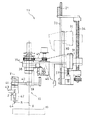
図1は、保護テープ貼付け装置の全体構成を示す斜視図である。この保護テープ貼付装置1は、基台2の手前に、オリエンテーションフラットを有する半導体ウエハW(以下、単に「ウエハW」という)が収納されたカセットC1が装填されるウエハ供給部3と、表面に保護テープTが貼付けられ切り抜かれた処理済みウエハW’を回収するウエハ回収部4とが配備されている。このウエハ供給部2とウエハ回収部3との間には、ロボットアーム5を備えたウエハ搬送機構6が配備されるとともに、基台2の右側奥にはアライメントステージ7が配備され、その上方にはウエハWに向けて保護テープTを供給するテープ供給部8が配備されている。また、テープ供給部8の右斜め下にはテープ供給部から供給されたセパレータ付きの保護テープTからセパレータSのみを回収するセパレータ回収部9が配備されている。アライメントステージ7の左横にはウエハWを載置して吸着保持するチャックテーブル10と、このチャックテーブル10に保持されたウエハWに保護テープTを貼付けるテープ貼付けユニット11と、ウエハWに貼付けて切断処理した後の不要テープT’を剥離するテープ剥離ユニット12とが配備されるとともに、その上方には、ウエハWに貼付けられた保護テープTをウエハWの外形に沿って切り抜き切断するテープ切断機構13が配備されている。また、基台2の左側上方には、テープ剥離ユニット12で剥離された不要テープT’を巻き取り回収するテープ回収部14が配備されている。さらに、チャックテーブル10を挟んで、ウエハWに貼付ける前の保護テープTと、回収前の不要テープT’から静電気を除去する静電気除去装置15がそれぞれに配備されている。
【0027】
以下、各機構について具体的に説明する。
【0028】
ウエハ供給部3は、昇降可能なカセット台17を備え、このカセット台17にパターン面を上向きにしたウエハWを多段に水平姿勢で差込み収納したカセットC1が載置されるようになっている。
【0029】
ウエハ搬送機構6に備えられたロボットアーム5は、水平に進退移動可能に構成されるとともに、全体が駆動旋回されるようになっている。ロボットアーム5の先端には、馬蹄形をした真空吸着式のウエハ保持部5aが備えられており、カセットC1に多段に収納されたウエハW同士の間隙にウエハ保持部5aを差し入れてウエハWを裏面から吸着保持し、吸着保持したウエハWをカセットC1から引き出して、後述するアライメントステージ7、チャックテーブル10、および、ウエハ回収部4の順に搬送するようになっている。
【0030】
アライメントステージ7は、ウエハ搬送機構6によって搬入載置されたウエハWを、その外周に形成されたオリエンテーションフラットOFに基づいて位置合わせを行うようになっている。
【0031】
チャックテーブル10は、ウエハ搬送機構6から移載されたウエハWを所定の位置合わせ姿勢で載置するとともに、図6に示すように、ウエハWの裏面全体を覆って吸着孔18を介して真空吸着するようになっている。また、このチャックテーブ10ルの上面には、後述するテープ切断機構13のカッタ刃44をウエハWの外形に沿って旋回移動させて保護テープを切断するためにカッタ走行溝19が形成されている。このカッタ走行溝19は、サイズの異なったウエハWの外形に応じたものが複数本設けられている。また、カッタ走行溝19のカッタ刃が最初に挿入される初期位置は、幅広の放射溝20となって、各カッタ走行溝19につながっている。
【0032】
図1に戻り、テープ供給部8は、装置本体の縦壁21に軸支されたテープボビン22から繰り出されたセパレータ付きの保護テープTをガイドローラ23群に巻回案内し、セパレータSを剥離した保護テープTをテープ貼付けユニット11に導くよう構成されている。また、テープボビン22に適度の回転抵抗を与えて過剰なテープ繰り出しが行われないように構成されている。なお、保護テープとしてはウヘハWの直径よりも幅広のものが使用される。
【0033】
セパレータ回収部9は、保護テープTから剥離されたセパレータSを巻き取る回収ボビン24が装置本体の縦壁21に軸支されて、縦壁背部の図示されない駆動機構によって巻き取り方向に回転駆動されるようになっている。
【0034】
テープ貼付けユニット11は、そのフレームがテープ走行方向にスライド可能になるように装置本体のレールに把持され、図示しないモータなどの駆動部を介して連動連結されている。また、フレームには、図7に示すように、貼付けローラ25が回転可能に軸支されているとともに、貼付けローラ25が図示しないシリンダなどによって上下陽動駆動するようになっている。つまり、貼付けローラ25が保護テープTの表面を押圧して転動しながらウエハWの表面に保護テープTを貼り付けてゆくようになっている。
【0035】
テープ剥離ユニット12は、そのフレームがテープ走行方向にスライド可能になるように装置本体のレールに把持され、図示しないモータなどの駆動部を介して連動連結されている。また、フレームには、図7に示すように、剥離ローラ26が回転可能に軸支されているとともに、剥離ローラ26が図示しないシリンダなどによって上下陽動駆動するようになっている。剥離ローラ26はウエハWの外形に沿って切断された後の不要な保護テープをウエハWから剥離するためのものである。
【0036】
テープ回収部14は、不要テープT’を巻き取る回収ボビン27が装置本体の縦壁21に軸支されて、縦壁背部の図示されない駆動機構によって巻き取り方向に回転駆動されるようになっている。
【0037】
図1に戻りウエハ回収部4は、昇降可能なカセット台28を備え、保護テープTが貼付けられ不要テープが切断除去された処理済みのウエハWを多段に水平姿勢で差込み収納したカセットC2がこのカセット台28に載置されるようになっている。
【0038】
テープ切断機構13は、図2に示すように、装置本体の縦壁21の背面には左右一対の縦レール30に沿ってスライド昇降可能に支持された可動台31が配備されている。この可動台31に連設した支持アーム31aが縦壁21の開口32を通して装置本体の前方に片持ち状に延出され、この支持アームにカッタユニット33が装備されている。
【0039】
可動台31は、ネジ軸34を正逆回転駆動することでねじ送り昇降されるようになっている。ネジ軸34は、図3に示すように、タイミングベルトなどを利用したスリップのない巻き掛け伝動機構35を介してモータ36に連動連結されている。また、可動台31の下降限度が、調節可能なストッパボルト37によって当接規制されるようになっている。なお、可動台31を昇降させるこれらの構成は、本発明の高さ調節手段に相当する。
【0040】
図2に戻り、支持アーム31aの先端近くには、チャックテーブル10の中心上に位置する縦軸心X周りに回転可能な切断駆動軸38が装備され、この切断駆動軸38の下端に連結されたボス部39に、一対の伸縮アーム40が水平スライド可能に支持されている。伸縮アーム40の先端に亘って連結された支持部材41に、門形に構成された回動ブラケット42が縦軸心Y周りに回転可能に軸支されている。
【0041】
この回動ブラケット42に水平支点Zを中心に揺動可能にカッタホルダ43が支持されるとともに、このカッタホルダ43の下部に、刃先を下向きにしたカッタ刃44が脱着可能に取り付けられている。
【0042】
ここで、切断駆動軸38は、タイミングベルトなどを利用したスリップのない巻き掛け伝動機構45を介してモータ46に連動連結されている。つまり、切断駆動軸38を回転駆動することで、カッタ刃44を半径Rで縦軸心X周りに旋回移動させて、ウエハWに貼付けた保護テープTを切り抜き切断するようになっている。
【0043】
また、回動ブラケット42は、図4に示すエアーシリンダ47によって縦軸心Y周りに回転操作可能となっており、この回動ブラケット42の回転位相調節によってカッタ刃44の刃縁の向きを調整することができるようになっている。
【0044】
また、カッタホルダ43も、図4に示すエアーシリンダ48によって支点Z周りに揺動操作可能となっており、カッタホルダ43と一体にカッタ刃44が上方の支点Z周りに揺動することで、カッタ刃44が縦軸心Xに対して遠近移動するようになっている。
【0045】
制御部47は、保護テープTに対するカッタ刃44の接触位置(高さ)を調節するために、モータ36の回転駆動を操作してテープ切断機構13の昇降駆動を制御している。なお、詳細な説明は、以下の動作説明で詳述する。
【0046】
次に、上記実施例装置を用いて保護テープTをウエハWの表面に貼付けるための一連の動作を説明する。
【0047】
ウエハWを多段に収納したカセットC1がウエハ供給部のカセット台17に載置されると、カセット台17が昇降移動し、取り出し対象のウエハWをロボットアーム5で取り出せる高さ位置で停止される。
【0048】
次に、ウエハ搬送機構6が旋回してロボットアーム5のウエハ保持部5aがカセットC1内のウエハ同士の隙間に挿入され、ロボットアーム5はそのウエハ保持部5aでウエハWを裏面(下面)から吸着保持して取り出し、ウエハWをアライメントステージ7に移載する。
【0049】
アライメントステージ7に載置されたウエハWは、オリエンテーションフラットOFを利用して位置合わせされ、位置合わせのすんだウエハWは再びロボットアーム5によって吸着保持されて搬出され、チャックテーブル10に移載される。
【0050】
チャックテーブル10に載置されたウエハWは、その中心がチャックテーブル10の中心上にあるように位置合わせされて吸着保持される。この時、図7に示すように、テープ貼付けユニット11とテープ剥離ユニット12は左側の初期位置に、また、テープ切断機構13のカッタユニット33は上方の初期位置でそれぞれ待機している。
【0051】
ウエハWの位置合わせがすむと、図8に示すように、テープ貼付けユニット11の貼付けローラ25が下降されるとともに、この貼付けローラ25で保護テープTを下方に押圧しながらウエハW上をテープ走行方向と逆方向(図8では左から右方向)に転動し、これによって保護テープTがウエハWの表面全体に均一に貼付けられる。そして、テープ貼付けユニット11が終端位置に達すると貼付けローラ25が上昇される。
【0052】
次に、モータ36が起動されてテープ切断機構13が下降され、図9に示すように、上方に待機していたカッタユニット33が切断作用位置まで下降され、カッタ刃44がチャックテーブル10の放射溝20の部位において保護テープTに突き刺さり貫通されて、予め設定された所定の高さ位置まで下降されたところで停止される。この場合、カッタ刃44の縦軸心Xに対する旋回半径Rが、処理対象となっているウエハWのサイズに対応するように、伸縮アーム40が予めスライド調節されている。
【0053】
カッタ刃44が所定の高さ位置で停止されると、モータ46が起動されて切断駆動軸が38が所定の方向に回転され、これに伴ってカッタ刃44が縦軸心X周りに旋回移動して、保護テープTがウエハ外形に沿って切断される。このとき、テープ貼付けユニット11とテープ剥離ユニット12によって、保護テープTには所定のテンションがかけられる。
【0054】
そして、このテープ切断行程では次のような制御が行われる。つまり、ウエハWのオリエンテーションフラット領域でのテープ切断行程においては、カッタ刃44がカッタホルダ43と一体に支点Zを中心にして揺動させることでオリエンテーションフラットOFに追従する。オリエンテーションフラットOFの始端から中央部位までの前半では、カッタ刃44はその旋回移動に伴って次第にウエハW中心側に接近揺動し、中央部位からオリエンテーションフラットOFの終端までの後半では、カッタ刃44はその旋回移動に伴ってウエハW中心側から元の旋回半径Rまで次第に離反揺動することになり、このカッタ刃44の支点Z周りの揺動に連動してカッタユニット33がモータ36によって昇降制御される。
【0055】
つまり、カッタ刃44が旋回半径Rの位置からウエハW中心側に接近揺動するオリエンテーションフラット領域の前半では、その揺動量に応じてカッタユニット33を下降制御するとともに、オリエンテーションフラット領域の後半では、その揺動量に応じてカッタユニット33を元の高さ位置に向けて上昇制御する。つまり、図11に示すように、オリエンテーションフラット領域におけるカッタ刃44の保護テープTに対する接触位置e’を、ウエハW外形の円弧領域におけるカッタ刃44の保護テープTに対する接触位置eと同一に維持することができるのである。
【0056】
なお、カッタユニット33を昇降制御するモータ36の作動を司る制御部47には、ウエハWおよびオリエンテーションフラットOFのサイズ、ウエハW表面から支点Zまでの高さ、などのデータが予め入力されるとともに、接触位置eを一定に維持するために必要とされるカッタユニット33の目標高さ位置が、カッタ刃44の縦軸心X周りでの旋回位置に対応したマップデータとして記憶格納されている。したがって、カッタ刃44の旋回位置がロータリエンコーダなどのセンサで検出されると、その検出データに基づいてカッタユニット33の目標高さ位置が割り出され、これによってモータ36が回転制御されるようになっている。
【0057】
ウエハW外周に沿ったテープ切断が終了すると、切断駆動軸38が停止されるとともに、図10に示すように、カッタユニット33は元の待機位置まで上昇される。次に、テープ剥離ユニット12がウエハWウエをテープ走行方向と逆方向へ移動しながらウエハW上で切り抜き切断されて残った不要テープT’を巻き上げ剥離する。
【0058】
テープ剥離ユニット12が剥離作業の終了位置に達すると、テープ剥離ユニット12とテープ貼付けユニット11とがテープ走行方向に移動して初期位置に復帰する。このとき、不要テープT’が回収ボビン27に巻き取られるとともに、一定量の保護テープTがテープ供給部8から繰り出される。
【0059】
以上で保護テープTをウエハWの表面に貼付ける一連の動作が終了し、以後、この動作が繰り返される。この場合、所定枚数の処理が終了するごとに、自動的あるいは人為操作によって出される指令によって、カッタユニット22の切断作用高さを所定量づつ変更し、図5に示すように、カッタ刃44の保護テープTに対する接触位置e、つまり、テープ切断位置を所定ピッチpづつ上方にずらしてゆくことで、1枚のカッタ刃44を交換することなく多数枚の切断処理に使用することができる。
【0060】
本実施例では、オリエンテーションフラットを有するウエハWに貼り付けた保護テープTを切断する過程で、保護テープTに対するカッタ刃44の接触位置を同一にするようにテープ切断機構44を操作してカッタ刃44の高さを制御することにより、略同一条件でもって保護テープを切断することができ、かつ、保護テープTのカット品質を均一に保つことができる。
【0061】
また、所定枚数の保護テープTを切断するごとに、保護テープTに対するカッタ刃44の接触位置を所定ピッチだけ移動変更することにより、1枚のカッタ刃44を長時間にわたって使用することができる。したがって、カッタ刃44の取替え頻度を低減させることがき、作業性の向上を図ることもできる。
【0062】
本発明は、以下のような形態で実施することもできる。
【0063】
(1)上記実施形態では、カッタユニット33の昇降駆動手段を制御して、オリエンテーションフラット領域でのカッタ刃44の高さを制御する場合を示したが、カッタユニット33にカッタ刃44を独立して駆動昇降する手段を備え、カッタユニット33を所定の切断作用高さに固定したままでオリエンテーションフラット領域でのカッタ刃44の高さ制御を行うこともできる。これによると、昇降制御される作動部が軽量となり、精度および応答性に優れた制御を実行することができる。
【0064】
(2)上記実施形態では、カッタ刃44をウエハWに対して昇降させているが、カッタ刃の支点Z周りの揺動に連動してチャックテーブル10を昇降制御することで、保護テープTに対するカッタ刃44の接触位置を一定に維持することも可能である。
【0065】
(3)カッタ刃44を水平に遠近移動可能に構成して、オリエンテーションフラット領域でカッタ刃44を一定姿勢のまま平行に水平移動させてオリエンテーションフラットOFに追従させるようにすれば、カッタ刃44を昇降制御することなく保護テープTに対するカッタ刃44の接触位置を一定に維持してウエハW全周のテープ切断を行うことができる。
【0066】
【発明の効果】
以上の説明から明らかなように、この発明によれば、保護テープに対するカッタ刃の接触位置を一定に維持してテープ切断を行うことで、オリエンテーションフラットを有するウエハに貼付けられた保護テープを、ウエハ全周において良好かつ均一なカット品質を確保することができる。
【図面の簡単な説明】
【図1】保護テープ貼付け装置の全体構成を示す斜視図である。
【図2】テープ切断機構の側面図である。
【図3】テープ切断機構の背面図である。
【図4】カッタユニットの要部を示す正面図である。
【図5】カッタ刃の正面図である。
【図6】テープ切断機構の要部とチャックテーブルを示す斜視図である。
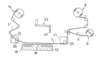
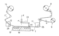
【図7】保護テープ貼付け行程の概略正面図である。
【図8】保護テープ貼付け行程の概略正面図である。
【図9】保護テープ切断行程の概略正面図である。
【図10】保護テープ剥離行程の概略正面図である。
【図11】本発明における保護テープ切断部位を示す縦断面図である。
【図12】半導体ウエハの平面図である。
【図13】従来の保護テープ切断部位を示す縦断面図である。
【符号の説明】
44 … カッタ刃
W … 半導体ウエハ
T … 保護テープ
Z … 支点
OF … オリエンテーションフラット
e,e’… 接触位置[0001]
TECHNICAL FIELD OF THE INVENTION
The present invention provides a protective tape cutting method for cutting a protective tape by attaching a wide protective tape to a surface of a semiconductor wafer (hereinafter, simply referred to as a “wafer”), and then moving the cutter blade along the outer shape of the wafer to cut the protective tape. It relates to an apparatus used for this.
[0002]
[Prior art]
One of the processing steps of a wafer is a thin processing step. As a processing means used in this step, mechanical or chemical means such as grinding, polishing, or etching is appropriately selected and used. In these thin processing means, in order to prevent the pattern formed on the wafer surface from being damaged or stained, a protective tape is attached to the surface of the wafer to protect it, and then the mechanical or chemical thin processing is performed on the back surface of the wafer. In general, a protective tape wider than the diameter of the wafer is attached to the surface of the wafer, and then the cutter blade is moved along the outer shape of the wafer to cut out and cut the protective tape.
[0003]
[Problems to be solved by the invention]
The mechanical rigidity and strength of a wafer are reduced by being subjected to thin processing. Therefore, there is a tendency that a hard and thick protective tape having appropriate rigidity is attached to the surface of the wafer in order to suppress the addition of strength and warpage to the wafer.
[0004]
However, when the protective tape is hard and thick, it is difficult to cut the protective tape with a cutter blade, and if the cut surface of the protective tape is not cut sharply, stress may be applied during wafer processing such as backside polishing and the wafer may be damaged. There is.
[0005]
Further, since the degree of wear of the cutter blade is increased, the life of the cutter blade is shortened, the frequency of replacement thereof is increased, and the workability is reduced.
[0006]
Further, the cutter blade used in the cutting step of the protective tape is supported swingably about an upper fulcrum so as to be able to move toward and away from the wafer W so as to appropriately follow the outer periphery of the wafer. Specifically, as shown in FIG. 12, in the wafer W having the orientation flat OF, when the
[0007]
However, when the
[0008]
For example, as shown in FIG. 13, a
[0009]
When the tape cutting position of the
[0010]
Further, as the number of cuts increases, the tape cut quality in the orientation flat area further decreases, so that the number of wafers that can be cut until the tape cut quality reaches an allowable limit is reduced, and the cutter blade is cut. The frequency of replacement must be high.
[0011]
The present invention has been made in view of such circumstances, and a main object of the present invention is to provide a protective tape cutting method and an apparatus for efficiently cutting a protective tape along the outer shape of a semiconductor wafer. Is what you do.
[0012]
[Means for Solving the Problems]
The present invention has the following configuration to achieve the above object.
[0013]
The invention according to claim 1 is a protective tape cutting method in which after a wide protective tape is attached to a surface of a semiconductor wafer having an orientation flat, a cutter blade is swiveled along the outer shape of the semiconductor wafer to cut the protective tape. So,
In the process of cutting the protective tape, the cutter blade is swiveled along the outer shape of the semiconductor wafer while maintaining a constant contact position of the cutter blade with the protective tape.
[0014]
(Operation / Effect) Since the protective tape is cut along the outer shape of the semiconductor wafer while keeping the contact position of the cutter blade with the protective tape constant, even in a semiconductor wafer having an orientation flat, the cutter blade can be cut all around. Can be cut while contacting the same position with the protective tape. Therefore, the cutting conditions of the orientation flat region are the same as those of the other arc portions, so that the protective tape can be cut well and the cut quality can be kept uniform.
[0015]
According to a second aspect of the present invention, in the protective tape cutting method according to the first aspect, in the cutting step in the orientation flat region, the cutter blade is swung to follow the orientation flat, and the cutting blade and the semiconductor wafer are separated from each other. The relative height is controlled with the turning movement of the cutter blade, and the cutter blade is turned along the outer shape of the semiconductor wafer while the contact position of the cutter blade with respect to the protective tape is kept constant.
[0016]
(Function / Effect) When the cutter blade swings and follows the orientation flat in the orientation flat area, the cutter blade is interlocked with the turning drive of the cutter blade so as to absorb a change in the contact position of the cutter blade with the protective tape. By changing and controlling the relative height between the swing fulcrum and the semiconductor wafer, the protective tape can be cut at the same position of the cutter blade. That is, the protective tape cutting method according to the first aspect can be suitably performed.
[0017]
According to a third aspect of the present invention, there is provided a protective tape cutting device for cutting a protective tape by pasting a wide protective tape on a surface of a semiconductor wafer having an orientation flat, and then rotating the cutter blade along the outer shape of the semiconductor wafer to cut the protective tape. So,
A height adjusting unit configured to swing the cutter blade driven to rotate around the fulcrum to follow the outer periphery of the semiconductor wafer, and to change and adjust the height of the fulcrum with respect to the semiconductor wafer;
Control means for operating the height adjusting means in conjunction with the turning movement of the cutter blade in the orientation flat area to maintain a constant contact position of the cutter blade with the protective tape;
It is characterized by having.
[0018]
(Operation / Effect) As the cutter blade swings and follows the orientation flat, the inclination posture of the cutter blade changes, and the contact position of the cutter blade with the protective tape changes in the blade edge direction. By controlling the height adjusting means in conjunction with the turning movement of the cutter blade so as to absorb the change in the contact position, the protective tape can be cut at the same position of the cutter blade. Therefore, the protective tape cutting method described in claim 1 can be suitably realized.
[0019]
The invention according to claim 4 is the protective tape cutting device according to
Each time a predetermined number of protection tapes are cut, the contact position of the cutter blade with respect to the protection tape is changed and moved by a predetermined pitch.
[0020]
(Operation / Effect) Every time a predetermined number of tape cutting processes with a fixed contact position with respect to the protective tape are performed, the operation height of the cutter blade is shifted by a predetermined pitch. Accordingly, a plurality of new positions of the cutter blade can be used in one cutter blade, and the service life of the cutter blade can be extended, and the frequency of replacing the cutter blade can be reduced, thereby improving workability. Can be.
[0021]
The present invention also discloses the following solution.
[0022]
(1) In a protective tape attaching device for attaching a protective tape to a surface of a semiconductor wafer having an orientation flat,
Holding means for mounting and holding the semiconductor wafer,
Tape supply means for supplying a protective tape toward the held semiconductor wafer,
Sticking means for sticking the supplied protective tape to the surface of the semiconductor wafer,
Tape cutting means for turning the cutter blade along the outer shape of the semiconductor wafer to cut the protection tape attached to the surface of the semiconductor wafer,
Peeling means for peeling off unnecessary tape after cutting the protective tape by the tape cutting mechanism,
A collecting unit for collecting the peeled unnecessary tape,
And the tape cutting means is configured to swing the cutter blade driven to rotate around the fulcrum to follow the outer periphery of the wafer, and height adjusting means for changing and adjusting the height of the fulcrum with respect to the semiconductor wafer. ,
Control means for operating the height adjusting means in conjunction with the turning movement of the cutter blade in the orientation flat area to maintain a constant contact position of the cutter blade with the protective tape. Tape sticking device.
[0023]
According to the invention of the above (1), the protection tape is supplied from the tape supply means toward the semiconductor wafer placed on the holding means, and the protection tape is attached to the surface of the semiconductor wafer by the attaching means. Next, the tape cutting means operates to cut the protective tape along the outer shape of the semiconductor wafer. In the process of cutting the protective tape, the cutter blade swings and follows the orientation flat, so that the inclination posture of the cutter blade changes, and the contact position of the cutter blade with the protective tape changes in the blade edge direction. The height adjusting means is controlled in conjunction with the turning movement of the cutter blade so as to absorb the change in the contact position, and cuts the protective tape at the same position of the cutter blade. Unnecessary protection tape cut out in a substantially shape of the semiconductor wafer is collected.
[0024]
Therefore, the protective tape adhered to the wafer having the orientation flat can be satisfactorily cut under the same cutting conditions over the entire circumference of the wafer, and uniform cutting quality can be ensured.
[0025]
BEST MODE FOR CARRYING OUT THE INVENTION
An embodiment of the present invention will be described below with reference to the drawings.
First, the present embodiment will be described with reference to the drawings, taking a protective tape attaching device provided with a protective tape cutting device as an example.
[0026]
FIG. 1 is a perspective view showing the overall configuration of the protective tape attaching device. The protective tape applying apparatus 1 includes a
[0027]
Hereinafter, each mechanism will be specifically described.
[0028]
The
[0029]
The
[0030]
The
[0031]
The chuck table 10 mounts the wafer W transferred from the
[0032]
Returning to FIG. 1, the tape supply unit 8 guides the protective tape T with a separator fed from a
[0033]
In the
[0034]
The
[0035]
The
[0036]
In the
[0037]
Returning to FIG. 1, the wafer collecting section 4 is provided with a cassette table 28 which can be moved up and down. It is designed to be placed on a cassette table 28.
[0038]
As shown in FIG. 2, the
[0039]
The
[0040]
Returning to FIG. 2, a cutting
[0041]
A
[0042]
Here, the cutting
[0043]
The
[0044]
Also, the
[0045]
The
[0046]
Next, a series of operations for attaching the protective tape T to the surface of the wafer W using the above-described apparatus will be described.
[0047]
When the cassette C1 in which the wafers W are stored in multiple stages is placed on the cassette table 17 of the wafer supply unit, the cassette table 17 moves up and down and stops at a position where the robot W can take out the wafer W to be taken out. .
[0048]
Next, the
[0049]
The wafer W placed on the
[0050]
The wafer W placed on the chuck table 10 is aligned and held by suction so that the center thereof is on the center of the chuck table 10. At this time, as shown in FIG. 7, the
[0051]
When the alignment of the wafer W is completed, the
[0052]
Next, the
[0053]
When the
[0054]
The following control is performed in the tape cutting process. That is, in the tape cutting process in the orientation flat area of the wafer W, the
[0055]
That is, in the first half of the orientation flat area where the
[0056]
In addition, data such as the size of the wafer W and the orientation flat OF, the height from the surface of the wafer W to the fulcrum Z, and the like are input in advance to the
[0057]
When the tape cutting along the outer periphery of the wafer W is completed, the cutting
[0058]
When the
[0059]
Thus, a series of operations for attaching the protective tape T to the surface of the wafer W is completed, and thereafter, this operation is repeated. In this case, every time the processing of a predetermined number of sheets is completed, the cutting action height of the
[0060]
In the present embodiment, in the process of cutting the protection tape T attached to the wafer W having the orientation flat, the
[0061]
Further, each time a predetermined number of protective tapes T are cut, the contact position of the
[0062]
The present invention can be implemented in the following forms.
[0063]
(1) In the above-described embodiment, the case where the height of the
[0064]
(2) In the above embodiment, the
[0065]
(3) If the
[0066]
【The invention's effect】
As is apparent from the above description, according to the present invention, the tape is cut while maintaining the contact position of the cutter blade with the protective tape constant, so that the protective tape attached to the wafer having the orientation flat can be removed from the wafer. Good and uniform cutting quality can be secured over the entire circumference.
[Brief description of the drawings]
FIG. 1 is a perspective view showing an overall configuration of a protective tape attaching device.
FIG. 2 is a side view of the tape cutting mechanism.
FIG. 3 is a rear view of the tape cutting mechanism.
FIG. 4 is a front view showing a main part of the cutter unit.
FIG. 5 is a front view of the cutter blade.
FIG. 6 is a perspective view showing a main part of a tape cutting mechanism and a chuck table.
FIG. 7 is a schematic front view of a protective tape attaching process.
FIG. 8 is a schematic front view of a protective tape attaching process.
FIG. 9 is a schematic front view of a protection tape cutting step.
FIG. 10 is a schematic front view of a protective tape peeling process.
FIG. 11 is a longitudinal sectional view showing a protection tape cutting portion in the present invention.
FIG. 12 is a plan view of a semiconductor wafer.
FIG. 13 is a longitudinal sectional view showing a conventional protection tape cutting portion.
[Explanation of symbols]
44… cutter blade
W… Semiconductor wafer
T: Protective tape
Z ... fulcrum
OF… Orientation flat
e, e '... contact position
Claims (4)
前記保護テープを切断する過程で保護テープに対するカッタ刃の接触位置を一定に維持させながら、半導体ウエハの外形に沿ってカッタ刃を旋回移動させることを特徴とする保護テープカット方法。After attaching a wide protective tape to the surface of the semiconductor wafer having an orientation flat, a protective tape cutting method for cutting the protective tape by rotating the cutter blade along the outer shape of the semiconductor wafer,
A method for cutting a protective tape, comprising: rotating a cutter blade along an outer shape of a semiconductor wafer while maintaining a constant contact position of the cutter blade with the protective tape in a process of cutting the protective tape.
オリエンテーションフラット領域での切断行程では、カッタ刃を揺動させてオリエンテーションフラットに追従させるとともに、カッタ刃と半導体ウエハとの相対高さをカッタ刃の旋回移動に伴って制御し、保護テープに対するカッタ刃の接触位置を一定に維持させながら、半導体ウエハの外形に沿ってカッタ刃を旋回移動させることを特徴とする保護テープカット方法。The protective tape cutting method according to claim 1,
In the cutting process in the orientation flat area, the cutter blade is swung to follow the orientation flat, and the relative height between the cutter blade and the semiconductor wafer is controlled with the turning movement of the cutter blade, so that the cutter blade with respect to the protective tape is controlled. Wherein the cutter blade is swiveled along the outer shape of the semiconductor wafer while keeping the contact position of the protective tape constant.
旋回駆動されるカッタ刃を支点周りに揺動させて半導体ウエハ外周に追従するように構成するとともに、前記支点の半導体ウエハに対する高さを変更調節する高さ調節手段と、
オリエンテーションフラット領域でのカッタ刃の旋回移動に連動して前記高さ調節手段を作動させて、保護テープに対するカッタ刃の接触位置を一定に維持する制御手段と
を備えていることを特徴とする保護テープカット装置。After pasting a wide protective tape on the surface of a semiconductor wafer having an orientation flat, a protective tape cutting device that cuts the protective tape by rotating the cutter blade along the outer shape of the semiconductor wafer,
A height adjusting unit configured to swing the cutter blade driven to rotate around the fulcrum to follow the outer periphery of the semiconductor wafer, and to change and adjust the height of the fulcrum with respect to the semiconductor wafer;
Control means for operating the height adjusting means in conjunction with the turning movement of the cutter blade in the orientation flat area to maintain a constant contact position of the cutter blade with the protective tape. Tape cutting device.
所定枚数の保護テープを切断するごとに、保護テープに対するカッタ刃の接触位置を所定ピッチづつ変更移動するように構成したことを特徴とする保護テープカット装置。The protective tape cutting device according to claim 3,
A protective tape cutting device, wherein a contact position of a cutter blade with respect to a protective tape is changed and moved by a predetermined pitch every time a predetermined number of protective tapes are cut.
Priority Applications (1)
| Application Number | Priority Date | Filing Date | Title |
|---|---|---|---|
| JP2002285731A JP4067373B2 (en) | 2002-09-30 | 2002-09-30 | Protective tape cutting method and apparatus |
Applications Claiming Priority (1)
| Application Number | Priority Date | Filing Date | Title |
|---|---|---|---|
| JP2002285731A JP4067373B2 (en) | 2002-09-30 | 2002-09-30 | Protective tape cutting method and apparatus |
Publications (2)
| Publication Number | Publication Date |
|---|---|
| JP2004122242A true JP2004122242A (en) | 2004-04-22 |
| JP4067373B2 JP4067373B2 (en) | 2008-03-26 |
Family
ID=32278952
Family Applications (1)
| Application Number | Title | Priority Date | Filing Date |
|---|---|---|---|
| JP2002285731A Expired - Fee Related JP4067373B2 (en) | 2002-09-30 | 2002-09-30 | Protective tape cutting method and apparatus |
Country Status (1)
| Country | Link |
|---|---|
| JP (1) | JP4067373B2 (en) |
Cited By (5)
| Publication number | Priority date | Publication date | Assignee | Title |
|---|---|---|---|---|
| JP2006095606A (en) * | 2004-09-28 | 2006-04-13 | Nitto Denko Corp | Protective tape cutting method, and device implementing the same |
| WO2007083455A1 (en) * | 2006-01-18 | 2007-07-26 | Lintec Corporation | Sheet cutting apparatus and sheet cutting method |
| KR101145517B1 (en) * | 2004-08-19 | 2012-05-16 | 닛토덴코 가부시키가이샤 | Method and apparatus for joining protective tape |
| JP2013099811A (en) * | 2011-11-08 | 2013-05-23 | Shima Seiki Mfg Ltd | Cutting machine |
| KR101900137B1 (en) | 2012-12-13 | 2018-09-20 | 주식회사 쿠온솔루션 | Tape cutting device |
-
2002
- 2002-09-30 JP JP2002285731A patent/JP4067373B2/en not_active Expired - Fee Related
Cited By (6)
| Publication number | Priority date | Publication date | Assignee | Title |
|---|---|---|---|---|
| KR101145517B1 (en) * | 2004-08-19 | 2012-05-16 | 닛토덴코 가부시키가이샤 | Method and apparatus for joining protective tape |
| JP2006095606A (en) * | 2004-09-28 | 2006-04-13 | Nitto Denko Corp | Protective tape cutting method, and device implementing the same |
| JP4498085B2 (en) * | 2004-09-28 | 2010-07-07 | 日東電工株式会社 | Protective tape cutting method and apparatus using the same |
| WO2007083455A1 (en) * | 2006-01-18 | 2007-07-26 | Lintec Corporation | Sheet cutting apparatus and sheet cutting method |
| JP2013099811A (en) * | 2011-11-08 | 2013-05-23 | Shima Seiki Mfg Ltd | Cutting machine |
| KR101900137B1 (en) | 2012-12-13 | 2018-09-20 | 주식회사 쿠온솔루션 | Tape cutting device |
Also Published As
| Publication number | Publication date |
|---|---|
| JP4067373B2 (en) | 2008-03-26 |
Similar Documents
| Publication | Publication Date | Title |
|---|---|---|
| JP4136890B2 (en) | Method and apparatus for cutting protective tape | |
| JP3983053B2 (en) | Protective tape cutting method and protective tape applying apparatus using the same | |
| KR101145517B1 (en) | Method and apparatus for joining protective tape | |
| JP2007227553A (en) | Sticking method of pressure-sensitive adhesive tape to semiconductor wafer, and apparatus using same | |
| KR101498744B1 (en) | Protective tape joining apparatus | |
| JP2008066523A (en) | Adhesive tape cutting method, and adhesive tape sticking apparatus employing the same | |
| TWI330582B (en) | Method and apparatus for cutting protective tape of semiconductor wafer | |
| WO2007018041A1 (en) | Sheet application device and application method | |
| JP6087515B2 (en) | Semiconductor wafer protective tape cutting method and protective tape cutting device | |
| TWI353647B (en) | Method of cutting a protective tape and protective | |
| JP4067373B2 (en) | Protective tape cutting method and apparatus | |
| JP4079679B2 (en) | Unnecessary semiconductor wafer removal method and apparatus | |
| JP4326363B2 (en) | Adhesive sheet pasting method and apparatus using the same | |
| JP2005019841A (en) | Method and device for adhering ultraviolet curing type self-adhesive tape and article formed by using the same | |
| JP2005125459A (en) | Method of cutting protective tape for semiconductor wafer, and device for cutting the protective tape | |
| JP7240440B2 (en) | Adhesive tape applying method and adhesive tape applying apparatus | |
| JPH061771B2 (en) | Wafer protection film cutting method | |
| KR20180111608A (en) | Apparatus for cutting adhesive tape | |
| JP2005123595A (en) | Method and device for sticking adhesive tape | |
| JP4350018B2 (en) | Adhesive tape sticking device | |
| JP4393334B2 (en) | Adhesive tape cutting device | |
| JP2013230532A (en) | Protective tape cutting method and protective tape cutting apparatus of semiconductor wafer | |
| JP4632632B2 (en) | Adhesive tape application method and apparatus | |
| JP2005014184A (en) | Method of cutting ultraviolet-ray-setting adhesive tape and article formed by using the same |
Legal Events
| Date | Code | Title | Description |
|---|---|---|---|
| A621 | Written request for application examination |
Free format text: JAPANESE INTERMEDIATE CODE: A621 Effective date: 20041108 |
|
| A977 | Report on retrieval |
Free format text: JAPANESE INTERMEDIATE CODE: A971007 Effective date: 20070731 |
|
| A131 | Notification of reasons for refusal |
Free format text: JAPANESE INTERMEDIATE CODE: A131 Effective date: 20071023 |
|
| A521 | Written amendment |
Free format text: JAPANESE INTERMEDIATE CODE: A523 Effective date: 20071207 |
|
| TRDD | Decision of grant or rejection written | ||
| A01 | Written decision to grant a patent or to grant a registration (utility model) |
Free format text: JAPANESE INTERMEDIATE CODE: A01 Effective date: 20080108 |
|
| A61 | First payment of annual fees (during grant procedure) |
Free format text: JAPANESE INTERMEDIATE CODE: A61 Effective date: 20080108 |
|
| FPAY | Renewal fee payment (prs date is renewal date of database) |
Free format text: PAYMENT UNTIL: 20110118 Year of fee payment: 3 |
|
| R150 | Certificate of patent (=grant) or registration of utility model |
Free format text: JAPANESE INTERMEDIATE CODE: R150 |
|
| FPAY | Renewal fee payment (prs date is renewal date of database) |
Free format text: PAYMENT UNTIL: 20140118 Year of fee payment: 6 |
|
| R250 | Receipt of annual fees |
Free format text: JAPANESE INTERMEDIATE CODE: R250 |
|
| LAPS | Cancellation because of no payment of annual fees |