【0001】
【発明の属する技術分野】
本発明は、コンバインに関するもので、農業機械の技術分野に属する。
【0002】
【従来の技術】
従来の技術は、コンバインの左右旋回と刈取装置の昇降を行う操向操作具において、この操向操作具本体の上部にコンバインの各部分の操作を実行する各種スイッチを設ける構成であった(例えば、特許文献1参照。)。
【0003】
【特許文献1】
特開平8−211956号公報
【0004】
【発明が解決しようとする課題】
前述のような構成では、操向操作具の本体にスイッチを設ける構成であるので、スイッチの数が限定されていた。このため、使用頻度の多いスイッチであっても操向操作具の本体にスイッチを設けることができず、このため、作業者側方のパネル部分にスイッチ類を設けており、スイッチの操作が容易にできないという欠点があった。
【0005】
【課題を解決するための手段】
本発明は、上述した課題を解決するために、次の如き技術手段を講ずるものである。すなわち、請求項1記載の発明では、走行装置1を有する車台2の上方には脱穀装置3を有し、該脱穀装置3の前方には、多条列の植立穀稈を引き起こす複数の引起装置4と、該引起装置4で引き起こした穀稈を刈り取って後方の脱穀装置3へ向けて搬送する刈取装置5を設け、前記脱穀装置3の右側にはこの脱穀装置3で脱穀選別した穀粒を一時貯溜するグレンタンク6を設け、該グレンタンク6の前方には操作部7を設けたコンバインにおいて、該操作部7には操向操作具8を設け、該操向操作具8を左右方向へ傾動させるとコンバインが左右旋回し、操向操作具8を前後方向へ傾動させると刈取装置5が昇降する構成とし、前記操向操作具8と一体的に移動する操作パネル9を設けたことを特徴とするコンバインとしたものである。
【0006】
上記構成によると、操作部7に設けている操向操作具8を左方向に傾動させるとコンバインは左旋回し、右方向に傾動させるとコンバインは右旋回する。また、操向操作具8を前方へ傾動させると刈取装置5は下降し、後方へ傾動させると刈取装置5は上昇する。このように操向操作具8を前後左右に傾動させると、操作パネル9も操向操作具8とに一体的に前後左右に移動する。
【0007】
請求項2記載の発明では、前記操向操作具8の後方には該操向操作具8と一体的に移動して作業者の手首を支持する支持手段10を設けたことを特徴とする請求項1記載のコンバインとしたものである。
上記構成によると、請求項1の作用とともに、作業者が操向操作具8を操作するときにおいて、操向操作具8を手で把持して手首部分を支持手段10上に載置した状態で操向操作具8を前後左右に操作する。手首を支持している支持手段10も手首とともに一体的に前後左右方向へ移動する。
【0008】
請求項3記載の発明では、前記操作パネル9及び支持手段10は、操向操作具8に対して位置変更可能に構成したことを特徴とする請求項2記載のコンバインとしたものである。
上記構成によると、請求項2の作用とともに、操作パネル9と支持手段10とは、作業状況に応じて操向操作具8に対して位置変更する。
【0009】
【発明の効果】
本発明は、前述のごとく構成したので、請求項1記載の発明では、操向操作具8を前後左右方向へ操作しながら操作パネル9を操作できるので、操作性が向上する。また、コンバインを運転中は作業者の視界は前方にあるが、この前方視界から目をそらすことなく操作パネル9を操作するので安全な作業が可能となる。
【0010】
請求項2記載の発明においては、請求項1の効果とともに、操向操作具8を操作するときには、作業者の手首部分を支持手段10上に載置するので、疲れが少なくなり作業環境が向上する。特に、長時間操向操作具8を操作し続けても疲れが少なくなり作業能率の低下を防止できる。
【0011】
請求項3記載の発明においては、請求項2の効果とともに、操作パネル9と支持手段10は、作業状態や作業者の好みにより操向操作具8に対して位置変更可能なので、作業に適した状態で操向操作具8を操作でき、操作性が向上するようになる。
【0012】
【発明の実施の形態】
図1及び図2には、本発明の実施の形態を具現化したコンバインが示されている。
走行装置1を有する車台2の前方には、刈取装置5が設けられている。この刈取装置5には、植立穀稈を分草する分草具11と、植立穀稈を引き起こす引起装置4と、植立穀稈を刈り取る刈刃13と、該刈刃13にて刈り取られた穀稈を挟持して後方に搬送する株元搬送装置14が設けられている。この株元搬送装置14の後方には、この株元搬送装置14から搬送されてくる穀稈を引き継いで搬送する供給搬送装置15が設けられている。
【0013】
前記刈取装置5は、走行伝動装置16の上方の支点を中心にして上下動する刈取装置支持フレーム17にて、その略左右中間部で支持されていて、刈取装置5は刈取装置支持フレーム17と共に上下動する構成である。
車台2の上方には、前記供給搬送装置15から搬送されてくる穀稈を引き継いで搬送するフィードチェン18を有する脱穀装置3と、該脱穀装置3の右側方であって、この脱穀装置3で脱穀選別された穀粒を一時貯溜するグレンタンク6と、該グレンタンク6の前方に位置していてコンバインの各種操作を実行する操作部7が載置されている。
【0014】
脱穀装置3の後方には、前記フィードチェン18から搬送されてくる排稈を引き継いで搬送する排稈チェン12と、該排稈チェン12の終端部下方には排稈を切断するカッター装置19が設けられている。また、この実施例のカッター装置19の後方には、排稈を結束するノッター等の他の作業機を装着してもよい。
【0015】
前記グレンタンク6内の穀粒量が満杯となると、揚穀筒20と穀粒排出オーガ21から穀粒を機外へと排出する。揚穀筒20は電気モータ(図示せず)にて旋回可能に構成され、また、穀粒排出オーガ21油圧シリンダ22にて昇降可能に構成されている。そして、穀粒排出オーガ21は揚穀筒20の上部に連結されていて一体構成なので、揚穀筒20が旋回すると、穀粒排出オーガ21も一緒に旋回する構成となっている。
【0016】
このようなコンバインを前進させて刈取作業を実行すると、圃場面に植立している穀稈は、分草具11にて分草され、その後、引起装置4にて引き起こされて刈刃13にて刈り取られる。その後、株元搬送装置14にて後方へ搬送され、供給搬送装置15へ引き継ぎ搬送される。この供給搬送装置15に引き継がれた穀稈は、さらに後方へと搬送されていく。そして、脱穀装置16のフィードチェン18へと引継ぎ搬送されて、穀稈はフィードチェン18で後方へ搬送されながら脱穀装置3にて脱穀選別される。
【0017】
このように脱穀選別された穀粒は、一番揚穀筒23からグレンタンク6内へと搬送されて一時貯留される。該グレンタンク6内に貯留される穀粒量が満杯になると、操作部7の報知手段(ブザーや表示装置)でオペレータに報知される。するとオペレータは刈取作業を中断して、グレンタンク6内の穀粒を機外へと排出する作業を開始する。コンバインを任意の位置(トラック近傍位置)へと移動させ、穀粒排出オーガ21をオーガ受け24から離脱させて穀粒排出口21aをトラックの荷台等の位置へ移動させる。そして、操作部7に設けている穀粒排出レバー25を入り状態として、グレンタンク6内の穀粒を機外へと排出する。グレンタンク6内の穀粒排出が終了すると、穀粒排出オーガ21は再びオーガ受け24へと収納されていく。
【0018】
前記走行伝動装置16の詳細構成について、図3により説明する。エンジン26の出力軸26aにはプーリ26b,プーリ26c及びプーリ26dが取り付けられている構成である。プーリ26bが回転駆動するとともに、クラッチが入り状態になるとグレンタンク6内の下部ラセン(図示せず)が駆動して、穀粒排出オーガ21の穀粒排出口21aから穀粒が機外へと排出される構成である。前記プーリ26dが回転駆動するとともに、脱穀クラッチ(図示せず)が入り状態になると、脱穀装置3が駆動する構成である。前記プーリ26cは走行伝動装置16を駆動するプーリである。
【0019】
プーリ26cからベルト28,プーリ29を介して油圧無段変速装置27の可変油圧ポンプ27aの入力軸30に動力が伝達される構成である。この可変油圧ポンプ27aの斜板の傾斜角度を変更することにより、定量油圧モータ27bへの送油量と送油方向が変わり、出力軸31の回転数と回転方向が変わる構成である。32は、入力軸30に固定のファンであり、このファン33によって起風された風は油圧無段変速装置27方向へ送風されていき、油圧無段変速装置27を冷却する構成である。
【0020】
前記出力軸31の動力は、迂回伝動ケース33内の歯車34,歯車35,歯車36及び歯車37を介して減速伝動されていき、走行伝動装置16の入力軸38に動力伝達されていく。この入力軸38には歯車40と歯車41を有する移動体39が設けられていて、この移動体39は軸38の長手方向に移動する。歯車41には爪部49bがあり、歯車42にも爪部49aが構成されている。また、入力軸38には長手方向に移動しない歯車38が遊嵌して設けられている。43は刈取装置5へ動力伝達するプーリであり、入力軸38に対して固着して設けられている。
【0021】
前記入力軸38の下手側には軸44が設けられていて、この軸44には、歯車45,歯車46,歯車47及び歯車48が固着して設けられている。前記移動体39が移動して歯車41の爪部49bと歯車42の爪部49aが噛み合うと、入力軸38の動力は歯車42と歯車45で低速変速されて軸44に伝達される構成である。移動体39が移動して歯車41と歯車47が噛み合うと、入力軸38の動力は歯車41と歯車47で中速変速されて軸44に伝達される構成である。さらに、移動体39が移動して歯車40と歯車48が噛み合うと、入力軸38の動力は歯車40と歯車48で高速変速されて軸44に伝達される構成である。
【0022】
このように、軸44に伝達された回転動力は、軸44に固定の歯車46から下手側のサイドクラッチ軸49に遊嵌のセンタギヤ50に伝達されていく構成である。サイドクラッチ軸49より下手側は左右対称なので、右側の経路について説明する。サイドクラッチ軸49には右側移動体51Rが長手方向に移動可能に設けられている。この右側移動体51Rがセンタギヤ50に接続している状態にあっては、センタギヤ50の動力は右側移動体51Rに構成されている歯車52Rから右側走行軸53Rに固定の歯車54Rを介して右側走行軸53Rが回転駆動する構成である。55Lと55Rはサイドクラッチ軸49の両端部に設けられているブレーキである。
【0023】
サイドクラッチ軸49より下手側の左側の経路は、直進状態が断たれていて、左側走行軸53Lにブレーキが作用して、コンバインが左方向にブレーキ旋回をしている状態を示している。即ち、左側移動体51Lはセンタギヤ50との接続状態が解除されており、さらに、左側移動体51Lは左側に移動して左側ブレーキ55Lを押圧して左側走行軸53Lの回転を止めている構成である。
【0024】
次に、図4について説明する。
操作部7に設けている操向操作具(以下、パワステレバー8という)の具体的構成を示している。パワステレバー8は操作部7の前面パネル56の右側端部に立設して設けられている。このパワステレバー8を後方へ傾動すると刈取装置5が上昇し、パワステレバー8を前方へ傾動すると刈取装置5が下降する構成である。また、パワステレバー8を左方向へ傾動すると、前記左側移動体51Lとセンタギヤ50との接続状態が断たれるとともに、左ブレーキ55Lが作動してコンバインが左方向へと旋回する構成である。そして、パワステレバー8を右方向へ傾動すると、前記右側移動体51Rとセンタギヤ50との接続状態が断たれるとともに、右ブレーキ55Rが作動してコンバインが右方向へと旋回する構成である。
【0025】
また、操作部7の左パネル61にはコンバインの前後進と車速を変更する走行変速レバー62が設けられている。この走行変速レバー62を前方へ移動させると、油圧無段変速装置27の油圧モータ27の斜板が正転側へ傾動してコンバインは前進し、走行変速レバー62を後方へ移動させると、油圧無段変速装置27の油圧モータ27の斜板が逆転側へ傾動してコンバインが後進する構成である。また、コンバインの前進方向の車速と後進方向の車速は、走行変速レバー62の移動量によって決定される。
【0026】
前記パワステレバー8の上面部8aには複数のスイッチ類が設けられている。このスイッチ類は何でもよいが、通常、左スイッチ57を押圧するとは車台2は左傾斜して、右スイッチ58を押圧すると車台22は右傾斜する構成である。また、前スイッチ59を押圧すると車台2は前傾斜して、後スイッチ60を押圧すると車台2は後傾斜する構成である。この前スイッチ59と後スイッチ60を操作すると、それぞれ、刈取装置5の下降と上昇が実行されるように構成してもよい。このように、パワステレバー8の上面部8aにスイッチ類を設けると、パワステレバー8を操作しながらスイッチ類が操作できるので、コンバインの運転操作が容易となる。
【0027】
しかしながら、上面部8aの面積は狭いため、スイッチの配置数に限界がある。そこで、従来においては、操作部7の左パネル61の部分に別のスイッチ類を配置する構成としていたので、操作性が悪いものとなっていた。特に、コンバインにおいては、右手でパワステレバー8を把持し、左手で走行変速レバー62を把持しているので、左パネル61に設けているスイッチ類を操作するときには、走行変速レバー62から左手を離さなくてはならず、従って、左パネル61のスイッチ類を操作するときには、コンバインの車速が変更できないという欠点があった。
【0028】
そこで、図4に示すように、パワステレバー8と一体的に移動する操作パネル9をパワステレバー8の前方に設ける構成とする。この操作パネル9は支持ステー9aによって支持されている。操作パネル9には、コンバインが穀稈列に沿って自動的に走行する自動方向制御スイッチ63,脱穀装置での扱ぎ深さを自動的に調節する自動扱ぎ深さスイッチ64,車台2を自動的に水平状態に保持する自動車体水平スイッチ65,刈取装置5の刈り高さを自動的に調節する自動刈り高さスイッチ66及び脱穀装置での扱ぎ深さを手動で調節する手動扱深さスイッチ67が設けられている構成である。これらのスイッチ群は、コンバインが刈取作業中に使用頻度が高いものである。
【0029】
このように、パワステレバー8の前方に操作パネル9を設け、この操作パネル9には使用頻度の高いスイッチを設ける構成としたので、作業者は右手でパワステレバー8を把持し、左手で走行変速レバー62を把持した状態、即ち、コンバインを運転しながら容易に操作パネル9のスイッチ群が操作可能になる。また、パワステレバー8を前後左右方向へ操作しながら操作パネル9を操作できるので、操作性が向上する。また、コンバインを運転中は作業者の視界は前方にあるが、この前方視界から目をそらすことなく操作パネル9を操作するので安全な作業が可能となる。
【0030】
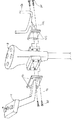
次に、図5について説明する。
前記パワステレバー8の前方に操作パネル9を設けるにあたり、パワステレバー8と操作パネル9との間には所定の隙間Lを設ける構成とする。この隙間Lは、作業者がパワステレバー8を充分に把持可能な距離とする。これにより、作業者が立ち作業をしたり緊急の場合において、パワステレバー8を上方から覆うように握れるので、操作性が向上するようになる。
【0031】
前述の図4に示しているように、パワステレバー8の後方であってこのパワステレバー8とともに一体的に移動する支持手段10を設ける構成とする。この支持手段10は、作業者がパワステレバー8を把持した状態で手首を支持するものである。もちろん、作業者がパワステレバー8を把持しない状態であっても、作業者の手首等を支持可能である。支持手段10の具体的構成は、支持プレート10aで支持されており、この支持プレート10aは、パワステレバー8に取り付けられている。また、支持手段10は棒状部材10bで構成され、しかも、棒状部材10bは載置した手首が左右方向に落ちないように左右の上方へ突出している。さらに、手首部分の形状に沿うようにわん曲している構成である。
【0032】
これにより、パワステレバー8を操作するときには、作業者の手首部分を支持手段10上に載置するので、疲れが少なくなり作業環境が向上する。特に、長時間パワステレバー8を操作し続けても疲れが少なくなり作業能率の低下を防止できるようになる。このように、作業者はパワステレバー8を把持し、手首を支持手段10上に載置した状態で操作パネル9のスイッチ類を操作できるので、運転が楽になり、作業能率が向上するようになる。
【0033】
次に、図6と図7について説明する。
前記操作パネル9と支持手段10とを、パワステレバー8に対して着脱自在に構成する。具体的には、操作パネル9はボルト68により着脱自在に構成され、支持手段10もボルト69で着脱自在に構成されている。これにより、組立てや保守管理が容易に実行可能となる。また、コンバインの仕様によりスイッチ類が増減するので、このような仕様の変化にも容易に対応可能となる。
【0034】
次に、図8について説明する。
操作パネル9を支持する支持プレート9側に長穴9bを設け、ボルト68を緩めることにより、操作パネル9が上下方向に位置調節自在に構成されている。また、支持手段10の支持プレート10a側にも長穴10cを設け、ボルト69を緩めることにより、支持手段10が上下方向に位置調節自在に構成されている。もちろん、このような上下方向の調節以外にも、例えば、左右方向や斜め方向にも位置調節自在に構成してもよい。これにより、操作パネル9と支持手段10は、作業状態や作業者の好みによりパワステレバー8に対して位置変更可能なので、作業に適した状態でパワステレバー8,操作パネル9及び支持手段10を操作でき、操作性が向上するようになる。
【0035】
次に、図9について説明する。
この図はパワステレバー8と操作パネル9の断面図を示している。前述のごとく、パワステレバー8の上面部8aには複数スイッチ類が設けられているので、電線70をパワステレバー8内の空間部71を通すように構成する。また、操作パネル9にも複数のスイッチ類が設けられているので、電線72を操作パネル9内の空間部73を通過させて、パワステレバー8内の空間部71へと配策するように構成する。これにより、前記電線70と電線72は外部に露出しないので、耐久性が向上し、また、外部からの保護が可能となる。
【図面の簡単な説明】
【図1】左側面図
【図2】右側面図
【図3】伝動機構線図
【図4】斜視図
【図5】左側面図
【図6】斜視図
【図7】左側面図
【図8】斜視図
【図9】断面図
【符号の説明】
1…走行装置、2…車台、3…脱穀装置、4…引起装置、5…刈取装置、6…グレンタンク、7…操作部、8…操向操作具、9…操作パネル、10…支持手段。[0001]
TECHNICAL FIELD OF THE INVENTION
The present invention relates to a combine and belongs to the technical field of agricultural machinery.
[0002]
[Prior art]
In the prior art, a steering operation tool for turning the combine right and left and moving the reaper up and down has a configuration in which various switches for performing operations of each part of the combine are provided on the upper part of the steering operation tool body (for example, And Patent Document 1.).
[0003]
[Patent Document 1]
Japanese Patent Application Laid-Open No. Hei 8-211956
[Problems to be solved by the invention]
In the above-described configuration, a switch is provided on the main body of the steering operation tool, so that the number of switches is limited. For this reason, even if the switch is frequently used, the switch cannot be provided on the main body of the steering operation tool. For this reason, switches are provided on the panel portion on the side of the worker, and the operation of the switch is easy. There was a disadvantage that it could not be done.
[0005]
[Means for Solving the Problems]
The present invention takes the following technical means in order to solve the above-mentioned problems. That is, according to the first aspect of the present invention, a threshing device 3 is provided above the undercarriage 2 having the traveling device 1, and in front of the threshing device 3, a plurality of raisings that cause multiple rows of planted grain culms are provided. An apparatus 4 and a harvesting device 5 for harvesting the culm caused by the raising device 4 and transporting the harvested stalk to the rear threshing device 3 are provided. On the right side of the threshing device 3, the grains selected by threshing by the threshing device 3 are provided. Is provided with a steering tank 8 in which a steering operation tool 8 is provided in front of the Glen tank 6, and a steering operation tool 8 is provided in the operation section 7. When the tilting is performed, the combine turns right and left, and when the steering operation tool 8 is tilted in the front-rear direction, the reaper 5 moves up and down, and an operation panel 9 that moves integrally with the steering operation tool 8 is provided. And a combine.
[0006]
According to the above configuration, when the steering operation tool 8 provided on the operation unit 7 is tilted leftward, the combine turns left, and when tilted rightward, the combine turns right. When the steering operation tool 8 is tilted forward, the reaper 5 is lowered, and when the steering tool 8 is tilted rearward, the reaper 5 is raised. When the steering operation tool 8 is tilted back and forth and left and right as described above, the operation panel 9 also moves forward and backward and left and right integrally with the steering operation tool 8.
[0007]
The invention according to claim 2 is characterized in that a support means 10 is provided behind the steering operation tool 8 to move integrally with the steering operation tool 8 to support a wrist of an operator. Item 9 is a combine according to item 1.
According to the above configuration, in addition to the operation of the first aspect, when the operator operates the steering operation tool 8, the operator holds the steering operation tool 8 with his / her hand and places the wrist portion on the support means 10. The steering operation tool 8 is operated back and forth and left and right. The support means 10 supporting the wrist also moves integrally with the wrist in the front, rear, left and right directions.
[0008]
According to the third aspect of the present invention, the operation panel 9 and the support means 10 are configured to be changeable in position with respect to the steering operation tool 8.
According to the above configuration, together with the operation of the second aspect, the operation panel 9 and the support means 10 change the position with respect to the steering operation tool 8 according to the work situation.
[0009]
【The invention's effect】
Since the present invention is configured as described above, according to the first aspect of the present invention, the operation panel 9 can be operated while operating the steering operation tool 8 in the front, rear, left and right directions, so that the operability is improved. Further, while the operator is driving the combine, the field of view of the operator is in front, but the operator can operate the operation panel 9 without looking away from the front field of view, so that a safe operation can be performed.
[0010]
According to the second aspect of the present invention, in addition to the effect of the first aspect, when operating the steering operation tool 8, the wrist portion of the operator is placed on the support means 10, so that fatigue is reduced and the working environment is improved. I do. In particular, even if the steering operation tool 8 is continuously operated for a long time, fatigue is reduced, and a decrease in work efficiency can be prevented.
[0011]
According to the third aspect of the present invention, in addition to the effect of the second aspect, the operation panel 9 and the support means 10 can be changed in position with respect to the steering operation tool 8 according to the work state or the preference of the worker, so that it is suitable for work. The steering operation tool 8 can be operated in the state, and the operability is improved.
[0012]
BEST MODE FOR CARRYING OUT THE INVENTION
1 and 2 show a combine embodying an embodiment of the present invention.
A mowing device 5 is provided in front of the chassis 2 having the traveling device 1. The cutting device 5 includes a weeding tool 11 for weeding the planted grain culm, a raising device 4 for causing the planted grain culm, a cutting blade 13 for cutting the planted grain culm, and a cutting blade 13 for cutting. There is provided a stock transfer device 14 for holding the harvested culm and transporting it backward. Behind the stock carrier 14, there is provided a supply carrier 15 that takes over and transports the grain stems conveyed from the stock carrier 14.
[0013]
The reaper 5 is supported by a reaper supporting frame 17 that moves up and down about a fulcrum above the traveling transmission device 16 at a substantially left and right intermediate portion thereof, and the reaper 5 is mounted together with the reaper supporting frame 17. It is configured to move up and down.
Above the undercarriage 2, a threshing device 3 having a feed chain 18 that takes over and transports the grain stalks conveyed from the supply and transport device 15, and a right side of the threshing device 3, A Glen tank 6 for temporarily storing the threshed-selected grains, and an operation unit 7 located in front of the Glen tank 6 and performing various operations of the combine are mounted.
[0014]
Behind the threshing device 3, there are a culm chain 12 that takes over and conveys the culm conveyed from the feed chain 18, and a cutter device 19 that cuts the culm below the end of the culm chain 12. Is provided. In addition, another working machine such as a knotter for binding the culm may be mounted behind the cutter device 19 of this embodiment.
[0015]
When the amount of grains in the Glen tank 6 becomes full, the grains are discharged from the fryer cylinder 20 and the grain discharge auger 21 to the outside of the machine. The hoisting cylinder 20 is configured to be rotatable by an electric motor (not shown), and is configured to be able to move up and down by a grain discharge auger 21 and a hydraulic cylinder 22. Since the grain discharge auger 21 is connected to the upper part of the fryer cylinder 20 and is integrally formed, when the fryer cylinder 20 turns, the grain discharge auger 21 also turns.
[0016]
When the harvesting operation is performed by moving such a combine forward, the culm planted in the field scene is weeded by the weeder 11 and then raised by the raising device 4 to the cutting blade 13. Reaping. After that, the paper is conveyed backward by the stock carrier 14 and transferred to the supply carrier 15. The cereal stem that has been taken over by the supply and transport device 15 is further transported backward. Then, the grain is transferred to the feed chain 18 of the threshing device 16 and the culm is threshed and sorted by the threshing device 3 while being conveyed backward by the feed chain 18.
[0017]
The husks selected in this way are transported from the first deep-frying cylinder 23 into the Glen tank 6 and temporarily stored therein. When the amount of grains stored in the Glen tank 6 becomes full, the operator is notified by the notification means (buzzer or display device) of the operation unit 7. Then, the operator interrupts the harvesting operation and starts the operation of discharging the grains in the Glen tank 6 to the outside of the machine. The combine is moved to an arbitrary position (position near the truck), the grain discharge auger 21 is separated from the auger receiver 24, and the grain discharge port 21a is moved to a position such as a truck bed. Then, the grain discharge lever 25 provided in the operation unit 7 is set to the ON state, and the grains in the Glen tank 6 are discharged to the outside of the machine. When the grain discharge in the Glen tank 6 is completed, the grain discharge auger 21 is stored in the auger receiver 24 again.
[0018]
The detailed configuration of the traveling transmission 16 will be described with reference to FIG. A pulley 26b, a pulley 26c, and a pulley 26d are attached to an output shaft 26a of the engine 26. When the pulley 26b is driven to rotate and the clutch is engaged, the lower spiral (not shown) in the Glen tank 6 is driven, and the grain is discharged from the grain discharge port 21a of the grain discharge auger 21 to the outside of the machine. It is a configuration that is discharged. When the pulley 26d is driven to rotate and a threshing clutch (not shown) is engaged, the threshing device 3 is driven. The pulley 26c is a pulley that drives the traveling transmission device 16.
[0019]
Power is transmitted from the pulley 26c to the input shaft 30 of the variable hydraulic pump 27a of the hydraulic continuously variable transmission 27 via the belt 28 and the pulley 29. By changing the inclination angle of the swash plate of the variable hydraulic pump 27a, the amount and direction of oil supply to the fixed hydraulic motor 27b is changed, and the number of revolutions and the direction of rotation of the output shaft 31 are changed. Reference numeral 32 denotes a fan fixed to the input shaft 30, and the wind generated by the fan 33 is blown toward the hydraulic continuously variable transmission 27 to cool the hydraulic continuously variable transmission 27.
[0020]
The power of the output shaft 31 is reduced and transmitted through the gears 34, 35, 36 and 37 in the bypass transmission case 33, and is transmitted to the input shaft 38 of the traveling transmission device 16. The input shaft 38 is provided with a moving body 39 having a gear 40 and a gear 41, and the moving body 39 moves in the longitudinal direction of the shaft 38. The gear 41 has a claw 49b, and the gear 42 also has a claw 49a. A gear 38 that does not move in the longitudinal direction is loosely fitted to the input shaft 38. Reference numeral 43 denotes a pulley for transmitting power to the reaper 5, which is fixed to the input shaft 38.
[0021]
A shaft 44 is provided on the lower side of the input shaft 38, and a gear 45, a gear 46, a gear 47 and a gear 48 are fixedly provided on the shaft 44. When the moving body 39 moves and the claw portion 49b of the gear 41 meshes with the claw portion 49a of the gear 42, the power of the input shaft 38 is transmitted to the shaft 44 at a low speed by the gear 42 and the gear 45. . When the moving body 39 moves and the gears 41 and 47 mesh with each other, the power of the input shaft 38 is transmitted at a medium speed by the gears 41 and 47 to the shaft 44. Further, when the moving body 39 moves and the gears 40 and 48 mesh with each other, the power of the input shaft 38 is transmitted at a high speed by the gears 40 and 48 to the shaft 44.
[0022]
In this manner, the rotational power transmitted to the shaft 44 is transmitted from the gear 46 fixed to the shaft 44 to the center gear 50 that is loosely fitted to the lower side clutch shaft 49. Since the lower side from the side clutch shaft 49 is symmetrical, the path on the right side will be described. A right moving body 51R is provided on the side clutch shaft 49 so as to be movable in the longitudinal direction. When the right moving body 51R is connected to the center gear 50, the power of the center gear 50 travels rightward from the gear 52R formed on the right moving body 51R via a gear 54R fixed to the right running shaft 53R. The configuration is such that the shaft 53R is driven to rotate. 55L and 55R are brakes provided at both ends of the side clutch shaft 49.
[0023]
The path on the left side below the side clutch shaft 49 indicates a state in which the straight traveling state is interrupted, the brake is applied to the left traveling shaft 53L, and the combine is turning in the left direction. That is, the left moving body 51L is disconnected from the center gear 50, and the left moving body 51L moves to the left to press the left brake 55L to stop the rotation of the left traveling shaft 53L. is there.
[0024]
Next, FIG. 4 will be described.
2 shows a specific configuration of a steering operation tool (hereinafter referred to as a power steering lever 8) provided in an operation unit 7. The power steering lever 8 is provided upright at the right end of the front panel 56 of the operation unit 7. When the power steering lever 8 is tilted rearward, the reaper 5 is raised, and when the power steering lever 8 is tilted forward, the reaper 5 is lowered. When the power steering lever 8 is tilted leftward, the connection between the left moving body 51L and the center gear 50 is disconnected, and the left brake 55L is actuated to turn the combine to the left. When the power steering lever 8 is tilted rightward, the connection between the right moving body 51R and the center gear 50 is disconnected, and the right brake 55R is operated to turn the combine rightward.
[0025]
A traveling speed change lever 62 for changing the forward / reverse of the combine and the vehicle speed is provided on a left panel 61 of the operation unit 7. When the traveling speed change lever 62 is moved forward, the swash plate of the hydraulic motor 27 of the hydraulic continuously variable transmission 27 tilts to the forward rotation side, and the combine moves forward. In this configuration, the swash plate of the hydraulic motor 27 of the continuously variable transmission 27 tilts in the reverse rotation direction, and the combine moves backward. The vehicle speed of the combine in the forward direction and the vehicle speed in the reverse direction are determined by the amount of movement of the traveling shift lever 62.
[0026]
A plurality of switches are provided on the upper surface 8a of the power steering lever 8. The switches may be of any type. Usually, when the left switch 57 is pressed, the chassis 2 tilts to the left, and when the right switch 58 is pressed, the chassis 22 tilts to the right. When the front switch 59 is pressed, the chassis 2 tilts forward, and when the rear switch 60 is pressed, the chassis 2 tilts rearward. When the front switch 59 and the rear switch 60 are operated, the lowering and the raising of the reaper 5 may be executed, respectively. As described above, when the switches are provided on the upper surface portion 8a of the power steering lever 8, the switches can be operated while operating the power steering lever 8, thereby facilitating the operating operation of the combine.
[0027]
However, since the area of the upper surface portion 8a is small, the number of switches arranged is limited. Therefore, in the related art, since another switch is disposed in the left panel 61 of the operation unit 7, the operability is poor. In particular, in the combine, since the power steering lever 8 is gripped by the right hand and the travel shift lever 62 is gripped by the left hand, when operating switches provided on the left panel 61, the left hand must be released from the travel shift lever 62. Therefore, when operating switches on the left panel 61, there is a disadvantage that the vehicle speed of the combine cannot be changed.
[0028]
Therefore, as shown in FIG. 4, an operation panel 9 that moves integrally with the power steering lever 8 is provided in front of the power steering lever 8. The operation panel 9 is supported by a support stay 9a. The operation panel 9 includes an automatic directional control switch 63 for automatically moving the combine along the culm row, an automatic handling depth switch 64 for automatically adjusting the handling depth in the threshing device, and the chassis 2. An automobile body horizontal switch 65 for automatically maintaining the horizontal state, an automatic cutting height switch 66 for automatically adjusting the cutting height of the cutting device 5, and a manual depth for manually adjusting the handling depth in the threshing device. Switch 67 is provided. These switches are frequently used by the combine during the harvesting operation.
[0029]
As described above, since the operation panel 9 is provided in front of the power steering lever 8 and a switch that is frequently used is provided on the operation panel 9, the operator grips the power steering lever 8 with the right hand and shifts the traveling speed with the left hand. The switch group on the operation panel 9 can be easily operated while holding the lever 62, that is, while operating the combine. Further, since the operation panel 9 can be operated while operating the power steering lever 8 in the front, rear, left and right directions, operability is improved. Further, while the operator is driving the combine, the field of view of the operator is in front, but the operator can operate the operation panel 9 without looking away from the front field of view, so that a safe operation can be performed.
[0030]
Next, FIG. 5 will be described.
When the operation panel 9 is provided in front of the power steering lever 8, a predetermined gap L is provided between the power steering lever 8 and the operation panel 9. The gap L is a distance that allows the operator to sufficiently grip the power steering lever 8. Accordingly, the operator can grip the power steering lever 8 so as to cover the power steering lever 8 from above in the case of standing work or in an emergency, thereby improving operability.
[0031]
As shown in FIG. 4, the support means 10 is provided behind the power steering lever 8 and moves integrally with the power steering lever 8. The support means 10 supports the wrist while the operator holds the power steering lever 8. Of course, even when the worker does not grip the power steering lever 8, the wrist or the like of the worker can be supported. The specific configuration of the support means 10 is supported by a support plate 10 a, which is attached to the power steering lever 8. The support means 10 is composed of a rod-shaped member 10b, and the rod-shaped member 10b protrudes right and left upward so that the placed wrist does not fall in the left-right direction. Furthermore, it is configured to bend along the shape of the wrist.
[0032]
Thus, when the power steering lever 8 is operated, the wrist of the operator is placed on the support means 10, so that fatigue is reduced and the working environment is improved. In particular, even if the power steering lever 8 is continuously operated for a long time, fatigue is reduced, and a decrease in work efficiency can be prevented. In this way, the operator can operate the switches on the operation panel 9 while holding the power steering lever 8 and placing the wrist on the support means 10, so that driving becomes easier and work efficiency is improved. .
[0033]
Next, FIGS. 6 and 7 will be described.
The operation panel 9 and the support means 10 are configured to be detachable from the power steering lever 8. Specifically, the operation panel 9 is configured to be detachable by bolts 68, and the support means 10 is also configured to be detachable by bolts 69. As a result, assembly and maintenance management can be easily performed. Further, since the number of switches increases or decreases according to the specifications of the combine, it is possible to easily cope with such a change in the specifications.
[0034]
Next, FIG. 8 will be described.
An elongated hole 9b is provided on the support plate 9 side for supporting the operation panel 9, and the position of the operation panel 9 can be adjusted vertically by loosening bolts 68. The support means 10 is also provided with a long hole 10c on the support plate 10a side of the support means 10 and a bolt 69 is loosened so that the position of the support means 10 can be adjusted vertically. Of course, in addition to such vertical adjustment, for example, the position may be freely adjustable in the horizontal direction or in the oblique direction. As a result, the operation panel 9 and the support means 10 can be changed in position with respect to the power steering lever 8 according to the working state and the preference of the operator, so that the power steering lever 8, the operation panel 9 and the supporting means 10 can be operated in a state suitable for the work. Operability is improved.
[0035]
Next, FIG. 9 will be described.
This figure shows a sectional view of the power steering lever 8 and the operation panel 9. As described above, since a plurality of switches are provided on the upper surface 8 a of the power steering lever 8, the electric wire 70 is configured to pass through the space 71 in the power steering lever 8. Further, since the operation panel 9 is also provided with a plurality of switches, the configuration is such that the electric wires 72 pass through the space 73 in the operation panel 9 and are routed to the space 71 in the power steering lever 8. I do. Thereby, since the electric wires 70 and the electric wires 72 are not exposed to the outside, the durability is improved and the protection from the outside is possible.
[Brief description of the drawings]
FIG. 1 is a left side view. FIG. 2 is a right side view. FIG. 3 is a transmission mechanism diagram. FIG. 4 is a perspective view. FIG. 5 is a left side view. FIG. 6 is a perspective view. 8: perspective view [FIG. 9] sectional view [explanation of reference numerals]
DESCRIPTION OF SYMBOLS 1 ... Running apparatus, 2 ... chassis, 3 ... Threshing apparatus, 4 ... Raising apparatus, 5 ... Harvesting apparatus, 6 ... Glen tank, 7 ... Operation part, 8 ... Steering operation tool, 9 ... Operation panel, 10 ... Support means .