JP2004088729A - Digital camera system - Google Patents
Digital camera system Download PDFInfo
- Publication number
- JP2004088729A JP2004088729A JP2003104965A JP2003104965A JP2004088729A JP 2004088729 A JP2004088729 A JP 2004088729A JP 2003104965 A JP2003104965 A JP 2003104965A JP 2003104965 A JP2003104965 A JP 2003104965A JP 2004088729 A JP2004088729 A JP 2004088729A
- Authority
- JP
- Japan
- Prior art keywords
- digital camera
- cradle
- camera
- signal
- mode
- Prior art date
- Legal status (The legal status is an assumption and is not a legal conclusion. Google has not performed a legal analysis and makes no representation as to the accuracy of the status listed.)
- Pending
Links
- 230000008859 change Effects 0.000 claims abstract description 14
- 238000001514 detection method Methods 0.000 claims description 36
- 230000007246 mechanism Effects 0.000 claims description 23
- 230000006854 communication Effects 0.000 claims description 15
- 238000004891 communication Methods 0.000 claims description 15
- 230000007274 generation of a signal involved in cell-cell signaling Effects 0.000 claims 1
- 230000006870 function Effects 0.000 description 28
- 238000012545 processing Methods 0.000 description 11
- 238000003384 imaging method Methods 0.000 description 7
- 238000009434 installation Methods 0.000 description 5
- 238000000034 method Methods 0.000 description 4
- 238000012546 transfer Methods 0.000 description 4
- 230000006835 compression Effects 0.000 description 3
- 238000007906 compression Methods 0.000 description 3
- 238000010586 diagram Methods 0.000 description 3
- 239000004973 liquid crystal related substance Substances 0.000 description 3
- 239000000428 dust Substances 0.000 description 2
- 238000009825 accumulation Methods 0.000 description 1
- 230000008901 benefit Effects 0.000 description 1
- 230000007175 bidirectional communication Effects 0.000 description 1
- 230000008602 contraction Effects 0.000 description 1
- 238000012937 correction Methods 0.000 description 1
- 230000000694 effects Effects 0.000 description 1
- 230000003287 optical effect Effects 0.000 description 1
- 230000002093 peripheral effect Effects 0.000 description 1
- 229920001690 polydopamine Polymers 0.000 description 1
- 238000003825 pressing Methods 0.000 description 1
- 230000008569 process Effects 0.000 description 1
- 230000001681 protective effect Effects 0.000 description 1
- 238000001454 recorded image Methods 0.000 description 1
- 230000004044 response Effects 0.000 description 1
Images

Classifications
-
- H—ELECTRICITY
- H04—ELECTRIC COMMUNICATION TECHNIQUE
- H04N—PICTORIAL COMMUNICATION, e.g. TELEVISION
- H04N1/00—Scanning, transmission or reproduction of documents or the like, e.g. facsimile transmission; Details thereof
- H04N1/00127—Connection or combination of a still picture apparatus with another apparatus, e.g. for storage, processing or transmission of still picture signals or of information associated with a still picture
- H04N1/00204—Connection or combination of a still picture apparatus with another apparatus, e.g. for storage, processing or transmission of still picture signals or of information associated with a still picture with a digital computer or a digital computer system, e.g. an internet server
-
- H—ELECTRICITY
- H04—ELECTRIC COMMUNICATION TECHNIQUE
- H04N—PICTORIAL COMMUNICATION, e.g. TELEVISION
- H04N23/00—Cameras or camera modules comprising electronic image sensors; Control thereof
-
- H—ELECTRICITY
- H04—ELECTRIC COMMUNICATION TECHNIQUE
- H04N—PICTORIAL COMMUNICATION, e.g. TELEVISION
- H04N1/00—Scanning, transmission or reproduction of documents or the like, e.g. facsimile transmission; Details thereof
- H04N1/00127—Connection or combination of a still picture apparatus with another apparatus, e.g. for storage, processing or transmission of still picture signals or of information associated with a still picture
- H04N1/00204—Connection or combination of a still picture apparatus with another apparatus, e.g. for storage, processing or transmission of still picture signals or of information associated with a still picture with a digital computer or a digital computer system, e.g. an internet server
- H04N1/00236—Connection or combination of a still picture apparatus with another apparatus, e.g. for storage, processing or transmission of still picture signals or of information associated with a still picture with a digital computer or a digital computer system, e.g. an internet server using an image reading or reproducing device, e.g. a facsimile reader or printer, as a local input to or local output from a computer
- H04N1/00241—Connection or combination of a still picture apparatus with another apparatus, e.g. for storage, processing or transmission of still picture signals or of information associated with a still picture with a digital computer or a digital computer system, e.g. an internet server using an image reading or reproducing device, e.g. a facsimile reader or printer, as a local input to or local output from a computer using an image reading device as a local input to a computer
-
- H—ELECTRICITY
- H04—ELECTRIC COMMUNICATION TECHNIQUE
- H04N—PICTORIAL COMMUNICATION, e.g. TELEVISION
- H04N1/00—Scanning, transmission or reproduction of documents or the like, e.g. facsimile transmission; Details thereof
- H04N1/32—Circuits or arrangements for control or supervision between transmitter and receiver or between image input and image output device, e.g. between a still-image camera and its memory or between a still-image camera and a printer device
- H04N1/32496—Changing the task performed, e.g. reading and transmitting, receiving and reproducing, copying
-
- H—ELECTRICITY
- H04—ELECTRIC COMMUNICATION TECHNIQUE
- H04N—PICTORIAL COMMUNICATION, e.g. TELEVISION
- H04N23/00—Cameras or camera modules comprising electronic image sensors; Control thereof
- H04N23/60—Control of cameras or camera modules
- H04N23/66—Remote control of cameras or camera parts, e.g. by remote control devices
-
- H—ELECTRICITY
- H04—ELECTRIC COMMUNICATION TECHNIQUE
- H04N—PICTORIAL COMMUNICATION, e.g. TELEVISION
- H04N23/00—Cameras or camera modules comprising electronic image sensors; Control thereof
- H04N23/60—Control of cameras or camera modules
- H04N23/667—Camera operation mode switching, e.g. between still and video, sport and normal or high- and low-resolution modes
-
- H—ELECTRICITY
- H04—ELECTRIC COMMUNICATION TECHNIQUE
- H04N—PICTORIAL COMMUNICATION, e.g. TELEVISION
- H04N2101/00—Still video cameras
-
- H—ELECTRICITY
- H04—ELECTRIC COMMUNICATION TECHNIQUE
- H04N—PICTORIAL COMMUNICATION, e.g. TELEVISION
- H04N2201/00—Indexing scheme relating to scanning, transmission or reproduction of documents or the like, and to details thereof
- H04N2201/0008—Connection or combination of a still picture apparatus with another apparatus
- H04N2201/0034—Details of the connection, e.g. connector, interface
- H04N2201/0048—Type of connection
- H04N2201/0058—Docking-station, cradle or the like
Landscapes
- Engineering & Computer Science (AREA)
- Multimedia (AREA)
- Signal Processing (AREA)
- General Engineering & Computer Science (AREA)
- Computing Systems (AREA)
- Studio Devices (AREA)
- Accessories Of Cameras (AREA)
Abstract
Description
【0001】
【発明の属する技術分野】
本発明はデジタルカメラシステムに係り、特にクレードルを介してデジタルカメラがパーソナルコンピュータ等の外部機器に接続されるデジタルカメラシステムに関する。
【0002】
【従来の技術】
デジタルカメラは、パーソナルコンピュータと接続することができ、これにより撮影した画像データをパーソナルコンピュータに取り込むことができる。
【0003】
パーソナルコンピュータとデジタルカメラの接続には、一般にケーブルが用いられる。しかし、ケーブルによる接続は煩わしく、手間がかかるという欠点があった。
【0004】
そこで、このパーソナルコンピュータとデジタルカメラの接続作業をより簡単にできるようにするべく、クレードルを用いてデジタルカメラとパーソナルコンピュータを接続するカメラシステムが提案されている(特願2001−8067号明細書)。このシステムはパーソナルコンピュータにケーブルを介して接続されたクレードルにデジタルカメラを装着することで、デジタルカメラとパーソナルコンピュータとを接続可能にしたものである。
【0005】
また、近年、デジタルカメラは、パーソナルコンピュータとの通信モードとして、デジタルカメラをカードリーダとして機能させるストレージモードと、PCカメラとして機能させるPCカメラモードとがあり、ストレージモードの場合には、メモリーカードに記録された画像データを適宜読み出してパーソナルコンピュータに送信し、PCカメラモードの場合には、ビデオ会議等が可能なように現在撮影中の動画データを連続的にパーソナルコンピュータに送信する。
【0006】
【発明が解決しようとする課題】
しかしながら、従来のクレードルを用いたカメラシステムでは、パーソナルコンピュータとの通信モードの設定をカメラ側で行うようにされており、通信モードを設定してからデジタルカメラをクレードルに装着しなければならず、操作性が悪いという欠点があった。また、カメラ側の設定を確認しないと現在の通信モードの設定状態が分からないという欠点もあった。
【0007】
本発明はこのような事情に鑑みてなされたもので、操作性のよいデジタルカメラシステムを提供することを目的とする。
【0008】
【課題を解決するための手段】
本発明は前記目的を達成するために、デジタルカメラと、前記デジタルカメラが装着されるクレードルと、からなるデジタルカメラシステムにおいて、前記クレードルは、可動部と、前記可動部の位置に応じて前記デジタルカメラの機能を変更する指令信号を生成する信号生成手段と、前記信号生成手段で生成された前記指令信号を前記デジタルカメラに供給する信号伝達手段と、を備え、前記デジタルカメラは、前記クレードルの可動部の位置に応じて生成される指令信号を受け入れる信号受入手段と、前記クレードルから供給された前記指令信号に基づいて動作モードを変更するモード制御手段と、を備えていることを特徴とする。
【0009】
本発明によれば、クレードルの可動部を動かすと、その可動部の位置が検出され、可動部の位置に応じた指令信号が生成される。この指令信号は、クレードルに装着されているデジタルカメラに送られ、指令信号に従ってデジタルカメラの動作モード(すなわち、機能)が切り替えられる。これにより、煩わしい設定作業が不要になり、操作性が向上する。
【0010】
ここでいう「デジタルカメラ」という用語は、被写体の光学像をデジタル画像データに変換する機能を備えた電子撮像装置を表すものであり、デジタルスチルカメラ、デジタルビデオカメラなど「カメラ」という製品分類に属するものが含まれることはもちろんのこと、これに属さない製品であってもカメラ付き携帯電話機、カメラ付きPDA、カメラ付きモバイルパソコンなどのように、実質的に同様の機能を搭載した機器についても「デジタルカメラ」の概念に含まれるものとする。
【0011】
本発明のカメラシステムに用いられるクレードルの一態様によれば、前記可動部は、デジタルカメラが装着されるカメラ装着部であることを特徴としている。この態様ではデジタルカメラをクレードルのカメラ装着部に載せたままの状態でデジタルカメラとともにカメラ装着部を動かすことができる。
【0012】
また、他の態様に係るクレードルは、前記カメラ装着部と、前記カメラ装着部を支持する脚部と、を含み、前記カメラ装着部は可動機構を介して前記脚部と連結されていることを特徴とする。
【0013】
この場合、更に他の態様によれば、前記可動機構は、前記カメラ装着部を前記脚部に対して相対的に移動させるものであり、その移動形態には、傾動、スライド、回転及び上下動のうち少なくとも1つが含まれるものとする。
【0014】
また、前記可動機構の構造として、一定の可動範囲内で前記可動部を移動させ得るものであることが好ましい。デジタルカメラ側で変更し得る動作モードの種類に対応させて可動部の停止位置が定められる。2種類のモードを切り替える場合においては、停止位置は可動範囲内で少なくとも2カ所設定される。
【0015】
本発明によるクレードルの他の態様は、外部機器と通信可能に接続するための通信インターフェースを備え、該クレードルに前記デジタルカメラを装着することによって該デジタルカメラは当該クレードルを経由して外部機器と通信可能に接続されることを特徴とする。
【0016】
この場合、前記信号生成手段は、前記クレードルを介して通信可能に接続された前記外部機器に対する前記デジタルカメラの機能を切り替える信号を生成することを特徴とする。
【0017】
本発明のカメラシステムに用いられるデジタルカメラの一態様によれば、前記クレードルに装着され、かつ、カメラ電源オンの状態のときに、前記指令信号に基づく動作モードの変更が行われることを特徴とする。
【0018】
更に他の態様に係るデジタルカメラは、カメラ電源オフの状態で前記クレードルに装着されたときには、前記クレードルを介して供給される電力によってカメラ内の電池を充電する充電モードに自動設定する充電制御手段を備えていることを特徴とする。
【0019】
また、本発明の他の態様は前記目的を達成するために、クレードルに装着することでデジタルカメラが外部機器と通信可能に接続されるデジタルカメラシステムにおいて、前記クレードルは、装着されたデジタルカメラのアオリ角度を変更するアオリ角度変更手段と、前記アオリ角度変更手段による前記デジタルカメラのアオリ角度の変更を検出する検出手段と、前記検出手段の検出結果に基づいて前記デジタルカメラに機能変更信号を出力する指令手段とを備え、前記デジタルカメラは、前記指令手段からの機能変更信号に基づいて前記外部機器に対する機能を変更することを特徴とするデジタルカメラシステムを提供する。
【0020】
本発明によれば、クレードルに装着したデジタルカメラのアオリ角度に応じて外部機器に対するデジタルカメラの機能が切り替えられる。これにより、煩わしい設定作業が不要になり、操作性が向上する。また、クレードルに装着されたデジタルカメラのアオリ角度により一目で現在の設定状態を確認することができる。
【0021】
また、本発明の更に他の態様は前記目的を達成するために、クレードルに装着することでデジタルカメラが外部機器と通信可能に接続されるデジタルカメラシステムにおいて、前記クレードルは、前記デジタルカメラを表裏いずれの方向からも装着可能な装着部と、前記装着部に装着された前記デジタルカメラの向きを検出する検出手段と、前記検出手段の検出結果に基づいて前記デジタルカメラに機能変更信号を出力する指令手段とを備え、前記デジタルカメラは、前記指令手段からの機能変更信号に基づいて前記外部機器に対する機能を変更することを特徴とするデジタルカメラシステムを提供する。
【0022】
本発明によれば、クレードルに装着したデジタルカメラの向きに応じて外部機器に対するデジタルカメラの機能が切り替えられる。これにより、煩わしい設定作業が不要になり、操作性が向上する。また、クレードルに装着されたデジタルカメラの向きにより一目で現在の設定状態を確認することができる。
【0023】
また、本発明の他の態様は、前記目的を達成するために、クレードルに装着することでデジタルカメラが外部機器と通信可能に接続されるデジタルカメラシステムにおいて、前記クレードルは、前記デジタルカメラを表裏いずれの方向からも装着可能な装着部を有する一方、前記デジタルカメラは、前記クレードルの装着部に装着された向きを検出する検出手段を有し、該検出手段の検出結果に基づいて前記外部機器に対する機能が変更されることを特徴とするデジタルカメラシステムを提供する。
【0024】
本発明によれば、クレードルに装着したデジタルカメラの向きに応じて外部機器に対するデジタルカメラの機能が切り替えられる。これにより、煩わしい設定作業が不要になり、操作性が向上する。また、クレードルに装着されたデジタルカメラの向きにより一目で現在の設定状態を確認することができる。
【0025】
【発明の実施の形態】
以下、添付図面に従って本発明に係るデジタルカメラシステムの好ましい実施の形態について説明する。
【0026】
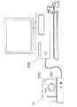
図1は本発明に係るデジタルカメラシステムの第1の実施形態を示す斜視図である。同図に示すように、本実施の形態のデジタルカメラシステムは、デジタルカメラ10とクレードル100とで構成され、クレードル100は、パーソナルコンピュータ200と双方向通信可能な通信ケーブル(本実施の形態ではUSBケーブル)210で接続される。
【0027】
図2、図3は、それぞれデジタルカメラ10とクレードル100の外観を示す正面図と背面図である。
【0028】
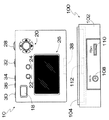
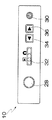
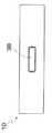
デジタルカメラ10の正面には、図2に示すように、撮影レンズ12、ストロボ14、ファインダー窓16等が設けられており、背面には、図3に示すように、ファインダー18、十字ボタン20、メニュー/OKボタン22、キャンセルボタン24、液晶モニタ26等が設けられている。また、デジタルカメラ10の上面には、図4に示すように、シャッターボタン28、電源ボタン30、モードスイッチ32、再生送りボタン34、再生戻しボタン36が設けられ、底面には、図5に示すように、中央位置にカメラコネクタ38が設けられている。
【0029】
デジタルカメラ10の上面に設けられたモードスイッチ32は、カメラのモードの切替スイッチとして機能する。デジタルカメラ10は、このモードスイッチ32をスライド操作することにより撮影モード又は再生モードに設定される。また、デジタルカメラ10の上面に設けられた再生送りボタン34と再生戻しボタン36は、再生モード時に再生画像の送りと戻しを指示するボタンとして機能する。
【0030】
一方、デジタルカメラ10の背面に設けられた十字ボタン20は、それぞれ対応する4方向の指示を入力するボタンとして機能し、この十字ボタン20でメニュー画面からメニュー項目を選択したり、各メニューから各種設定項目を選択する。また、メニュー/OKボタン22は、メニュー画面の表示及び選択内容の確定、実行などに使用され、キャンセルボタン24は、メニューから選んだ項目の取消や一つ前の操作状態に戻らせる時などに使用される。液晶モニタ26は、撮影した画像の再生用モニタとして使用されるとともに、メニューの表示画面として使用される。また、撮影モード時には、画角確認用の電子ビューファインダーとして使用される。
【0031】
クレードル100は、図2、図3、図6に示すように、主としてクレードル本体102と、クレードル本体102に揺動自在に支持されたカメラ装着部104とで構成されている。
【0032】
クレードル本体102は上面に凹部106が形成されており、この凹部106内にデジタルカメラ10が装着されるカメラ装着部104が収容配置されている。また、このクレードル本体102の正面には、図2に示すように、電源ボタン30が設けられており、背面には、図3に示すように、DCジャック108とUSBジャック110が設けられている。
【0033】
カメラ装着部104は、デジタルカメラ10の底部が嵌合可能な四角い皿状に形成されており、その底面中央にクレードルコネクタ112が設けられている。デジタルカメラ10をカメラ装着部104に装着すると、デジタルカメラ10底面に設けられたカメラコネクタ38が、このクレードルコネクタ112に接続される。
【0034】
カメラ装着部104の下部には軸受部材114が設けられており、軸受部材114は凹部106内に設けられたシャフト118に軸支されている。カメラ装着部104は、このシャフト118を中心に凹部106内を揺動する。
【0035】
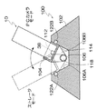
ここで、クレードル本体102の凹部106の前内壁面106Aと後内壁面106Bは、それぞれ所定角度傾斜して形成されており、揺動自在に支持されたカメラ装着部104は、この前内壁面106Aと後内壁面106Bに当接して係止される。そして、カメラ装着部104が、この前内壁面106Aと後内壁面106Bに係止されることにより、カメラ装着部104に装着されたデジタルカメラ10がクレードル100の設置面に対して所定角度傾斜した状態で保持される。この際、デジタルカメラ10は、図6に破線で示すように、カメラ装着部104が、凹部106の前内壁面106Aに係止されることにより、前側に傾斜した状態で保持され、同図に実線で示すように、後内壁面106Bに係止されることにより後側に傾斜した状態で保持される。これにより、アオリ角が変化する。
【0036】
また、この凹部106の前内壁面106Aと後内壁面106Bには、それぞれ前スイッチ122Aと後スイッチ122Bが設けられており、各スイッチはカメラ装着部104が各内壁面に当接することでオンになり、離れることでオフとなる。すなわち、前スイッチ122Aは、カメラ装着部104が前内壁面106Aに当接することで、カメラ装着部104の前面に押されてオンになり、後スイッチ122Bは、カメラ装着部104が後内壁面106Bに当接することで、カメラ装着部104の背面に押されてオンになる。この前スイッチ122Aと後スイッチ122Bからのオン/オフ信号はスイッチ検出回路124に出力され、スイッチ検出回路124は、この前スイッチ122Aと後スイッチ122Bからのオン/オフ信号を入力することにより、現在のデジタルカメラ10の保持状態を検出する。
【0037】
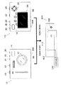
図7はデジタルカメラ10とクレードル100の内部回路の概略を示すブロック図である。
【0038】
同図に示すように、デジタルカメラ10は、撮像部52と信号処理部54とで構成されている。撮像部52は、撮影レンズ12、絞り58、固体撮像素子60を備えており、信号処理部54からの指示に基づいて被写体を撮像する。固体撮像素子60は、例えばCCDで構成され、CCDは、その受光面における電荷の蓄積、転送、排出の一連の動作によって画像を撮像する。
【0039】
信号処理部54は、システムコントローラ62の制御の下、撮像部52からの画像信号をアンプ64を介して取り込み、A/D変換器66でデジタル信号に変換する。そして、デジタル信号処理部68で所定の信号処理(ホワイトバランス調整、ガンマ補正、色差信号処理など)を施したのち、圧縮処理部70で圧縮処理する。圧縮されたデジタル画像データは、メモリーコントローラ80を介してカードスロットに装填されたメモリーカード82に記録される。
【0040】
クレードル100の電源ボタン30、DCジャック108、USBジャック110、スイッチ検出回路124は、それぞれクレードルコネクタ112内の対応する端子と配線を介して直接接続されている。
【0041】
デジタルカメラ10をクレードル100に装着すると、クレードル100のUSBジャック110は、クレードルコネクタ112とカメラコネクタ38を介してデジタルカメラ10のUSBコントローラ72に接続される。システムコントローラ62は、カメラ電源がオン状態のときにUSB接続を確認すると、カメラの動作モードを自動的にUSBモードにし、USBコントローラ72を介してパーソナルコンピュータ200とUSB通信を開始する。
【0042】
また、DCジャック108は、クレードルコネクタ112とカメラコネクタ38を介してデジタルカメラ10内の充電回路及びスイッチ回路74に接続される。したがって、DCジャック108にACアダプタ(不図示)から直流電源が供給されると、この直流電源は充電回路及びスイッチ回路74に供給される。充電回路及びスイッチ回路74は、カメラ電源がオフ状態のときに直流電源が供給されると、充電電池76への充電動作を開始し、充電電池76が満充電されると、充電動作を停止する。一方、充電回路及びスイッチ回路74は、カメラ電源がオン状態のときには上記充電動作は行わず、システムコントローラ62からの指令によってDC入力端子から入力する直流電源をDC−DCコンバータ78に供給するように切り替える。DC−DCコンバータ78は、入力する直流電源からカメラの各回路によって要求される各種の電圧電源を生成し、カメラ内の各回路に供給する。
【0043】
また、スイッチ検出回路124は、クレードルコネクタ112とカメラコネクタ38を介してシステムコントローラ62にクレードル100に装着されたデジタルカメラ10の保持状態を示す検出信号を出力する。
【0044】
ところで、上記のように、デジタルカメラ10のシステムコントローラ62は、カメラ電源がオン状態のときにUSB接続を確認すると、カメラの動作モードを自動的にUSBモードにするが、このUSBモードに設定されると、デジタルカメラ10は、接続されたパーソナルコンピュータ200に対して2種類の異なるデバイスクラスの機器として機能する。
【0045】
すなわち、デジタルカメラ10は、カメラ内のメモリーカード82を読み書きするカードリーダとして機能するストレージモードと、テレビ会議などに利用できるように撮影中の映像信号をリアルタイムで送出するPCカメラとして機能するPCカメラモードとを有している。
【0046】
そして、デジタルカメラ10は、このUSBモード下におけるストレージモードとPCカメラモードのモード選択をクレードル100に装着されたデジタルカメラ10のアオリ角度により行う。すなわち、デジタルカメラ10のシステムコントローラ62は、スイッチ検出回路124からの入力信号により前方に倒されていることを検知するとストレージモードに切り替え、後方に倒されていることを検知するとPCカメラモードに切り替える。
【0047】
このように、本実施の形態のデジタルカメラシステムでは、クレードルに装着したデジタルカメラ10のアオリ角度を変えることにより、ストレージモードとPCカメラモードとを自動で切り替えることができる。これにより、カメラ側で設定する手間が省け、操作性が向上する。
【0048】
また、ユーザーは、クレードルに装着されたデジタルカメラ10の姿勢を見るだけで、現在の設定モードを確認することができる。
【0049】
なお、デジタルカメラ10のアオリ角度の切り替えの検出方法は、上記の実施の形態のものに限定されるものではなく、他の機構を用いて検出するようにしてもよい。
【0050】
図8は、本発明に係るデジタルカメラシステムの第2の実施形態のデジタルカメラ10とクレードル300の外観を示す正面図である。
【0051】
同図に示すように、本実施の形態のデジタルカメラシステムでは、デジタルカメラ10がクレードル300に対して表裏いずれの方向からも装着できるようにされている。そして、このクレードル300に装着されたデジタルカメラ10の向きによってUSB接続されたデジタルカメラ10のストレージモードとPCカメラモードとが切り替えられる。
【0052】
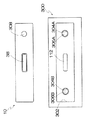
クレードル300は、上面部にデジタルカメラ10が装着される装着部302が形成されており、この装着部302の底面中央にクレードルコネクタ112が設けられている。
【0053】
また、この装着部302の底面には、図8及び図9に示すように、クレードルコネクタ112を挟んで左右対称位置に一対の穴304A、304Bが形成されており、各穴304A、304Bには、それぞれスイッチ306A、306Bが設けられている。
【0054】
一方、デジタルカメラ10の底面には、図8及び図9に示すように、正面から見て右側位置に突起308が形成されている。この突起308は、デジタルカメラ10の表側を前にしてクレードル300に装着すると、クレードル300の右側の穴304Aに嵌合し、右側のスイッチ306Aを押圧する。また、デジタルカメラ10の裏側を前にしてクレードル300に装着すると、クレードル300の左側の穴304Bに嵌合し、左側のスイッチ306Bを押圧する。
【0055】
各スイッチ306A、306Bは、突起308に押圧されることによりオンとなり、離れることでオフとなる。このスイッチ306A、306Bのオン/オフ信号はスイッチ検出回路124に出力される。スイッチ検出回路124は、このスイッチ306A、306Bからのオン/オフ信号を入力することにより、現在のデジタルカメラ10の保持状態(裏か表か)を検出する。そして、クレードルコネクタ112とカメラコネクタ38を介してデジタルカメラ10のシステムコントローラ62にクレードル300に装着されたデジタルカメラ10の保持状態を示す検出信号を出力する。
【0056】
なお、クレードルには、電源スイッチ、DCジャック、USBジャック等が設けられている点は上記第1の実施形態のクレードル100と同じである。また、デジタルカメラ10をクレードル300に装着すると、クレードル300のUSBジャックが、クレードルコネクタ112とカメラコネクタ38を介してデジタルカメラ10のUSBコントローラ72に接続され、DCジャックがクレードルコネクタ112とカメラコネクタ38を介してデジタルカメラ10内の充電回路及びスイッチ回路74に接続される点も同じである。
【0057】
以上のように構成された第2の実施形態のデジタルカメラシステムによれば、表面を前にしてデジタルカメラ10をクレードルに装着すると、デジタルカメラ10の底面に設けられた突起308が、クレードル300の右側の穴304Aに嵌合し、右側のスイッチ306Aがオンになる。
【0058】
スイッチ検出回路124は、この右側のスイッチ306Aからのオン信号を入力することにより、デジタルカメラ10が表向きに装着されたことを検出し、デジタルカメラ10のシステムコントローラ62にカメラのモードをPCカメラモードに設定する信号を出力する。デジタルカメラ10のシステムコントローラ62は、このスイッチ検出回路124からの入力信号によりデジタルカメラ10のモードをPCカメラモードに設定する。
【0059】
一方、裏面を前にしてデジタルカメラ10をクレードルに装着すると、デジタルカメラ10の底面に設けられた突起308が、クレードル300の左側の穴304Bに嵌合し、左側のスイッチ306Bがオンになる。
【0060】
スイッチ検出回路124は、この左側のスイッチ306Bからのオン信号を入力することにより、デジタルカメラ10が裏向きに装着されたことを検出し、デジタルカメラ10のシステムコントローラ62にカメラのモードをストレージモードに設定する信号を出力する。デジタルカメラ10のシステムコントローラ62は、このスイッチ検出回路124からの入力信号によりデジタルカメラ10のモードをストレージモードに設定する。
【0061】
このように、本実施の形態のデジタルカメラシステムにおいても、クレードルに装着するデジタルカメラ10の向きによってストレージモードとPCカメラモードとを自動で切り替えることができる。これにより、カメラ側で設定する手間が省け、操作性が向上する。
【0062】
また、ユーザーは、クレードルに装着されたデジタルカメラ10の向きを見るだけで、現在の設定モードを確認することができる。
【0063】
なお、デジタルカメラ10の装着方向の検出機構は、上記の実施の形態のものに限定されるものではなく、他の機構を用いて検出するようにしてもよい。
【0064】
また、本実施の形態では、デジタルカメラ10の装着方向をクレードル300に設けたスイッチ306A、306Bで検出しているが、デジタルカメラ10側で検出するようにしてもよい。例えば、カメラコネクタにデジタルカメラ10の装着方向を検出する機能を持たせ、この検出結果に応じてストレージモードとPCカメラモードと切り替えるようにしてもよい。
【0065】
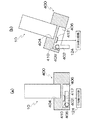
図10は、本発明に係るデジタルカメラシステムの第3の実施形態のデジタルカメラ10とクレードル400の構成を示す側面部分断面図である。
【0066】
同図に示すように、本実施の形態のデジタルカメラシステムでは、クレードル400の底に折り畳み式の足402が設けられており、この足402によってクレードル400に装着したデジタルカメラ10のアオリ角度を変えられるようにしてある。そして、この足402の折り畳みと引き出しによってUSB接続されたデジタルカメラ10のストレージモードとPCカメラモードとが切り替えられる。
【0067】
クレードル400は、上面部にデジタルカメラ10が装着される装着部404が形成されており、この装着部404の底面中央にクレードルコネクタ (不図示)が設けられている。
【0068】
一方、クレードル400の底面には凹部406が形成されており、この凹部406内に折り畳まれた足402が収容される。足402は基端部に回転軸408が設けられており、この回転軸408が凹部406内に設けられた軸受410に軸支されて揺動自在に支持されている。
【0069】
また、この凹部406内にはスイッチ412が設けられており、スイッチ412は、足402が折り畳まれると、折り畳まれた足402に押されてオフとなり、足402が引き出されると、押圧が解除されてオンとなる。このスイッチのオン/オフ信号はスイッチ検出回路124に出力される。
【0070】
スイッチ検出回路124は、このスイッチ412からのオン/オフ信号を入力することにより、クレードル400に装着されたデジタルカメラ10の保持状態を検出する。
【0071】
すなわち、図10(a)に示すように、スイッチ検出回路124は、スイッチ412からオン信号を入力することにより、足402が引き出されたことを検出し、デジタルカメラ10が傾けて設置されたことを検出する。そして、このスイッチ412からオン信号を入力することにより、スイッチ検出回路124は、クレードルコネクタとカメラコネクタを介してデジタルカメラ10のシステムコントローラ62にカメラのモードをPCカメラモードに設定する信号を出力する。デジタルカメラ10のシステムコントローラ62は、このスイッチ検出回路124からの入力信号によりデジタルカメラ10のモードをPCカメラモードに設定する。
【0072】
一方、図10(b)に示すように、スイッチ検出回路124は、スイッチ412からオフ信号を入力することにより、足402が折り畳まれたことを検出し、デジタルカメラ10が垂直に設置されたことを検出する。そして、このスイッチ412からオフ信号を入力することにより、スイッチ検出回路124は、クレードルコネクタとカメラコネクタを介してデジタルカメラ10のシステムコントローラ62にカメラのモードをストレージモードに設定する信号を出力する。デジタルカメラ10のシステムコントローラ62は、このスイッチ検出回路124からの入力信号によりデジタルカメラ10のモードをストレージモードに設定する。
【0073】
なお、クレードル400には、電源スイッチ、DCジャック、USBジャック等が設けられている点は上記第1の実施形態のクレードル100と同じである。また、デジタルカメラ10をクレードル400に装着すると、クレードル400のUSBジャックが、クレードルコネクタとカメラコネクタを介してデジタルカメラ10のUSBコントローラ72に接続され、DCジャックが、クレードルコネクタとカメラコネクタを介してデジタルカメラ10内の充電回路及びスイッチ回路74に接続される点も同じである。
【0074】
以上のように、本実施の形態のデジタルカメラシステムにおいても、クレードルに装着するデジタルカメラ10の保持状態によってストレージモードとPCカメラモードとを自動で切り替えることができる。これにより、カメラ側で設定する手間が省け、操作性が向上する。
【0075】
また、ユーザーは、クレードルに装着されたデジタルカメラ10の姿勢を見るだけで、現在の設定モードを確認することができる。
【0076】
なお、上述した実施の形態では、クレードルを介してパーソナルコンピュータに接続する例で説明したが、クレードルにA/Vジャックを設けてテレビ等と接続できるようにしてもよい。この場合、例えば、デジタルカメラ10は、アオリ角度又は装着方向により撮影モードと再生モードを切り替えられるように構成し、再生モードの場合にのみ、上面に設けられた再生送りボタン34と再生戻しボタン36が機能するように構成する。
【0077】
また、上述した実施の形態では、カメラのモードとしてPCカメラモードとストレージモードの2つのモードのみを選択できるように構成しているが、他のモードを選択できるように構成してもよい。この場合、例えば3つのモードを選択できるようにした場合は、クレードルに装着したデジタルカメラのアオリ角度を3段階に変化させるように構成する。
【0078】
また、クレードルに装着したデジタルカメラのアオリ角度と装着方向の組み合わせによって複数のモードを選択できるように構成してもよい。
【0079】
次に、本発明の第4の実施形態について説明する。
【0080】
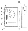
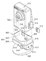
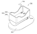
図11は第4の実施形態に係るデジタルカメラシステムの斜視図である。図11に示したシステムの内部構成については、図7で説明したブロック図と同様である。
【0081】
図11に示すように、デジタルカメラ510の一側面部にはメモリーカード512が着脱自在にセットされるカードスロット514が設けられている。カードスロット514は塵芥の侵入などを防止するために、開閉式の保護カバー516によって保護されている。
【0082】
デジタルカメラ510の底面部には、クレードル接続端子518及び電池蓋520が設けられている。なお、このクレードル接続端子518は図7で説明したカメラコネクタ38に相当するものである。図11のクレードル接続端子518は、カメラボディの外周(底面の平面部)から突出しないように凹形状に形成されている。また、端子面への塵芥侵入防止等のために開閉式の端子カバー(不図示)が設けられている。
【0083】
電池蓋520はカメラボディの底面部に対して開閉自在に取り付けられている。電池蓋520を開けると内部のバッテリ室(不図示)にアクセスできる。バッテリ室には電源用の電池522がセットされる。電池522には充電可能な二次電池が用いられる。
【0084】
クレードル600は、ベース(土台)部として機能する脚部602と、脚部602に支持されているカメラ装着部604とからなる。カメラ装着部604は、デジタルカメラ510の底部の外周形状に合わせた凹形状の箱型に形成された設置部605と、該設置部605の下部において下方に弧を描く略半円柱状に形成された下方部606とが一体に固着された構造を有している。
【0085】
設置部605の内部(凹部)の底面には接続端子608が設けられている。この接続端子608は、図7で説明したクレードルコネクタ112に相当するものである。図11の接続端子608は、設置部605にデジタルカメラ510が設置されたときにカメラ側のクレードル接続端子518に嵌合してデジタルカメラ510とクレードル600とを電気的に接続する。クレードル600はデジタルカメラ510を安定して保持する載せ置き台として機能するとともに、デジタルカメラ510と電気的に接続されることによって充電や外部機器との接続を中継するターミナルとしても機能する。
【0086】
カメラ装着部604の下方部606の一側面には、電源入力端子610及びデジタル通信端子(例えば、USB端子)612が設けられている。電源入力端子610には不図示のACパワーアダプターのプラグが接続されて電源が供給される。デジタル通信端子612には不図示の通信ケーブルを介してパーソナルコンピュータなどの外部機器が接続される。これら端子610、612はクレードル600内部で接続端子608に接続されている。なお、脚部602側に端子610、612を設ける態様も可能である。
【0087】
また、下方部606の前面には、電源ボタン614と、状態表示用の発光部616とが設けられている。電源ボタン614は、クレードル600に接続されたデジタルカメラ510の電源のオン/オフ操作に用いられる。状態表示用の発光部616は、デジタルカメラ510の動作状態に応じて発光状態(点灯/消灯/点滅、発光色など)が変化する。
【0088】
なお、設置部605においてデジタルカメラ510の下部をホールドする起立壁618のうち、カメラ背面側の一部に開口部619が形成されており、この開口部619からデジタルカメラ510のスピーカ(不図示)が露呈されるようになっている。
【0089】
図12(a),(b)は、クレードル600の正面図である。クレードル600のカメラ装着部604は、脚部602に対して図12の左右方向に移動可能に取り付けられておいる。利用者は手の力で簡単にカメラ装着部604を動かすことができる。図12(a)に示したように、カメラ装着部604を右方向にスライドさせて可動限界の位置(右寄せの端位置)で停止させると、不図示のセンサスイッチが作動してその停止位置を示す信号が出力される。この信号は接続端子608を経由してデジタルカメラ510側に伝達される。
【0090】
また、図12(b)に示したように、カメラ装着部604を左方向にスライドさせて可動限界の位置(左寄せの端位置)で停止させると、センサスイッチ(図12中不図示)が作動してその停止位置を示す信号が出力され、デジタルカメラ510側に伝達される。
【0091】
デジタルカメラ510は、クレードル600から受け取ったカメラ装着部604の位置を示す信号に従って動作モードを切り替える制御を行う。例えば、カメラ装着部604のスライド停止位置に応じてUSBモードのストレージモードとPCカメラモードとを切り替える態様、再生モードとUSBモードとを切り替える態様、再生モードと撮影モードとを切り替える態様などがある。
【0092】
USBモードの変更が行われる場合、デジタルカメラ510は、バスリセットをかけて、通信モードのコンフィグレーションをやり直し、ストレージモードからPCカメラモード(或いはその逆)へ切り替える処理を行う。
【0093】
なお、USBモードの種類は、上記したストレージモードとPCカメラモードに限定されない。例えば、デジタルカメラ510の操作系を利用してカメラ側で転送する画像を選択し、所定の手順で転送操作を行う(例えば、カメラ側の転送ボタンを押す)ことで、選択に係る画像を外部機器側に送信することができるPTP(Picture Transfer Protocol) モードを設けてもよい。
【0094】
図12では左右両端の2カ所でカメラ装着部604を停止させる例を述べたが、可動範囲内において3箇所以上の停止位置(多点ポジション)を設定することも可能である。モードの切り替えに対応付けた各停止位置で確実にカメラ装着部604を停止させることができるように、適度な力の係止機構(クリック機構など)を設けることが好ましい。
【0095】
本実施形態によれば、クレードル600にデジタルカメラ510が装着され、クレードル600を介してデジタルカメラ510とパーソナルコンピュータなどの外部機器が接続された状態において、かつデジタルカメラ510の電源がオンしている場合に、クレードル600のカメラ装着部604をデジタルカメラ510とともに、図12(a),(b)のように左右にスライドさせるだけで、デジタルカメラ510の動作モードを切り替えることができる。
【0096】
その一方、クレードル600にデジタルカメラ510が装着された状態でデジタルカメラ510の電源がオフされている場合には、自動的に充電モードに移行して、クレードル600から供給される電力によってカメラ内の電池522が充電される。
【0097】
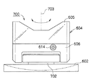
図13は本発明の第5の実施形態を示すクレードル700の正面図、図14はその斜視図である。なお、これらの図面中、図11及び図12と共通する部分には同一の符号を付し、説明は省略する。
【0098】
図13に示したクレードル700は、カメラ装着部604と脚部602との連結部分702に回転機構が設けられており、図13上でクレードル700の上下方向と並行な回転軸703を中心にしてカメラ装着部604が脚部602に対して回動自在に取り付けられている。利用者は手の力で簡単にカメラ装着部604を回動させることができる。なお、このような回転機構を有するクレードル700の場合、電源入力端子610やデジタル通信端子612は脚部602側に設ける態様が好ましい。
【0099】
本発明の実施に際して、回転機構の可動範囲は特に限定されないが、脚部602の位置を動かさずに、デジタルカメラ510の向きを180度回転できるように構成する態様が好ましい。最大可動範囲が180度の回転機構を採用すれば、脚部602を固定したまま、カメラ装着部604のみを回転軸703を中心に180度回転させるだけで、デジタルカメラ510の撮影レンズを正面に向けた状態から、カメラ背面の液晶モニタを正面に向けた状態に(又はその逆に)することが可能となる。
【0100】
例えば、図13に示したようにデジタルカメラ510を正面に向けた状態で保持する位置(これを基準位置とする。)から、カメラ装着部604を180度回転させた位置(デジタルカメラ510を後ろ向きにした状態で保持する位置)まで回動可能な構成とし、この可動範囲を規定する可動限界の端位置(すなわち、基準位置と180度位置)でカメラ装着部604を停止させると、その停止位置を示す信号が出力される。
【0101】
カメラ装着部604の停止位置に応じた信号は接続端子608を経由してデジタルカメラ510側に送られ、デジタルカメラ510のモードが自動的に切り替えられる。
【0102】
もちろん、図13に示した基準位置から左右それぞれの方向に180度の範囲で回動できる構成にしてもよいし、回転軸703を中心に360度回動できる構成も可能である。また、回転範囲に制限を設けない構成(回転範囲を規制するストッパを有していないエンドレス構造)も可能である。
【0103】
デジタルカメラ510のモードの切り替えに対応付けたカメラ装着部604の停止位置の数は2カ所に限定されず、更に多数の停止位置を設定してそれぞれの位置を示す信号を発生させ、多種類のモード変更制御を行う態様も可能である。
【0104】
図13に示した例では上述の回転機構に加えて、デジタルカメラ510のアオリ角度を変更できるように、カメラ装着部604が脚部602に対して傾動自在に取り付けられている。デジタルカメラ510のアオリ角度と回転位置とをそれぞれ検出し、これら組み合わせてデジタルカメラ510のモードを切り替える態様も可能である。
【0105】
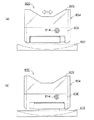
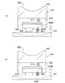
図15は、本発明の第6の実施形態を示すクレードル800の正面図である。同図中、図11及び図12と共通する部分には同一の符号を付し、説明は省略する。図15に示したクレードル800においては、カメラ装着部604が脚部602に対して図の上下方向に移動可能に取り付けられている。
【0106】
図15中の部分断面図で示したとおり、脚部602の支柱部分802に係止用の突起部804が形成されており、カメラ装着部604の支柱受け部806に前記突起部804が係合し得る凹部808A、808Bが形成されている。
【0107】
図15(a)に示したように、カメラ装着部604を脚部602から持ち上げるように引き上げると、突起部804が下側の凹部808Aに係合されて停止する。
【0108】
また、図15(a)の状態からカメラ装着部604を下方に押し下げると、その押し下げ力によって突起部804と凹部808Aとの係合が外れて、図15(B)に示すように突起部804は上側の凹部808Bと係合して停止する。
【0109】
図15(a)及び図15(b)で示した各停止位置の状態に応じた信号を生成し、これをデジタルカメラ510側に送ることによってデジタルカメラ510のモードが自動的に変更される。
【0110】
なお、上下方向に移動させる構造は図15で例示した伸縮機構に限定されず、他の機構を採用してもよい。
【0111】
また、図15では、上下の2段階方式を例示したが、3段階以上の多段階方式の構造も可能である。
【0112】
更に、本発明の実施に際しては、アオリ角度を変更する傾動機構、スライド機構、回転機構及び上下移動機構など異なる種類の移動機構を適宜組み合わせることも可能である。
【0113】
上述した各実施形態においては、デジタルカメラの姿勢、向き、或いは位置を変えるようなクレードルの構造を述べたが、このような構造は、外観上デジタルカメラの姿勢、向き、或いは位置に着目すれば、一目で現在の設定状態(モード)を把握することができるという利点がある。なお、本発明の実施に際しては、クレードルに装着されたデジタルカメラの姿勢、向き、或いは位置などを変えずに、クレードルの可動部が変位する構造も可能である。
【0114】
【発明の効果】
以上説明したように、本発明によれば、クレードルにデジタルカメラを装着した状態でクレードルの可動部を動かすと、その可動部の位置応じた指令信号が生成され、この指令信号に従ってデジタルカメラの動作モード(すなわち、機能)が切り替えられる。これにより、煩わしい設定作業が不要になり、操作性が向上する。
【0115】
また、本発明によれば、クレードルに装着したデジタルカメラのアオリ角度又は向きに応じて外部機器に対するデジタルカメラの機能が切り替えられる。これにより、煩わしい設定作業が不要になり、操作性が向上する。また、クレードルに装着されたデジタルカメラのアオリ角度により一目で現在の設定状態を確認することができる。
【図面の簡単な説明】
【図1】本発明に係るデジタルカメラシステムの第1の実施形態を示す斜視図
【図2】デジタルカメラとクレードルの外観を示す正面図
【図3】デジタルカメラとクレードルの外観を示す背面図
【図4】デジタルカメラの上面図
【図5】デジタルカメラの底面図
【図6】クレードルの側面断面図
【図7】デジタルカメラとクレードルの内部回路の概略を示すブロック図
【図8】第2の実施形態のデジタルカメラとクレードルの外観を示す正面図
【図9】第2の実施形態のデジタルカメラの底面図とクレードルの平面図
【図10】第3の実施形態のデジタルカメラとクレードルの構成を示す側面部分断面図
【図11】第4の実施形態を示すデジタルカメラシステムの斜視図
【図12】図11に示したクレードルの正面図
【図13】第5の実施形態を示すクレードルの正面図
【図14】図13に示したクレードルの斜視図
【図15】第6の実施形態を示すクレードルの正面図
【符号の説明】
10…デジタルカメラ、12…撮影レンズ、14…ストロボ、16…ファインダー窓、18…ファインダー、20…十字ボタン、22…メニュー/OKボタン、24…キャンセルボタン、26…液晶モニタ、28…シャッターボタン、30…電源ボタン、32…モードスイッチ、34…再生送りボタン、36…再生戻しボタン、38…カメラコネクタ、52…撮像部、54…信号処理部、58…絞り、60…固体撮像素子、62…システムコントローラ、64…アンプ、66…A/D変換器、68…デジタル信号処理部、70…圧縮処理部、72…USBコントローラ、74…充電回路及びスイッチ回路、76…充電電池、78…DC−DCコンバータ、80…メモリーコントローラ、82…メモリーカード、100…クレードル、102…クレードル本体、104…カメラ装着部、106…凹部、106A…前内壁面、106B…後内壁面、108…DCジャック、110…USBジャック、112…クレードルコネクタ、114…軸受部材、118…シャフト、122A…前スイッチ、122B…後スイッチ、124…スイッチ検出回路、200…パーソナルコンピュータ、210…USBケーブル、300…クレードル、302…装着部、304A、304B…穴、306A、306B…スイッチ、308…突起、400…クレードル、402…足、404…装着部、406…凹部、408…回転軸、410…軸受、412…スイッチ,510…デジタルカメラ、518…クレードル接続端子、522…電池、600…クレードル、602…脚部、604…カメラ装着部、608…接続端子、610…電源入力端子、612…デジタル通信端子、614…電源ボタン、700…クレードル、800…クレードル[0001]
BACKGROUND OF THE INVENTION
The present invention relates to a digital camera system, and more particularly to a digital camera system in which a digital camera is connected to an external device such as a personal computer via a cradle.
[0002]
[Prior art]
The digital camera can be connected to a personal computer, and thus captured image data can be taken into the personal computer.
[0003]
A cable is generally used to connect a personal computer and a digital camera. However, the connection by the cable is troublesome and takes time.
[0004]
Accordingly, a camera system for connecting a digital camera and a personal computer using a cradle has been proposed in order to make it easier to connect the personal computer and the digital camera (Japanese Patent Application No. 2001-8067). . In this system, a digital camera and a personal computer can be connected by mounting the digital camera on a cradle connected to the personal computer via a cable.
[0005]
In recent years, digital cameras have a communication mode with a personal computer, a storage mode in which the digital camera functions as a card reader and a PC camera mode in which the digital camera functions as a PC camera. The recorded image data is appropriately read out and transmitted to the personal computer. In the case of the PC camera mode, the moving image data currently being photographed is continuously transmitted to the personal computer so that a video conference or the like is possible.
[0006]
[Problems to be solved by the invention]
However, in the camera system using the conventional cradle, the communication mode with the personal computer is set on the camera side, and the digital camera must be mounted on the cradle after setting the communication mode. There was a drawback of poor operability. In addition, there is a drawback that the current communication mode setting state is not known unless the settings on the camera side are confirmed.
[0007]
The present invention has been made in view of such circumstances, and an object thereof is to provide a digital camera system with good operability.
[0008]
[Means for Solving the Problems]
In order to achieve the above object, the present invention provides a digital camera system comprising a digital camera and a cradle to which the digital camera is mounted, wherein the cradle includes a movable part and the digital part according to a position of the movable part. Signal generating means for generating a command signal for changing the function of the camera, and signal transmitting means for supplying the command signal generated by the signal generating means to the digital camera, wherein the digital camera includes a cradle A signal receiving unit that receives a command signal generated according to the position of the movable part, and a mode control unit that changes an operation mode based on the command signal supplied from the cradle. .
[0009]
According to the present invention, when the movable part of the cradle is moved, the position of the movable part is detected, and a command signal corresponding to the position of the movable part is generated. This command signal is sent to the digital camera mounted on the cradle, and the operation mode (ie, function) of the digital camera is switched according to the command signal. This eliminates the need for troublesome setting work and improves operability.
[0010]
The term “digital camera” here refers to an electronic imaging device having a function of converting an optical image of a subject into digital image data, and is classified into a product class called “camera” such as a digital still camera and a digital video camera. Of course, even devices that do not belong to this category, such as mobile phones with cameras, PDAs with cameras, mobile PCs with cameras, etc. It is included in the concept of “digital camera”.
[0011]
According to one aspect of the cradle used in the camera system of the present invention, the movable unit is a camera mounting unit to which a digital camera is mounted. In this aspect, the camera mounting part can be moved together with the digital camera while the digital camera is still mounted on the camera mounting part of the cradle.
[0012]
A cradle according to another aspect includes the camera mounting portion and a leg portion that supports the camera mounting portion, and the camera mounting portion is connected to the leg portion via a movable mechanism. Features.
[0013]
In this case, according to still another aspect, the movable mechanism moves the camera mounting portion relative to the leg portion, and the movement form includes tilting, sliding, rotation, and vertical movement. At least one of them.
[0014]
Moreover, it is preferable that the structure of the said movable mechanism can move the said movable part within a fixed movable range. The stop position of the movable part is determined according to the type of operation mode that can be changed on the digital camera side. When switching between the two types of modes, at least two stop positions are set within the movable range.
[0015]
Another aspect of the cradle according to the present invention includes a communication interface for communicatively connecting to an external device, and the digital camera communicates with the external device via the cradle by mounting the digital camera on the cradle. The connection is possible.
[0016]
In this case, the signal generating means generates a signal for switching the function of the digital camera with respect to the external device that is communicably connected via the cradle.
[0017]
According to one aspect of the digital camera used in the camera system of the present invention, when the camera is mounted on the cradle and the camera power is on, the operation mode is changed based on the command signal. To do.
[0018]
Further, when the digital camera according to another aspect is mounted on the cradle with the camera power off, a charge control means for automatically setting a charging mode in which the battery in the camera is charged by the power supplied through the cradle. It is characterized by having.
[0019]
According to another aspect of the present invention, in order to achieve the above object, in the digital camera system in which the digital camera is connected to an external device by being attached to the cradle, the cradle is connected to the attached digital camera. A tilt angle changing means for changing the tilt angle, a detecting means for detecting a change in the tilt angle of the digital camera by the tilt angle changing means, and outputting a function change signal to the digital camera based on a detection result of the detecting means A digital camera system, wherein the digital camera changes a function for the external device based on a function change signal from the command means.
[0020]
According to the present invention, the function of the digital camera with respect to the external device can be switched according to the tilt angle of the digital camera attached to the cradle. This eliminates the need for troublesome setting work and improves operability. Also, the current setting state can be confirmed at a glance by the tilt angle of the digital camera mounted on the cradle.
[0021]
According to still another aspect of the present invention, in order to achieve the above object, a digital camera system in which a digital camera is connected to an external device by being attached to a cradle so that the digital camera can communicate with the external device. A mounting unit that can be mounted from any direction, a detection unit that detects the orientation of the digital camera mounted on the mounting unit, and a function change signal that is output to the digital camera based on a detection result of the detection unit The digital camera system further includes a command unit, and the digital camera changes a function for the external device based on a function change signal from the command unit.
[0022]
According to the present invention, the function of the digital camera with respect to the external device can be switched according to the direction of the digital camera attached to the cradle. This eliminates the need for troublesome setting work and improves operability. In addition, the current setting state can be confirmed at a glance by the orientation of the digital camera mounted on the cradle.
[0023]
According to another aspect of the present invention, in order to achieve the above object, a digital camera system in which a digital camera is connected to an external device by being attached to a cradle so that the digital camera can communicate with the external device. While the digital camera has a mounting unit that can be mounted from any direction, the digital camera has a detection unit that detects a direction of mounting on the mounting unit of the cradle, and the external device is based on a detection result of the detection unit. There is provided a digital camera system characterized in that the function for the camera is changed.
[0024]
According to the present invention, the function of the digital camera with respect to the external device can be switched according to the direction of the digital camera attached to the cradle. This eliminates the need for troublesome setting work and improves operability. In addition, the current setting state can be confirmed at a glance by the orientation of the digital camera mounted on the cradle.
[0025]
DETAILED DESCRIPTION OF THE INVENTION
Hereinafter, preferred embodiments of a digital camera system according to the present invention will be described with reference to the accompanying drawings.
[0026]
FIG. 1 is a perspective view showing a first embodiment of a digital camera system according to the present invention. As shown in the figure, the digital camera system of the present embodiment includes a
[0027]
2 and 3 are a front view and a rear view, respectively, showing the external appearance of the
[0028]
As shown in FIG. 2, a photographing
[0029]
The
[0030]
On the other hand, the
[0031]
As shown in FIGS. 2, 3, and 6, the
[0032]
The
[0033]
The
[0034]
A bearing
[0035]
Here, the front
[0036]
A
[0037]
FIG. 7 is a block diagram showing an outline of internal circuits of the
[0038]
As shown in the figure, the
[0039]
The
[0040]
The
[0041]
When the
[0042]
The
[0043]
The
[0044]
By the way, as described above, when the
[0045]
That is, the
[0046]
The
[0047]
As described above, in the digital camera system of the present embodiment, the storage mode and the PC camera mode can be automatically switched by changing the tilt angle of the
[0048]
Further, the user can confirm the current setting mode only by looking at the posture of the
[0049]
Note that the method of detecting the tilt angle switching of the
[0050]
FIG. 8 is a front view showing the appearance of the
[0051]
As shown in the figure, in the digital camera system of the present embodiment, the
[0052]
The
[0053]
Further, as shown in FIGS. 8 and 9, a pair of
[0054]
On the other hand, as shown in FIGS. 8 and 9, a
[0055]
Each
[0056]
The cradle is the same as the
[0057]
According to the digital camera system of the second embodiment configured as described above, when the
[0058]
The
[0059]
On the other hand, when the
[0060]
The
[0061]
Thus, also in the digital camera system of the present embodiment, the storage mode and the PC camera mode can be automatically switched depending on the orientation of the
[0062]
The user can check the current setting mode only by looking at the direction of the
[0063]
Note that the detection mechanism of the mounting direction of the
[0064]
In this embodiment, the mounting direction of the
[0065]
FIG. 10 is a side partial sectional view showing the configuration of the
[0066]
As shown in the figure, in the digital camera system of the present embodiment, a
[0067]
The
[0068]
On the other hand, a
[0069]
Further, a
[0070]
The
[0071]
That is, as shown in FIG. 10A, the
[0072]
On the other hand, as shown in FIG. 10B, the
[0073]
The
[0074]
As described above, also in the digital camera system of the present embodiment, the storage mode and the PC camera mode can be automatically switched according to the holding state of the
[0075]
Further, the user can confirm the current setting mode only by looking at the posture of the
[0076]
In the above-described embodiment, an example in which a personal computer is connected via a cradle has been described. However, an A / V jack may be provided on the cradle so that it can be connected to a television or the like. In this case, for example, the
[0077]
In the above-described embodiment, the camera mode is configured so that only two modes of the PC camera mode and the storage mode can be selected. However, another mode may be selected. In this case, for example, when three modes can be selected, the tilt angle of the digital camera attached to the cradle is changed in three stages.
[0078]
Further, a plurality of modes may be selected depending on the combination of the tilt angle and mounting direction of the digital camera mounted on the cradle.
[0079]
Next, a fourth embodiment of the present invention will be described.
[0080]
FIG. 11 is a perspective view of a digital camera system according to the fourth embodiment. The internal configuration of the system shown in FIG. 11 is the same as the block diagram described in FIG.
[0081]
As shown in FIG. 11, a
[0082]
A
[0083]
The
[0084]
The
[0085]
A
[0086]
A
[0087]
Further, on the front surface of the
[0088]
An
[0089]
12A and 12B are front views of the
[0090]
Also, as shown in FIG. 12B, when the
[0091]
The
[0092]
When the USB mode is changed, the
[0093]
The type of USB mode is not limited to the storage mode and PC camera mode described above. For example, by selecting an image to be transferred on the camera side using the operation system of the
[0094]
Although the example in which the
[0095]
According to the present embodiment, the
[0096]
On the other hand, when the power of the
[0097]
FIG. 13 is a front view of a
[0098]
The
[0099]
In the practice of the present invention, the movable range of the rotation mechanism is not particularly limited, but an embodiment in which the direction of the
[0100]
For example, as shown in FIG. 13, from the position where the
[0101]
A signal corresponding to the stop position of the
[0102]
Of course, it is possible to have a configuration that can be rotated in the range of 180 degrees in the left and right directions from the reference position shown in FIG. 13, or a configuration that can be rotated 360 degrees around the
[0103]
The number of stop positions of the
[0104]
In the example shown in FIG. 13, in addition to the rotation mechanism described above, the
[0105]
FIG. 15 is a front view of a
[0106]
As shown in the partial cross-sectional view in FIG. 15, a locking
[0107]
As shown in FIG. 15A, when the
[0108]
Further, when the
[0109]
The mode of the
[0110]
Note that the structure to be moved in the vertical direction is not limited to the expansion / contraction mechanism illustrated in FIG. 15, and other mechanisms may be employed.
[0111]
Further, in FIG. 15, an upper and lower two-stage method is illustrated, but a multi-stage structure having three or more stages is also possible.
[0112]
Furthermore, when implementing the present invention, it is possible to appropriately combine different types of moving mechanisms such as a tilting mechanism that changes the tilt angle, a sliding mechanism, a rotating mechanism, and a vertical moving mechanism.
[0113]
In each of the embodiments described above, the cradle structure that changes the attitude, orientation, or position of the digital camera has been described. However, such a structure can be obtained by focusing on the attitude, orientation, or position of the digital camera in appearance. There is an advantage that the current setting state (mode) can be grasped at a glance. In implementing the present invention, a structure in which the movable part of the cradle is displaced without changing the posture, orientation, position, or the like of the digital camera mounted on the cradle is also possible.
[0114]
【The invention's effect】
As described above, according to the present invention, when the movable part of the cradle is moved with the digital camera mounted on the cradle, a command signal corresponding to the position of the movable part is generated, and the operation of the digital camera is performed according to this command signal. The mode (ie function) is switched. This eliminates the need for troublesome setting work and improves operability.
[0115]
Further, according to the present invention, the function of the digital camera with respect to the external device can be switched according to the tilt angle or direction of the digital camera attached to the cradle. This eliminates the need for troublesome setting work and improves operability. Also, the current setting state can be confirmed at a glance by the tilt angle of the digital camera mounted on the cradle.
[Brief description of the drawings]
FIG. 1 is a perspective view showing a first embodiment of a digital camera system according to the present invention.
FIG. 2 is a front view showing the appearance of a digital camera and a cradle.
FIG. 3 is a rear view showing the appearance of a digital camera and a cradle.
FIG. 4 is a top view of a digital camera.
FIG. 5 is a bottom view of the digital camera.
FIG. 6 is a side sectional view of the cradle.
FIG. 7 is a block diagram showing an outline of an internal circuit of a digital camera and a cradle.
FIG. 8 is a front view showing the external appearance of a digital camera and a cradle according to the second embodiment.
FIG. 9 is a bottom view of a digital camera according to a second embodiment and a plan view of a cradle.
FIG. 10 is a partial cross-sectional side view illustrating a configuration of a digital camera and a cradle according to a third embodiment.
FIG. 11 is a perspective view of a digital camera system showing a fourth embodiment.
12 is a front view of the cradle shown in FIG.
FIG. 13 is a front view of a cradle showing a fifth embodiment.
14 is a perspective view of the cradle shown in FIG.
FIG. 15 is a front view of a cradle showing a sixth embodiment.
[Explanation of symbols]
DESCRIPTION OF
Claims (14)
前記クレードルは、可動部と、
前記可動部の位置に応じて前記デジタルカメラの機能を変更する指令信号を生成する信号生成手段と、
前記信号生成手段で生成された前記指令信号を前記デジタルカメラに供給する信号伝達手段と、を備え、
前記デジタルカメラは、前記クレードルの可動部の位置に応じて生成される指令信号を受け入れる信号受入手段と、
前記クレードルから供給された前記指令信号に基づいて動作モードを変更するモード制御手段と、を備えていることを特徴とするデジタルカメラシステム。In a digital camera system comprising a digital camera and a cradle on which the digital camera is mounted,
The cradle includes a movable part,
Signal generating means for generating a command signal for changing the function of the digital camera in accordance with the position of the movable part;
Signal transmitting means for supplying the command signal generated by the signal generating means to the digital camera,
The digital camera has a signal receiving means for receiving a command signal generated according to the position of the movable part of the cradle;
A digital camera system comprising: mode control means for changing an operation mode based on the command signal supplied from the cradle.
該クレードルは、可動部と、
前記可動部の位置に応じて前記デジタルカメラの機能を変更する指令信号を生成する信号生成手段と、
前記信号生成手段で生成された前記指令信号を前記デジタルカメラに供給する信号伝達手段と、
を備えたことを特徴とするクレードル。A cradle to which a digital camera is attached,
The cradle includes a movable part,
Signal generating means for generating a command signal for changing the function of the digital camera in accordance with the position of the movable part;
Signal transmitting means for supplying the command signal generated by the signal generating means to the digital camera;
A cradle characterized by comprising:
該デジタルカメラは、前記クレードルの可動部の位置に応じて生成される指令信号を受け入れる信号受入手段と、
前記信号受入手段を介して取得した前記指令信号に基づいて動作モードを変更するモード制御手段と、
を備えていることを特徴とするデジタルカメラ。A digital camera that can be attached to a cradle,
The digital camera has a signal receiving means for receiving a command signal generated according to the position of the movable part of the cradle;
Mode control means for changing an operation mode based on the command signal acquired via the signal receiving means;
A digital camera characterized by comprising:
前記クレードルは、装着されたデジタルカメラのアオリ角度を変更するアオリ角度変更手段と、前記アオリ角度変更手段による前記デジタルカメラのアオリ角度の変更を検出する検出手段と、前記検出手段の検出結果に基づいて前記デジタルカメラに機能変更信号を出力する指令手段とを備え、前記デジタルカメラは、前記指令手段からの機能変更信号に基づいて前記外部機器に対する機能を変更することを特徴とするデジタルカメラシステム。In a digital camera system in which a digital camera is connected to an external device by being attached to a cradle,
The cradle is based on a tilt angle changing means for changing the tilt angle of the mounted digital camera, a detecting means for detecting a change in the tilt angle of the digital camera by the tilt angle changing means, and a detection result of the detecting means. Command means for outputting a function change signal to the digital camera, and the digital camera changes a function for the external device based on a function change signal from the command means.
前記クレードルは、前記デジタルカメラを表裏いずれの方向からも装着可能な装着部と、前記装着部に装着された前記デジタルカメラの向きを検出する検出手段と、前記検出手段の検出結果に基づいて前記デジタルカメラに機能変更信号を出力する指令手段とを備え、前記デジタルカメラは、前記指令手段からの機能変更信号に基づいて前記外部機器に対する機能を変更することを特徴とするデジタルカメラシステム。In a digital camera system in which a digital camera is connected to an external device by being attached to a cradle,
The cradle includes a mounting unit that can mount the digital camera from either front or back, a detecting unit that detects a direction of the digital camera mounted on the mounting unit, and a detection result of the detecting unit based on the detection result. Command means for outputting a function change signal to the digital camera, wherein the digital camera changes a function for the external device based on a function change signal from the command means.
前記クレードルは、前記デジタルカメラを表裏いずれの方向からも装着可能な装着部を有する一方、前記デジタルカメラは、前記クレードルの装着部に装着された向きを検出する検出手段を有し、該検出手段の検出結果に基づいて前記外部機器に対する機能が変更されることを特徴とするデジタルカメラシステム。In a digital camera system in which a digital camera is connected to an external device by being attached to a cradle,
The cradle has a mounting portion that allows the digital camera to be mounted from either the front or back direction, while the digital camera has a detection unit that detects a direction in which the digital camera is mounted on the mounting unit. A digital camera system, wherein a function for the external device is changed based on a detection result of the above.
Priority Applications (4)
| Application Number | Priority Date | Filing Date | Title |
|---|---|---|---|
| JP2003104965A JP2004088729A (en) | 2002-06-25 | 2003-04-09 | Digital camera system |
| KR1020030028118A KR100570163B1 (en) | 2002-06-25 | 2003-05-02 | Digital camera system |
| US10/601,530 US7538792B2 (en) | 2002-06-25 | 2003-06-24 | Digital camera and cradle on which the digital camera is mounted |
| CNB031477186A CN1225894C (en) | 2002-06-25 | 2003-06-24 | Digital camera system |
Applications Claiming Priority (2)
| Application Number | Priority Date | Filing Date | Title |
|---|---|---|---|
| JP2002183789 | 2002-06-25 | ||
| JP2003104965A JP2004088729A (en) | 2002-06-25 | 2003-04-09 | Digital camera system |
Publications (1)
| Publication Number | Publication Date |
|---|---|
| JP2004088729A true JP2004088729A (en) | 2004-03-18 |
Family
ID=30002268
Family Applications (1)
| Application Number | Title | Priority Date | Filing Date |
|---|---|---|---|
| JP2003104965A Pending JP2004088729A (en) | 2002-06-25 | 2003-04-09 | Digital camera system |
Country Status (4)
| Country | Link |
|---|---|
| US (1) | US7538792B2 (en) |
| JP (1) | JP2004088729A (en) |
| KR (1) | KR100570163B1 (en) |
| CN (1) | CN1225894C (en) |
Cited By (4)
| Publication number | Priority date | Publication date | Assignee | Title |
|---|---|---|---|---|
| JP2006157349A (en) * | 2004-11-29 | 2006-06-15 | Nikon Corp | Auxiliary device for electronic equipment with projector and electronic camera system |
| JP2008526143A (en) * | 2004-12-31 | 2008-07-17 | 聯想(北京)有限公司 | Method of acquiring video data using a camera-equipped mobile phone as a computer camera |
| JP2009290877A (en) * | 2009-07-10 | 2009-12-10 | Casio Comput Co Ltd | Imaging system, and mobile electronic apparatus |
| JP2019101936A (en) * | 2017-12-06 | 2019-06-24 | キヤノン株式会社 | Electronic device and method for controlling the same |
Families Citing this family (47)
| Publication number | Priority date | Publication date | Assignee | Title |
|---|---|---|---|---|
| JP2002359761A (en) * | 2001-05-31 | 2002-12-13 | Asahi Optical Co Ltd | Cradle for digital camera |
| US7253840B2 (en) * | 2001-06-11 | 2007-08-07 | Fujifilm Corporation | Cradle for digital camera |
| US6812971B2 (en) * | 2001-09-11 | 2004-11-02 | Olympus Optical Co., Ltd. | Electronic apparatus, stand and electronic apparatus stand system |
| US7265790B2 (en) * | 2003-07-07 | 2007-09-04 | Hewlett-Packard Development Company, L.P. | System and method for setting an image capture device to an operational mode |
| JP4502360B2 (en) * | 2003-08-27 | 2010-07-14 | キヤノン株式会社 | Imaging device |
| US20050088572A1 (en) * | 2003-10-28 | 2005-04-28 | Pandit Amol S. | System and method for a camera docking station |
| US7551225B2 (en) * | 2003-12-09 | 2009-06-23 | Sony Ericsson Mobile Communications Ab | Positioning accessory for camera-equipped wireless terminals |
| US7479759B2 (en) * | 2004-02-26 | 2009-01-20 | Research In Motion Limited | Electronic device including handheld electronic device with dual battery configuration, and associated method |
| EP1600886A1 (en) * | 2004-05-18 | 2005-11-30 | Aiptek International Inc. | Information processing device with expansible function module |
| JP4457805B2 (en) * | 2004-08-13 | 2010-04-28 | 株式会社ニコン | Electronic device system and electronic camera system |
| US20060118624A1 (en) * | 2004-12-06 | 2006-06-08 | International Business Machines Corporation | Systems and methods for preventing use of card skimmers on electronic card terminals |
| JP4396511B2 (en) * | 2004-12-20 | 2010-01-13 | ソニー株式会社 | Printing system |
| KR100750117B1 (en) * | 2005-01-19 | 2007-08-21 | 삼성전자주식회사 | Method and device for setting class of USB device |
| JP4759322B2 (en) * | 2005-06-08 | 2011-08-31 | キヤノン株式会社 | Cradle device, imaging system control method, and computer program |
| KR100704631B1 (en) * | 2005-08-10 | 2007-04-10 | 삼성전자주식회사 | Voice annotation generating device and method |
| JP4953603B2 (en) * | 2005-09-09 | 2012-06-13 | キヤノン株式会社 | Imaging apparatus and control method thereof |
| US20070132259A1 (en) * | 2005-12-09 | 2007-06-14 | Arkady Ivannikov | Transport frame and optional fixture for battery-powered electronic devices |
| US7684090B2 (en) * | 2005-12-20 | 2010-03-23 | Eastman Kodak Company | Digital printer for use with docked display device |
| US8035368B2 (en) * | 2006-02-13 | 2011-10-11 | Freescale Semiconductor, Inc. | Integrated circuit, universal serial bus on-the-go power source and methods for use therewith |
| JP2007300387A (en) * | 2006-04-28 | 2007-11-15 | Eastman Kodak Co | Base mount for digital camera |
| JP2008083149A (en) * | 2006-09-26 | 2008-04-10 | Olympus Corp | Imaging apparatus with removable optical unit |
| KR101229496B1 (en) * | 2006-11-29 | 2013-02-04 | 삼성전자주식회사 | A camera movement controller and the method thereof |
| US20090024769A1 (en) * | 2007-05-08 | 2009-01-22 | Atsuhito Nakatani | Operating device for electronic equipment, operating system, image processing apparatus, information display apparatus, and external equipment connecting device |
| US8009228B2 (en) * | 2007-07-12 | 2011-08-30 | Ricoh Company, Ltd. | Camera and direction indicating switch |
| US20090090864A1 (en) * | 2007-10-03 | 2009-04-09 | Tracy Glatzmaier | Thermal imager having integrated support assembly |
| JP4636132B2 (en) | 2008-07-09 | 2011-02-23 | ソニー株式会社 | Network camera |
| US8323040B2 (en) * | 2008-09-05 | 2012-12-04 | Apple Inc. | Docking station with moveable connector for hand-held electronic device |
| JP4983784B2 (en) * | 2008-12-18 | 2012-07-25 | ソニー株式会社 | Imaging system, image presentation method, control device, program |
| US9131135B2 (en) * | 2009-06-09 | 2015-09-08 | Apple Inc. | Electronic device flash shutter |
| KR101701922B1 (en) | 2009-11-17 | 2017-02-02 | 삼성전자 주식회사 | Docking apparatus for portable device |
| US8223483B2 (en) | 2010-01-04 | 2012-07-17 | Apple Inc. | Dock with moveable connector for display device |
| US20120281102A1 (en) * | 2010-02-01 | 2012-11-08 | Nec Corporation | Portable terminal, activity history depiction method, and activity history depiction system |
| JP5790248B2 (en) * | 2011-07-27 | 2015-10-07 | 株式会社リコー | Image projection device |
| US9160124B2 (en) * | 2012-09-07 | 2015-10-13 | Apple Inc. | Compliant mount for connector |
| US8721356B2 (en) | 2012-09-11 | 2014-05-13 | Apple Inc. | Dock with compliant connector mount |
| US8986029B2 (en) | 2012-09-11 | 2015-03-24 | Apple Inc. | Dock connector with compliance mechanism |
| US20140085491A1 (en) * | 2012-09-27 | 2014-03-27 | JVC Kenwood Corporation | Imaging device and cradle |
| US9201453B2 (en) | 2012-10-26 | 2015-12-01 | Apple Inc. | Self-retracting connector for docking device |
| USD730354S1 (en) * | 2013-02-13 | 2015-05-26 | Isaac S. Daniel | Electronic card reader device with camera and displaying means |
| WO2014125743A1 (en) * | 2013-02-18 | 2014-08-21 | 株式会社ソニー・コンピュータエンタテインメント | Camera and camera assembly |
| US9454183B2 (en) * | 2013-08-02 | 2016-09-27 | Belkin International, Inc. | Adjustable docking stand and method of providing and using the same |
| US9836086B2 (en) | 2013-08-02 | 2017-12-05 | Belkin International, Inc. | Adjustable docking stand with ejector and method of providing and using the same |
| US9774767B2 (en) * | 2015-11-29 | 2017-09-26 | Jianhua Cao | Digital memory card window arrangement for IP camera |
| CN105578004A (en) * | 2015-12-18 | 2016-05-11 | 苏州翠南电子科技有限公司 | Digital camera |
| CN108111602B (en) * | 2017-12-20 | 2021-06-11 | 深圳Tcl新技术有限公司 | Data pushing method and device and computer readable storage medium |
| JP6511178B1 (en) | 2018-03-02 | 2019-05-15 | 任天堂株式会社 | Power-on device |
| US11388324B2 (en) * | 2020-06-15 | 2022-07-12 | Intel Corporation | Camera device, base unit, computation device, and corresponding methods and computer programs |
Family Cites Families (15)
| Publication number | Priority date | Publication date | Assignee | Title |
|---|---|---|---|---|
| US5396269A (en) * | 1991-02-20 | 1995-03-07 | Hitachi, Ltd. | Television telephone |
| US5374971A (en) * | 1993-03-12 | 1994-12-20 | Picturetel Corporation | Two-view video camera stand and support method |
| US5452180A (en) * | 1993-07-15 | 1995-09-19 | Dell Usa, L.P. | Docking apparatus for a portable data processing unit including an arcuate support member with a card extension pivotally mounted on a base member |
| US5734414A (en) * | 1994-03-03 | 1998-03-31 | Matsushita Electric Industrial Co., Ltd. | Camera apparatus for electronic conference |
| JPH07327162A (en) * | 1994-06-02 | 1995-12-12 | Nec Corp | Image input device |
| US6081422A (en) * | 1997-08-19 | 2000-06-27 | Compaq Computer Corporation | Universal mount for computer peripheral device |
| US7016595B1 (en) * | 1999-05-28 | 2006-03-21 | Nikon Corporation | Television set capable of controlling external device and image storage controlled by television set |
| JP4434501B2 (en) | 2001-01-16 | 2010-03-17 | 富士フイルム株式会社 | Digital camera, cradle and camera system |
| US20040201774A1 (en) * | 2001-05-15 | 2004-10-14 | Gennetten K. Douglas | Docked camera becomes electronic picture frame |
| JP2002354306A (en) * | 2001-05-22 | 2002-12-06 | Sony Computer Entertainment Inc | Imaging device |
| JP4192441B2 (en) * | 2001-05-28 | 2008-12-10 | 富士フイルム株式会社 | Camera cradle equipment |
| US6812971B2 (en) * | 2001-09-11 | 2004-11-02 | Olympus Optical Co., Ltd. | Electronic apparatus, stand and electronic apparatus stand system |
| US6572282B1 (en) * | 2001-12-18 | 2003-06-03 | Intel Corporation | Digital camera stand with indexed tilt feature |
| JP3535495B2 (en) * | 2001-12-26 | 2004-06-07 | 株式会社東芝 | Cradle-mounted digital camera, control method thereof, and cradle-mounted digital camera system |
| US7259793B2 (en) * | 2002-03-26 | 2007-08-21 | Eastman Kodak Company | Display module for supporting a digital image display device |
-
2003
- 2003-04-09 JP JP2003104965A patent/JP2004088729A/en active Pending
- 2003-05-02 KR KR1020030028118A patent/KR100570163B1/en not_active Expired - Fee Related
- 2003-06-24 US US10/601,530 patent/US7538792B2/en not_active Expired - Fee Related
- 2003-06-24 CN CNB031477186A patent/CN1225894C/en not_active Expired - Fee Related
Cited By (5)
| Publication number | Priority date | Publication date | Assignee | Title |
|---|---|---|---|---|
| JP2006157349A (en) * | 2004-11-29 | 2006-06-15 | Nikon Corp | Auxiliary device for electronic equipment with projector and electronic camera system |
| JP2008526143A (en) * | 2004-12-31 | 2008-07-17 | 聯想(北京)有限公司 | Method of acquiring video data using a camera-equipped mobile phone as a computer camera |
| JP2009290877A (en) * | 2009-07-10 | 2009-12-10 | Casio Comput Co Ltd | Imaging system, and mobile electronic apparatus |
| JP2019101936A (en) * | 2017-12-06 | 2019-06-24 | キヤノン株式会社 | Electronic device and method for controlling the same |
| JP7076994B2 (en) | 2017-12-06 | 2022-05-30 | キヤノン株式会社 | Electronic devices and their control methods |
Also Published As
| Publication number | Publication date |
|---|---|
| KR20040002509A (en) | 2004-01-07 |
| KR100570163B1 (en) | 2006-04-12 |
| US7538792B2 (en) | 2009-05-26 |
| US20040004671A1 (en) | 2004-01-08 |
| CN1225894C (en) | 2005-11-02 |
| CN1469637A (en) | 2004-01-21 |
Similar Documents
| Publication | Publication Date | Title |
|---|---|---|
| JP2004088729A (en) | Digital camera system | |
| US7626630B2 (en) | Portable information terminal equipped with camera | |
| JP3987788B2 (en) | Digital camera system | |
| US7632023B2 (en) | Camera | |
| EP1524836B1 (en) | Document camera and document camera system | |
| US20020186317A1 (en) | Cradle for digital camera | |
| JP4371016B2 (en) | Electronics | |
| JP2025105942A (en) | Image capture device and control method thereof | |
| US20060215052A1 (en) | Image recording and reproducing device and key assignment changing method | |
| JP4367061B2 (en) | Imaging system and portable electronic device | |
| JP2005345576A (en) | Imaging device | |
| JP2004120290A (en) | Mobile terminal and image display method of mobile terminal | |
| JP2003315891A (en) | camera | |
| JP3987951B2 (en) | Electronic camera system | |
| JP2004201101A (en) | Digital camera | |
| JP2004179858A (en) | Digital camera system | |
| JP4564865B2 (en) | Imaging apparatus and method, and program | |
| JP2005229538A (en) | Digital camera system | |
| JP4131364B2 (en) | Cradle for digital camera | |
| JP2001186383A (en) | Personal digital assistant with camera | |
| JP2007173977A (en) | Camera | |
| JP6611601B2 (en) | Imaging device | |
| JP2005025000A (en) | Display device, display device unit | |
| JP2005252854A (en) | Cradle | |
| JP2009290877A (en) | Imaging system, and mobile electronic apparatus |