JP4564865B2 - Imaging apparatus and method, and program - Google Patents
Imaging apparatus and method, and program Download PDFInfo
- Publication number
- JP4564865B2 JP4564865B2 JP2005049111A JP2005049111A JP4564865B2 JP 4564865 B2 JP4564865 B2 JP 4564865B2 JP 2005049111 A JP2005049111 A JP 2005049111A JP 2005049111 A JP2005049111 A JP 2005049111A JP 4564865 B2 JP4564865 B2 JP 4564865B2
- Authority
- JP
- Japan
- Prior art keywords
- recording medium
- video
- external
- external recording
- trigger button
- Prior art date
- Legal status (The legal status is an assumption and is not a legal conclusion. Google has not performed a legal analysis and makes no representation as to the accuracy of the status listed.)
- Expired - Fee Related
Links
Images


Description
本発明は、テープなどの記録媒体を使用するビデオカメラ等のカメラ装置に関するものである。 The present invention relates to a camera device such as a video camera that uses a recording medium such as a tape.
これまで動画を記録する手段として、テープを記録媒体とする様々なビデオカメラが開発され、広く一般に普及している。近年では、DVフォーマットのように動画をデジタル信号処理して記録するDVCが主流となっている。これらの中にはメモリーカードスロットを備え、静止画や高圧縮率のMPEG4動画データなどをメモリーカードに記録できるようにした製品も多くなっている。 Various video cameras using a tape as a recording medium have been developed and widely spread as a means for recording moving images. In recent years, DVC, which records a moving image by digital signal processing like the DV format, has become mainstream. Many of these products are equipped with a memory card slot and can record still images and high-compression MPEG4 video data on memory cards.
また、これらのビデオカメラは、撮影対象や再生映像を確認するための手段としてビューファインダーのほかに、比較的大型の液晶パネルを備えるのが一般的である。そこで、動画や静止画を記録・再生する以外にビデオカメラの用途を広げるものとして、TVチューナーパックを用意し、ビデオカメラ専用の取り付け部もしくはドッキングステーション上でビデオカメラとTVチューナーパックを接続することで、上記液晶パネルでTV鑑賞ができるように構成した製品が提案されている(特許文献1等)。
Further, these video cameras generally include a relatively large liquid crystal panel in addition to a viewfinder as a means for confirming a subject to be photographed and a reproduced video. Therefore, in order to expand the use of the video camera in addition to recording and playing back movies and still images, prepare a TV tuner pack, and connect the video camera and the TV tuner pack on the video camera dedicated mounting section or docking station. Thus, products configured to allow TV viewing on the liquid crystal panel have been proposed (
図13はその一例を示すもので、図において41はチューナーユニット、42はビデオカメラ(デッキ部)本体である。チューナーユニット41は、ビデオカメラ本体42の側面に設けられた結合部43にチューナーユニットを接続し、固定することで本体へTV映像信号を送るように構成されている。チューナーユニット41には、電源スイッチ44、選局ボタン45、音量ボタン46などが備えられている。
FIG. 13 shows an example thereof. In the figure, 41 is a tuner unit, and 42 is a video camera (deck unit) main body. The
しかしながら、従来のチューナーパックは大きく、ビデオカメラ本体とともに携帯するのに不便であった。また、ビデオカメラ本体に取り付ける手間がかかる上、チューナーパック自体に電源スイッチや選局ボタンが設けられており、ビデオカメラ本体と接合したときの操作性に劣るほか、小型化にも不利であった。 However, the conventional tuner pack is large and inconvenient to carry with the video camera body. In addition, it takes time and effort to attach to the video camera body, and the tuner pack itself is provided with a power switch and a channel selection button. .
そこで、本発明は使用性、操作性等に優れ、小型化を有効に実現するカメラ装置を提供することを目的とする。 Therefore, an object of the present invention is to provide a camera device that is excellent in usability, operability, and the like and that effectively realizes downsizing.
本発明の撮影装置は、トリガボタンへの操作に応じて被写体の映像を撮影する撮影手段と、前記撮影手段によって撮影された映像を記録可能な第1の外部記録媒体と、前記第1の外部記録媒体とは異なる外部機器とに接続可能な第1の接続手段と、前記第1の外部記録媒体とは異なる第2の外部記録媒体を接続可能な第2の接続手段と、映像を、前記第1の接続手段に接続されている前記第1の外部記録媒体に記録するか、前記第2の接続手段に接続されている前記第2の外部記録媒体に記録するかを選択する選択手段と、前記第1の外部記録媒体に映像を記録すると選択された場合に、前記接続手段に前記第1の外部記録媒体が接続されているか、または、TVチューナーの機能を有する外部機器が接続されているかを判別する判別手段と、前記判別手段により前記第1の外部記録媒体が接続されていると判別された場合は、撮影モードに、前記判別手段により前記TVチューナーの機能を有する外部機器が接続されていると判別された場合はTV視聴モードに、自動的に切り替えるモード切替手段と、前記トリガボタンの押下に応じて映像の記録を開始し、映像の記録中に再度前記トリガボタンが押下されたことに応じて、映像の記録を停止し、映像の記録を制御する制御手段であって、前記撮影モードの場合は、前記トリガボタンの押下に応じて、前記撮影手段により撮影した映像を前記第1の外部記録媒体に記録し、前記TV視聴モードの場合には、前記トリガボタンの押下に応じて、TV映像を前記第2の外部記録媒体に記録する制御手段とを有し、前記制御手段は、前記第1の接続手段に接続されている前記第1の外部記録媒体に映像を記録すると選択されていても、前記TV視聴モードの場合には、前記第2の外部記録媒体に映像を記録することを特徴とする。 Imaging apparatus of the present invention includes a photographing unit for photographing an image of a subject in response to the operation of the trigger button, a first external recording medium capable of recording images captured by the imaging means, the first external A first connection means connectable to an external device different from the recording medium; a second connection means connectable to a second external recording medium different from the first external recording medium; Selecting means for selecting whether to record on the first external recording medium connected to the first connecting means or to record on the second external recording medium connected to the second connecting means; When the video recording is selected to be recorded on the first external recording medium, the first external recording medium is connected to the connection means or an external device having a TV tuner function is connected. and determining means for determining a dolphin If and when the first external storage medium is judged to be connected by said determination means, the photographing mode, an external device having the function of the TV tuner is judged to be connected by said discrimination means Is a mode switching means for automatically switching to the TV viewing mode, and starts video recording in response to pressing of the trigger button, and in response to the trigger button being pressed again during video recording, Control means for stopping recording and controlling video recording. In the case of the shooting mode, the video shot by the shooting means is recorded on the first external recording medium in response to pressing of the trigger button. In the case of the TV viewing mode, control means for recording a TV video on the second external recording medium in response to pressing of the trigger button, the control means It is selected and records the video in the first external storage medium connected to the first connecting means, in the case of the TV viewing mode, to record an image on the second external storage medium It is characterized by.
本発明によれば、TV視聴が可能なカメラにおいて、カメラ本体の操作部を適宜TV視聴用の操作部として割り当てることによって、カメラの操作部を増やすことなくカメラにおける快適なTV視聴を可能にする。 According to the present invention, in a camera capable of TV viewing, by assigning the operating portion of the camera body as the operation unit of the appropriate TV for viewing, allowing a comfortable TV viewing in the camera without increasing the operation of the camera .
以下、図面に基づき本発明によるカメラ装置の好適な実施の形態を説明する。
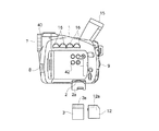
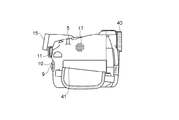
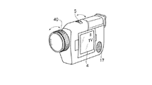
図1〜図4は、本発明を適用したビデオカメラの各側面を示した図である。1はビデオカメラ本体、2は開閉自在な蓋2aを備えたメモリーカードスロット、3はメモリーカードスロット2に挿入可能なTVチューナーカード、4は液晶表示パネル、5はズームレバーもしくはボタン 、6はメニューボタン、7はレンズ、8はマイク、9はトリガーボタン、10は電源切り替えスイッチ、11はテープ・カード切り替えボタン、12はメモリーカード、15はビューファインダー、16はレコーダー操作ボタン、17はスピーカー、40はフォーカスリングである。
Preferred embodiments of a camera device according to the present invention will be described below with reference to the drawings.
1 to 4 are views showing each side of a video camera to which the present invention is applied. 1 is a video camera body, 2 is a memory card slot with an openable /
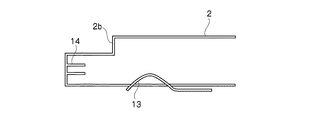
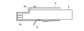
図5は、メモリーカードスロットの内部構造を示す図である。13はメモリーカード12と接続する端子列、14はTVチューナーカード3用の端子列である。TVチューナーカードについては特開平6−178218号公報等に開示されているように、先端に信号の入出力を行うコネクタ3aが設けられており、その外形はメモリーカードの大きさと略同一であるが、外形にメモリーカードとは異なる形状(3b)が形成される。この部分に対し、メモリーカードスロット2の段部2bがストッパーとなって、メモリーカード2とは異なる挿入深さとなるように構成されている。
FIG. 5 shows the internal structure of the memory card slot.
メモリーカード12にも同様に信号の入出力用の端子12aが設けられているが、TVチューナーカード3の端子列とは配列・数ともに異なる。このため本発明のビデオカメラに搭載されるメモリースロット2には、それぞれのカードに適合する端子列が設けられている。
Similarly, the
メモリーカードスロット2にメモリーカード12が挿入された場合には、第7図に示すように、メモリーカード用の端子列13がメモリーカード12の端子部12aと接触し、TVチューナーカード3が挿入された場合には、第6図に示すように、TVチューナーカード3の本体が前記メモリーカード用の端子列12aを押しのけるようになっており、その奥に位置するTVチューナーカード用の端子列14とTVチューナーカード3のコネクタ3aが接触するように構成されている。
When the
上記構成は、TVチューナーカード3がアナログチューナーである場合であるが、TVチューナーカード3がデジタルチューナーカードである場合には、TVチューナーカード内で信号を処理することによって、メモリーカードと同様の端子列で信号を授受することも可能である。この場合、メモリーカードスロットの端子列は、メモリーカード用の端子列13のみ備えればよい。
The above configuration is a case where the
図8は、本発明によるビデオカメラの概略構成を示すブロック図である。図においてCPU23は、ROM24に格納された本発明によるビデオカメラの制御プログラムを実行し、RAM25をワークエリアとして使用する。キーボタン34は、図1から図4に示したズームボタン5、フォーカスリング40、トリガーボタン9等の各種操作ボタンを示すものである。CPU23はキーボタン34及び、電源切り替えスイッチ10、テープ・カード切り替えSW11から得られるユーザ入力情報に従って、装置内の各部を制御する。
FIG. 8 is a block diagram showing a schematic configuration of a video camera according to the present invention. In the figure, a
例えばズームボタン5は中立位置からテレ側、ワイド側へと操作できりようにボタンが構成される。それぞれの側にボタンを動かしたときに、図示しない内部SWがONとなり、CPU23は、このSWのON/OFF状態によりレンズ7のズームモータ−を駆動し、レンズのズーミング動作を行うよう制御する。
For example, the
同様に、フォーカスリング40の回転動作を図示しないパルス検出手段により検出し、CPU23はレンズ7のフォーカスモーターを駆動させ、ピント合わせを行う。電源Sw10がカメラモードの場合、レンズ7を介して被写体の映像がCCD28の受光面に結像し、CCD28は映像信号を出力する。CCD信号処理部29はCCD28からの映像信号を処理し、デジタルの映像データを出力する。これらレンズ7、CCD28、CCD信号処理部29がまとまってカメラ部を構成する。
Similarly, the rotation operation of the
また、マイク8により収録された音声はアンプ21により増幅され、A/D変換器22によりA/D変換される。前記カメラ部からのデジタル映像データと、デジタル音声データを圧縮伸張部19が圧縮処理して、テープもしくはカードに映像を記録する。この選択は、テープ・カード切り替えボタン11でなされ、カード記録時には、映像データは圧縮・伸長部19により例えばMPEG4で圧縮され、カードI/F36を介してメモリーカード37に記録される。また、テープ記録時には、映像データは例えばDVフォーマットに基づいて圧縮され、VTR I/F33を介してテープ媒体に映像信号を記録する。
The sound recorded by the
カメラ撮影時には、ズームボタン5、フォーカスリング40が最も頻繁に使用される操作キーである。これらのキーは使用頻度も高いことから、特に操作性を考慮した形状となっている。
During camera shooting, the
カードI/F36は、メモリーカードスロット37に装填されたカードが、メモリーカードなのかチューナーカードなのかを判別する。そして、その情報をCPU23に送る。CPU23はその情報に基づき、カメラ部のON/OFFや、操作ボタンの切り替え等を行う。
The card I /
図9は、本発明によるビデオカメラの動作を示したものである。前述したようにメモリーカードを備えるビデオカメラにおいては、テープへの記録再生と、カードへの記録再生とにおいて、その圧縮フォーマットや画像解像度が異なる。このためテープ・カード切り替えボタン11によって映像信号処理方法を切り替えるように構成されている。
FIG. 9 shows the operation of the video camera according to the present invention. As described above, in a video camera equipped with a memory card, the compression format and image resolution differ between recording and reproduction on a tape and recording and reproduction on a card. Therefore, the video signal processing method is switched by the tape /
テープ・カード切り替えボタン11が“テープ”モードの時には、電源切り替えスイッチ10を“カメラ”モードにすることによって、カメラ部の電源がオンする。液晶パネル4には、カメラ部の映像出力(撮影対象)が表示され、テープデッキ部41が記録スタンバイ状態になる。トリガーボタン9を一回押すと、テープ走行がスタートし、カメラ部映像信号のテープ記録が開始される。もう一度トリガーボタン9を押すとテープ記録が停止し、再度記録スタンバイ状態となるように構成される。
When the tape /
カメラ部の電源がオンの状態では、カメラ系の操作ボタンが有効であり、ズームボタンや、シャッタースピード、プログラムAE等の露出制御ボタンを使用して、好みに合わせて撮影画像を調整して記録することができる。 When the camera unit is turned on, the camera operation buttons are enabled, and the zoom button, exposure control buttons such as shutter speed, program AE, etc. are used to adjust the recorded image to your liking and record it. can do.
また、“テープ”モードで電源切り替えスイッチ10を“VTR”モードにすると、カメラ部の電源がオフとなる。この場合、テープデッキ部分の再生機能が使用できるようになり、再生・早送り・巻き戻し・スロー再生等のボタンを操作してテープ記録信号の再生ができる。このとき再生映像は液晶パネル4に表示される。
When the
次に、テープ・カード切り替えボタン11を“カード”モードにした場合、カードI/F33は、そのカードがメモリーカードなのかチューナーカードなのかを判別する。カードがメモリーカードである場合、メモリーカード用の信号処理を行い、上記の“テープ”モードと同様に、電源切り替えスイッチ10を選択することによって、メモリーカードに画像を記録・再生することができる。すなわち、記録再生媒体がテープからメモリーカードに変わっただけで、両者の基本的な動作は同じものである。(図中破線の範囲)
Next, when the tape /
また、カードがチューナーカードである場合には、電源切り替えスイッチ10の位置に関わらず、カメラ部の電源はOFFとなり強制的にVTRモードとなる。このとき液晶パネル4には、チューナーカードが装填されていることと、強制的にVTRモードになっていることが分かり易く表示され、使用者が戸惑わないように構成されている。この場合、液晶パネル4にはTVのCH(チャンネル)表示がされるが、これは表示のON/OFFで消すこともできる。
When the card is a tuner card, the camera unit is turned off regardless of the position of the
また、CHの切り替えは、ズームボタン5によって操作することができるように割り当てられる。チューナーカードを使用するときには、カメラ部は使用されることが無いため、操作性に優れ、直感的にもCH切り替え操作ボタンと認識し易いズームボタン5をCH切り替えに割り当てることで、操作性に優れたTV視聴が可能となる。
Also, the switching of CH is assigned so that it can be operated by the
ところで、ズームボタン5は常に中立位置へと復帰するように構成され、ズーミングのスピードを、その押し量によって可変できるように構成されている。その押し量が多い時には高速ズーム、一方、少ないときには低速ズームとなるように構成されている。TV視聴時において、ズームレバーをCH切り替えに使用する場合にも、その押し量によって、CH切り替えのスピードを可変させることも可能である。
By the way, the
また、このときVTR部は記録スタンバイ状態になっており、トリガーボタン9を押すと、TV映像のテープ記録を行うようになっている。
また、このときレンズ部に設けられるフォーカスリング40は、音量(VOL)調整に使用するように割り当てられる。フォーカスリングは、連続的に滑らかに回転するように構成され、直感的にも音量調整がし易いものである。
At this time, the VTR section is in a recording standby state, and when the
At this time, the
このように構成することでTVチューナーカードが装填されたときには、TV視聴の機能を最優先で割り当て、主要な操作であるCH選局およびVOL調整を、ビデオカメラの操作キーの中で最も操作し易く、感覚的にも分かり易いズーム及びフォーカスリングを用いることで、快適な操作性を得ることができる。 With this configuration, when a TV tuner card is loaded, the TV viewing function is assigned the highest priority, and the main operations of channel selection and volume adjustment are operated most among the operation keys of the video camera. Comfortable operability can be obtained by using a zoom and focus ring that are easy and intuitive to understand.
図10は、本発明の他の実施形態を示したものである。TVチューナーカードが装填され、電源切り替えSWがカメラモードの時に、トリガーボタンを長押しした場合には、カメラ部をONとする。そして、パネルにカメラ映像を表示して、カメラ画像をテープに記録するように切り替えるようにしたものである。このようにすることによってTV視聴中に、カメラ撮影のチャンスを逃さず、すぐにカメラ撮影が可能となる。 FIG. 10 shows another embodiment of the present invention. When a TV tuner card is loaded and the power switch is in camera mode, if the trigger button is pressed long, the camera section is turned on. Then, the camera image is displayed on the panel, and the camera image is switched to be recorded on the tape. By doing so, it is possible to shoot the camera immediately without losing the chance of shooting the camera while watching TV.
また、図11に示したようにズームレバーの形状は種々あるが、本発明の適用はそれに限定されるものではないことは、言うまでも無い。 Also, as shown in FIG. 11, there are various zoom lever shapes, but it goes without saying that the application of the present invention is not limited thereto.
また、図12に示したように液晶パネル4と同一面にスピーカー17を配置し、ズームレバー5を天面に配置することで、CH選局およびVOL調整がし易くなり、TVを視聴するときの操作性をさらに向上させることも可能である。このようなレイアウトであれば、操作性を損なうことなく、ビデオカメラを小型化することができる。
Also, as shown in FIG. 12, when the
1 ビデオカメラ本体
2 メモリーカードスロット
3 TVチューナーカード
4 液晶パネル
5 ズームレバー
7 レンズ
8 マイク
9 トリガーボタン
10 電源切り替えスイッチ
11 テープ・カード切り替えスイッチ
12 メモリーカード
17 スピーカー
40 フォーカスリング
41 デッキ部
1
Claims (9)
前記撮影手段によって撮影された映像を記録可能な第1の外部記録媒体と、前記第1の外部記録媒体とは異なる外部機器とに接続可能な第1の接続手段と、
前記第1の外部記録媒体とは異なる第2の外部記録媒体を接続可能な第2の接続手段と、
映像を、前記第1の接続手段に接続されている前記第1の外部記録媒体に記録するか、前記第2の接続手段に接続されている前記第2の外部記録媒体に記録するかを選択する選択手段と、
前記第1の外部記録媒体に映像を記録すると選択された場合に、前記第1の接続手段に前記第1の外部記録媒体が接続されているか、または、TVチューナーの機能を有する外部機器が接続されているかを判別する判別手段と、
前記判別手段により前記第1の外部記録媒体が接続されていると判別された場合は、撮影モードに、前記判別手段により前記TVチューナーの機能を有する外部機器が接続されていると判別された場合はTV視聴モードに、自動的に切り替えるモード切替手段と、
前記トリガボタンの押下に応じて映像の記録を開始し、映像の記録中に再度前記トリガボタンが押下されたことに応じて、映像の記録を停止し、映像の記録を制御する制御手段であって、前記撮影モードの場合は、前記トリガボタンの押下に応じて、前記撮影手段により撮影した映像を前記第1の外部記録媒体に記録し、前記TV視聴モードの場合には、前記トリガボタンの押下に応じて、TV映像を前記第2の外部記録媒体に記録する制御手段とを有し、
前記制御手段は、前記第1の接続手段に接続されている前記第1の外部記録媒体に映像を記録すると選択されていても、前記TV視聴モードの場合には、前記第2の外部記録媒体に映像を記録することを特徴とする撮影装置。 Photographing means for photographing an image of a subject in response to an operation on a trigger button ;
A first external recording medium capable of recording the video photographed by the photographing means, and a first connection means connectable to an external device different from the first external recording medium;
Second connection means capable of connecting a second external recording medium different from the first external recording medium;
Select whether to record video on the first external recording medium connected to the first connection means or to the second external recording medium connected to the second connection means Selection means to
When it is selected to record video on the first external recording medium, the first external recording medium is connected to the first connecting means , or an external device having a TV tuner function is connected. Determining means for determining whether or not
When it is determined by the determining means that the first external recording medium is connected, when it is determined by the determining means that an external device having the function of the TV tuner is connected to the shooting mode Mode switching means for automatically switching to the TV viewing mode;
Control means for starting video recording in response to pressing of the trigger button, stopping video recording in response to the trigger button being pressed again during video recording, and controlling video recording. In the case of the shooting mode, the video shot by the shooting means is recorded on the first external recording medium in response to pressing of the trigger button, and in the case of the TV viewing mode, the trigger button is pressed. Control means for recording a TV video on the second external recording medium in response to pressing,
Even if the control means is selected to record video on the first external recording medium connected to the first connection means, in the TV viewing mode, the second external recording medium is selected. An image pickup apparatus that records video on the camera.
前記制御手段は、前記判別手段が、前記接続手段に接続される前記外部機器がTVチューナーの機能を有すると判別した場合、前記ズーム操作部が、TVの選局操作を行うように機能するように制御することを特徴とする請求項1に記載の撮影装置。 A zoom operation unit capable of adjusting an angle of view of an image captured by the imaging unit;
The control means functions so that the zoom operation unit performs a TV channel selection operation when the determination means determines that the external device connected to the connection means has a TV tuner function. The photographing apparatus according to claim 1, wherein the photographing apparatus is controlled.
前記制御手段は、前記撮影モードの場合は前記ズーム操作部での前記画角調整でのズーミングのスピードを該ズーム操作部の押し量によって可変させるように制御し、前記TV視聴モードの場合は前記ズーム操作部による選局操作での選局のスピードを該ズーム操作部の押し量によって可変させるよう制御することを特徴とする請求項2に記載の撮影装置。 The zoom operation unit is an operation member configured to always return to the neutral position,
Wherein, the case of the photographing mode is controlled so as to vary the speed of zooming by the angle adjustment in the zoom operation unit by pushing amount of the zoom operation unit, when the TV viewing mode the 3. The photographing apparatus according to claim 2, wherein control is performed so as to vary a tuning speed in a tuning operation by the zoom operation unit according to a pressing amount of the zoom operation unit.
前記制御手段は、前記判別手段が、前記接続手段に接続される前記外部機器がTVチューナーの機能を有すると判別した場合、前記フォーカス調整部が、TVの音量調整を行うように機能するように制御することを特徴とする請求項1または2に記載の撮影装置。 As the operation means, there is a focus adjustment unit for photographing by the photographing means,
The control means functions so that the focus adjustment unit adjusts the volume of the TV when the determination means determines that the external device connected to the connection means has a TV tuner function. The imaging device according to claim 1, wherein the imaging device is controlled.
前記撮影手段によって撮影された映像を記録可能な第1の外部記録媒体と、前記第1の外部記録媒体とは異なる外部機器とに接続可能な第1の接続ステップと、
前記外部記録媒体とは異なる第2の外部記録媒体を接続可能な第2の接続ステップと、
映像を、前記第1の接続ステップで接続されている前記第1の外部記録媒体に記録するか、前記第2の接続ステップで接続されている前記第2の外部記録媒体に記録するかを選択する選択ステップと、
前記第1の外部記録媒体に映像を記録すると選択された場合に、前記第1の接続ステップで前記第1の外部記録媒体が接続されているか、または、TVチューナーの機能を有する外部機器が接続されているかを判別する判別ステップと、
前記判別ステップにより前記第1の外部記録媒体が接続されていると判別された場合は、撮影モードに、前記判別ステップにより前記TVチューナーの機能を有する外部機器が接続されていると判別された場合はTV視聴モードに、自動的に切り替えるモード切替ステップと、
前記トリガボタンの押下に応じて映像の記録を開始し、映像の記録中に再度前記トリガボタンが押下されたことに応じて、映像の記録を停止し、映像の記録を制御する制御ステップであって、前記撮影モードの場合は、前記トリガボタンの押下に応じて、前記撮影ステップにより撮影した映像を前記第1の外部記録媒体に記録し、前記TV視聴モードの場合には、前記トリガボタンの押下に応じて、TV映像を前記第2の外部記録媒体に記録する制御ステップとを有し、
前記制御ステップにおいて、前記第1の接続ステップにおいて接続されている前記第1の外部記録媒体に映像を記録すると選択されていても、前記TV視聴モードの場合には、前記第2の外部記録媒体に映像を記録することを特徴とする撮影方法。 A shooting step for shooting an image of a subject in response to an operation on a trigger button ;
A first external recording medium capable of recording the video imaged by the imaging means, and a first connection step connectable to an external device different from the first external recording medium;
A second connection step capable of connecting a second external recording medium different from the external recording medium;
Select whether to record the video on the first external recording medium connected in the first connection step or on the second external recording medium connected in the second connection step A selection step to
When it is selected to record video on the first external recording medium, the first external recording medium is connected in the first connection step, or an external device having a TV tuner function is connected. A determination step for determining whether or not
When it is determined that the first external recording medium is connected by the determination step, and when it is determined that the external device having the function of the TV tuner is connected by the determination step to the shooting mode. Is a mode switching step for automatically switching to the TV viewing mode;
This is a control step for starting video recording in response to pressing of the trigger button, and stopping video recording and controlling video recording in response to the trigger button being pressed again during video recording. In the case of the shooting mode, the video shot in the shooting step is recorded on the first external recording medium in response to pressing of the trigger button, and in the case of the TV viewing mode, the trigger button is pressed. And a control step of recording a TV video on the second external recording medium in response to the pressing,
In the control step, the second external recording medium is selected in the TV viewing mode even if the video is selected to be recorded on the first external recording medium connected in the first connection step. A video recording method characterized in that a video is recorded.
前記撮影手段によって撮影された映像を記録可能な第1の外部記録媒体と、前記第1の外部記録媒体とは異なる外部機器とに接続可能な第1の接続手段と、
前記外部記録媒体とは異なる第2の外部記録媒体を接続可能な第2の接続手段と、
映像を、前記第1の接続手段に接続されている前記第1の外部記録媒体に記録するか、前記第2の接続手段に接続されている前記第2の外部記録媒体に記録するかを選択する選択手段と、
前記第1の外部記録媒体に映像を記録すると選択された場合に、前記第1の接続手段に前記第1の外部記録媒体が接続されているか、または、TVチューナーの機能を有する外部機器が接続されているかを判別する判別手段と、
前記判別手段により前記第1の外部記録媒体が接続されていると判別された場合は、撮影モードに、前記判別手段により前記TVチューナーの機能を有する外部機器が接続されていると判別された場合はTV視聴モードに、自動的に切り替えるモード切替手段と、
前記トリガボタンの押下に応じて映像の記録を開始し、映像の記録中に再度前記トリガボタンが押下されたことに応じて、映像の記録を停止し、映像の記録を制御する制御手段であって、前記撮影モードの場合は、前記トリガボタンの押下に応じて、前記撮影手段により撮影した映像を前記第1の外部記録媒体に記録し、前記TV視聴モードの場合には、前記トリガボタンの押下に応じて、TV映像を前記第2の外部記録媒体に記録する制御手段としてコンピュータを機能させるためのプログラム。 Photographing means for photographing an image of a subject in response to an operation on a trigger button;
A first external recording medium capable of recording the video photographed by the photographing means, and a first connection means connectable to an external device different from the first external recording medium;
A second connection means capable of connecting a second external recording medium different from the external recording medium;
Select whether to record video on the first external recording medium connected to the first connection means or to the second external recording medium connected to the second connection means Selection means to
If it is selected and records the video in the first external storage medium, or the first of said connection means the first external storage medium is connected, or an external device is connected with the function of the TV tuner Determining means for determining whether or not
When it is determined by the determining means that the first external recording medium is connected, when it is determined by the determining means that an external device having the function of the TV tuner is connected to the shooting mode Mode switching means for automatically switching to the TV viewing mode;
Control means for starting video recording in response to pressing of the trigger button, stopping video recording in response to the trigger button being pressed again during video recording, and controlling video recording. In the case of the shooting mode, the video shot by the shooting means is recorded on the first external recording medium in response to pressing of the trigger button, and in the case of the TV viewing mode, the trigger button is pressed. A program for causing a computer to function as control means for recording a TV video on the second external recording medium in response to pressing.
前記撮影手段によって撮影された映像を記録可能な第1の外部記録媒体と、前記第1の外部記録媒体とは異なる外部機器とに接続可能な第1の接続手段と、
前記外部記録媒体とは異なる第2の外部記録媒体を接続可能な第2の接続手段と、
映像を、前記第1の接続手段に接続されている前記第1の外部記録媒体に記録するか、前記第2の接続手段に接続されている前記第2の外部記録媒体に記録するかを選択する選択手段と、
前記第1の外部記録媒体に映像を記録すると選択された場合に、前記第1の接続手段に前記第1の外部記録媒体が接続されているか、または、TVチューナーの機能を有する外部機器が接続されているかを判別する判別手段と、
前記判別手段により前記第1の外部記録媒体が接続されていると判別された場合は、撮影モードに、前記判別手段により前記TVチューナーの機能を有する外部機器が接続されていると判別された場合はTV視聴モードに、自動的に切り替えるモード切替手段と、
前記トリガボタンの押下に応じて映像の記録を開始し、映像の記録中に再度前記トリガボタンが押下されたことに応じて、映像の記録を停止し、映像の記録を制御する制御手段であって、前記撮影モードの場合は、前記トリガボタンの押下に応じて、前記撮影手段により撮影した映像を前記第1の外部記録媒体に記録し、前記TV視聴モードの場合には、前記トリガボタンの押下に応じて、TV映像を前記第2の外部記録媒体に記録する制御手段としてコンピュータを機能させるためのプログラムを記録したコンピュータに読取り可能な記録媒体。 Photographing means for photographing an image of a subject in response to an operation on a trigger button;
A first external recording medium capable of recording the video photographed by the photographing means, and a first connection means connectable to an external device different from the first external recording medium;
A second connection means capable of connecting a second external recording medium different from the external recording medium;
Select whether to record video on the first external recording medium connected to the first connection means or to the second external recording medium connected to the second connection means Selection means to
When it is selected to record video on the first external recording medium, the first external recording medium is connected to the first connecting means , or an external device having a TV tuner function is connected. Determining means for determining whether or not
When it is determined by the determining means that the first external recording medium is connected, when it is determined by the determining means that an external device having the function of the TV tuner is connected to the shooting mode Mode switching means for automatically switching to the TV viewing mode;
Control means for starting video recording in response to pressing of the trigger button, stopping video recording in response to the trigger button being pressed again during video recording, and controlling video recording. In the case of the shooting mode, the video shot by the shooting means is recorded on the first external recording medium in response to pressing of the trigger button, and in the case of the TV viewing mode, the trigger button is pressed. A computer-readable recording medium storing a program for causing a computer to function as control means for recording a TV video on the second external recording medium in response to pressing.
Priority Applications (1)
| Application Number | Priority Date | Filing Date | Title |
|---|---|---|---|
| JP2005049111A JP4564865B2 (en) | 2005-02-24 | 2005-02-24 | Imaging apparatus and method, and program |
Applications Claiming Priority (1)
| Application Number | Priority Date | Filing Date | Title |
|---|---|---|---|
| JP2005049111A JP4564865B2 (en) | 2005-02-24 | 2005-02-24 | Imaging apparatus and method, and program |
Publications (3)
| Publication Number | Publication Date |
|---|---|
| JP2006238013A JP2006238013A (en) | 2006-09-07 |
| JP2006238013A5 JP2006238013A5 (en) | 2010-04-08 |
| JP4564865B2 true JP4564865B2 (en) | 2010-10-20 |
Family
ID=37045189
Family Applications (1)
| Application Number | Title | Priority Date | Filing Date |
|---|---|---|---|
| JP2005049111A Expired - Fee Related JP4564865B2 (en) | 2005-02-24 | 2005-02-24 | Imaging apparatus and method, and program |
Country Status (1)
| Country | Link |
|---|---|
| JP (1) | JP4564865B2 (en) |
Families Citing this family (1)
| Publication number | Priority date | Publication date | Assignee | Title |
|---|---|---|---|---|
| JP2009225315A (en) * | 2008-03-18 | 2009-10-01 | Canon Inc | Imaging apparatus |
Citations (5)
| Publication number | Priority date | Publication date | Assignee | Title |
|---|---|---|---|---|
| JPS61141414A (en) * | 1984-12-14 | 1986-06-28 | Matsushita Electric Ind Co Ltd | Lens movememt control device |
| JPH0298210A (en) * | 1988-10-05 | 1990-04-10 | Mazda Motor Corp | On-vehicle receiver |
| JPH08317271A (en) * | 1995-05-19 | 1996-11-29 | Hitachi Ltd | Camcorder |
| JP2003174576A (en) * | 2001-12-05 | 2003-06-20 | Fuji Photo Film Co Ltd | Electronic still camera |
| JP2004207899A (en) * | 2002-12-24 | 2004-07-22 | Fuji Photo Film Co Ltd | Digital camera |
-
2005
- 2005-02-24 JP JP2005049111A patent/JP4564865B2/en not_active Expired - Fee Related
Patent Citations (5)
| Publication number | Priority date | Publication date | Assignee | Title |
|---|---|---|---|---|
| JPS61141414A (en) * | 1984-12-14 | 1986-06-28 | Matsushita Electric Ind Co Ltd | Lens movememt control device |
| JPH0298210A (en) * | 1988-10-05 | 1990-04-10 | Mazda Motor Corp | On-vehicle receiver |
| JPH08317271A (en) * | 1995-05-19 | 1996-11-29 | Hitachi Ltd | Camcorder |
| JP2003174576A (en) * | 2001-12-05 | 2003-06-20 | Fuji Photo Film Co Ltd | Electronic still camera |
| JP2004207899A (en) * | 2002-12-24 | 2004-07-22 | Fuji Photo Film Co Ltd | Digital camera |
Also Published As
| Publication number | Publication date |
|---|---|
| JP2006238013A (en) | 2006-09-07 |
Similar Documents
| Publication | Publication Date | Title |
|---|---|---|
| US7526195B2 (en) | Digital photographing apparatus having two display panels, and method of controlling the same | |
| EP1575277A1 (en) | Camcorder | |
| JP5243691B2 (en) | camera | |
| JP2009077227A (en) | Imaging apparatus and its control method | |
| US10334336B2 (en) | Method of controlling digital photographing apparatus and digital photographing apparatus using the same | |
| US20060215052A1 (en) | Image recording and reproducing device and key assignment changing method | |
| JP5077979B2 (en) | Display control apparatus, display control method, and program | |
| US7760240B2 (en) | Method of controlling digital photographing apparatus, and digital photographing apparatus using the method | |
| US7884873B2 (en) | Image pickup device having a display for displaying operation key image data representing operation keys and supplying image data including an operation menu to an external display device when connected to the external display device | |
| WO2002060180A1 (en) | Image pickup device and image reproducing method | |
| US7822337B2 (en) | Apparatus and method for image capturing, apparatus and method for playback, and program | |
| JP4047340B2 (en) | Mode selection switch and mode selection method for photographing apparatus | |
| JP4564865B2 (en) | Imaging apparatus and method, and program | |
| JP4565276B2 (en) | Camera and mode switching method thereof | |
| US7982780B2 (en) | Photographing apparatus having multiple control button sets and displays and method of displaying image | |
| JP2007173977A (en) | Camera | |
| JP2005197965A (en) | Digital camera | |
| US20060152613A1 (en) | Method and apparatus for displaying digital images | |
| JP2015036748A (en) | Imaging device, method and program for controlling imaging device | |
| US20060023083A1 (en) | Method of controlling digital photographing apparatus for efficient reproduction operation and digital photographing apparatus adopting the same | |
| JP4293082B2 (en) | Playback device with server function | |
| JPH11187293A (en) | Electronic still camera | |
| JP2006172227A (en) | Electric apparatus | |
| KR20080071419A (en) | Digital image process apparatus and method of controlling the same | |
| JP2003309761A (en) | Imaging device and editing device |
Legal Events
| Date | Code | Title | Description |
|---|---|---|---|
| A521 | Request for written amendment filed |
Free format text: JAPANESE INTERMEDIATE CODE: A523 Effective date: 20080225 |
|
| A621 | Written request for application examination |
Free format text: JAPANESE INTERMEDIATE CODE: A621 Effective date: 20080225 |
|
| A977 | Report on retrieval |
Free format text: JAPANESE INTERMEDIATE CODE: A971007 Effective date: 20100212 |
|
| A521 | Request for written amendment filed |
Free format text: JAPANESE INTERMEDIATE CODE: A523 Effective date: 20100219 |
|
| A131 | Notification of reasons for refusal |
Free format text: JAPANESE INTERMEDIATE CODE: A131 Effective date: 20100223 |
|
| A521 | Request for written amendment filed |
Free format text: JAPANESE INTERMEDIATE CODE: A523 Effective date: 20100423 |
|
| TRDD | Decision of grant or rejection written | ||
| A01 | Written decision to grant a patent or to grant a registration (utility model) |
Free format text: JAPANESE INTERMEDIATE CODE: A01 Effective date: 20100727 |
|
| A01 | Written decision to grant a patent or to grant a registration (utility model) |
Free format text: JAPANESE INTERMEDIATE CODE: A01 |
|
| A61 | First payment of annual fees (during grant procedure) |
Free format text: JAPANESE INTERMEDIATE CODE: A61 Effective date: 20100802 |
|
| FPAY | Renewal fee payment (event date is renewal date of database) |
Free format text: PAYMENT UNTIL: 20130806 Year of fee payment: 3 |
|
| R150 | Certificate of patent or registration of utility model |
Free format text: JAPANESE INTERMEDIATE CODE: R150 |
|
| LAPS | Cancellation because of no payment of annual fees |