JP2004081504A - Game machine - Google Patents
Game machine Download PDFInfo
- Publication number
- JP2004081504A JP2004081504A JP2002246497A JP2002246497A JP2004081504A JP 2004081504 A JP2004081504 A JP 2004081504A JP 2002246497 A JP2002246497 A JP 2002246497A JP 2002246497 A JP2002246497 A JP 2002246497A JP 2004081504 A JP2004081504 A JP 2004081504A
- Authority
- JP
- Japan
- Prior art keywords
- liquid crystal
- light
- gaming machine
- crystal panel
- display
- Prior art date
- Legal status (The legal status is an assumption and is not a legal conclusion. Google has not performed a legal analysis and makes no representation as to the accuracy of the status listed.)
- Pending
Links
Images


Abstract
Description
【0001】
【発明の属する技術分野】
本発明は複数種類の図柄を立体的に表示可能な変動表示装置を備えた遊技機に関する。
【0002】
【従来の技術】
遊技機では、遊技領域に発射した遊技球の入賞等に従って、液晶表示器等からなる変動表示装置に特定の識別情報(特別図柄)を含む複数の識別情報を変動表示する変動表示ゲームを行い、その表示結果が特定の態様となったことに関連して特別遊技状態を生起する等の特定の遊技価値を付与するものがあり、変動表示装置にはバックライトを備えた透過光式の液晶表示器を用いるものが知られている。
【0003】
また、バックライトとしてはインバータ回路と蛍光灯を用いたものが広く普及している。
【0004】
【発明が解決しようとする課題】
しかしながら、上記従来例においては、液晶表示器のバックライトを常時一定の明るさとなるように駆動しており、変動表示装置の明るさを変更することができず、変動表示ゲームの興趣を向上させることが難しいという問題があった。
【0005】
また、明るさを変更可能とするためには、白熱球やEL(Electro Luminescence)ディスプレイを用いることが考えられるが、白熱球では発熱が大きいのに加えて寿命も短いため、遊技店の消費電力が増大するのに加えて、電球交換のためのメインテナンスも必要になり、遊技店の負担が増大するという問題があり、ELディスプレイは、光量を増強する工夫が必要であり遊技機の製造コストが上昇するという問題がある。
【0006】
そこで本発明は、上記問題点に鑑みてなされたもので、変動表示装置の明るさを変更可能としながらも、バックライトの発熱及び消費電力の増大を抑制し、かつ寿命も延長可能な遊技機を提供することを目的とする。
【0007】
【課題を解決するための手段】
第1の発明は、バックライトに照明される液晶パネルと、該液晶パネルの表示内容を更新するための信号を生成するタイマ生成手段と、該タイマ生成手段によって生成された信号に基づき、前記液晶パネルの駆動制御を行って遊技に関わる情報を表示出力させる駆動制御手段と、を備えた遊技機において、
前記バックライトの光源をそれぞれ制御可能な複数系統で構成するとともに、該複数系統の光源をそれぞれ発光制御するバックライト制御手段を備え、前記駆動制御手段は、前記タイマ生成手段によって生成された信号に同期して、前記液晶パネルの表示内容を更新する表示内容更新手段を備え、前記バックライト制御手段は、前記タイマ生成手段によって生成された信号に同期して前記複数系統の光源を系統毎に点滅させる点滅制御手段を備える。
【0008】
また、第2の発明は、前記第1の発明において、前記バックライトは、各系統毎に同数の光源を備え、前記点滅制御手段は、点灯している系統の光源の数と、消灯している系統の光源の数が所定の比率となるように点滅制御を行う。
【0009】
また、第3の発明は、前記第2の発明において、前記バックライトは、光源の数が等しい第1の系統と第2の系統からなり、前記点滅制御手段は、前記第1の系統と第2の系統を交互に点滅させる。
【0010】
また、第4の発明は、前記第1の発明において、前記バックライトは、各系統毎に等しい輝度を備え、前記点滅制御手段は、点灯している系統の光源の輝度と、消灯している系統の光源の輝度が所定の比率となるように点滅制御を行う。
【0011】
また、第5の発明は、前記第2の発明において、前記バックライトは、光源の輝度が等しい第1の系統と第2の系統からなり、前記点滅制御手段は、前記第1の系統と第2の系統を交互に点滅させる。
【0012】
また、第6の発明は、前記第1の発明において、前記点滅制御手段は、前記光源を所定のデューティ比に応じて駆動するとともに、遊技機の遊技状態に応じて前記デューティ比を変更する。
【0013】
また、第7の発明は、前記第1ないし第6の発明のいずれかひとつにおいて、前記液晶パネルにて図柄の変動表示を行い、前記図柄の表示態様に関連して特別遊技状態を発生可能な遊技機であって、前記タイマ生成手段は、前記図柄の変動速度に対応して前記信号を発生させる。
【0014】
また、第8の発明は、前記第1ないし第7の発明のいずれかひとつにおいて、前記バックライトは、白色LEDで構成される。
【0015】
また、第9の発明は、前記第1ないし第8の発明のいずれかひとつにおいて、前記液晶パネルは、左目用の画像を表示する左目用領域と、右目用の画像を表示する右目用領域とをそれぞれ備え、前記光源と液晶パネルの間には、この光源から前記左目用領域と右目用領域へ入射する光をそれぞれ分離して立体画像を表示可能な立体視認光学系を備える。
【0016】
また、第10の発明は、前記第1ないし第9の発明のいずれかひとつにおいて、前記液晶パネルの垂直同期信号を生成する垂直同期信号生成手段を含み、前記点滅制御手段は、垂直同期信号に基づいて複数系統の光源を系統毎に点滅させる。
【0017】
また、第11の発明は、前記第1ないし第9の発明のいずれかひとつにおいて、前記タイマ生成手段は、前記液晶パネルの水平同期信号を生成する水平同期信号生成手段を含み、前記点滅制御手段は、水平同期信号に基づいて複数系統の光源を系統毎に点滅させる。
【0018】
【発明の効果】
したがって、第1の発明は、バックライトの光源をそれぞれ制御可能な複数系統で構成するとともに、該複数系統の光源をタイマ生成手段によって生成された信号に同期してそれぞれ個別に発光制御され、発光制御は液晶パネルの表示内容の更新に同期する。これにより、バックライトの光源は常時点灯しないので発熱を抑制して寿命の延長を図ることができ、また、液晶パネルの表示内容の更新に同期して発光制御を行うため、発光制御専用の制御手段を設ける必要がなくなって製造コストの上昇を抑制できる。
【0019】
また、第2の発明は、点灯している系統の光源の数と、消灯している系統の光源の数が所定の比率となるため、各系統の光源は点滅するが、バックライト全体の明るさを常時一定にすることが可能となり、色むらの発生などを防いで見やすい画面を提供できる。また、前記比率を偏光することによって、容易にバックライトの明るさを変更することが可能となる。
【0020】
また、第3の発明は、2系統の光源を交互に点滅させるため、簡易な制御で明るさを常時一定にしながら光源の発熱を抑制できる。
【0021】
また、第4の発明は、点灯している系統の光源の輝度と、消灯している系統の光源の輝度が所定の比率となるように点滅制御を行うことで、バックライト全体の輝度(明るさ)を常時一定にすることが可能となり、色むらの発生などを防いで見やすい画面を提供できる。
【0022】
また、第5の発明は、光源の輝度が等しい第1の系統と第2の系統からなり、前記点滅制御手段は、前記第1の系統と第2の系統を交互に点滅させることで、簡易な制御で明るさを常時一定にしながら光源の発熱を抑制できる。
【0023】
また、第6の発明は、光源を所定のデューティ比に応じて駆動することにより、光源の明るさを任意変更でき、遊技者へ提供する情報の訴求度を高め、遊技状態に応じて適切な明るさに変更することが可能となる。
【0024】
また、第7の発明は、タイマ生成手段は、図柄を更新するために必要な所定の時間毎に点滅制御を行う信号を発生させるため、図柄の変動速度に対応してバックライトの明るさを制御でき、明るさを変更する場合でも遊技者に違和感を与えることがない。
【0025】
また、第8の発明は、バックライトの光源を白色LEDで構成したので、発熱を抑制しながら高い輝度を得ることができ、また、直流で制御できるため駆動手段の構成を簡易にすることができる。
【0026】
また、第9の発明は、立体画像を表示可能な立体視認光学系を備えるので、立体画像の表示に対応させた明るさの変更によって、遊技者は多様な立体画像を体験することができる。
【0027】
また、第10の発明は、垂直同期信号に同期して複数系統の光源を系統毎に点滅するようにしたので、バックライトの明るさの制御を、156液晶パネルの表示(描画動作)に対応させることができるので、遊技者に違和感を与えることがない。
【0028】
また、第11の発明は、水平同期信号に同期して複数系統の光源を系統毎に点滅するようにしたので、バックライトの明るさの制御を、液晶パネルの表示(描画動作)に対応させることができるので、遊技者に違和感を与えることがない。
【0029】
【発明の実施の形態】
以下、本発明の実施の形態について、図面に基づいて説明する。
【0030】
図1は、本発明の一実施形態を示す遊技機(カード球貸ユニットを併設したCR機)全体の構成を示す正面図で、図2は制御系のブロック図である。
【0031】
遊技機(パチンコ遊技機)1の前面枠3は本体枠(外枠)4にヒンジ5を介して開閉回動可能に組み付けられ、遊技盤6は前面枠3の裏面に取り付けられた収納フレーム(図示省略)に収装される。
【0032】
遊技盤6の表面には、変動表示装置(変動表示手段)8、大入賞口を備えた変動入賞装置10、一般入賞口11〜15、始動口16、普通図柄始動ゲート27A、27B、普通図柄表示器7、普通変動入賞装置9(補助入賞手段)等が配設された遊技領域が形成される。前面枠3には、遊技盤6の前面を覆うカバーガラス18が取り付けられている。
【0033】
変動表示装置8は、表示領域に、例えば、左、中、右の三つの表示図柄(識別情報)が表示される。これらの表示図柄には、例えば「0」〜「9」までの各数字と、「A」〜「E」のアルファベット文字等が割り当てられている。
【0034】
変動表示装置8は、始動口16へ遊技球の入賞があると、前述した数字、文字で構成される表示図柄が順に表示される。始動口16への入賞が所定のタイミングでなされたとき(具体的には、入賞検出時の特別図柄乱数カウンタ値が当たり値であるとき)には、大当たり状態となり、三つの表示図柄が揃った状態(大当たり図柄)で停止する。このとき、変動入賞装置10の大入賞口が所定の時間(例えば30秒)だけ大きく開き、多くの遊技球を獲得することができる。
【0035】
この始動口16への遊技球の入賞は、特別図柄始動センサ51(図2参照)で検知される。この遊技球の通過タイミング(具体的には、入賞検出時点での遊技制御装置100(図2参照)内に備えられた特別図柄乱数カウンタの値)は、特別図柄入賞記憶として、遊技制御装置100内の所定の記憶領域(特別図柄乱数記憶領域)に、最大で連続した所定回分を限度に記憶される。この特別図柄入賞記憶の記憶数は、変動表示装置8の下側に設けられた複数のLEDからなる特別図柄記憶状態表示器17に表示される。遊技制御装置100は、特別図柄入賞記憶に基づいて、変動表示装置8にて変動表示ゲームを行う。
【0036】
普通図柄表示器7は、普通図柄始動ゲート27A、27Bへ遊技球の入賞があると、普通図柄(例えば一つの数字からなる図柄)の変動表示を始める。普通図柄始動ゲート27A、27Bへの入賞が所定のタイミングでなされたとき(具体的には、入賞検出時の普通図柄乱数カウンタ値が当たり値であるとき)には、普通図柄に関する当たり状態となり、普通図柄が当たり図柄(当たり番号)で停止する。このとき、始動口16の手前に設けられた普通変動入賞装置9が所定の時間(例えば0.5秒)だけ大きく開き、遊技球の始動口16への入賞可能性が高められる。
【0037】
この普通図柄始動ゲート27A、27Bへの遊技球の通過は、普通図柄始動センサ53A、53B(図2参照)で検知される。この遊技球の通過タイミング(具体的には、遊技制御装置100内に備えられた普通図柄乱数カウンタの通過検出時点での値)は、普通図柄入賞記憶として、遊技制御装置100内の所定の記憶領域(普通図柄乱数記憶領域)に、所定回数(例えば、最大で連続した4回分)を限度に記憶される。この普通図柄入賞記憶の記憶数は、普通図柄表示器7の左右に設けられた複数のLEDからなる普通図柄記憶状態表示器19に表示される。遊技制御装置100は、普通図柄入賞記憶に基づいて、普通図柄に関する当たりの抽選を行う。なお、普通図柄記憶状態表示器19の記憶数は任意の値に設定される。
【0038】
前面枠3の下部の開閉パネル20には球を打球発射装置に供給する上皿21が、固定パネル22には下皿23及び打球発射装置の操作部24等が配設される。
【0039】
カバーガラス18の上部の前面枠3には、点灯により球の排出の異常等の状態を報知する第1報知ランプ31、第2報知ランプ32(図2参照)が設けられている。
【0040】
カード球貸ユニット用の操作パネル26には、カードの残高を表示するカード残高表示部(図示省略)と、球貸しを指令する球貸しスイッチ28と、カードの返却を指令するカード返却スイッチ30等が設けられている。
【0041】
カード球貸ユニット2には、前面のカード挿入部25に挿入されたカード(プリペイドカード等)のデータの読込、書込等を行うカードリーダライタと球貸制御装置が内蔵され、カード球貸ユニット用の操作パネル26は遊技機1の上皿21の外面に形成される。
【0042】
図2は、遊技制御装置100を中心とする制御系を示すブロック構成図である。
【0043】
遊技制御装置100は、遊技を統括的に制御する主制御装置であり、遊技制御を司るCPU、遊技制御のための不変の情報を記憶しているROM、遊技制御時にワークエリアとして利用されるRAMを内蔵した遊技用マイクロコンピュータ101、入力インターフェース102、出力インターフェース103、発振器104等から構成される。
【0044】
遊技用マイクロコンピュータ101は、入力インターフェース102を介しての各種検出装置(特別図柄始動センサ51、一般入賞口センサ55A〜55N、カウントセンサ54、継続センサ53、普通図柄始動センサ52)からの検出信号を受けて、大当たり抽選等、種々の処理を行う。そして、出力インターフェース103を介して、各種制御装置(表示制御装置150、排出制御装置200、装飾制御装置250、音制御装置300)、大入賞口ソレノイド36、普通電動役物ソレノイド90、普通図柄表示器7等に指令信号を送信して、遊技を統括的に制御する。
【0045】
排出制御装置200は、遊技制御装置100からの賞球指令信号またはカード球貸ユニット2からの貸球要求に基づいて、払出ユニットの動作を制御し、賞球または貸球の排出を行わせる。
【0046】
装飾制御装置250は、遊技制御装置100からの装飾指令信号に基づいて、装飾用ランプ、LED等の装飾発光装置を制御すると共に、特別図柄記憶表示器(特図保留LED)18、普通図柄記憶表示器19の表示を制御する。
【0047】
音制御装置300は、スピーカからの効果音出力を制御する。なお、遊技制御装置100から、各種従属制御装置(表示制御装置150、排出制御装置200、装飾制御装置250、音制御装置300)への通信は、遊技制御装置100から従属制御装置に向かう単方向通信のみが許容されるようになっている。これにより、遊技制御装置100に従属制御装置側から不正な信号が入力されることを防止することができる。
【0048】
表示制御手段を構成する表示制御装置150は、画像の表示制御を行うもので、合成変換装置170と共に表示制御手段として機能する。この表示制御装置150は、CPU151、VDC(Video Display Controler)156、RAM153、インターフェース155、プログラム等を格納したROM152、画像データ(図柄データ、背景画データ、動画キャラクタデータ、テクスチャデータ等)を格納したフォントROM157、同期信号やストローブ信号を発生させるタイミング信号を生成する発振器158等から構成される。
【0049】
CPU151は、ROM152に格納したプログラムを実行し、遊技制御装置100からの信号に基づいて所定の変動表示ゲームのための画像制御情報(スプライトデータやポリゴンデータ等で構成される図柄表示情報、背景画面情報、動画オブジェクト画面情報等)を演算して画像生成をVDC156に指示する。
【0050】
VDC156は、フォントROM157に格納された画像データ及びCPU151により画像制御情報を演算した内容に基づいて、例えば、画像のポリゴン描画(または、通常のビットマップ描画)を行うとともに、各ポリゴンに所定のテクスチャを貼り付けてフレームバッファとしてのRAM153に格納する。そして、VDC156は、RAM153の画像を所定のタイミング(垂直同期信号V_SYNC、水平同期信号H_SYNC)でLCD側(合成変換装置170)へ送信する。
【0051】
VDC156が行う描画処理は、点描画、線描画、トライアングル描画、ポリゴン描画を行い、さらにテクスチャマッピング、アルファブレンディング、シェーディング処理(グローシェーディングなど)、陰面消去(Zバッファ処理など)を行って、γ補正回路159を介して画像信号を合成変換装置170に出力する。
【0052】
なお、VDC156は、描画した画像データをフレームバッファとしてのRAM153へ一旦格納した後、同期信号(V_SYNCなど)に合わせて合成変換装置170へ出力しても良い。
【0053】
ここで、フレームバッファは、複数のフレームバッファをそれぞれRAM153の所定の記憶領域などに設定しておき、VDC156は、任意の画像に重ね合わせて(オーバーレイ)出力することも可能である。
【0054】
VDC156には、クロック信号を供給する発振器158が接続されている。発振器158が生成するクロック信号は、VDC156の動作周期を規定している。VDC156は、このクロック信号を分周して垂直同期信号(V_SYNC)と、水平同期信号(H_SYNC)を生成し、合成変換装置170へ出力する。同時に、VDC156は、合成変換装置170を経由して、変動表示装置8にも垂直同期信号(V_SYNC)と水平同期信号(H_SYNC)を出力する。
【0055】
VDC156から出力されるRGB信号は、γ補正回路159に入力されている。このγ補正回路159は、変動表示装置8の信号電圧に対する照度の非線形特性を補正して、変動表示装置8の表示照度を調整して、変動表示装置8に対して出力するRGB信号を生成する。
【0056】
また、表示制御装置150のCPU151は、発振器158のクロック信号に基づいて、合成変換装置170へ出力する画像データ(RGB)が、左目用の画像又は右目用の画像の何れであるかを識別するL/R信号を出力する。
【0057】
さらに、CPU151は、変動表示の状態(例えば、通常の変動表示ゲームか、大当たり中の表示か等)や遊技の状態に基づいて、変動表示装置8の発光量(輝度)を制御するため、デューティ制御信号DTY_CTRを発振器158のクロック信号に基づいて生成し、変動表示装置8へ出力する。
【0058】
合成変換装置170は、右目用フレームバッファ、左目用フレームバッファ及び立体視用フレームバッファが設けられており、VDC156から送られてきた右目用画像を右目用フレームバッファに書き込み、左目用画像を左目用フレームバッファに書き込む。そして、右目用画像と左目用画像とを合成して立体視用画像を生成して立体視用フレームバッファに書き込んで、立体視用画像データをRGB信号として変動表示装置8に出力する。
【0059】
この右目用画像と左目用画像との合成による立体視用画像の生成は、図3で示すように、マイクロポール802に貼り付けられた1/2波長板821の間隔毎に、右目用画像と左目用画像を組み合わせる。具体的には、本実施形態の変動表示装置8のマイクロポール802の1/2波長板821は、液晶表示パネル804の表示単位の間隔で配置されているので、液晶表示パネル804の表示単位の横方向ライン(走査線)毎に右目用画像と左目用画像とが交互に表示されるように立体視用画像を表示する。
【0060】
L信号出力中にVDC156から送信されてきた左目用画像データを左目用フレームバッファに書き込み、R信号出力中にVDC156から送信されてきた右目用画像データを右目用フレームバッファに書き込む。そして、左目用フレームバッファに書き込まれた左目用画像データと、右目用フレームバッファに書き込まれた右目用画像データとを走査線一本毎読み出して、立体視用フレームバッファに書き込む。
【0061】
変動表示装置8内には液晶ドライバ(LCD DRV)181、バックライトドライバ(BL DRV)182が設けられている。液晶ドライバ(LCD DRV)181は、合成変換装置170から送られてきたV_SYNC信号、H_SYNC信号及びRGB信号に基づいて、液晶表示パネルの電極に順次電圧をかけて、液晶表示パネル804に立体視用の合成画像を表示する。
【0062】
バックライトドライバ182は、CPU151から出力されたDTY_CTR信号に基づいて発光素子(バックライト)810に加わる電圧のデューティー比を変化させて、液晶表示パネル804の明るさを変化させる。
【0063】
図3は、変動表示装置8の構成を示す説明図で、光源801は、発光素子810、偏光フィルタ811、フレネルレンズ812によって構成されている。発光素子810には白色発光ダイオード(LED)等の点光源を用いたり、冷陰極管等の線光源を水平に配置して構成されている。偏光フィルタ811は、左側領域811aと右側領域811bとで透過する光の偏光が異なる(例えば、左側領域811aと右側領域811bとで透過する光の偏光を90度ずらす)ように設定されている。フレネルレンズ812は一側面に同心円上の凹凸を有するレンズ面を有している。
【0064】
発光素子810から放射された光は、偏光フィルタ811によって一定の偏光の光のみが透過される。すなわち、発光素子810から放射された光のうち、偏光フィルタ811の左側領域811aを通過した光と、右側領域811bを通過した光とが異なる偏光の光としてフレネルレンズ812に照射される。後述するように、偏光フィルタ811の左側領域811aを通過した光は観察者の右目に到達し、右側領域811bを通過した光は観察者の左目に到達するようになっている。
【0065】
なお、発光素子と偏光フィルタを用いなくても、異なる偏光の光を異なる位置から照射するように構成すればよく、例えば、異なる偏光の光を発生する発光素子を二つ設けて、異なる偏光の光を異なる位置からフレネルレンズ812に照射するように構成してもよい。
【0066】
偏光フィルタ811を透過した光はフレネルレンズ812に照射される。フレネルレンズ812は凸レンズであり、フレネルレンズ812では発光素子810から拡散するように放射された光の光路を略平行に屈折して液晶表示パネル804(マイクロポール802)に照射する。
【0067】
このとき、液晶表示パネル804に照射される光は、上下方向に広がることがないように照射され、マイクロポール802(第1偏光板)に照射される。すなわち、マイクロポールのある領域を透過した光が、液晶表示パネル804の特定の表示単位の部分を透過するようになっている。
【0068】
また、液晶表示パネル804に照射される光のうち、偏光フィルタ811の右側領域811aを通過した光と左側領域811bを通過した光とは、異なる角度でフレネルレンズ812に入射し、フレネルレンズ812で屈折して左右異なる経路で液晶表示パネル804から放射される。
【0069】
液晶表示パネル804は、2枚の透明板(例えば、ガラス板)の間に所定の角度(例えば、90度)ねじれて配向された液晶が配置されており、例えば、TFT型の液晶表示パネルを構成している。液晶表示パネルに入射した光は、液晶に電圧が加わっていない状態では、入射光の偏光が90度ずらして放射される。一方、液晶に電圧が加わっている状態では、液晶のねじれが解けるので、入射光はそのままの偏光で放射される。
【0070】
液晶表示パネル804の光源1側には、マイクロポール(第1偏光板)802及び偏光板803(第2偏光板)が配置されており、遊技者(観察者)側には、偏光板(第3偏光板)805が配置されている。
【0071】
マイクロポール802は第1偏光板として機能し、透過する光の偏光が異なる領域が、微細な間隔で繰り返して配置されている。具体的には、微細な幅の1/2波長板821を1/2波長板821の幅と同一の微細な間隔で偏光板822に貼り付けてあり、1/2波長板821が貼り付けられている領域802aと、1/2波長板821が貼り付けられていない領域802bとが微細な間隔で繰り返して設けられている。1/2波長板821は、その結晶軸を偏光フィルタ811の右側領域811aを透過する光の偏光と45度ずらして配置して、右側領域811aを透過した光の偏光を結晶軸方向に90度回転させて出射する。すなわち、右側領域811aを透過した光の偏光を90度ずらして、左側領域811bを透過する光の偏光と等しくする。また、マイクロポール802の基材となる偏光板822は、偏光フィルタ811の左側領域811bを透過する光の偏光と一致している。
【0072】
このマイクロポール802の偏光特性の繰り返しは、液晶表示パネル804の表示単位と同一のピッチとして、表示単位毎(すなわち、表示単位の横方向の水平ライン毎)に透過する光の偏光が異なるようにする。よって、液晶表示パネル804の表示単位の水平ライン(走査線)毎に対応するマイクロポールの偏光特定が異なるようになって、水平ライン毎に出射する光の方向が異なる。
【0073】
または、マイクロポール802の偏光特性の繰り返しは、液晶表示パネル804の表示単位のピッチの整数倍のピッチとして、マイクロポール802の偏光特性が複数の表示単位毎(すなわち、複数の表示単位の水平ライン毎)に変わるようにして、複数の表示単位毎に透過する光の偏光が異なるように設定する。よって、液晶表示パネル804の表示単位の水平ライン(走査線)の複数本毎にマイクロポールの偏光特定が異なって、水平ラインの複数本毎に出射する光の方向が異なる。
【0074】
このように、マイクロポール802の偏光特性の繰り返し毎に異なる光を液晶表示パネル804の表示素子(水平ライン)に照射する必要があるため、マイクロポール802を透過して液晶表示パネル804に照射される光は、上下方向の拡散を抑制したものである必要がある。
【0075】
すなわち、マイクロポール802の1/2波長板821が貼り付けられた領域802aは、偏光フィルタ811の右側領域811aを透過した光を、左側領域811bを透過した光の偏光に変えて透過する。また、マイクロポール802の1/2波長板821が貼り付けられていない領域802bは、偏光フィルタ811の左側領域811bを透過した光を透過する。そしてマイクロポール802を出射した光は、左側領域811bを透過した光と同じ偏光を有して、液晶表示パネル804の光源側に設けられた偏光板803(第2偏光板)に入射する。
【0076】
偏光板803は第2偏光板として機能し、マイクロポール802の基材として用いられている偏光板822と同一の偏光特性を有し、マイクロポール802を透過した光と同一の偏光の光を透過する偏光特性を有する。また、偏光板805は第3偏光板として機能し、偏光板803と90度異なる偏光の光を透過する偏光特性を有する。
【0077】
このようなマイクロポール802、偏光板803及び偏光板805を液晶表示パネル804に貼り合わせて、マイクロポール802、偏光板803、液晶表示パネル804及び偏光板805を組み合わせて画像表示装置を構成する。このとき、液晶に電圧が加わった状態では、マイクロポール802を透過した光は偏光板805を透過する。一方、液晶に電圧が加わっていない状態では、マイクロポール802を透過した光は偏光が90度ねじれて液晶表示パネル804から出射されるので、偏光板805を透過しない。
【0078】
なお、偏光板(第2偏光板)3の偏光特性は、マイクロポール802(第3偏光板)の基材として用いられている偏光板822の偏光特性と等しく、偏光板803を透過可能な光のみが、マイクロポール802の基材として用いられている偏光板を透過するので、偏光板803を設けることなく、マイクロポール802の基材として用いられている偏光板によって、揃った偏光の光を液晶表示パネル804に入射させるようにしてもよい。
【0079】
デフューザ806は、第3偏光板805の前面(観察者側)に取り付けられており、液晶表示パネルを透過した光を上下方向に拡散する拡散手段として機能する。具体的には、縦方向にかまぼこ状の凹凸が繰り返し設けられたレンチキュラーレンズを用い液晶表示パネルを透過した光を、上下に拡散する。
【0080】
図4は、変動表示装置8の光学系を示す平面図である。
【0081】
発光素子810から放射された光は偏光フィルタ811を透過して放射状に広がっている。光源から放射された光のうち偏光フィルタ811の左側領域811aを透過した光は、フレネルレンズ812に到達し、フレネルレンズ812で光の進行方向を変えられて、マイクロポール802、偏光板803、液晶表示パネル804、偏光板805に到達し、これらを略垂直(やや左側から右側)に透過して右目に至る。
【0082】
一方、光源から放射された光のうち偏光フィルタ811の右側領域811bを透過した光は、フレネルレンズ812に到達し、フレネルレンズ812で光の進行方向を変えられて、マイクロポール802、偏光板803、液晶表示パネル804、偏光板805に到達し、これらを略垂直(やや右側から左側)に透過して右目に至る。
【0083】
このように、発光素子810から放射され偏光フィルタ811と透過した光を光学手段としてのフレネルレンズ812によって、液晶表示パネル804に略垂直に照射し、発光素子810、偏光フィルタ811及びフレネルレンズ812によって、偏光面が異なる光を略垂直に、かつ、異なる経路で液晶表示パネル804に照射する光源1を構成し、液晶表示パネル804を透過した光を異なる経路で放出して、右目又は左目に到達させる。
【0084】
図5は、発光素子810の拡大図で、偏光フィルタ811側から見た正面図である。
【0085】
発光素子810は、複数の白色LEDから構成され、発光制御を行う時期が同期するグループ(系統)に分けられており、例えば、図示のように2つのグループで発光制御を行う場合には、第1の発光グループを構成する白色LED810A(図中A)と第2の発光グループを構成する白色LED810B(図中B)であり、これら白色LED810A、810Bは図中左右方向で交互に配置され、変動表示装置8のBLドライバ182でデューティ制御により駆動される。
【0086】
図6は、表示制御装置150から送出される信号のタイミングの一例を示し、図2で示した垂直同期信号V_SYNCと画像データ(DATA)及びデューティ制御信号DTY_CTRの関係を示す。
【0087】
ここで、デューティ制御信号DTY_CTRは、図6において、白色LED810Aを制御するデューティ信号LED_Aと、白色LED810Bを制御するデューティ信号LED_Bに分けられ、それぞれ表示制御装置150のCPU151によって生成される。
【0088】
図6において、垂直同期信号V_SYNCを時間の経過順にV0、V1、V2、V3とすると、垂直同期信号V0の立ち上がりで第1の発光グループである白色LED810AがONになって点灯する一方、第2の発光グループである白色LED810Bは消灯する。なお、垂直同期信号の立ち下がりで、画像データが表示制御装置150から出力される。
【0089】
次の垂直同期信号V1の立ち上がりでは、点灯中の白色LED810AがOFFになる一方、消灯していた白色LED810BがONになって点灯する。この後、垂直同期信号が立ち上がるたびに、白色LED810Aと810Bは交互に点灯する。
【0090】
したがって、2つのグループの白色LED810A、810Bは、180°位相のすれたデューティ信号LED_AとLED_Aで駆動され、液晶表示パネル804を有する変動表示装置8の明るさを一定に保ちながら、光源の寿命を向上させることができる。
【0091】
また、白色LED810A、810Bの点滅タイミングを、垂直同期信号に同期させることで、変動表示装置8の液晶表示パネル804のリフレッシュ動作に同期して2つのグループの白色LED810A、810Bの切り換えることができるので、遊技者に違和感を与えることがない。
【0092】
次に、図7、図8、図9を用いて、表示制御装置150で行われる遊技状態に応じた発光制御の一例について説明する。
【0093】
図7は、遊技の状態遷移図を示し、図8は、表示制御装置150で行われる発光制御のフローチャートを示し、図9は発光モードに応じた発光パターンのテーブルである。
【0094】
図7は遊技の流れ図を示し、以下、この図に従って遊技の概要を説明する。
【0095】
まず、遊技開始当初(あるいは遊技開始前)の時点では、客待ち状態となっており、客待ち画面の表示を指令する信号が遊技制御装置100から表示制御装置150に送信され、変動表示装置4の画面には客待ち画面(動画または静止画)が表示される。
【0096】
そして、遊技盤6の遊技領域に打ち出された遊技球が始動口16に入賞すると、その入賞に基づき、遊技制御装置100によって所定の乱数が抽出され、変動表示ゲームの大当たりの抽選が行われると共に、遊技制御装置100から表示制御装置150に変動表示を指令する信号が送信され、変動表示装置8の画面の左、右、中の変動表示領域に複数の図柄の変動表示が開始される。
【0097】
この変動表示の開始後、所定時間経過すると、変動表示は例えば左、右、中の順に仮停止(例えば、停止位置にて図柄を微少に変動させること等)されていくが、この過程でリーチ状態(例えば、左の図柄と右の図柄が大当たりの組合せを発生する可能性のある組合せ)が発生すると、所定のリーチ遊技が行われる。このリーチ遊技では、例えば中の図柄の変動表示を極低速で行ったり、高速変動したり、変動表示を逆転したりする。また、リーチ遊技に合わせた背景表示、キャラクタ表示が行われる。
【0098】
なお、仮停止状態とは遊技者が図柄を略停止状態として認識可能な状態であり、最終停止態様が確定しない状態であり、停止状態とは、この仮停止状態と図柄が停止した状態を含む状態である。なお、仮停止状態の具体例としては、停止位置での微少変動の他に、図柄を拡大縮小表示したり、図柄の色を変化させたり、図柄の形状を変化させる等の態様がある。
【0099】
そして、大当たり抽選の結果が大当たりであれば、最終的に左、右、中の図柄が所定の大当たりの組合せで停止され、大当たり遊技(遊技者に有利な特別遊技状態)が発生する。 この、大当たり遊技が発生すると、変動入賞装置10が所定期間にわたって開かれる特別遊技が行われる。この特別遊技は、変動入賞装置10への遊技球の所定数(例えば10個)の入賞または所定時間の経過(例えば30秒)を1単位(1ラウンド)として実行され、変動入賞装置10内の継続入賞口への入賞(継続センサ16Sによる入賞球の検出)を条件に、規定ラウンド(例えば16ラウンド)繰り返される。また、大当たり遊技が発生すると、大当たりのファンファーレ表示、ラウンド数表示、大当たりの演出表示等、遊技制御装置100から表示制御装置150に大当たり遊技の表示を指令する信号が送信され、変動表示装置8の画面に大当たり遊技の表示が行われる。
【0100】
この場合、大当たりが特定の大当たりであれば、大当たり遊技後に特定遊技状態が発生され、次回の大当たりの発生確率を高確率にしたり、後述するように遊技球の始動口16への入賞に基づく変動表示装置8の変動表示ゲームの変動表示時間の短縮等が行われる。
【0101】
前記変動表示ゲーム中あるいは大当たり遊技中に遊技球が始動口16に入賞したとき(特別図柄始動記憶の発生時)には、変動表示ゲームが終了した後(ハズレのとき)にあるいは大当たり遊技が終了した後に、その特別図柄始動記憶に基づき、新たな変動表示ゲームが繰り返される。また、変動表示ゲームが終了したとき(ハズレのとき)、あるいは大当たり遊技が終了したときに、特別図柄始動記憶がないときは、客待ち状態に戻される。
【0102】
なお、普通図柄始動ゲート27A、Bを遊技球が通過すると、その通過または普通図柄始動記憶に基づき、普通図柄に関する乱数が抽出され、乱数が当たりであれば、普通図柄表示器7に当たり表示が行われて、始動口16の普通変動入賞装置8が所定時間にわたって拡開され、始動口16への入賞が容易にされる。
【0103】
図8は、表示制御装置150のCPU151で行われる発光制御のフローチャートで、所定の時間間隔(例えば、垂直同期信号の発生周期と等しい16.7msec=1/60秒毎)で実行されるものである。
【0104】
まず、ステップS1では、垂直同期信号(V_SYNC)の立ち上がりに伴う割り込み信号の発生を待ち、垂直同期信号が立ち上がると、ステップS2へ進む。
【0105】
ステップS2では、遊技制御装置100から受信した表示指令信号が大当たりの発生または大当たり終了の何れかに該当するかを判定し、どちらか一方に該当すればステップS3へ進む一方、どちらにも該当しない場合にはステップS4へ進む。
【0106】
大当たりの発生または大当たり終了の何れかの場合では、ステップS3へ進んで発光モードの切り換えを行う。
【0107】
すなわち、特別遊技状態の発生を通知する信号を受信した場合、あるいは、特別遊技状態の終了を通知する信号が発生した場合に、発光モードの切り換えを行う。
【0108】
大当たりの発生では、通常の発光モード0から大当たり時の発光モード1に切り換え、大当たり終了の場合では、大当たり時の発光モード1から通常の発光モード0に切り換えられる。
【0109】
ここで発光モードは、図9のテーブルで示すように、垂直同期信号が発生するたびに0から3の間で順次繰り返される点滅ポインタと、白色LED810A、Bの発光グループのON、OFFの関係を定めたものである。
【0110】
その後、ステップS4で点滅ポインタを1だけインクリメントし、ステップS5では点滅ポインタの値で図6のテーブルを参照し、現在の発光モードに対応する点滅状態で白色LED810A、810Bの駆動を行う。
【0111】
次に、ステップS6では、VDC156から合成変換装置170へ画像データを出力し、ステップS7では次のフレームの描画情報を演算する。これにより、垂直同期信号の発生に同期して、図柄が変動(つまり、描画内容が更新)される。
【0112】
上記ステップS1〜S7を繰り返すことで、大当たりの発生までは、通常のモード0によって図6のように50%のデューティ比で、白色LED810A、810Bの駆動を行い、大当たりが発生すると発行モードを1に切り換えて、通常の発光モードの半分の明るさとなる25%のデューティ比で白色LED810A、810Bを垂直同期信号の一個おきに交互に点灯させるのである。
【0113】
つまり、通常の発光モード0は、図6で示したように、180°位相の異なる50%のデューティ信号LED_A、Bで、白色LED810A、810Bを垂直同期信号の立ち上がりで交互に点滅させて、均一の明るさで液晶パネル804を照らす。
【0114】
一方、大当たり時の発光モード1は、25%(ONデューティ)のデューティ信号LED_A、Bで、垂直同期信号の1個おきに白色LED810A、Bを点滅させるもので、遊技者が変動表示装置8を注目しない大当たり遊技中では、液晶パネル804の明るさを低減して電力消費の削減と、発光素子810の寿命の延長を図るものである。
【0115】
つまり、図10で示すように、垂直同期信号V0(点滅ポインタ=0)の立ち上がりで第1の発光グループである白色LED810Aが点灯して液晶パネル804の照明を行い、次の垂直同期信号V1(点滅ポインタ=1)の立ち上がりで白色LED810Aは消灯し、垂直同期信号V1〜V2の期間では2つのグループは共に消灯したままとなる。
【0116】
次に、垂直同期信号V2(点滅ポインタ=2)の立ち上がりで第2の発光グループである白色LED810Bが点灯して液晶パネル804の照明を行う。次の垂直同期信号V3(点滅ポインタ=1)の立ち上がりで白色LED810Bは消灯し、垂直同期信号V1〜V2の期間では2つのグループは共に消灯したままとなる。
【0117】
こうして、遊技者が変動表示装置8を注目する変動表示ゲーム中では発光モード0で発光素子810の輝度を高めて明るい画面を提供する一方、遊技者が変動入賞装置10の大入賞口に注目し、変動表示装置8にはほとんど注目しない大当たり遊技中では、発光モード1として発光素子810の輝度を低減し、遊技状態の変化に応じた遊技者の変動表示装置8への注目度によって、液晶パネル804のバックライトを構成する発光素子810の駆動パターン(輝度)を変更することで、消費電力及び発熱の低減と発光素子810の寿命の延長を実現することができるのである。
【0118】
また、2つのグループの白色LED810A、810Bの点滅タイミングは、液晶パネル804のリフレッシュ動作を規定する垂直同期信号に同期させるようにしたので、新たに信号を発生する回路を構成する必要がなく、発光素子810の駆動回路を簡易に構成でき、製造コストの増大を防ぐことができる。
【0119】
また、垂直同期信号に同期して複数の白色LED810A、810Bを切り換えるようにしたので、バックライト(発光素子810)の明るさの制御を、変動表示装置8の図柄変動の速度に対応させることができるので、遊技者に違和感を与えることがなく、また、発光モードの切り換えを垂直同期信号に同期させることで、液晶パネル804の色むらが発生するのを防止でき、明るさの切換についても遊技者に違和感を与えることなく実現できる。
【0120】
さらに、複数の白色LED810A、810Bを交互に点灯させるようにしたので、常時点灯させる場合に比して、各白色LED810A、Bの温度上昇を抑制でき、発光素子810の寿命の延長を図ることができ、遊技機の信頼性を高めることができる。
【0121】
また、遊技状態に応じて変動表示装置8の明るさが代わるので、変動表示装置8が遊技者に提供する情報の訴求度を高めることができ、さらに遊技状態に応じて適切な明るさに変更することが可能となって、変動表示装置8に対する興趣を向上できる。
【0122】
また、表示制御装置150において、基準クロックを生成する発振器158を、水晶振動子やオッシレータなどで構成したため、遊技機の個体差により発光素子810の点滅タイミングがずれるのを防ぐことができ、したがって、発光素子810の輝度調整などの調整工程が不要になり、製造コストの低減を図ることが可能となる。
【0123】
また、発光素子810として白色LEDを採用したので、大きな光量を確保しながら、発熱を抑制でき、さらに、直流にて駆動制御を行うことができるため、駆動回路の構成を簡易にすることができる。
【0124】
さらに、変動表示装置8の液晶パネル804は、左目用の画像と、右目用の画像をそれぞれ表示することによって、遊技者は立体的な画像を体験しながら変動表示ゲームを楽しむことができ、遊技に対する興趣を大いに向上させると共に、上述のような発光モードの変更により立体画像の表示に対応させたバックライトの明るさに変更することが可能となる。
【0125】
図11は、第2の実施形態を示し、前記第1実施形態の発光素子810を、4つの発光グループに分け、複数の白色LED810Aで構成される第1の発光グループ、同じく同数の白色LED810Bで構成される第2の発光グループ、同じく複数の白色LED810Cで構成される第3の発光グループ、同じく複数の白色LED810Dで構成される第4の発光グループに区分けされ、各発光グループを構成する白色LED810A、810B、810C、810Dの数は同数に設定される。
【0126】
各発光グループは、それぞれほぼ一列に配置され、図中左から、810A、810B、810C、810Dの順で繰り返して配置される。なお、各列の白色LEDの数が異なってもよく、全体の白色LEDの数が各発光グループで同一に設定されていればよい。
【0127】
これら4つの発光グループは、図2の表示制御装置150のCPU151からのデューティ信号に基づいて駆動され、このデューティ信号は図12で示すように、第1の発光グループを駆動するデューティ信号LED_A、第2の発光グループを駆動するデューティ信号LED_B、第3の発光グループを駆動するデューティ信号LED_C、同じく第4の発光グループを駆動するデューティ信号LED_Dからなる。
【0128】
これらデューティ信号LED_A〜Dは、前記第1実施形態と同様に垂直同期信号V_syncに同期してON/OFFの切り換えが行われ、例えば、常時3つの発光グループが点灯し、いずれか一つの発光グループが消灯するように制御が行われる。
【0129】
すなわち、図12において、垂直同期信号V0の立ち上がりでデューティ信号LED_AがONになって、白色LED810Aが点灯する一方、デューティ信号LED_BがOFFになって白色LED810B消灯するが、デューティ信号LED_C、DはONのままであるため、垂直同期信号V0〜V1の期間では、白色LED810A、C、Dの3つの発光グループが点灯する。
【0130】
次に、垂直同期信号V1が立ち上がると、デューティ信号LED_A、DはONを維持する一方、デューティ信号LED_BがOFFからONに切り替わって白色LED810Bの点灯が再開し、また、デューティ信号LED_CがONからOFFへ切り替わり、白色LED810Cが消灯する。
【0131】
こうして、多数の白色LED810A〜810Dは、同時に3つの発光グループが点灯される一方、残りの一つの発光グループは垂直同期信号の1周期に渡って消灯し、この消灯する発光グループは、垂直同期信号の3周期毎に切り替わるため、各発光グループが常時点灯し続けるのを防いで発熱を抑制して寿命の延長を図りながらも、常時全体の3/4の白色LEDを点灯させることで、輝度を高めることができるのである。
【0132】
このように、複数の発光グループを同数の白色LEDで構成し、常時一定数の白色LEDを点灯させることで、液晶パネル804に色むらなどが生じるのを防いで、遊技者に違和感を与えることのない発光制御を行うことができる。
【0133】
なお、白色LEDの配置は、図13で示すように、複数の白色LEDを線状に配置して線状光源とし、各ライン毎に各発光グループ(810A〜810D)を構成してもよく、この場合、各グループの配置方向は、図3、図4に示した偏光フィルタ811、マイルクロポール802、液晶パネル804などの水平方向と沿うように配置するのが望ましい。
【0134】
また、白色LEDの製造誤差などによって、各発光グループの輝度のバラツキが大きいときには、各発光グループを構成する白色LEDの数を増減して発光グループ毎の輝度が均一となるようにしても良い。
図14は、第3の実施形態を示し、前記第1実施形態の発光素子810を、水平同期信号H_SYNCに同期して白色LED810A、810Bを交互に点滅させる場合を示し、その他の構成は前記第1実施形態と同様である。
【0135】
水平同期信号H_SYNCは、例えば、33.3KHzとすると30μsの周期でON−OFFを繰り返しており、図中水平同期信号H0の立ち上がりで第1の発光グループである白色LED810AがONになって点灯させる一方、第2の発光グループである白色LED810Bは消灯させる。
【0136】
次に、水平同期信号H1、H2、H等が順次発生し、水平同期信号の数が予め設定した値、例えば、32(クロック)になると、水平同期信号H32の立ち上がりでは、点灯中の白色LED810AがOFFになる一方、消灯していた白色LED810BがONになって点灯する。この後、水平同期信号の32クロック毎に、白色LED810Aと810Bは交互に点灯する。
【0137】
したがって、2つのグループの白色LED810A、810Bは、所定クロック毎に180°位相のすれたデューティ信号LED_AとLED_Aで駆動され、液晶表示パネル804を有する変動表示装置8の明るさを一定に保ちながら、光源の寿命を向上させることができる。
【0138】
また、白色LED810A、810Bの点滅タイミングを、水平同期信号H_SYNCの所定クロック(または、水平同期信号H_SYNCに同期した所定周期)に同期させることで、変動表示装置8の液晶表示パネル804の描画動作に同期して2つのグループの白色LED810A、810Bの切り換えることができるので、遊技者に違和感を与えることがない。
【0139】
今回開示した実施の形態は、全ての点で例示であって制限的なものではないと考えられるべきである。本発明の範囲は上記した説明ではなくて特許請求の範囲によって示され、特許請求の範囲と均等の意味及び内容の範囲での全ての変更が含まれることが意図される。
【図面の簡単な説明】
【図1】本発明の実施形態の遊技機全体の構成を示す正面図である。
【図2】同じく制御系の一部を示すブロック図である。
【図3】同じく光学系を説明するための分解斜視図である。
【図4】同じく光学系の平面図である。
【図5】同じく光源の正面図である。
【図6】通常時の発光素子のグループ毎の駆動信号LED_A、LED_Bと垂直同期信号V_SYNC及び画像情報DATAと時間の関係を示すタイミングチャート。
【図7】遊技の状態遷移図である。
【図8】表示制御装置で行われる発光制御の一例を示すフローチャートである。
【図9】発光モードと発光グループ及び点滅ポインタに応じた点滅状態を示すテーブルである。
【図10】大当たり遊技中の発光素子のグループ毎の駆動信号LED_A、LED_Bと垂直同期信号V_SYNC及び画像情報DATAと時間の関係を示すタイミングチャート。
【図11】第2の実施形態を示す光源の正面図である。
【図12】同じく発光素子のグループ毎の駆動信号LED_A、LED_B、LED_C、LED_Dと垂直同期信号V_SYNC及び画像情報DATAと時間の関係を示すタイミングチャート。
【図13】他の実施形態を示す光源の正面図である。
【図14】第3の実施形態を示し、発光素子のグループ毎の駆動信号LED_A、LED_Bと水平同期信号H_SYNCと時間の関係を示すタイミングチャート。
【符号の説明】
8 変動表示装置
150 表示制御装置
151 CPU
181 LCDドライブ
182 光源ドライブ
801 光源
810 発光素子
810A〜D 白色LED
811 偏光フィルタ
812 フレネルレンズ
813 反射板
802 マイクロポール(第1偏光板)
803 偏光板(第2偏光板)
804 液晶表示パネル
805 偏光板(第3偏光板)
806 デフューザ[0001]
TECHNICAL FIELD OF THE INVENTION
The present invention relates to a gaming machine provided with a variable display device capable of three-dimensionally displaying a plurality of types of symbols.
[0002]
[Prior art]
In the gaming machine, a variable display game in which a plurality of pieces of identification information including specific identification information (special symbols) is variably displayed on a variable display device such as a liquid crystal display according to a prize of a game ball fired in the game area, There are those that give a specific game value such as generating a special game state in connection with the display result becoming a specific mode, and the variable display device is a transmitted light type liquid crystal display equipped with a backlight. One using a vessel is known.
[0003]
As a backlight, a backlight using an inverter circuit and a fluorescent lamp is widely used.
[0004]
[Problems to be solved by the invention]
However, in the above-described conventional example, the backlight of the liquid crystal display is driven to have a constant brightness at all times, and the brightness of the variable display device cannot be changed, thereby improving the interest of the variable display game. There was a problem that it was difficult.
[0005]
In order to make the brightness changeable, an incandescent bulb or an EL (Electro Luminescence) display may be used. However, the incandescent bulb generates a large amount of heat and has a short life. In addition to the increase in the number of lamps, maintenance for replacing the light bulb is also required, which causes a problem that the burden on the game arcade increases, and the EL display requires a device to increase the light amount, and the production cost of the game machine is reduced. There is a problem of rising.
[0006]
In view of the above, the present invention has been made in view of the above problems, and a gaming machine capable of changing the brightness of a variable display device, suppressing heat generation of a backlight and increasing power consumption, and extending the life. The purpose is to provide.
[0007]
[Means for Solving the Problems]
A first invention is a liquid crystal panel illuminated by a backlight, a timer generating means for generating a signal for updating the display content of the liquid crystal panel, and the liquid crystal panel based on a signal generated by the timer generating means. A drive control means for performing drive control of the panel to display and output information related to the game,
The light source of the backlight is configured by a plurality of controllable systems, and further includes backlight control means for controlling the light emission of the plurality of light sources, and the drive control means is configured to control the signal generated by the timer generation means. A display content updating unit that updates display contents of the liquid crystal panel in synchronization with the backlight control unit; and the backlight control unit blinks the plurality of light sources for each system in synchronization with a signal generated by the timer generation unit. Flashing control means for turning on and off.
[0008]
In a second aspect based on the first aspect, the backlight includes the same number of light sources for each system, and the blinking control means controls the number of light sources in the system that is on, and turns off the light. Blinking control is performed so that the number of light sources of a certain system has a predetermined ratio.
[0009]
In a third aspect based on the second aspect, the backlight includes a first system and a second system having the same number of light sources, and the flicker control means includes a first system and a second system. Alternately blink the two systems.
[0010]
In a fourth aspect based on the first aspect, the backlight has the same brightness for each system, and the blinking control means turns off the brightness of the light source of the lighting system and turns off the light. Blinking control is performed so that the luminance of the system light source has a predetermined ratio.
[0011]
In a fifth aspect based on the second aspect, the backlight comprises a first system and a second system having the same light source luminance, and the flicker control means comprises a first system and a second system. Alternately blink the two systems.
[0012]
In a sixth aspect based on the first aspect, the blink control means drives the light source in accordance with a predetermined duty ratio and changes the duty ratio in accordance with a gaming state of the gaming machine.
[0013]
According to a seventh aspect of the present invention, in any one of the first to sixth aspects of the present invention, the symbol display is changed on the liquid crystal panel, and a special game state can be generated in relation to the symbol display mode. In a gaming machine, the timer generation means generates the signal in accordance with a speed of change of the symbol.
[0014]
In an eighth aspect based on any one of the first to seventh aspects, the backlight comprises a white LED.
[0015]
In a ninth aspect based on any one of the first to eighth aspects, the liquid crystal panel includes a left-eye area for displaying a left-eye image, and a right-eye area for displaying a right-eye image. Are provided between the light source and the liquid crystal panel, and a stereoscopic optical system capable of displaying a stereoscopic image by separating light incident on the left eye region and the right eye region from the light source is provided.
[0016]
Further, a tenth invention according to any one of the first to ninth inventions, further comprises a vertical synchronization signal generating means for generating a vertical synchronization signal for the liquid crystal panel, and the blinking control means comprises: A plurality of light sources are flickered for each system based on the system.
[0017]
In an eleventh aspect based on any one of the first to ninth aspects, the timer generating means includes a horizontal synchronizing signal generating means for generating a horizontal synchronizing signal for the liquid crystal panel; Blinks a plurality of light sources for each system based on a horizontal synchronization signal.
[0018]
【The invention's effect】
Therefore, the first invention comprises a plurality of controllable light sources of the backlight, and the light sources of the plurality of light sources are individually controlled in synchronization with the signal generated by the timer generating means, and the light emission is controlled. The control is synchronized with the update of the display content of the liquid crystal panel. As a result, since the light source of the backlight is not always turned on, heat generation can be suppressed and the life can be extended, and the light emission control is performed in synchronization with the update of the display content of the liquid crystal panel. There is no need to provide any means, and an increase in manufacturing cost can be suppressed.
[0019]
Further, in the second invention, the number of light sources in the system that is turned on and the number of light sources in the system that is turned off have a predetermined ratio. This makes it possible to always maintain a constant value, and to provide an easy-to-view screen by preventing the occurrence of color unevenness. Also, by polarizing the ratio, the brightness of the backlight can be easily changed.
[0020]
In the third aspect, since the two light sources are alternately turned on and off, the heat generation of the light sources can be suppressed while keeping the brightness constantly constant with a simple control.
[0021]
In the fourth invention, the brightness (brightness) of the entire backlight is controlled by performing flicker control so that the luminance of the light source of the light-on system and the luminance of the light source of the light-off system have a predetermined ratio. Is constant at all times, and it is possible to provide an easy-to-view screen by preventing the occurrence of color unevenness and the like.
[0022]
The fifth invention comprises a first system and a second system in which the brightness of the light source is equal, and the blink control means blinks the first system and the second system alternately, thereby simplifying the operation. With a simple control, the heat generation of the light source can be suppressed while keeping the brightness constant.
[0023]
In the sixth invention, the brightness of the light source can be arbitrarily changed by driving the light source according to a predetermined duty ratio, the degree of appeal of information to be provided to the player is increased, and an appropriate level is set according to the game state. The brightness can be changed.
[0024]
According to a seventh aspect of the present invention, the timer generation means generates a signal for performing a blinking control at predetermined time intervals required for updating the symbol, so that the brightness of the backlight is adjusted in accordance with the symbol changing speed. It can be controlled and does not give a sense of incongruity to the player even when the brightness is changed.
[0025]
Further, in the eighth invention, since the light source of the backlight is constituted by a white LED, it is possible to obtain high luminance while suppressing heat generation, and to simplify the structure of the driving means because it can be controlled by direct current. it can.
[0026]
Further, since the ninth invention includes the stereoscopic optical system capable of displaying a stereoscopic image, the player can experience various stereoscopic images by changing the brightness corresponding to the display of the stereoscopic image.
[0027]
Further, in the tenth invention, a plurality of light sources are turned on and off for each system in synchronization with the vertical synchronization signal, so that the control of the brightness of the backlight corresponds to the display (drawing operation) of the 156 liquid crystal panel. The player can be made to feel uncomfortable.
[0028]
Further, in the eleventh invention, a plurality of systems of light sources are made to blink for each system in synchronization with the horizontal synchronization signal, so that the control of the brightness of the backlight corresponds to the display (drawing operation) of the liquid crystal panel. The player can feel uncomfortable.
[0029]
BEST MODE FOR CARRYING OUT THE INVENTION
Hereinafter, embodiments of the present invention will be described with reference to the drawings.
[0030]
FIG. 1 is a front view showing the entire configuration of a gaming machine (CR machine with a card ball lending unit) showing one embodiment of the present invention, and FIG. 2 is a block diagram of a control system.
[0031]
A
[0032]
On the surface of the
[0033]
The variable display device 8 displays, for example, three display symbols (identification information) of left, middle, and right in a display area. To these display symbols, for example, numbers from “0” to “9” and alphabet letters “A” to “E” are assigned.
[0034]
When a game ball is awarded to the starting
[0035]
The winning of the game ball to the starting
[0036]
When a game ball is won at the normal
[0037]
The passing of the game ball to the ordinary symbol start
[0038]
An
[0039]
The
[0040]
The
[0041]
The card
[0042]
FIG. 2 is a block diagram showing a control system centered on the
[0043]
The
[0044]
The
[0045]
The
[0046]
The
[0047]
The
[0048]
The
[0049]
The
[0050]
The
[0051]
The drawing processing performed by the
[0052]
Note that the
[0053]
Here, as the frame buffer, a plurality of frame buffers are respectively set in a predetermined storage area or the like of the
[0054]
An
[0055]
The RGB signals output from the
[0056]
Further, the
[0057]
Further, the
[0058]
The
[0059]
The generation of the stereoscopic image by synthesizing the right-eye image and the left-eye image is performed, as shown in FIG. 3, at every interval of the half-
[0060]
The left-eye image data transmitted from the
[0061]
A liquid crystal driver (LCD DRV) 181 and a backlight driver (BL DRV) 182 are provided in the variable display device 8. A liquid crystal driver (LCD DRV) 181 applies a voltage sequentially to the electrodes of the liquid crystal display panel based on the V_SYNC signal, the H_SYNC signal, and the RGB signal sent from the synthesizing
[0062]
The
[0063]
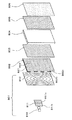
FIG. 3 is an explanatory diagram illustrating the configuration of the variable display device 8. The
[0064]
As for the light emitted from the
[0065]
Note that, without using a light-emitting element and a polarizing filter, it is sufficient to irradiate light of different polarizations from different positions.For example, two light-emitting elements that generate light of different polarizations are provided, and different polarizations are provided. Light may be applied to the
[0066]
The light transmitted through the
[0067]
At this time, the light applied to the liquid
[0068]
Further, of the light applied to the liquid
[0069]
In the liquid
[0070]
A micropole (first polarizing plate) 802 and a polarizing plate 803 (second polarizing plate) are arranged on the
[0071]
The
[0072]
The repetition of the polarization characteristics of the
[0073]
Alternatively, the repetition of the polarization characteristic of the
[0074]
As described above, it is necessary to irradiate the display element (horizontal line) of the liquid
[0075]
That is, the region 802a of the
[0076]
The
[0077]
The
[0078]
Note that the polarization characteristics of the polarizing plate (second polarizing plate) 3 are equal to the polarizing characteristics of the
[0079]
The
[0080]
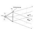
FIG. 4 is a plan view showing an optical system of the variable display device 8.
[0081]
Light emitted from the
[0082]
On the other hand, of the light emitted from the light source, the light that has passed through the
[0083]
In this manner, the light emitted from the
[0084]
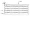
FIG. 5 is an enlarged view of the
[0085]
The
[0086]
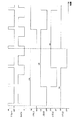
FIG. 6 shows an example of the timing of a signal sent from the
[0087]
Here, in FIG. 6, the duty control signal DTY_CTR is divided into a duty signal LED_A for controlling the
[0088]
In FIG. 6, when the vertical synchronization signal V_SYNC is set to V0, V1, V2, and V3 in order of elapse of time, the
[0089]
At the next rising edge of the vertical synchronization signal V1, the
[0090]
Therefore, the two groups of
[0091]
Further, by synchronizing the blink timing of the
[0092]
Next, an example of light emission control performed by the
[0093]
FIG. 7 is a state transition diagram of the game, FIG. 8 is a flowchart of light emission control performed by the
[0094]
FIG. 7 shows a flowchart of the game, and the outline of the game will be described below with reference to this figure.
[0095]
First, at the beginning of the game (or before the start of the game), the game is in a customer waiting state, and a signal for instructing display of a customer waiting screen is transmitted from the
[0096]
Then, when a game ball hit in the game area of the
[0097]
After a predetermined time elapses after the start of the fluctuation display, the fluctuation display is temporarily stopped in the order of, for example, left, right, and middle (for example, the symbol is slightly fluctuated at the stop position). When a state (for example, a combination in which the left symbol and the right symbol can generate a big hit combination) occurs, a predetermined reach game is performed. In this reach game, for example, the fluctuation display of the middle symbol is performed at an extremely low speed, the fluctuation is changed at a high speed, or the fluctuation display is reversed. In addition, background display and character display are performed according to the reach game.
[0098]
The temporary stop state is a state in which the player can recognize the symbol as a substantially stopped state, and the final stop mode is not determined. The stopped state includes the temporary stop state and the state in which the symbol is stopped. State. In addition, as a specific example of the temporary stop state, in addition to the minute fluctuation at the stop position, there are modes such as enlarging and reducing a symbol, changing the color of the symbol, and changing the shape of the symbol.
[0099]
If the result of the jackpot lottery is a jackpot, the symbols in the left, right, and middle are finally stopped in a predetermined combination of jackpots, and a jackpot game (a special game state advantageous to the player) occurs. When the big hit game occurs, a special game in which the variable winning
[0100]
In this case, if the jackpot is a specific jackpot, a specific game state is generated after the jackpot game, and the probability of occurrence of the next jackpot is increased, or the fluctuation based on the winning of the game ball to the starting
[0101]
When the game ball wins in the starting
[0102]
When a game ball passes through the ordinary
[0103]
FIG. 8 is a flowchart of light emission control performed by the
[0104]
First, in step S1, the control waits for the generation of an interrupt signal accompanying the rise of the vertical synchronization signal (V_SYNC). When the vertical synchronization signal rises, the process proceeds to step S2.
[0105]
In step S2, it is determined whether the display command signal received from the
[0106]
In either case of occurrence of a jackpot or termination of the jackpot, the process proceeds to step S3 to switch the light emission mode.
[0107]
That is, when the signal for notifying the occurrence of the special game state is received, or when the signal for notifying the end of the special game state is generated, the light emission mode is switched.
[0108]
When a big hit occurs, the
[0109]
Here, as shown in the table of FIG. 9, the light emission mode indicates the relationship between the blinking pointer that is sequentially repeated from 0 to 3 every time a vertical synchronization signal is generated and the ON / OFF of the light emission group of the
[0110]
Thereafter, the blinking pointer is incremented by 1 in step S4, and in step S5, the
[0111]
Next, in step S6, the image data is output from the
[0112]
By repeating the above steps S1 to S7, the
[0113]
That is, in the normal
[0114]
On the other hand, the
[0115]
That is, as shown in FIG. 10, at the rising edge of the vertical synchronization signal V0 (blinking pointer = 0), the
[0116]
Next, the
[0117]
Thus, during the variable display game in which the player pays attention to the variable display device 8, the brightness of the
[0118]
Further, the blinking timings of the
[0119]
Further, since the plurality of
[0120]
Further, since the plurality of
[0121]
Further, since the brightness of the variable display device 8 changes according to the game state, the degree of appeal of the information provided by the variable display device 8 to the player can be increased, and the brightness can be changed to an appropriate brightness according to the game state. It is possible to improve interest in the variable display device 8.
[0122]
Further, in the
[0123]
In addition, since a white LED is employed as the
[0124]
Further, the
[0125]
FIG. 11 shows a second embodiment, in which the
[0126]
Each light emitting group is arranged substantially in a line, and is repeatedly arranged in the order of 810A, 810B, 810C, and 810D from the left in the figure. Note that the number of white LEDs in each row may be different, and it is only necessary that the total number of white LEDs be set the same in each light emitting group.
[0127]
These four light emitting groups are driven based on a duty signal from the
[0128]
The ON / OFF switching of the duty signals LED_A to D_D is performed in synchronization with the vertical synchronization signal V_sync, as in the first embodiment. For example, three light emitting groups are always lit, and any one of the light emitting groups Is turned off.
[0129]
That is, in FIG. 12, the duty signal LED_A is turned on at the rise of the vertical synchronization signal V0, and the
[0130]
Next, when the vertical synchronization signal V1 rises, the duty signals LED_A and D maintain the ON state, the duty signal LED_B switches from OFF to ON, the lighting of the
[0131]
In this way, in the large number of
[0132]
As described above, the plurality of light-emitting groups are configured with the same number of white LEDs, and the constant number of white LEDs are constantly turned on, thereby preventing the occurrence of color unevenness and the like on the
[0133]
As shown in FIG. 13, the arrangement of the white LEDs may be such that a plurality of white LEDs are linearly arranged to form a linear light source, and each light emitting group (810A to 810D) may be configured for each line. In this case, it is desirable that the arrangement direction of each group be arranged along the horizontal direction of the
[0134]
Further, when there is a large variation in the brightness of each light emitting group due to a manufacturing error of the white LED or the like, the number of white LEDs constituting each light emitting group may be increased or decreased to make the brightness of each light emitting group uniform.
FIG. 14 shows a third embodiment, in which the
[0135]
Assuming that the horizontal synchronization signal H_SYNC is, for example, 33.3 KHz, ON-OFF is repeated at a cycle of 30 μs, and the
[0136]
Next, the horizontal synchronization signals H1, H2, H, etc. are sequentially generated, and when the number of horizontal synchronization signals reaches a preset value, for example, 32 (clock), the
[0137]
Accordingly, the
[0138]
Further, by synchronizing the blink timing of the
[0139]
The embodiments disclosed this time are to be considered in all respects as illustrative and not restrictive. The scope of the present invention is defined by the terms of the claims, rather than the description above, and is intended to include any modifications within the scope and meaning equivalent to the terms of the claims.
[Brief description of the drawings]
FIG. 1 is a front view showing a configuration of an entire gaming machine according to an embodiment of the present invention.
FIG. 2 is a block diagram showing a part of a control system.
FIG. 3 is an exploded perspective view for explaining the optical system.
FIG. 4 is a plan view of the optical system.
FIG. 5 is a front view of the light source.
FIG. 6 is a timing chart showing a time relationship between drive signals LED_A and LED_B, a vertical synchronization signal V_SYNC, and image information DATA for each group of light emitting elements in a normal state.
FIG. 7 is a state transition diagram of a game.
FIG. 8 is a flowchart illustrating an example of light emission control performed by the display control device.
FIG. 9 is a table showing a flash mode according to a flash mode, a flash group, and a flash pointer.
FIG. 10 is a timing chart illustrating a relationship between drive signals LED_A and LED_B, a vertical synchronization signal V_SYNC, and image information DATA for each group of light emitting elements during a jackpot game.
FIG. 11 is a front view of a light source according to a second embodiment.
FIG. 12 is a timing chart showing a relationship between time and drive signals LED_A, LED_B, LED_C, LED_D, a vertical synchronization signal V_SYNC, and image information DATA for each light emitting element group.
FIG. 13 is a front view of a light source showing another embodiment.
FIG. 14 is a timing chart showing the third embodiment and showing a relationship between time and drive signals LED_A and LED_B, a horizontal synchronization signal H_SYNC for each group of light emitting elements.
[Explanation of symbols]
8 Variable display device
150 Display control device
151 CPU
181 LCD drive
182 Light source drive
801 light source
810 Light-emitting element
810A-D White LED
811 Polarizing filter
812 Fresnel lens
813 Reflector
802 micropole (first polarizing plate)
803 Polarizing plate (second polarizing plate)
804 LCD panel
805 polarizing plate (third polarizing plate)
806 diffuser
Claims (11)
該液晶パネルの表示内容を更新するための信号を生成するタイマ生成手段と、
該タイマ生成手段によって生成された信号に基づき、前記液晶パネルの駆動制御を行って遊技に関わる情報を表示出力させる駆動制御手段と、
を備えた遊技機において、
前記バックライトの光源をそれぞれ制御可能な複数系統で構成するとともに、該複数系統の光源をそれぞれ発光制御するバックライト制御手段を備え、
前記駆動制御手段は、前記タイマ生成手段によって生成された信号に同期して、前記液晶パネルの表示内容を更新する表示内容更新手段を備え、
前記バックライト制御手段は、前記タイマ生成手段によって生成された信号に同期して前記複数系統の光源を系統毎に点滅させる点滅制御手段を備えたことを特徴とする遊技機。A liquid crystal panel illuminated by the backlight,
Timer generation means for generating a signal for updating the display content of the liquid crystal panel;
Drive control means for performing drive control of the liquid crystal panel based on a signal generated by the timer generation means to display and output information relating to a game,
In a gaming machine equipped with
The light source of the backlight is configured with a plurality of controllable light sources, and a backlight control unit that controls light emission of the light sources of the plurality of light sources is provided,
The drive control unit includes a display content update unit that updates display content of the liquid crystal panel in synchronization with a signal generated by the timer generation unit,
A gaming machine, wherein the backlight control means includes blinking control means for blinking the plurality of light sources for each system in synchronization with a signal generated by the timer generating means.
前記タイマ生成手段は、前記図柄の変動速度に対応して前記信号を発生させることを特徴とする請求項1ないし請求項6の何れか一つに記載の遊技機。A gaming machine capable of performing a variable display of symbols on the liquid crystal panel and generating a special gaming state in relation to a display mode of the symbols,
The gaming machine according to any one of claims 1 to 6, wherein the timer generating means generates the signal in accordance with a speed at which the symbol fluctuates.
Priority Applications (1)
| Application Number | Priority Date | Filing Date | Title |
|---|---|---|---|
| JP2002246497A JP2004081504A (en) | 2002-08-27 | 2002-08-27 | Game machine |
Applications Claiming Priority (1)
| Application Number | Priority Date | Filing Date | Title |
|---|---|---|---|
| JP2002246497A JP2004081504A (en) | 2002-08-27 | 2002-08-27 | Game machine |
Publications (2)
| Publication Number | Publication Date |
|---|---|
| JP2004081504A true JP2004081504A (en) | 2004-03-18 |
| JP2004081504A5 JP2004081504A5 (en) | 2005-09-02 |
Family
ID=32054384
Family Applications (1)
| Application Number | Title | Priority Date | Filing Date |
|---|---|---|---|
| JP2002246497A Pending JP2004081504A (en) | 2002-08-27 | 2002-08-27 | Game machine |
Country Status (1)
| Country | Link |
|---|---|
| JP (1) | JP2004081504A (en) |
Cited By (8)
| Publication number | Priority date | Publication date | Assignee | Title |
|---|---|---|---|---|
| JP2008136634A (en) * | 2006-12-01 | 2008-06-19 | Daiichi Shokai Co Ltd | Game machine |
| JP2011024801A (en) * | 2009-07-27 | 2011-02-10 | Maruhon Industry Co Ltd | Pachinko game machine |
| JP2013039448A (en) * | 2012-11-27 | 2013-02-28 | Maruhon Industry Co Ltd | Pachinko game machine |
| JP2015077460A (en) * | 2014-12-26 | 2015-04-23 | 株式会社ソフイア | Game machine |
| JP2015091367A (en) * | 2014-12-26 | 2015-05-14 | 株式会社ソフイア | Game machine |
| JP2015213586A (en) * | 2014-05-09 | 2015-12-03 | 株式会社サンセイアールアンドディ | Game machine |
| JP2016049273A (en) * | 2014-08-29 | 2016-04-11 | 株式会社三共 | Game machine |
| JP2018153486A (en) * | 2017-03-17 | 2018-10-04 | 株式会社三共 | Game machine |
-
2002
- 2002-08-27 JP JP2002246497A patent/JP2004081504A/en active Pending
Cited By (8)
| Publication number | Priority date | Publication date | Assignee | Title |
|---|---|---|---|---|
| JP2008136634A (en) * | 2006-12-01 | 2008-06-19 | Daiichi Shokai Co Ltd | Game machine |
| JP2011024801A (en) * | 2009-07-27 | 2011-02-10 | Maruhon Industry Co Ltd | Pachinko game machine |
| JP2013039448A (en) * | 2012-11-27 | 2013-02-28 | Maruhon Industry Co Ltd | Pachinko game machine |
| JP2015213586A (en) * | 2014-05-09 | 2015-12-03 | 株式会社サンセイアールアンドディ | Game machine |
| JP2016049273A (en) * | 2014-08-29 | 2016-04-11 | 株式会社三共 | Game machine |
| JP2015077460A (en) * | 2014-12-26 | 2015-04-23 | 株式会社ソフイア | Game machine |
| JP2015091367A (en) * | 2014-12-26 | 2015-05-14 | 株式会社ソフイア | Game machine |
| JP2018153486A (en) * | 2017-03-17 | 2018-10-04 | 株式会社三共 | Game machine |
Similar Documents
| Publication | Publication Date | Title |
|---|---|---|
| JP3967667B2 (en) | Game machine | |
| JP2004287057A (en) | Game machine | |
| JP4572184B2 (en) | Game machine | |
| JP2004081504A (en) | Game machine | |
| JP3994050B2 (en) | Game machine | |
| JP4060865B2 (en) | Game machine | |
| JP3705792B2 (en) | Image display device | |
| JP3960909B2 (en) | Game machine | |
| JP3795025B2 (en) | Game machine | |
| JP4068998B2 (en) | Game machine | |
| JP2004159889A (en) | Game machine | |
| JP2004166886A (en) | Game machine | |
| JP2004283222A (en) | Game machine | |
| JP2004254820A (en) | Game machine | |
| JP3782998B2 (en) | Image display device | |
| JP3698702B2 (en) | Image display device | |
| JP4457128B2 (en) | Game machine | |
| JP2004283312A (en) | Game machine | |
| JP2004283219A (en) | Game machine | |
| JP4252820B2 (en) | Game machine | |
| JP3923417B2 (en) | Game machine | |
| JP4154263B2 (en) | Image display device and game machine equipped with image display device | |
| JP3792206B2 (en) | Game machine | |
| JP4080858B2 (en) | Game machine | |
| JP2004229881A (en) | Image display device and game machine with the same |
Legal Events
| Date | Code | Title | Description |
|---|---|---|---|
| A521 | Written amendment |
Free format text: JAPANESE INTERMEDIATE CODE: A523 Effective date: 20050223 |
|
| A621 | Written request for application examination |
Free format text: JAPANESE INTERMEDIATE CODE: A621 Effective date: 20050223 |
|
| A977 | Report on retrieval |
Free format text: JAPANESE INTERMEDIATE CODE: A971007 Effective date: 20080611 |
|
| A131 | Notification of reasons for refusal |
Free format text: JAPANESE INTERMEDIATE CODE: A131 Effective date: 20080617 |
|
| A521 | Written amendment |
Free format text: JAPANESE INTERMEDIATE CODE: A523 Effective date: 20080807 |
|
| A02 | Decision of refusal |
Free format text: JAPANESE INTERMEDIATE CODE: A02 Effective date: 20090217 |